

hilscher COMX 10CA-DPS, COMX 10CA-DNS, COMX 10CN-DNS, COMX 50CA-REFO, COMX 50CA-CCS Design Manual
...Page 1
Design Guide
COMX Communication Modules
Hilscher Gesellschaft für Systemautomation mbH
www.hilscher.com
DOC100901DG18EN | Revision 18 | English | 2013-12 | Released | Public
Page 2

Introduction 2/78
Table of Contents
1 Introduction.............................................................................................................................................4
1.1 About this Document......................................................................................................................4
1.2 Comparison COMX and COM Modules.........................................................................................5
1.3 List of Revisions .............................................................................................................................6
1.4 Technical Features.........................................................................................................................7
1.5 Module Names ...............................................................................................................................9
1.6 References to Documents............................................................................................................10
1.7 Legal Notes ..................................................................................................................................11
1.7.1 Copyright ......................................................................................................................................... 11
1.7.2 Important Notes............................................................................................................................... 11
1.7.3 Exclusion of Liability ........................................................................................................................ 12
1.7.4 Warranty.......................................................................................................................................... 12
1.7.5 Export Regulations .......................................................................................................................... 12
2 Design-In - Mechanical Aspects .........................................................................................................13
2.1 Type of COMX Modules...............................................................................................................13
2.2 Mechanical Dimensions ...............................................................................................................15
2.2.1 Common Mechanical Dimensions for COMX Modules.................................................................... 15
2.2.2 Mechanical Dimensions of COMX Modules .................................................................................... 15
2.3 Type of Connector........................................................................................................................25
2.3.1 Storage and Contact Reliability of Host-side Connector.................................................................. 27
2.4 Mounting of COMX Modules........................................................................................................28
2.5 Material Recommendation for the Faceplate ...............................................................................34
2.6 Designation of the COMX Module ...............................................................................................34
2.7 Meaning of the Address Switch ...................................................................................................34
2.7.1 PROFIBUS DP Slave ...................................................................................................................... 34
2.7.2 CANopen Slave............................................................................................................................... 35
2.7.3 DeviceNet Slave.............................................................................................................................. 35
2.7.4 CC-Link Slave ................................................................................................................................. 36
2.7.4.1 COMX 10CA-CCS and COMX 10CN-CCS....................................................................... 36
2.7.4.2 COMX 50CA-CCS ............................................................................................................ 37
3 Design-In - Electrical Aspects.............................................................................................................39
3.1 Host Interface...............................................................................................................................39
3.1.1 Host Interface Overview: Dual-Port Memory Sizes and Modes....................................................... 39
3.1.2 Host Interface: Parallel or serial Dual-Port Memory Mode............................................................... 40
3.1.2.1 COMX 50 and COMX 100 ................................................................................................ 40
3.1.2.2 COMX 10 and COMX 51 .................................................................................................. 40
3.1.3 COMX Pinning of the System Bus Connector X1 – Parallel Mode.................................................. 41
3.1.4 COMX Pinning of the System Bus Connector X1 – Serial Mode..................................................... 43
3.1.5 PAD Type Explanation .................................................................................................................... 44
3.1.6 Signal Overview and Pinning of the Fieldbus Connector X2 on COMX CN..................................... 46
3.1.6.1 Fieldbus Connector X2 for CC-Link Slave ........................................................................ 46
3.1.6.2 Fieldbus Connector X2 for CANopen-Master/-Slave ........................................................ 47
3.1.6.3 Fieldbus Connector X2 for DeviceNet-Master/-Slave ....................................................... 48
3.1.6.4 Fieldbus Connector X2 for PROFIBUS-Master/-Slave...................................................... 49
3.1.6.5 Fieldbus Connector X2 for Real Time Ethernet ................................................................ 50
3.1.7 Common Signals of the Host Interface............................................................................................ 52
3.1.7.1 Power Supply of the COMX Modules ............................................................................... 52
3.1.7.2 RESET Signal................................................................................................................... 52
3.1.8 Signals of the Host Interface – Parallel Dual-Port Memory Mode.................................................... 52
3.1.8.1 The Dual-Port Memory Bus of COMX............................................................................... 52
3.1.8.2 Address Bus and Data Bus............................................................................................... 53
3.1.8.3 Dual-Port Memory Control Lines....................................................................................... 53
3.1.8.4 Interrupt Line to the Host System ..................................................................................... 53
3.1.8.5 BUSY Line to the Host System ......................................................................................... 54
3.1.8.6 Interfacing to the Dual-Port Memory for COMX ................................................................ 54
3.1.8.7 Timing Diagram parallel Dual-Port Memory Interface ....................................................... 55
3.1.8.8 Integration of COMX Module into a Host System ............................................................. 57
3.1.9 Signals of the Host Interface – Serial Dual-Port Memory Mode ...................................................... 58
3.2 Fieldbus Interface.........................................................................................................................59
3.3 LEDs.............................................................................................................................................60
3.4 Diagnostic Interface .....................................................................................................................62
3.4.1 Diagnostic Interface RS232C .......................................................................................................... 62
COMX Communication Modules | Design Guide
DOC100901DG18EN | Revision 18 | English | 2013-12 | Released | Public © Hilscher, 2002-2013
Page 3

Introduction 3/78
3.4.2
Diagnostic Interface USB ................................................................................................................ 63
3.5 SYNC Signals ..............................................................................................................................66
4 Technical Data ......................................................................................................................................67
4.1 Product Tests ...............................................................................................................................68
4.1.1 COMX 10CA-CCS........................................................................................................................... 68
4.1.2 COMX 10CN-CCS........................................................................................................................... 68
4.1.3 COMX 10CA-COS........................................................................................................................... 68
4.1.4 COMX 10CN-COS .......................................................................................................................... 69
4.1.5 COMX 10CA-DPS ........................................................................................................................... 69
4.1.6 COMX 10CN-DPS........................................................................................................................... 69
4.1.7 COMX 10CA-DNS........................................................................................................................... 70
4.1.8 COMX 10CN-DNS........................................................................................................................... 70
4.1.9 COMX 50CA-REFO ........................................................................................................................ 70
4.1.10 COMX 50CA-CCS ........................................................................................................................... 71
4.1.11 COMX 51CA-RE ............................................................................................................................. 71
4.1.12 COMX 100CA-CO ........................................................................................................................... 71
4.1.13 COMX 100CA-DN ........................................................................................................................... 72
4.1.14 COMX 100CA-DP ........................................................................................................................... 72
4.1.15 COMX 100CA-RE ........................................................................................................................... 72
4.1.16 COMX 100CN-CO ........................................................................................................................... 73
4.1.17 COMX 100CN-DN ........................................................................................................................... 73
4.1.18 COMX 100CN-DP ........................................................................................................................... 74
4.1.19 COMX 100CN-RE ........................................................................................................................... 74
5 Appendix ...............................................................................................................................................75
5.1 List of Tables................................................................................................................................75
5.2 List of Figures...............................................................................................................................77
5.3 Contacts .......................................................................................................................................78
COMX Communication Modules | Design Guide
DOC100901DG18EN | Revision 18 | English | 2013-12 | Released | Public © Hilscher, 2002-2013
Page 4

Introduction 4/78
1 Introduction
1.1 About this Document
COMX means Communication Modules netX. These modules provide a universal and easy to use
fieldbus interface for integration on various host systems. Through the set of standard application
interfaces and the same board dimensions in each COMX family it is easy to switch between the
different fieldbus systems, e.g. PROFIBUS DP, CANopen, DeviceNet, CC-Link or Ethernet by
changing the module.
This manual describes only the hardware part of the modules.
The COMX communication modules is a generation of Modules and offer beside fieldbus communication also Real-Time Ethernet communication. The application interface is different (not compatible) compared to COM Modules. The application interface of the COMX Modules is common to
all our COMX communication modules, and PC cards CIFX and netJACK communication modules
described in our toolkit manual, dual-port memory interface manual and the Real Time Ethernet
respectively fieldbus related details are defined in our Protocol API Manuals.
COM Modules are the previous generation of communication modules. The COM Modules are described in an own manual. The following two tables give a comparison of both COM and COMX
Modules.
COMX Communication Modules | Design Guide
DOC100901DG18EN | Revision 18 | English | 2013-12 | Released | Public © Hilscher, 2002-2013
Page 5
Introduction 5/78
1.2 Comparison COMX and COM Modules
Basic differences between COM and COMX
COM COMX
Processor EC1 netX
Host Interface 8 Bit 8 / 16 Bit
Dual-Port Memory size 2 KByte or 8 KByte 8 KByte or 16 KByte
See section Host Interface Overview: Dual-Port
Memory Si
USB Interface No Yes
Table 1: Basic differences between COM and COMX
Comparison of supported protocols for COM and COMX
COM COMX (in this manual)
AS-Interface Master supported CANopen Master supported supported
CANopen Slave supported supported
CC-Link Slave supported supported
DeviceNet Master supported supported
DeviceNet Slave supported supported
InterBus Slave supported not supported by netX technology
PROFIBUS DP Master supported supported
PROFIBUS DP Slave supported supported
PROFIBUS MPI supported supported
sercos II (second generation) supported not supported by netX technology
EtherCAT Master - supported
EtherCAT Slave - supported
EtherNet/IP Scanner (Master) - supported
EtherNet/IP Adapter (Slave) supported supported
Open Modbus/TCP supported supported
POWERLINK Controlled Node - supported
PROFINET IO RT Controller - supported
PROFINET IO RT Device - supported
sercos Master (third generation) - supported
sercos Slave (third generation) - supported
VARAN Client (Slave) - supported
Table 2: Comparison of supported protocols for COM and COMX
zes and Modes on page 39.
COMX Communication Modules | Design Guide
DOC100901DG18EN | Revision 18 | English | 2013-12 | Released | Public © Hilscher, 2002-2013
Page 6

Introduction 6/78
1.3 List of Revisions
Rev Date Name Chapter Revision
13 2011-09-30 HH
14 2011-10-05 HH
15 2012-03-22
New Protocols: VARAN Client (Slave), PROFIBUS MPI
2.2.2
2.7
3.1.2 Section Host Interface: Parallel or serial Dual-Port Memory Mode added
3.1.3
3.1.4
3.1.6.1 Section Fieldbus Connector X2 for CC-Link Slave added
3.1.8.7
3.1.9
3.2 Section Fieldbus Interface added
4.1 Section Dual-Port Memory Size added
4.1 Section Product Tests COMX 10xx-xxx and COMX 50CA-REFO added
16 2012-07-11 RG 4
17 2013-07-17 RG
18 2013-12-02 RG/HH COMX 51CA-RE added.
3.1.1
3.1.6.5 Typo corrected to J8064D628ANL.
3.1.8.5 Added information that the important note not is valid for COMX10/COMX51
3.1.8.7 Table 37: Symbols for COMX Timing Diagram for Read and Write Access:
3.5 Update of section “SYNC Signals”
4.1.11 Added new EMV data section for COMX 51CA-RE
Table 3: List of Revisions
HH
MP
2.2.2
2.5
4
4.1.15
Section Mechanical Dimensions of COMX Modules: up
(Correction dimension from 5,08 to 2,54), updated to M1100052
Section Meaning of the Address Switch add
Meaning of LEDs moved to ‘comX User Manual’.
Section Timing Diagram parallel Dual-Port M
gram updated, Timing values for COMX 100, COMX 50 and common values
added (Table 37).
COMX 10CA-DPS, COMX 10CN-DPS, COMX 10CA-DNS,
COMX 10CN-DNS, COMX 10CA-COS, COMX 10CN-COS,
COMX 10CA-CCS, COMX 10CN-CCS, COMX 50CA-REFO
communication modules added
Section Mechanical Dimensions of COMX Modules: up
M1100121 added, M1100131 added, updated to M0900164, updated to
M0600174
Section Meaning of the Address Switch: Sections PROFIBUS DP Slave,
CANopen Slave, DeviceNet Slave a
10CN-CCS added
New: Serial dual-port memory mode (for COMX 10)
Section COMX Pinning of the System Bus Connector X1 – Parallel Mode:
- COMX
- Symbol names for signals with new convention used (DPM_...).
- Information about PAD type added
Section COMX Pinning of the System Bus Connector X1 – Serial Mode for
COMX 10
Section Timing Diagram parallel Dual-Port Memory Interface: COMX
values added (Table 37).
Section Signals of the Host Interface – Serial Dual-Port Memory Mode
add
Current consumption values of COMX 10xx-xxx and COMX 50CA-REFO
updated
Section Mechanical Dimensions of COMX Modules: up
M0600175.
New section Material Recommendation for the Faceplate a
Operating conditions for COMX 100CA-RE for revision 8 updated.
EMC data COMX 100CA-RE for revision 8 updated.
Section Dual-Port Memory Size moved and expanded to Host Interface
Overview
Added column for COMX 51,
updated some values for COMX 10 (t
10
added
ed
: Dual-Port Memory Sizes and Modes.
nd COMX 10CA-CCS and COMX
ed
emory Interface: Timing Dia-
to t5 ) and in column “Common”
3
dated to M1100042
dated to M0300636,
10
date of M0600174 to
dded.
COMX Communication Modules | Design Guide
DOC100901DG18EN | Revision 18 | English | 2013-12 | Released | Public © Hilscher, 2002-2013
Page 7

Introduction 7/78
1.4 Technical Features
Common Technical Features for COMX
All leading Fieldbus and Real Time Ethernet Protocols available as Master and Slave
One common hardware for all Real Time Ethernet Protocols
Easy to use dual-port memory interface, with additional serial and diagnostic interface
USB or serial diagnostic interface at COMX
Host interface is designed for 8 KBytes (COMX 10) and for 16 KByte (COMX 50 and COMX
100) address space of the dual-port memory with selectable bus width of 8 or 16 bit.
3.3 V power supply reduces power consumption
Small footprint for the host connector with 50 mil grid
Solid mechanical assembly and a massive connection to earth ground by metal blocks spe-
cial design for the requirements of the modules with fieldbus connector
Two dowels for exact mounting of the module on the host board
Metal blocks can easily modified for special customer requirements
Front panel can be mounted on the metal blocks that the modules have always the same
front size and covers the fieldbus connector
Many modules are available in extended temperature specification (operating temperature
range -20°C … +65°C)
COMX 10 modules have address switches to set the bus address
COMX 10 and COMX 51 modules offer a serial dual-port memory mode as interface to the
host
CA and CN Types of COMX Modules
For the COMX family, Hilscher offers modules with angled and without fieldbus connectors:
COMX 10CN and COMX 100CN
COMX Modules without fieldbus respectively Ethernet connector
COMX 10CA, COMX 50CA, COMX 51CA and COMX 100CA
COMX Modules with angled fieldbus, Ethernet respectively fiber optics connector
COMX Communication Modules | Design Guide
DOC100901DG18EN | Revision 18 | English | 2013-12 | Released | Public © Hilscher, 2002-2013
Page 8
Introduction 8/78
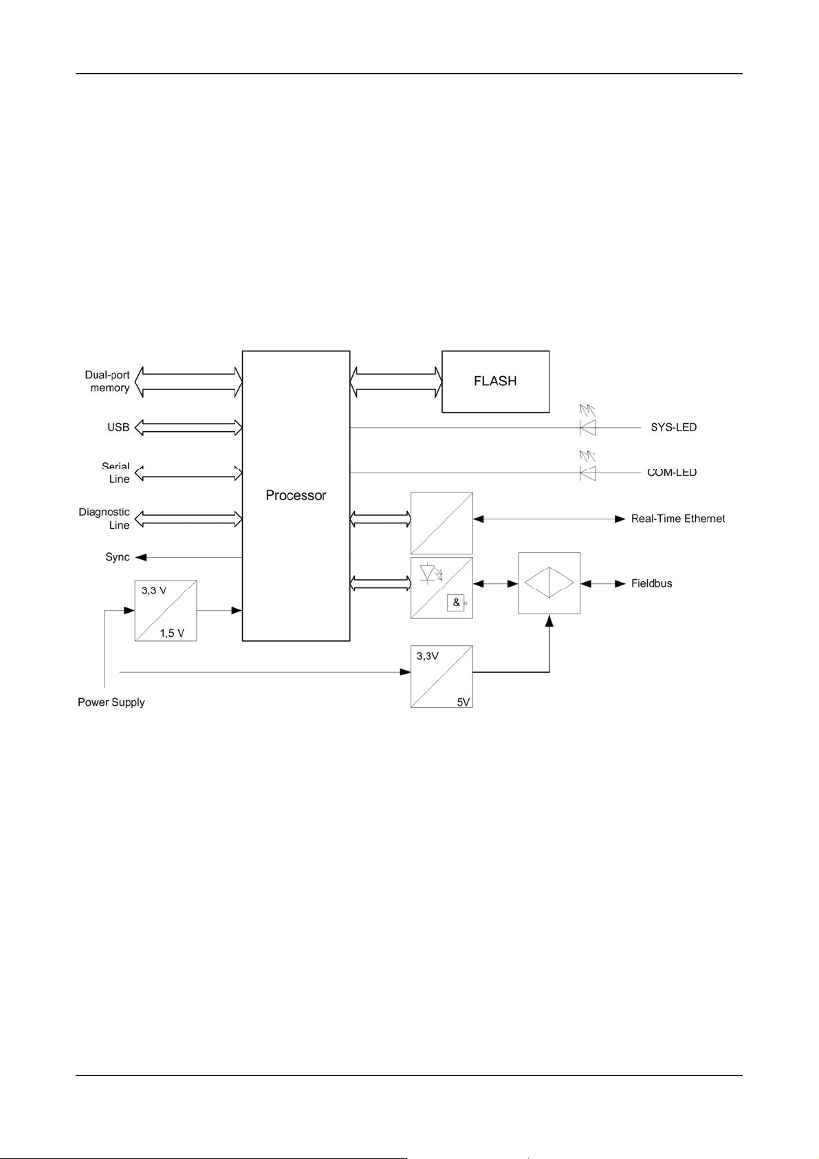
Description of COMX Modules
All COMX have a powerful processor and a complete fieldbus respectively Real-Time Ethernet interface including isolated drivers and the connector according to the standard.
All boards require only a single stabilized 3.3 Voltage. All other voltages are created by DC/DC
converter on the COMX Module.
The access to the COMX Module is through the dual-port memory which can be easily integrated
as a static memory device. It has a non multiplexed 8 or 16 bit data bus with several control lines to
the host system. Between the COMX Module and the host system it is possible to generate interrupts for data handling.
Generally the firmware and the configuration data are stored permanently in FLASH memory by
loading the data through the dual-port memory.
Figure 1: Block Diagram of the COMX Modules
COMX Communication Modules | Design Guide
DOC100901DG18EN | Revision 18 | English | 2013-12 | Released | Public © Hilscher, 2002-2013
Page 9

Introduction 9/78
1.5 Module Names
The following table lists all COMX modules. The range of products will be expanded with COMX
modules with netX 10 or with netX 51. As a result of this expansion, it was necessary to rename
the existing COMX modules by adding ‘100’ to the name, which indicates that netX 100 is used on
the module respectively by adding ‘50’ to the name, which indicates that netX 50 is used etc.
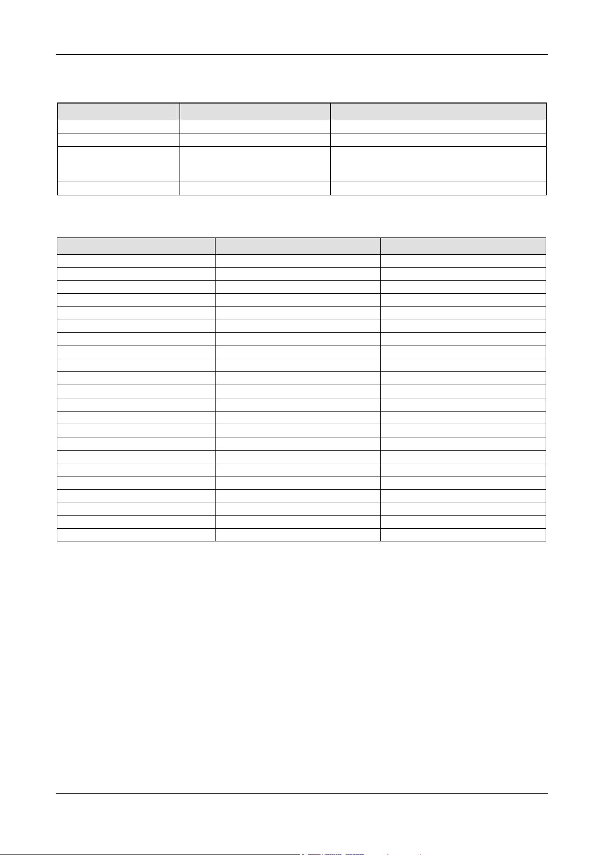
Communication System Old Module Name New Module Name
Real-Time Ethernet
CANopen Slave
CC-Link Slave
DeviceNet Slave
PROFIBUS DP Slave
Table 4: comX Modules – Old and new Names
COMX-CA-RE COMX 100CA-RE
COMX-CN-RE COMX 100CN-RE
- COMX 50CA-REFO
- COMX 51CA-RE
COMX-CA-COM COMX 100CA-CO CANopen Master
COMX-CN-COM COMX 100CN-CO
COMX-CA-COS COMX 100CA-CO
COMX-CN-COS COMX 100CN-CO
- COMX 10CA-COS
- COMX 10CN-COS
COMX-CA-CCS COMX 50CA-CCS
- COMX 10CA-CCS
- COMX 10CN-CCS
COMX-CA-DNM COMX 100CA-DN DeviceNet Master
COMX-CN-DNM COMX 100CN-DN
COMX-CA-DNS COMX 100CA-DN
COMX-CN-DNS COMX 100CN-DN
- COMX 10CA-DNS
- COMX 10CN-DNS
COMX-CA-DPM COMX 100CA-DP PROFIBUS DP Master
COMX-CN-DPM COMX 100CN-DP
COMX-CA-DPS COMX 100CA-DP
COMX-CN-DPS COMX 100CN-DP
- COMX 10CA-DPS
- COMX 10CN-DPS
COMX Communication Modules | Design Guide
DOC100901DG18EN | Revision 18 | English | 2013-12 | Released | Public © Hilscher, 2002-2013
Page 10

Introduction 10/78
1.6 References to Documents
This document refers to the following documents:
[1] Hilscher Gesellschaft für Systemautomation mbH: Dual-Port Memory Interface Manual, netX
based products, Revision 12, English, 2012
[2] Hilscher Gesellschaft für Systemautomation mbH: User Manual, comX, Communication
Modules for Real-Time Ethernet and Fieldbus, Revision 4, English, 2013
[3] Hilscher Gesellschaft für Systemautomation mbH: Benutzerhandbuch, comX, Kommunica-
tionsmodule für Real-Time Ethernet und Feldbus, Revision 4, German, 2013
[4] Hilscher Gesellschaft für Systemautomation mbH: Getting Started Guide, Serial Dual-Port
Memory Interface with netX, Revision 1, English, 2012
[5] Hilscher Gesellschaft für Systemautomation mbH: Technical Data Reference Guide, netX 10,
Revision 0.9, English, 2011-12
[6] Hilscher Gesellschaft für Systemautomation mbH: Technical Data Reference Guide, netX
51/52, Revision 2, English, 2012-13
[7] Hilscher Gesellschaft für Systemautomation mbH: EtherCAT V4 Protocol API, Revision 3,
English, 2011-2013 (Doc-ID DOC110909API03EN)
[8] Hilscher Gesellschaft für Systemautomation mbH: sercos V3 Protocol API, Revision 11,
English, 2008-2013 (Doc-ID DOC100205API11EN)
Table 5: References to Documents
COMX Communication Modules | Design Guide
DOC100901DG18EN | Revision 18 | English | 2013-12 | Released | Public © Hilscher, 2002-2013
Page 11

Introduction 11/78
1.7 Legal Notes
1.7.1 Copyright
© Hilscher, 2002-2013, Hilscher Gesellschaft für Systemautomation mbH
All rights reserved.
The images, photographs and texts in the accompanying material (user manual, accompanying
texts, documentation, etc.) are protected by German and international copyright law as well as international trade and protection provisions. You are not authorized to duplicate these in whole or in
part using technical or mechanical methods (printing, photocopying or other methods), to manipulate or transfer using electronic systems without prior written consent. You are not permitted to
make changes to copyright notices, markings, trademarks or ownership declarations. The included
diagrams do not take the patent situation into account. The company names and product descriptions included in this document may be trademarks or brands of the respective owners and may be
trademarked or patented. Any form of further use requires the explicit consent of the respective
rights owner.
1.7.2 Important Notes
The user manual, accompanying texts and the documentation were created for the use of the
products by qualified experts, however, errors cannot be ruled out. For this reason, no guarantee
can be made and neither juristic responsibility for erroneous information nor any liability can be assumed. Descriptions, accompanying texts and documentation included in the user manual do not
present a guarantee nor any information about proper use as stipulated in the contract or a warranted feature. It cannot be ruled out that the user manual, the accompanying texts and the documentation do not correspond exactly to the described features, standards or other data of the delivered product. No warranty or guarantee regarding the correctness or accuracy of the information
is assumed.
We reserve the right to change our products and their specification as well as related user manuals, accompanying texts and documentation at all times and without advance notice, without obligation to report the change. Changes will be included in future manuals and do not constitute any
obligations. There is no entitlement to revisions of delivered documents. The manual delivered with
the product applies.
Hilscher Gesellschaft für Systemautomation mbH is not liable under any circumstances for direct,
indirect, incidental or follow-on damage or loss of earnings resulting from the use of the information
contained in this publication.
COMX Communication Modules | Design Guide
DOC100901DG18EN | Revision 18 | English | 2013-12 | Released | Public © Hilscher, 2002-2013
Page 12

Introduction 12/78
1.7.3 Exclusion of Liability
The software was produced and tested with utmost care by Hilscher Gesellschaft für Systemautomation mbH and is made available as is. No warranty can be assumed for the performance and
flawlessness of the software for all usage conditions and cases and for the results produced when
utilized by the user. Liability for any damages that may result from the use of the hardware or software or related documents, is limited to cases of intent or grossly negligent violation of significant
contractual obligations. Indemnity claims for the violation of significant contractual obligations are
limited to damages that are foreseeable and typical for this type of contract.
It is strictly prohibited to use the software in the following areas:
for military purposes or in weapon systems;
for the design, construction, maintenance or operation of nuclear facilities;
in air traffic control systems, air traffic or air traffic communication systems;
in life support systems;
in systems in which failures in the software could lead to personal injury or injuries leading to
death.
We inform you that the software was not developed for use in dangerous environments requiring
fail-proof control mechanisms. Use of the software in such an environment occurs at your own risk.
No liability is assumed for damages or losses due to unauthorized use.
1.7.4 Warranty
Although the hardware and software was developed with utmost care and tested intensively, Hilscher Gesellschaft für Systemautomation mbH does not guarantee its suitability for any purpose
not confirmed in writing. It cannot be guaranteed that the hardware and software will meet your requirements, that the use of the software operates without interruption and that the software is free
of errors. No guarantee is made regarding infringements, violations of patents, rights of ownership
or the freedom from interference by third parties. No additional guarantees or assurances are
made regarding marketability, freedom of defect of title, integration or usability for certain purposes
unless they are required in accordance with the law and cannot be limited. Warranty claims are
limited to the right to claim rectification.
1.7.5 Export Regulations
The delivered product (including the technical data) is subject to export or import laws as well as
the associated regulations of different counters, in particular those of Germany and the USA. The
software may not be exported to countries where this is prohibited by the United States Export
Administration Act and its additional provisions. You are obligated to comply with the regulations at
your personal responsibility. We wish to inform you that you may require permission from state authorities to export, re-export or import the product.
COMX Communication Modules | Design Guide
DOC100901DG18EN | Revision 18 | English | 2013-12 | Released | Public © Hilscher, 2002-2013
Page 13

Design-In - Mechanical Aspects 13/78
2 Design-In - Mechanical Aspects
2.1 Type of COMX Modules
The following table gives an overview on the availability of the different COMX Modules.
Module Fieldbus / Protocol Type Connector
COMX 10
COMX 10CA-COS CANopen Slave angled
COMX 10CN-COS CANopen Slave no
COMX 10CA-CCS CC-Link Slave angled
COMX 10CN-CCS CC-Link Slave no
COMX 10CA-DPS PROFIBUS DP Slave angled
COMX 10CN-DPS PROFIBUS DP Slave no
COMX 10CA-DNS DeviceNet Slave angled
COMX 10CN-DNS DeviceNet Slave no
COMX 50
COMX 50CA-CCS CC-Link Slave angled
COMX 50CA-REFO PROFINET IO Device angled
COMX 51
COMX 51CA-RE Realtime Ethernet Slave angled
COMX 100
COMX 100CA-CO CANopen
COMX 100CN-CO CANopen
COMX 100CA-DN DeviceNet
COMX 100CN-DN DeviceNet
COMX 100CA-DP PROFIBUS DP
COMX 100CN-DP PROFIBUS DP
COMX 100CA-RE Realtime Ethernet
COMX 100CN-RE Realtime Ethernet
Table 6: Available comX Modules
Master or Slave
(depends on loaded firmware)
Master or Slave
(depends on loaded firmware)
Master or Slave
(depends on loaded firmware)
Master or Slave
(depends on loaded firmware)
Master or Slave
(depends on loaded firmware)
Master or Slave
(depends on loaded firmware)
Master or Slave
(depends on loaded firmware)
Master or Slave
(depends on loaded firmware)
angled
no
angled
no
angled
no
angled
no
COMX Communication Modules | Design Guide
DOC100901DG18EN | Revision 18 | English | 2013-12 | Released | Public © Hilscher, 2002-2013
Page 14

Design-In - Mechanical Aspects 14/78
The following figures show the position of connector X1 and X2.
CA Types
Figure 2: COMX CA Type - Connector X1
CN Types
Figure 3: COMX CN Type - Connectors X1 and X2
COMX Communication Modules | Design Guide
DOC100901DG18EN | Revision 18 | English | 2013-12 | Released | Public © Hilscher, 2002-2013
Page 15

Design-In - Mechanical Aspects 15/78
2.2 Mechanical Dimensions
2.2.1 Common Mechanical Dimensions for COMX Modules
After mounting the COMX-CA Module parallel at a basis board the rotary switches, LEDs and the
fieldbus connector are on the top side and are angled to the basis board. The edge of all front elements are in one layer which is 2.5 mm ahead of the edge of printed circuit board of the COMX
Module.
The COMX-CN Module has to be used if the mechanical dimensions or order of the LEDs,
switches and fieldbus connector does not fit. In that case you have to place these components directly on the motherboard and feed the signals to the connector X2 of the COMX-CN Module.
Note Please take care on the isolation distance, because the optical isolation interface is on
the module!
Especially for 12 MBit PROFIBUS the distance should be as small as possible.
For Ethernet the signal traces should run parallel and should have the same length.
Please refer at the fieldbus standards for further information!
2.2.2 Mechanical Dimensions of COMX Modules
The COMX Module has a board size of 30 x 70 mm.
The maximum height of the components at the top side of the printed circuit board is 14.0 mm including the fieldbus connector which is also the component defining the height of the CA type. For
the CN type, the parts defining the height of these modules are the DC/DC converter and the transformer.
In order to assure the long-term availability of the modules, Hilscher claims the right to perform a
redesign if necessary due to changes in availability of components and to exchange these components by similar ones which might differ in their dimensions.
In detail, the current minimum space requirements are given by the following table right below.
COMX Module Minimum required space on top of top side of the printed circuit board
CA type 14 mm
CN type 9 mm
Table 7: Minimum Required Space on top of Top Side of the Printed Circuit Board
However, in order
to be able to exchange a COMX module against any other type of COMX module later
and to be sure that future COMX modules which might have been affected by a redesign will
fit under any circumstances
and to avoid thermal problems,
we urgently recommend to obey the following rule:
Note: Keep the space of 14.0 mm above the top side of the COMX modules free.
At the bottom side the maximum height is 4.0 mm, therefore you have 2.5 mm space for components on the host board below the module. The power dissipation in that area should be less than
330 mW!
COMX Communication Modules | Design Guide
DOC100901DG18EN | Revision 18 | English | 2013-12 | Released | Public © Hilscher, 2002-2013
Page 16

Design-In - Mechanical Aspects 16/78
For further module development please reserve additional 10 mm space behind the module. There
are a few larger fieldbus interfaces which does not fit on the small board space. In that case a second printed circuit board will be mounted on top of the module and the 10 mm space is necessary
for the connection with flex stripe between these boards.
The general dimensions of the COMX Modules are shown on the following drawings:
M0200376 General Mechanical dimension of COMX-CA-XXX
M0200466 Mechanical dimension of COMX-CN-XXX
M0300636 Mechanical dimension of light pipe of COMX 10/50/51/100CA-XXX
M1100042 Mechanical dimension of light pipe of COMX 50CA-CCS
M0600175 Mechanical dimension of cover and connector of COMX 100CA-RE
M1100121 Mechanical dimension of cover and connector of COMX 50CA-REFO
M1100131 Mechanical dimension of cover and connector of COMX 10CA-XXX (fieldbus)
M0900164 Mechanical dimension of cover and connector of COMX 100CA-XXX (fieldbus)
M1100052 Mechanical dimension of cover and rotary switch of COMX 50-CA-CCS
COMX Communication Modules | Design Guide
DOC100901DG18EN | Revision 18 | English | 2013-12 | Released | Public © Hilscher, 2002-2013
Page 17

Design-In - Mechanical Aspects 17/78
COMX Communication Modules | Design Guide
DOC100901DG18EN | Revision 18 | English | 2013-12 | Released | Public © Hilscher, 2002-2013
Page 18

Design-In - Mechanical Aspects 18/78
COMX Communication Modules | Design Guide
DOC100901DG18EN | Revision 18 | English | 2013-12 | Released | Public © Hilscher, 2002-2013
Page 19

Design-In - Mechanical Aspects 19/78
COMX Communication Modules | Design Guide
DOC100901DG18EN | Revision 18 | English | 2013-12 | Released | Public © Hilscher, 2002-2013
Page 20

Design-In - Mechanical Aspects 20/78
COMX Communication Modules | Design Guide
DOC100901DG18EN | Revision 18 | English | 2013-12 | Released | Public © Hilscher, 2002-2013
Page 21

Design-In - Mechanical Aspects 21/78
COMX Communication Modules | Design Guide
DOC100901DG18EN | Revision 18 | English | 2013-12 | Released | Public © Hilscher, 2002-2013
Page 22

Design-In - Mechanical Aspects 22/78
COMX Communication Modules | Design Guide
DOC100901DG18EN | Revision 18 | English | 2013-12 | Released | Public © Hilscher, 2002-2013
Page 23

Design-In - Mechanical Aspects 23/78
COMX Communication Modules | Design Guide
DOC100901DG18EN | Revision 18 | English | 2013-12 | Released | Public © Hilscher, 2002-2013
Page 24

Design-In - Mechanical Aspects 24/78
COMX Communication Modules | Design Guide
DOC100901DG18EN | Revision 18 | English | 2013-12 | Released | Public © Hilscher, 2002-2013
Page 25

Design-In - Mechanical Aspects 25/78
2.3 Type of Connector
The connector X1 for the host interface is a 50 pins SMT female type with a grid of 1.27 mm.
The COMX modules of the CN series have an additional fieldbus connector X2 with 30 pins of the
same family.
The connector of the motherboard is the corresponding male type and can be ordered as follows:
In Germany FJH die Steckverbinder GmbH
Hinter dem Turm 7
D-55286 Wörrstadt
Germany
Tel. +49 (0) 67 32 / 93 27 -0
Fax +49 (0) 67 32 / 93 27 -27
Web: www.fjh.de
Email: info@fjh.de
50 pin. Box header 127 KA - 050 SB
30 pin. Box header 127 KA - 030 SB
World Wide SAMTEC
www.samtec.com
Cheaper version
50 pin. Connector TFM - 125 - 02 - S - D – A TFC - 125 - 02 - F - D – A
30 pin. Connector TFM - 115 - 02 - S - D – A TFC - 115 - 02 - F - D – A
Note: Datasheet of SAMTEC TFM connector see next page.
Please notice that the polarization of X1 and X2 is opposite to Pin 1!
The fieldbus connector on the module is defined by the fieldbus standard as followed:
Fieldbus Connector Vendor
CANopen 9 pin, DSub, male div. Vendor
DeviceNet 5 pin, COMBICON, male
Grid 5.08 mm
Ethernet 8 pin, RJ45, female div. Vendor
PROFIBUS 9 pin, DSub, female div. Vendor
CC-Link 5 pin, COMBICON, male
Grid 5.08 mm
Table 8: Connector Types
i.e. PHOENIX Contact
MSTBA2,5/5-5,08G-AU
i.e. PHOENIX Contact
MSTBA2,5/5-G-AU
Please use the same type of connector on the motherboard if you have chosen the COMX CN type
module.
COMX Communication Modules | Design Guide
DOC100901DG18EN | Revision 18 | English | 2013-12 | Released | Public © Hilscher, 2002-2013
 Loading...