

Page 1
65
User Manual
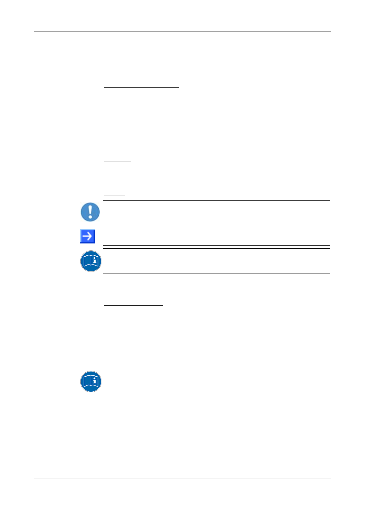
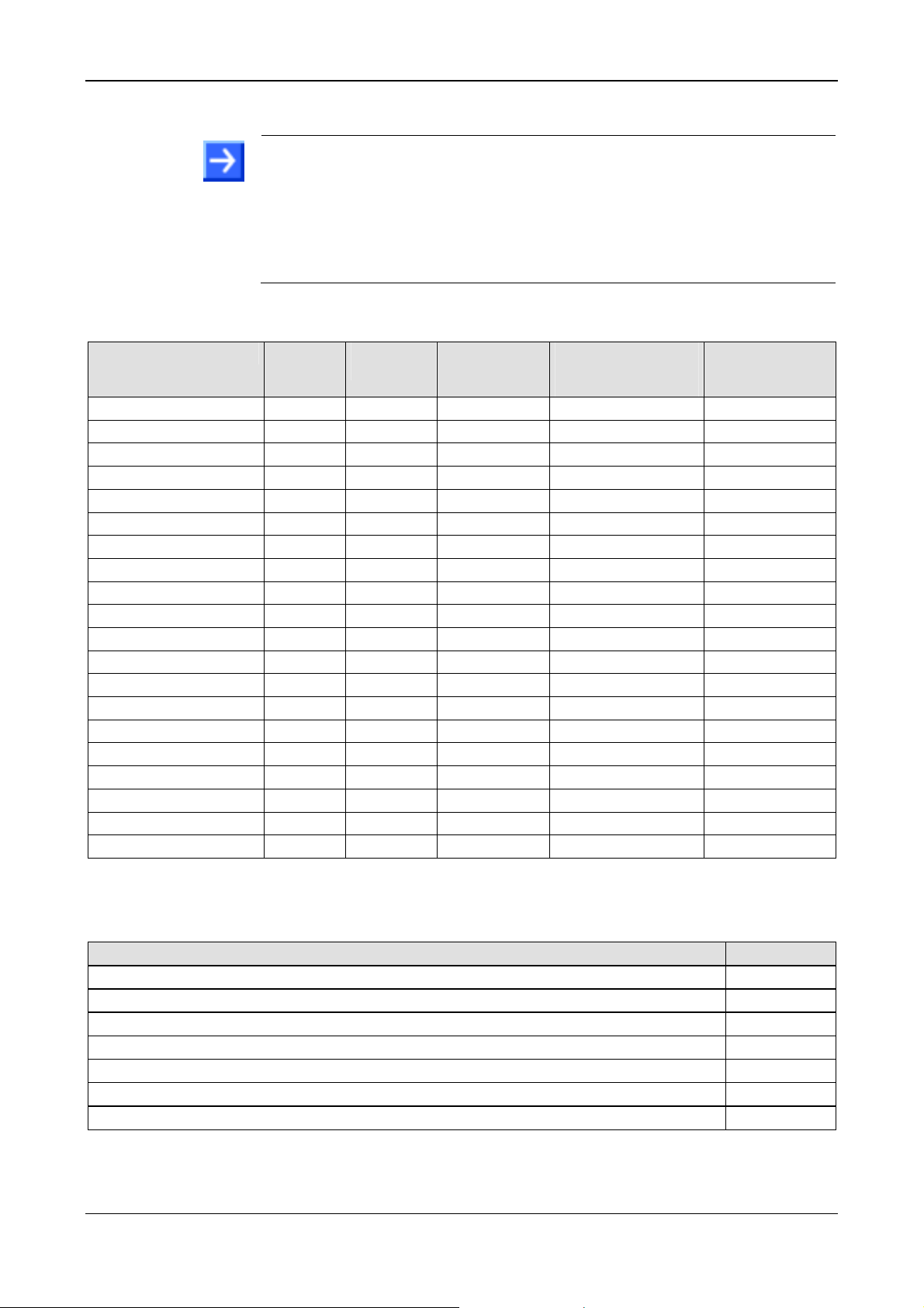
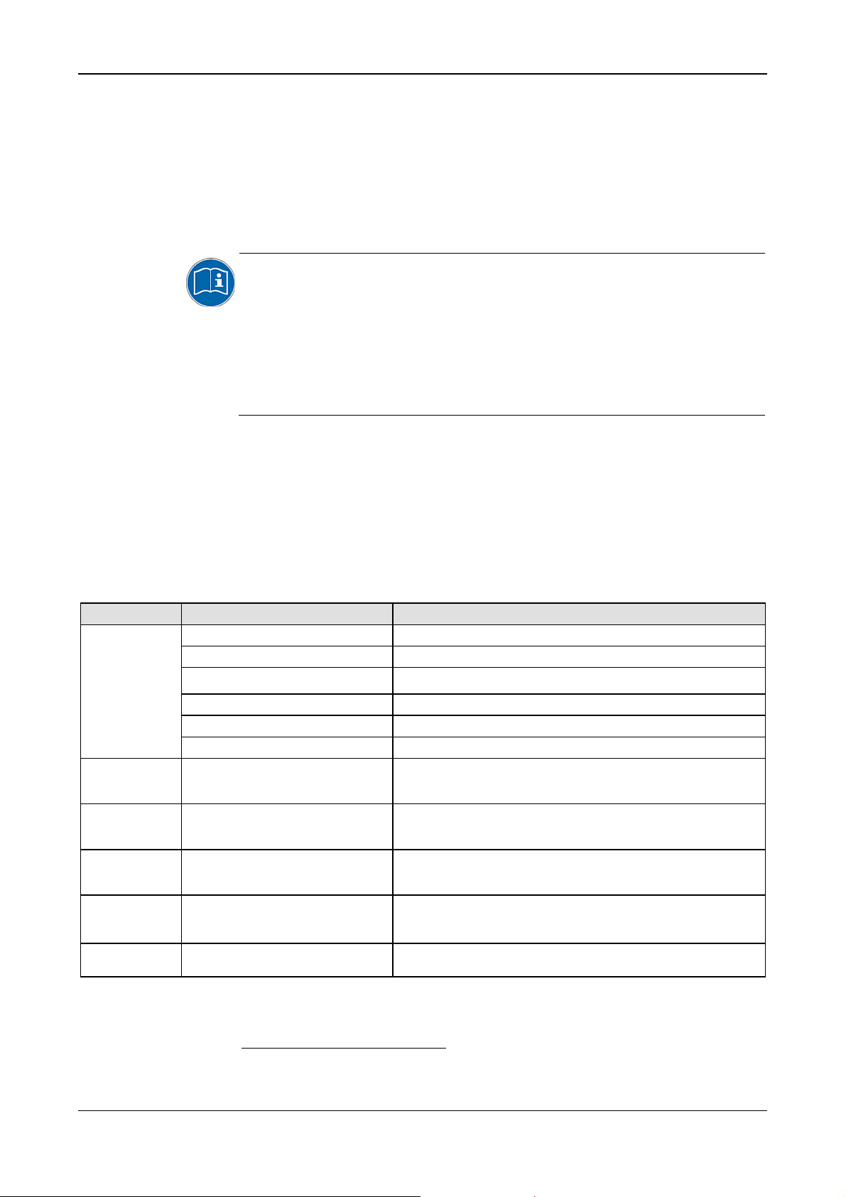
PC Cards cifX
PCI (CIFX 50)
PCI Express (CIFX 50E)
Low Profile PCI Express (CIFX 70E, CIFX 100EH)
Installation, Operation and Hardware Description
Hilscher Gesellschaft für Systemautomation mbH
www.hilscher.com
DOC120204UM36EN | Revision 36 | English | 2012-10 | Released | Public
Page 2

Table of Contents 2/145
Table of Contents
1 INTRODUCTION.........................................................................................................7
1.1 About the User Manual...............................................................................................7
1.1.1 Obligation to read and understand the Manual....................................................7
1.1.2 List of Revisions ...................................................................................................8
1.2 Legal Notes.................................................................................................................9
1.2.1 Copyright..............................................................................................................9
1.2.2 Important Notes....................................................................................................9
1.2.3 Exclusion of Liability...........................................................................................10
1.2.4 Warranty.............................................................................................................10
1.2.5 Export Regulations.............................................................................................11
1.2.6 Registered Trademarks......................................................................................11
1.2.7 EtherCAT Disclaimer..........................................................................................12
1.3 Licenses....................................................................................................................12
1.3.1 License Note about VARAN Client.....................................................................12
1.4 Conventions in this Manual.......................................................................................13
1.5 Reference on Hardware, Firmware, Software and Driver.........................................14
1.5.1 Hardware: PC Cards cifX ...................................................................................14
1.5.2 Reference on Driver and Software.....................................................................14
1.5.3 Reference on Firmware......................................................................................15
1.6 Contents of the Product DVD ...................................................................................16
1.6.1 Installation Guide, Documentation Overview.....................................................16
1.6.2 Device Description Files cifX..............................................................................16
1.7 Important Changes...................................................................................................17
1.7.1 PROFINET IO Device Firmware Versions 2.1 und 3.4......................................17
2 SAFETY ....................................................................................................................18
2.1 General Note ............................................................................................................18
2.2 Intended Use ............................................................................................................18
2.3 Personnel Qualification.............................................................................................18
2.4 Safety Instructions to avoid Personal Injury..............................................................19
2.4.1 Electrical Shock Hazard .....................................................................................19
2.5 Safety Instructions to avoid Property Damage .........................................................20
2.5.1 Device Destruction by exceeding allowed Supply Voltage ................................20
2.5.2 Device Destruction by exceeding allowed Signaling Voltage ............................21
2.5.3 Electrostatically sensitive Devices......................................................................21
2.6 Labeling of Safety Messages....................................................................................22
2.7 References Safety....................................................................................................22
3 DESCRIPTIONS AND REQUIREMENTS.................................................................
23
3.1 Description................................................................................................................23
3.1.1 Devices described in this Manual.......................................................................24
PC Cards cifX PCI, PCIe, Low Profile PCIe | Installation, Operation and Hardware Description
DOC120204UM36EN | Revision 36 | English | 2012-10 | Released | Public © Hilscher, 2008-2012
Page 3

Table of Contents 3/145
3.1.2 The Function „Slot Number (Card ID)“...............................................................24
3.1.3 The Function „IO-DMA Mode“............................................................................26
3.2 System Requirements ..............................................................................................27
3.2.1 Slot for the PC Cards cifX PCI, PCIe and Low Profile PCIe ..............................27
3.2.2 Supply Voltage and Signaling Voltage...............................................................27
3.2.3 System Requirements SYCON.net....................................................................28
3.2.4 System Requirements for netX Configuration Tool............................................28
3.3 Requirements for Operation of the PC Card cifX......................................................29
4 GETTING STARTED.................................................................................................30
4.1 Installation and Configuration PC Card cifX .............................................................30
4.2 Note on Exchange Service (Replacement Case) .....................................................33
4.3 Notes for the Configuration of the Master Device.....................................................33
4.4 Device Names in SYCON.net...................................................................................35
4.5 Update for Firmware, Driver and Software ...............................................................36
5 DEVICE DRAWINGS................................................................................................37
5.1 PC Cards cifX PCI and PCI Express ........................................................................37
5.1.1 Device Drawings CIFX 50-RE, CIFX 50E-RE....................................................37
5.1.2 Device Drawings CIFX 50-DP, CIFX 50E-DP....................................................39
5.1.3 Device Drawings CIFX 50-2DP..........................................................................41
5.1.4 Device Drawings CIFX 50-CO, CIFX 50E-CO...................................................42
5.1.5 Device Drawings CIFX 50-DN, CIFX 50E-DN....................................................44
5.1.6 Device Drawings CIFX 50-2ASM, CIFX 50E-2ASM ..........................................46
5.1.7 Device Drawings CIFX 50-CC, CIFX 50E-CC....................................................48
5.1.8 Device Drawings CIFX 50-CP, CIFX 50E-CP....................................................50
5.2 PC Cards cifX Low Profile PCI Express ...................................................................52
5.2.1 Device Drawings CIFX 70E-RE..........................................................................52
5.2.2 Device Drawings CIFX 100EH-RE\CUBE..........................................................53
5.2.3 Device Drawings CIFX 70E-DP..........................................................................54
5.2.4 Device Drawings CIFX 70E-CO.........................................................................55
5.2.5 Device Drawings CIFX 70E-DN .........................................................................56
6 HARDWARE INSTALLATION AND UNINSTALLING ...............................................
6.1 Safety Messages on Personal Injury........................................................................57
6.1.1 Electrical Shock Hazard .....................................................................................57
6.2 Property Damage Messages ....................................................................................58
6.2.1 Device Destruction by exceeding allowed Supply Voltage ................................58
6.2.2 Device Destruction by exceeding allowed Signaling Voltage ............................58
6.2.3 Electrostatically sensitive Devices......................................................................58
57
6.3 Fix Front Plate Sticker ..............................................................................................59
6.3.1 Fix Front Plate Sticker at CIFX 50-RE and CIFX 50E-RE..................................59
6.3.2 Fix Front Plate Sticker at CIFX 70E-RE, CIFX 100EH-RE\CUBE .....................60
6.4 Installing PC Card cifX PCI, PCIe, Low Profile PCIe................................................62
6.5 Uninstalling the PC Card cifX PCI, PCIe, Low Profile PCIe......................................63
PC Cards cifX PCI, PCIe, Low Profile PCIe | Installation, Operation and Hardware Description
DOC120204UM36EN | Revision 36 | English | 2012-10 | Released | Public © Hilscher, 2008-2012
Page 4

Table of Contents 4/145
7 TROUBLESHOOTING..............................................................................................64
7.1 Instructions for Problem Solving...............................................................................64
7.2 Failure in 10 MBit/s Half Duplex Mode and Workaround..........................................65
8 LED DESCRIPTIONS ...............................................................................................66
8.1 Overview LEDs Real-Time Ethernet Systems..........................................................66
8.2 Overview LEDs Fieldbus Systems............................................................................67
8.3 System LED..............................................................................................................67
8.4 EtherCAT Master......................................................................................................68
8.5 EtherCAT Slave........................................................................................................69
8.6 EtherNet/IP Scanner (Master) ..................................................................................70
8.7 EtherNet/IP Adapter (Slave).....................................................................................71
8.8 Open Modbus/TCP...................................................................................................72
8.9 Powerlink Controlled Node/Slave.............................................................................73
8.10 PROFINET IO-RT Controller....................................................................................74
8.11 PROFINET IO-RT Device.........................................................................................75
8.12 sercos Master...........................................................................................................76
8.13 sercos Slave.............................................................................................................77
8.14 VARAN Client (Slave)...............................................................................................78
8.15 PROFIBUS DP Master.............................................................................................79
8.16 PROFIBUS DP Slave...............................................................................................79
8.17 PROFIBUS MPI Device............................................................................................80
8.18 CANopen Master......................................................................................................81
8.19 CANopen Slave........................................................................................................82
8.20 DeviceNet Master.....................................................................................................83
8.21 DeviceNet Slave.......................................................................................................83
8.22 AS Interface Master..................................................................................................84
8.23 CC-Link Slave...........................................................................................................84
8.24 CompoNet Slave.......................................................................................................85
9 DEVICE CONNECTIONS AND SWITCHES.............................................................
9.1 Ethernet Interface.....................................................................................................86
9.1.1 Ethernet Pin Assignment at the RJ45 Socket....................................................86
9.1.2 Ethernet Connection Data..................................................................................87
9.1.3 Use of Hubs and Switches.................................................................................87
86
9.2 PROFIBUS Interface ................................................................................................88
9.3 CANopen Interface...................................................................................................88
9.4 DeviceNet Interface..................................................................................................89
9.5 AS-Interface Interface...............................................................................................89
9.6 CC-Link Interface......................................................................................................90
PC Cards cifX PCI, PCIe, Low Profile PCIe | Installation, Operation and Hardware Description
DOC120204UM36EN | Revision 36 | English | 2012-10 | Released | Public © Hilscher, 2008-2012
Page 5

Table of Contents 5/145
9.7 CompoNet Interface..................................................................................................90
9.8 Rotary Switch for Slot Number (Card ID)..................................................................91
9.8.1 Set Slot Number (Card ID).................................................................................91
9.8.2 Note for Device Exchange Service (Replacement Case):.................................91
9.8.3 Rotary Switch Slot Number PC Cards cifX Low Profile......................................92
9.9 SYNC Connector (Pin-Assignment, Hardware/Firmware)........................................93
9.9.1 Pin Assignment SYNC Connector, X51 (CIFX 50 50E 70E)..............................93
9.9.2 Pin Assignment SYNC Connector, J3 (CIFX 100EH)........................................93
9.9.3 Items on Hardware.............................................................................................94
9.9.4 Items on Firmware..............................................................................................94
9.10 Pin Assignment at the Bus........................................................................................95
9.10.1 Overview on the Pin Assignment at the Bus......................................................95
9.10.2 References to the Bus Specifications PCI, PCI Express ...................................95
9.10.3 Pin Assignment for PCI Express Bus CIFX 100EH-RE\CUBE..........................96
10 TECHNICAL DATA ...................................................................................................97
10.1 Technical Data PC Cards cifX..................................................................................97
10.1.1 CIFX 50-RE........................................................................................................97
10.1.2 CIFX 50-DP........................................................................................................98
10.1.3 CIFX 50-2DP......................................................................................................98
10.1.4 CIFX 50-CO........................................................................................................99
10.1.5 CIFX 50-DN........................................................................................................99
10.1.6 CIFX 50-2ASM .................................................................................................100
10.1.7 CIFX 50-CC......................................................................................................100
10.1.8 CIFX 50-CP......................................................................................................101
10.1.9 CIFX 50E-RE....................................................................................................102
10.1.10 CIFX 50E-DP....................................................................................................103
10.1.11 CIFX 50E-CO ...................................................................................................103
10.1.12 CIFX 50E-DN....................................................................................................104
10.1.13 CIFX 50E-2ASM...............................................................................................104
10.1.14 CIFX 50E-CC....................................................................................................105
10.1.15 CIFX 50E-CP....................................................................................................105
10.1.16 CIFX 70E-RE....................................................................................................106
10.1.17 CIFX 100EH-RE\CUBE....................................................................................107
10.1.18 CIFX 70E-DP....................................................................................................108
10.1.19 CIFX 70E-CO ...................................................................................................108
10.1.20 CIFX 70E-DN....................................................................................................109
10.2 PCI IDs PC Cards cifX on the PCI Bus...................................................................110
10.3 Supported PCI-Bus Commands .............................................................................110
10.4 Technical Data of the Communication Protocols....................................................111
10.4.1 EtherCAT Master..............................................................................................111
10.4.2 EtherCAT Slave................................................................................................112
10.4.3 EtherNet/IP Scanner (Master)..........................................................................113
10.4.4 EtherNet/IP Adapter (Slave).............................................................................114
10.4.5 Open Modbus/TCP...........................................................................................115
10.4.6 Powerlink Controlled Node/Slave.....................................................................115
10.4.7 PROFINET IO-RT Controller............................................................................116
PC Cards cifX PCI, PCIe, Low Profile PCIe | Installation, Operation and Hardware Description
DOC120204UM36EN | Revision 36 | English | 2012-10 | Released | Public © Hilscher, 2008-2012
Page 6

Table of Contents 6/145
10.4.8 PROFINET IO-RT Device ................................................................................117
10.4.9 sercos Master...................................................................................................118
10.4.10 sercos Slave.....................................................................................................119
10.4.11 VARAN Client (Slave).......................................................................................120
10.4.12 PROFIBUS DP Master.....................................................................................121
10.4.13 PROFIBUS DP Slave.......................................................................................122
10.4.14 PROFIBUS MPI................................................................................................123
10.4.15 CANopen Master..............................................................................................124
10.4.16 CANopen Slave................................................................................................125
10.4.17 DeviceNet Master.............................................................................................126
10.4.18 DeviceNet Slave...............................................................................................127
10.4.19 AS-Interface Master..........................................................................................128
10.4.20 CC Link Slave...................................................................................................129
10.4.21 CompoNet Slave ..............................................................................................130
11 ANNEX....................................................................................................................131
11.1 Matrix Label............................................................................................................131
11.2 EtherCAT Summary over Vendor ID, Conformance test, Membership and Network
Logo........................................................................................................................
11.2.1 Vendor ID .........................................................................................................131
11.2.2 Conformance....................................................................................................132
11.2.3 Certified Product vs. Certified Network Interface.............................................132
11.2.4 Membership and Network Logo .......................................................................132
131
11.3 Disposal of Waste Electronic Equipment................................................................133
11.4 References.............................................................................................................133
11.5 List of Figures.........................................................................................................134
11.6 List of Tables..........................................................................................................135
11.7 Glossary..................................................................................................................138
11.8 Contacts..................................................................................................................145
PC Cards cifX PCI, PCIe, Low Profile PCIe | Installation, Operation and Hardware Description
DOC120204UM36EN | Revision 36 | English | 2012-10 | Released | Public © Hilscher, 2008-2012
Page 7

Introduction 7/145
1 Introduction
1.1 About the User Manual
This user manual provides descriptions of the installation, operation and
hardware of the PC Cards cifX PCI, PCI Express and Low Profile PCI
Express under Windows
subsequently.
PC Cards cifX:
PCI (CIFX50),
PCI Express (CIFX 50E),
Low Profile PCI Express (CIFX 70E, CIFX 100EH-RE\CUBE*)
*only Real-Time Ethernet
for the Real-Time Ethernet systems: for the fieldbus systems:
®
XP, Windows® Vista and Windows® 7 as listed
EtherCAT
EtherNet/IP
Open-Modbus/TCP
Powerlink
PROFINET IO-RT
sercos
VARAN
For information about the Installation of the Software refer to the User Manual „Software
Installation for PC Cards cifX“ [DOC120207UMXXEN].
For information about the Wiring of the Protocol Interface refer to the „Wiring
Instructions“ [DOC120208UMXXEN].
The devices described in this manual are listed in the sections Devices described in this
Manual (page
Installation and Uninstalling (page
and Switches (page
24). The devices are described in detail in the chapters Hardware
57), LED Descriptions (page 66), Device Connections
86) and Technical Data (page 97).
PROFIBUS DP
PROFIBUS MPI
CANopen
DeviceNet
AS-Interface
CC-Link
CompoNet
1.1.1 Obligation to read and understand the Manual
Important!
To avoid personal injury and to avoid property damage to your system
or to your PC card, you must read and understand all instructions in the
manual and all accompanying texts to your PC card, before installing
and operating your PC card.
First read the Safety Instructions in the safety chapter.
Obey to all Safety Messages in the manual.
Keep the product DVD providing the product manuals.
PC Cards cifX PCI, PCIe, Low Profile PCIe | Installation, Operation and Hardware Description
DOC120204UM36EN | Revision 36 | English | 2012-10 | Released | Public © Hilscher, 2008-2012
Page 8

Introduction 8/145
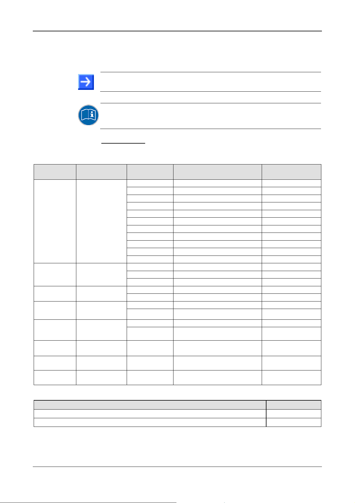
1.1.2 List of Revisions
Index Date Chapter Revisions
33 12-02-06 All
34 12-03-13
35 12-07-04
36 12-10-01
3.3, 4.1,
9.1.3
5,
5.1.7,
5.1.8,
8.2, 8.22,
8.5,
9.10.3,
10.1,
10.4.4,
10.4.10,
10.4.15
8.20, 8.21,
10.1,
10.4.10
Table 1: List of Revisions
User Manuals „PC Cards cifX Real-Time Ethernet“ [DOC060501UM32EN]
and „PC Cards cifX PROFIBUS DP, CANopen, DeviceNet, AS-Interface,
CompoNet, CC-Link“ [DOC080201UM23EN] split in:
- „PC Cards cifX PCI (CIFX 50), PCI Express (CIFX 50E), Low Profile PCI
Express (CIFX 70E, CIFX 100EH)“ [DOC120204UM33EN] ,
- „PC Cards cifX Compact PCI (CIFX80), Mini PCI (CIFX90), Mini PCI
Express (CIFX 90E), PCI-104 (CIFX 104C)“ [DOC120205UM33EN] ,
- „PC Cards cifX PC/104 (CIFX 104), [DOC120206UM33EN],
- „Software Installation for PC Cards cifX“ [DOC120207UM33EN] ,
- „Wiring Instructions“ [DOC120208UM01EN] .
PC Cards cifX Low Profile PCI Express (CIFX 70E-RE, CIFX 70E-DP, CIFX
70E-CO, CIFX 70E-DN) added.
Note how to use the Software added in the sections Requirements for
Operation of the PC Card cifX and
cifX. Section
Section
CIFX 50-2DP added, indication for the fieldbus interfaces for 2-channel
devices changed to “channel 0” and “channel 1”, as it is displayed in
SYCON.net Device Assignment ,
Sections
CIFX 50-CP, CIFX 50E-CP revised (current card layout).
Sections Overview LEDs Fieldbus Systems and AS Interface Master revised
(ibidem, indication for the fieldbus interfaces for 2-channel devices changed to
“channel 0” and “channel 1”).
LED description in section
Section
B10) revised.
Section Technical Data PC Cards cifX Dimensions (L x W x D) for CIFX 50CC/CP 120 x 85,4
Technical data protocols updated in the sections
sercos Slave,
and
CANopen Master.
Sections DeviceNet Master and DeviceNet Slave updated.
Section
Section
(1.) S/IP protocol is now supported,
(2.) Maximum number of cyclic input or output data (Tx) of all Slaves
(netx100, netx500) 128 bytes (including Connection Control and IO Status) ,
(3.) Maximum number of slave devices: 8 (now no limitation for netX100/500
any more)
Use of Hubs and Switches updated.
Device Drawings revised and completed (drawing for front plate for
Device Drawings CIFX 50-CC, CIFX 50E-CC and Device Drawings
EtherCAT Slave updated,
Pin Assignment for PCI Express Bus CIFX 100EH-RE\CUBE (Pin
x 18,5 mm, for CIFX 50E-CC/CP 120 x 89,9 x 18,5 mm,
Technical Data PC Cards cifX revised.
sercos Slave updated (reference to firmware/stack version V3.1.x.x):
Installation and Configuration PC Card
EtherNet/IP Adapter (Slave)
PC Cards cifX PCI, PCIe, Low Profile PCIe | Installation, Operation and Hardware Description
DOC120204UM36EN | Revision 36 | English | 2012-10 | Released | Public © Hilscher, 2008-2012
Page 9

Introduction 9/145
1.2 Legal Notes
1.2.1 Copyright
© Hilscher, 2008-2012, Hilscher Gesellschaft für Systemautomation mbH
All rights reserved.
The images, photographs and texts in the accompanying material (user
manual, accompanying texts, documentation, etc.) are protected by
German and international copyright law as well as international trade and
protection provisions. You are not authorized to duplicate these in whole or
in part using technical or mechanical methods (printing, photocopying or
other methods), to manipulate or transfer using electronic systems without
prior written consent. You are not permitted to make changes to copyright
notices, markings, trademarks or ownership declarations. The included
diagrams do not take the patent situation into account. The company
names and product descriptions included in this document may be
trademarks or brands of the respective owners and may be trademarked or
patented. Any form of further use requires the explicit consent of the
respective rights owner.
1.2.2 Important Notes
The user manual, accompanying texts and the documentation were created
for the use of the products by qualified experts, however, errors cannot be
ruled out. For this reason, no guarantee can be made and neither juristic
responsibility for erroneous information nor any liability can be assumed.
Descriptions, accompanying texts and documentation included in the user
manual do not present a guarantee nor any information about proper use
as stipulated in the contract or a warranted feature. It cannot be ruled out
that the user manual, the accompanying texts and the documentation do
not correspond exactly to the described features, standards or other data of
the delivered product. No warranty or guarantee regarding the correctness
or accuracy of the information is assumed.
We reserve the right to change our products and their specification as well
as related user manuals, accompanying texts and documentation at all
times and without advance notice, without obligation to report the change.
Changes will be included in future manuals and do not constitute any
obligations. There is no entitlement to revisions of delivered documents.
The manual delivered with the product applies.
Hilscher Gesellschaft für Systemautomation mbH is not liable under any
circumstances for direct, indirect, incidental or follow-on damage or loss of
earnings resulting from the use of the information contained in this
publication.
PC Cards cifX PCI, PCIe, Low Profile PCIe | Installation, Operation and Hardware Description
DOC120204UM36EN | Revision 36 | English | 2012-10 | Released | Public © Hilscher, 2008-2012
Page 10

Introduction 10/145
1.2.3 Exclusion of Liability
The software was produced and tested with utmost care by Hilscher
Gesellschaft für Systemautomation mbH and is made available as is. No
warranty can be assumed for the performance and flawlessness of the
software for all usage conditions and cases and for the results produced
when utilized by the user. Liability for any damages that may result from the
use of the hardware or software or related documents, is limited to cases of
intent or grossly negligent violation of significant contractual obligations.
Indemnity claims for the violation of significant contractual obligations are
limited to damages that are foreseeable and typical for this type of contract.
It is strictly prohibited to use the software in the following areas:
• for military purposes or in weapon systems;
• for the design, construction, maintenance or operation of nuclear
facilities;
• in air traffic control systems, air traffic or air traffic communication
systems;
• in life support systems;
• in systems in which failures in the software could lead to personal injury
or injuries leading to death.
We inform you that the software was not developed for use in dangerous
environments requiring fail-proof control mechanisms. Use of the software
in such an environment occurs at your own risk. No liability is assumed for
damages or losses due to unauthorized use.
1.2.4 Warranty
Although the hardware and software was developed with utmost care and
tested intensively, Hilscher Gesellschaft für Systemautomation mbH does
not guarantee its suitability for any purpose not confirmed in writing. It
cannot be guaranteed that the hardware and software will meet your
requirements, that the use of the software operates without interruption and
that the software is free of errors. No guarantee is made regarding
infringements, violations of patents, rights of ownership or the freedom from
interference by third parties. No additional guarantees or assurances are
made regarding marketability, freedom of defect of title, integration or
usability for certain purposes unless they are required in accordance with
the law and cannot be limited. Warranty claims are limited to the right to
claim rectification.
PC Cards cifX PCI, PCIe, Low Profile PCIe | Installation, Operation and Hardware Description
DOC120204UM36EN | Revision 36 | English | 2012-10 | Released | Public © Hilscher, 2008-2012
Page 11

Introduction 11/145
1.2.5 Export Regulations
The delivered product (including the technical data) is subject to export or
import laws as well as the associated regulations of different counters, in
particular those of Germany and the USA. The software may not be
exported to countries where this is prohibited by the United States Export
Administration Act and its additional provisions. You are obligated to
comply with the regulations at your personal responsibility. We wish to
inform you that you may require permission from state authorities to export,
re-export or import the product.
1.2.6 Registered Trademarks
Windows® XP, Windows® Vista and Windows® 7 are registered trademarks
of Microsoft Corporation.
Linux is a registered trademark of Linus Torvalds.
QNX is a registered trademark of QNX Software Systems, Ltd.
VxWorks is a registered trademark of Wind River Systems, Inc.
IntervalZero RTX ™ is a trademark of IntervalZero.
®
Adobe-Acrobat
is a registered trademark of the Adobe Systems
Incorporated.
®
CANopen
is a registered trademark of CAN in AUTOMATION -
International Users and Manufacturers Group e.V (CiA), Nürnberg.
®
CC-Link
is a registered trademark of Mitsubishi Electric Corporation,
Tokyo, Japan.
CompoNet
®
, DeviceNet
®
und EtherNet/IP® are trademarks of ODVA (Open
DeviceNet Vendor Association, Inc).
®
EtherCAT
Beckhoff Automation GmbH, Verl, Germany
is a registered trademark and a patented technology of
, formerly Elektro Beckhoff
GmbH.
®
EtherNet/IP
is a trademark of ODVA (Open DeviceNet Vendor
Association, Inc).
Modbus
®
is a registered trademark of Schneider Electric.
MPI is a registered trademark of Siemens AG, Berlin and Munich.
Powerlink is a registered trademark of B&R, Bernecker + Rainer Industrie-
Elektronik Ges.m.b.H, Eggelsberg, Austria
PROFIBUS und PROFINET are registered trademarks of PROFIBUS
International, Karlsruhe.
®
sercos interface
Suessen, Germany.
is a registered trademark of sercos International e. V.,
PCI, PCI Express, and PCIe are trademarks or registered trademarks of
PCI-SIG.
All other mentioned trademarks are property of their respective legal
owners.
PC Cards cifX PCI, PCIe, Low Profile PCIe | Installation, Operation and Hardware Description
DOC120204UM36EN | Revision 36 | English | 2012-10 | Released | Public © Hilscher, 2008-2012
Page 12

Introduction 12/145
1.2.7 EtherCAT Disclaimer
EtherCAT® is registered trademark and patented technology, licensed by
Beckhoff Automation GmbH, Germany.
To get details and restrictions regarding using the EtherCAT technology
refer to the following documents:
“EtherCAT Marking rules”
“EtherCAT Conformance Test Policy”
“EtherCAT Vendor ID Policy”
These documents are available at the ETG homepage www.ethercat.org
or directly over
info@ethercat.org.
A summary over Vendor ID, Conformance test, Membership and Network
Logo can be found within the appendix section of this document under
section
EtherCAT Summary over Vendor ID, Conformance test,
Membership and Network Logo on page
1.3 Licenses
If a PC Card cifX is used as a Slave, neither for the firmware nor for the
configuration software SYCON.net a license is required.
Licenses will be required if the PC Card cifX is used with
• a firmware with master functionality*.
* The master license includes the PC Card cifX operating as master and
the license for the configuration software SYCON.net for the respective
cifX.
1.3.1 License Note about VARAN Client
In order to use the PC Card cifX with VARAN, you need a license which
you can acquire at the VNO (VARAN Bus-Nutzerorganisation, Bürmooser
Straße 10, A-5112 Lamprechtshausen, info@varan-bus.net) after getting a
member of VON.
131.
The license as well as the Vendor ID and the Device ID can be adjusted
with the SYCON.net configuration software or with the netX Configuration
Tool.
PC Cards cifX PCI, PCIe, Low Profile PCIe | Installation, Operation and Hardware Description
DOC120204UM36EN | Revision 36 | English | 2012-10 | Released | Public © Hilscher, 2008-2012
Page 13
Introduction 13/145
1.4 Conventions in this Manual
Operation instructions, a result of an operation step or notes are marked as
follows:
Operation Instructions:
¾
<instruction>
or
1. <instruction>
2. <instruction>
Results:
°
<result>
Notes:
Important: <important note>
Note: <note>
<note, where to find further information>
Used Terminology
PC Card cifX
Communication Interfaces
of the cifX family of Hilscher
based on the netX technology.
CIFX 50-RE Example for the product name for a PC card cifX Real-Time
Ethernet.
CIFX 50-DP Example for the product name for a PC card cifX
PROFIBUS DP.
For further terminology to the PC cards cifX, its installation, configuration
and operation refer to section
Glossary on page 138.
PC Cards cifX PCI, PCIe, Low Profile PCIe | Installation, Operation and Hardware Description
DOC120204UM36EN | Revision 36 | English | 2012-10 | Released | Public © Hilscher, 2008-2012
Page 14
Introduction 14/145
1.5 Reference on Hardware, Firmware, Software and Driver
Note on Software Update: The hardware revisions and the versions for
the firmware, the driver or the configuration software listed in this section
functionally belong together. For existing hardware installation the
firmware, the driver and the configuration software must be updated
according to the details listed in this section.
For the software upgrade system overview refer to section
Firmware, Driver and Software on page
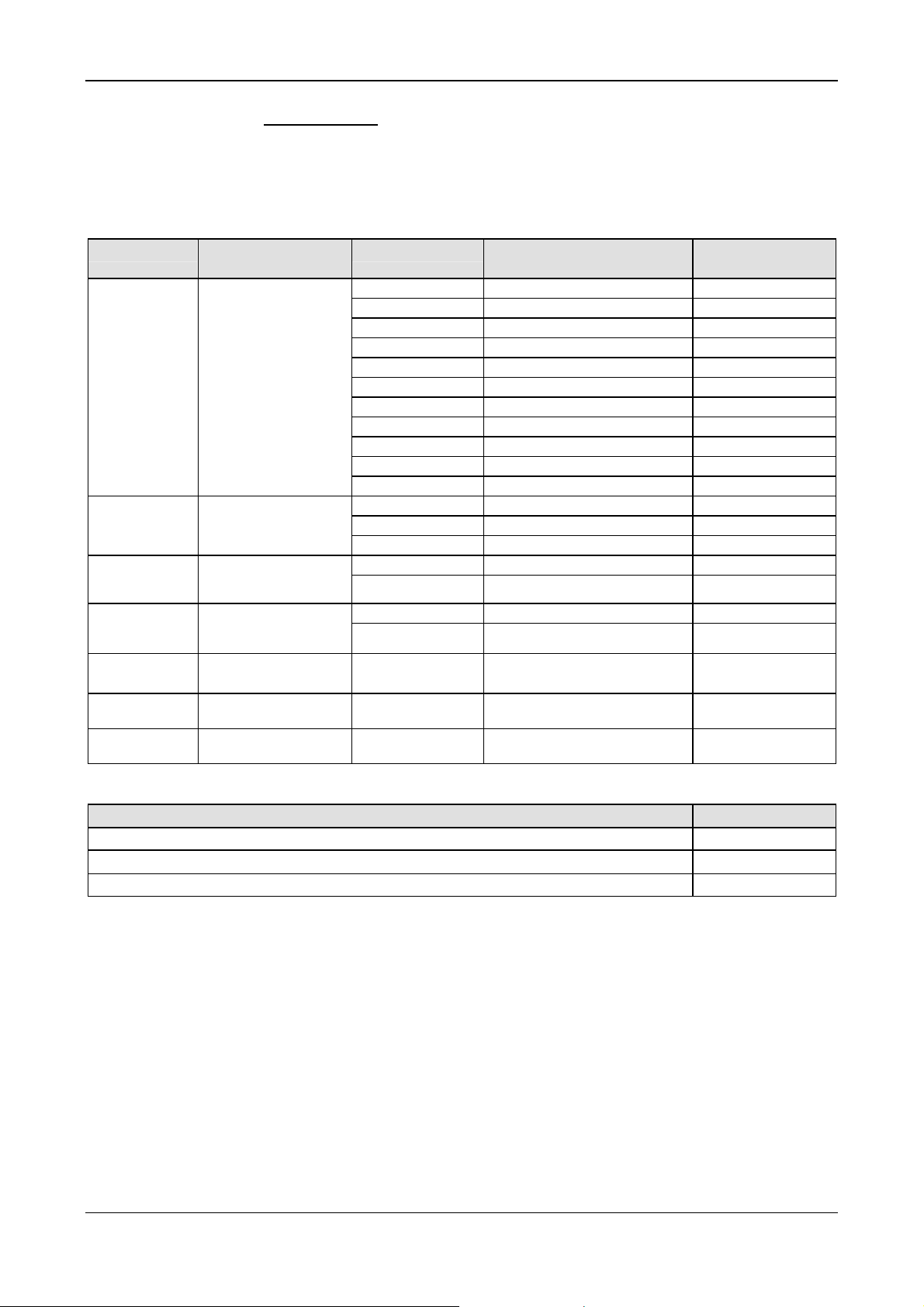
1.5.1 Hardware: PC Cards cifX
36.
Update for
PC Card cifX Part No.
CIFX 50-RE 1250.100 5 - 3 1
CIFX 50-DP 1250.410 5 - 5 1
CIFX 50-2DP 1252.410 2 - - 1
CIFX 50-CO 1250.500 5 - 5 1
CIFX 50-DN 1250.510 5 - 5 1
CIFX 50-2ASM 1252.630 2 - 2 1
CIFX 50-CC 1250.740 2 - 2 1
CIFX 50-CP 1250.750 2 - 2 1
CIFX 50E-RE 1251.100 5 - 4 4
CIFX 50E-DP 1251.410 6 - 5 5
CIFX 50E-CO 1251.500 5 - 4 4
CIFX 50E-DN 1251.510 5 - 4 4
CIFX 50E-2ASM 1253.630 5 - 2 4
CIFX 50E-CC 1251.740 4 - 3 3
CIFX 50E-CP 1251.750 4 - 3 3
CIFX 70E-RE 1.259.100 1 - 1 1
CIFX 100EH-RE\CUBE 9016.090 4 - 1
CIFX 70E-DP 1.259.410 1 - 1 1
CIFX 70E-CO 1.259.500 1 - 1 1
CIFX 70E-DN 1.259.510 1 - 1 1
Table 2: Reference on Hardware PC Cards cifX
Hardware
Revision
USB
from HW Rev.
„Rotary Switch Slot
Number (Card ID)“
from HW Rev.
„IO-DMA Mode“
from HW Rev.
1
1.5.2 Reference on Driver and Software
Driver and Software Version
SYCON.net
netX Configuration Tool-Setup
cifX Device Driver
Bootloader (is included in the cifX Device Driver Setup)
Toolkit
cifX TCP/IP Server for SYCON.net
US Driver
Table 3: Reference on Driver and Software
PC Cards cifX PCI, PCIe, Low Profile PCIe | Installation, Operation and Hardware Description
DOC120204UM36EN | Revision 36 | English | 2012-10 | Released | Public © Hilscher, 2008-2012
SYCONnet netX setup.exe
netXConfigurationUtility_Setup.exe
cifX Device Driver Setup.exe
1.1.x.x
cifX TCP Server.exe
USB Driver of Windows
®
V1.350.x.x
1.0502.x.x
1.1.x.x
V1.3.x.x
V2.1.0.0
5.1.2600.x
Page 15

Introduction 15/145
1.5.3 Reference on Firmware
Firmware File Fieldbus System Firmware Version Minimum Version of the Firmware
CIFXECM.NXF EtherCAT Master 3.0.x.x from 2.4.4.0
CIFXECS.NXF EtherCAT Slave 2.5. x.x from 2.5.13.0
CIFXEIM.NXF EtherNet/IP Scanner 2.4. x.x from 2.2.4.1
CIFXEIS.NXF EtherNet/IP Adapter 2.6. x.x from 2.3.4.1
CIFXOMB.NXF Open-Modbus/TCP 2.5. x.x from 2.3.2.1
CIFXPLS.NXF POWERLINK Controlled Node 2.1. x.x from 2.1.22.0
CIFXPNM.NXF PROFINET IO Controller 2.6. x.x from 2.4.10.0
CIFXPNS.NXF PROFINET IO Device
CIFXS3M.NXF sercos Master 2.0.x.x from 2.0.14.0
CIFXS3S.NXF sercos Slave 3.0.x.x from 3.0.13.0
CIFXVRS.NXF VARAN Client 1.0.x.x from 1.0.3.0
CIFXDPM.NXF PROFIBUS DP Master 2.5.x.x from 2.3.22.0
CIFX2DPM.NXF PROFIBUS DP Master,
2 Channels
CIFXDPS.NXF PROFIBUS DP Slave 2.4.x.x from 2.3.30.0
CIFX2DPS.NXF PROFIBUS DP Slave,
2 Channels
CIFXMPI.NXF PROFIBUS MPI Device 2.4.x.x from 2.4.1.2
CIFXCOM.NXF CANopen Master 2.9.x.x from 2.5.2.0
CIFXCOS.NXF CANopen Slave 3.2.x.x from 2.4.4.0
CIFXDNM.NXF DeviceNet Master 2.3.x.x from 2.2.7.0
CIFXDNS.NXF DeviceNet Slave 2.3.x.x from 2.2.7.0
CIFX2ASM.NXF AS-Interface Master, 2 Channels 2.3.x.x CIFXCCS.NXF CC-Link Slave 2.7.x.x CIFXCPS.NXF CompoNet Slave 1.0.x.x -
Table 4: Reference on Firmware
2.1.45.x (V2)*,
3.4.x.x (V3)
2.5.x.x -
2.4.x.x -
for USB Support
-
from 3.4.9.0
The downloadable cifX firmware runs on PC Cards cifX PCI, PCI Express
and Low Profile PCI Express. The firmware automatically detects whether it
is running on a PC Cards cifX PCI, PCI Express or Low Profile PCI
Express.
PC Cards cifX PCI, PCIe, Low Profile PCIe | Installation, Operation and Hardware Description
DOC120204UM36EN | Revision 36 | English | 2012-10 | Released | Public © Hilscher, 2008-2012
Page 16
Introduction 16/145
1.6 Contents of the Product DVD
On the Communication Solutions DVD you will find these installation
instructions about the software installation and the necessary configuration
software, the documentation, the drivers and software for your PC Card
cifX, and additional auxiliary tools.
1.6.1 Installation Guide, Documentation Overview
The installation guide Software Installation and Documentation Overview on the Communication Solutions DVD are in the directory
Documentation\0. Installation and Overview. The installation guide
includes:
An overview on the Content of the Communication Solutions DVD (in
the section What is on the Communication Solutions DVD?)
Overviews listing the available Documentations for PC cards cifX (in
chapter PC Cards cifX, Software and Documentation).
1.6.2 Device Description Files cifX
The Communication Solutions DVD EDS directory includes the device
description files for the PC Cards cifX. The device description file is
required to configure the used Master device. The Real-Time Ethernet
system Open Modbus/TCP does not use device description files. The
description files for the EtherNet/IP Master device is needed, when an
additional EtherNet/IP Master device shall communicate to a Hilscher
EtherNet/IP Master device via EtherNet/IP.
PC Cards cifX System File Name of the Device Description File
CIFX 50-RE,
CIFX 50E-RE,
CIFX 70E-RE,
CIFX 100EHRE\CUBE
CIFX 50-DP,
CIFX 50E-DP,
CIFX 70E-DP
CIFX 50-CO,
CIFX 50E-CO,
CIFX 70E-CO
CIFX 50-DN,
CIFX 50E-DN,
CIFX 70E-DN
CIFX 50-CC,
CIFX 50E-CC
CIFX 50-CP,
CIFX 50E-CP
EtherCAT Slave Hilscher cifX RE ECS V2.2.x.xml (or with extension DDF)
EtherNet/IP Adapter (Slave)
EtherNet/IP Scanner (Master) HILSCHER CIFX-RE EIM V1.0.eds
Powerlink Controlled Node/Slave
PROFINET IO-RT Device
sercos Slave
PROFIBUS DP Slave HIL_0B69.GSD
CANopen Slave CIFX CO COS.eds
DeviceNet Slave CIFX_DN_DNS.EDS
CC-Link Slave cifx-ccs_1.csp, cifx-ccs_2.csp, cifx-ccs_3.csp, cifx-ccs_4.csp,
CompoNet Slave CIFX_CP_CPS.eds
Table 5: Device Description Files for PC Cards cifX
HILSCHER CIFX-RE EIS V1.1.EDS
00000044_cifX RE PLS.xdd
GSDML-V2.2-HILSCHER-CIFX RE PNS-20110413.xml
Hilscher CIFX RE S3S xxx.xml
(for one, two, three or four Remote Device Station),
cifx-ccs_io.csp (for one Remote IO Device Station)
1
1
For the PROFINET IO Device Firmware with V3.4.19.0 the GSDML-V2.2-
HILSCHER-CIFX RE PNS-20110413.xml is provided.
PC Cards cifX PCI, PCIe, Low Profile PCIe | Installation, Operation and Hardware Description
DOC120204UM36EN | Revision 36 | English | 2012-10 | Released | Public © Hilscher, 2008-2012
Page 17
Introduction 17/145
1.7 Important Changes
All current version information for hardware and software described in this
manual are provided in the folder \Documentation\What's New -
Communication Solutions DVD RL XX EN.pdf on the Communication
Solutions DVD.
1.7.1 PROFINET IO Device Firmware Versions 2.1 und 3.4
The PROFINET IO Device firmware was revised and expanded and is
available in version 3.4.x.x since June 2010. The PROFINET IO Device
firmware V3.4.x.x compared to V2.1.x.x has the following main changes:
• IRT (Class 3 synchronized) is supported (only for netX 100/500)
• ChannelInit is also supported now (V2.1.x.x supports only SystemReset)
• The API was revised and is only compatible regarding cyclic data
exchange.
If you want to change to V3.4.x.x, then you can read in the PROFINET IO
Device Migration Guide which changes are necessary in the application
program to use version 3.4.x.x.
SYCON.net V1.210.x.x and V1.300.x.x can configure PROFINET IO Device
Firmware V2.1.x.x as well as V3.4.x.x.
The development of the PROFINET IO Device firmware V2.1.x.x will not be
continued and delivered.
On the Communication Solutions DVD are both versions V3.4.x.x and
V2.1.x.x available in the directory firmware.
PROFINET IO Device V3 (Directory on the DVD \ File) PROFINET IO De vice V2 (only on request)
Firmware
Header
GSDML
Protocol API
Firmware\CIFX\cifxpns.nxf cifxpns.nxf*
API\Header\Firmware\PROFINET IO IRT RT Device V3 PROFINET IO RT Device V2
DVD:\EDS\PROFINET\GSDML-V2.2-HILSCHER-CIFX
RE PNS-20110413xml
API\Protocol\PROFINET IO IRT RT Device V3\
PROFINET IO RT IRT Device Protocol API xx EN.pdf
Migration Guide: PROFINET IO Device - Version 2 to
Version 3 MG xx EN.pdf
Table 6: PROFINET IO Device Firmware Version 2.1 and 3.4, further Header, GSDML and
Protocol API
2
GSDML-V2.1-HILSCHER-CIFX RE PNS-20081210.xml
PROFINET IO RT Device V2 Protocol API xx EN.pdf
Important! The PROFINET IO Device Firmware V2.1.x.x cannot be
configured by the netX Configuration Tool from version 1.0500.1.1564 on
any more, but only the PROFINET IO Device firmware versions from
V3.x.x.x on and higher. The firmware version 2.1.x.x can only be
configured with the netX Configuration Tool up to the Version
1.0500.1.1564.
2
For the PROFINET IO Device Firmware with V3.4.19.0 the GSDML-V2.2-
HILSCHER-CIFX RE PNS-20110413.xml is provided.
PC Cards cifX PCI, PCIe, Low Profile PCIe | Installation, Operation and Hardware Description
DOC120204UM36EN | Revision 36 | English | 2012-10 | Released | Public © Hilscher, 2008-2012
Page 18
Safety 18/145
2 Safety
2.1 General Note
The documentation in the form of a user manual, an operating instruction
manual or other manual types, as well as the accompanying texts have
been created for the use of the products by educated personnel. When
using the products, all Safety Messages, Safety Messages, Property
Damage Messages and all valid legal regulations have to be obeyed.
Technical knowledge is presumed. The user has to assure that all legal
regulations are obeyed.
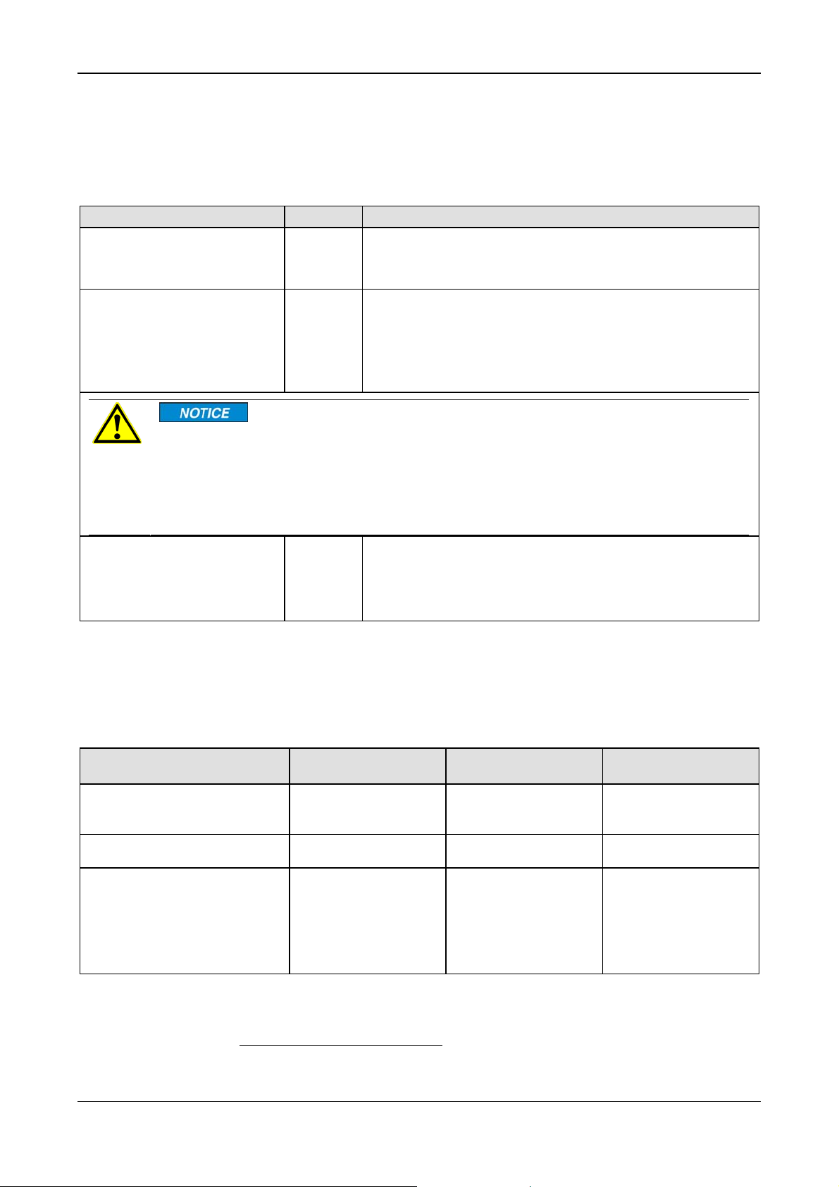
2.2 Intended Use
The PC Cards cifX described in this user manual are PC cards for the RealTime Ethernet or fieldbus communication. Depending from the loaded
firmware, the Real-Time Ethernet or fieldbus systems listed in the following
table can be realized using the respective PC Card cifX.
PC Cards cifX Real-Time Ethernet System PC Cards cifX Fieldbus System
CIFX 50-RE,
CIFX 50E-RE,
CIFX 70E-RE,
CIFX 100EHRE\CUBE
EtherCAT Master,
EtherCAT Slave
EtherNet/IP Scanner (Master),
EtherNet/IP Scanner (Slave)
Open-Modbus/TCP
Powerlink Controlled Node/Slave
PROFINET IO-RT Controller (Master),
PROFINET IO-RT Device (Slave)
sercos Master,
sercos Slave
VARAN Client (Slave)
Table 7: PC Cards cifX and the Real-Time Ethernet or Fieldbus Systems realized thereby
CIFX 50-DP
CIFX 50E-DP,
CIFX 70E-DP
CIFX 50-2DP
CIFX 50-CO
CIFX 50E-CO,
CIFX 70E-CO
CIFX 50-DN
CIFX 50E-DN,
CIFX 70E-DN
CIFX 50-2ASM AS-Interface Master
CIFX 50-CC
CIFX 50E-CC
CIFX 50-CP
CIFX 50E-CP
PROFIBUS DP Master,
PROFIBUS DP Slave,
PROFIBUS MPI Device
PROFIBUS DP Master,
PROFIBUS DP Slave
CANopen Master,
CANopen Slave
DeviceNet Master,
DeviceNet Slave
CC-Link Slave
CompoNet Slave
2.3 Personnel Qualification
The PC Card cifX must only be installed, configured and removed by
qualified personnel. Job-specific technical skills for people professionally
working with electricity must be present concerning the following topics:
• Safety and health at work
• Mounting and connecting of electrical equipment
• Measurement and Analysis of electrical functions and systems
• Evaluation of the safety of electrical systems and equipment
• Installing and Configuring IT systems
PC Cards cifX PCI, PCIe, Low Profile PCIe | Installation, Operation and Hardware Description
DOC120204UM36EN | Revision 36 | English | 2012-10 | Released | Public © Hilscher, 2008-2012
Page 19

Safety 19/145
2.4 Safety Instructions to avoid Personal Injury
To ensure your own personal safety and to avoid personal injury, you
necessarily must read, understand and follow the following safety
instructions and safety messages in this manual about danger causing
personal injury, before you install and operate your PC card cifX.
2.4.1 Electrical Shock Hazard
The danger of a lethal electrical shock caused by parts with more than 50V
may occur if you open the PC cabinet to install the PC Card cifX.
• HAZARDOUS VOLTAGE is present inside of the PC or of the connecting device, into which the PC Card cifX is integrated. Strictly obey to all
safety rules provided by the device’s manufacturer in the documentation!
• First disconnect the power plug of the PC or of the connecting device,
before you open the cabinet.
• Make sure, that the power supply is off at the PC or at the connecting
device.
• Open the PC cabinet and install or remove the PC Card cifX only after
disconnecting power.
An electrical shock is the result of a current flowing through the human
body. The resulting effect depends on the intensity and duration of the
current and on its path through the body. Currents in the range of
approximately ½ mA can cause effects in persons with good health, and
indirectly cause injuries resulting from startle responses. Higher currents
can cause more direct effects, such as burns, muscle spasms, or
ventricular fibrillation.
In dry conditions permanent voltages up to approximately 42.4 V peak or
60 V are not considered as dangerous if the contact area is equivalent to
the size of a human hand.
Reference Safety [S2]
PC Cards cifX PCI, PCIe, Low Profile PCIe | Installation, Operation and Hardware Description
DOC120204UM36EN | Revision 36 | English | 2012-10 | Released | Public © Hilscher, 2008-2012
Page 20

Safety 20/145
2.5 Safety Instructions to avoid Property Damage
To avoid property damage respectively device destruction to the PC card
cifX and to your system, you necessarily must read, understand and follow
the following safety instructions and safety messages in this manual about
danger causing property damage, before you install and operate your PC
card.
2.5.1 Device Destruction by exceeding allowed Supply Voltage
To avoid device destruction due to high supply voltage to your PC Card
cifX, you must observe the following instructions. These instructions apply
to all PC Cards cifX described in this manual.
The PC Card cifX may only be operated with the specified supply voltage.
Make sure that the limits of the allowed range for the supply voltage are not
exceeded. A supply voltage above the upper limit can cause severe
damage to the PC Card cifX! A supply voltage below the lower limit can
cause malfunction in the PC Card cifX. The allowed range for the supply
voltage is defined by the tolerances specified in this manual.
For the PC cards listed hereafter adhere specifically: The PC Card cifX
• CIFX 50-RE
• CIFX 50-DP, CIFX 50-2DP, CIFX 50-CO, CIFX 50-DN, CIFX 50-2ASM,
CIFX 50-CC, CIFX 50-CP
• CIFX 50E-RE,
• CIFX 50E-DP, CIFX 50E-CO, CIFX 50E-DN, CIFX 50E-2ASM,
CIFX 50E-CC, CIFX 50E-CP
• CIFX 70E-RE, CIFX 100EH-RE\CUBE
• CIFX 70E-DP, CIFX 70E-CO, CIFX 70E-DN
may not be powered by a 5V supply voltage! The PC Card cifX may only be
powered by a 3.3 V ±5 % supply voltage.
The data on the mandatory supply voltage for the PC Cards cifX described
in this manual you find in the
page
27. There the required and permitted supply voltage is provided by
Supply Voltage and Signaling Voltage on
device type inclusively the permitted tolerance range.
PC Cards cifX PCI, PCIe, Low Profile PCIe | Installation, Operation and Hardware Description
DOC120204UM36EN | Revision 36 | English | 2012-10 | Released | Public © Hilscher, 2008-2012
Page 21

Safety 21/145
2.5.2 Device Destruction by exceeding allowed Signaling Voltage
To avoid device destruction due to high signal voltage to your PC Card cifX,
you must observe the following instructions. These instructions apply to all
PC Cards cifX described in this manual.
• All I/O signal pins at the PC Card cifX tolerate only the specified
signaling voltage!
• Operating of your PC Card cifX with a signaling voltage other than the
specified signaling voltage may lead to severe damage to the PC Card
cifX!
The data on the mandatory signaling voltage for the PC Cards cifX
described in this manual you find in the section
Signaling Voltage on page
27. There the required and permitted signaling
Supply Voltage and
voltage is provided by device type.
2.5.3 Electrostatically sensitive Devices
This equipment is sensitive to electrostatic discharge, which cause internal
damage and affect normal operation. Therefore adhere to the necessary
safety precautions for components that are vulnerable with electrostatic
discharge if you install or replace your device. Follow the guidelines listed
hereafter when you handle this equipment:
• Touch a grounded object to discharge potential static.
• Wear an approved grounding wriststrap.
• Do not touch connectors or pins on the PC Card cifX.
• Do not touch circuit components inside the equipment.
• If available, use a static-safe workstation.
• When not in use, store the equipment in appropriate static-safe
packaging.
Reference Safety [S3]
PC Cards cifX PCI, PCIe, Low Profile PCIe | Installation, Operation and Hardware Description
DOC120204UM36EN | Revision 36 | English | 2012-10 | Released | Public © Hilscher, 2008-2012
Page 22
Safety 22/145
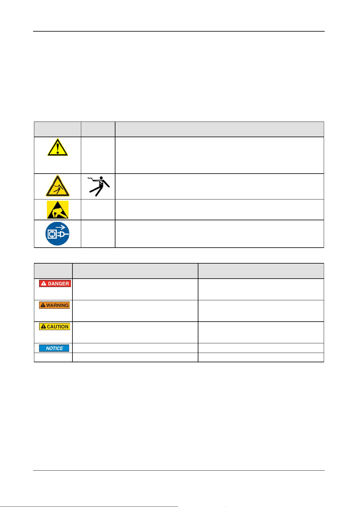
2.6 Labeling of Safety Messages
• The Section Safety Messages at the beginning of a chapter are
pinpointed particularly. They are highlighted with a specific safety
symbol and a signal word according to the degree of endangerment.
Inside the safety message the danger is exactly named.
• The Integrated Safety Messages within an instruction description are
highlighted with a signal word according to the degree of endangerment
and possibly by a principle symbol. Inside the safety message the
danger is exactly named.
Safety
Symbol
USA Sort of Warning or Principle
Warning of Personal Injury and Propert y Damage Message
USA: Warning of Personal Injury
As in the scope of the ANSI Z535 Standard (for USA) instructions to a property damage
message may not contain a warning triangle, this property damage messages are listed
separately for the USA.
Warning of Lethal Electrical Shock
Signal
Word
Note
Warning of Damages by Electrostatic Discharge
Principle: Disconnect the Power Plug
Meaning Meaning (USA)
Indicates a direct hazard with high risk, which
will have as consequence death or grievous
bodily harm if it isn't avoided.
Indicates a possible hazard with medium risk,
which will have as consequence death or
(grievous) bodily harm if it isn't avoided.
Indicates a minor hazard with medium risk,
which could have as consequence simple
battery if it isn't avoided.
Indicates a Property Damage Message. Indicates a Property Damage Message.
Indicates an important note in the manual. Indicates an Important Note in the Manual.
Table 8: Safety Symbols and Sort of Warning or Principle
Indicates a Hazardous Situation Which if not
Avoided, will Result in Death or Serious Injury.
Indicates a Hazardous Situation Which if not
Avoided, could Result in Death or Serious
Injury.
Indicates a Hazardous Situation Which if not
Avoided, may Result in Minor or Moderate
Injury.
Table 9: Signal Words
In this document all Safety Instructions and Safety Messages are designed
according both to the international used safety conventions as well as to
the ANSI Z535 standard, refer to reference safety [S1].
2.7 References Safety
ANSI Z535.6-2006 American National Standard for Product Safety Information in
[S1]
Product Manuals, Instructions, and Other Collateral Materials
IEC 60950-1, Information technology equipment - Safety - Part 1: General
[S2]
requirements, (IEC 60950-1:2005, modified); German Edition EN 60950-1:2006
[S3] EN 61340-5-1 and EN 61340-5-2 as well as IEC 61340-5-1 and IEC 61340-5-2
PC Cards cifX PCI, PCIe, Low Profile PCIe | Installation, Operation and Hardware Description
DOC120204UM36EN | Revision 36 | English | 2012-10 | Released | Public © Hilscher, 2008-2012
Page 23

Descriptions and Requirements 23/145
3 Descriptions and Requirements
3.1 Description
The PC Cards cifX are communication interfaces of the cifX product family
of Hilscher on the basis of the communication controller netX 100 for the
Real-Time Ethernet or fieldbus communication. Depending of the loaded
firmware, the protocol specific
the corresponding Real-Time Ethernet or fieldbus system.
The used Real-Time Ethernet systems are: The used fieldbus systems
PC Card cifX proceeds the communication of
are:
EtherCAT Master
EtherCAT Slave
EtherNet/IP Scanner (Master)
EtherNet/IP Adapter (Slave)
Open-Modbus/TCP
Powerlink-Controlled-Node/Slave
PROFINET IO-RT Controller (Master)
PROFINET IO-RT Device (Slave)
sercos Master
sercos Slave
VARAN Client (Slave)
PROFIBUS DP Master
PROFIBUS DP Slave
PROFIBUS MPI Device
CANopen Master
CANopen Slave
DeviceNet Master
DeviceNet Slave
AS-Interface Master
CC-Link Slave
CompoNet Slave
The PC Card cifX handles the complete data exchange between the
connected Ethernet or fieldbus devices and the PC. The data exchange is
proceeded via dual-port memory.
PC Cards cifX PCI, PCIe, Low Profile PCIe | Installation, Operation and Hardware Description
DOC120204UM36EN | Revision 36 | English | 2012-10 | Released | Public © Hilscher, 2008-2012
Page 24

Descriptions and Requirements 24/145
3.1.1 Devices described in this Manual
PC Card cifX Description
CIFX 50-RE
CIFX 50E-RE PC Card cifX PCI Express for Real-Time Ethernet Master or Slave
CIFX 50-DP
CIFX 50-2DP
CIFX 50E-DP PC Card cifX PCI Express PROFIBUS DP Master or Slave and PROFIBUS MPI Device
CIFX 50-CO PC Card cifX PCI CANopen Master or Slave
CIFX 50E-CO PC Card cifX PCI Express CANopen Master or Slave
CIFX 50-DN PC Card cifX PCI DeviceNet Master or Slave
CIFX 50E-DN PC Card cifX PCI Express DeviceNet Master or Slave
CIFX 50-2ASM PC Card cifX PCI
CIFX 50E-2ASM PC Card cifX PCI Express
CIFX 50-CC
CIFX 50E-CC
CIFX 50-CP
CIFX 50E-CP
CIFX 70E-RE
CIFX 70E-DP
CIFX 70E-CO
CIFX 70E-DN
CIFX 100EHRE\CUBE
PC Card cifX PCI for Real-Time Ethernet Master or Slave
PC Card cifX PCI PROFIBUS DP Master or Slave and PROFIBUS MPI Device
PC Card cifX PCI 2 channel PROFIBUS DP Master and PROFIBUS MPI Device
2 channel AS-Interface Master
2 channel AS-Interface Master
PC Card cifX PCI CC-Link Slave
PC Card cifX PCI Express CC-Link Slave
PC Card cifX PCI CompoNet Slave
PC Card cifX PCI Express CompoNet Slave
PC Card cifX Low Profile PCI Express Real-Time-Ethernet Master or Slave
(Low Profile PCIe with RTE)
PC Card cifX Low Profile PCI Express PROFIBUS DP Master or Slave
und PROFIBUS MPI Device (Low Profile PCIe with PROFIBUS)
PC Card cifX Low Profile PCI Express CANopen Master or Slave
(Low Profile PCIe with CANopen)
PC Card cifX Low Profile PCI Express DeviceNet Master or Slave
(Low Profile PCIe with DeviceNet)
PC Card cifX PCI Express for Real-Time Ethernet Master or Slave,
(low-profile card) exclusively for the installing in KEBA KeControl industry PCs series CP 3XX
(Cube).
Table 10: PC Cards cifX
3.1.2 The Function „Slot Number (Card ID)“
Device revisions equipped with a Rotary Switch Slot Number (Card ID)
are listed separately in section
Table 2.
The Slot Number (Card ID) must be set at the PC Card cifX using the
Rotary Switch Slot Number (Card ID). The Slot Number (Card ID) will
serve to distinguish PC Cards cifX from each other clearly, especially if
several PC Cards cifX are installed into the very same PC. The application
program requests the Slot Number (Card ID) from the PC card cifX via the
cifX Device Driver.
For further information refer to section
(Card ID) on page
PC Cards cifX PCI, PCIe, Low Profile PCIe | Installation, Operation and Hardware Description
DOC120204UM36EN | Revision 36 | English | 2012-10 | Released | Public © Hilscher, 2008-2012
91.
Hardware: PC Cards cifX on page 14 in
Rotary Switch for Slot Number
Page 25
Descriptions and Requirements 25/145
Requirements
For the application program is able to identify a PC Card cifX via its Slot
Number (Card ID) explicitly and to distinguish it from other PC Cards cifX
in the PC, for device revisions equipped with a Rotary Switch for Slot
Number (Card ID) the required versions of the firmware, the driver, the
bootloader and the SYCON.net setup must be used:
PC Card cifX
CIFX 50-RE,
CIFX 50E-RE,
CIFX 70E-RE
,
CIFX 100EHRE\CUBE
CIFX 50-DP,
CIFX 50E-DP,
CIFX 70E-DP
CIFX 50E-CO,
CIFX 70E-CO
CIFX 50E-DN,
CIFX 70E-DN
CIFX 50-2ASM,
CIFX 50E-2ASM
CIFX 50-CC,
CIFX 50E-CC
CIFX 50-CP,
CIFX 50E-CP
From Hardware
Firmware File Protocol
Revision
3,
4,
1
5,
4,
4,
2,
,
1
5
1
5
1
5
1
2
2
2
3
3
CIFXECM.NXF EtherCAT Master 2.4.3.x
CIFXECS.NXF EtherCAT Slave 2.5.5.x
CIFXEIM.NXF EtherNet/IP Scanner 2.2.1.x
CIFXEIS.NXF EtherNet/IP Adapter 2.3.29.x
CIFXOMB.NXF Open-Modbus/TCP 2.3.3.0
CIFXPLS.NXF POWERLIN K Controlled Node 2.1.19.x
CIFXPNM.NXF PROFINET IO Controller 2.3.x.x
CIFXPNS.NXF PROFINET IO Device 3.3.6.x (V3)
CIFXS3M.NXF sercos Master 2.0.9.0
CIFXS3S.NXF sercos Slave 3.0.8.0
CIFXVRS.NXF VARAN Client 1.0.x.x
CIFXDPM.NXF PROFIBUS DP Master 2.3.x.x
CIFXDPS.NXF PROFIBUS DP Slave 2.3.x.x
CIFXMPI.NXF PROFIBUS MPI Device 2.2.5.0
CIFXCOM.NXF CANopen Master 2.3.x.x CIFX 50-CO,
CIFXCOS.NXF CANopen Slave 2.3.x.x
CIFXDNM.NXF DeviceNet Master 2.2.x.x CIFX 50-DN,
CIFXDNS.NXF DeviceNet Slave 2.2.x.x
CIFX2ASM.NXF AS-Interface Master 2.1.x.x
CIFXCPS.NXF CC-Link Slave 2.4.x.x
CIFXCPS.NXF CompoNet Slave 1.0.4.0
Table 11: Firmware Versions for the Function Slot Number (Card ID)
From Firmware
Version
Driver and Software Version or higher
cifX Device Driver
Bootloader (is included in the cifX Device Driver Setup)
SYCON.net
cifX Device Driver Setup.exe
SYCONnet netX setup.exe
0.95x
V1.3.x.x
V1.201.x.x
Table 12: Versions Driver, Bootloader and SYCON.net for Function Slot Number (Card ID)
• The cifX Device Driver from version 0.950 on identifies PC Cards cifX
alternatively via its Slot Number (Card ID).
• The cifX Device Driver up to version 0.94x identifies PC Cards cifX via
its device and serial number. For the device exchange service
respectively a manual intervention is required.
PC Cards cifX PCI, PCIe, Low Profile PCIe | Installation, Operation and Hardware Description
DOC120204UM36EN | Revision 36 | English | 2012-10 | Released | Public © Hilscher, 2008-2012
Page 26
Descriptions and Requirements 26/145
3.1.3 The Function „IO-DMA Mode“
Device revisions which provide IO-DMA Mode are listed separately in
PC Card cifX
CIFX 50-RE
CIFX 50E-RE,
CIFX 70E-RE
,
CIFX 100EHRE\CUBE
CIFX 50-DP,
CIFX 50E-DP,
CIFX 70E-DP
CIFX 50E-CO,
CIFX 70E-CO
CIFX 50E-DN,
CIFX 70E-DN
CIFX 50-2ASM,
CIFX 50E-2ASM
CIFX 50-CC,
CIFX 50E-CC
CIFX 50-CP,
CIFX 50E-CP
section
Note: The functions Slot Number (Card ID) and IO-DMA Mode are in
technical view independently from each other.
The IO-DMA Mode is activated via the device driver cifX Device Driver.
For further information refer to the user manual Software Installation for
the PC Cards cifX in section Activating IO-DMA Mode in the cifX Device
Driver Setup.
Requirements
For device revisions providing the IO-DMA Mode the required versions of
the firmware, the driver and the SYCON.net setup must be used:
From Hardware
Revision
1,
4,
1
,
1
1,
4,
1
1,
4,
1
1
4,
1
2,
4
1,
3
1,
3
Table 13: Firmware Versions for the IO-DMA Mode
Hardware: PC Cards cifX on page 14 in Table 2.
Firmware File Protocol
CIFXECM.NXF EtherCAT Master 2.4.6.0
CIFXECS.NXF EtherCAT Slave 2.5.5.0
CIFXEIM.NXF EtherNet/IP Scanner 2.2.x.x
CIFXEIS.NXF EtherNet/IP Adapter 2.3.x.x
CIFXOMB.NXF Open-Modbus/TCP 2.4.x.x
CIFXPLS.NXF POWERLINK Controlled Node 2.1.24.0
CIFXPNM.NXF PROFINET IO Controller 2.3.x.x
CIFXPNS.NXF PROFINET IO Device 3.4.x.x (V3)
CIFXS3M.NXF sercos Master 2.0.15.0
CIFXS3S.NXF sercos Slave 3.0.15.0
CIFXVRS.NXF VARAN Client 1.0.x.x
CIFXDPM.NXF PROFIBUS DP Master 2.3.x.x
CIFXDPS.NXF PROFIBUS DP Slave 2.3.x.x
CIFXMPI.NXF PROFIBUS MPI Device not supported
CIFX2DPM.NXF PROFI BUS DP Master, 2 Chan nels 2.3.x.x CIFX 50-2DP 1
CIFX2DPS.NXF PROFIBUS DP Slave, 2 Channels 2.4.4.1
CIFXCOM.NXF CANopen Master 2.3.x.x CIFX 50-CO,
CIFXCOS.NXF CANopen Slave 2.3.x.x
CIFXDNM.NXF DeviceNet Master 2.2.x.x CIFX 50-DN,
CIFXDNS.NXF DeviceNet Slave 2.2.x.x
CIFX2ASM.NXF AS-Interface Master 2.1.x.x
CIFXCCS.NXF CC-Link Slave 2.4.x.x
CIFXCPS.NXF CompoNet Slave 1.0.4.0
From Firmware
Version
Driver and Software Version or higher
cifX Device Driver
SYCON.net
cifX Device Driver Setup.exe
SYCONnet netX setup.exe
0.95x
V1.201.x.x
Table 14: Versions Driver and SYCON.net for the IO-DMA Mode
PC Cards cifX PCI, PCIe, Low Profile PCIe | Installation, Operation and Hardware Description
DOC120204UM36EN | Revision 36 | English | 2012-10 | Released | Public © Hilscher, 2008-2012
Page 27
Descriptions and Requirements 27/145
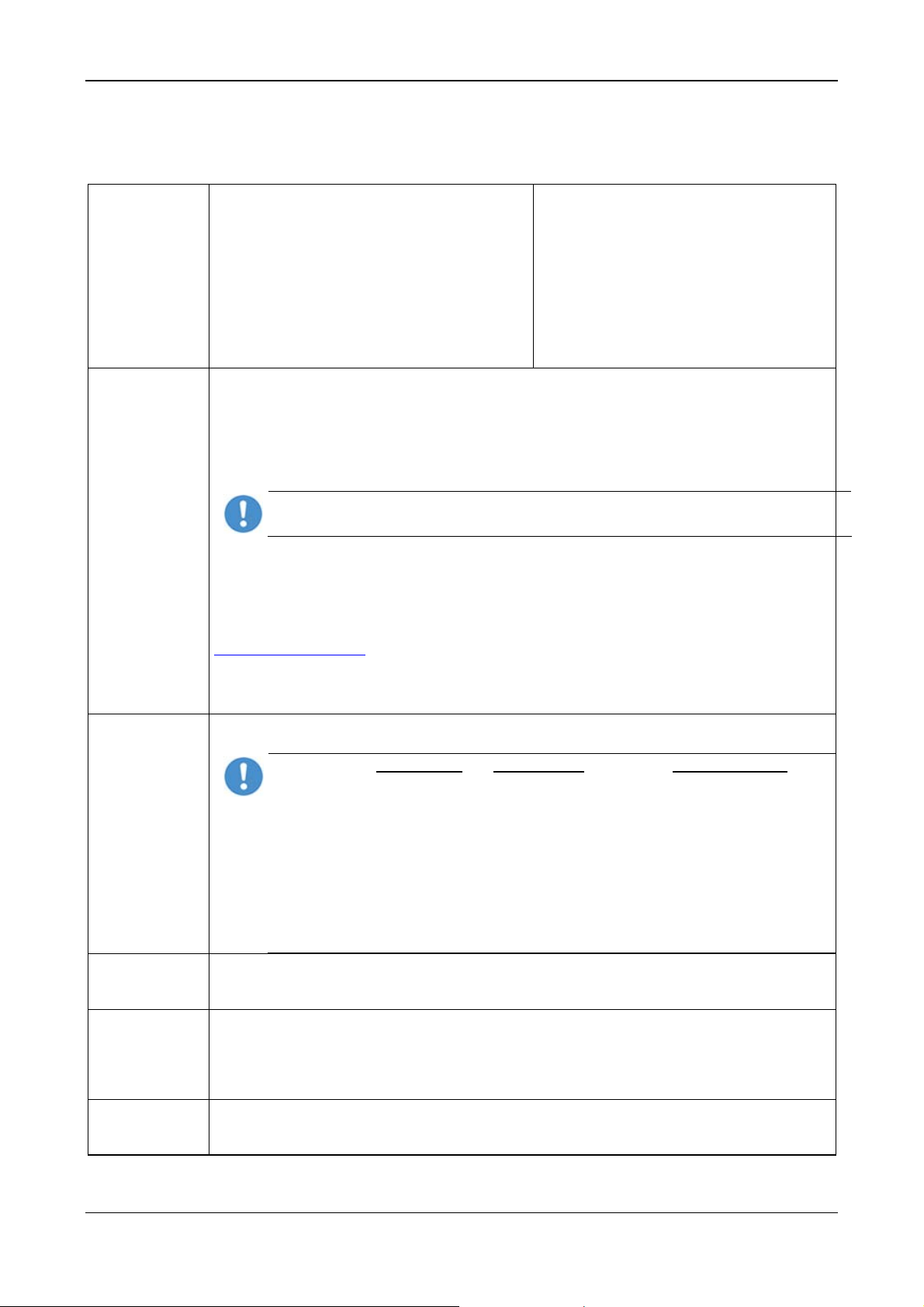
3.2 System Requirements
3.2.1 Slot for the PC Cards cifX PCI, PCIe and Low Profile PCIe
PC with slot (3.3 V) for PC Cards cifX PCI, PCI Express and Low Profile PCI
Express:
PC Cards cifX Bus [Pins] Slot
CIFX 50-RE
CIFX 50-DP
CIFX 50-2DP
CIFX 50-CO
CIFX 50E-RE
CIFX 50E-DP
CIFX 50E-CO
CIFX 50E-DN
CIFX 50E-2ASM
CIFX 50E-CC
CIFX 50E-CP
CIFX 100EH-RE\CUBE 64
CIFX 50-DN
CIFX 50-2ASM
CIFX 50-CC
CIFX 50-CP
CIFX 70E-RE,
CIFX 70E-DP,
CIFX 70E-CO,
CIFX 70E-DN
Device Destruction!
The PC card CIFX 100EH-RE\CUBE may not be installed in standard PCs.
The pin assignment of the PCI Express bus does not meet the standard [bus spec 3]. By consequence
malfunction can occur at the PCI express bus.
Install the PC card CIFX 100EH-RE\CUBE exclusively in KEBA KeControl industry PCs series CP 3XX
(Cube).
Table 15: Slot for the PC Cards cifX PCI, PCIe and Low Profile PCIe
124
36
PCI slot (3.3 V)
PCI Express x1 slot (3.3 V),
x13 = One Lane [bus spec 3]
PCI Express x4 slot (3.3 V) ,
x43 = Four Lane
In the PCI Express x4 slot only lane 0 is used. For further details
refer to section
RE\CUBE on page
Pin Assignment for PCI Express Bus CIFX 100EH-
96.
3.2.2 Supply Voltage and Signaling Voltage
For the supply and signaling voltage for the PC Cards cifX PCI, PCIe and
Low Profile PCIe the following data are valid:
PC Cards cifX Supply Voltage
CIFX 50-RE
CIFX 50-DP
CIFX 50-CO
CIFX 50-2DP, CIFX 50-2ASM +3,3 V ±5 %/ Typ. 700 mA 5 V or 3,3 V
CIFX 50E-RE
CIFX 50E-DP
CIFX 50E-CO
CIFX 50E-DN
CIFX 50E-2ASM
CIFX 50E-CC
CIFX 100EH-RE\CUBE
CIFX 50-DN
CIFX 50-CC
CIFX 50-CP
CIFX 50E-CP
CIFX 70E-RE,
CIFX 70E-DP,
CIFX 70E-CO,
CIFX 70E-DN
+3,3 V ±5 %/ Typ. 650 mA 5 V or 3,3 V
+3,3 V ±5 %/ Typ. 800 mA PCIe-compatible
Table 16: Supply and Signaling Voltage PC Cards cifX PCI, PCIe Low Profile PCIe
3
The terms "x1" or "x4“ refer to the convention of the PCI Express specifications
[bus spec 3] to the number of lanes in the slot.
Signaling Voltage
Host Interface
Host Interface
(PCI slot)
PCI
PCI
PCI-Express
PC Cards cifX PCI, PCIe, Low Profile PCIe | Installation, Operation and Hardware Description
DOC120204UM36EN | Revision 36 | English | 2012-10 | Released | Public © Hilscher, 2008-2012
Page 28

Descriptions and Requirements 28/145
The data in the Table 10: PC Cards cifX on page 24 have the following
meaning:
Supply Voltage
The required and permissible supply voltage at the PC Cards cifX PCI,
PCIe and Low Profile PCIe
Signaling Voltage Host Interface
The required or tolerated signaling voltage at the I/O signal pins at the PCI
bus of the PC Cards cifX PCI or at the PCI express bus of the PC Cards
cifX PCIe and Low Profile PCIe.
Host Interface (PCI slot) Type of the host interface
3.2.3 System Requirements SYCON.net
• PC with 1 GHz processor or higher
• Windows
Windows
• Administration rights
• Internet Explorer 5.5 or higher
®
XP SP3, Windows® Vista (32 bit) SP2, Windows® 7 (32 bit) or
®
7 (64 bit)
• Free disk space: min. 400 MByte
• DVD ROM drive
• RAM: min. 512 MByte, recommended 1024 MByte
• Graphic resolution: min. 1024 x 768 pixel
• Keyboard and Mouse
• USB (optional)
Note: If the project file is saved and opened again or if it is used on
another PC, the system requirements must match. Particularly the DTM
must be installed on the used PC.
3.2.4 System Requirements for netX Configuration Tool
The system requirements necessary for the application of the netX
Configuration Tool are these:
• PC with 586-, Pentium
• Operating system: Windows
Windows
®
7 (32 bit) or Windows® 7 (64 bit)
®
processor or higher
®
XP SP3, Windows® Vista (32 bit) SP2,
• Free space on hard disk: 50 MByte
• DVD drive
• RAM: min. 256 MByte
• Graphics resolution: min 1024 x 768 pixels
• Keyboard and mouse for input and operation
PC Cards cifX PCI, PCIe, Low Profile PCIe | Installation, Operation and Hardware Description
DOC120204UM36EN | Revision 36 | English | 2012-10 | Released | Public © Hilscher, 2008-2012
Page 29
Descriptions and Requirements 29/145
3.3 Requirements for Operation of the PC Card cifX
For PC Cards cifX to operate properly, the following described
requirements must be fulfilled.
Protocols
EtherCAT Slave,
EtherCAT Master,
EtherNet/IP Adapter (Slave),
EtherNet/IP Scanner (Master),
Open-Modbus/TCP,
Powerlink-Controlled-Node/Slave,
PROFINET IO Device (Slave),
PROFINET IO Controller (Master)
sercos Slave,
sercos Master,
VARAN Client (Slave)
Software
Installation
1. Driver for the Host Interface
Host Interfaces: PCI and PCI Express
• The device driver cifX Device Driver must be installed (from V1.0.x.x).
If you install the device into a PC, in general Windows
case the cifX Device Driver must be installed to communicate to the device and to exchange data
via the dual-port memory,.
Important! Upgrade older versions of the cifX Device Driver necessarily on the current
version indicated in section Reference on Driver and Software on page 14.
OR
®
• If Windows
is not available as operating system, an own driver must be developed using the cifX
Driver Toolkit and this driver must be installed.
• For the operating systems Linux, Windows® CE, VxWorks, QNX and IntervalZero RTX ™ you can
buy Device Driver at the company Hilscher Gesellschaft für Systemautomation mbH
http://www.hilscher.com/.
2. The configuration software SYCON.net or alternatively the simple Slave configuration tool netX
Configuration Tool must be installed or another application program by which the PC Card cifX
(Slave) can be parameterized.
How to use the
Software
On how to use the software for the configuration, the firmware download and for the diagnosis, note
the following notice:
Important! The USB interface, the serial interface as well as the cifX Device Driver may
only be used exclusively by one software, that is
- the SYCON.net configuration software (with integrated ODMV3) or
- the netX Configuration Tool or
- the cifX Test Application or
- the cifX Driver Setup Utility or
- the application program.
Never use the listed software simultaneously, otherwise this will result in communication
problems with the device.
If the SYCON.net configuration software was used on the PC, then stop the ODMV3
service before you use one of the other software listed above. Therefore, select Service
Firmware
Download
> Stop from the context menu of the ODMV3 system tray icon.
3. Using the configuration software SYCON.net or for the Slave alternatively the Slave configur ation
tool netX Configuration Tool, the user must select and download the firmware to the PC Card
cifX.
Parameter
Setting
4. The PC Card cifX must be parameterized using one of the following options:
• Configuration Software SYCON.net
• alternatively Slave configuration tool netX Configuration Tool (only Slave)
• Application program (programming required)
Communication 5. For the communication of a PC card cifX (Slave) a Master device for the respective
communication system is required. For the communication of a PC card cifX (Master) a Slave
device for the respective communication system is required.
Table 17: Requirements to operate PC Cards cifX properly
PROFIBUS DP Slave,
PROFIBUS DP Master,
PROFIBUS MPI Device,
CANopen Slave,
CANopen Master,
DeviceNet Slave,
DeviceNet Master,
AS-Interface Master;
CC-Link Slave,
CompoNet Slave
®
will be available as operating system. In this
PC Cards cifX PCI, PCIe, Low Profile PCIe | Installation, Operation and Hardware Description
DOC120204UM36EN | Revision 36 | English | 2012-10 | Released | Public © Hilscher, 2008-2012
Page 30
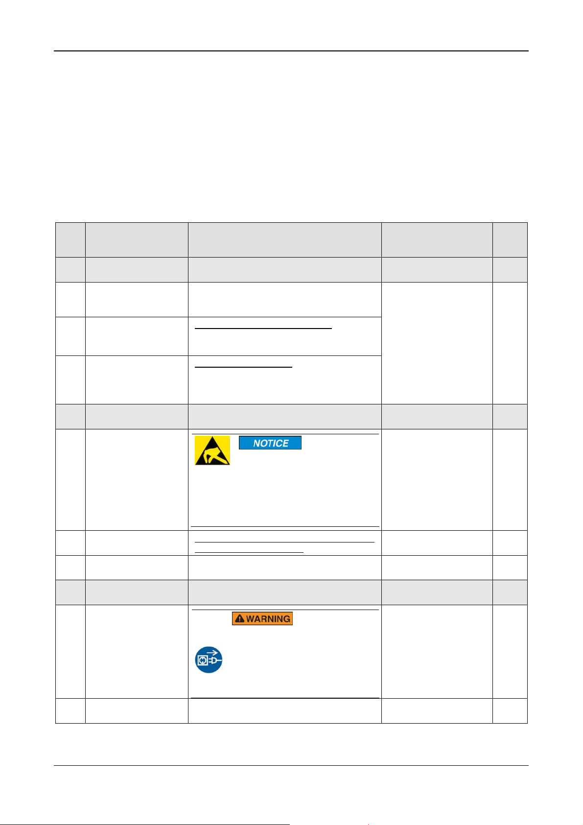
Getting Started 30/145
4 Getting Started
4.1 Installation and Configuration PC Card cifX
The following table describes the steps for the software and hardware
installation and for the configuration of a PC Card cifX (Master and Slave)
Real-Time Ethernet and fieldbus as it is typical for many cases. The Slave
device can be configured using the corresponding Slave DTM in the
configuration software SYCON.net. Alternatively, you can also use the
simple Slave configuration tool netX Configuration Tool. The Master
device can be configured using the corresponding Master DTM in the
configuration software SYCON.net.
# Step Description
1
1.1
1.2 Installi ng SYCON.net For PC Cards cifX Master or Slave:
1.3
2
2.1
2.2
2.2
3 Hardware Settings Installing cifX. Take required safety
3.1
3.2 Open cabinet
Installing Driver and
Software
Installing
cifX Device Driver
Installing
Configuration Tool
Preparing Hardware
Installation
Take precautions on
Electrostatically
sensitive Devices
Glue sticker on the
front plate.
Set the Slot Number
(Card ID)
Take safety
precautions
netX
Enter the Communication Solutions DVD in
the PC and follow to the instructions of the
installation wizard, to install the driver.
Run the SYCON.net-Setup and follow to the
instructions of the installation wizard.
For PC Cards cifX Slave:
Start the netX Configuration Tool setup
program to install the netX Configuration
Tool.
Electrostatically sensitive
Devices
Make sure, that the PC card cifX
is grounded via the endplate and
the PC and make sure, that you
are discharged when you install/
uninstall the PC Card cifX.
For CIFX 50-RE, CIFX 50E-RE, CIFX 70E-RE
and CIFX 100EH-RE\CUBE
Value 0 or a value from 1 to 9 Rotary Switch for Slot
precautions.
Lethal Electrical Shock caused
by parts with more than 50V!
Disconnect the power plug of the
PC or of the connecting device.
Make sure, that the power supply is
off at the PC or at the connecting
device.
Now open the cabinet of the PC or of the
connecting device.
For detailed
information see
manual / section
Refer to User Manual
Software Installation for
the PC Cards cifX
Electrostatically sensitive
Devices
Fix Front Plate Sticker 59
Number (Card ID)
Hardware Installation
and Uninstalling
Electrical Shock Hazard
Installing PC Card cifX PCI,
PCIe, Low Profile PCIe
Page
21
91
57
19
62
PC Cards cifX PCI, PCIe, Low Profile PCIe | Installation, Operation and Hardware Description
DOC120204UM36EN | Revision 36 | English | 2012-10 | Released | Public © Hilscher, 2008-2012
Page 31

Getting Started 31/145
# Step Description
3.3 Installing cifX Plug in and mount the PC card cifX.
Notice for CIFX 100EH-RE\CUBE:
Device Destruction!
Install the PC card CIFX 100EHRE\CUBE exclusively in KEBA
KeControl industry PCs series CP
3XX (Cube). Otherwise yy
consequence malfunction can
occur at the PCI express bus.
3.4 Close cabinet
Close the cabinet of the PC or connecting
device.
3.5
Plug the connecting
cable to the Master or
Slave
Note for all PC Cards cifX Real-Time
Ethernet:
Important! When using Ethernet
TCP/UDP/IP, EtherNet/IP or
Modbus TCP at 10 MBit/s use only
switches or 10/100 MBit/s dualspeed hubs and ensure that the
network operates at 100 MBit/s and
in full-duplex mode.
Note! The RJ45 socket is only for
use in LAN, not for telecommunication circuits.
Note for PC Cards cifX PROFINET IO
Controller:
Important for Hardware Wiring!
Connect only ports with each other,
which have different cross-over settings. Otherwise a connection between the devices can not be established. If the port settings of the PC
card cifX PROFINET IO controller
are not set to AUTO, then Port0 is
switched uncrossed and Port1
crossed.
Plug in the connecting cable from the PC card
cifX to the PC card Master or Slave.
3.6
Connect the PC to the
power / switch on.
4 Hardware Settings
4.1
Set Slot Number
(Card ID)
Connect the PC or the connecting device to
the power supply and switch it on.
Hardware Settings in the Driver Setup
Set in the cifX Device Driver Setup the Slot
Number (Card ID) which has been set at the
PC card cifX (hardware).
4.2
IO-DMA Mode in the
cifX Device Driver
Activate the IO-DMA Mode in the cifX Device
Driver Setup.
Setup
5
Notice on how to use
Use only one Software.
the Software
5.1
For the configuration,
the firmware download
and for the diagnosis,
note:
Important! To avoid communication
problems with the device, use the
USB interface
, the serial interface as
well as the cifX Device Driver
exclusively with one software that is
SYCON.net or netX Configuration
Tool.
For detailed
Page
information see
manual / section
Failure in 10 MBit/s Half
65
Duplex Mode and
Workaround
Ethernet Interface
86
See corresponding user
manual
Refer to User Manual
Software Installation for
the PC Cards cifX
Requirements for
29
Operation of the PC
Card cifX
PC Cards cifX PCI, PCIe, Low Profile PCIe | Installation, Operation and Hardware Description
DOC120204UM36EN | Revision 36 | English | 2012-10 | Released | Public © Hilscher, 2008-2012
Page 32

Getting Started 32/145
# Step Description
6
Configuring Slave
using SYCON.net
Download Firmware and Configuration
Use the corresponding Slave DTM in the
configuration software SYCON.net.
6.1 F irmware Download
- Start configuration software SYCON.net,
- Create new project /Open existing project,
- Insert Slave into configuration,
- Select driver and assign device.
- Select and download the firmware.
6.2
Firmware Slave:
Configuration
EtherCAT Slave,
EtherNet/IP Adapter,
Open-Modbus/TCP,
Powerlink-ControlledNode/Slave,
PROFINET IO Device,
sercos Slave,
VARAN Client,
-Configure the PC Card cifX (Slave).
cifX (Slave)
6.3
7
Download
Configuration
OR Configuring
- Download the configuration to the PC card
cifX (Slave)
Download Firmware and Configuration
Slave using netX
Configuration Tool
7.1
Downloading Firmware
and Configuration
(Slave)
If SYCON.net was already used on the PC,
stop the ODMV3 service. Therefore, select
Service > Stop from the context menu of the
ODMV3 system tray icon.
PROFIBUS DP Slave,
PROFIBUS MPI
Device,
CANopen Slave,
DeviceNet Slave,
CompoNet Slave,
CC-Link Slave
For detailed
information see
manual / section
See corresponding user
manual
Device Names in
SYCON.net
Requirements for
Operation of the PC
Card cifX
Page
35
29
8
Configuring Master
using SYCON.net
8.1 F irmware Download
8.2
Firmware Master:
Configuration
cifX (Master)
The ODMV3 system tray icon changes to
ODMV3 Service stopped.
In the netX Configuration Tool:
- select the Firmware protocol,
- Set the PC Card cifX (Slave) parameters.
- Select Apply.
The selected firmware and the configuration
are downloaded to the replacement card cifX.
The configuration is saved to the hard disk of
the PC.
Download Firmware and Configuration
Use the corresponding Master DTM in the
configuration software SYCON.net.
- Start configuration software SYCON.net,
- Create new project /Open existing project,
- Insert Master into configuration,
- Select driver and assign device.
- Select and download the firmware.
EtherCAT Master,
EtherNet/IP Scanner,
PROFINET IO
Controller,
PROFIBUS DP Master,
CANopen Master,
DeviceNet Master,
AS-Interface Master
- Configure the PC Card cifX (Master).
See Operating
Instruction Manual netX
Configuration Tool for
cifX, comX and netJACK
See corresponding user
manual
Device Names in
SYCON.net
Notes for the
Configuration of the
35
33
PC Cards cifX PCI, PCIe, Low Profile PCIe | Installation, Operation and Hardware Description
DOC120204UM36EN | Revision 36 | English | 2012-10 | Released | Public © Hilscher, 2008-2012
Page 33

Getting Started 33/145
# Step Description
8.3
9
9.1 Diagnostic
9.2 I/O Monitor
10
10.1
Download
Configuration
Slave Diagnosis by
SYCON.net
(Slave und Master)
OR Slave Diagnosis
by netX Configuration
Tool (only Slave)
Configuration Steps
cifX (Slave)
- Download the configuration to the PC card
cifX (Master).
Diagnosis, I/O Data
Use the corresponding Slave or Master DTM
in the configuration software SYCON.net.
- Rightclick on the device symbol.
- Select context menu entry Diagnosis,
- then select Diagnosis > General or
Firmware Diagnosis,
- or select Diagnosis > Extended Diagnosis.
- Rightclick on device symbol.
- Select context menu entry Diagnosis,
- then Tools > IO Monitor.
-Check the input or output data.
Diagnosis
If SYCON.net was already used on the PC,
stop the ODMV3 service. Therefore, select
Service > Stop from the context menu of the
ODMV3 system tray icon.
In the netX Configuration Tool:
- In the navigation area click on Diagnostic,
- click in the Diagnostic pane to Start, to
start the communication to the Master device
and to run the diagnosis.
- click on Extended, to run the extended
diagnosis.
Table 18: Steps for the Software and Hardware Installation, the Configuration and for the
Diagnosis of a PC Card cifX (Master and Slave)
For detailed
information see
manual / section
Master Device
See corresponding user
manual
See Operating
Instruction Manual netX
Configuration Tool for
cifX, comX and netJACK
Page
4.2 Note on Exchange Service (Replacement Case)
For the exchange service (replacement case) of a PC card cifX (Master and
Slave) obey to the following note.
Important! For the replacement card cifX with
Rotary Switch Slot
Number (Card ID) set the same Slot Number (Card ID) as at the
previous PC Card cifX (see section
ID) on page
For PC Cards cifX without
91).
Rotary Switch Slot Number (Card ID) in
Rotary Switch for Slot Number (Card
terms of a device exchange service (replacement case) you must
manually download the same firmware and configuration into the
replacement card cifX, as into the preceding cifX.
4.3 Notes for the Configuration of the Master Device
To configure the Master, a device description file is required. Please note
the following notes for the configuration of the Master Device:
System Note
EtherCAT Slave
To configure the Master, an XML file (device description file) is required. The settings in the
used Master must comply with the settings in the Slave to establish communication. Important
parameters are: Vendor ID, Product Code, Serial Number, Revision Number, Output and Input
Data Bytes.
PC Cards cifX PCI, PCIe, Low Profile PCIe | Installation, Operation and Hardware Description
DOC120204UM36EN | Revision 36 | English | 2012-10 | Released | Public © Hilscher, 2008-2012
Page 34

Getting Started 34/145
System Note
EtherNet/IP
Adapter
PowerlinkControlledNode/Slave
PROFINET IO
Device
sercos Slave
PROFIBUS DP
Slave
CANopen Slave
DeviceNet Slave
CC-Link Slave
CompoNet Slave
If the XML file Hilscher cifX RE ECS V2.2.x.xml is use/updated, the firmware with the version
2.2.x must be use/updated.
The loadable firmware supports for the number of cyclic input data and for cyclic output data in
total up to 400 bytes. If more than 200 bytes for input data or for output data should be
exchanged via EtharCAT, then a customer specific XML file is necessary. Additionall y the
following formular applies: (number of input bytes + 3)/4 + (number of output bytes + 3)/4 must
be less or equal to 100.
To configure the Scanner/Master, an EDS file (device description file) is required. The settings
in the used Scanner/Master must comply with the settings in the Adapter/Slave to establish
communication. Important parameters are: Input, Output Data Bytes, Vendor ID, Product Type,
Product Code, Major Rev, Minor Rev, IP Address and Netmask.
To configure the Managing Node/Master, an XDD file (device description file) is required. The
settings in the used Managing Node/Master must comply with the settings in the Controlled
Node/Slave, to establish communication. Important parameters are: Vendor ID, Product Code,
Serial Number, Revision Number, Node ID, Output and Input length.
To configure the Controller, a GSDML file (device description file) is required. The settings in the
used Controller must comply with the settings in the Device to establish communication.
Important parameters are: Station Name, Vendor ID, Device ID, Input and Output Data Bytes.
Under Name of Station, the name must be typed which was also used in the configuration file of
the master of this device. If no name chosen freely is used in the configuration file, then the
name from the GSDML file is used.
The sercos Master uses the sercos address to communicate with the slave. Some Masters will
verify Device ID, Vendor Code, Input Data Size and Output Data Size and will do further
communication to the Slave only if all these values match. Therefor the Master reads these
parameters from the Slave and compares them with the configuration stored in the Master.
The parameters Device ID, Vendor Code, Input Data Size and Output Data Size are part of the
SDDML device description file. If for the configuration of the sercos Master SDDML files are
used and a default value of one of these parameters was changed, then a SDDML file must be
created in the configuration software via Export SDDML and then used in the configuration of
the sercos Master.
To configure the Master, a GSD file (device description file) is required. The settings in the used
Master must comply with the settings in the Slave to establish communication. Important
parameters are: Station Address, Ident Number, Baudrate and Config Data (the configuration
data for the output and input length).
To configure the Master, an EDS file (device description file) is required. The settings in the
used Master must comply with the settings in the Slave to establish communication. Important
parameters are: Node Address and Baudrate.
To configure the Master, an EDS file (device description file) is required. The settings in the
used Master must comply with the settings in the Slave to establish communication. Important
parameters are: MAC ID, Baudrate, Produced Size, Consumed Size, Vendor ID, Product Type,
Product Code, Major Rev, Minor Rev.
To configure the Master, a CSP file (device description file) is required. The settings in the used
Master must comply with the settings in the Slave to establish communication. Important
parameters are: Slave Station Address, Baudrate, Station Type and Vendor Code.
To configure the Master, an EDS file (device description file) is required. The settings in the
used Master must comply with the settings in the Slave to establish communication. Important
parameters are: Node Mode, MAC ID, Baudrate, Produced Data, Consumed Data, Vendor ID,
Product Type, Product Code, Major Rev, Minor Rev.
Table 19: Notes for the Configuration of the Master Device
Further information to the device description files you find under section
Device Description Files page 16.
on
PC Cards cifX PCI, PCIe, Low Profile PCIe | Installation, Operation and Hardware Description
DOC120204UM36EN | Revision 36 | English | 2012-10 | Released | Public © Hilscher, 2008-2012
Page 35

Getting Started 35/145
4.4 Device Names in SYCON.net
The following table contains the device names displayed for the single
communication protocols in the configuration software SYCON.net.
The table shows the card type of the PC Card cifX and which protocol can
be used. Furthermore, the table shows, for which protocol which device
must be selected from the device catalog to configure the PC Card cifX with
SYCON.net.
PC Cards cifX
(Card Type)
CIFX 50-RE,
CIFX 50E-RE,
CIFX 70E-RE,
CIFX 100EH-RE\CUBE
Protocol DTM Specific Group
EtherCAT Master Master CIFX RE/ECM
EtherCAT Slave Gateway/Stand-Alone Slave CIFX RE/ECS
EtherNet/IP Scanner (Master) Master CIFX RE/EIM
EtherNet/IP Adapter (Slave) Gateway/Stand-Alone Slave CIFX RE/EIS
Open-Modbus/TCP Gateway/Stand-Alone Slave CIFX RE/OMB
Powerlink-Controlled-Node/Slave Gateway/Stand-Alone Slave CIFX RE/PLS
PROFINET IO-RT Controller Master CIFX RE/PNM
Device Name in
SYCON.net
CIFX 50-DP,
CIFX 50-2DP*,
CIFX 50E-DP,
CIFX 70E-DP
CIFX 50-CO
CIFX 50E-CO,
CIFX 70E-CO
CIFX 50-DN
CIFX 50E-DN,
CIFX 70E-DN
CIFX 50-2ASM
CIFX 50E-2ASM*
CIFX 50-CC
CIFX 50E-CC
CIFX 50-CP
CIFX 50E-CP
PROFINET IO-RT Device Gateway/Stand-Alone Slave CIFX RE/PNS
sercos Master Master CIFX RE/S3M
sercos Slave
VARAN Client (Slave)
PROFIBUS DP Master Master
PROFIBUS DP Slave
PROFIBUS MPI Device
CANopen Master Master CIFX CO/COM
CANopen Slave
DeviceNet Master Master CIFX DN/DNM
DeviceNet Slave
AS-Interface Master Master
CC-Link Slave Slave CIFX CC/ CCS
CompoNet Slave Slave CIFX CP/CPS
Gateway/Stand-Alone Slave CIFX RE/S3S
Gateway/Stand-Alone Slave CIFX RE/VRS
CIFX DP/DPM
* for each PROFIBUS DP
channel one CIFX DP/DPM
Gateway/
Stand-Alone Slave
Gateway/
Stand-Alone Slave
Gateway/
Stand-Alone Slave
Gateway/
Stand-Alone Slave
CIFX DP/DPS
CIFX DP/MPI
CIFX CO/COS
CIFX DN/DNS
CIFX AS/ASM
* for each AS-Interface
channel one CIFX AS/ASM
Table 20: Device Names in SYCON.net by Communication Protocol
PC Cards cifX PCI, PCIe, Low Profile PCIe | Installation, Operation and Hardware Description
DOC120204UM36EN | Revision 36 | English | 2012-10 | Released | Public © Hilscher, 2008-2012
Page 36

Getting Started 36/145
4.5 Update for Firmware, Driver and Software
Note: As a pre-requirement for the software update the project files, the
configuration files and firmware files are to be saved.
At existing hardware installation the firmware, the driver and the
configuration software must be updated according to the versions given in
section
14. The following graphic gives an overview:
Reference on Hardware, Firmware, Software and Driver on page
Figure 1: System Overview cifX to update Firmware, Driver and Software
Note the specific details for devices with Rotary Switch Slot Number
(Card ID) in the section
or IO-DMA Mode in section
PC Cards cifX PCI, PCIe, Low Profile PCIe | Installation, Operation and Hardware Description
DOC120204UM36EN | Revision 36 | English | 2012-10 | Released | Public © Hilscher, 2008-2012
The Function „Slot Number (Card ID)“ on page 24
The Function „IO-DMA Mode“ on page 26.
Page 37

Device Drawings 37/145
5 Device Drawings
5.1 PC Cards cifX PCI and PCI Express
5.1.1 Device Drawings CIFX 50-RE, CIFX 50E-RE
Figure 2: Device Drawing CIFX 50-RE* (from hardware revision 3)
Figure 3: Device Drawing CIFX 50E-RE* (from hardware revision 4)
Note: *Device supports Auto Crossover Function. Note also: With loaded EtherCAT
Master firmware only RJ-45 channel 0 can be used, channel 1 is deactivated. F or Open
Modbus/TCP with V2.3.4.0 and higher both channels can be used.
For the SYNC pin assignment of the SYNC Connector refer to section Pin Assignment
SYNC Connector, X51 on page 93. Device drawings of earlier device revisions without
rotary switch slot number (card ID) are included in the user manual for PC cards cifX
Real-Time Ethernet up to manual rev. 32.
PC Cards cifX PCI, PCIe, Low Profile PCIe | Installation, Operation and Hardware Description
DOC120204UM36EN | Revision 36 | English | 2012-10 | Released | Public © Hilscher, 2008-2012
Page 38

Device Drawings 38/145
The figure below shows the front plate of the PC cards CIFX 50-RE or CIFX
50E-RE. From hardware revision 5 on, the Rotary Switch Slot Number
(Card ID) is provided.
Meaning
Rotary Switch Slot Number (Card ID)
The figure shows the rotary switch in position 1. Refer also to
section
System LED (yellow/green)
Communication Status LED 0* (red/green)
Communication Status LED 1* (red/green),
(*Designation and meaning depends by protocol)
Refer also to chapter
Ethernet Interface Channel 0
Rotary Switch for Slot Number (Card ID), page 91.
LED Descriptions, page 66.
Ethernet Interface Channel 1
Refer also to section Ethernet Interface, page 86.
Table 21: Front Plate for CIFX 50-RE or CIFX 50E-RE
PC Cards cifX PCI, PCIe, Low Profile PCIe | Installation, Operation and Hardware Description
DOC120204UM36EN | Revision 36 | English | 2012-10 | Released | Public © Hilscher, 2008-2012
Page 39

Device Drawings 39/145
5.1.2 Device Drawings CIFX 50-DP, CIFX 50E-DP
Figure 4: Device Drawing CIFX 50-DP (hardware revision 5)*
Figure 5: Device Drawing CIFX 50E-DP (hardware revision 5)*
*Device drawings of earlier device revisions without rotary switch slot number (card ID) or
with two COM LEDs are included in the user manual for PC cards cifX fieldbus up to
manual rev. 23.
PC Cards cifX PCI, PCIe, Low Profile PCIe | Installation, Operation and Hardware Description
DOC120204UM36EN | Revision 36 | English | 2012-10 | Released | Public © Hilscher, 2008-2012
Page 40

Device Drawings 40/145
Name
Rotary Switch Slot Number (Card ID)
The figure shows the rotary switch in position 1. Refer also to
chapter
System LED (yellow/green)
Communication Status LED COM
Refer also to chapter,
PROFIBUS Interface;
Refer also to chapter,
Rotary Switch for Slot Number (Card ID), page 91.
LED Descriptions, page 66.
PROFIBUS Interface page 88.
Table 22: Front Plate CIFX 50-DP or CIFX 50E-DP
PC Cards cifX PCI, PCIe, Low Profile PCIe | Installation, Operation and Hardware Description
DOC120204UM36EN | Revision 36 | English | 2012-10 | Released | Public © Hilscher, 2008-2012
Page 41

Device Drawings 41/145
5.1.3 Device Drawings CIFX 50-2DP
Figure 6: Device Drawing CIFX 50-2DP (Hardware Revision 2)
Name
Communication Status LED COM1 (red/green)
Communication Status LED COM0 (red/green)
System LED (yellow/green)
Refer also to chapter
PROFIBUS Interface Channel 1
PROFIBUS Interface Channel 0
Refer also to chapter,
LED Descriptions, page 66.
PROFIBUS Interface page 88.
Table 23: Front Plate CIFX 50-2DP
PC Cards cifX PCI, PCIe, Low Profile PCIe | Installation, Operation and Hardware Description
DOC120204UM36EN | Revision 36 | English | 2012-10 | Released | Public © Hilscher, 2008-2012
Page 42

Device Drawings 42/145
5.1.4 Device Drawings CIFX 50-CO, CIFX 50E-CO
Figure 7: Device Drawing CIFX 50-CO (hardware revision 5)
Figure 8: Device Drawing CIFX 50E-CO (from hardware revision 4)
Device drawings of earlier device revisions without rotary switch slot number (card ID) or
with two COM LEDs are included in the user manual for PC cards cifX fieldbus up to
manual rev. 23.
PC Cards cifX PCI, PCIe, Low Profile PCIe | Installation, Operation and Hardware Description
DOC120204UM36EN | Revision 36 | English | 2012-10 | Released | Public © Hilscher, 2008-2012
Page 43

Device Drawings 43/145
The figure below shows the front plate of the PC cards CIFX 50-CO or
CIFX 50E-CO. From hardware revision 5 on, the Rotary Switch Slot
Number (Card ID) is provided.
Name
Rotary Switch Slot Number (Card ID)
The figure shows the rotary switch in position 1. Refer also to
chapter Rotary Switch for Slot Number (Card ID), page 91.
System LED (yellow/green)
Communication Status LED CAN (red/green)
Refer also to chapter LED Descriptions, page 66.
CANopen Interface
Refer also to chapter
CANopen Interface, page 88.
Table 24: Front Plate for CIFX 50-CO or CIFX 50E-CO
PC Cards cifX PCI, PCIe, Low Profile PCIe | Installation, Operation and Hardware Description
DOC120204UM36EN | Revision 36 | English | 2012-10 | Released | Public © Hilscher, 2008-2012
Page 44

Device Drawings 44/145
5.1.5 Device Drawings CIFX 50-DN, CIFX 50E-DN
Figure 9: Device Drawing CIFX 50-DN (hardware revision 5)
Figure 10: Device Drawing CIFX 50E-DN (from hardware revision 4)
Device drawings of earlier device revisions without rotary switch slot number (card ID) are
included in the user manual for PC cards cifX fieldbus up to manual rev. 23.
PC Cards cifX PCI, PCIe, Low Profile PCIe | Installation, Operation and Hardware Description
DOC120204UM36EN | Revision 36 | English | 2012-10 | Released | Public © Hilscher, 2008-2012
Page 45

Device Drawings 45/145
The figure below shows the front plate of the PC cards CIFX 50-DN or
CIFX 50E-DN. From hardware revision 5 on, the Rotary Switch Slot
Number (Card ID) is provided.
Name
Rotary Switch Slot Number (Card ID)
The figure shows the rotary switch in position 1. Refer also to
chapter
System LED (yellow/green)
Communication Status LED MNS (red/green)
Refer also to chapter LED Descriptions, page 66.
Rotary Switch for Slot Number (Card ID), page 91.
DeviceNet Interface; refer also to chapter
Interface, page 89.
Note: The front plate cutout for the CombiCon male
Connector is at the PCB side 0.5 mm outside of the
standard front plate cutout.
Table 25: Front Plate CIFX 50-DN or CIFX 50E-DN
DeviceNet
PC Cards cifX PCI, PCIe, Low Profile PCIe | Installation, Operation and Hardware Description
DOC120204UM36EN | Revision 36 | English | 2012-10 | Released | Public © Hilscher, 2008-2012
Page 46

Device Drawings 46/145
5.1.6 Device Drawings CIFX 50-2ASM, CIFX 50E-2ASM
Figure 11: Device Drawing CIFX 50-2ASM (hardware revision 2)
Figure 12: Device Drawing CIFX 50E-2ASM (from hardware revision 2)
Device drawings of earlier device revisions without rotary switch slot number (card ID) are
included in the user manual for PC cards cifX fieldbus up to manual rev. 23.
PC Cards cifX PCI, PCIe, Low Profile PCIe | Installation, Operation and Hardware Description
DOC120204UM36EN | Revision 36 | English | 2012-10 | Released | Public © Hilscher, 2008-2012
Page 47

Device Drawings 47/145
The figure below shows the front plate of the PC card CIFX 50-2ASM. From
hardware revision 2 on, the Rotary Switch Slot Number (Card ID) is
provided.
Name
Rotary Switch Slot Number (Card ID)
The figure shows the rotary switch in position 1; refer also to
chapter Rotary Switch for Slot Number (Card ID), page 91.
System LED (yellow/green)
Communication Status LED COM0 (red/green)
Communication Status LED COM1 (red/green)
Refer also to chapter
AS-Interface Interface Channel 0
LED Descriptions, page 66.
AS-Interface Interface Channel 1
Refer also to chapter
Table 26: Front Plate CIFX 50-2ASM
AS-Interface Interface, page 89.
PC Cards cifX PCI, PCIe, Low Profile PCIe | Installation, Operation and Hardware Description
DOC120204UM36EN | Revision 36 | English | 2012-10 | Released | Public © Hilscher, 2008-2012
Page 48

Device Drawings 48/145
5.1.7 Device Drawings CIFX 50-CC, CIFX 50E-CC
Figure 13: Device Drawing CIFX 50-CC (hardware revision 2)*
Figure 14: Device Drawing CIFX 50E-CC (hardware revision 4)*
Device drawings of earlier device revisions without rotary switch slot number (card ID) are
included in the user manual for PC cards cifX fieldbus up to manual rev. 23.
Note: *The front plate cutout for the screw terminal connector is at the PCB side 0.5 mm
outside of the standard front plate cutout.
PC Cards cifX PCI, PCIe, Low Profile PCIe | Installation, Operation and Hardware Description
DOC120204UM36EN | Revision 36 | English | 2012-10 | Released | Public © Hilscher, 2008-2012
Page 49

Device Drawings 49/145
The figure below shows the front plate of the PC cards CIFX 50-CC or
CIFX 50E-CC. From hardware revision 2 (CIFX 50-CC) or 3 on (CIFX 50ECC), the Rotary Switch Slot Number (Card ID) is provided.
Name
Rotary Switch Slot Number (Card ID)
The figure shows the rotary switch in position 1; refer also to
chapter Rotary Switch for Slot Number (Card ID), page 91.
System LED (yellow/green)
Communication Status LED L RUN (red/green)
Communication Status LED L ERR (red/green)
Refer also to chapter
CC-Link Interface
Refer also to chapter CC-Link Interface, page 90.
LED Descriptions, page 66.
Table 27: Front Plate CIFX 50-CC or CIFX 50E-CC
PC Cards cifX PCI, PCIe, Low Profile PCIe | Installation, Operation and Hardware Description
DOC120204UM36EN | Revision 36 | English | 2012-10 | Released | Public © Hilscher, 2008-2012
Page 50

Device Drawings 50/145
5.1.8 Device Drawings CIFX 50-CP, CIFX 50E-CP
Figure 15: Device Drawing CIFX 50-CP (hardware revision 2)
Figure 16: Device Drawing CIFX 50E-CP (from hardware revision 4)
Device drawings of earlier device revisions without rotary switch slot number (card ID) are
included in the user manual for PC cards cifX fieldbus up to manual rev. 23.
PC Cards cifX PCI, PCIe, Low Profile PCIe | Installation, Operation and Hardware Description
DOC120204UM36EN | Revision 36 | English | 2012-10 | Released | Public © Hilscher, 2008-2012
Page 51

Device Drawings 51/145
The figure below shows the front plate of the PC cards CIFX 50-CP or CIFX
50E-CP. From hardware revision 2 (CIFX 50-CP) or 3 on (CIFX 50E-CP),
the Rotary Switch Slot Number (Card ID) is provided.
Name
Rotary Switch Slot Number (Card ID)
The figure shows the rotary switch in position 1; refer also to
chapter
System LED (yellow/green)
Communication Status LED MS (red/green)
Communication Status LED NS (red/green)
Refer also to chapter
CompNet Interface
Refer also to chapter CompoNet Interface, page 90.
Rotary Switch for Slot Number (Card ID), page 91.
LED Descriptions, page 66.
Table 28: Front Plate CIFX 50-CP or CIFX 50E-CP
PC Cards cifX PCI, PCIe, Low Profile PCIe | Installation, Operation and Hardware Description
DOC120204UM36EN | Revision 36 | English | 2012-10 | Released | Public © Hilscher, 2008-2012
Page 52

Device Drawings 52/145
5.2 PC Cards cifX Low Profile PCI Express
5.2.1 Device Drawings CIFX 70E-RE
Figure 17: Device Drawing CIFX 70E-RE* (Hardware revision 1)
Meaning
Communication Status LEDs COM1*
and COM0* (*red/green, Designation
and meaning depends by protocol)
System LED (yellow/green)
Refer also to chapter
page
66.
LED Descriptions,
Note: *Device supports Auto
Crossover Function. Note also: With
loaded EtherCAT Master firmware only
RJ-45 channel 0 can be used, channel
1 is deactivated. For Open
Modbus/TCP with V2.3.4.0 and higher
both channels can be used.
Ethernet Interface Channel 0
About Rotary Switch for Slot
Number (Card ID) refer to section
Rotary Switch for Slot Number (Card
ID), on page
91.
For the SYNC pin assignment of the
Ethernet Interface Channel 1
Refer also to section
page
86.
Ethernet Interface,
SYNC Connector refer to section
Assignment SYNC Connector, X51 on
93.
page
Pin
Table 29: Front Plate für CIFX 70E-RE
PC Cards cifX PCI, PCIe, Low Profile PCIe | Installation, Operation and Hardware Description
DOC120204UM36EN | Revision 36 | English | 2012-10 | Released | Public © Hilscher, 2008-2012
Page 53

Device Drawings 53/145
5.2.2 Device Drawings CIFX 100EH-RE\CUBE
Figure 18: Device Drawing CIFX 100EH-RE\CUBE*
Meaning
Communication Status LEDs
COM1* and COM0* (*red/green,
Designation and meaning depends
by protocol)
System LED (yellow/green)
Refer also to chapter
Descriptions, page
LED
66.
Ethernet Interface Channel 0
Ethernet Interface Channel 1
Refer also to section
Interface, page
Ethernet
86.
Table 30: Front Plate CIFX 100EH-RE\CUBE
Note: *Device supports Auto
Crossover Function. Note also:
With loaded EtherCAT Master
firmware only RJ-45 channel 0
can be used, channel 1 is
deactivated. For Open
Modbus/TCP with V2.3.4.0 and
higher both channels can be
used.
About Rotary Switch for Slot
Number (Card ID) refer to
section
Rotary Switch for Slot
Number (Card ID), on page
For the pin assignment of the
PCI Express bus X2(X1) see
section
Pin Assignment for PCI
Express Bus CIFX 100EHRE\CUBE on page 96.
For the SYNC pin assignment of
the SYNC Connector refer to
section
Pin Assignment SYNC
Connector, X51 on page
91.
93.
PC Cards cifX PCI, PCIe, Low Profile PCIe | Installation, Operation and Hardware Description
DOC120204UM36EN | Revision 36 | English | 2012-10 | Released | Public © Hilscher, 2008-2012
Page 54

Device Drawings 54/145
5.2.3 Device Drawings CIFX 70E-DP
Figure 19: Device Drawing CIFX 70E-DP (Hardware revision 1)
About Rotary Switch for Slot Number (Card ID) refer to section Rotary Switch for Slot
Number (Card ID), on page 91.
Meaning
Communication Status LED COM (red/green)
System LED (yellow/green)
Refer also to chapter LED Descriptions, page 66.
PROFIBUS Interface
Refer also to chapter
PROFIBUS Interface page 88.
Table 31: Front Plate CIFX 70E-DP
PC Cards cifX PCI, PCIe, Low Profile PCIe | Installation, Operation and Hardware Description
DOC120204UM36EN | Revision 36 | English | 2012-10 | Released | Public © Hilscher, 2008-2012
Page 55

Device Drawings 55/145
5.2.4 Device Drawings CIFX 70E-CO
Figure 20: Device Drawing CIFX 70E-CO (Hardware revision 1))
About Rotary Switch for Slot Number (Card ID) refer to section Rotary Switch for Slot
Number (Card ID), on page 91.
Meaning
Communication Status LED CAN (red/green)
System LED (yellow/green)
Refer also to chapter LED Descriptions, page 66.
CANopen Interface
Refer also to chapter
CANopen Interface, page 88.
Table 32: Front Plate CIFX 70E-CO
PC Cards cifX PCI, PCIe, Low Profile PCIe | Installation, Operation and Hardware Description
DOC120204UM36EN | Revision 36 | English | 2012-10 | Released | Public © Hilscher, 2008-2012
Page 56

Device Drawings 56/145
5.2.5 Device Drawings CIFX 70E-DN
Figure 21: Device Drawing CIFX 70E-DN (Hardware revision 1)
About Rotary Switch for Slot Number (Card ID) refer to section Rotary Switch for Slot
Number (Card ID), on page 91.
Meaning
Communication Status LED MNS (red/green)
System LED (yellow/green)
Refer also to chapter
LED Descriptions, page 66.
DeviceNet Interface
Refer also to chapter
DeviceNet Interface, page 89.
Table 33: Front Plate CIFX 70E-DN
PC Cards cifX PCI, PCIe, Low Profile PCIe | Installation, Operation and Hardware Description
DOC120204UM36EN | Revision 36 | English | 2012-10 | Released | Public © Hilscher, 2008-2012
Page 57

Hardware Installation and Uninstalling 57/145
6 Hardware Installation and Uninstalling
To install / uninstall the PC Cards
cifX PCI
CIFX 50-RE,
CIFX 50-DP, CIFX 50-2DP,
CIFX 50-CO,
CIFX 50-DN,
CIFX 50-2ASM,
CIFX 50-CC,
CIFX 50-CP,
and Low Profile PCI Express
CIFX 70E-RE,
CIFX 100EH-RE\CUBE
the PC Cards cifX PCI Express
CIFX 50E-RE,
CIFX 50E-DP,
CIFX 50E-CO,
CIFX 50E-DN,
CIFX 50E-2ASM,
CIFX 50E-CC,
CIFX 50E-CP
CIFX 70E-DP,
CIFX 70E-CO,
CIFX 70E-DN
handle as described in the sections hereafter. The device drawing of your
PC card cifX gives information on the manual control elements of your
device.
For the installation, uninstalling and replacement of the PC Card cifX
check any notes in the overview in chapter
Getting Started on page 30.
6.1 Safety Messages on Personal Injury
Obey to the following safety messages on personal injury, when installing,
uninstalling or replacing the PC Card cifX.
6.1.1 Electrical Shock Hazard
Lethal Electrical Shock caused by parts with more than 50V!
HAZARDOUS VOLTAGE inside of the PC or of the connecting device.
Strictly obey to all safety rules provided by the device’s manufacturer in
the documentation!
First disconnect the power plug of the PC or of the connecting device,
before you open the cabinet.
Make sure, that the power supply is off at the PC or at the connecting
device.
Open the PC cabinet and install or remove the PC Card cifX only after
disconnecting power.
PC Cards cifX PCI, PCIe, Low Profile PCIe | Installation, Operation and Hardware Description
DOC120204UM36EN | Revision 36 | English | 2012-10 | Released | Public © Hilscher, 2008-2012
Page 58

Hardware Installation and Uninstalling 58/145
6.2 Property Damage Messages
Obey to the following property damage messages, when installing,
uninstalling or replacing the PC Card cifX.
6.2.1 Device Destruction by exceeding allowed Supply Voltage
Adhere for all PC Cards cifX described in this manual the instruction
hereafter:
Device Destruction!
Use only the permissible supply voltage to operate the PC Card cifX.
Operating the PC card cifX with a supply voltage above of the specified
range leads to device destruction.
6.2.2 Device Destruction by exceeding allowed Signaling Voltage
Adhere for all PC Cards cifX described in this manual the instruction
hereafter:
Device Destruction!
All I/O signal pins at the PC Card cifX tolerate only the specified
signaling voltage!
Operation the PC card cifX with a signaling voltage other than the
specified signaling voltage may lead to severe damage to the PC Card
cifX!
For detailed information on the supply and signaling voltage of the PC
Cards cifX described in this manual, refer to section
Signaling Voltage on page
27.
6.2.3 Electrostatically sensitive Devices
Adhere to the necessary safety precautions for components that are
vulnerable with electrostatic discharge.
Electrostatically sensitive Devices
To prevent damage to the PC and the PC Card cifX, make sure, that the
PC card cifX is grounded via the endplate and the PC and make sure,
that you are discharged when you install/uninstall the PC Card cifX.
Supply Voltage and
PC Cards cifX PCI, PCIe, Low Profile PCIe | Installation, Operation and Hardware Description
DOC120204UM36EN | Revision 36 | English | 2012-10 | Released | Public © Hilscher, 2008-2012
Page 59

Hardware Installation and Uninstalling 59/145
6.3 Fix Front Plate Sticker
6.3.1 Fix Front Plate Sticker at CIFX 50-RE and CIFX 50E-RE
Note: Your PC Card cifX set contains a set of front plate stickers (9 different stickers).
Depending from the loaded firmware the label on each sticker indicates for the respective
system the following LED names:
- of the system and communication status LEDs (above)
- of the RJ45 Ethernet female connector LEDs (below).
Further information to this question you find also in chapter LED Descriptions beginning
from page
Electrostatically sensitive Devices
66.
LED
¾
To prevent damage to the PC and the PC Card cifX, make sure, that the
PC card cifX is grounded via the endplate and the PC and make sure,
that you are discharged when you install/uninstall the PC Card cifX.
¾ Use the sticker according to the device and firmware and glue it on the
front of the PC card CIFX 50-RE or CIFX 50E-RE.
Figure 22: Front Plate Stickers for CIFX 50-RE and CIFX 50E-RE
EtherCAT
Master
SYS (yellow/green) SYS SYS SYS SYS SYS SYS SYS SYS SYS
COM 0 (red/ green) RUN RUN MS RUN BS SF STA S3 RUN
COM 1 (red/ green) ERR ERR NS ERR BE BF ERR - ERR
green LINK L/A IN LINK LINK L/A LINK L/A L/A LINK
yellow ACT - ACT ACT - RX/TX - - ACT
RJ45
Ch0
green - L/A OUT LINK LINK L/A LINK L/A L/A LINK
yellow - - ACT ACT - RX/TX - - ACT
RJ45
Ch1
Table 34: LED Labeling depending of the loaded Firmware
PC Cards cifX PCI, PCIe, Low Profile PCIe | Installation, Operation and Hardware Description
DOC120204UM36EN | Revision 36 | English | 2012-10 | Released | Public © Hilscher, 2008-2012
EtherCAT
Slave
EtherNet/IP
Open
Modbus/TCP
Powerlink
PROFINET IO
sercos Master
sercos Slave
VARAN
Page 60

Hardware Installation and Uninstalling 60/145
6.3.2 Fix Front Plate Sticker at CIFX 70E-RE, CIFX 100EH-RE\CUBE
Note: Your PC card CIFX 70E-RE or CIFX 100EH-RE\CUBE set contains a set of front
plate stickers (9 different stickers, each 2 parts). Depending from the loaded firmware the
label on each sticker indicates for the respective system the following LED names:
(1) of the system and communication status LEDs (partial sticker above)
(2) of the RJ45 Ethernet female connector LEDs (partial sticker below).
Further information to this question you find also in chapter LED Descriptions beginning
from page
Electrostatically sensitive Devices
66.
¾
To prevent damage to the PC and the PC Card cifX, make sure, that the
PC card cifX is grounded via the endplate and the PC and make sure,
that you are discharged when you install/uninstall the PC Card cifX.
¾ Use the two part sticker according to the device and firmware and glue
it on the front of the PC card CIFX 70E-RE or CIFX 100EH-RE\CUBE.
Front CIFX 100EH-RE\CUBE Front CIFX 70E-RE How to
1.
Glue the "partial sticker above" with the
system specific names of the system
and communication status LEDs
above 1 of the LEDs COM1, COM0
and SYS on the front plate.
2.
Glue the "partial sticker below " with
the system specific names of the
RJ45 Ethernet female connector
Table 35: Fix Front Plate Sticker at the CIFX 70E-RE or CIFX 100EH-RE\CUBE
PC Cards cifX PCI, PCIe, Low Profile PCIe | Installation, Operation and Hardware Description
DOC120204UM36EN | Revision 36 | English | 2012-10 | Released | Public © Hilscher, 2008-2012
LEDs below 2 of the RJ45 on the front
plate.
Page 61

Hardware Installation and Uninstalling 61/145
Figure 23: Front Plate Stickers for CIFX 70E-RE
Figure 24: Front Plate Stickers for CIFX 100EH-RE\CUBE
LED
EtherCAT
Master
SYS (yellow/green) SYS SYS SYS SYS SYS SYS SYS SYS SYS
COM 0 (red/ green) RUN RUN MS RUN BS SF STA S3 RUN
COM 1 (red/ green) ERR ERR NS ERR BE BF ERR - ERR
green LINK L/A IN LINK LINK L/A LINK L/A L/A LINK
yellow ACT - ACT ACT - RX/TX - - ACT
RJ45
Ch0
green - L/A OUT LINK LINK L/A LINK L/A L/A LINK
yellow - - ACT ACT - RX/TX - - ACT
RJ45
Ch1
EtherCAT
Slave
EtherNet/IP
Open
Modbus/TCP
Powerlink
PROFINET IO
sercos Master
sercos Slave
VARAN
Table 36: LED Labeling depending of the loaded Firmware
PC Cards cifX PCI, PCIe, Low Profile PCIe | Installation, Operation and Hardware Description
DOC120204UM36EN | Revision 36 | English | 2012-10 | Released | Public © Hilscher, 2008-2012
Page 62

Hardware Installation and Uninstalling 62/145
6.4 Installing PC Card cifX PCI, PCIe, Low Profile PCIe
1. Adhere to the necessary safety precautions for components that are
vulnerable with electrostatic discharge.
Electrostatically sensitive Devices
¾
To prevent damage to the PC and the PC Card cifX, make sure, that the
PC card cifX is grounded via the endplate and the PC and make sure,
that you are discharged when you install/uninstall the PC Card cifX.
2. Fix front plate sticker (only for CIFX 50-RE, CIFX 50E-RE, CIFX 70ERE or CIFX 100EH-RE\CUBE)).
¾ Use the sticker according to the device and firmware and glue it on the
front of the PC card cifX (see section
Fix Front Plate Sticker on page
59).
3. Set Slot Number (Card ID).
¾ For devices with Rotary Switch Slot Number (Card ID) set the Slot
Number (Card ID): (Value 0 or a value from 1 to 9), (see section
Switch for Slot Number (Card ID) on page
91).
Rotary
4. Take safety precautions.
Lethal Electrical Shock caused by parts with more than 50V!
¾
Disconnect the power plug of the PC or of the connecting device.
¾
Make sure, that the power supply is off at the PC or at the connecting
device.
Device Destruction!
The PC card CIFX 100EH-RE\CUBE may not be installed in standard PCs. T he pin
assignment of the PCI Express bus does not meet the standard [bus spec 3]. By
consequence malfunction can occur at the PCI express bus.
Install the PC card CIFX 100EH-RE\CUBE exclusively in KEBA KeControl industry PCs
series CP 3XX (Cube).
5. Open cabinet.
¾ Open the cabinet of the PC or of the connecting device.
6. Install PC Card cifX.
¾ Plug the PC card cifX PCI into a free PCI slot.
¾ Plug the PC card cifX PCI Express or Low Profile PCI Express into a
free PCI express slot.
¾ Fix the PC card cifX using the hole intended.
After this:
7. Close cabinet.
¾ Close the cabinet of the PC or connecting device.
PC Cards cifX PCI, PCIe, Low Profile PCIe | Installation, Operation and Hardware Description
DOC120204UM36EN | Revision 36 | English | 2012-10 | Released | Public © Hilscher, 2008-2012
Page 63

Hardware Installation and Uninstalling 63/145
8. Plug the connecting cable to the Master or Slave.
¾ Note for the PC card CIFX 70E-RE or CIFX 100EH-RE\CUBE:
Important! When using Ethernet TCP/UDP/IP, EtherNet/IP or Modbus TCP at 10 MBit/s
use only switches or 10/100 MBit/s dual-speed hubs and ensure that the network
operates at 100 MBit/s and in full-duplex mode. For further information refer to section
Failure in 10 MBit/s Half Duplex Mode and Workaround on page 65.
Note: The RJ45 socket is only for use in LAN, not for telecommuni-cation circuits. For
further information refer to section
Ethernet Interface on page 86.
¾ Plug the connecting cable from the PC Card cifX to the PC card Master
or Slave.
9. Connect the PC or the connecting device to the power supply and
switch it on.
¾ Connect the PC or the connecting device to the power supply.
¾ Switch on the PC or the connecting device.
6.5 Uninstalling the PC Card cifX PCI, PCIe, Low Profile PCIe
1. Take safety precautions.
Lethal Electrical Shock caused by parts with more than 50V!
¾
Disconnect the power plug of the PC or of the connecting device.
¾
Make sure, that the power supply is off at the PC or at the connecting
device.
Electrostatically sensitive Devices
¾
To prevent damage to the PC and the PC Card cifX, make sure, that the
PC card cifX is grounded via the endplate and the PC and make sure,
that you are discharged when you install/uninstall the PC Card cifX.
2. Remove the connecting cable to the Master or Slave.
¾ Remove the connecting cable between the PC Card cifX to be replaced
and the PC card Master or Slave.
3. Open cabinet.
¾ Open the cabinet of the PC or of the connecting device.
4. Uninstall PC Card cifX.
¾ Loosen the PC card cifX.
¾ Remove the PC card cifX from the PCI slot or from the PCI express
slot.
After this:
5. Close cabinet.
¾ Close the cabinet of the PC or connecting device.
.
PC Cards cifX PCI, PCIe, Low Profile PCIe | Installation, Operation and Hardware Description
DOC120204UM36EN | Revision 36 | English | 2012-10 | Released | Public © Hilscher, 2008-2012
Page 64

Troubleshooting 64/145
7 Troubleshooting
7.1 Instructions for Problem Solving
In case of any error, follow the instructions for problem solving given here:
General
¾ Check the PC Card cifX operating requirements according to the
requirements given in the section
Requirements for Operation on page
29.
LINK-LEDs
¾ Check using the LINK LEDs status whether a connection to the
Ethernet is established. Therefore use the descriptions on the LINK
LEDs in the chapter LED Descriptions beginning from page 66.
Cable
¾ Check that the pin assignment of the cable is correct. This means, the
cable by which you connect the PC card cifX to the PC card Master or
Slave.
Configuration
¾ Check the configuration in the Master device and the Slave device. The
configuration has to match.
Diagnostic using the Configuration Software SYCON.net
With the menu Online > Diagnosis, the diagnostic information of the
device is shown. The shown diagnostic information depends on the used
protocol.
Note: More information about the device diagnosis and its functions you
find in the operating manual of the corresponding Real-Time Ethernet or
fieldbus system.
Diagnostic using the netX Configuration Tool
With the menu netX Configuration Tool > Diagnostics, the diagnostic
information of the device is shown. The shown diagnostic information
depends on the used protocol or fieldbus.
PC Cards cifX PCI, PCIe, Low Profile PCIe | Installation, Operation and Hardware Description
DOC120204UM36EN | Revision 36 | English | 2012-10 | Released | Public © Hilscher, 2008-2012
Page 65

Troubleshooting 65/145
7.2 Failure in 10 MBit/s Half Duplex Mode and Workaround
Affected Hardware
Hardware with the communication controller netX 50, netX 100 or
netX 500; netX/Internal PHYs.
When can this Failure occur?
When using standard Ethernet communication with 10 MBit/s half duplex
mode, the PHY gets stuck in case of network collisions. Then no further
network communication is possible. Only device power cycling allows
Ethernet communication again.
This problem can only occur with Ethernet TCP/UDP IP, EtherNet/IP or
Modbus TCP protocols when using hubs at 10 MBit/s. The issue described
above is not applicable for protocols which use 100 MBit/s or full duplex
mode.
Solution / Workaround:
Do not use 10 MBit/s-only hubs. Use either switches or 10/100 MBit/s Dual
Speed hubs, to make sure the netX Ethernet ports are connected with 100
MBit/s or in full duplex mode.
This erratum is fixed with all components of the ‘Y’ charge (9 digit charge
number shows ‘Y’ at position 5 (nnnnYnnnn).
Reference
“Summary of 10BT problem on EthernetPHY”,
RenesasElectronics Europe, April 27, 2010
PC Cards cifX PCI, PCIe, Low Profile PCIe | Installation, Operation and Hardware Description
DOC120204UM36EN | Revision 36 | English | 2012-10 | Released | Public © Hilscher, 2008-2012
Page 66

LED Descriptions 66/145
8 LED Descriptions
8.1 Overview LEDs Real-Time Ethernet Systems
Note: The meaning of the communication status and the RJ45 LEDs at
the PC Card cifX is defined by the loaded cifX firmware of the protocol.
LED Naming in
the Device
Drawing
SYS (System
Status)
(yellow/green)
COM 0
(Communication
Status)
(red/green)
(orange
= red/green
simultaneously)
COM 1
(Communication
Status)
(red/green)
(green)
RJ45Ch0
(yellow)
(green)
RJ45Ch1
(yellow)
EtherCAT
Master
EtherCAT
Slave
EtherNet/IP
SYS SYS SYS SYS SYS SYS SYS SYS SYS
RUN RUN MS RUN BS SF STA S3 RUN
(Run) (Run) (Module
Status)
ERR ERR NS ERR BE BF ERR - ERR
(Error) (Error) (Network
Status)
LINK L/A IN LINK LINK L/A LINK L/A L/A LINK
(Link) (Link/
Activity
Input)
(Link) (Link) (Link/
ACT - ACT ACT - RX/TX - - ACT
(Activity) (Activity) (Activity) (Receive/
-
L/A
LINK LINK L/A LINK L/A L/A LINK
OUT
(Link/
Activity
Output)
(Link) (Link) (Link/
- - ACT ACT - RX/TX - - ACT
(Activity) (Activity) (Receive/
Table 37: Overview LEDs Real-Time Ethernet Systems
LED Naming by Protocol
Open-
Modbus/TCP
(Run) (Bus
(Error) (Bus
Powerlink
Status)
Error)
Activity)
Activity)
(System
Failure)
(Bus
Failure)
(Link) (Link/
Transmit)
(Link) (Link/
Transmit)
PROFINET IO
sercos-Master
(Status) (Status/
(Error) (Error)
Activity)
(Activity)
Activity)
(Activity)
sercos- Slave
Error)
(Link/
Activity)
(Link/
Activity)
(Run)
(Link)
(Link)
VARAN
PC Cards cifX PCI, PCIe, Low Profile PCIe | Installation, Operation and Hardware Description
DOC120204UM36EN | Revision 36 | English | 2012-10 | Released | Public © Hilscher, 2008-2012
Page 67

LED Descriptions 67/145
8.2 Overview LEDs Fieldbus Systems
LED
System Status
(yellow/green)
tion Status 0
(red/green)
tion Status 1
(red/green)
PROFIBUS DP
(1 Duo-LED)
PROFIBUS DP
(1 Duo LED/channel for
2-Channel Devices)
SYS SYS SYS SYS SYS SYS SYS SYS
COM COM0 COM CAN MNS CH0 L RUN/ MS Communica-
Communication
Status
Communication
Status 0
Communication
Status
- COM1 - - - CH1 L ERR NS Communica-
Commu-
nication
Status 1
Table 38: Overview LEDs by Fieldbus System
Label by Fieldbus System
PROFIBUS MPI
(1 Duo LED)
CANopen
CANopen
Status
(1 Duo LED)
DeviceNet
Module
Network
Status
(1 Duo LED)
AS-Interface (Master)
(1 Duo LED/CH)
Channel 0
Channel 1
L Run Module
L Error Network
CC-Link (Slave)
(2 LEDs)
CompoNet (Slave)
Status
Status
(2 Duo LEDs
* Descriptions for 2-Communication LEDs of PROFIBUS DP Master and Slave devices as
well as of CANopen Master and Slave devices of earlier device revisions are inc luded in
the user manual for PC cards cifX fieldbus up to manual rev. 23.
8.3 System LED
The subsequent table describes the meaning of the system LED.
LED Color State Meaning
SYS
Duo LED yellow/green
(yellow)
(green/
yellow)
(green)
(off)
Static Bootloader netX (= romloader) is waiting for second stage bootloader
Blinking
green/
yellow
On Operating System running
Off Power supply for the device is missing or hardware defect.
Table 39: System Status LED
Second stage bootloader is waiting for firmware
PC Cards cifX PCI, PCIe, Low Profile PCIe | Installation, Operation and Hardware Description
DOC120204UM36EN | Revision 36 | English | 2012-10 | Released | Public © Hilscher, 2008-2012
Page 68

LED Descriptions 68/145
8.4 EtherCAT Master
The subsequent table describes the meaning of the LEDs for the PC Card
cifX Real-Time Ethernet Master when the firmware of the EtherCAT Master
protocol is loaded to the device.
LED Color State Meaning
RUN
Name in
the
device
drawing:
COM 0
ERR
Name in
the
device
drawing:
COM 1
LINK/
RJ45
Ch0
Duo LED red/green
(off)
(green)
(green)
(green)
(green)
Off
Blinking
Flickering
Single Flash
On
Duo LED red/green
(off)
(red)
LED green
(green)
Off Master has no errors
On
On A link is established
INIT: The device is in state INIT
PRE-OPERATIONAL: The device is in PRE-OPERATIONAL state
BOOT: Device is in Boot mode
SAFE-OPERATIONAL: The device is in SAFE-OPERATIONAL state
OPERATIONAL: The device is in OPERATIONAL state
Master has detected a communication error. The error is indicated in the
DPM
Off No link established
Flashing The device sends/receives Ethernet frames
ACT/
RJ45
Ch0
(off)
LED yellow
(yellow)
Table 40: LEDs EtherCAT Master
LED State Definition for EtherCAT Master for the RUN and ERR LEDs
Indicator state Definition
On The indicator is constantly on.
Off The indicator is constantly off.
Blinking
Flickering
Single Flash The indicator shows one short flash (200 ms) followed by a long off phase (1,000 ms).
Double Flash
The indicator turns on and off with a frequency of 2,5 Hz: on for 200 ms, followed by off for
200 ms.
The indicator turns on and off with a frequency of approximately 10 Hz: on for approximately
50 ms, followed by off for 50 ms.
The indicator shows a sequence of two short flashes (each 200 ms), separated by a short off
phase (200 ms). The sequence is finished by a long off phase (1,000 ms).
Table 41: LED State Definition for EtherCAT Master for the RUN and ERR LEDs
PC Cards cifX PCI, PCIe, Low Profile PCIe | Installation, Operation and Hardware Description
DOC120204UM36EN | Revision 36 | English | 2012-10 | Released | Public © Hilscher, 2008-2012
Page 69

LED Descriptions 69/145
8.5 EtherCAT Slave
The subsequent table describes the meaning of the LEDs for the PC Card
cifX Real-Time Ethernet Slave when the firmware of the EtherCAT Slave
protocol is loaded to the device.
LED Color State Meaning
RUN
Name in
the
device
drawing:
COM 0
ERR
Name in
the
device
drawing:
COM 1
L/A IN/
RJ45
Ch0
L/A
OUT/
RJ45
Ch1
Ch0
RJ45
Ch1
Duo LED red/green
(off)
(green)
(green)
(green)
Off
Blinking
Single Flash
On
Duo LED red/green
(off)
(red)
(red)
(red)
Off
Blinking
Single Flash
Double Flash
LED green
(green)
(green)
(off)
On A link is established
Flashing The device sends/receives Ethernet frames
Off No link established
LED yellow RJ45
(yellow)
- -
Table 42: LEDs EtherCAT Slave
INIT: The device is in state INIT
PRE-OPERATIONAL: The device is in state PRE-OPERATIONAL
SAFE-OPERATIONAL: The device is in state SAFE-OPERATIONAL
OPERATIONAL: The device is in state OPERATIONAL
No error: The EtherCAT communication of the device is in working
condition
Invalid Configuration: General Configuration Error
Possible reason: State change commanded by master is impossible due
to register or object settings.
Local Error: Slave device application has changed the EtherCAT state
autonomously.
Possible reason 1: A host watchdog timeout has occurred.
Possible reason 2: Synchronization Error, device enters Safe-
Operational automatically.
Application Watchdog Timeout: An application watchdog timeout has
occurred.
Possible reason: Sync Manager Watchdog timeout.
LED State Definition for EtherCAT Slave for the RUN and ERR LEDs
Indicator state Definition
On The indicator is constantly on.
Off The indicator is constantly off.
Blinking
Single Flash The indicator shows one short flash (200 ms) followed by a long off phase (1,000 ms).
Double Flash
PC Cards cifX PCI, PCIe, Low Profile PCIe | Installation, Operation and Hardware Description
DOC120204UM36EN | Revision 36 | English | 2012-10 | Released | Public © Hilscher, 2008-2012
The indicator turns on and off with a frequency of 2,5 Hz: on for 200 ms, followed by off for
200 ms.
The indicator shows a sequence of two short flashes (each 200 ms), separated by a short off
phase (200 ms). The sequence is finished by a long off phase (1,000 ms).
Table 43: LED State Definition for EtherCAT Slave for the RUN and ERR LEDs
Page 70

LED Descriptions 70/145
8.6 EtherNet/IP Scanner (Master)
The subsequent table describes the meaning of the LEDs for the PC Card
cifX Real-Time Ethernet (Master) when the firmware of the EtherNet/IP
Scanner (Master) protocol is loaded to the device.
LED Color State Meaning
MS
Name in
the device
drawing:
COM 0
NS
Name in
the device
drawing:
COM 1
LINK/RJ45
Ch0 & Ch1
ACT/RJ45
Ch0 & Ch1
Duo LED red/green
(green)
(green)
(red)
(red)
(red/green)
(off)
On
Flashing
On
Flashing
Flashing
Off
Duo LED red/green
(green)
(green)
(red)
(red)
(red/green)
(off)
On
Flashing
On
Flashing
Flashing
Off
LED green
(green)
(off)
On A connection to the Ethernet exists
Off The device has no connection to the Ethernet
LED yellow
(yellow)
Flashing The device sends/receives Ethernet frames
Table 44: LEDs EtherNet/IP Scanner (Master)
Device operational: If the device is operating correctly, the module status
indicator shall be steady green.
Standby: If the device has not been configured, the module status indicator
shall be flashing green.
Major fault: If the device has detected a non-recoverable major fault, the
module status indicator shall be steady red.
Minor fault: If the device has detected a recoverable minor fault, the
module status indicator shall be flashing red. NOTE: An incorrect or
inconsistent configuration would be considered a minor fault.
Self-test: While the device is performing its power up testing, the module
status indicator shall be flashing green/red.
No power: If no power is supplied to the device, the module status indicator
shall be steady off.
Connected: If the device has at least one established connection (even to
the Message Router), the network status indicator shall be steady green.
No connections: If the device has no established connections, but has
obtained an IP address, the network status indicator shall be flashing green.
Duplicate IP: If the device has detected that its IP address is already in use,
the network status indicator shall be steady red.
Connection timeout: If one or more of the connections in which this device
is the target has timed out, the network status indicator shall be flashing red.
This shall be left only if all timed out connections are reestablished or if the
device is reset.
Self-test: While the device is performing its power up testing, the network
status indicator shall be flashing green/red.
Not powered, no IP address: If the device does not have an IP address (or
is powered off), the network status indicator shall be steady off.
PC Cards cifX PCI, PCIe, Low Profile PCIe | Installation, Operation and Hardware Description
DOC120204UM36EN | Revision 36 | English | 2012-10 | Released | Public © Hilscher, 2008-2012
Page 71

LED Descriptions 71/145
8.7 EtherNet/IP Adapter (Slave)
The subsequent table describes the meaning of the LEDs for the PC Card
cifX Real-Time Ethernet (Slave) when the firmware of the EtherNet/IP
Adapter (Slave) protocol is loaded to the device.
LED Color State Meaning
MS
Name in
the device
drawing:
COM 0
NS
Name in
the device
drawing:
COM 1
LINK/RJ45
Ch0 & Ch1
ACT/RJ45
Ch0 & Ch1
Duo LED red/green
(green)
(green)
(red)
(red)
(red/green)
(off)
On
Flashing
On
Flashing
Flashing
Off
Duo LED red/green
(green)
(green)
(red)
(red)
(red/green)
(off)
On
Flashing
On
Flashing
Flashing
Off
LED green
(green)
(off)
On A connection to the Ethernet exists
Off The device has no connection to the Ethernet
LED yellow
(yellow)
Flashing The device sends/receives Ethernet frames
Table 45: LEDs EtherNet/IP Adapter (Slave)
Device operational: If the device is operating correctly, the module status
indicator shall be steady green.
Standby: If the device has not been configured, the module status indicator
shall be flashing green.
Major fault: If the device has detected a non-recoverable major fault, the
module status indicator shall be steady red.
Minor fault: If the device has detected a recoverable minor fault, the
module status indicator shall be flashing red. NOTE: An incorrect or
inconsistent configuration would be considered a minor fault.
Self-test: While the device is performing its power up testing, the module
status indicator shall be flashing green/red.
No power: If no power is supplied to the device, the module status indicator
shall be steady off.
Connected: If the device has at least one established connection (even to
the Message Router), the network status indicator shall be steady green.
No connections: If the device has no established connections, but has
obtained an IP address, the network status indicator shall be flashing green.
Duplicate IP: If the device has detected that its IP address is already in use,
the network status indicator shall be steady red.
Connection timeout: If one or more of the connections in which this device
is the target has timed out, the network status indicator shall be flashing red.
This shall be left only if all timed out connections are reestablished or if the
device is reset.
Self-test: While the device is performing its power up testing, the network
status indicator shall be flashing green/red.
Not powered, no IP address: If the device does not have an IP address (or
is powered off), the network status indicator shall be steady off.
PC Cards cifX PCI, PCIe, Low Profile PCIe | Installation, Operation and Hardware Description
DOC120204UM36EN | Revision 36 | English | 2012-10 | Released | Public © Hilscher, 2008-2012
Page 72

LED Descriptions 72/145
8.8 Open Modbus/TCP
The subsequent table describes the meaning of the LEDs for the PC Card
cifX Real-Time Ethernet when the firmware of the Open Modbus/TCP
protocol is loaded to the device.
LED Color State Meaning
RUN
Name in
the
device
drawing:
COM 0
ERR
Name in
the
device
drawing:
COM 1
LINK/RJ
45 Ch0
& Ch1
ACT/RJ
45 Ch0
& Ch1
Duo LED red/green
(off)
(green)
(green)
(green)
Off
Flashing cyclic
with 1Hz
Flashing cyclic
with 5Hz
On
Duo LED red/green
(off)
(red)
Off No communication error
Flashing cyclic
with 2Hz
(On/Off Ratio =
25 %)
(red)
On Communication error active
LED green
(green)
(off)
On A connection to the Ethernet exists
Off The device has no connection to the Ethernet
LED yellow
(yellow)
Flashing The device sends/receives Ethernet frames
Table 46: LEDs Open Modbus/TCP
Not Ready
OMB task is not ready
Ready, not configured yet
OMB task is ready and not configured yet
Waiting for Communication:
OMB task is configured
Connected:
OMB task has communication – at least one TCP connection is
established
System error
PC Cards cifX PCI, PCIe, Low Profile PCIe | Installation, Operation and Hardware Description
DOC120204UM36EN | Revision 36 | English | 2012-10 | Released | Public © Hilscher, 2008-2012
Page 73

LED Descriptions 73/145
8.9 Powerlink Controlled Node/Slave
The subsequent table describes the meaning of the LEDs for the PC Card
cifX Real-Time Ethernet (Slave) when the firmware of the Powerlink
Controlled Node/Slave protocol is loaded to the device.
LED Color State Meaning
BS
Name in
the device
drawing:
COM 0
BE
Name in
the device
drawing:
COM 1
L/A/
RJ45
Ch0 & Ch1
Ch0 & Ch1
Duo LED red/green
(off)
(green)
Duo LED red/green
(off)
(red)
LED green
(green)
(green)
(off)
LED yellow RJ45
- This LED is not used.
-
Off Slave initializing
Flickering Slave is in Basic Ethernet state
Single
Flash
Double
Flash
Triple Flash Slave is in ReadyToOperate
On Slave is Operational
Blinking Slave is Stopped
Off Slave has no error
On Slave has detected an error
On
Flashing
Off The device has no connection to the Ethernet
Table 47: LEDs Powerlink Controlled Node/Slave
Slave is in Pre-Operational 1
Slave is in Pre-Operational 2
Link: A connection to the Ethernet exists
Activity: The device sends/receives Ethernet frames
LED State Definition for Powerlink Controlled Node/Slave for the
BS/BE LEDs
Indicator state Definition
On The indicator is constantly on.
Off The indicator is constantly off.
Blinking
Flickering
Single Flash
Double Flash
Triple Flash
The indicator turns on and off with a frequency of approximately 2,5 Hz: on for approximately
200 ms, followed by off for 200 ms. Red and green LEDs shall be on alternately.
The indicator turns on and off with a frequency of approximately 10 Hz: on for approximately 50
ms, followed by off for 50 ms. Red and green LEDs shall be on alternately.
The indicator shows one short flash (approximately 200 ms) followed by a long off phase
(approximately 1,000 ms).
The indicator shows a sequence of two short flashes (each approximately 200 ms), separated
by a short off phase (approximately 200 ms). The sequence is finished by a long off phase
(approximately 1,000 ms).
The indicator shows a sequence of three short flashes (each approximately 200 ms), separated
by a short off phase (approximately 200 ms). The sequence is finished by a long off phase
(approximately 1,000 ms).
Table 48: LED State Definition for Powerlink Controlled Node/Slave for the BS/BE LEDs
PC Cards cifX PCI, PCIe, Low Profile PCIe | Installation, Operation and Hardware Description
DOC120204UM36EN | Revision 36 | English | 2012-10 | Released | Public © Hilscher, 2008-2012
Page 74

LED Descriptions 74/145
8.10 PROFINET IO-RT Controller
The subsequent table describes the meaning of the LEDs for the PC Card
cifX Real-Time Ethernet (Master) when the firmware of the PROFINET IORT Controller protocol is loaded to the device.
LED Color State Meaning
SF
Name in the
device
drawing:
COM 0
BF
Name in the
device
drawing:
COM 1
LINK/RJ45
Ch0 & Ch1
RX/TX/RJ45
Ch0 & Ch1
Duo LED red/green
(red)
(red)
(off)
Duo LED red/green
(red)
(red)
(off)
LED green
(green)
(off)
LED yellow
(yellow)
On
Flashing
cyclic at 2 Hz
Off No error
On
Flashing
cyclic at 2 Hz
Off No error
On A connection to the Ethernet exists
Off The device has no connection to the Ethernet
Flashing The device sends/receives Ethernet frames
Table 49: LEDs PROFINET IO-RT Controller
(together with BF „red ON“)
No valid Master license
System error: Invalid configuration, Watchdog error or internal error
No Connection: No Link.
or (together with SF „red ON“)
No valid Master license
Configuration fault: not all configured IO-Devices are connected.
PC Cards cifX PCI, PCIe, Low Profile PCIe | Installation, Operation and Hardware Description
DOC120204UM36EN | Revision 36 | English | 2012-10 | Released | Public © Hilscher, 2008-2012
Page 75

LED Descriptions 75/145
8.11 PROFINET IO-RT Device
The subsequent table describes the meaning of the LEDs for the PC Card
cifX Real-Time Ethernet (Slave) when the firmware of the PROFINET IORT-Device protocol is loaded to the device
LED Color State Meaning
SF
Name in the
device
drawing:
COM 0
BF
Name in the
device
drawing:
COM 1
LINK/RJ45
Ch0 & Ch1
RX/TX/RJ45
Ch0 & Ch1
Duo LED red/green
(red)
(red)
On
Flashing
cyclic at 2 Hz
(for 3 sec.)
(off)
Off No error
Duo LED red/green
(red)
(red)
(off)
On No configuration; or low speed physical link; or no physical link
Flashing
cyclic at 2 Hz
Off No error
LED green
(green)
(off)
On A connection to the Ethernet exists
Off The device has no connection to the Ethernet
LED yellow
(yellow)
Flashing The device sends/receives Ethernet frames
Table 50: LEDs PROFINET IO-RT-Device
Watchdog timeout; channel, generic or extended diagnosis present;
system error
DCP signal service is initiated via the bus
No data exchange
PC Cards cifX PCI, PCIe, Low Profile PCIe | Installation, Operation and Hardware Description
DOC120204UM36EN | Revision 36 | English | 2012-10 | Released | Public © Hilscher, 2008-2012
Page 76
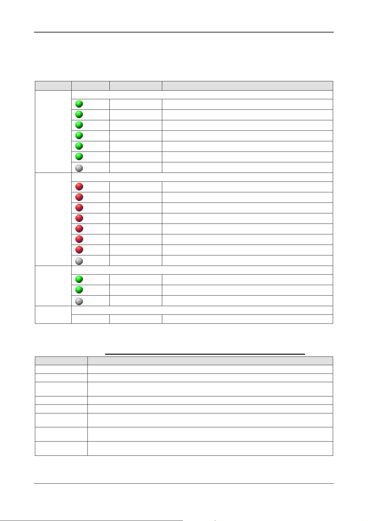
LED Descriptions 76/145
8.12 sercos Master
The subsequent table describes the meaning of the LEDs for the PC Card
cifX Real-Time Ethernet Master when the firmware of the sercos Master
protocol is loaded to the device.
LED Color State Meaning
STA
Name in
the device
drawing:
COM 0
ERR
Name in
the device
drawing:
COM 1
L/A/RJ45
Ch0 & Ch1
Ch0 & Ch1
Duo LED red/green
(green)
(green)
(green)
(green)
(green)
(green)
(off)
Blinking
Flickering
Single Flash
Double Flash
Triple Flash
On
Off
CP0: Communication phase 0
Master isn't configured and is in NRT. After a status change this
'
CP1: Communication phase 1
CP2: Communication phase 2
CP3: Communication phase 3
CP4: Communication phase 4
NRT: Non Real-time Mode
Duo LED red/green
(red)
(red)
(red)
(red)
(red)
(red)
(red)
(off)
Blinking Error in the configuration database.
Flickering Boot-up was stopped due to an error.
Single Flickering Channel Init was executed at the Master.
Quadruple Flash No Master license present in the device
Triple Flash DPM Watchdog has expire d.
Double Flash Internal Stop of the bus c ycle
Single Flash Bus Sync Error Threshold
Off No error
LED green
(green)
(green)
(off)
On Link: A connection to the Ethernet exists
Flashing Activity: The device sends/receives Ethernet frames
Off The device has no connection to the Ethernet
LED yellow RJ45
- - This LED is not used.
Table 51: LEDs sercos Master
LED State Definition for sercos Master for STA and ERR LEDs
Indicator state Definition
Off The indicator is constantly off.
Blinking The indicator turns on and off with a frequency of 2,5 Hz: on for 200 ms, followed by off for 200 ms.
Single Flickering The indicator turns on and off with a frequency of approximately 10 Hz: on for approximately 50 ms,
Flickering The indicator turns on and off once: on for approximately 50 ms, followed by off for 50 ms.
Single Flash The indicator shows one short flash (200 ms) followed by a long off phase (1,000 ms).
Double Flash The indicator shows a sequence of two short flashes (each 200 ms), separated by a short off phase (200
Triple Flash The indicator shows a sequence of three short flashes (each 200 ms), separated by a short off phase (200
Quadruple Flash The indicator shows a sequence of four short flashes (each 200 ms), separated by a short off phase (200
PC Cards cifX PCI, PCIe, Low Profile PCIe | Installation, Operation and Hardware Description
DOC120204UM36EN | Revision 36 | English | 2012-10 | Released | Public © Hilscher, 2008-2012
followed by off for 50 ms.
ms). The sequence is finished by a long off phase (1,000 ms).
ms). The sequence is finished by a long off phase (1,000 ms).
ms). The sequence is finished by a long off phase (1,000 ms).
Table 52: LED State Definition for sercos Master for the STA and ERR LEDs
Page 77

LED Descriptions 77/145
8.13 sercos Slave
The subsequent table describes the meaning of the LEDs for the cifX
Communication Interface Real-Time Ethernet Slave when the firmware of
the sercos Slave protocol is loaded to the device.
LED Color State Meaning
STA
Name in
the device
drawing:
COM 0
the device
drawing:
COM 1
L/A/RJ45
Ch0 & Ch1
Ch0 & Ch1
Duo LED red/green/orange (orange = red/green simultaneously)
(green)
(green)
(red/ green)
On
Flashing (4 Hz)
Flashing (4 Hz),
The LED
flashes at least
for 2 seconds
from red to
CP4: Communication phase 4,
Normal operation, no error
Loopback: The network state has changed from „fast-forward“ to
„loopback“.
Communication Error: Depends on IDN S-0-1003
(for details refer to sercos Slave Protocol API.pdf on the
product DVD).
Shows how long the Master may in the communication phases CP3
and CP4 not received Master SYNC telegrams.
green.
(red)
(orange)
(orange)
On
On
Flashing (4 Hz)
SIII C1D:
Error detected according to sercos third generation Cass 1 Diagnosis.
CP0 … CP3:
Communication phase 0 to Communication phase 3
Identification: Bit 15 in the Slave device control that indicates remote
address allocation or configuration errors between Master and Slaves
(for details refer to sercos Slave Protocol API.pdf on the
product DVD).
(off)
Off No sercos Communication
Duo LED red/green Name in
-
- This LED is not used.
LED green
(green)
(green)
(off)
On Link: A connection to the Ethernet exists
Flashing Activity: The device sends/receives Ethernet frames
Off The device has no connection to the Ethernet
LED yellow RJ45
-
- This LED is not used.
Table 53: LEDs sercos Slave
LED State Definition for sercos Slave for the S3 LED
Indicator state Definition
On The indicator is constantly on.
Off The indicator is constantly off.
Flashing (4 Hz)
PC Cards cifX PCI, PCIe, Low Profile PCIe | Installation, Operation and Hardware Description
DOC120204UM36EN | Revision 36 | English | 2012-10 | Released | Public © Hilscher, 2008-2012
The indicator turns on and off with a frequency of 4 Hz: on for appr. 125 ms, followed by off
for appr. 125 ms.
Table 54: LED State Definition for sercos Slave for the S3 LED
Page 78

LED Descriptions 78/145
8.14 VARAN Client (Slave)
The subsequent table describes the meaning of the LEDs for the PC Card
cifX Real-Time Ethernet Slave when the firmware of the VARAN Client
(Slave) protocol is loaded to the device.
LED Color State Meaning
RUN
Name in the
device
drawing:
COM 0
ERR
Name in the
device
drawing:
COM 1
Duo LED red/green
(off)
(green)
(green)
Duo LED red/green
(off)
(red)
(red)
Off Not configured.
Blinking Configured and communication is inactive.
On Configured and communication is active.
Off Configured.
Blinking Not configured.
On Communication error occurred.
LINK
RJ45
Ch0 & Ch1
ACT
RJ45
Ch0 & Ch1
LED green
(green)
(off)
LED yellow
(yellow)
On A connection to the Ethernet exists
Off The device has no connection to the Ethernet
Flashing The device sends/receives Ethernet frames
Table 55: LEDs VARAN Client
LED State Definition for VARAN Client for the RUN and ERR LEDs
Indicator state Definition
On The indicator is constantly on.
Off The indicator is constantly off.
Blinking
The indicator turns on and off with a frequency of 5 Hz: on for 100 ms, followed by off for
100 ms.
Table 56: LED State Definition for VARAN Client for the RUN and ERR LEDs
PC Cards cifX PCI, PCIe, Low Profile PCIe | Installation, Operation and Hardware Description
DOC120204UM36EN | Revision 36 | English | 2012-10 | Released | Public © Hilscher, 2008-2012
Page 79

LED Descriptions 79/145
8.15 PROFIBUS DP Master
The subsequent table describes the meaning of the LEDs for the PC Card
cifX PROFIBUS DP Master when the firmware of the PROFIBUS DP
Master protocol is loaded to the device.
LED Color State Meaning
cifX with 1 Communication LED (current Hardware Revision)
COM
Duo LED red/green
(green)
(green)
(green)
(red)
(red)
Flashing acyclic No configuration or stack error
Flashing cyclic
On Communication to all Slaves is established
Flashing cyclic Communication to at least one Slave is disconnected
On
Table 57: LEDs PROFIBUS DP Master – 1 Communication LED (current Hardware
Revision)
Note: For 2-Channel Devices per channel works 1 communication LED.
* Descriptions for 2-Communication LEDs of earlier device revisions are included in th e
user manual for PC cards cifX fieldbus up to manual rev. 23.
Profibus is configured, but bus communication is not yet released
from the application
Communication to one/all Slaves is disconnected or annother serious
error has occured.
Redundant Mode: The active Master was not found.
8.16 PROFIBUS DP Slave
The subsequent table describes the meaning of the LEDs for the PC Card
cifX PROFIBUS DP Slave when the firmware of the PROFIBUS DP Slave
protocol is loaded to the device.
LED Color State Meaning
cifX with 1 Communication LED (current Hardware Revision)
COM
Duo LED red/green
(green)
(red)
(red)
(red)
On RUN, cyclic communication
On Wrong configuration at PROFIBUS-DPside.
Flashing cyclic STOP, no communication, connection error
Flashing acyclic not configured
Table 58: LEDs PROFIBUS DP Slave – 1 Communication LED (current Hardware Revision)
* Descriptions for 2-Communication LEDs of earlier device revisions are included in th e
user manual for PC cards cifX fieldbus up to manual rev. 23.
PC Cards cifX PCI, PCIe, Low Profile PCIe | Installation, Operation and Hardware Description
DOC120204UM36EN | Revision 36 | English | 2012-10 | Released | Public © Hilscher, 2008-2012
Page 80

LED Descriptions 80/145
8.17 PROFIBUS MPI Device
The subsequent table describes the meaning of the LEDs for the PC Card
cifX PROFIBUS DP-Slave when the firmware of the PROFIBUS MPI
protocol is loaded to the device.
LED Color State Meaning
COM
Duo LED red/green
(green)
(green)
(green)
(red)
(off)
On
Blinking
(regularly)
5 Hz
Blinking
(regularly)
0.5 Hz
On
Off
Table 59: LEDs PROFIBUS MPI
Status
The device currently holds the PROFIBUS token and is able to transfer
telegrams of data.
Status
The device is configured to be a part of the PROFIBUS ring, but it must
share the PROFIBUS token with other PROFIBUS-Master devices
present on the PROFIBUS ring.
Status
Automatic baudrate detection is running
Error
Communication error at the PROFIBUS.
Status/Error
The device has not been integrated into the PROFIBUS ring, i.e. it has
not been configured correctly or has a wrong configuration or has not
received the PROFIBUS token.
PC Cards cifX PCI, PCIe, Low Profile PCIe | Installation, Operation and Hardware Description
DOC120204UM36EN | Revision 36 | English | 2012-10 | Released | Public © Hilscher, 2008-2012
Page 81

LED Descriptions 81/145
8.18 CANopen Master
The subsequent table describes the meaning of the LEDs for the PC Card
cifX CANopen Master when the firmware of the CANopen Master protocol
is loaded to the device.
LED Color State Meaning
cifX with 1 Communication LED (current Hardware Revision)
CAN
Duo LED red/green
(off)
(green)
(green)
(green)
(red)
(red)
(red)
Off
Single flash
Blinking
On
Single flash
Double flash
On
Table 60: LEDs CANopen Master – 1 Communication LED (current Hardware Revision)
RESET: The device is executing a reset
STOPPED: The device is in STOPPED state
PREOPERATIONAL: The device is in the PREOPERATIONAL state
OPERATIONAL: The device is in the OPERATIONAL state
Warning Limit reached: At least one of the error counters of the CAN
controller has reached or exceeded the warning level (too many error
frames).
Error Control Event: A guard event (NMT Slave or NMT-master) or a
heartbeat event (Heartbeat consumer) has occurred.
Bus Off: The CAN controller is bus off
LED State Definition for CANopen Master for the CAN LED
Indicator state Definition
On The indicator is constantly on.
Off The indicator is constantly off.
Flickering
The indicator turns on and off with a frequency of 10 Hz: on for 50 ms, followed by off for 50
ms.
Blinking
The indicator turns on and off with a frequency of 2,5 Hz: on for 200 ms, followed by off for
200 ms.
Single Flash The indicator shows one short flash (200 ms) followed by a long off phase (1,000 ms).
Double Flash
The indicator shows a sequence of two short flashes (each 200 ms), separated by a short off
phase (200 ms). The sequence is finished by a long off phase (1,000 ms).
Table 61: LED State Definition for CANopen Master for the CAN LED
* Descriptions for 2-Communication LEDs of earlier device revisions are included in th e
user manual for PC cards cifX fieldbus up to manual rev. 23.
PC Cards cifX PCI, PCIe, Low Profile PCIe | Installation, Operation and Hardware Description
DOC120204UM36EN | Revision 36 | English | 2012-10 | Released | Public © Hilscher, 2008-2012
Page 82

LED Descriptions 82/145
8.19 CANopen Slave
The subsequent table describes the meaning of the LEDs for the PC Card
cifX CANopen Slave when the firmware of the CANopen Slave protocol is
loaded to the device.
LED Color State Meaning
cifX with 1 Communication LED (current Hardware Revision)
CAN
Duo LED red/green
(off)
(green)
(green)
(green)
(red/green)
(red)
(red)
(red)
Off
Single flash
Blinking
On
Flickering
(alternatively
red / green)
Single flash
Double flash
On
Table 62: LEDs CANopen Slave – 1 Communication LED (current Hardware Revisio n)
RESET: The device is executing a reset
STOPPED: The device is in STOPPED state
PREOPERATIONAL: The device is in the PREOPERATIONAL state
OPERATIONAL: The device is in the OPERATIONAL state
Auto Baud Rate Detection active: The Device is in the Auto Baud Rate
Detection mode
Warning Limit reached: At least one of the error counters of the CAN
controller has reached or exceeded the warning level (too many error
frames).
Error Control Event: A guard event (NMT Slave or NMT-master) or a
heartbeat event (Heartbeat consumer) has occurred.
Bus Off: The CAN controller is bus off
LED State Definition for CANopen Slave for the CAN LED
Indicator state Definition
On The indicator is constantly on.
Off The indicator is constantly off.
Flickering
The indicator turns on and off with a frequency of 10 Hz: on for 50 ms, followed by off for 50
ms.
Blinking The indicator turns on and off with a frequency of 2,5 Hz: on for 200 ms, followed by off for 200 ms.
Single Flash The indicator shows one short flash (200 ms) followed by a long off phase (1,000 ms).
Double Flash The indicator shows a sequence of two short flashes (each 200 ms), separated by a short off phase (200
ms). The sequence is finished by a long off phase (1,000 ms).
Table 63: LED State Definition for CANopen Slave for the CAN LED
* Descriptions for 2-Communication LEDs of earlier device revisions are included in th e
user manual for PC cards cifX fieldbus up to manual rev. 23.
PC Cards cifX PCI, PCIe, Low Profile PCIe | Installation, Operation and Hardware Description
DOC120204UM36EN | Revision 36 | English | 2012-10 | Released | Public © Hilscher, 2008-2012
Page 83

LED Descriptions 83/145
8.20 DeviceNet Master
The subsequent table describes the meaning of the LEDs for the PC Card
cifX DeviceNet Master when the firmware of the DeviceNet Master protocol
is loaded to the device.
LED Color State Meaning
MNS
Duo LED red/green
(green)
(green)
(green/red/off)
(red)
(red)
On Device is online and has established one or more connections
Flashing Device is online and has established no connection
Green/Red/Off
On
Flashing Connection timeout
Selftest after power on:
Green on for 0,25 s, then red on for 0,25 s, then off
Critical connection failure; device has detected a network error:
duplicate MAC-ID or severe error in CAN network (CAN-bus off)
(off)
Off
Device is not powered/Device is not on-line.
- The device has not completed the Dup_MAC_ID test yet.
- The device may not be powered.
Table 64: LEDs DeviceNet Master
8.21 DeviceNet Slave
The subsequent table describes the meaning of the LEDs for the PC Card
cifX DeviceNet Slave when the firmware of the DeviceNet Slave protocol is
loaded to the device.
LED Color State Meaning
MNS
Duo LED red/green
(green)
(green)
(green/red/off)
(red)
(red)
(off)
On Device is online and has established one or more connections
Flashing Device is online and has established no connection
Green/Red/Off
On
Flashing Connection timeout
Off
Table 65: LEDs DeviceNet Slave
Selftest after power on:
Green on for 0,25 s, then red on for 0,25 s, then off
Critical connection failure; device has detected a network error:
duplicate MAC-ID or severe error in CAN network (CAN-bus off)
Device is not powered/Device is not on-line.
- The device has not completed the Dup_MAC_ID test yet.
- The device may not be powered.
PC Cards cifX PCI, PCIe, Low Profile PCIe | Installation, Operation and Hardware Description
DOC120204UM36EN | Revision 36 | English | 2012-10 | Released | Public © Hilscher, 2008-2012
Page 84

LED Descriptions 84/145
8.22 AS Interface Master
The subsequent table describes the meaning of the LED for the PC Card
cifX AS Interface Master when the firmware of the AS Interface Master
protocol is loaded to the device.
LED Color State Meaning
CH0
CH1
Duo LED red/green
(green)
(green)
(green)
(red/green)
(red)
(red)
(off)
Duo LED red/green
On No configuration error, data exchange active
Flashing Configuration error, data exchange active
Flashing fast The Communic ation is stop ped.
Flashing „Configuration mode“ active
Flashing AS-Interface power fail
On Heavy System error or hardware failure
Off No configuration found for this channel
(green)
(green)
(green)
(red/green)
(red)
(red)
(off)
Table 66: LEDs AS Interface Master
On No configuration error, data exchange active
Flashing Configuration error, data exchange active
Flashing fast The Communic ation is stop ped.
Flashing „Configuration mode“ active
Flashing AS-Interface power fail
On Heavy System error or hardware failure
Off No configuration found for this channel
8.23 CC-Link Slave
The subsequent table describes the meaning of the LEDs for the PC Card
cifX CC-Link Slave when the firmware of the CC-Link Slave protocol is
loaded to the device.
LED Color State Meaning
L RUN
L ERR
LED green
(off)
(green)
LED green
Off
On
1. Before participating in the network
2. Unable to detect carrier
3. Timeout
4. Resetting hardware
Receive both refresh and polling signals or just the refresh signal normally,
after participating in the network.
(off)
(red)
(red)
PC Cards cifX PCI, PCIe, Low Profile PCIe | Installation, Operation and Hardware Description
DOC120204UM36EN | Revision 36 | English | 2012-10 | Released | Public © Hilscher, 2008-2012
Off
Blinking
On
Table 67: LEDs CC-Link Slave
1. Normal communication
2. Resetting hardware
The switch setting has been changed from the setting at the reset
cancellation (blinks for 0.4 sec.).
1. CRC error
2. Address parameter error (0, 65 or greater is set including the number of
occupied stations)
3. Baud rate switch setting error during cancellation of reset (5 or greater)
Page 85

LED Descriptions 85/145
8.24 CompoNet Slave
The subsequent table describes the meaning of the LEDs for the PC Card
cifX CompoNet Slave when the firmware of the CompoNet Slave protocol is
loaded to the device.
LED Color State Meaning
MS
NS
Duo LED red/green
(off)
(green)
(green)
(red)
(red)
(red/green)
Off
On
Flashing
Flashing
On
Flashing
Duo LED red/green
(off)
(red/green)
(green)
(green)
(red)
(red)
Off
Flashing
Flashing
On
Flashing
On
No Power: If no power is supplied to the device, the MS LED shall be steady
off.
Operational: If the device is operating in a normal condition, the MS LED shall
be steady green.
Standby (Device needs commissioning): If the device needs commissioning
due to configuration is missing, incomplete or incorrect, the MS LED shall be
flashing green.
Minor Fault: If the device has detected a recoverable minor fault, the MS LED
shall be flashing red.
NOTE: An incorrect or inconsistent configuration would be considered a minor
fault.
Unrecoverable Fault: If the device has detected a non-recoverable major
fault, the MS LED shall be steady red. It may be necessary to replace the
Slave device.
Device Self Test: While the device is performing its self test, the MS LED shall
be flashing green/red.
No power / Speed Detection: If no power is supplied to the device or the
network data rate is checked, the NS LED shall be steady off.
Device Self Testing: While the device is performing its self test, the NS LED
shall be flashing green/red.
Non-participated / Participated: If the data rate is known and the Slave is
waiting for the STW (status write operation) signal and the Allocate signal, the
NS LED shall be flashing green.
Participated: If the Slave has been allocated by the Master and an I/O
connection is established, the NS LED shall be steady green.
Non-participated / Speed Detection: If an I/O connection timeout or an
network timeout is detected, the NS LED shall be flashing red.
Communication fault: If a “Duplication MAC ID” failure has been deteced, the
NS LED shall be steady red.
Table 68: LEDs CompoNet Slave
PC Cards cifX PCI, PCIe, Low Profile PCIe | Installation, Operation and Hardware Description
DOC120204UM36EN | Revision 36 | English | 2012-10 | Released | Public © Hilscher, 2008-2012
Page 86

Device Connections and Switches 86/145
9 Device Connections and Switches
9.1 Ethernet Interface
For the Ethernet interface use RJ45 plugs and twisted pair cable of
category 5 (CAT5) or higher, which consists of 4 twisted cores and has a
maximum transmission rate of 100 MBit/s (CAT5).
9.1.1 Ethernet Pin Assignment at the RJ45 Socket
Note: The device supports the Auto Crossover function. Due to this fact
RX and TX can be switched. The following figure shows the RJ45
standard pin assignment.
Figure 25: Ethernet Pin Assignment at the RJ45 Socket for cifX or AIFX
Pin Signal Meaning
1 TX+ Transmit Data +
2 TX– Transmit Data –
3 RX+ Receive Data +
4 Term 1
5 Term 1
6 RX– Receive Data –
7 Term 2
8 Term 2
* Bob Smith Termination
Table 69: Ethernet Pin Assignment at the RJ45 Socket for cifX or AIFX
Further Notes:
(1) The RJ45 socket is only for use in LAN, not for telecommunication circuits.
(2) With loaded EtherCAT Master firmware only the RJ-45 channel 0 can be used, the
channel 1 is deactivated. For the Open Modbus/TCP firmware with V2.3.4.0 and higher
both RJ-45 RJ-45channels can be used.
Connected to each other and
terminated to PE through RC circuit*
Connected to each other and
terminated to PE through RC circuit*
PC Cards cifX PCI, PCIe, Low Profile PCIe | Installation, Operation and Hardware Description
DOC120204UM36EN | Revision 36 | English | 2012-10 | Released | Public © Hilscher, 2008-2012
Page 87

Device Connections and Switches 87/145
9.1.2 Ethernet Connection Data
Medium
Length of cable
Transmission rate
2 x 2 Twisted-Pair cupric cable, CAT5 (100 MBit/s)
Typ. 100 m
10 MBit/s/100 MBit/s
Table 70: Ethernet Connection Data
9.1.3 Use of Hubs and Switches
The specifications on the Use of Hubs and Switches are only valid for the
PC cards cifX as follows:
PC Cars cifX Part No up to Serial Number
CIFX 50-RE 1250.100 22414
CIFX 50E-RE 1251.100 20167
For the corresponding communication systems, the use of hubs and/or
switches is either forbidden or allowed. The following table shows the
acceptable use of hubs and switches by each communication system:
Communication System Hub Switch
EtherCAT
EtherNet/IP
Open Modbus/TCP
POWELINK
PROFINET IO RT
sercos
VARAN*
forbidden
allowed
allowed
allowed forbidden
forbidden
forbidden forbidden
forbidden forbidden
Table 71: Use of Hubs and Switches
only allowed between EtherCAT Master and first EtherCAT Slave
(100 MBit/s, Full Duplex)
allowed
(10 MBit/s/100 MBit/s, Full or Half Duplex, Auto-Negotiation)
allowed
(10 MBit/s/100 MBit/s, Full or Half Duplex, Auto-Negotiation)
Only allowed if the switch supports ‚Priority Tagging’ and LLDP
(100 MBit/s, Full Duplex)
*Instead of hubs and switches VARAN uses splitter. [3]
Failure of the Network Communication
Do not operate hardware with the communication controllers netX 50,
netX100 or netX 500 with the protocols Ethernet TCP/UDP/IP,
EtherNet/IP or Modbus TCP at 10 MBit/s in half-duplex mode, otherwise
failure of the network communication can occur.
Use only switches or 10/100 MBit/s dual-speed hubs and ensure that
the network operates at 100 MBit/s and in full-duplex mode.
For further information refer to section Failure in 10 MBit/s Half Duplex
Mode and Workaround on page
PC Cards cifX PCI, PCIe, Low Profile PCIe | Installation, Operation and Hardware Description
DOC120204UM36EN | Revision 36 | English | 2012-10 | Released | Public © Hilscher, 2008-2012
65.
Page 88

Device Connections and Switches 88/145
9.2 PROFIBUS Interface
Isolated RS-485 interface:
Figure 26: PROFIBUS Interface (DSub female connector, 9 pin), X400
Connection with
DSub female
connector
3 RxD/TxD-P
5 DGND Reference potential
6 VP Positive supply voltage
8 RxD/TxD-N
Table 72: PROFIBUS Interface, X400
Signal Meaning
Receive/Send Data-P respectively
connection B plug
Receive/Send Data-N respectively
connection A plug
9.3 CANopen Interface
Isolated ISO 11898 interface:
Figure 27: CANopen Interface (DSub male connector, 9 pin), X400
Connection with
DSub male
connector
2 CAN_L CAN_Low Bus Line
3 CAN_GND CAN Ground
7 CAN_H CAN High Bus Line
1, 4, 5, 6, 8, 9
Table 73: CANopen Interface, X400
Signal Description
Do not connect!
PC Cards cifX PCI, PCIe, Low Profile PCIe | Installation, Operation and Hardware Description
DOC120204UM36EN | Revision 36 | English | 2012-10 | Released | Public © Hilscher, 2008-2012
Page 89

Device Connections and Switches 89/145
9.4 DeviceNet Interface
Isolated ISO 11898 interface:
Figure 28: DeviceNet Interface (CombiCon male Connector, 5 pin), X360
Connection
with
CombiCon
male
connector
1 V- Black Reference potential DeviceNet supply voltage
2 CAN_L Blue CAN Low-Signal
3 Drain
4 CAN_H White CAN High-Signal
5 V+ Red +24 V DeviceNet supply voltage
Table 74: DeviceNet Interface, X360
Signal Color Description
Shield
9.5 AS-Interface Interface
The AS-Interface Master conforms to Complete Specification 2.11 (Annex
B, Version 2.0) the profile M3 (Full Extended Master).
AS-Interface interface according to IEC 364-4-41.
Figure 29: AS-Interface Interface (CombiCon male Connector, 2 pin)
Connection
with
CombiCon
male
connector
1 AS-i + AS-Interface positive voltage
2 AS-i - AS-Interface negative voltage
Table 75: AS-Interface Interface
Signal Description
PC Cards cifX PCI, PCIe, Low Profile PCIe | Installation, Operation and Hardware Description
DOC120204UM36EN | Revision 36 | English | 2012-10 | Released | Public © Hilscher, 2008-2012
Page 90

Device Connections and Switches 90/145
9.6 CC-Link Interface
Isolated RS-485 interface:
Figure 30: CC-Link Interface (Screw terminal connector, 5 pin)
Connection with
Screw terminal
Connector
1 DA Data A
2 DB Data B
3 DG Data Ground
4 SLD Shield
5 FG Field Ground
Table 76: CC-Link Interface
Signal Meaning
9.7 CompoNet Interface
Drawing of the CompoNet Interface
The following drawing shows the CompoNet interface:
Open Jack connector, 4-pin (according to CompoNet Specification)
Figure 31: CompoNet Interface (Open Jack Connector, 4-pin)
Connection with
Open Jack
connector (pin)
1 BS+ Red CompoNet positive voltage
2 BDH White CompoNet-High Bus Line
3 BDL Blue CompoNet-Low Bus Line
4 BS- Black CompoNet negative voltage
Table 77: CompoNet Interface
Signal Color Description Terminal
PC Cards cifX PCI, PCIe, Low Profile PCIe | Installation, Operation and Hardware Description
DOC120204UM36EN | Revision 36 | English | 2012-10 | Released | Public © Hilscher, 2008-2012
Page 91

Device Connections and Switches 91/145
9.8 Rotary Switch for Slot Number (Card ID)
Device revisions equipped with a Rotary Switch Slot Number (Card ID)
are listed separately in section
14.
The Rotary Switch Slot Number (Card ID) serves to set the Slot Number
(Card ID) of the PC Cards cifX.
The figure below describes possible switch positions of the Rotary Switch
Slot Number (Card ID).
Switch Position Meaning
0 The value 0 means:
no Slot Number (Card ID), i. e. the Slot Number (Card ID) is not used,
for downwards compatibility purposes,
characterizes PC Cards cifX not equipped with a Rotary Switch Slot Number (Card ID);
i. e. these PC Cards cifX are identified via its device number and serial number.
Example
Rotary Switch Slot Number (Card ID) Switch Position 0
1 … 9
corresponds to the Slot Number (Card ID) 1 … 9
Example
Rotary Switch Slot Number (Card ID) Switch Position 1
Hardware: PC Cards cifX in Table 2 on page
Table 78: Rotary Switch for Slot Number (Card ID), S1
9.8.1 Set Slot Number (Card ID)
If the Slot Number (Card ID) shall not be used:
¾ set the value 0.
Or
If the Slot Number (Card ID) shall be used:
¾ Set a value from 1 to 9.
For further information about the Slot Number (Card ID) refer to section
The Function „Slot Number (Card ID)“ (page 24) or to the user manual
Software Installation for the PC Cards cifX, sections Slot Number (Card ID)
in the cifX Device Driver Setup and Slot Number (Card ID) in the Configuration Software.
9.8.2 Note for Device Exchange Service (Replacement Case):
Important: For PC Cards cifX with
ID) in terms of a device exchange service (replacement case) you must
set at the replacement card cifX the same Slot Number (Card ID) as at
the preceding cifX. Then the same firmware and configuration is loaded
into the replacement card cifX, as into the preceding cifX.
Rotary Switch Slot Number (Card
PC Cards cifX PCI, PCIe, Low Profile PCIe | Installation, Operation and Hardware Description
DOC120204UM36EN | Revision 36 | English | 2012-10 | Released | Public © Hilscher, 2008-2012
Page 92

Device Connections and Switches 92/145
9.8.3 Rotary Switch Slot Number PC Cards cifX Low Profile
The Table 79 below shows the Rotary Switch Slot Number (Card ID) of
the PC Cards cifX Low Profile PCI Express in switch position 0 and 1.
Description
Rotary Switch Slot Number (Card ID) Switch Position 0
Rotary Switch Slot Number (Card ID) Switch Position 1
Table 79: Rotary Switch Slot Number (Card ID) PC Cards cifX Low Profile PCI Express
PC Cards cifX PCI, PCIe, Low Profile PCIe | Installation, Operation and Hardware Description
DOC120204UM36EN | Revision 36 | English | 2012-10 | Released | Public © Hilscher, 2008-2012
Page 93

Device Connections and Switches 93/145
9.9 SYNC Connector (Pin-Assignment, Hardware/Firmware)
9.9.1 Pin Assignment SYNC Connector, X51 (CIFX 50 50E 70E)
Only for:
CIFX 50-RE (since hardware Rev. 3), CIFX 50E-RE, CIFX 70E-RE
Pin Signal
1
GND
2
IO_SYNC0
3
IO_SYNC1
Table 80: Pin Assignment for SYNC Connector, X51
9.9.2 Pin Assignment SYNC Connector, J3 (CIFX 100EH)
Only for: CIFX 100EH-RE\CUBE.
Pin
Signal
IO_SYNC0
1
2 Jumper set:
Jumper not set:
IO_SYNC1
3
Table 81: Pin Assignment for SYNC Connector, J3
SYNC signal is transferred to the PCI Express Bus Pin B24*
static high 3,3 V (with pull-up)
Note! *
• If the jumper is set on Pin1-Pin2
, then the IO_SYNC0 signal will be
transferred to the PCI Express Bus X2 (pin B24).
Or
• If the jumper is set on Pin2-Pin3
, then the IO_SYNC1 signal will be
transferred to the PCI Express Bus X2 (pin B24).
Or
• If the no jumpe
r is set, then the signal at the PCI Express Bus X2 pin
B24 will be static High 3,3 V (with pull-up).
Compare section
RE\CUBE on page
Pin Assignment for PCI Express Bus CIFX 100EH-
96.
PC Cards cifX PCI, PCIe, Low Profile PCIe | Installation, Operation and Hardware Description
DOC120204UM36EN | Revision 36 | English | 2012-10 | Released | Public © Hilscher, 2008-2012
Page 94

Device Connections and Switches 94/145
9.9.3 Items on Hardware
Item Explanation
SYNC Signal 3,3 V (LVTTL), maximum load 6 mA
Connector
SYNC connector, X51
Connector, X51 on page
(for the PC Cards cifX, as indicated under section Pin Assignment SYNC
93.)
Female connector, 3 pin, pitch spacing 1.25 mm (for example, the type Molex series 51021)
and female crimp contacts in design (e. g. type Molex series 50079/50058)
SYNC connector, J3
(for CIFX 100EH-RE\CUBE)
Male Connector with jumper, 3 pin, pitch spacing 2,54 mm
Max. Cable
Length
Recommendation: Max. 50 mm
Note: Take EMC into consideration for the cable laying
Table 82: SYNC Connector: SYNC Signal, Connector, Max. Cable Length
9.9.4 Items on Firmware
The firmware determines the input signal or output signal. The following
table shows the meaning of the SYNC signals for each protocol.
Protocol Signal IO_SYNC0
Input/Output
EtherCAT Slave SYNC 0
Output
sercos Master
External trigger to start bus
cycle
Input
Rising edge
sercos Slave CON_CLK
Output
Table 83: Meaning of the SYNC Signals for each Protocol
Signal IO_SYNC1
Input/Output
SYNC 1
Output
- 2.0.8.0 -
DIV_CLK
Output
From
Remarks
Firmware
Version
- Configurable
3.0.10.0 Configurable
PC Cards cifX PCI, PCIe, Low Profile PCIe | Installation, Operation and Hardware Description
DOC120204UM36EN | Revision 36 | English | 2012-10 | Released | Public © Hilscher, 2008-2012
Page 95

Device Connections and Switches 95/145
9.10 Pin Assignment at the Bus
9.10.1 Overview on the Pin Assignment at the Bus
For the PC Cards cifX PCI, PCI Express and Low Profile PCI Express the table
below gives an overview about the pin assignment at the bus.
CIFX 50-RE
CIFX 50-DP
CIFX 50-2DP
CIFX 50-CO
CIFX 50-DN
CIFX 50-2ASM
CIFX 50-CC
CIFX 50-CP
CIFX 50E-RE
CIFX 50E-DP
CIFX 50E-CO
CIFX 50E-DN
CIFX 50E-2ASM
CIFX 50E-CC
CIFX 50E-CP
CIFX 70E-RE,
CIFX 70E-DP,
CIFX 70E-CO,
CIFX 70E-DN
CIFX 100EH-RE\
CUBE
Hardwar
Revision
5
5
2
5
5
2
2
2
5
6
5
5
5
4
4
1
1
1
1
4
Bus
Type
Bus
[Pins]
Pin Assignment at the Bus PC Card cifX
acc. to
standard
PCI 124
yes
PCI
36
yes
Express
PCI
64
no
Express
Table 84: Pin Assignment at the Bus
Standard
compare section, page
Bus
Specification
- [bus spec 1]
-
[bus spec 2,
Rev. 2.0],
[bus spec 3]
Pin Assignment for PCI Express Bus
CIFX 100EH-RE\CUBE, 96
[bus spec 2,
Rev. 2.0],
[bus spec 3]
9.10.2 References to the Bus Specifications PCI, PCI Express
No. Standard Bus Specification Revision Version Date www
[bus spec 1] PCI Local Bus Specification 2.3 - February 21, 2003 pcisig.com
[bus spec 2] PCI Express® Base Specification 2.0 - January 15, 2007
[bus spec 3]
PCI Express
Specification
®
Card Electromechanical
2.0 - April 11, 2007
Table 85: References to the Standard Bus Specifications PCI, PCI Express
PC Cards cifX PCI, PCIe, Low Profile PCIe | Installation, Operation and Hardware Description
DOC120204UM36EN | Revision 36 | English | 2012-10 | Released | Public © Hilscher, 2008-2012
Page 96

Device Connections and Switches 96/145
9.10.3 Pin Assignment for PCI Express Bus CIFX 100EH-RE\CUBE
Only for: CIFX 100EH-RE\CUBE (x1 = One Lane)4
PCI Express Bus X2 (Side B) PCI Express Bus X1 (Side A)
Pin Name Description Pin Name Description
B1 n. u. (not used) A1 PRSNT1# Hot-Plug presence detect
B2 n. u. (not used) A2 n. u. (not used)
B3 n. u. (not used) A3 n. u. (not used)
B4 GND Ground A4 GND Ground
B5 n. u. (not used) A5 JTAG-TCK JTAG Test Clock
B6 n. u. (not used) A6 JTAG-TDI JTAG Test Data Input
B7 GND Ground A7 JTAG-TDO JTAG Test Data Output
B8 3V3 3,3V Power A8 JTAG-TMS JTAG Test Mode Select Input
B9 JTAG-TRST# JTAG Test Reset A9 3V3 3,3V Power
B10 n. v. (not used) A10 3V3 3,3V Power
B11 n. u. (not used) A11 PERST# PCIe Reset
Key
B12 n. u. (not used) A12 GND Ground
B13 GND Ground A13 PCIe_CLK+
B14 PCIe_TP A14 PCIe_CLKB15 PCIe_TN
Transmitter Lane,
differential pair
A15 GND Ground
B16 GND Ground A16 PCIe_RP
B17 PRSNT2# Hot-Plug presence detect A17 PCIe_RN
B18 GND Ground A18 GND Ground
B19 n. u. (not used) A19 n. u. (not used)
B20 n. u. (not used) A20 n. u. (not used)
B21 n. u. (not used) A21 n. u. (not used)
B22 n. u. (not used) A22 n. u. (not used)
B23 GND Ground A23 n. u. (not used)
B24
IO_SYNC0 /
IO_SYNC1 / 3,3V
Real-Time Ethernet SYNC6 A24 n. u. (not used)
5
B25 GND Ground A25 n. u. (not used)
B26 SPI_CS# ID Chip Select A26 n. u. (not used)
B27 SPI_MOSI ID Slave In A27 n. u. (not used)
B28 SPI_MISO ID Slave Out A28 n. u. (not used)
B29 SPI_CLK ID Clock A29 n. u. (not used)
B30 GND Ground A30 n. u. (not used)
B31 n. u. (not used) A31 n. u. (not used)
B32 n. u. (not used) A32 n. u. (not used)
Table 86: Pin Assignment for PCI Express-Bus CIFX 100EH-RE\CUBE
PCIe Clock
differential pair
Receiver Lane,
differential pair
4
Pinning A19 to A32 / B19 to B32 not standard conform [bus spec 3, page 73-74].
5
If at the SYNC connector J3 the jumper is set, the IO_SYNC signal is transferred
to the PCI Express Bus X2 pin B24 (jumper on pin1-pin2(J3): IO_SYNC0, pin2-
pin3(J3): IO_SYNC1). If no jumper is set, the signal is 3,3V static High
Refer to section Pin Assignment SYNC Connector, J3, on page 93.
6
in 3V3 logic.
PC Cards cifX PCI, PCIe, Low Profile PCIe | Installation, Operation and Hardware Description
DOC120204UM36EN | Revision 36 | English | 2012-10 | Released | Public © Hilscher, 2008-2012
(with Pull-up).
Page 97

Technical Data 97/145
10 Technical Data
10.1 Technical Data PC Cards cifX
Note: All technical data are temporarily and can be altered without notice.
10.1.1 CIFX 50-RE
Item
System Interface
(Bus Type)
Dual-Port Memory Size
Function
Communication
Protocols EtherCAT Master, EtherCAT Slave,
Ethernet Frame Types
Processor
LEDs SYS, COM 0, COM 1, 2x Link, 2x Activity;
Rotary Switch Slot Number
(Card ID)
Configuration Software
Ethernet Interface RJ45 Socket, 10 Base-T, 100 Base-TX, potential free;
Transmission Rate 10/100 MBit/s, Auto-Negotiation, Auto-Cross-Over, Halfduplex/Fullduplex (100
CIFX 50-RE
PCI, according to [bus spec 1], (refer to section
Assignment at the Bus, page
the Dual-Port Memory (DPM), or IO-DMA (Direct Memory Access)
64 KBytes
Communication interface with PCI and Ethernet interface
Determined by the loaded firmware
EtherNet/IP Scanner (Master),
EtherNet/IP Adapter (Slave),
Open Modbus/TCP,
Powerlink Controlled Node/Slave,
Ethernet II
netX 500
(refer also to chapter
To set the Slot Number (Card ID)
SYCON.net (Master and Slave) or netX Configuration Tool (only Slave)
(refer also to section
MBit/s); depending on used firmware
LED Descriptions, page 66).
Ethernet Interface, page 86).
95), 33 MHz, 32-Bit width for the data access to
Overview on the Pin
PROFINET IO Controller (Master),
PROFINET IO Device (Slave),
sercos Master, sercos Slave,
VARAN Client (Slave)
Supply Voltage
Dimensions (L x W x D) Beginning with hardware revision 3: 120,0 x 86 x 18,5 mm;
Operating Temperature
Environment
UL Certification
Table 87: Technical Data CIFX 50-RE
+3.3 V dc ±5 %/Typ. 650 mA
[W = 86 mm, as with Rotary Switch Slot Number (Card ID)].
-20 °C ... +55 °C
The device must be used in a pollution degree 2 environment.
The device is UL 508 certified (UL-File No E221530).
PC Cards cifX PCI, PCIe, Low Profile PCIe | Installation, Operation and Hardware Description
DOC120204UM36EN | Revision 36 | English | 2012-10 | Released | Public © Hilscher, 2008-2012
Page 98

Technical Data 98/145
10.1.2 CIFX 50-DP
Item
System Interface
(Bus Type)
Dual-Port Memory Size
Function
Communication
Protocols
Processor
LEDs SYS, COM;
Rotary Switch Slot Number
(Card ID)
Configuration Software
PROFIBUS Interface DSub female Connector, 9 pin; Isolated RS-485 Interface;
Supply Voltage
Dimensions (L x W x D) Beginning with hardware revision 5: 120,0 x 86 x 18,5 mm;
Operating Temperature
Environment
UL Certification
CIFX 50-DP
PCI, according to [bus spec 1], (refer to section
Assignment at the Bus, page
the Dual-Port Memory (DPM), or IO-DMA (Direct Memory Access)
64 KByte
Communication interface with PCI and PROFIBUS interface
Determined by the loaded firmware
PROFIBUS DP Master, PROFIBUS DP Slave, PROFIBUS MPI Device
netX 100
(refer also to chapter
To set the Slot Number (Card ID)
SYCON.net (Master and Slave) or netX Configuration Tool (only Slave)
(refer also to chapter
+3.3 V dc ±5 %/Typ. 650 mA
[W = 86 mm, as with Rotary Switch Slot Number (Card ID)].
-20 °C ... +55 °C
The device must be used in a pollution degree 2 environment.
The device is UL 508 certified (UL-File No E221530).
LED Descriptions, page 66).
PROFIBUS Interface page 88).
95), 33 MHz, 32-Bit width for the data access to
Overview on the Pin
Table 88: Technical Data CIFX 50-DP
10.1.3 CIFX 50-2DP
Item
System Interface
(Bus Type)
Dual-Port Memory Size
Function
Communication
Protocols
Processor
LEDs SYS, COM1, COM2;
Configuration Software
PROFIBUS Interface 2 x DSub female Connector, 9 pin; Isolated RS-485 Interface;
Supply Voltage
Dimensions (L x W x D)
Operating Temperature
Environment
CIFX 50-2DP
PCI, according to [bus spec 1], (refer to section
Assignment at the Bus, page
the Dual-Port Memory (DPM), or IO-DMA (Direct Memory Access)
64 KByte
Communication interface with PCI and 2 x PROFIBUS interface
Determined by the loaded firmware
PROFIBUS DP Master, PROFIBUS DP Slave
netX 100
(refer also to chapter
SYCON.net (Master and Slave) or netX Configuration Tool (only Slave)
(refer also to chapter
+3.3 V dc ±5 %/Typ. 750 mA
120 x 94,5 x 18,5 mm
-20 °C ... +55 °C
The device must be used in a pollution degree 2 environment.
LED Descriptions, page 66).
PROFIBUS Interface page 88).
95), 33 MHz, 32-Bit width for the data access to
Overview on the Pin
UL Certification
Table 89: Technical Data CIFX 50-2DP
PC Cards cifX PCI, PCIe, Low Profile PCIe | Installation, Operation and Hardware Description
DOC120204UM36EN | Revision 36 | English | 2012-10 | Released | Public © Hilscher, 2008-2012
The device is UL 508 certified (UL-File No E221530).
Page 99

Technical Data 99/145
10.1.4 CIFX 50-CO
Item
System Interface
(Bus Type)
Dual-Port Memory Size
Function
Communication
Protocols
Processor
LEDs
Rotary Switch Slot Number
(Card ID)*
Configuration Software
CANopen Interface DSub male Connector, 9 pin; Isolated ISO-11898 Interface;
Supply Voltage
Dimensions (L x W x D) Beginning with hardware revision 5: 120,0 x 86 x 18,5 mm;
Operating Temperature
Environment
UL Certification
CIFX 50-CO
PCI, according to [bus spec 1], (refer to section
Assignment at the Bus, page
the Dual-Port Memory (DPM), or IO-DMA (Direct Memory Access)
64 KByte
Communication interface with PCI and CANopen interface
Determined by the loaded firmware
CANopen Master, CANopen Slave
netX 100
SYS, CAN; (refer also to chapter
To set the Slot Number (Card ID)
SYCON.net (Master and Slave) or netX Configuration Tool (only Slave)
(refer also to chapter
+3.3 V dc ±5 %/Typ. 650 mA
[W = 86 mm, as with Rotary Switch Slot Number (Card ID)].
-20 °C ... +55 °C
The device must be used in a pollution degree 2 environment.
The device is UL 508 certified (UL-File No E221530).
CANopen Interface, page 88).
95), 33 MHz, 32-Bit width for the data access to
LED Descriptions, page 66).
Overview on the Pin
Table 90: Technical Data CIFX 50-CO
10.1.5 CIFX 50-DN
Item
System Interface
(Bus Type)
Dual-Port Memory Size
Function
Communication
Protocols
Processor
LEDs
Rotary Switch Slot Number
(Card ID)*
Configuration Software
DeviceNet Interface CombiCon male Connector, 5 pin; Isolated ISO-11898 Interface according to
Supply Voltage
Dimensions (L x W x D) Beginning with hardware revision 5: 120,0 x 86 x 18,5 mm;
Operating Temperature
Environment
CIFX 50-DN
PCI, according to [bus spec 1], (refer to section
Assignment at the Bus, page
the Dual-Port Memory (DPM), or IO-DMA (Direct Memory Access)
64 KByte
Communication interface with PCI and DeviceNet interface
Determined by the loaded firmware
DeviceNet Master, DeviceNet Slave
netX 100
SYS, MNS; (refer also to chapter
To set the Slot Number (Card ID)
SYCON.net (Master and Slave) or netX Configuration Tool (only Slave)
DeviceNet specification;
(refer also to chapter DeviceNet Interface, page 89).
+3.3 V ±5 %/Typ. 650 mA
[W = 86 mm, as with Rotary Switch Slot Number (Card ID)].
-20 °C ... +55 °C
The device must be used in a pollution degree 2 environment.
95), 33 MHz, 32-Bit width for the data access to
LED Descriptions, page 66).
Overview on the Pin
UL Certification
Table 91: Technical Data CIFX 50-DN
PC Cards cifX PCI, PCIe, Low Profile PCIe | Installation, Operation and Hardware Description
DOC120204UM36EN | Revision 36 | English | 2012-10 | Released | Public © Hilscher, 2008-2012
The device is UL 508 certified (UL-File No E221530).
Page 100

Technical Data 100/145
10.1.6 CIFX 50-2ASM
Item
System Interface
(Bus Type)
Dual-Port Memory Size
Function
Communication
Protocols
Processor
LED SYS, CH1, CH2;
Rotary Switch Slot Number
(Card ID)*
Configuration Software
AS-Interface Interface CombiCon male Connector, 2 pin, AS-Interface Interface acc. to IEC 364-4-41;
Supply Voltage
Dimensions (L x W x D)
Operating Temperature
Environment
UL Certification
CIFX 50-2ASM
PCI, according to [bus spec 1], (refer to section
Assignment at the Bus, page
the Dual-Port Memory (DPM), or IO-DMA (Direct Memory Access)
64 KByte
Communication interface with PCI and 2 x interface
Determined by the loaded firmware
AS-Interface Master
netX 100
(refer also to chapter
To set the Slot Number (Card ID)
SYCON.net
(refer also to chapter
+3.3 V dc ±5 %/Typ. 700 mA
120 x 94,5 x 18,5 mm
-20 °C ... +55 °C
The device must be used in a pollution degree 2 environment.
The device is UL 508 certified (UL-File No E221530).
LED Descriptions, page 66).
AS-Interface Interface, page 89).
95), 33 MHz, 32-Bit width for the data access to
Overview on the Pin
AS-Interface
Table 92: Technical Data CIFX 50-2ASM
10.1.7 CIFX 50-CC
Item
System Interface
(Bus Type)
Dual-Port Memory Size
Function
Communication
Protocols
Processor
LEDs SYS, L RUN, L ERR;
Rotary Switch Slot Number
(Card ID)*
Configuration Software
CC-Link Interface Screw terminal connector, 5 pin; (RIACON Type 166)
Supply Voltage
Dimensions (L x W x D)
Operating Temperature
Environment
CIFX 50-CC
PCI, according to [bus spec 1], (refer to section
Assignment at the Bus, page
the Dual-Port Memory (DPM), or IO-DMA (Direct Memory Access)
64 KByte
Communication interface with PCI and CC-Link interface
Determined by the loaded firmware
CC-Link Slave
netX 100
(refer also to chapter
To set the Slot Number (Card ID)
netX Configuration Tool or SYCON.net
Isolated RS-485 Interface;
(refer also to chapter CC-Link Interface, page 90).
+3.3 V dc ±5/ Typ. 650 mA
Beginning with hardware revision 2: 120 x 85,4 x 18,5 mm
-20 °C ... +55 °C
The device must be used in a pollution degree 2 environment.
LED Descriptions, page 66).
95), 33 MHz, 32-Bit width for the data access to
Overview on the Pin
UL Certification
Table 93: Technical Data CIFX 50-CC
PC Cards cifX PCI, PCIe, Low Profile PCIe | Installation, Operation and Hardware Description
DOC120204UM36EN | Revision 36 | English | 2012-10 | Released | Public © Hilscher, 2008-2012
The device is UL 508 certified (UL-File No E221530).
 Loading...