

Hillyard TRIDENT NM14 Service Manual
SERVICE MANUAL
TRIDENT NM14
Version: AA
Date: October 3, 2017
Document Number:10056159

Contents
I Product Introduction 4
1 Serial Number and Technical Support 5
1.1 The Serial Tag . . . . . . . . . . . . . . . . . . . . . . . . . . . . . . . . . 5
1.2 Serial Tag location . . . . . . . . . . . . . . . . . . . . . . . . . . . . . . . 5
2 Main Technical Features 6
II Anomalies Resolution Guide 8
3 Troubleshooting Guide 9
3.1 Basic Guide . . . . . . . . . . . . . . . . . . . . . . . . . . . . . . . . . . . 9
3.2 Advanced Guide . . . . . . . . . . . . . . . . . . . . . . . . . . . . . . . . 13
4 Disassembling Procedures 17
4.1 Electrical Installation . . . . . . . . . . . . . . . . . . . . . . . . . . . . . 18
4.2 Mechanical Friction System . . . . . . . . . . . . . . . . . . . . . . . . . 19
4.3 Drying System . . . . . . . . . . . . . . . . . . . . . . . . . . . . . . . . . 21
4.4 Frame and Traction System . . . . . . . . . . . . . . . . . . . . . . . . . 22
4.5 Solution Delivery System . . . . . . . . . . . . . . . . . . . . . . . . . . . 23
III Machine Description 24
5 Electrical System 25
5.1 Structure . . . . . . . . . . . . . . . . . . . . . . . . . . . . . . . . . . . . 25
5.2 Description . . . . . . . . . . . . . . . . . . . . . . . . . . . . . . . . . . . 25
5.3 Location of Electrical components . . . . . . . . . . . . . . . . . . . . . . 26
5.4 Maintenance and Checks . . . . . . . . . . . . . . . . . . . . . . . . . . . 28
6 Mechanical Rubbing System 29
6.1 Structure . . . . . . . . . . . . . . . . . . . . . . . . . . . . . . . . . . . . 29
6.2 Description: . . . . . . . . . . . . . . . . . . . . . . . . . . . . . . . . . . . 29
6.3 Maintenance and checks . . . . . . . . . . . . . . . . . . . . . . . . . . . 30
7 Drying System 31
7.1 Structure . . . . . . . . . . . . . . . . . . . . . . . . . . . . . . . . . . . . 31
7.2 Description . . . . . . . . . . . . . . . . . . . . . . . . . . . . . . . . . . . 31
7.3 Maintenance and Checks . . . . . . . . . . . . . . . . . . . . . . . . . . . 32
2

8 Machine Frame and Traction System 34
8.1 Structure . . . . . . . . . . . . . . . . . . . . . . . . . . . . . . . . . . . . 34
8.2 Description . . . . . . . . . . . . . . . . . . . . . . . . . . . . . . . . . . . 34
8.3 Maintenance and Checks . . . . . . . . . . . . . . . . . . . . . . . . . . . 34
9 Cleaning Solution Supply System 35
9.1 Structure . . . . . . . . . . . . . . . . . . . . . . . . . . . . . . . . . . . . 35
9.2 Description: . . . . . . . . . . . . . . . . . . . . . . . . . . . . . . . . . . . 35
9.3 Maintenance and Checks . . . . . . . . . . . . . . . . . . . . . . . . . . . 36
10 Consumable & Recommended Spare Parts 37
10.1Consumable Spare Parts . . . . . . . . . . . . . . . . . . . . . . . . . . . 37
10.2Recommended Spare Parts . . . . . . . . . . . . . . . . . . . . . . . . . . 38
3

Part I
Product Introduction
4
Chapter 1
Serial Number and Technical Support
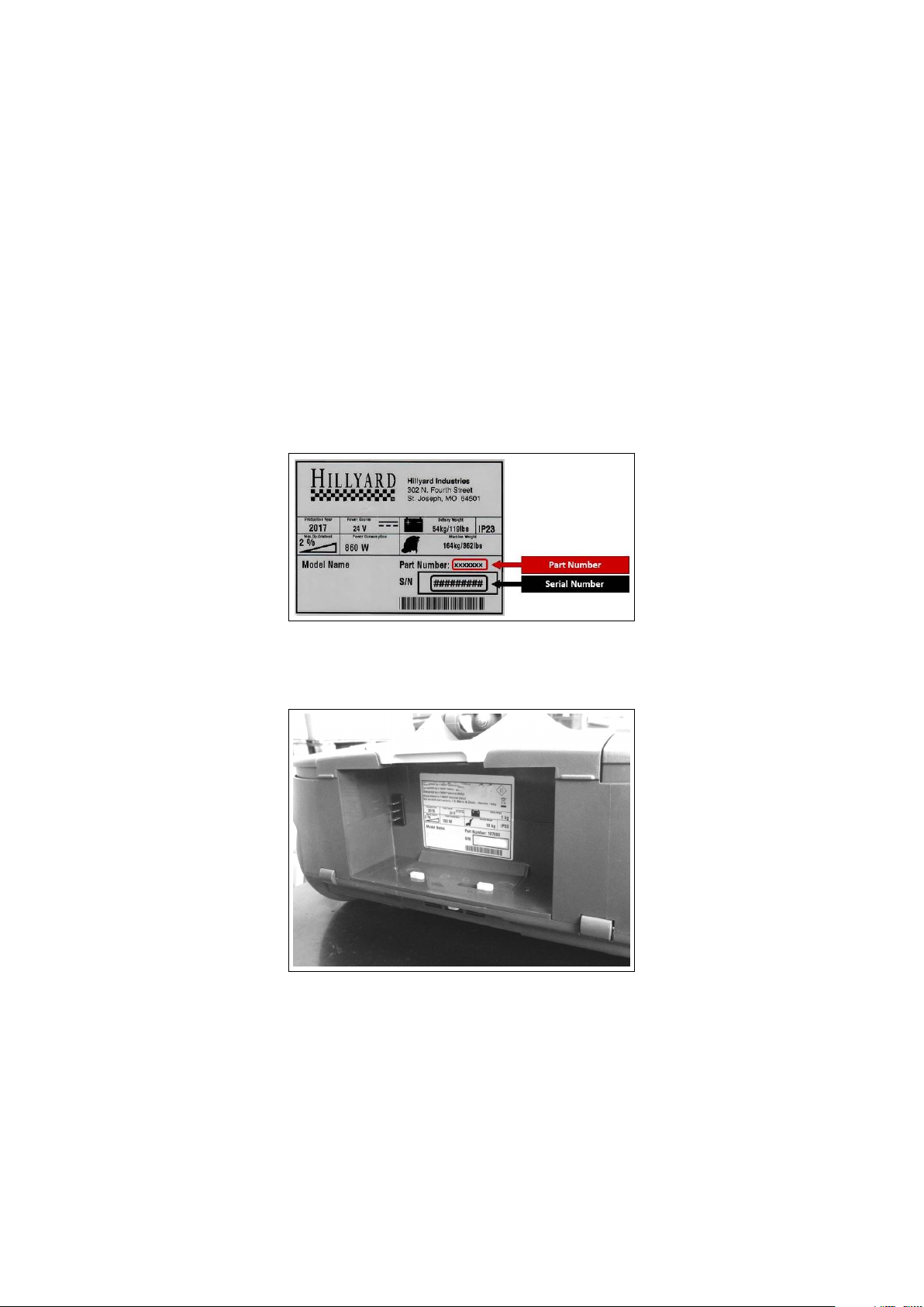
1.1 The Serial Tag
1.2 Serial Tag location
To have access to the Serial Tag it is sufficient to remove the battery.
The Serial Number is an extremely important information which has to be provided
each time a Technical Support is required or is necessary to buy spare parts or
accessories. The serial number is the only way to identify the machine by model,
production date type equipments in general.
5

Chapter 2
Main Technical Features
Technical Data
TECHNICAL DESCRIPTION U/M NM14
Working Width in 13,4
2
Working Capacity, up to
Brush Width/Revolutions φ in - rpm 13,4-375
Brush Motor Voltage/Power V-W 24-32
Max Weight on brush lb 10
Steering Diameter in 19,7
Maximum Ramp Gradient % 2
ft
h
7320
Total Power W 150
Squeegee Width in 15,4
Solution Tank gal 0,31
Recovery Tank gal 0,26
Vacuum Motor Stages/Depression Nr-mBar 1-45.1
Vacuum Motor Voltage/Power V-W 24-100
Machine Length (Handlebar Up - Down) in 17-36
Machine Height (Handlebar Up - Down) in 51-8,5
Machine Width in 15,5
Wheels (num/diam/width) Nr/φin/in 2/6/1
Wheel material/hardness TPV-85Sh
Sound pressure level (ISO 11201) LpA dB (A) ≤ 70
Hand vibration level (ISO 5349)
m
2
s
≤ 2.5
6

Weights and Pressures
1
TECHNICAL DESCRIPTION U/M NM14
Machine Weight (Machine + Brush + Squeegee) lb 20
Gross Weight of the machine in work conditions
(Machine + Battery+ Water + Brush + Squeegee)
lb 25
1
Weight and Pressures depends on how much water there is in the tanks.
7

Part II
Anomalies Resolution Guide
8

Chapter 3
Troubleshooting Guide
3.1 Basic Guide
3.1.1 Electrical system: what to do if. . .
The machine doesn’t switch on
1. The main switch is not pushed ⇒ Push the main switch.
2. The battery doesn’t work properly ⇒ Refer to the proper section (see section
3.1.1 at page 9).
3. You hear a click but the buttons
LEDs do not light up
⇒ Refer to the Advanced Guide (see section
3.2.2 at page 13).
The battery doesn’t work properly
1. The battery is not properly connected
2. The battery is discharged ⇒ Perform a complete charge cycle (see
3. The battery charger doesn’t work ⇒ Check the proper section (see section 3.1.1
4. The battery doesn’t work ⇒ Refer to the Advanced Guide (see section
⇒ Insert the battery until the end posi-
tion clicks.
section 5.3.5 at page 28).
at page 10).
3.2.4 at page 15).
9

The battery charger doesn’t work
1. The battery charger is not connected to the power supply
2. The battery charger has the Red
LED blinking
3. The battery charger plugged in and
turned on does not activate the
Green LED (power supply)
4. The battery charger plugged in and
turned on with battery inserted
does not activate the Red LED
(charging)
⇒ Connect the charger to a supplied
electric socket.
⇒ Unplug the charger from the wall
socket and from the battery, and reconnect them.
If the problem persists, replace the
battery charger.
⇒ Ensure the mains plug is properly in-
serted into the charger.
If the problem persists, replace the
battery charger.
⇒ Ensure that the charger plug is fully
inserted into battery.
The battery might be already
loaded.
Replace charger.
The machine has a very limited working autonomy
1. The battery has been working for
several cycles
2. The battery doesn’t work properly ⇒ Refer to the proper section (see section
⇒ Replace the battery.
3.1.1 at page 9).
10

3.1.2 Mechanical scrubbing system: what to do if. . .
The machine doesn’t clean well
1. The machine is switched off ⇒ Switch on the machine.
2. The machine doesn’t switch on ⇒ Refer to the proper section (see section
3.1.1 at page 9).
3. The handlebar rod is in the park po-
⇒ Tilt the handlebar rod.
sition
4. With tilted handlebar the machine
is not active
⇒ Refer to the Advanced Guide (see section
3.2.3 at page 14).
5. The brush motor doesn’t work ⇒ Refer to the Advanced Guide (see section
3.2.5 at page 15).
6. The brush is worn out ⇒ Replace the brush (see section 4.2 at page
20).
7. The detergent doesn’t fit the type of
dirt
8. The solution flow rate is not correct
or not enough
⇒ Replace the detergent with a proper
one.
⇒ Refer to the proper section (see section
3.1.3 at page 11).
3.1.3 Solution delivery system: what to do if. . .
The delivered solution is not correct or not enough
1. The machine is switched off ⇒ Switch on the machine.
2. The machine doesn’t switch on ⇒ Refer to the proper section (see section
3.1.1 at page 9).
3. The solution tank is empty ⇒ Fill up the solution tank.
4. The solution filter is missing or not
properly positioned
5. The solution filter is stuck ⇒ Clean the solution filter (see section 4.5 at
6. The water switch is not pushed ⇒ Push the water switch.
7. The water pump doesn’t work ⇒ Check the water pump connections
⇒ Restore the solution filter in the cor-
rect position (see section 4.5 at page 23).
page 23).
and, if necessary, replace it (see section
4.5 at page 23).
11

3.1.4 Drying system: what to do if. . .
The machine doesn’t dry well
1. The machine is switched off ⇒ Switch on the machine.
2. The machine doesn’t switch on ⇒ Refer to the proper section (see section
3.1.1 at page 9).
3. The vacuum motor doesn’t work ⇒ Refer to the Advanced Guide (see section
3.2.6 at page 16).
4. The recovery tank is full ⇒ Empty the recovery tank following
the proper procedure.
5. The squeegee is lifted up from the
floor
6. The squeegee rubber blades are
worn out or broken
7. The squeegee vacuum chamber or
the adapter is stuck or dirty
8. The vacuum hose is stuck or broken
9. The vacuum hose is not properly
fitted in
10. The air/water vacuum hoses body
is stuck or broken
11. The recovery tank lid or suction line
cover are not present or are not
properly positioned
12. The recovery tank does not guarantee the tightness of the aspiration
⇒ Lower down the squeegee.
⇒ Rotate or replace the squeegee rub-
ber blades (see section 7.3.1 at page 32).
⇒ Clean the squeegee.
⇒ Clean or replace the vacuum hose.
⇒ Connect the vacuum hose properly.
⇒ Clean or replace the vacuum hoses
body.
⇒ Correctly position the parts.
⇒ Replace the tank.
12
 Loading...