

Hillstone SG-6000-E5260, SG-6000-E5660, SG-6000-E3965, SG-6000-E5960, SG-6000-E3960 Hardware Reference Manual
...Page 1

Hillstone StoneOS User Manual
Hillstone Hardware Reference Guide
www.hillstonenet.com
Page 2
2
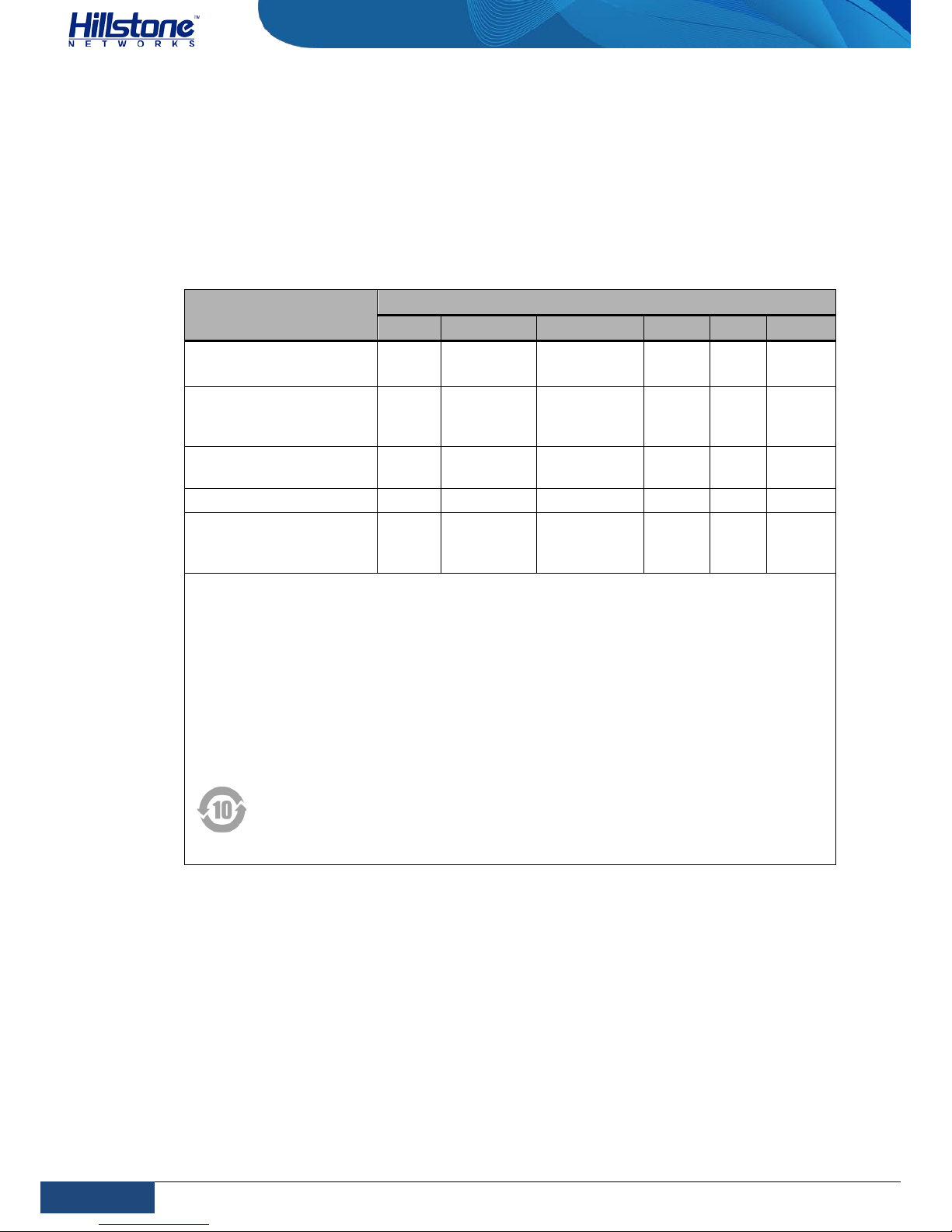
Name and Concentration of Toxic or Hazardous Substances and Elements in Products | Hillstone
Hillstone SG-6000 E-Series Hardware Reference Guide
Name and Concentration of Toxic or Hazardous
Substances and Elements in Products
Component
Toxic or hazardous substances and elements
Lead Mercury Cadmium Cr6+ PBB PDBE
Metal parts
(including fasteners)
Χ O O O O O
Printed circuit board
assemblies and
components
Χ O O O O O
Cables and cable
assemblies
Χ O O O O O
Plastics and Polymers Χ O O O Χ Χ
Electric components
other than circuit
boards
Χ O O O O O
O: Indicates that this toxic or hazardous substance in the material is below the limit
requirement defined in Requirements for Concentration Limits for Certain Hazardous
Substances in Electronic Information Products (SJ/T11363-2006) issued by Ministry
of Information Industry of PRC.
Χ: Indicates that this toxic or hazardous substance in the material exceeds the limit
requirement specified in Requirements for Concentration Limits for Certain Hazardous
Substances in Electronic Information Products (SJ/T11363-2006) issued by Ministry
of Information Industry of PRC.
Note: Not all components in the table are included in one product.
This symbol indicates the environment friendly use period of all products
and components. The period applies only to the normal operation conditions
specified in this guide.
Page 3

3
Preface | Hillstone
Hillstone SG-6000 E-Series Hardware Reference Guide
Preface
About This Guide
Thanks for choosing the network security products from Hillstone Networks, Inc.
This document is an installation guide for Hillstone devices to help you install the
Hillstone device properly.
This guide includes the following chapters:
♦ Chapter 1. Introduction
♦ Chapter 2. Installation Preparations
♦ Chapter 3. Installation
♦ Chapter 4. Boot and Configuration
♦ Chapter 5. Hardware Maintenance and Replacement
♦ Chapter 6. Troubleshooting
♦ Addendum FCC Statement
Document Conventions
This guide uses the following conventions for your convenience to read and
understand:
♦ Warning: Indicates improper operation that may cause serious damage to
equipment or injury to operators. Thus, operators must strictly follow the
operation rules.
♦ Caution: Indicates incorrect operation that may affect the normal use of the
equipment. Operators should be careful.
♦ Note: Indicates information that may help readers understand the content.
Page 4

4
Table of Contents | Hillstone
Hillstone SG-6000 E-Series Hardware Reference Guide
Table of Contents
CHAPTER 1 INTRODUCTION ........................................................................................................................................ 1
OVERVIEW ......................................................................................................................................................................... 1
HARDWARE OVERVIEW ......................................................................................................................................................... 1
Front Panel .................................................................................................................................................................. 1
Back Panel ................................................................................................................................................................... 8
LED Indicators ........................................................................................................................................................... 11
System Parameters ................................................................................................................................................... 13
Ports .......................................................................................................................................................................... 17
CLR Button ................................................................................................................................................................ 23
Expansion Slot ........................................................................................................................................................... 23
Power Supply ............................................................................................................................................................ 24
Expansion Modules ................................................................................................................................................... 26
CHAPTER 2 INSTALLATION PREPARATIONS ................................................................................................................27
INTRODUCTION ................................................................................................................................................................. 27
CLEANNESS REQUIREMENTS ................................................................................................................................................. 27
ESD PREVENTION .............................................................................................................................................................. 27
EMI PREVENTION .............................................................................................................................................................. 27
GROUNDING REQUIREMENTS ............................................................................................................................................... 28
WORKBENCH REQUIREMENTS .............................................................................................................................................. 28
OTHER SAFETY RECOMMENDATIONS ..................................................................................................................................... 28
UNPACKING ...................................................................................................................................................................... 28
INSTALLATION DEVICES/TOOLS/CABLES ................................................................................................................................. 28
CHAPTER 3 INSTALLATION .........................................................................................................................................30
BEFORE INSTALLATION ........................................................................................................................................................ 30
INSTALLING THE DEVICE ON A WORKBENCH ............................................................................................................................ 30
INSTALLING THE DEVICE ON A RACK ....................................................................................................................................... 31
CONNECTING CABLES ......................................................................................................................................................... 32
Connecting the Ground Wire .................................................................................................................................... 33
Connecting the Console Cable ................................................................................................................................... 33
Connecting the Ethernet Cable ................................................................................................................................. 33
Connecting an AC Power Cable ................................................................................................................................. 35
Connecting a DC Power Cable ................................................................................................................................... 36
Connecting a Power Adapter .................................................................................................................................... 37
INSTALLING AN ANTENNA .................................................................................................................................................... 37
INSTALLING THE SIM CARD .................................................................................................................................................. 38
VERIFYING INSTALLATION .................................................................................................................................................... 38
CHAPTER 4 BOOT AND CONFIGURATION ...................................................................................................................40
INTRODUCTION ................................................................................................................................................................. 40
ESTABLISHING A CONFIGURATION ENVIRONMENT .................................................................................................................... 40
Console (CON) Connection ........................................................................................................................................ 40
WebUI ....................................................................................................................................................................... 41
Page 5

5
Table of Contents | Hillstone
Hillstone SG-6000 E-Series Hardware Reference Guide
Tenet and SSH ........................................................................................................................................................... 42
BASIC CONFIGURATION ....................................................................................................................................................... 42
CHAPTER 5 HARDWARE MAINTENANCE AND REPLACEMENT ....................................................................................43
INTRODUCTION ................................................................................................................................................................. 43
INSTALLING AND REMOVING THE POWER SUPPLY MODULE ........................................................................................................ 43
INSTALLING AND REMOVING THE EXPANSION MODULE ............................................................................................................. 44
Installing and Removing the Fan Tray ...................................................................................................................... 44
Installing and Removing the Anti-dust Mesh ............................................................................................................ 45
CHAPTER 6 TROUBLESHOOTING ................................................................................................................................46
INTRODUCTION ................................................................................................................................................................. 46
LOSING THE ADMINISTRATOR PASSWORD ............................................................................................................................... 46
TROUBLESHOOTING POWER SYSTEM ..................................................................................................................................... 46
TROUBLESHOOTING THE CONFIGURATION SYSTEM ................................................................................................................... 46
ADDENDUM FCC STATEMENT ....................................................................................................................................47
COPYRIGHT INFORMATION ........................................................................................................................50
Page 6

6
List of Figures | Hillstone
Hillstone SG-6000 E-Series Hardware Reference Guide
List of Figures
Figure 1-1:SG-6000-E6360 Front Panel ..................................................................... 1
Figure 1-2: SG-6000-E6160 Front Panel ..................................................................... 2
Figure 1-3:SG-6000-E5960/E5760/E5660 Front Panel ................................................. 3
Figure 1-4: SG-6000-E5560/E5260/E3965 Front Panel ................................................. 3
Figure 1-5: Front Panel of SG-6000-E3960 .................................................................. 4
Figure 1-6: Front Panel of SG-6000-E3662/E3660/E2860 ............................................. 5
Figure 1-7: Front Panel of SG-6000-E2800 and SG-6000-E2300 .................................... 6
Figure 1-8: SG-6000-E1700/E1606 Front Panel ........................................................... 6
Figure 1-9: SG-6000-E1600 Front Panel ..................................................................... 7
Figure 1-10: Front Panel of SG-6000-E1100 (WLAN version) ......................................... 7
Figure 1-11: Front Panel of SG-6000-E1100 (WLAN+3G version) ................................... 8
Figure 1-12: SG-6000-E6360/E6160 Back Panel .......................................................... 8
Figure 1-13: SG-6000-E5960/E5760/E5660 Back Panel ................................................ 9
Figure 1-14: SG-6000-E5560/E5260/E3965 Back Panel ................................................ 9
Figure 1-15: Back Panel of SG-6000-
E3960/E3662/E3660/E2860/E2800/E2300/E1700/E1606 ........................................ 9
Figure 1-16: SG-6000-E1600 Back Panel .................................................................... 9
Figure 1-17: SG-6000-E1100 (WLAN version) Back Panel ........................................... 10
Figure 1-18: SG-6000-E1100 (WALN+3G version) Back Panel ..................................... 11
Figure 1-19: AC Power Module ................................................................................. 25
Figure 1-20: DC Power Module ................................................................................ 25
Figure 3-1: Installing the Rubber Pads ...................................................................... 30
Figure 3-2: Installing the Floating Nuts ..................................................................... 31
Figure 3-3: Installing the Rack-mounting Ears (1U Chassis as example) ....................... 32
Figure 3-4: Installing the Device in a Rack (1U Chassis as example) ............................ 32
Figure 3-5: Connecting the Ground Wire (1U Chassis as example) ............................... 33
Figure 3-6: Connecting the Ethernet Copper Cable ..................................................... 34
Figure 3-7: Connecting the Ethernet Fiber Cable ........................................................ 35
Figure 3-8: Connecting an AC Power Cable................................................................ 36
Figure 3-9: Connecting a DC Power Cable ................................................................. 37
Figure 3-10: 3G Antenna and WLAN Antenna ............................................................ 37
Figure 3-11: Antenna Installation Illustration ............................................................ 38
Figure 4-1: Console Port Configuration ..................................................................... 40
Figure 4-2: Setting Parameters for the Terminal Session ............................................ 41
Figure 5-1: Installing Power Supply Module ............................................................... 43
Figure 5-2: Pulling Anti-dust Mesh Out ..................................................................... 45
Page 7

7
List of Tables | Hillstone
Hillstone SG-6000 E-Series Hardware Reference Guide
List of Tables
Table 1-1: SG-6000-E6360 Front Panel Description .................................................................................................... 2
Table 1-2: SG-6000-E6160 Front Panel Description .................................................................................................... 2
Table 1-3: SG-6000-E5960/E5760/E5660 Front Panel Description ............................................................................. 3
Table 1-4: SG-6000-E5560/E5260/E3965 Front Panel Description ............................................................................. 4
Table 1-5: SG-6000-E3960 Front Panel Description .................................................................................................... 5
Table 1-6: SG-6000-E3662/E3660/E2860 Front Panel Description ............................................................................. 5
Table 1-7: Front Panel Description of SG-6000-E2800 and SG-6000-E2300 ............................................................... 6
Table 1-8: SG-6000-E1700/E1606 Front Panel Description......................................................................................... 6
Table 1-9: SG-6000-E1600 Front Panel Description .................................................................................................... 7
Table 1-10: Front Panel Description of SG-6000-E1100 (WLAN version) .................................................................... 7
Table 1-11: Front Panel Description of SG-6000-E1100 (WLAN+3G version) .............................................................. 8
Table 1-12: Back Panel Description of SG-6000-E1600 ............................................................................................. 10
Table 1-13: Back Panel Description of SG-6000-E1100 (WLAN version) ................................................................... 10
Table 1-14: Back Panel Description of SG-6000-E1100 (WLAN+3G version)............................................................. 11
Table 1-15: Front Panel LED Descriptions ................................................................................................................. 11
Table 1-16: System Parameters ................................................................................................................................ 13
Table 1-17: Console Port Attributes .......................................................................................................................... 17
Table 1-18: Auxiliary Port Attributes ......................................................................................................................... 18
Table 1-19: USB Port Attributes ................................................................................................................................ 18
Table 1-20: Gigabit Copper Port Attributes .............................................................................................................. 18
Table 1-21: SFP Port Attributes ................................................................................................................................. 19
Table 1-22: SFP Optical Module Attributes ............................................................................................................... 19
Table 1-23: SFP Copper Module Attributes ............................................................................................................... 20
Table 1-24: SFP+ Port Attributes ............................................................................................................................... 20
Table 1-25: SFP+ Optical Module Attributes ............................................................................................................. 21
Table 1-26: QSFP+ Port Attributes ............................................................................................................................ 21
Table 1-27: QSFP+ Optical Module Attributes .......................................................................................................... 22
Table 1-28: XFP Port Attributes ................................................................................................................................. 22
Table 1-29: XFP Optical Module Attributes ............................................................................................................... 22
Table 1-30: Power Supplies of All Product Models .................................................................................................... 24
Table 1-31: Power Supply Module LED Descriptions ................................................................................................. 26
Table 2-1: Dust Concentration Requirements in the Equipment Room .................................................................... 27
Page 8
1
Chapter 1 Introduction | Hillstone
Hillstone SG-6000 E-Series Hardware Reference Guide
Chapter 1 Introduction
Overview
Hillstone SG-6000 series product models include SG-6000-E6360, SG-6000-E6160,
SG-6000-E5960, SG-6000-E5760, SG-6000-E5660, SG-6000-E5560, SG-6000E5260, SG-6000-E3965, SG-6000-E3960, SG-6000-E3662, SG-6000-E3660, SG6000-E2860, SG-6000-E2800, SG-6000-E2300, SG-6000-E1700, SG-6000-E1606,
SG-6000-E1600, SG-6000-E1100 (WLAN version), and SG-6000-E1100 (WLAN+3G
version).
SG-6000-E6360, SG-6000-E6160, SG-6000-E5960, SG-6000-E5760, SG-6000E5660, SG-6000-E5560, SG-6000-E5260, SG-6000-E3965, SG-6000-E3960, SG6000-E3662, SG-6000-E3660 and SG-6000-E2860 adopt modular design of hotswappable circuit boards. For more information about extensible modules, please
see Hillstone SG-6000 M_G_E Series Expansion Modules Reference Guide.
Hardware Overview
Hillstone devices are designed to fit in standard 19-inch cabinets/racks. A device
can be installed in a cabinet/rack or placed on a workbench.
Front Panel
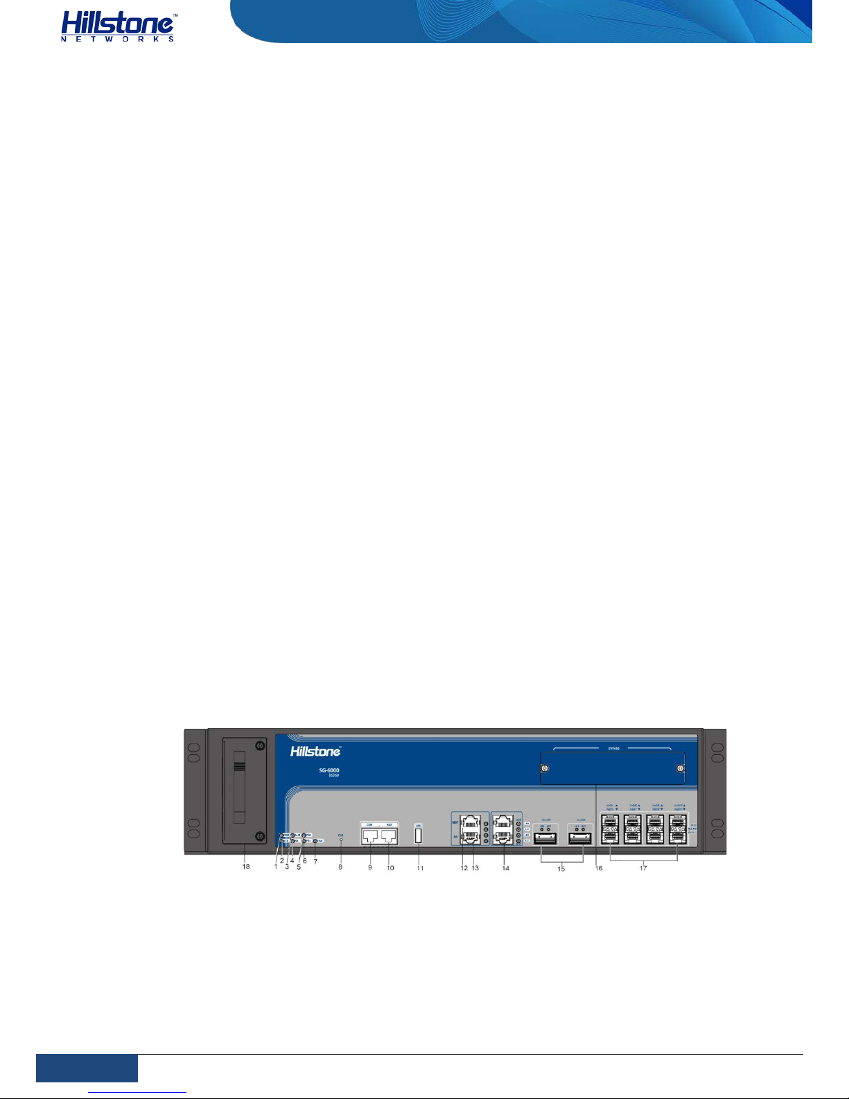
The front panel of SG-6000-E6360 consists of 2 Gigabit Ethernet ports, 8 SFP+
ports, 2 QSFP+ports, 1 USB port, 1 HA port, 1 Management port, 1 Console port, 1
Auxiliary port, 1 CLR button, 1 Bypass expansion slot and several LED indicators.
Figure 1-1:SG-6000-E6360 Front Panel
Page 9
2
Chapter 1 Introduction | Hillstone
Hillstone SG-6000 E-Series Hardware Reference Guide
Table 1-1: SG-6000-E6360 Front Panel Description
No. Label No. Label No. Label
1 PWR: Power LED 7 FAN: Fan LED 13 HA: HA port
2 STA: Status LED 8 CLR: CLR button 14
e0/0 - e0/1: Gigabit
Ethernet ports
3 ALM: Alarm LED 9 CON: Console port 15
XLe0/2-XLe0/3: QSFP+
ports
4
HA: HA status
LED
10
AUX: Auxiliary
port
16 Bypass expansion slot
5
PS0: Power
supply PS0 LED
11 USB: USB port 17
Xe0/4-Xe0/11: SFP+
ports
6
PS1: Power
supply PS1 LED
12
MGT:
Management port
18 Fan tray
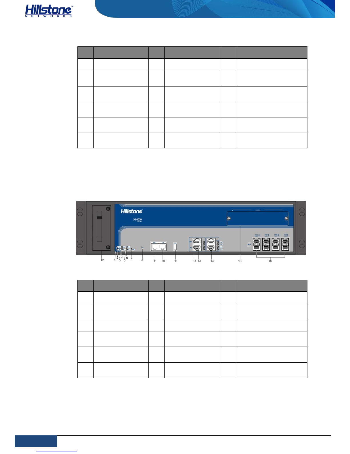
The front panel of SG-6000-E6160 consists of 2 Gigabit Ethernet ports, 8 SFP+
ports, 1 USB port, 1 HA port, 1 Management port, 1 Console port, 1 Auxiliary port,
1 CLR button, 1 Bypass expansion slot and several LED indicators.
Figure 1-2: SG-6000-E6160 Front Panel
Table 1-2: SG-6000-E6160 Front Panel Description
No. Label No. Label No. Label
1 PWR: Power LED 7 FAN: Fan LED 13 HA: HA port
2 STA: Status LED 8 CLR: CLR button 14
e0/0 - e0/1: Gigabit
Ethernet ports
3 ALM: Alarm LED 9 CON: Console port 15 Bypass expansion slot
4
HA: HA status
LED
10
AUX: Auxiliary
port
16
Xe0/2-Xe0/9: SFP+
ports
5
PS0: Power
supply PS0 LED
11 USB: USB port 17 Fan tray
6
PS1: Power
supply PS1 LED
12
MGT:
Management port
18
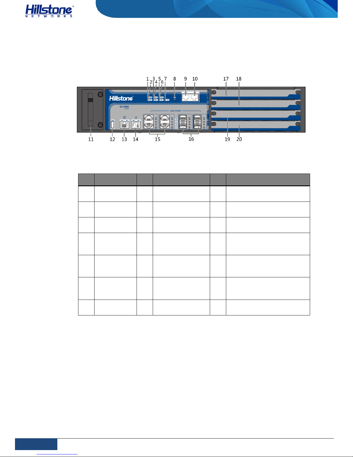
SG-6000-E5960, SG-6000-E5760, and SG-600-E5660 have the same front panel.
The front panel consist of 4 Gigabit Ethernet ports, 4 SFP ports, 1 USB port, 1 HA
port, 1 Management port, 1 Console port, 1 Auxiliary port, 1 CLR button, 4 general
Page 10
3
Chapter 1 Introduction | Hillstone
Hillstone SG-6000 E-Series Hardware Reference Guide
expansion slots and several LED indicators. The standard power supply for SG6000-E5960/E5760 is dual power supplies, and the product with single power
supply is also available.
Figure 1-3:SG-6000-E5960/E5760/E5660 Front Panel
Table 1-3: SG-6000-E5960/E5760/E5660 Front Panel Description
No. Label No. Label No. Label
1
PWR: Power
LED
8 CLR: CLR button 15
e0/2 - e0/5: Gigabit
Ethernet ports
2
STA: Status
LED
9 CON: Console port 16 e0/6 - e0/9: SFP ports
3
ALM: Alarm
LED
10
AUX: Auxiliary
port
17
Slot 1: General expansion
slot
4
HA: HA
status LED
11 Fan tray 18
Slot 2: General expansion
slot (not for storage
expansion module)
5
PS0: Power
supply PS0
LED
12 USB: USB port 19
Slot 3: General expansion
slot (not for storage
expansion module)
6
PS1: Power
supply PS1
LED
13
MGT (e0/0):
Management port
20
Slot 4: General expansion
slot (not for storage
expansion module)
7
FAN: Fan
LED
14
HA (e0/1): HA
port
- -
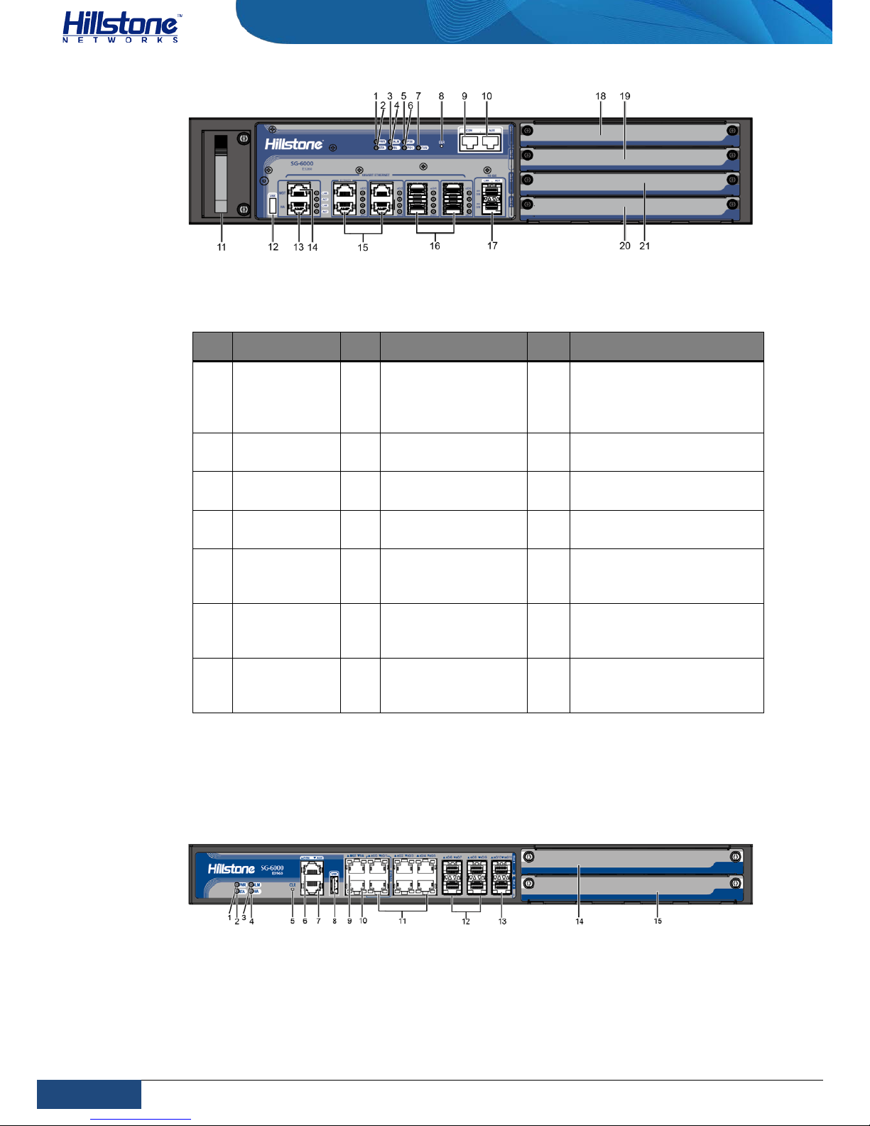
SG-6000-E5560, SG-6000-E5260 and SG-6000-E3965 have the same front panel.
The front panel consists of 4 Gigabit Ethernet por ts, 4 S FP por ts, 2 SFP+ ports, 1
USB port, 1 Console port, 1 Auxiliary port, 1 Management port, 1 HA port, 1 CLR
button, 4 general expansion slots, 1 fan tray, and some LED indicators.
Figure 1-4: SG-6000-E5560/E5260/E3965 Front Panel
Page 11
4
Chapter 1 Introduction | Hillstone
Hillstone SG-6000 E-Series Hardware Reference Guide
Table 1-4: SG-6000-E5560/E5260/E3965 Front Panel Description
No. Label No. Label No. Label
1
PWR: Power
LED
8 CLR: CLR button 15
e0/ - e0/3: Gigabit
Ethernet ports (e0/2 and
e0/3 support the Bypass
function)
2
STA: Status
LED
9 CON: Console port 16 e0/4 - e0/7: SFP ports
3
ALM: Alarm
LED
10 AUX: Auxiliary port 17 xe08 - xe09: SFP+ ports
4
HA: HA
status LED
11 Fan tray 18
Slot 1: General expansion
slot
5
PS0: Power
supply PS0
LED
12 USB: USB port 19
Slot 2: General expansion
slot (not for storage
expansion module)
6
PS1: Power
supply PS1
LED
13 HA: HA port 20
Slot 3: General expansion
slot (not for storage
expansion module)
7 FAN: Fan LED 14
MGT: Management
port
21
Slot 4: General expansion
slot (not for storage
expansion module)
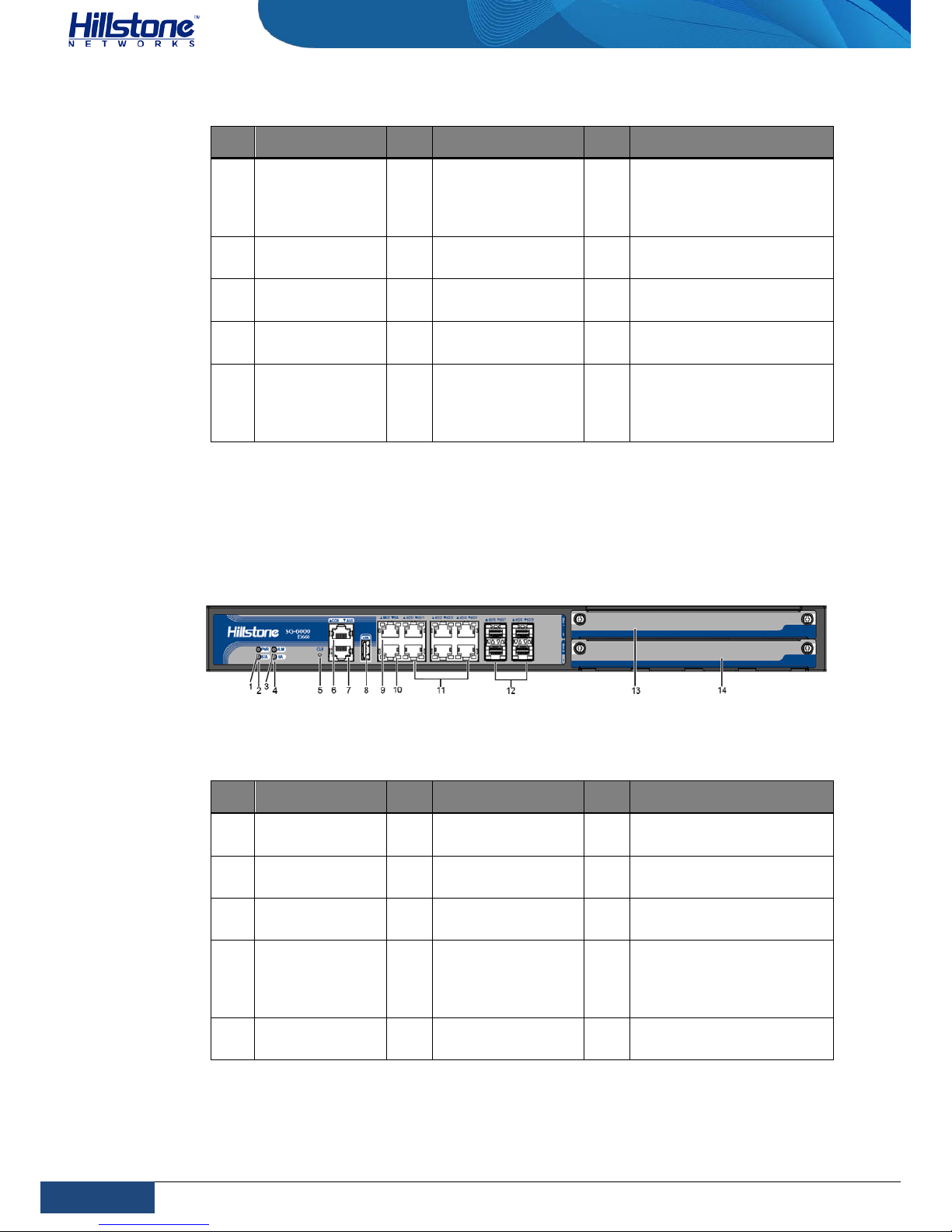
The front panel of SG-6000-E3960 consists of 6 Gigabit Ethernet ports, 4 SFP ports,
2 SFP+ ports, 1 USB port, 1 Console port, 1 Auxiliary port, 1 Management port, 1
HA port, 1 CLR button, 2 general expansion slots and several LED indicators.
Figure 1-5: Front Panel of SG-6000-E3960
Page 12
5
Chapter 1 Introduction | Hillstone
Hillstone SG-6000 E-Series Hardware Reference Guide
Table 1-5: SG-6000-E3960 Front Panel Description
No. Label No. Label No. Label
1
PWR: Power
LED
6
CON: Console
port
11
e0/0 - e0/5: Gigabit
Ethernet ports (e0/0 and
e0/1 supports the
Bypass function)
2
STA: Status
LED
7
AUX: Auxiliary
port
12 e0/6 - e0/9: SFP ports
3
ALM: Alarm
LED
8 USB: USB port 13
xe0/10 – xe0/11: SFP+
ports
4
HA:HA status
LED
9
MGT:
Management port
14
Slot 1: General
expansion slot
5
CLR: CLR
button
10 HA: HA port 15
Slot 2: General
expansion slot (not for
storage expansion
module)
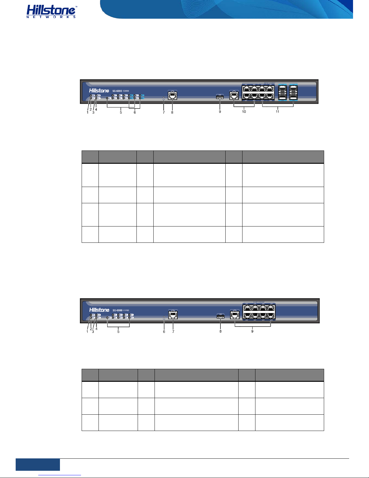
SG-6000-E3662, SG-6000-E3660 and SG-6000-E2860 have the same front
panel.The front panel consists of 6 Gigabit Ethernet ports, 4 SFP ports, 1 USB port,
1 Console port, 1 Auxiliary port, 1 Management port, 1 HA port, 1 CLR button, 2
general expansion slots and several LED indicators.
Figure 1-6: Front Panel of SG-6000-E3662/E3660/E2860
Table 1-6: SG-6000-E3662/E3660/E2860 Front Panel Description
No. Label No. Label No. Label
1
PWR: Power
LED
6
CON: Console
port
11
e0/0 - e0/5: Gigabit
Ethernet ports
2
STA: Status
LED
7
AUX: Auxiliary
port
12 e0/6 - e0/9: SFP ports
3
ALM: Alarm
LED
8 USB: USB port 13
Slot 1: General
expansion slot
4
HA:HA status
LED
9
MGT:
Management port
14
Slot 2: General
expansion slot (not for
storage expansion
module)
5
CLR: CLR
button
10 HA: HA port - -
Page 13
6
Chapter 1 Introduction | Hillstone
Hillstone SG-6000 E-Series Hardware Reference Guide
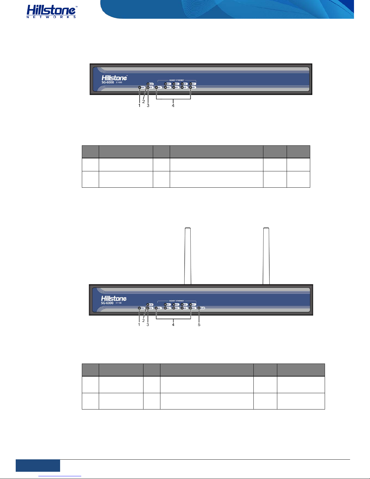
SG-6000-E2800 and SG-6000-E2300 have the same front panel. The fro n t panel
consists of 5 Gigabit Ethernet ports, 4 Combo ports (Ethernet port + SFP port), 1
USB port, 1 Console port, 1 CLR button and some LED indicators.
Figure 1-7: Front Panel of SG-6000-E2800 and SG-6000-E2300
Table 1-7: Front Panel Description of SG-6000-E2800 and SG-6000-E2300
No. Label No. Label No. Label
1
PWR:
Power LED
5
e0/0 - e0/8: Gigabit
Ethernet port status
LED
9 USB: USB port
2
STA:
Status LED
6
e0/5 - e0/8: SFP
interface LED
10
e0/0 - e0/4: Gigabit
Ethernet ports
3
ALM:
Alarm LED
7 CLR: CLR button 11
e0/0 - e0/4: Combo ports
(Ethernet port + SFP
port)
4
HA: HA
status LED
8 CON: Console port - -
SG-6000-E1700 and SG-6000-E1606 have the same front panel. The front panel
consists of 9 Gigabit Ethernet ports, 1 USB port, 1 Console port, 1 CLR button and
some LED indicators.
Figure 1-8: SG-6000-E1700/E1606 Front Panel
Table 1-8: SG-6000-E1700/E1606 Front Panel Description
No. Label No. Label No. Label
1
PWR:
Power LED
4 HA: HA status LED 7 CON: Console port
2
STA:
Status LED
5
e0/0 - e0/4: Gigabit
Ethernet port status LED
8 USB: USB port
3
ALM: Alarm
LED
6 CLR: CLR button 9
e0/0 - e0/4: Gigabit
Ethernet ports
Page 14
7
Chapter 1 Introduction | Hillstone
Hillstone SG-6000 E-Series Hardware Reference Guide
The front panel of SG-6000-E1600 consists of some LED indicators.
Figure 1-9: SG-6000-E1600 Front Panel
Table 1-9: SG-6000-E1600 Front Panel Description
No. Label No. Label No. Label
1 PWR: Power LED 3 STA: Status LED - -
2 ALM: Alarm LED 4
e0/0 - e0/8: Gigabit Ethernet
port status LED
- -
The front panel of SG-6000-E1100 (WLAN version) consists of some LED indicators.
Figure 1-10: Front Panel of SG-6000-E1100 (WLAN version)
Table 1-10: Front Panel Description of SG-6000-E1100 (WLAN version)
No. Label No. Label No. Label
1
PWR: Power
LED
3 STA: Status LED 5
WLAN: WLAN
LED
2
ALM: Alarm
LED
4
e0/0 - e0/8: Gigabit Ethernet
port status LED
- -
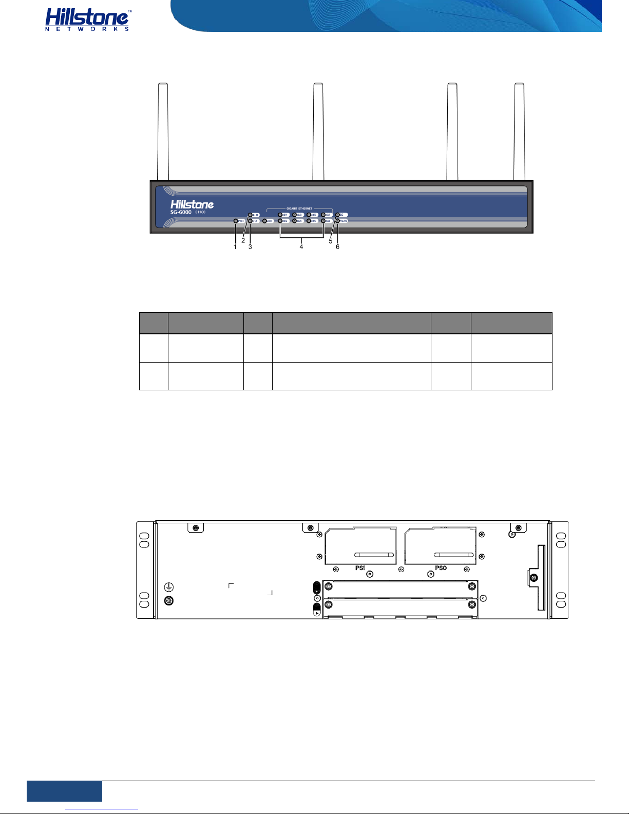
The front panel of SG-6000-E1100 (WLAN+3G version) consists of some LED
indicators.
Page 15
8
Chapter 1 Introduction | Hillstone
Hillstone SG-6000 E-Series Hardware Reference Guide
Figure 1-11: Front Panel of SG-6000-E1100 (WLAN+3G version)
Table 1-11: Front Panel Description of SG-6000-E1100 (WLAN+3G version)
No. Label No. Label No. Label
1
PWR: Power
LED
3 STA: Status LED 5 3G: 3G LED
2
ALM: Alarm
LED
4
e0/0 - e0/8: Gigabit Ethernet
port status LED
6
WLAN: WLAN
LED
Back Panel
SG-6000-E6360 and SG-6000-E6160 have the same back panel layout. The back
panel layout of SG-6000-E6360/E6160 consists of 2 power supply sockets, 2
expansion slots, 1 grounding screw and 1 anti-dust mesh.
Figure 1-12: SG-6000-E6360/E6160 Back Panel
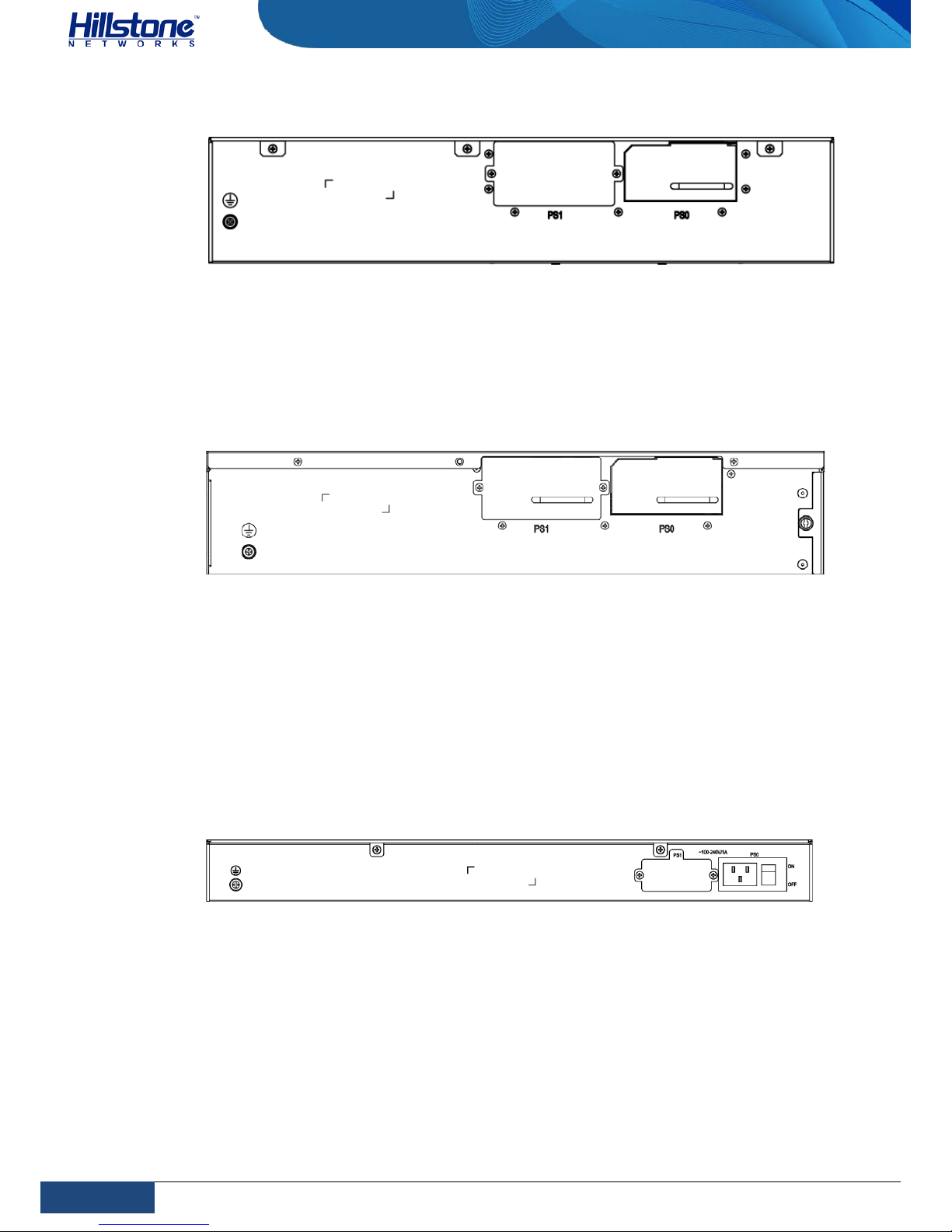
SG-6000-E5960 ,SG-6000-E5760 and SG-6000-E5660 have the same back panel
layout. The back panel layout of SG-6000-E5960/E5760/E5660 consists of 2 power
supply sockets, 1 grounding screw. The standard product of SG-6000E5960/E5760/E5660 adopts dual power supplies and it is also available in single
power supply.
Page 16
9
Chapter 1 Introduction | Hillstone
Hillstone SG-6000 E-Series Hardware Reference Guide
Figure 1-13: SG-6000-E5960/E5760/E5660 Back Panel
SG-6000-E5560 SG-6000-E5260 and SG-6000-E3965 have the same back panel
The back panel consists of 2 power supply sockets, 1 grounding screw and 1 antidust mesh. The standard product of SG-6000-E5560/E5260/E3965 adopts dual
power supplies and it is also available in single power supply.
Figure 1-14: SG-6000-E5560/E5260/E3965 Back Panel
SG-6000-E3960, SG-6000-E3662, SG-6000-E3660, SG-6000-E2860, SG-6000E2800, SG-6000-E2300, SG-6000-E1700 and SG-6000-E1606 have the same back
panel layout. The standard products SG-6000-E2800, SG-6000-E2300, SG-6000E1700 and SG-6000-E1606 adopt single power supply and they are also available in
dual power supplies. The back panel of single power supply product has 1 power
supply socket, 1 power supply switch and 1 grounding screw. Figure 1-13 illustrates
the back panel of these models.
Figure 1-15: Back Panel of SG-6000E3960/E3662/E3660/E2860/E2800/E2300/E1700/E1606
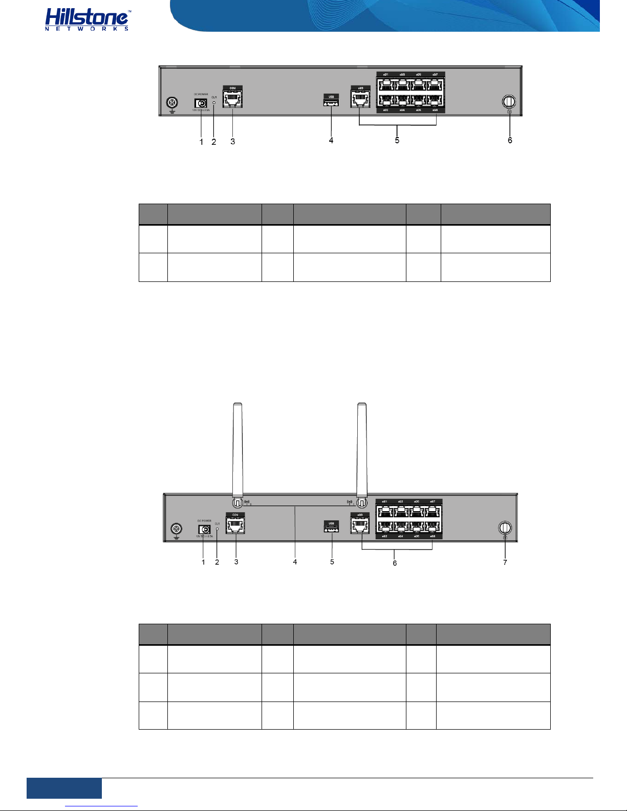
SG-6000-E1600 uses the power adapter. The back panel of SG-6000-E1600 has 1
power supply socket, 1 Console port, 1 CLR button, 9 Gigabyte Ethernet ports, 1
USB port, 1 grounding screw, and 1 security keyhole.
Figure 1-16: SG-6000-E1600 Back Panel
Page 17
10
Chapter 1 Introduction | Hillstone
Hillstone SG-6000 E-Series Hardware Reference Guide
Table 1-12: Back Panel Description of SG-6000-E1600
No. Label No. Label No. Label
1
DC POWER: DC
power interface
3 CON: Console port 5
e0/0 - e0/8: Gigabit
Ethernet port
2
CLR: CLR
button
4 USB: USB port 6 Security keyhole
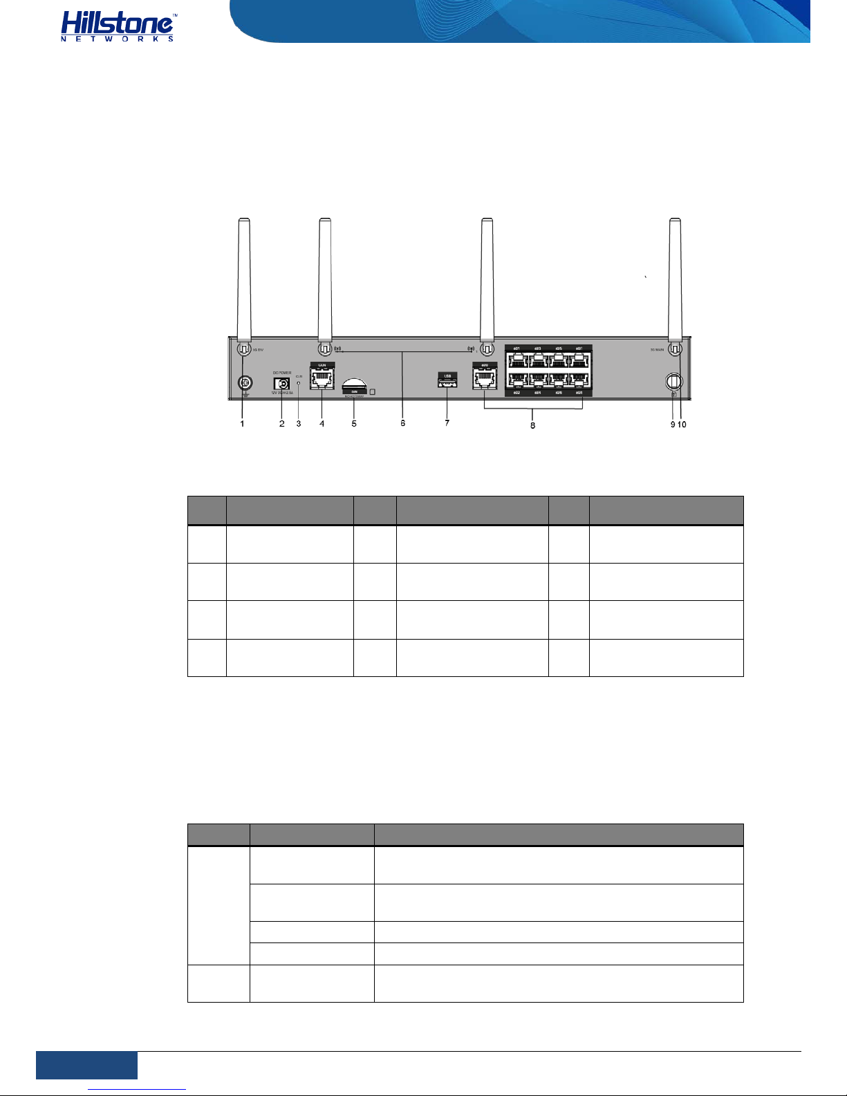
SG-6000-E1100 (WLAN version) uses the power adapter. The back panel of SG6000-E1100 (WLAN version) has 1 power supply socket, 1 Console port, 1 CLR
button, 9 Gigabyte Ethernet ports, 1 USB port, 1 grounding screw, 1 security
keyhole, and 2 SMA connectors for WLAN antennas. Figure 1-15 illustrates the back
panel of this model.
Figure 1-17: SG-6000-E1100 (WLAN version) Back Panel
Table 1-13: Back Panel Description of SG-6000-E1100 (WLAN version)
No. Label No. Label No. Label
1
DC POWER: DC
power interface
4
SMA connectors for
WLAN antennas
7 Security keyhole
2
CLR: CLR
button
5 USB: USB port - -
3
CON: Console
port
6
e0/0 - e0/8: Gigabit
Ethernet port
- -
Page 18
11
Chapter 1 Introduction | Hillstone
Hillstone SG-6000 E-Series Hardware Reference Guide
SG-6000-E1100 (WLAN+3G version) uses the power adapter. The back panel of
SG-6000-E1100 (WLAN+3G version) has 1 power supply socket, 1 Console port, 1
CLR button, 9 Gigabyte Ethernet ports, 1 USB port, 1 grounding screw, 1 security
keyhole, 2 SMA connectors for 3G antennas, and 2 SMA connectors for WLAN
antennas.
Figure 1-18: SG-6000-E1100 (WALN+3G version) Back Panel
Table 1-14: Back Panel Description of SG-6000-E1100 (WLAN+3G version)
No. Label No. Label No. Label
1
SMA connector
for 3G antenna
5 SIM: SIM card slot 9 Security keyhole
2
DC POWER: DC
power interface
6
SMA connectors for
WLAN antennas
10
SMA connector for
3G antenna
3
CLR: CLR
button
7 USB: USB port - -
4
CON: Console
port
8
e0/0 - e0/8: Gigabit
Ethernet port
- -
LED Indicators
The following table describes the meanings of LED indicators on the front panels of
Hillstone devices.
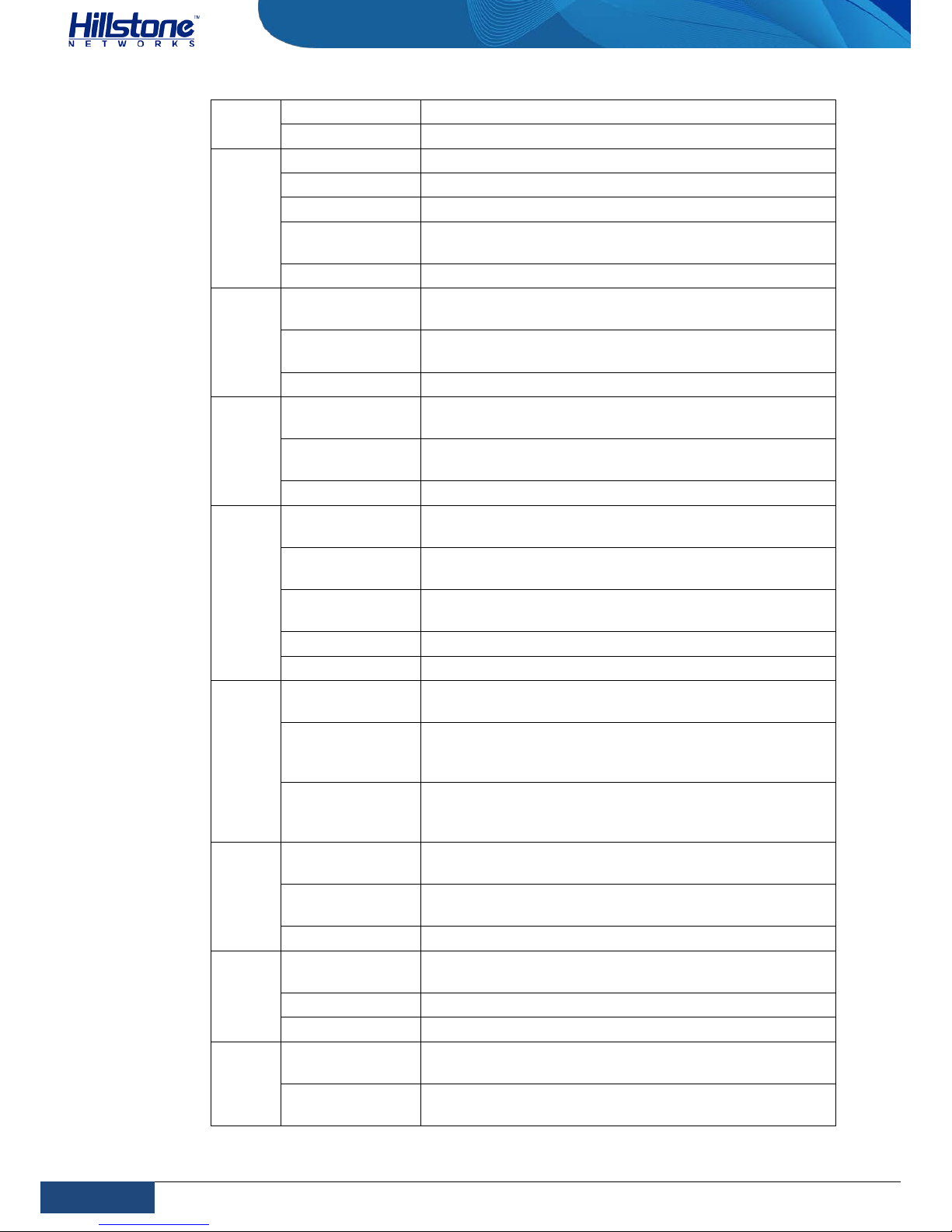
Table 1-15: Front Panel LED Descriptions
LED Color/Status Description
PWR
Green/Always
on
The device power is running normally.
Orange/Always
on
The device power is running abnormally.
Red/Always on Power failure so the system is down.
Off The device is powered off.
STA
Green/Always
on
The system is booting.
Page 19
12
Chapter 1 Introduction | Hillstone
Hillstone SG-6000 E-Series Hardware Reference Guide
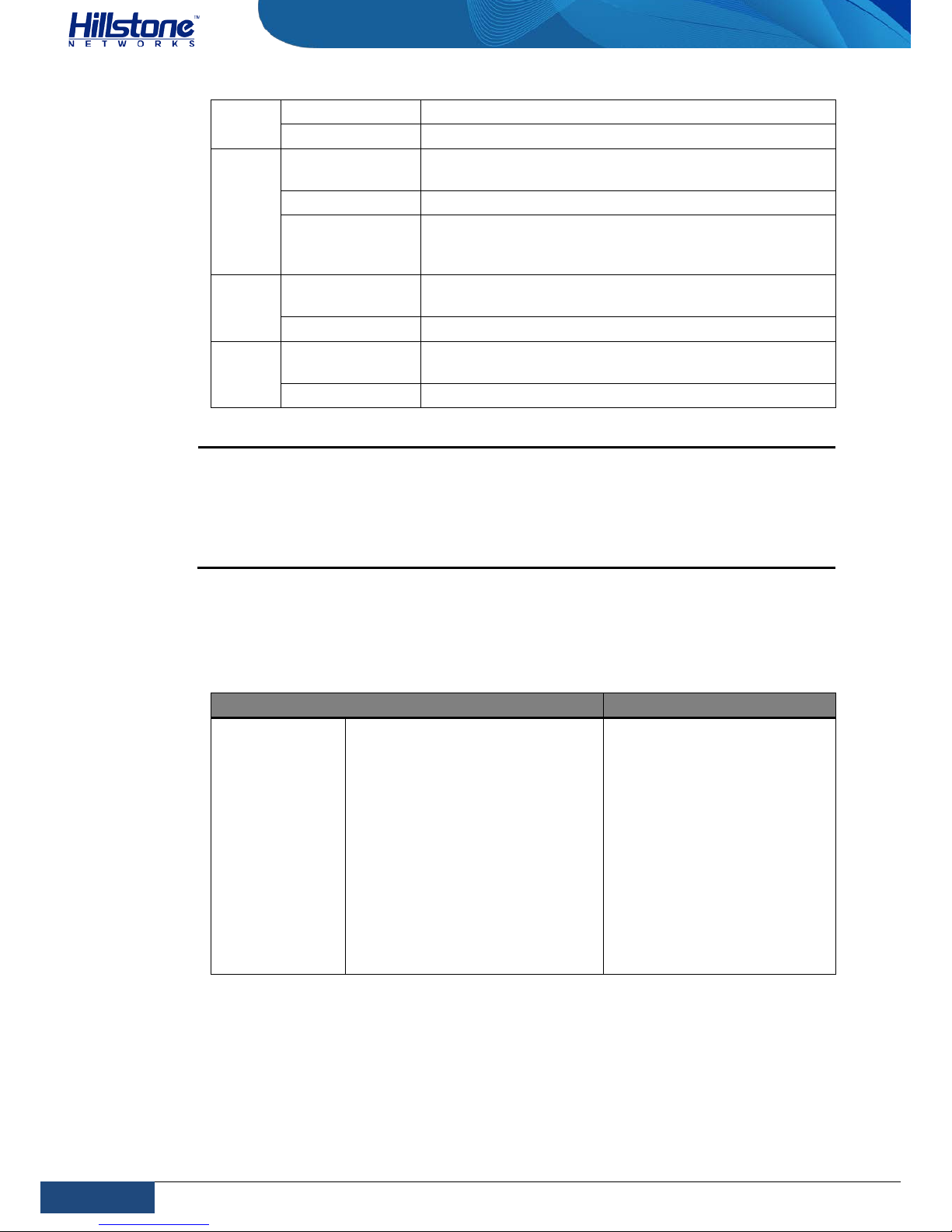
Green/Blinking The system is running normally.
Red/Always on The system has failed to boot or has an error.
ALM
Red/Always on The system is sending alarm(s).
Green/Blinking The system is waitin g.
Orange/Blinking The system is using a trial license.
Orange/Always
on
The trial license has expired and there is no
legitimate license installed in the system.
Off The system is running normally.
PS0
Green/Always
on
Power Supply PS0 is running normally.
Orange/Always
on
Power Suppl y PS0 is runni ng normally, but its fan has
failed. Change the power supply immediately.
Off Power Supply PS0 is powered off or has failed.
PS1
Green/Always
on
Power Supply PS1 is running normally.
Orange/Always
on
Power Supply PS1 is running normally, but its fan has
failed. Change the power supply immediately.
Off Power Supply PS0 is powered off or has failed.
HA
Green/Always
on
Not using HA, this device is the master device.
Green/Blinking
Two devices are in an HA cluster. This device is
working as the master.
Orange/Blinking
Two devices are in an HA cluster. This device is
working as the slave.
Red/Blinking HA function has failed.
Off High Availability is disabled.
FAN
Green/Always
on
The cooling system is running normally.
Orange/Always
on
One of the fans has failed, but the cooling system can
still fully function. Change the fan tray as soon as
possible.
Red/Always on
The coolin g syst em has a serious error or the fan tray
is not fully inserted. The system will automatically
shut down in 15 seconds.
VPN
Green/Always
on
The VPN tunnel is connected.
Orange/Always
on
VPN is turned on but no tunnel is connected.
Off VPN is not in use.
SD
Green/Always
on
SD card has been inserted and is in normal status.
Green/Blinking SD card is transmitting data.
Off No SD card is inserted.
LNK
Green/Always
on
The link between this port and its peer device is in
normal status.
Off
The link between this port and its peer device has
failed.
Page 20
13
Chapter 1 Introduction | Hillstone
Hillstone SG-6000 E-Series Hardware Reference Guide
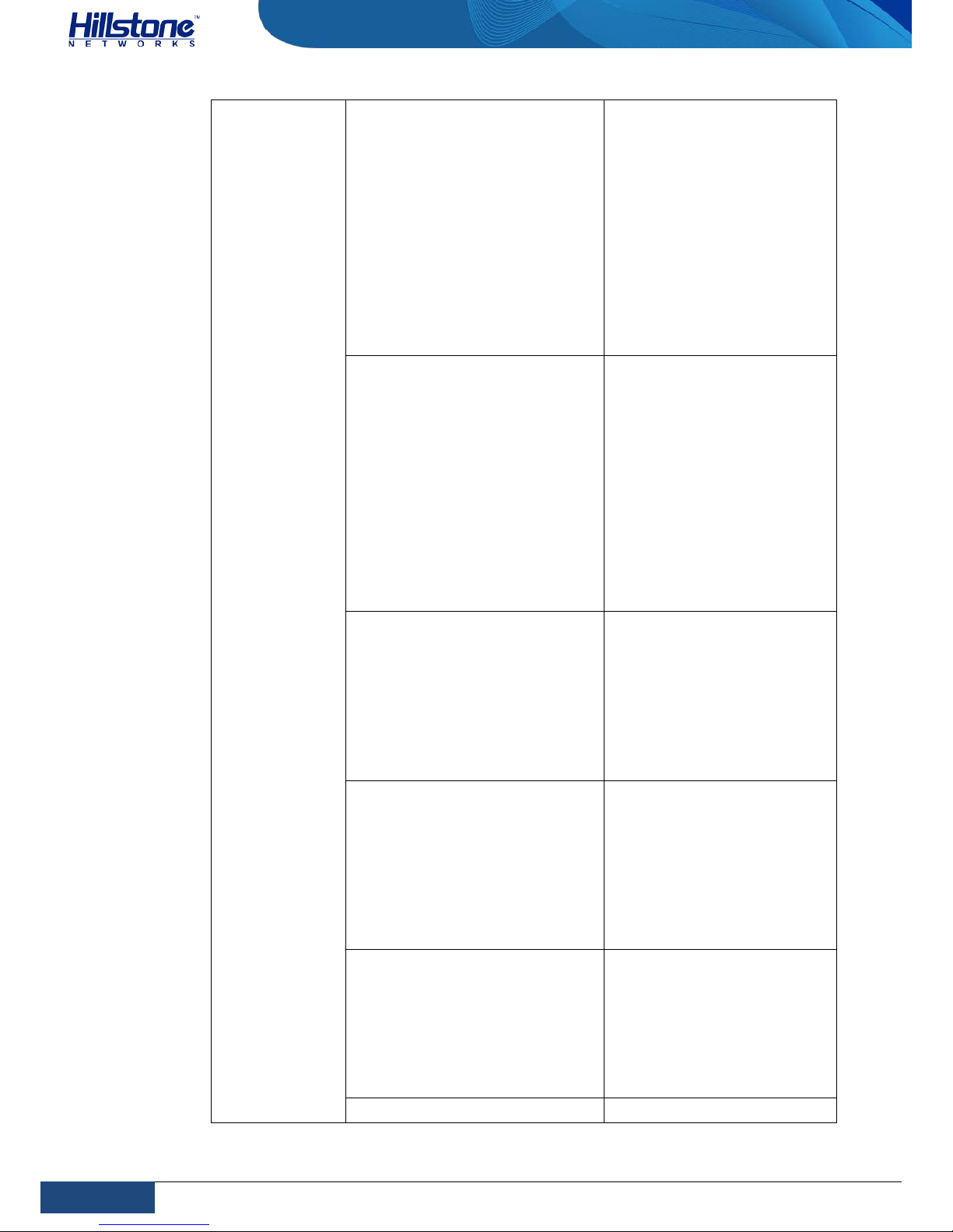
ACT
Orange/Blinking The port is sending or receiving data.
Off No data is transmitted on this port.
e0/0e0/8
Green/Always
on
The link between this port and its peer device is in
normal status.
Green/Blinking The port is sending or receiving data.
Off
There is no connection between this port with the its
peer device, o r t he link between this port and its peer
device fails.
3G
Green/Always
on
The device discovers the built-in 3G Express module.
Green/Blinking The 3G module is sending or receiving data.
WLAN
Green/Always
on
The device discovers the built-in WLAN module.
Green/Blinking The WLAN module is sending or receiving data.
Notes:
♦ The STA and ALM LEDs will both turn red when there is a boot failure
caused by OS software damage. Contact your sales representative if this
occurs.
♦ As the number and type of LED indicato rs may vary from different product
models, please refer to the actual product.
System Parameters
The following table lists the system parameters of Hillstone devices of all models.
Table 1-16: System Parameters
Item Description
Fixed Ports
SG-6000-E6360
2 Gigabit Ethernet ports
8 SFP+ ports
2 QSFP+ ports
1 USB 2.0 Host port
1 MGT port
1 HA port
1 Console port
1 Auxiliary port
Page 21
14
Chapter 1 Introduction | Hillstone
Hillstone SG-6000 E-Series Hardware Reference Guide
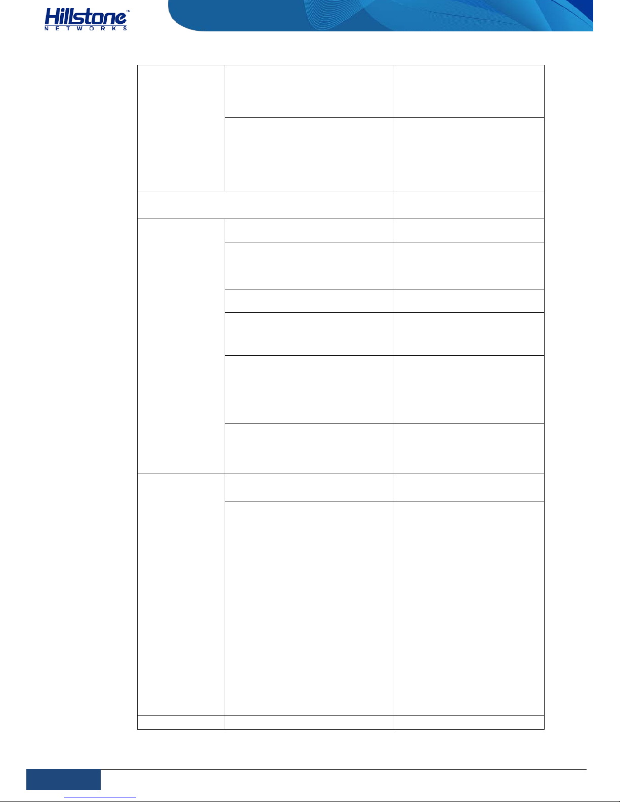
SG-6000-E6160
2 Gigabit Ethernet ports
8 SFP+ ports
1 USB 2.0 Host port
1 MGT port
1 HA port
1 Console port
1 Auxiliary port
SG-6000-E5960
SG-6000-E5760
SG-6000-E5660
4 Gigabit Ethernet ports
4 SFP ports
1 USB 2.0 Host port
1 MGT port
1 HA port
1 Console port
1 Auxiliary port
SG-6000-E5560
SG-6000-E5260
SG-6000-E3965
4 Gigabit Ethernet ports
4 SFP ports
2 SFP+ ports
1 USB 2.0 Host port
1 Console port
1 Auxiliary port
1 MGT port
1 HA port
SG-6000-E3960
6 Gigabit Ethernet ports
4 SFP ports
2 SFP+ ports
1 USB 2.0 Host port
1 Console port
1 Auxiliary port
1 MGT port
1 HA port
SG-6000-E3662
SG-6000-E3660
SG-6000-E2860
6 Gigabit Ethernet ports
4 SFP ports
1 USB 2.0 Host port
1 Console port
1 Auxiliary port
1 MGT port
1 HA port
SG-6000-E2800 5 Gigabit Ethernet ports
Page 22
15
Chapter 1 Introduction | Hillstone
Hillstone SG-6000 E-Series Hardware Reference Guide
SG-6000-E2300
4 Gigabit Combo ports
(Ethernet port + SFP port)
1 USB 2.0 Host port
1 Console port
SG-6000-E1700
SG-6000-E1606
SG-6000-E1600
SG-6000-E1100 (WLAN version)
SG-6000-E1100 (WLAN+3G
version)
9 Gigabit Ethernet ports
1 USB 2.0 Host port
1 Console port
CPU
Dedicated 64-bit multi-core
processor
DDR SDRAM
SG-6000-E6360
SG-6000-E6160
32GB
SG-6000-E5960
SG-6000-E5760
SG-6000-E5660
SG-6000-E5560
16 GB
SG-6000-E5260
SG-6000-E3965
8 GB
SG-6000-E3960
SG-6000-E3662
SG-6000-E2860
4 GB
SG-6000-E3660
SG-6000-E2800
SG-6000-E2300
SG-6000-E1700
SG-6000-E1606
2 GB
SG-6000-E1600
SG-6000-E1100 (WLAN version)
SG-6000-E1100 (WLAN+3G
version)
1 GB
Flash Memory
SG-6000-E6360
SG-6000-E6160
128GB
SG-6000-E5960
SG-6000-E5760
SG-6000-E5660
SG-6000-E5560
SG-6000-E5260
SG-6000-E3965
SG-6000-E3960
SG-6000-E3662
SG-6000-E3660
SG-6000-E2860
SG-6000-E2800
SG-6000-E2300
SG-6000-E1700
SG-6000-E1606
SG-6000-E1600
SG-6000-E1100 (WLAN version)
SG-6000-
E1100 (WLAN+3G
version)
512 MB
Dimensions
SG-6000-E6360
440.0mm x 455.0mm x
Page 23
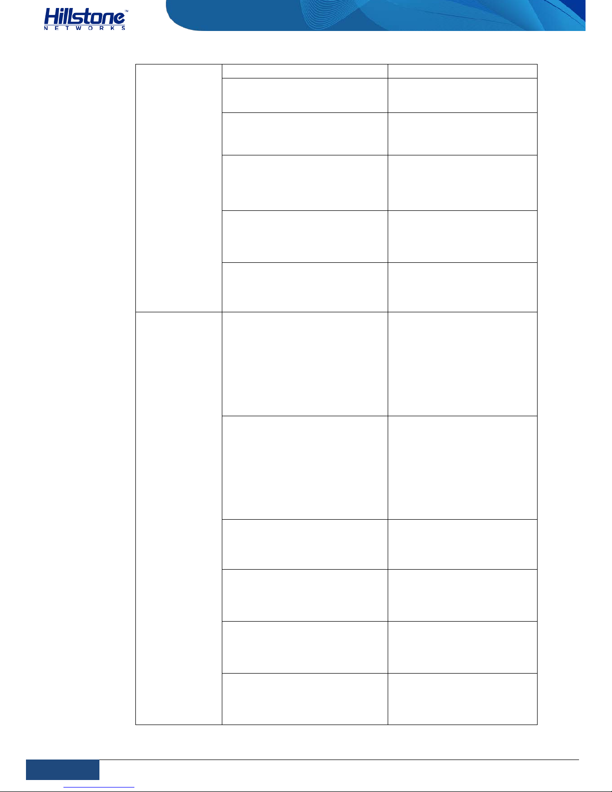
16
Chapter 1 Introduction | Hillstone
Hillstone SG-6000 E-Series Hardware Reference Guide
(W×D×H)
SG-6000-E6160
110.0mm
SG-6000-E5960
SG-6000-E5760
SG-6000-E5660
440.0 mm x 520.0 mm x
88.0 mm
SG-6000-E5560
SG-6000-E5260
SG-6000-E3965
440.0mm x 530.0mm x
88.0mm
SG-6000-E3960
SG-6000-E3662
SG-6000-E3660
SG-6000-E2860
436.0 mm x 365.5 mm x
44.0 mm
SG-6000-E2800
SG-6000-E2300
SG-6000-E1700
SG-6000-E1606
442.0 mm x 240.7 mm x
44.0 mm
SG-6000-E1600
SG-6000-E1100 (WLAN version)
SG-6000-E1100 (WLAN+3G
version)
320.0mm x 150.0mm x
44.0mm
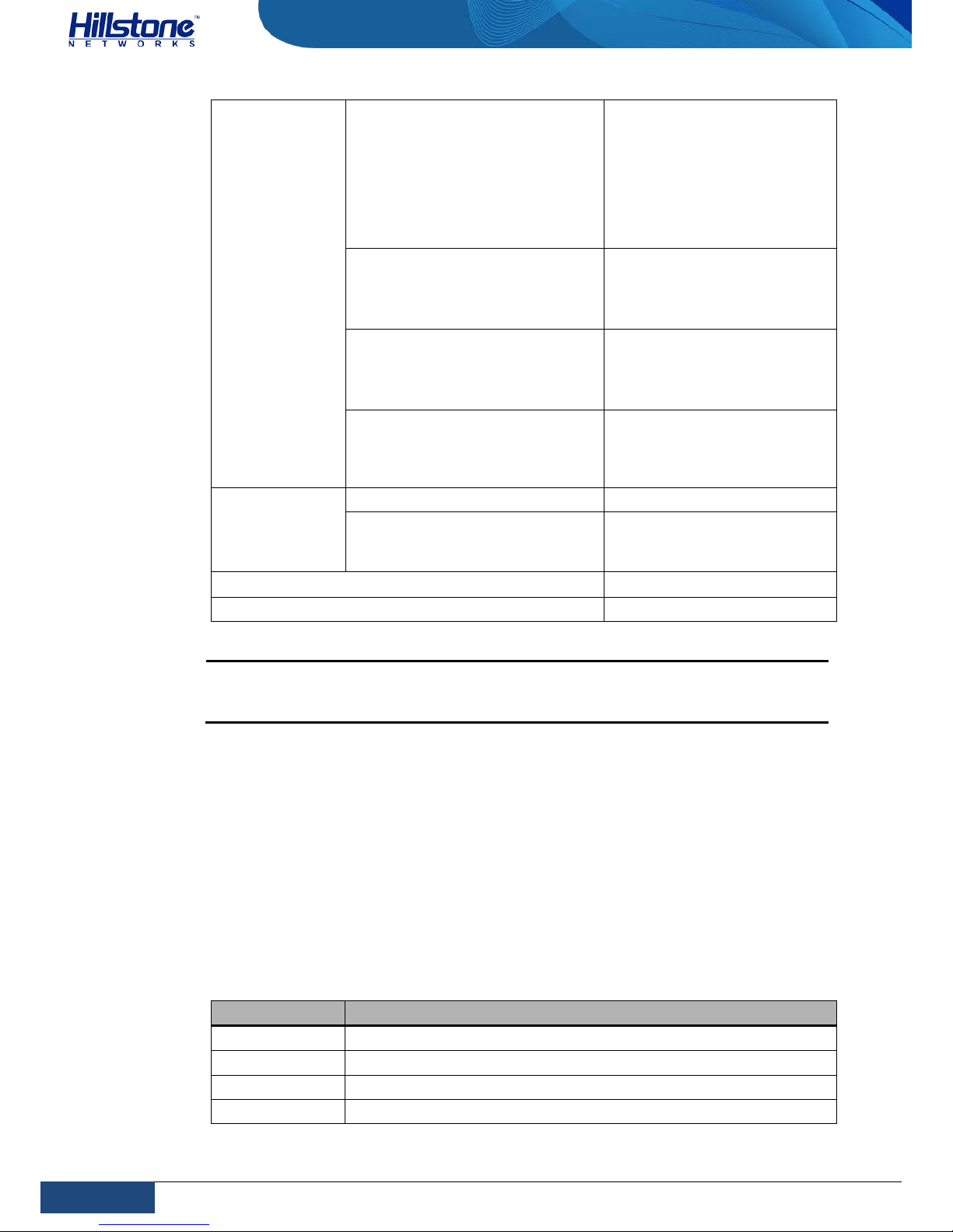
Weight
SG-6000-E6360
SG-6000-E6160
et weight: 13.8 kg
Gross weight: 18.3 kg
(accessories and packages
included)
SG-6000-E3960
SG-6000-E3662
SG-6000-E3660
SG-6000-E2860
et weight: 5.6 kg
Gross weight: 9.1 kg
(accessories and packages
included)
SG-6000-E5960
SG-6000-E5760
SG-6000-E5660
Net weight: 12.3 kg
Gross weight: 16.8
kg(accessories and packages
included)
SG-6000-E5560
SG-6000-E5260
SG-6000-E3965
Net weight: 11.8 kg
Gross weight: 16.3 kg
(accessories and packages
included)
SG-6000-E2800
SG-6000-E2300
SG-6000-E1700
SG-6000-E1606
Net weight: 2.5 kg
Gross weight: 5.3 kg
(accessories and packages
included)
SG-6000-E1600
SG-6000-E1100 (WLAN version)
SG-6000-E1100 (WLAN+3G
version)
Net weight: 1.5 kg
Gross weight: 2.0 kg
(accessories and packages
included)
Page 24
17
Chapter 1 Introduction | Hillstone
Hillstone SG-6000 E-Series Hardware Reference Guide
Power Rating
SG-6000-E6360
SG-6000-E6160
SG-6000-E5960
SG-6000-E5760
SG-6000-E5660
SG-6000-E5560
SG-6000-E5260
SG-6000-E3965
450 W
SG-6000-E3960
SG-6000-E3662
SG-6000-E3660
SG-6000-E2860
150 W
SG-6000-E2800
SG-6000-E2300
SG-6000-E1700
SG-6000-E1606
45 W
SG-6000-E1600
SG-6000-E1100 (WLAN version)
SG-6000-E1100 (WLAN+3G
version)
30 W
Input Voltage
AC 100-240V AC, 50/60Hz
DC
-40 - -60V DC (except for
SG-6000-E1600/SG-6000E1100)
Ambient Temperature
0℃-40℃
Relative Humidity 10%-95% (non-condensing)
Note: DDR SDRAM is the random access memory to store the communication
data for the CPU. Flash Memory is used for storing the operating system
firmware, configuration and application files.
Ports
This section introduces attributes of interfaces (ports) on the Hillstone devices,
including console port, auxiliary port, USB port, gigabit copper port, SFP port,
QSFP+ portsand XFP port.
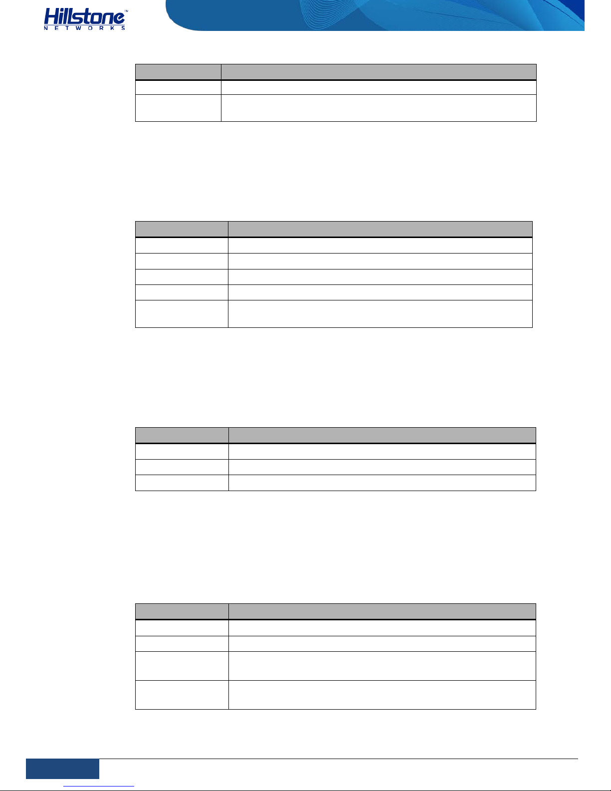
Console Port
Hillstone device provides an RS-232C asynchronous se rial console port for you to
configure the device. Attributes for the console (CON) port are shown in the
following table.
Table 1-17: Console Port Attributes
Attribute Description
Connector RJ-45
Port Standard RS-232C
Baud Rate 9600/19200/38400/57600/115200 bit/s
Services
Connect the CON port to the serial port of a PC and run a
Page 25
18
Chapter 1 Introduction | Hillstone
Hillstone SG-6000 E-Series Hardware Reference Guide
Attribute Description
terminal emulation program on the PC to configure the device.
Transmission
Medium
console cable
Auxiliary Port
Hillstone device provides an RS-232C asynchronous serial auxiliary (AUX) port.
Attributes for the auxiliary port are shown in the following table.
Table 1-18: Auxiliary Port Attributes
Attribute Description
Connector RJ-45
Port Standard RS-232C
Baud Rate 9600/19200/38400/57600/115200 bit/s
Services Aux port is used for debugging.
Transmission
Medium
console cable
USB Port
Hillstone device provides up to two USB host ports. Attributes for the USB port are
shown in the following table.
Table 1-19: USB Port Attributes
Attribute Description
Connector USB Type-A interface
Port Standard USB 2.0 host interface
Negotiation Mode 1.1/2.0 autosensing
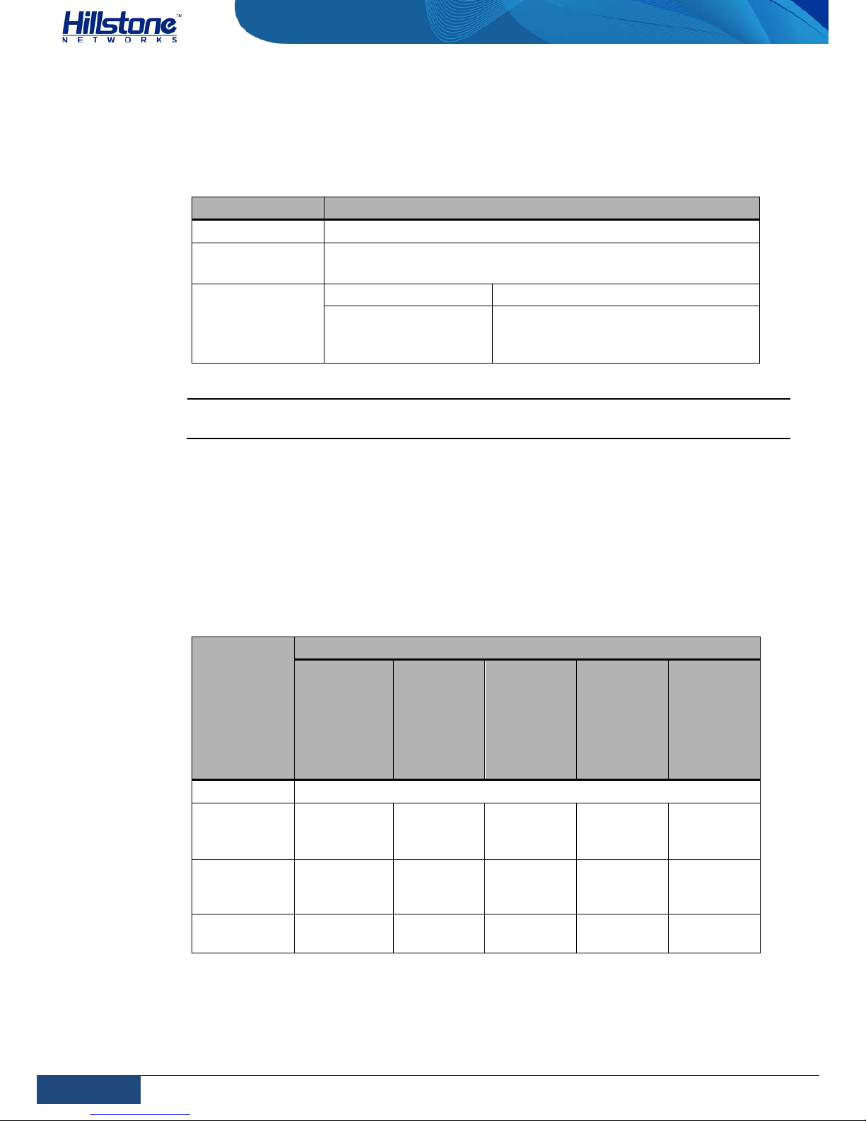
Gigabit Copper Port
Hillstone device provides several fixed gigabit copper ports; the gigabit Combo port
also supports the copper cable connection. Attr ib utes for the gigabit copper port are
shown in the following table.
Table 1-20: Gigabit Copper Port Attributes
Attribute Description
Connector RJ-45
Port Standard Auto-MDIX
Frame Format
Ethernet_II
Ethernet_SNAP
Negotiation Mode
10/100/1000Mbps autosensing
Full/half-duplex
Page 26
19
Chapter 1 Introduction | Hillstone
Hillstone SG-6000 E-Series Hardware Reference Guide
SFP Port
Hillstone device supports SFP ports. The following table describes the attributes of
SFP port.
Table 1-21: SFP Port Attributes
Attribute Description
Connector SFP
Frame Format
Ethernet_II
Ethernet_SNAP
Negotiation Mode
SFP optical module 1000Mbps
SFP copper module
10/100/1000Mbps autosensing
(some only supports 1000Mbps)
Full / half-duplex
Caution: To avoid dust falling into the SFP socket, you should place a rubber dust cap
(originally in the accessory box) over the SFP port.
The SFP port has two types of interface transceiver module for you to choose:
♦ SFP optical module/transceiver
♦ Copper SFP transceiver
If you choose to use SFP optical module in SFP port, y ou should use LC-Type optical
connector. Hi ll ston e device supports five types of 1000Base-FX SFP optical modules.
All optical modules are hot-swappable.
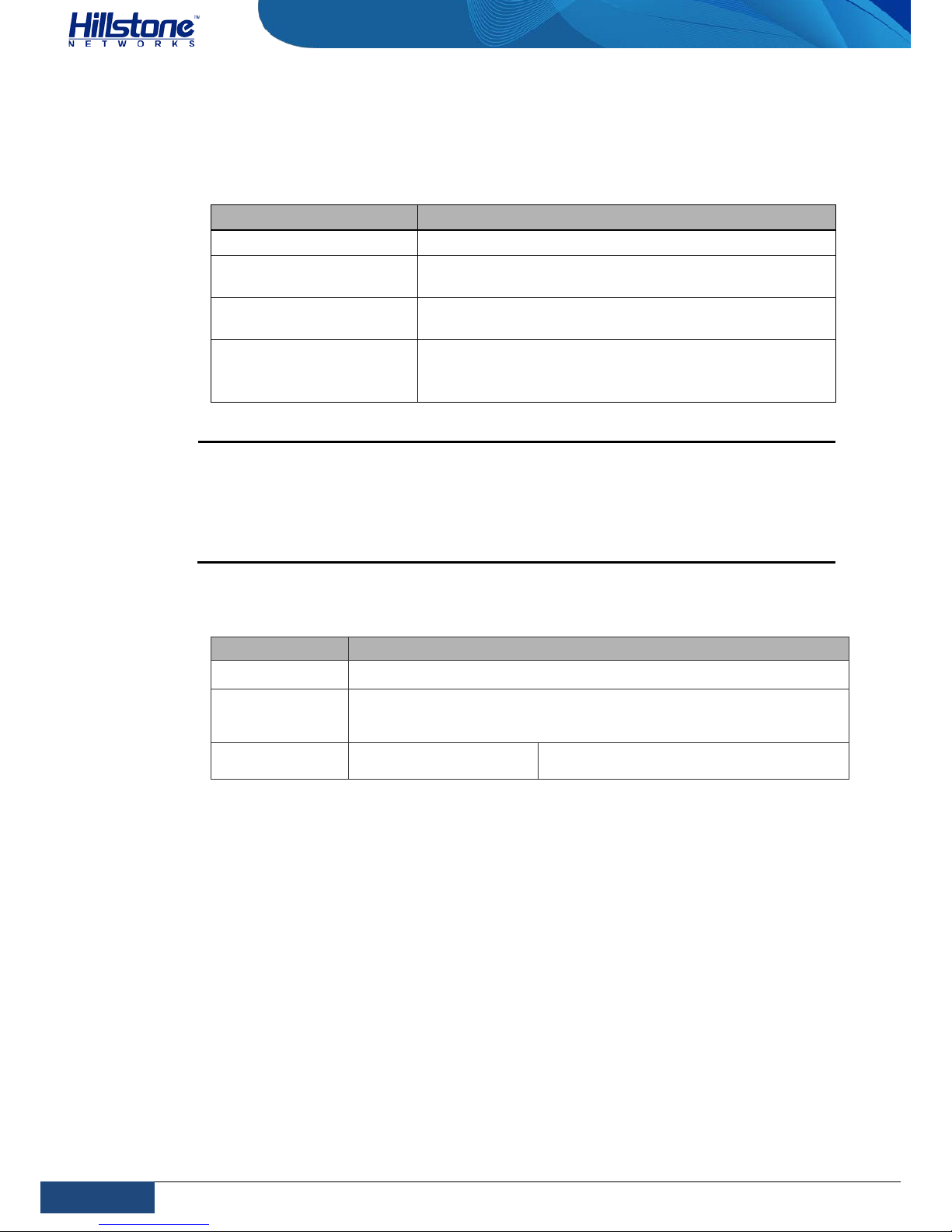
Table 1-22: SFP Optical Module Attributes
Attribute
Description
Short-haul
Multimode
Optical
Module
(850nm)
Mediumhaul
Singlemode
Optical
Module
(1310nm)
Long-haul
Singlemode
Optical
Module
(1310nm)
Long-haul
Singlemode
Optical
Module
(1550nm)
Ultra-long
Haul
Singlemode
Optical
Module
(1550nm)
Connector LC
Fiber Type
62.5/125μm
multi-mode
fiber
9/125μm
single-
mode fiber
9/125μm
single-
mode fiber
9/125μm
single-
mode fiber
9/125μm
single-
mode fiber
Maximum
Transmission
Distance
0.55km 10km 40km 40km 70km
Central
Wavelength
850nm 1310nm 1310nm 1550nm 1550nm
Page 27
20
Chapter 1 Introduction | Hillstone
Hillstone SG-6000 E-Series Hardware Reference Guide
If you choose to use copper SFP transceiver in SFP port, you should use crossover
or straight-through cable (i.e. standard Ethernet cable). The following table
describes the attributes of copper SFP transceiver.
Table 1-23: SFP Copper Module Attributes
Attribute Description
Connector RJ-45
Port Standard
Auto-MDI/MDIX (crossover cable and straight-through
cable autosensing)
Maximum Transmission
Distance
100m
Negotiation Mode
10/100/1000Mbps autosensing (some only supports
1000Mbps)
Full / half-duplex
Cautions:
♦ The SFP electric modules of all platforms only support 1000Mbps.
♦ Before switch ing between the optical and copper cable connection on
Combo ports, you need to first clear the rate and duplex mode
configurations in the current operating mode (copper or optical), and reconfigure the port after the switching.
SFP+ Port
Table 1-24: SFP+ Port Attributes
Attribute Description
Connector SFP+
Frame Format
Ethernet_II
Ethernet_SNAP
Negotiation
Mode
SFP+ optical module
10Gbps
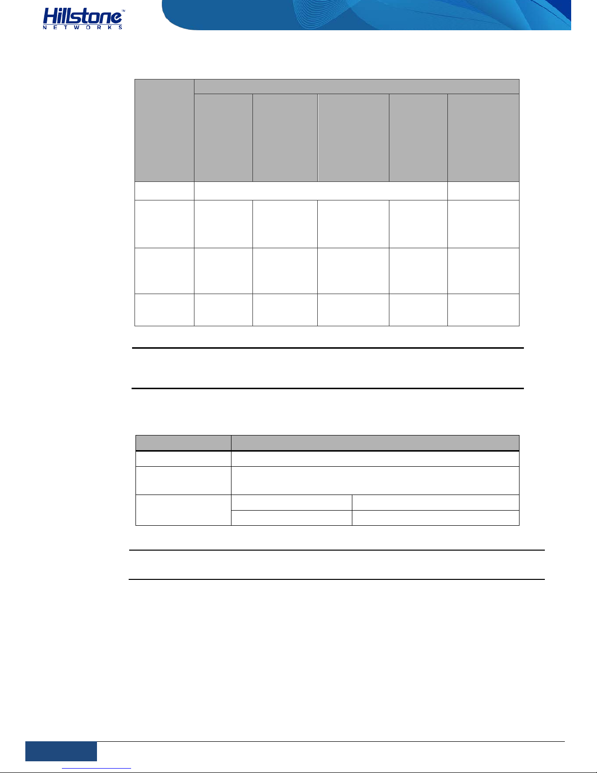
If you choose to use SFP+ optical module in SFP+ port, you should use LC-Type
optical connector. Hillstone device supports five types of 10G Base-FX SFP+ optical
modules. All optical modules are hot-swappable.
Page 28
21
Chapter 1 Introduction | Hillstone
Hillstone SG-6000 E-Series Hardware Reference Guide
Table 1-25: SFP+ Optical Module Attributes
Attribute
Description
Shorthaul
Multimod
e Optical
Module
(850nm)
Short-haul
Multimode
Optical
Module
(850nm)
Mediumhaul singlemode
Optical
Module
(1310nm)
Long-haul
Singlemode
Optical
Module
(1550nm)
Ultra-long
Haul Singlemode
Optical
Module
(1550nm)
Connector
LC
Fiber Type
50/125μm
multi-mode
fiber
62.5/125μm
multi-mode
fiber
9/125μm
single-mode
fiber
9/125μm
single-
mode fiber
9/125μm
single-mode
fiber
Maximum
Transmissio
n Distance
0.3km 0.033km 10km 40km 80km
Central
Wavelength
850nm 850nm 1310nm 1550nm 1550nm
Caution:
• To avoid dust falling into the SFP+ socket, you should place a rubber dust cap
(provided in the accessory box) over the SFP+ port.
QSFP+ Port
Table 1-26: QSFP+ P ort Attributes
Attribute Description
Connector QSFP+
Frame Format
Ethernet_II
Ethernet_SNAP
Negotiation Mode
40GE 1*40Gbps
4*10GE 4*10Gbps
Caution: When the negotiation mode of QSFP+ port changed, you need to reboot
the device to make it effective.
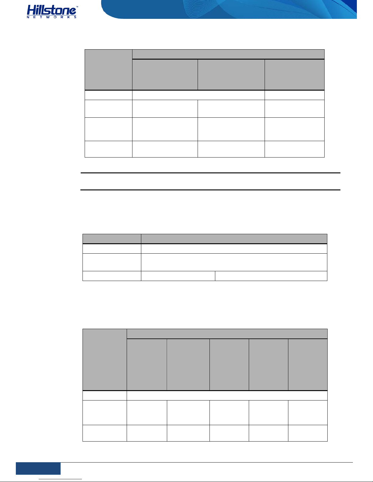
Three types of QSFP+ optical module are supported. The optical modules are
available with LC-type connectors and MPO-type connectors and are all hotswappable.
Page 29
22
Chapter 1 Introduction | Hillstone
Hillstone SG-6000 E-Series Hardware Reference Guide
Table 1-27: QSFP+ Optical Module Attributes
Attribute
Description
Short-haul
Multimode Optical
Module (850nm)
Short-haul
Multimode Optical
Module (850nm)
Ultra-long Haul
Single-mode
Optical Module
(1550nm)
Connector MPO LC
Fiber Type
50/125μm
multimode fiber
50/125μm multimode fiber
9/125μm singlemode fiber
Maximum
Transmission
Distance
0.1km 0.3km 10km
Central
Wavelength
850nm 850nm 1310nm
Caution: To avoid dust falling into the QSFP+ socket, you should place a rubber dust
cap (originally in the accessory box) over the QSFP+ port.
XFP Port
Hillstone devices support XFP ports which use XFP optical modules.
Table 1-28: XFP Port Attributes
Attribute Description
Connector XFP
Frame Format
Ethernet_II
Ethernet_SNAP
Negotiation Mode XFP optical module 10Gbps
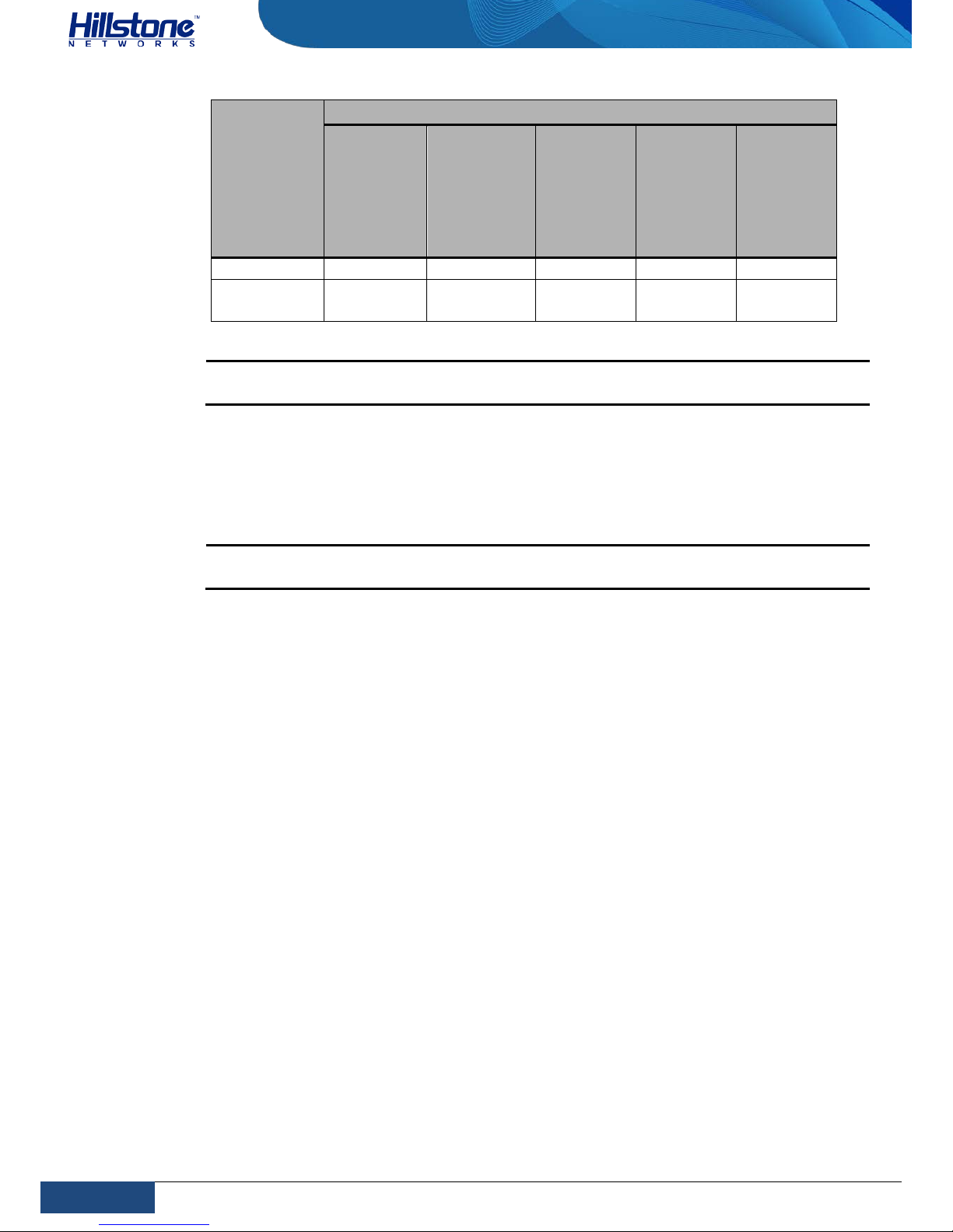
Hillstone device supports five types of 10GBase-FX XFP optical module. All optical
modules are hot-swappable.
Table 1-29: XFP Optical Module Attributes
Attribute
Description
Shorthaul
Multimode
Optical
Module
(850nm)
Short-haul
Multimode
Optical
Module
(850nm)
Mediumhaul
Singlemode
Optical
Module
(1310nm)
Long-haul
Singlemode
Optical
Module
(1550nm)
Ultra-long
Haul
Singlemode
Optical
Module
(1550nm)
Connector LC
Fiber Type
50/125μm
multimode
fiber
62.5/125μm
multi-mode
fiber
9/125μm
single-
mode fiber
9/125μm
single-
mode fiber
9/125μm
single-
mode fiber
Maximum
Transmission
0.3km
(984.3ft)
0.033km
(108.3ft)
10km 40km 80km
Page 30
23
Chapter 1 Introduction | Hillstone
Hillstone SG-6000 E-Series Hardware Reference Guide
Attribute
Description
Shorthaul
Multimode
Optical
Module
(850nm)
Short-haul
Multimode
Optical
Module
(850nm)
Mediumhaul
Singlemode
Optical
Module
(1310nm)
Long-haul
Singlemode
Optical
Module
(1550nm)
Ultra-long
Haul
Singlemode
Optical
Module
(1550nm)
Distance
Central
Wavelength
850nm 850nm 1310nm 1550nm 1550nm
Caution: To avoid dust falling into the XFP socket, you should place a rubber dust cap
(originally in the accessory box) over the XFP port.
CLR Button
The CLR button is the pinhole of the front panel and is used t o reset the device
back to the factory default settings. You ca n restore access to the device with this
button if the login password is lost.
Warning: Use this button with caution. Resetting the device will clear all existing
configurations.
To restore the factory default settings, take the following steps:
1. Turn off the power of the device.
2. Press the CLR button in the pinhole and switch on the power supply
simultaneously.
3. Keep pressing till the STA and ALM LEDs turn to constantly red, then stop
pressing. The device begins to restore to the original factory settings.
4. The system reboots after the default settings restored.
When you reset SG-6000-E6360, SG-6000-E6160, SG-6000-E5260, SG-6000E5560, SG-6000-E3965, SG-6000-E3960, SG-6000-E3960-GM, SG-6000-E3662,
SG-6000-E3660, SG-6000-E3660-GM and SG-6000-E2860, take the following steps:
1. When the device is working, press the CLR button in the pinhole and the
device will restart.
2. After the device restarted, the CON port outputs the information of CLR
button pressed and the STA and ALM LEDs turn to constantly re d. After the
LEDs turn off, the device will restart again.
Expansion Slot
The chassis height of SG-6000-E6360 and SG-6000-E6160 is 2.5U with two half-U
expansion slots (Slot 1-2) and one half-U Bypass expansion slot.
Page 31
24
Chapter 1 Introduction | Hillstone
Hillstone SG-6000 E-Series Hardware Reference Guide
The chassis height of SG-6000-E3965,SG-6000-E5260, SG-6000-E5560, SG-6000E5660, SG-6000-E5760, and SG-6000-E5960 is 2U with four half-U expansion slots
(Slot 1-4). The chassis height of SG-6000-E3960, SG-6000-E3960-GM, SG-6000E3662, SG-6000-E3660, SG-6000-E3660-GM and SG-6000-E2860 is 1U with two
half-U expansion slots (Slot 1-2).
♦ Half-U expansion slot fits in a ny slot.
♦ 1U height expansion modules can only be installed in Slot2 and Slot4.
♦ Some devices support more than one expansion modules of the same type.
Cautions:
♦ Cover the expansion slot with blank panel if the slot has no expansion
module installed.
♦ For detailed information of expansion modules, see Hillstone SG-6000
M_G_E Series Expansion Modules Reference Guide.
Power Supply
Single/Dual power supply: Some product modules adopt single power supply,
while others adopt dual power supplies, i.e. there are two power inputs installed in
one device. Dual power supplies ensure uninterrupted power by instantly enabling
the standby power supply when the active power supply fails to work.
AC/DC power supply: For some product modules (as l isted below), you can
choose either AC or DC power supply.
Hot-swappable: According to whether the power supply is hot-swappable or not,
the power supply is classifies into three types:
♦ Hot-swappable power supplies are removable modules which can be
replaced at any time;
♦ Fixed power supplies are irreplaceable and cannot be removed.
♦ External power adapter connects to the external AC power supply.
For instructions on how to replace power supply modules, refer to
Installing and
Removing the Power Supply Module.
Table 1-30: Power Supplies of All Product Models
Model Description AC/DC Power Supply Type
SG-6000-E6360
SG-6000-E6160
Single/Dual AC/DC Hot-swappable
SG-6000-E5960
Single/Dual
AC/DC
Hot-swappable
SG-6000-E5760
Single/Dual
AC/DC
Hot-swappable
SG-6000-E5660
Single/Dual
AC/DC
Hot-swappable
SG-6000-E5560
Dual
AC/DC
Hot-swappable
SG-6000-E5260
Dual
AC/DC
Hot-swappable
SG-6000-E3965
Dual
AC/DC
Hot-swappable
SG-6000-E3960
Single/Dual
AC/DC
Fixed
Page 32
25
Chapter 1 Introduction | Hillstone
Hillstone SG-6000 E-Series Hardware Reference Guide
Model Description AC/DC Power Supply Type
SG-6000-E3662
Single/Dual
AC/DC
Fixed
SG-6000-E3660
Single/Dual
AC/DC
Fixed
SG-6000-E2860
Single/Dual
AC/DC
Fixed
SG-6000-E2800
Single/Dual
AC/DC
Fixed
SG-6000-E2300
Single/Dual
AC/DC
Fixed
SG-6000-E1700
Single/Dual
AC/DC
Fixed
SG-6000-E1606
Single/Dual
AC/DC
Fixed
SG-6000-E1600
Single
AC
External
SG-6000-E1100
(WLAN version)
Single AC External
SG-6000-E1100
(WLAN+3G
version)
Single AC External
Power Module
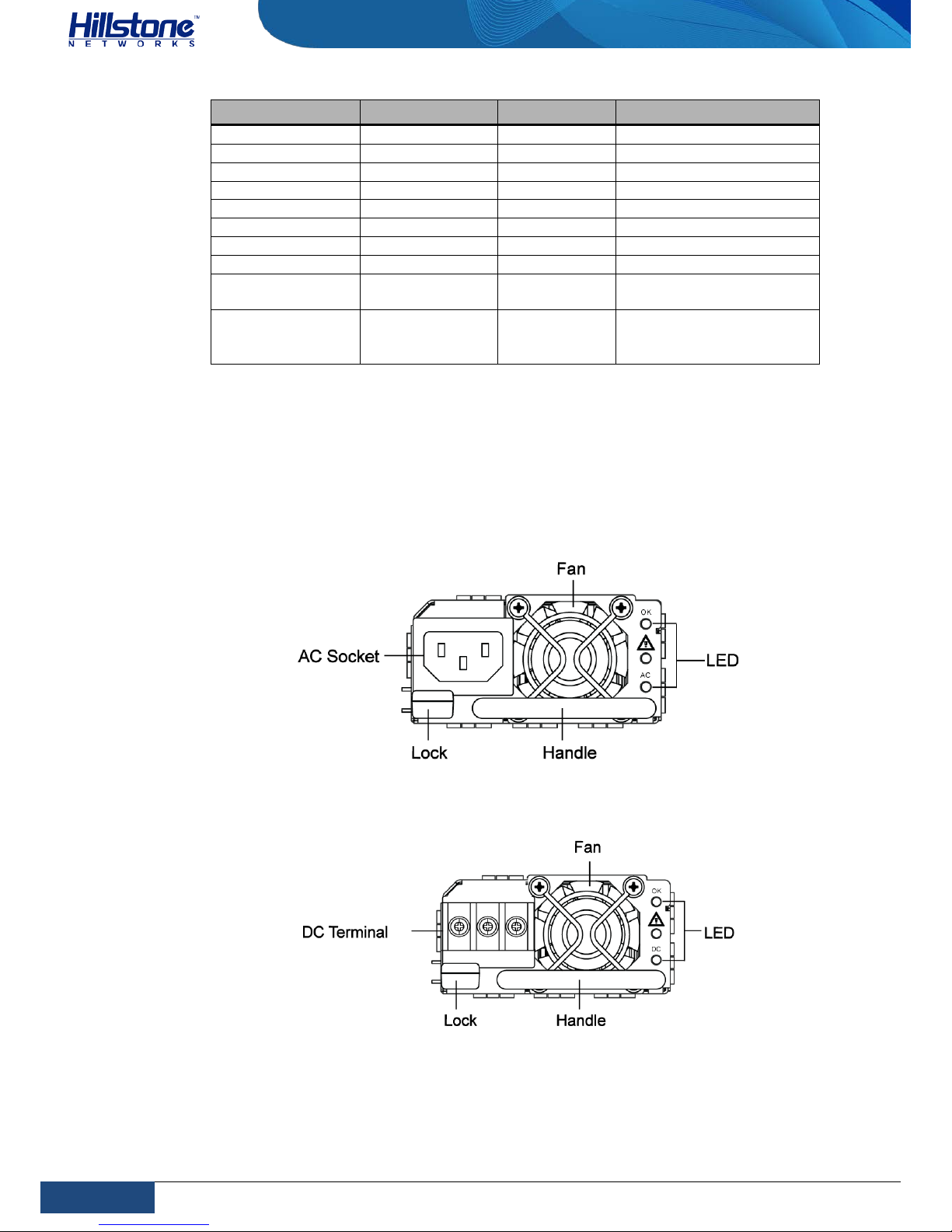
Hillstone designs a model of pluggable module for SG-6000-E3965, SG-6000-E5260,
SG-6000-E5660, SG-6000-E5760, SG-6000-E5960, SG-6000-E6160 and SG-6000E6360. Both AC and DC power modules are available. You can choose the power
type at your own choice.
Figure 1-19: AC Power Module
Figure 1-20: DC Power Module
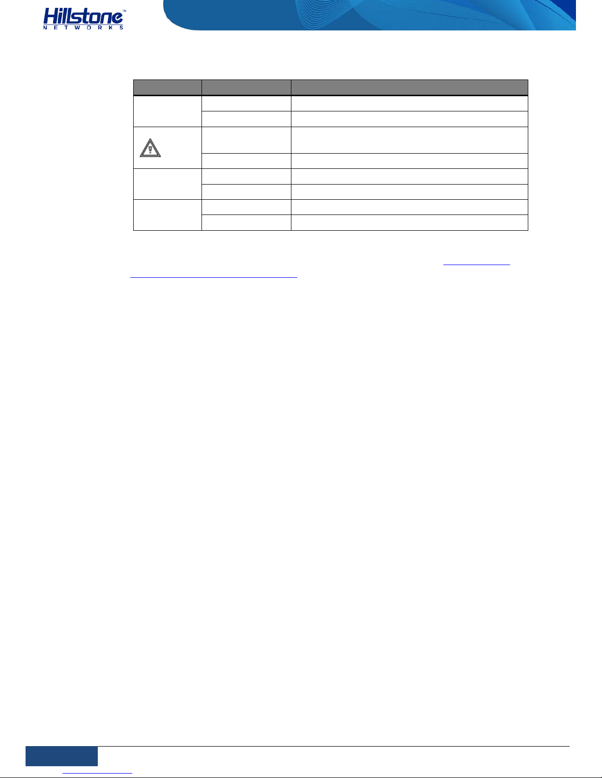
The power LED description for is listed in the following table.
Page 33
26
Chapter 1 Introduction | Hillstone
Hillstone SG-6000 E-Series Hardware Reference Guide
Table 1-31: Power Supply Modu le LED Descriptions
LED Color/Status Description
OK
Green/Alway s on Power module is functioning normally.
Off No power input.
Yellow/Always
on
Power module has error.
Off Power module is functioning norma lly.
AC
Green/Alway s on AC power module is functioning normally.
Off AC power module is powered off or has failed.
DC
Green/Alway s on DC power module is functioning norma lly.
Off DC power module is powered off or has failed.
For information on power module installation and replacement, see
Installing and
Removing the Power Supply Module.
Expansion Modules
SG-6000-E3965, SG-6000-E5260, SG-6000-E5660, SG-6000-E5760, SG-6000E5960, SG-6000-E6160 and SG-6000-E6360 are designed with general expansion
slots for expansion modules. The supported expansion module types may vary from
platforms, s pecifically includin g interface module and storage module. The main
functions of these expansion modules are:
♦ Interface module: Expands the number of ports.
♦ Storage module: Enlarges the hardware space for storing logs.
♦ Bypass module: Bypass module connects two networks. Data between them
are transferred by the device in the normal condition. When a specific incident
occurs (like sudden power failure or system reboot), the two networks are
connected directly by the bypass module, ther efore, the device is bypassed.
For detailed information about expansion modules, see Hillstone SG-6000 M_G_E
Expansion Modules Reference Guide.
Page 34
27
Chapter 2 Installation Preparations | Hillstone
Hillstone SG-6000 E-Series Hardware Reference Guide
Chapter 2 Installation Preparations
Introduction
To prevent personnel injury and equipment damage, please carefully read all the
safety warnings and cautions in this chapter before the insta l lation.
Hillstone products are designed for indoor use. To ensure the normal operation and
to pro long the service lifetime, the installation site mu st meet the following
requirements:
Cleanness Requirements
Table 2-1: Dust Concentration Requirements in the Equipment Room
Mechanical Active
Material
Unit Content
Dust particle particle/m3
≤3×10⁴ (No visible dust on the table in
3 days)
Note:Diameter of dust particle≥5μm
ESD Prevention
To prevent electrostatic discharge (ESD) damage, ensure that:
♦ The device is well grounded. The grounding screw is properly grounded.
♦ Take dustproof measures for the equipment room.
♦ Maintain proper humidity and temperature levels.
♦ Do not disassemble the equipment without permission from the vendor, or
you may cause danger and void your warranty.
EMI Prevention
All possible electromagnetic interference (EMI) sources, external or internal, can
affect the device by capacitance coupling, inductance coupl ing, electromagnetic
radiation, and common impedance coupling (including the grounding system).
To prevent or reduce EMI:
♦ Take measures to protect the power system from power interference.
♦ It’s better to separate the floor where the device is installed from the
grounding device and lighting-proof device of the power source.
♦ Keep the device away from radio stations, radar, and other high-frequency
and high-current devices.
Page 35

28
Chapter 2 Installation Preparations | Hillstone
Hillstone SG-6000 E-Series Hardware Reference Guide
♦ Use electromagnetic shielding when necessary.
Grounding Requirements
To use the device more safely :
♦ Ensure that the gro und ing screw of the chassis is well gr ounded via the
grounding wire.
♦ Ensure that the grounding pin of the power plug is well gro unded.
Workbench Requirements
Before the installation, ensure your workbench is properly prepared as follows:
♦ Make sure that you provide adequate space near the intake and exhaust vents
of the device for heat dissipation.
♦ Make sure the rack is equipped with a good ventilation system.
♦ Make sure the rack is strong enough to support the weight of a fully equipped
device.
♦ Make sure the rack is well grounded.
Other Safety Recommendations
The directions below are also recommended for you to follow:
♦ Keep the device far away from moist areas and heat sources.
♦ Wear an ESD wrist strap correctly when handling the device.
♦ Be careful with laser emission. Do not directly stare into apertures of fiber-
optic connectors that emit laser radiation.
♦ Use uninterrupted power supply (UPS).
Unpacking
Verify the parts received according to your purc ha sing contract and packing list to
ensure that you have received all the items necessary. If you have any problem,
please contact your sales representative.
Installation Devices/Tools/Cables
A Hillstone device is shipped with a power cable and a console cable, and you
should have the following items before the installation:
♦ Terminal: Configuration terminal (e.g. an ordinary PC).
♦ Tools: Philips screwdrivers and ESD wrist strap.
Page 36

29
Chapter 2 Installation Preparations | Hillstone
Hillstone SG-6000 E-Series Hardware Reference Guide
♦ Cables: Power cable, console cable and Ethernet cable.
Page 37
30
Chapter 3 Installation | Hillstone
Hillstone SG-6000 E-Series Hardware Reference Guide
Chapter 3 Installation
Before Installation
A yellow seal with dark ink characters is stuck on a mounting screw of the chassis.
Keep the seal intact. The sales representative will check this seal before
maintenance operation. Please get the permission of your sales representative
before opening the chassis yourself. Warranty will be void if you disassemble the
chassis without authorization.
Before installation, make sure that:
♦ You have read Chapter 2 Installation Preparations
carefully.
♦ The requirements in Chapter 2 Installation Preparations are satisfied.
Hillstone products can be installed:
♦ On a workbench
♦ On a standard 19-inch rack
Installing the Device on a Workbench
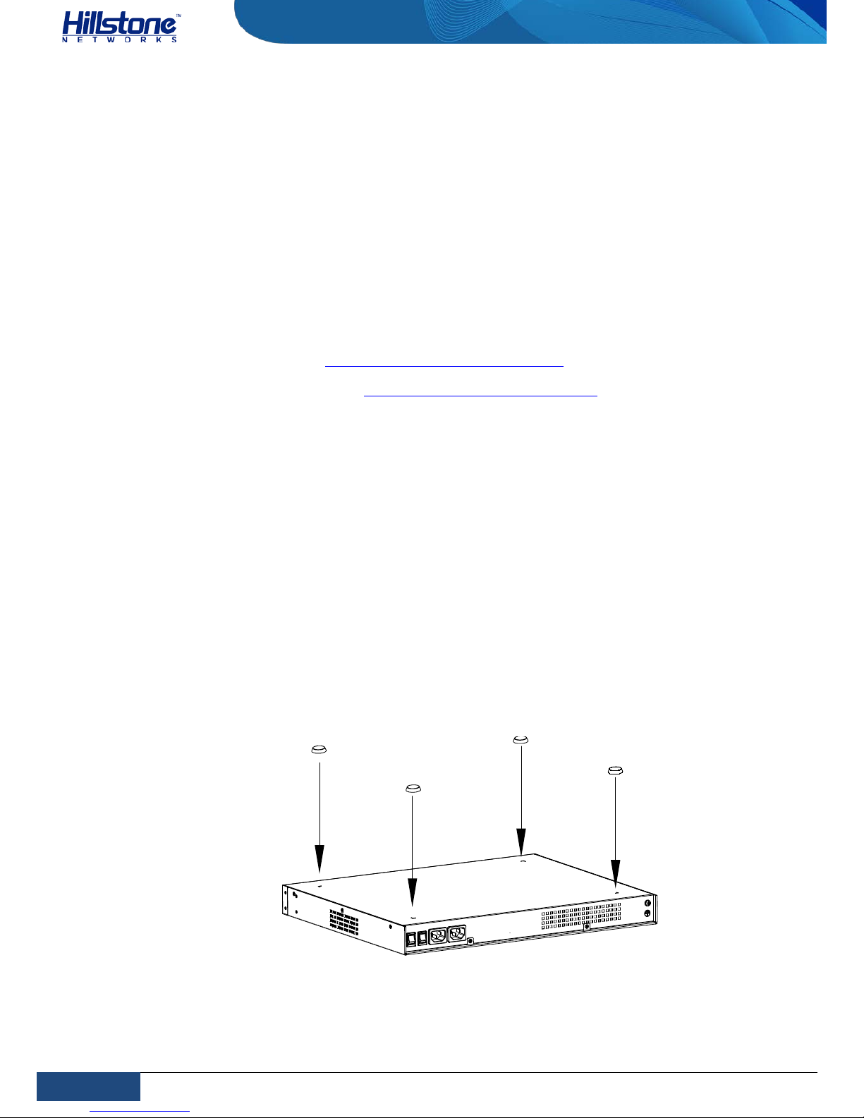
Hillstone product can be placed on a stable and clean workbench. For skid
prevention, take the following steps to fit anti-skid pads on the device before
installing:
Step 1: Tear off the sticke r from the rubber pad.
Step 2: Press the sticky side of the pad to the right-angle die-pressed mark on the
bottom panel of the chassis. See Figure 3-1.
Figure 3-1: Installing the Rubber Pads
Check the following specifications when installing the device on a workbench:
Page 38
31
Chapter 3 Installation | Hillstone
Hillstone SG-6000 E-Series Hardware Reference Guide
♦ Make sure the workbench is stable and well grounded.
♦ Make sure the intake and the exhaust vents are unblocked, and keep the
device well ventilated.
♦ Do not place any heavy object on the top of the chassis.
Installing the Device on a Rack
Before mounting the device on a rack, ensure that the power is off, and the rack is
stable enough and well grounded. Hillstone devices are designed for a 19-inch
standard rack.
To mount the chassis on a rack:
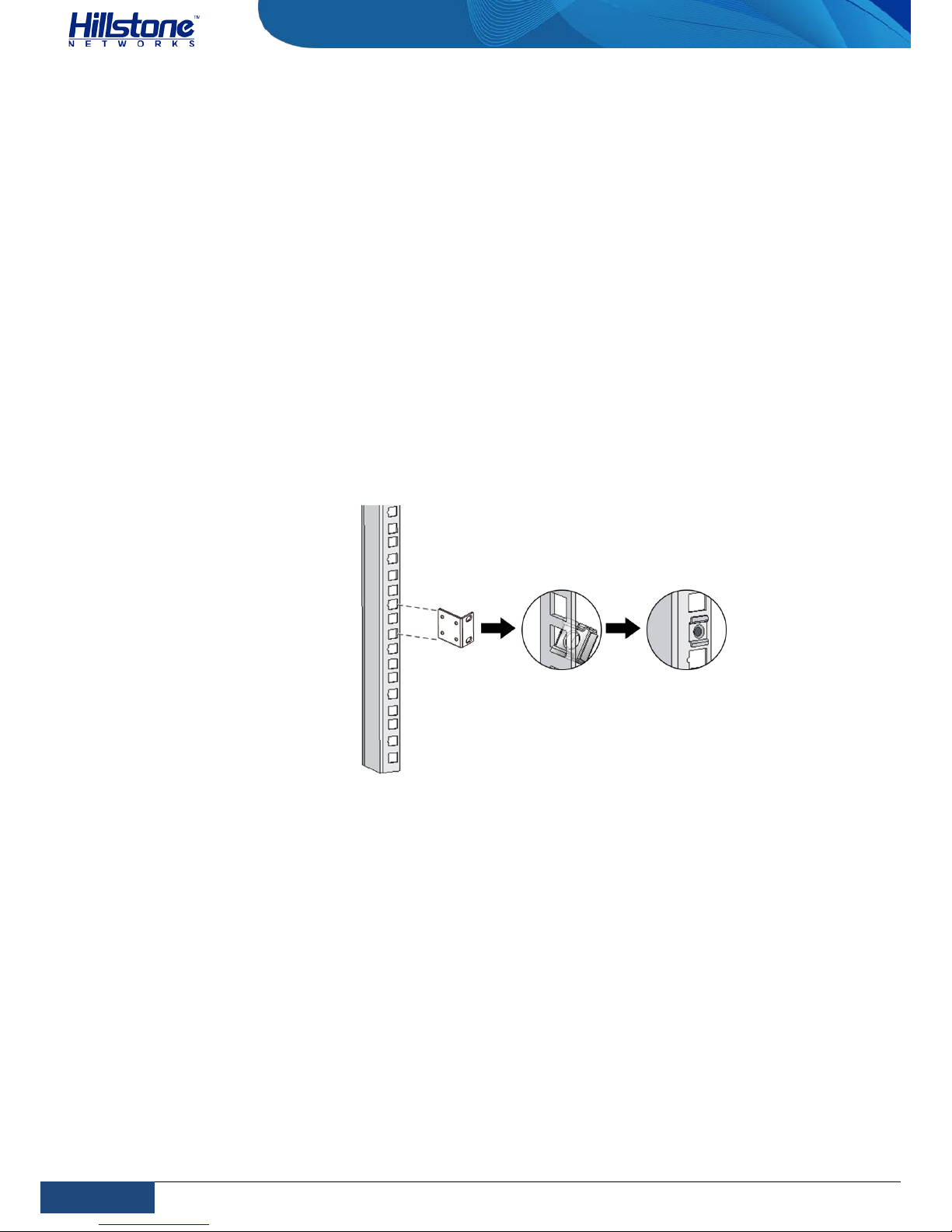
Step 1:Use rack-mounting ear to mark the positions of floating nuts on the front
rack posts, as shown in Figure 3-2.
Figure 3-2: Installing the Floating Nuts
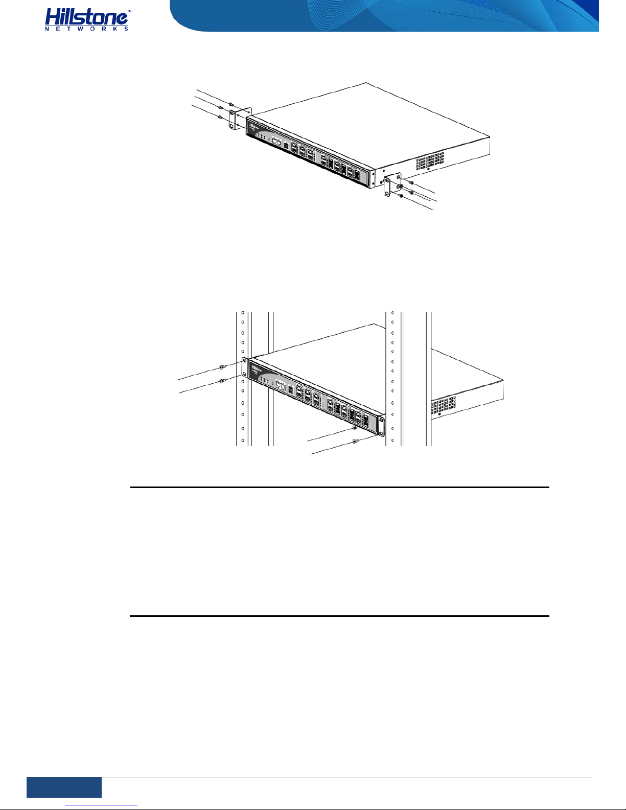
Step 2: Attach rack-mounting ears to the lef t and r ight side panels of the chassis
respectively, and then fasten the rack-mounting ears with suitable screws, as
shown in Figure 3-3.
Page 39
32
Chapter 3 Installation | Hillstone
Hillstone SG-6000 E-Series Hardware Reference Guide
Figure 3-3: Installing the Rack-mounting Ears (1U Chassis as example)
Step 3: Take out screws from the accessory box and fasten the rack-mounting ears
of the chassis in the rack with the screws. Keep the center of the rack-mounting ear
and the center of the rac k hole horizontally even, as shown in Figure 3-4.
Figure 3-4: Installin g the Device in a Rack (1U Chassis as example)
Cautions:
♦ The rack-mounting ears cannot bear weight. Make sure the chassis is
supported by the platform under it when mounted into a rack.
♦ For better ventilation, there should be a clearance space between two
equipments.
♦ If the rack accommodates only one device, put the de vice on the bottom.
♦ The floating nuts in the a ccessory box can only fit in the 9 mm x 9 mm
squared holes of standard racks and they can be used when no original
rack nuts are available.
Connecting Cables
This section describes how to connect cables to the device, including connecting the
ground wire, the console cable, the Ethernet cable and the power cable.
Page 40
33
Chapter 3 Installation | Hillstone
Hillstone SG-6000 E-Series Hardware Reference Guide
Connecting the Ground Wire
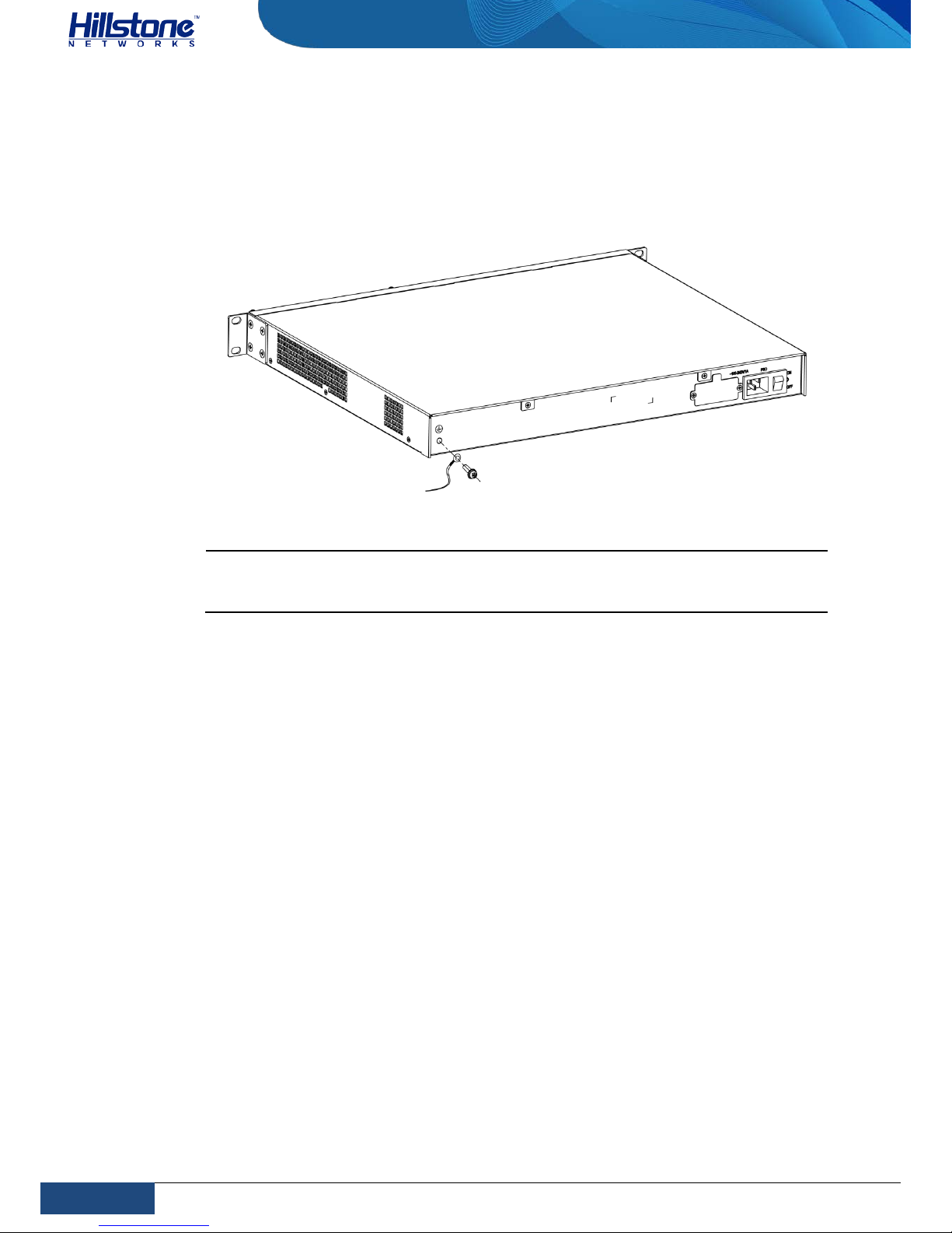
To meet safety requirements, you must correctly connect the grounding screw on
the chassis to the earth ground by a grounding wire. T he grounding resistance
should be less than 5Ω.
Figure 3-5: Connecting the Ground Wire (1U Chassis as example)
Warning: The correct connection of the ground wire on the chassis is an
essential safeguard against lightning shocks and interference. You must properly
connect the ground wir e when installing and using the device.
Connecting the Console Cable
Hillstone device provides an RS-232C asynchronous serial console (CON) port,
through which you can configure the device. The console cable is an 8-core shielded
cable, which has an RJ-45 connector that can be connected to the Console port of
the device and a DB-9 (female) connector that can be connected to the serial port
of a console terminal.
Perform the following steps to connect the device and the console terminal:
1. Select a console terminal. You may choose an ordinary PC or a standard
ASCII terminal with an RS-232C serial port.
2. Connect the console cable. Connect the RJ-45 end of the cable to the Console
port of the device, and then connect the DB-9 connector of the cable to the
console terminal.
Connecting the Ethernet Cable
Hillstone products provide 1000Mbps electrical Ethernet ports, SFP ports, XFP ports
and Ethernet Combo ports (Electrical port + Optical port). The electrical Ethernet
port can be connected by a straight-through cable (also called s tandard cable) or a
crossover cable. The SFP port should use a SFP optical module, wh ich can be
connected with crossover cable or straight-through cable, or use a SFP electric
Page 41
34
Chapter 3 Installation | Hillstone
Hillstone SG-6000 E-Series Hardware Reference Guide
module connected by a single-mode or multi-mode cable. The XFP port uses singlemode or multi-mode cables to access Ethernet.
All SFP Port and XFP Port
optical modules of Hillstone products use LC-type optical
connector; therefore, you should connec t the optical modules using optical fiber
ended with LC-type connector.
Connecting the Ethernet Copper Cable
Follow the guidelines below when connecting cab les to the ports:
♦ Be careful not to connect the Ethernet port to the wrong ports. Read the label
above the port carefully.
♦ For electrical Ethernet connection, use crossover cable or straight-through
cable.
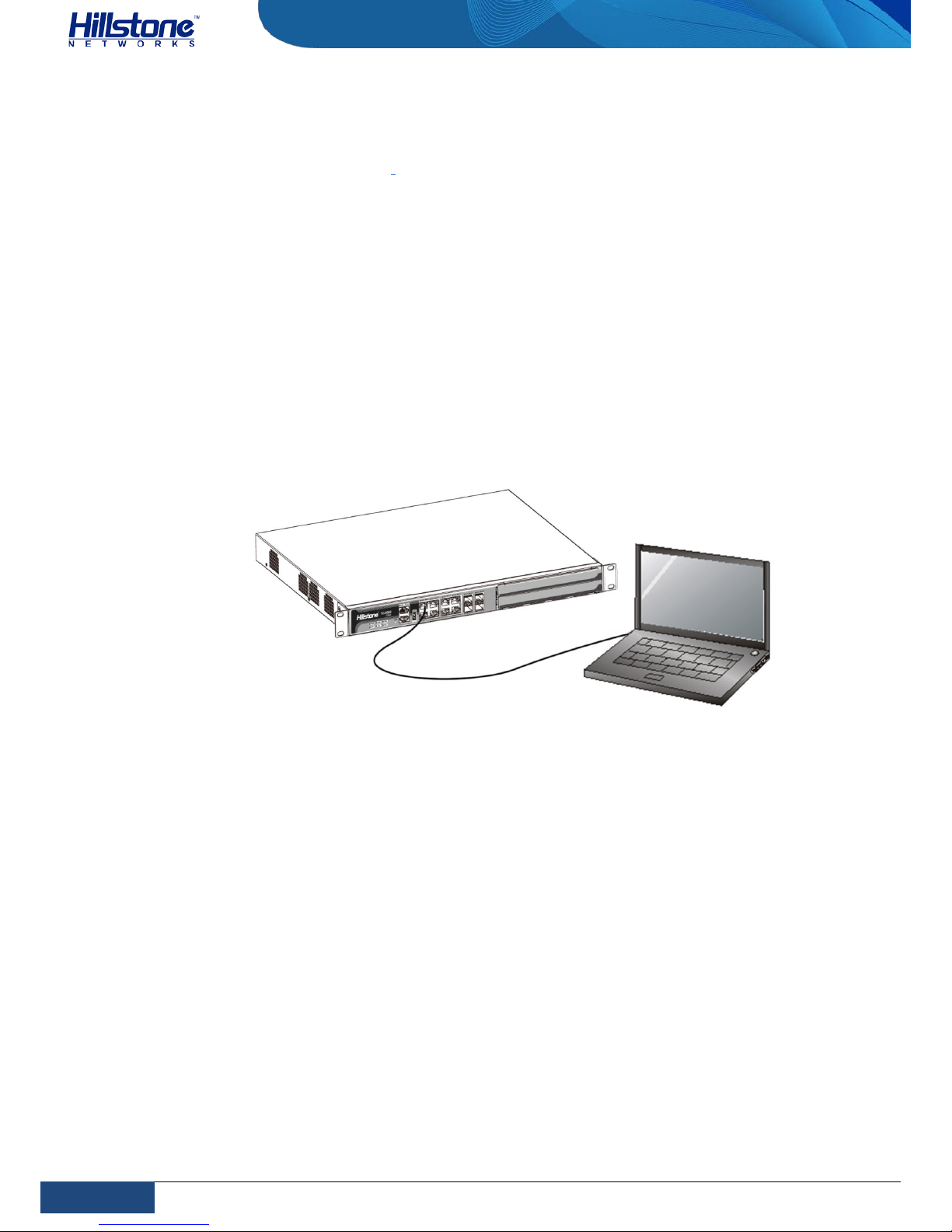
Figure 3-6: Connecting the E thernet Cop per Cable
Connecting the Ethernet Fiber Cable
Follow the guidelines below when connecting cab les to the ports:
♦ Be careful not to connect the Ethernet port to the wro ng ports. Read the label
above the port carefully.
♦ For SFP port connection, the optical module should be inserted into SFP port
before installing the LC-type connector to the optical module; the copper SFP
module should be connected by crossover cable or straight-through cable.
♦ For XFP ports, insert the XFP optical module into the XFP port before
connecting the LC-type co nnec tor to the module.
Keep the followings in mind when connecting fiber cables:
♦ The curvature radius should be greater than 10cm. Avoid excessive bending
of the cable.
♦ Ensure the Tx and Rx ends are connected correctly.
Page 42
35
Chapter 3 Installation | Hillstone
Hillstone SG-6000 E-Series Hardware Reference Guide
♦ Keep the connector of the optical cable clean.
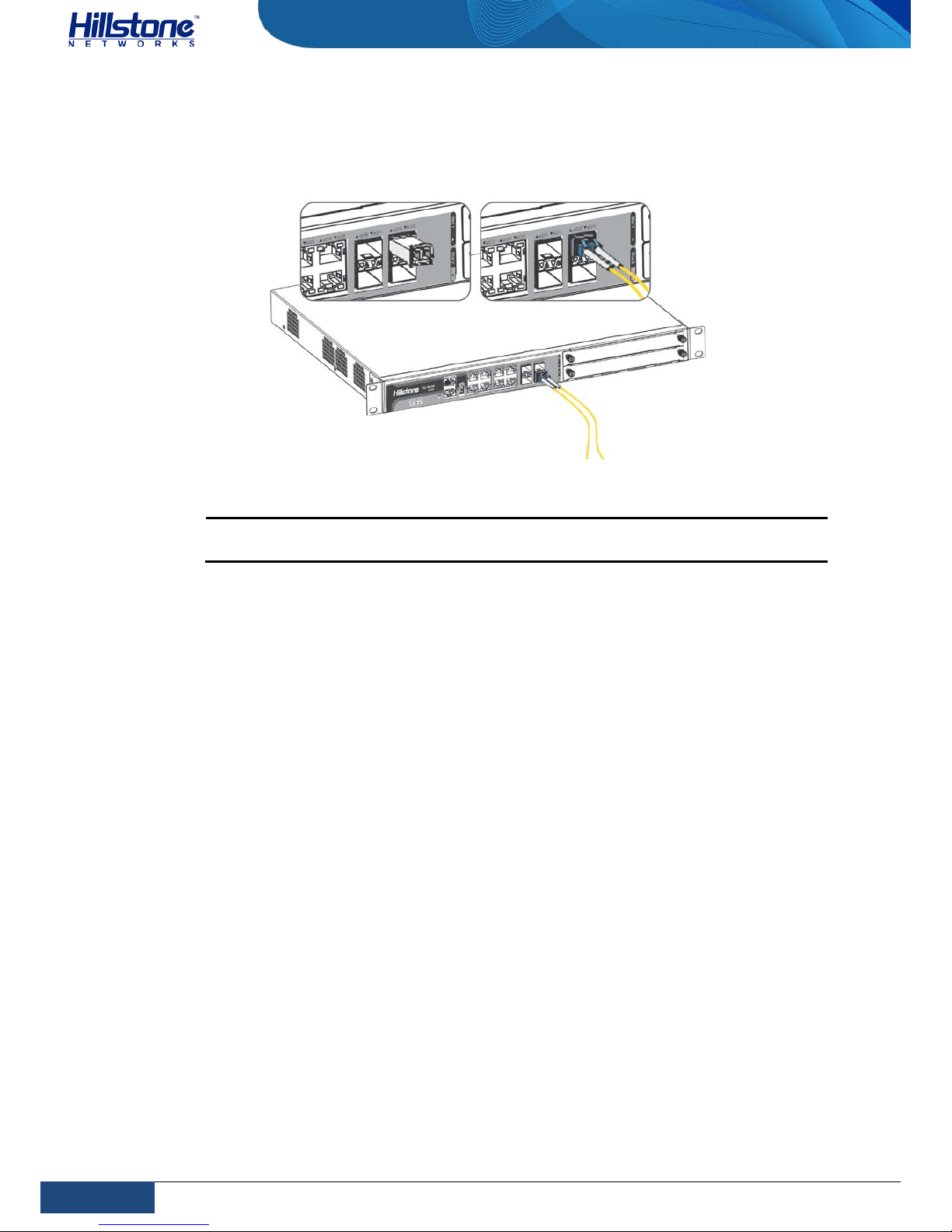
Figure 3-7: Connecting the E thernet Fiber Cable
Warning: Laser danger! To protect your eyes from radiation harm, do not stare
into a cable connector connected to a laser generator.
Connecting an AC Power Cable
The AC power cable is shipped with the chassis. Prepare a single-phase threeterminal power socket with a ground contact in advanc e. Normally, the ground
contact of the power supply system in a building was buried during construction
and cabling. Before connecting the AC input power cable, you must make sure that
the power socket is well grounded.
To connect the AC power cable, take the following s teps:
1. Make sure the ground wire is reliably connected to the earth ground.
2. Make sure the power switch of the device is in the OFF position.
3. Connect the AC power socket of the power source using the AC power cable.
To connect more cables, repeat this step.
4. Power on the switch of the device.
5. Check PWR LED on the front panel. A shining LED indicates correct connection.
Page 43
36
Chapter 3 Installation | Hillstone
Hillstone SG-6000 E-Series Hardware Reference Guide
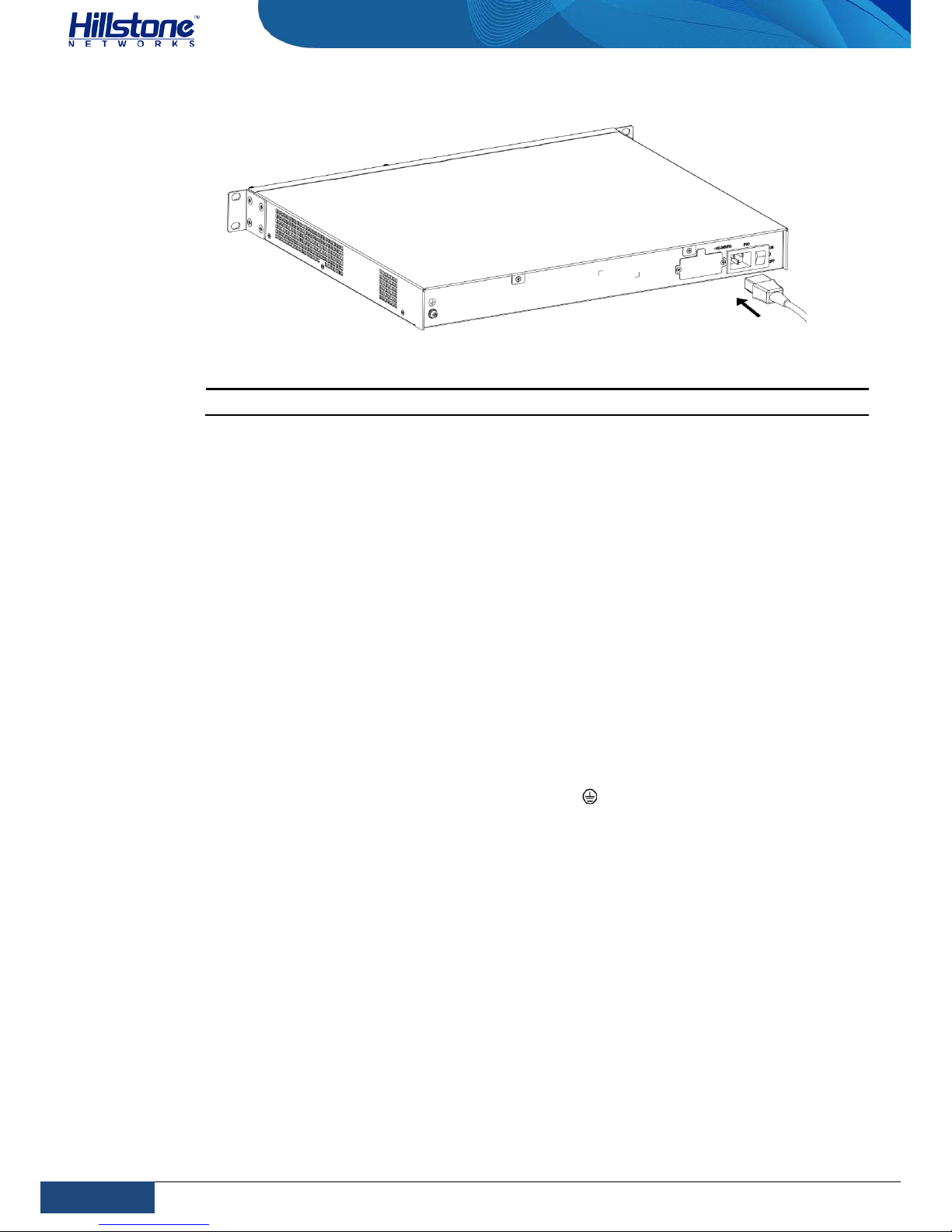
Figure 3-8: Connecting an AC Power Cable
Note: If a product does not have a power switch, you can skip Step2 and Step4.
Connecting a DC Power Cable
To power the device with DC power source, use DC power cables to connect the
device and the external DC power source.
Warning: Before performing the procedure, ensure that the cable is not connected
with any power source and make sure the cables will not be powered on during the
process.
To connect the DC power cable to the device, take the following steps:
1. Ensure that the power source voltage is in accordance with required voltage
specified in System Parameters.
2. Switch off the power source.
3. If the terminal on the power supply module has a plastic cover, remove the
cover and keep it.
4. Connect the grounding screw (labeled with “ ”) to the ground contact point
using a grounding wire.
5. Use DC cables to connect the “+” terminal of the device to the “+” terminal
of the power source, and “-” terminal to the “-” terminal of the source.
6. Verify the connection is correct and fasten the cables using a screwdriver.
7. Recover the plastic cover(s) to the original terminal(s).
8. To connect more DC power cables, repeat Step3 to Step7.
9. Switch on the power supply module.
10. Switch on the power source and check if the PWR LED is on. A shining LED
indicates correct connection.
Page 44
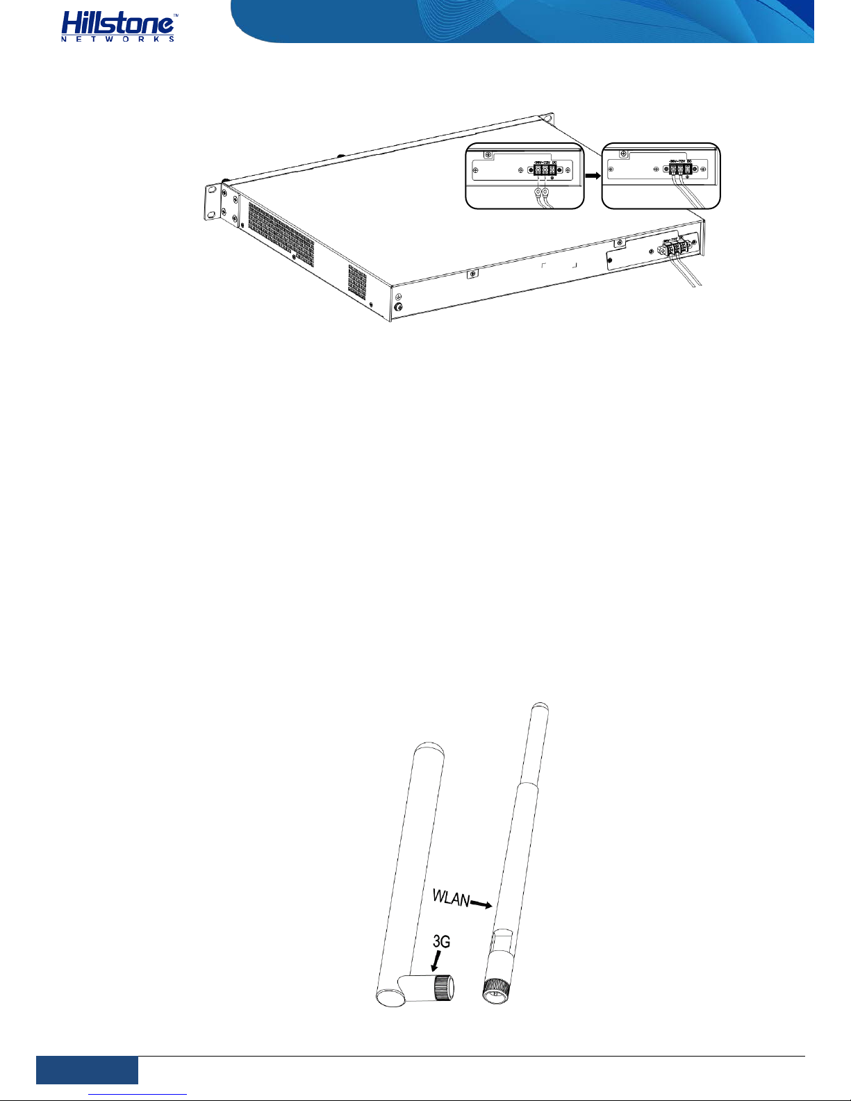
37
Chapter 3 Installation | Hillstone
Hillstone SG-6000 E-Series Hardware Reference Guide
Figure 3-9: Connecting a DC Pow er Cable
Connecting a Power Adapter
To provide the power supply, connect the power adapter of the devices with the
external AC power supply as follows:
1. Insert the DC output plug of the power adapter into the AC power interface at
the back panel of the device.
2. Connect the power adapter to the external AC power supply.
Installing an Antenna
To use the WLAN function or the 3G function of the device, you must install the
WLAN antenna or the 3G antenna. You can adjust the angle of the WLAN antenna
by rotating it. The ang le of the 3G antenna is fixed. The antennas are shown as
below:
Figure 3-10: 3G Antenna and WLAN Antenna
Page 45
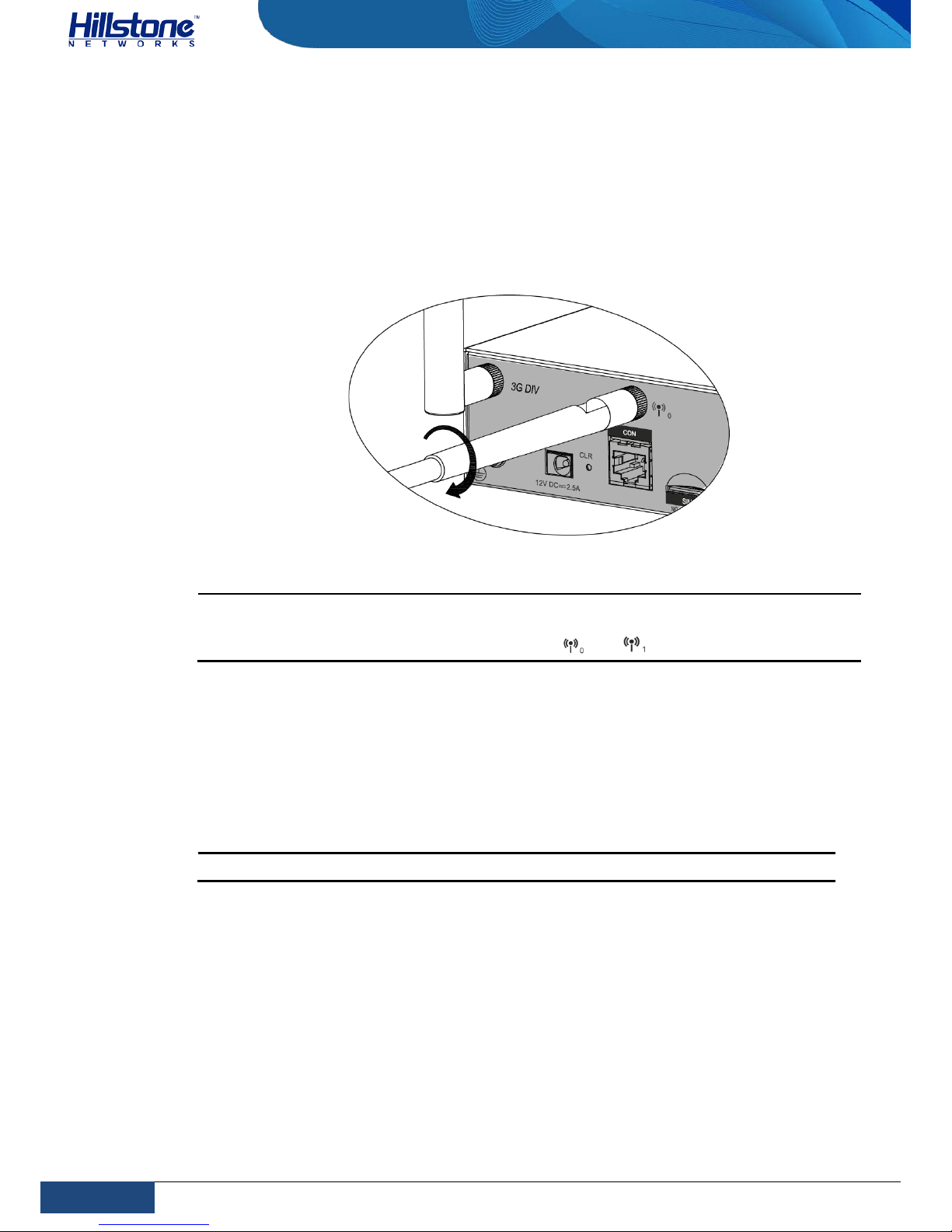
38
Chapter 3 Installation | Hillstone
Hillstone SG-6000 E-Series Hardware Reference Guide
To install antennas for SG-6000-E1100 (WLAN version) or SG-6000-E1100
(WLAN+3G version), take the following steps:
1. According to the function you use, select the corresponding antenna.
2. Install the antenna to the SMA connector at the back panel of the device by
rotating the antenna clockwise.
Figure 3-11: Antenna Installation Illustration
Note: Each type of antenna must be installed into the corresponding SMA connector.
The 3G antenna must be installed into the connect or of 3GDIV and 3GMAIN. The WLAN
antenna must be installed into the connector o f and .
Installing the SIM Card
To install the SIM card for SG-6000-E1100 (WLAN+3G version), take the following
steps:
1. Purchase the SIM card from the ISP and activate the data connection service.
2. Insert the SIM card into the SIM card slot at the back panel of the device.
Note: 3G data card and SIM card must match the network type.
Verifying Installation
After you complete the installation with all the above steps, you still need to verify
the following items.
♦ All the cables are properly connected.
♦ The grounding wire of the device is correctly connected.
♦ The air vents on both side panel of the device are unblocked, and there is
enough space around for heat dissipation.
Page 46

39
Chapter 3 Installation | Hillstone
Hillstone SG-6000 E-Series Hardware Reference Guide
♦ The expansion modules, power supply modules and fan tray are correctly
installed (for some products).
♦ The power source meets the requirements of the device.
♦ If the device is rack-mounted, make sure the rack is stable enough. If the
device is placed on a workbench, make sure the workbench is stable and
clean.
Page 47
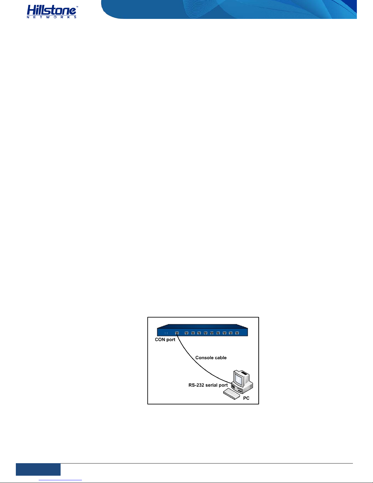
40
Chapter 4 Boot and Configuration | Hillstone
Hillstone SG-6000 E-Series Hardware Reference Guide
Chapter 4 Boot and Configuration
Introduction
This ch apter describes the initial s ystem boot and basic configuration of Hillstone
SG-6000 series, using a PC as the console terminal.
Establishing a Configuration Environm e nt
Hillstone devices support both local and remote configuration. Administrators can
use the following configuration methods.
♦ Console (CON) connection
♦ WebUI
♦ Telnet or SSH
Console (CON) Connection
For initial system configuration, you have to establish a Console connectio n
environment (connect the device to a configuration terminal through its Console
port).
To connect the PC to the CON port of the device, take following steps:
1. Set up a local configuration environmen t . Connect the Console port to the
serial port of a PC through a console cable, as shown in Figure 4-1:
Figure 4-1: Console Port Configuration
2. Run the terminal emulation program on the PC (e.g. hyper terminal of
Windows XP/Windows 2000) to set up a connection. Set the parameters of the
Page 48
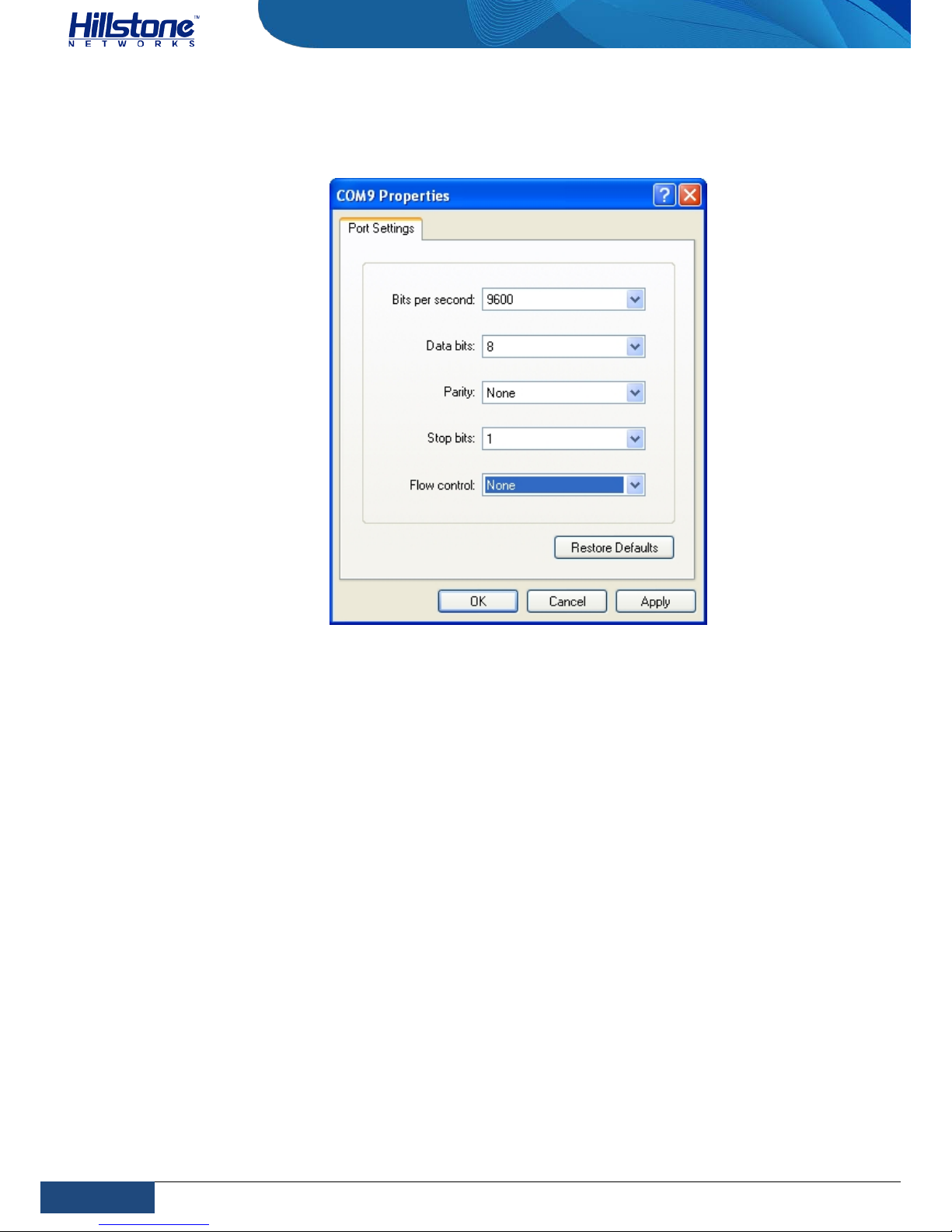
41
Chapter 4 Boot and Configuration | Hillstone
Hillstone SG-6000 E-Series Hardware Reference Guide
terminal session to 9600bps, 8 data bits, 1 stop bit, none parity, and none
flow control, as shown in Figure 4-2:
Figure 4-2: Setting Parameters for the Terminal Session
3. Switch on the power supply, and the device p er f or m s self-test and initializes
the configuration automatically. If the booting succeeds, the system will
display the command line prompt “login”. Enter the default administrator
name and password “hillstone” at the “login” and “password” prompts, press
“Enter”. And now you are successfully logged in and accessing the CLI.
4. Enter commands to configure or view running status. Enter a question mark
“?” to get help on commands whenever you want.
WebUI
The ethernet0/0 (e0/0) port has a default IP address of 192.168.1.1/24, and all the
management functions of this port are enabled by d efault. Administrators can
access the WebUI through e0/0.
To log in the device’s WebUI, take the following steps:
1. Set up the IP address of the management PC on the same subnet as
192.168.1.1/24. Connect the management PC to the e0/0 port through an
Ethernet cable.
2. Launch a Web browser of the management PC, enter the URL
http://192.168.1.1 in the address bar, and then press Enter.
Page 49

42
Chapter 4 Boot and Configuration | Hillstone
Hillstone SG-6000 E-Series Hardware Reference Guide
3. Enter the default administrator name and password “hillstone” in both the
Login and Password text boxes.
4. Click the Login button to enter WebUI main page. Then you can set o the r
configurations to the device.
Tenet and SSH
You can also establish Telnet and SSH configuration environments. For more
information, please see StoneOS User Manual.
Basic Configuration
Before you begin to use the device, you should be familiar with its features and
your network deployment. Different device position in the network requires
different topology design, working mode a nd policy configuration.
The basic configuratio ns may include:
1. Create security zones, including the link layer (L2) and network layer (L3).
Bind different interfaces to correct security zones respectively.
2. Assign IP addresses to interfaces.
3. Configure the management functions of the interfaces and create the security
policy rules.
4. Assign proper network addresses and configure the NAT rules as needed.
5. Keep network connectivity by configuring routes.
6. Configure security policy rules between security zones.
7. Configure network parameters, such as DHCP and DNS agent, etc.
For more information, see StoneOS User Manual.
Page 50
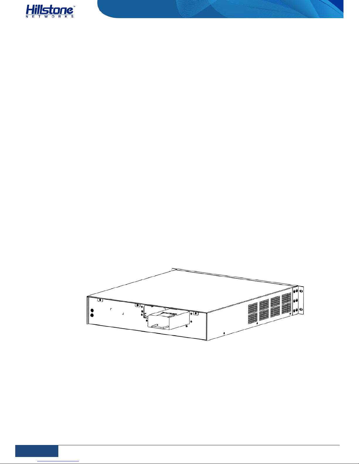
43
Chapter 5 Hardware Maintenance and Replacement | Hillstone
Hillstone SG-6000 E-Series Hardware Reference Guide
Chapter 5 Hardware Maintenance and Replacement
Introduction
This chapter explains how to install and remove the power supply module, the
expansion module and the fan tray.
Installing and Removing the Power Supply Module
This section describes how to install and remove the power supply module of SG6000-E3965, SG-6000-E5260, SG-6000-E5560, SG-6000-E5660, SG-6000-E5760,
SG-6000-E5960, SG-6000-E6160 and SG-6000-E6360. Take the following steps to
install or remove the power supply module:
To install a power supply module, take the following steps:
1. Ensure that the power supply module to be used is not connected to any
power source.
2. Face the back panel of the device.
3. If the power supply slot is covered by blank plate, remove the plate first
(unscrew the screws on the blank plate and take it down). Skip this step if the
slot is not covered.
4. Slide the power supply module all the way into the slot cage until you feel
resistant.
Figure 5-1: Installing Power Supply Module
To remove the power supply module:
1. Make sure the power supply module to be used is not connected to any supply
source.
2. Face the back panel of the device.
3. Pull the power supply straight out of the chassis using the provided handle.
Page 51

44
Chapter 5 Hardware Maintenance and Replacement | Hillstone
Hillstone SG-6000 E-Series Hardware Reference Guide
Installing and Removing the Expansion Module
SG-6000-E6360, SG-6000-E6160, SG-6000-E5960, SG-6000-E5760, SG-6000E5660, SG-6000-E5560, SG-6000-E5260, SG-6000-E3965, SG-6000-E3960, SG6000-E3662, SG-6000-E3660 and SG-6000-E2860 can accommodate expansion
modules. This section describes how to install and remove the expansion module.
To install an expansion module:
1. Make sure the power is switched off and you should wear the ESD strap
properly.
2. Face the front panel of the device.
3. Remove the blank plate on the expansion slot if necessary.
4. Slide the expansion module to be used into the slot until you feel resistant.
5. Tighten the screws on the expansion module.
To remove an expansion module:
1. Make sure the power is switched off and you should wear the ESD strap
properly.
2. Face the front panel of the device.
3. Loosen the screws on the expansion module.
4. Pull the expansion module straight out of the chassis by holding the screws.
Note: Apply a blank plate to cover the slot where no expansion module is installed.
Installing and Removing the Fan Tray
SG-6000-E6360, SG-6000-E6160, SG-6000-E5960, SG-6000-E5760, SG-6000E5660, SG-6000-E5560, SG-6000-E5260 and SG-6000-E3965 are designed with
hot-swappable fan trays.
To install a fan tray:
1. Hold the fan tray and insert it straight into the chassis until you feel resistant.
2. Tighten the screws on the fan tray.
Note: Check the FAN LED indicator when the device is powered on. A constant green
shining light indicates that the fan is functioni ng normally.
To remove a fan tray:
1. Loosen the screws on the fan tray.
2. Pull the fan tray out of the chassis by holding the provided handle.
Note: To avoid over-heating, insert a replacement fan tray immediately after
removing the existing one.
Page 52
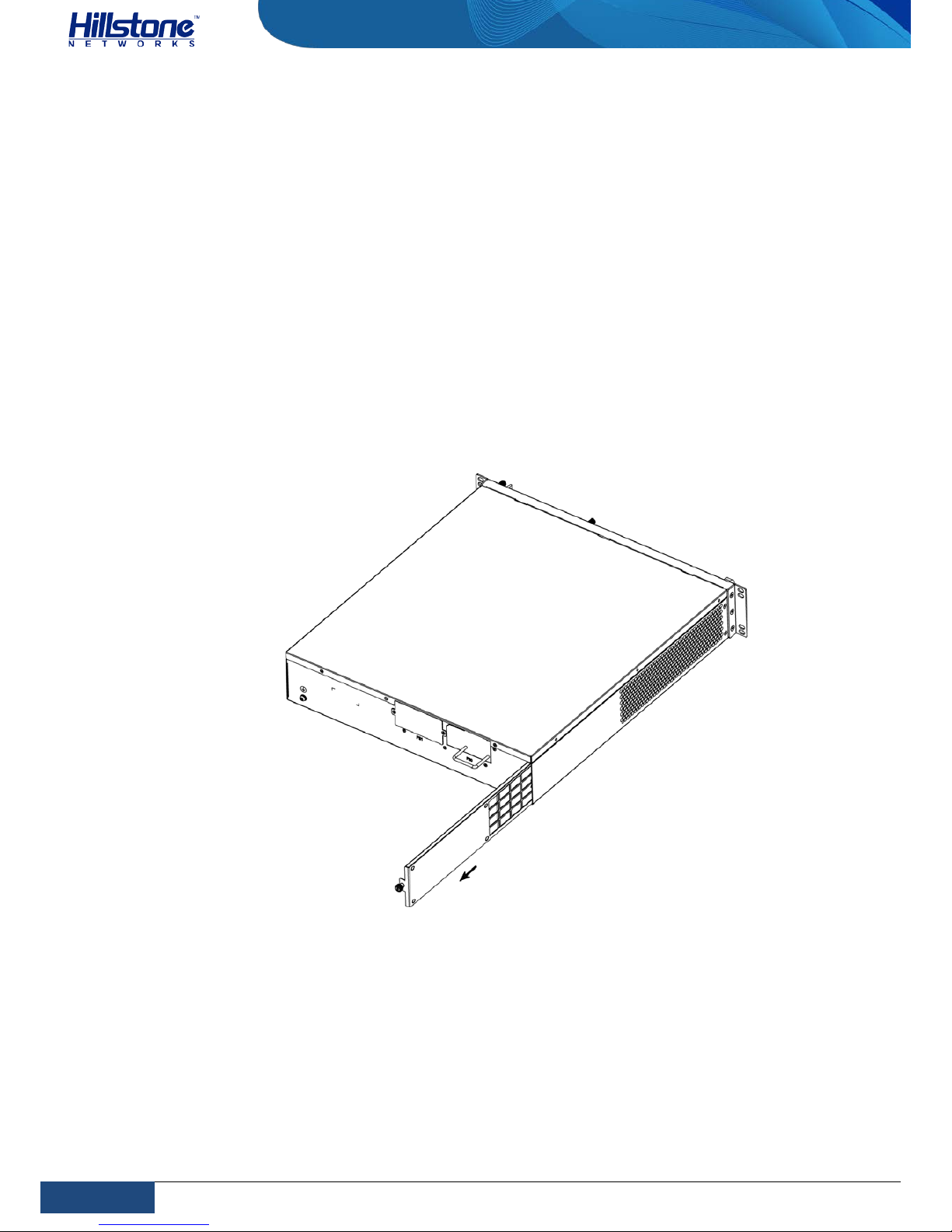
45
Chapter 5 Hardware Maintenance and Replacement | Hillstone
Hillstone SG-6000 E-Series Hardware Reference Guide
Installing and Removing the Anti-dust Mesh
SG-6000-E6360, SG-6000-E6160, SG-6000-E5560, SG-6000-E5260, SG-6000E3965 are designed with anti-dust mesh. This section describes the installation and
remove of anti-dust mesh. The anti-dust mesh is hot-swappable.
Take the following steps to install the anti-dust mesh:
1. Hold the screws of the anti-dust mesh and slide the anti-dust mesh into the
slot cage until you feel resistant.
2. Tighten the screws on the anti-dust mesh.
Take the following steps to remove the anti-dust mesh:
1. Loosen the screws.
2. Hold the screws and pull the anti-dust mesh straight out of the chassis.
Figure 5-2: Pulling An t i-dust Mesh Out
Page 53

46
Chapter 6 Troubleshooting | Hillstone
Hillstone SG-6000 E-Series Hardware Reference Guide
Chapter 6 Troubleshooting
Introduction
This chapter provides solutions to some common problems of Hillstone devices.
Losing the Administrator Password
If you lose the administrator password, please contact your local sales
representative.
Troubleshooting Power System
Check the PWR LED on the f ront panel of the device. If the power supply is
functioning normally, the PWR LED lights stead il y in green color. If the LED is off,
perform the following steps:
♦ Make sure the power supply cable is connected correctly.
♦ Ensure that the voltage of the power source conforms to the required voltage.
For the PWR LED information, see LED Indicators
.
Troubleshooting the Configuration System
The Console configur ation terminal shows sy stem booting message when the device
is powered on. If the configuration s ystem has failed, it displays error information
or nothing at all.
If the configuration terminal shows no information, perform the followin g steps:
♦ Make sure the power supply is correctly connec ted and powered on.
♦ Verify the Console cable is connected properly.
♦ Ensure the terminal co nfiguration settings are correct.
If above steps reveal no error, the Console cable may be broken.
Page 54

47
Addendum FCC Statement | Hillstone
Hillstone SG-6000 E-Series Hardware Reference Guide
Addendum FCC Statement
Warning: This is a class A product. In a domestic environment this product may
cause radio interference in which case the user may be required to take adequate
measures.
FCC Statement:
This device complies with Part 15 of the FCC Rules. O peration is subject to the
following two conditions: (1) this device may not cause harmful interference, and (2)
this device must accept any interference received, including interference that may
cause undesired operation.
Caution: The user is cautioned that changes or modifications not expressly
approved by the party responsible for compliance could void the user's authority to
operate the equipment.
Note: This equipment has been tested and found to comply with the limits for a
Class B digital device, pursuant to part 15 of the FCC Rules. These limits are
designed to provide reasonable protection against ha rmful interference in a
residential installation. This equipment ge nerates, uses and can radiate radio
frequency energy and, if not, however, there is no guarantee that interference will
not occur in a particular inst allation. If this equipment does cause har mful
interference to radio or television reception, which can be determined by turning
the equipment off and on, the user is encouraged to try to correct the interference
by one or more of the following measures:
—Reorient or relocate the receiving antenna.
—Increase the separation between the equipment and receiver.
—Connect the equipment into an outlet on a circuit different from that to which the
receiver is connected.
—Consult the dealer or an experienced radio/TV technician for help.
Page 55

48
Addendum FCC Statement | Hillstone
Hillstone SG-6000 E-Series Hardware Reference Guide
This equipment complies with FCC RF radiation exposure limits set forth for an
uncontrolled environment. This transmitter m u st not be co-located or operating in
conjunction with any o t her antenna or transm itter.
RF Exposure: A distance of 20 cm shall be maintained b etween the antenna and
users, and the transmitter may not be co-located with any othe r transmitter or
antenna.
2.4GHz Band List:
DTS (2400-2483.5 MHz)
5GHz Band List:
UNII-1 (5150-5250 MHz)
Industry Canada Statement:
This device complies with RSS-210 of the Industry C anada Rules. Operation is
subject to the following two conditions: 1) this device may not cause interference
and 2) this device must accept any interference, including interference that may
cause undesired operation of the device.
This class B digital apparatus complies with Canad ian ICES-003
IC Radiation Exposure Statement: This equipment c omplies with IC radiation
exposure limits set forth for an uncontrolled en vironment.
Avis d’Industrie Canada:
Cet appareil est conforme à la norme CNR-210 des règlements d’Industrie Canada.
Son fonctionnement est sujet aux deux conditions s uivantes: 1) Cet appareil ne doit
pas provoquer d’interférences et 2) Cet a p pareil doit accepter toutes les
interférences, y compris celles pouvant entraîner son dysfonctionnement. Cet
appareil numérique de la classe B est conforme à la norme NMB-003 du Canada
Avis d’Industrie Canada sur l’exposition aux Rayonnements: Cet appareil est
conforme aux limites d ’exposition aux rayonnem ents d’Industrie Canad a pour un
environnement non contrôlé.
European notice
The equipment named above is confirmed to comply with the requirements set out
in the Council Directive on the Approximation of the Laws of the Member States
Page 56

49
Addendum FCC Statement | Hillstone
Hillstone SG-6000 E-Series Hardware Reference Guide
relating to Electromagnetic Compatibility (2004/108/EC), Low-volt ag e Directive
(2006/95/EC) and R&TTE (1999/5/EC).
The equipment passed the test which was performed according to the following
European standards:
•ETSI EN 300 328 V1.8.1 (2012-06)
•EN 301 893 V1.7.1 (2012-06)
•EN 62311: 2008
•EN 301 908-1 V5.2.1 EN 301 908-2 V5.2.1 EN 301 511 V9.0.2
•EN 300 440-1 V1.6.1 EN 300 440-2 V1.4.1
•EN 301 489-1 V1.9.2 EN 301 489-7 V1.3.1 EN 301 489-17 V2.2.1 EN 301 489-24
V1.5.1
•EN 50383:2010
•EN 50385:2002
•EN 62311:2008
•EN 60950-1:2006 + A11:2009 + A1:2010 + A12:2011
Page 57

50
Copyright Information | Hillstone
Hillstone SG-6000 E-Series Hardware Reference Guide
Copyright Information
Copyright © 2015-2016, Hillstone Networks, lnc. All rights reserved.
Hillstone, Hillstone Networks logo, StoneOS, StoneManager, Hillstone PnPVPN, UTM Plus are
trademarks of Hi l lstone Networks.
All other trademarks or registered marks are the property of their respective owners. Hillstone
Networks assumes no responsibility for any inaccuracies in this document. Hillstone Networks
reserves the right to change, modify, transfer, or otherwise revise this publication without
notice.
Hillstone Networks Website www.hillstonenet.com
posts the latest information.
 Loading...