

Page 1

Hillstone SG-6000 T-Series Hardware
Reference Guide
www.hillstonenet.net
TW-HW-TS-EN-V2.0-Y15M03
Page 2
2
Name and Concentration of Toxic or Hazardous Substances and Elements in Products
|
Hillstone
Hillstone SG-6000 T-Series Hardware Reference Guide
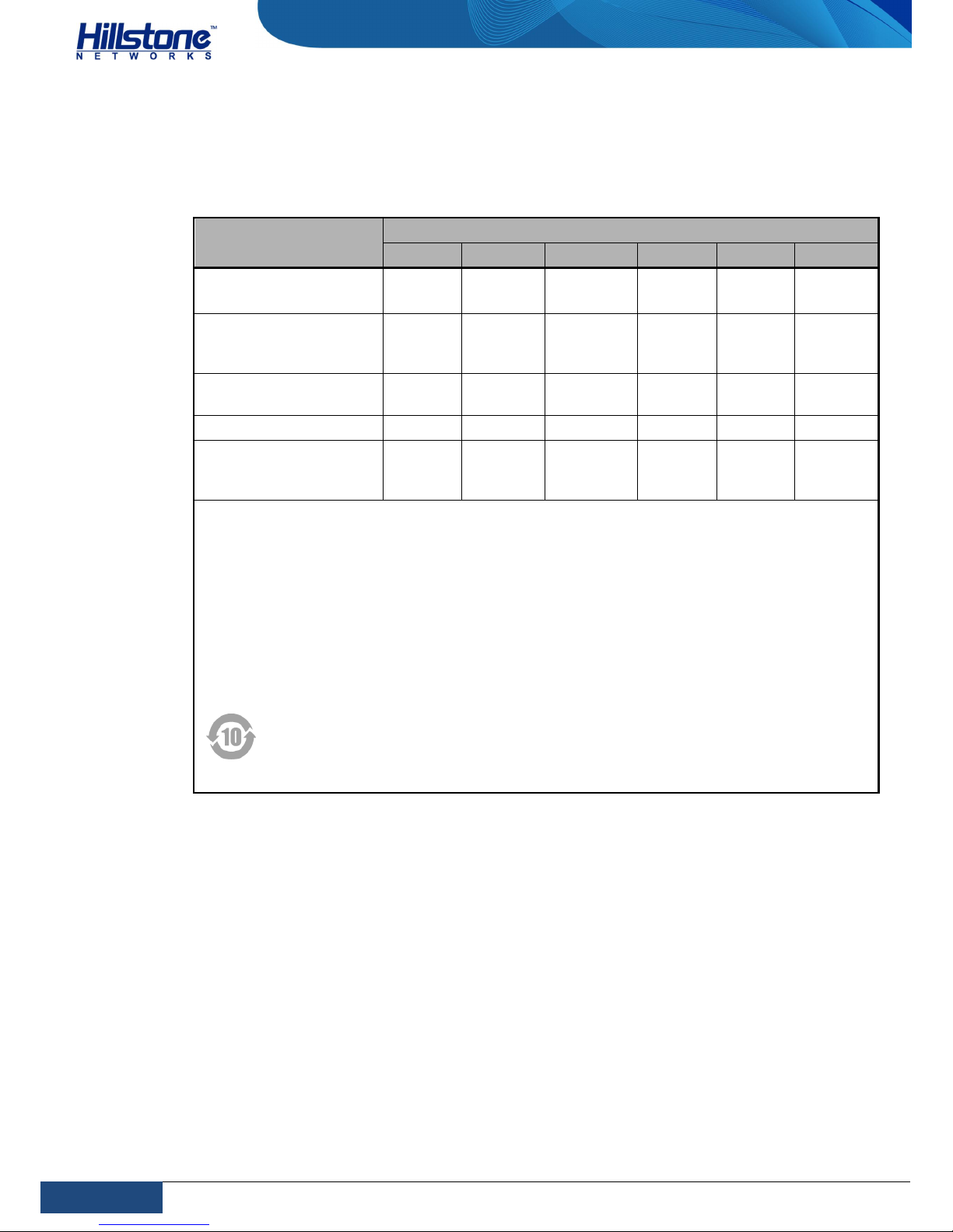
Name and Concentration of Toxic or Hazardous
Substances and Elements in Products
Component
Toxic or hazardous substances and elements
Lead Mercury Cadmium Cr6+ PBB PDBE
Metal parts
(including fasteners)
Χ O O O O O
Printed circuit board
assemblies and
components
Χ O O O O O
Cables and cable
assemblies
Χ O O O O O
Plastics and Polymers Χ O O O Χ Χ
Electric components
other than circuit
boards
Χ O O O O O
O: Indicates that this toxic or hazardous substance in the material is below the limit
requirement defined in Requirements for Concentration Limits for Certain Hazardous
Substances in Electronic Information Products (SJ/T11363-2006) issued by Ministry of
Information Industry of PRC.
Χ: Indicates that this toxic or hazardous substance in the material exceeds the limit
requirement specified in Requirements for Concentration Limits for Certain Hazardous
Substances in Electronic Information Products (SJ/T11363-2006) issued by Ministry of
Information Industry of PRC.
Note: Not all components in the table are included in one product.
This symbol indicates the environment friendly use period of all products and
components. The period applies only to the normal operation conditions specified
in this manual.
Page 3

3
Preface
|
Hillstone
Hillstone SG-6000 T-Series Hardware Reference Guide
Preface
About This Manual
Thanks for choosing the network security products from Hillstone Networks, Inc.
This document is an installation manual for Hillstone SG-6000 T-Series device to
help you install the Hillstone SG-6000 T-Series device properly.
This manual includes the following chapters:
Chapter 1. Introduction
Chapter 2. Installation Preparations
Chapter 3. Installation
Chapter 4. Boot and Configuration
Chapter 5. Hardware Maintenance and Replacement
Chapter 6. Troubleshooting
Document Conventions
This manual uses the following conventions for your convenience to read and
understand:
Warning: Indicates improper operation that may cause serious damage to
equipment or injury to operators. Thus, operators must strictly follow the
operation rules.
Caution: Indicates incorrect operation that may affect the normal use of the
equipment. Operators should be careful.
Note: Indicates information that may help readers understand the content.
Page 4

4
Table of Contents
|
Hillstone
Hillstone SG-6000 T-Series Hardware Reference Guide
Table of Contents
Chapter 1 Introduction ............................................................................................... 1
Overview ................................................................................................................ 1
Hardware Overview .................................................................................................. 1
Front Panel ........................................................................................................ 2
Back Panel......................................................................................................... 5
LED Indicators ................................................................................................... 6
Hardware Parameters ......................................................................................... 7
Interface Expansion Modules................................................................................ 8
Power Supply Modules ....................................................................................... 10
Hard Disk Modules ............................................................................................. 12
Ports ................................................................................................................ 12
Power Switch .................................................................................................... 16
CLR Button ....................................................................................................... 16
Expansion Slot .................................................................................................. 17
Cooling System ................................................................................................. 17
Chapter 2 Installation Preparations.......................................................................... 19
Introduction .......................................................................................................... 19
Installation Site Environment Requirements .............................................................. 19
Temperature/Humidity Requirements ................................................................... 19
Clearness Requirements ..................................................................................... 19
ESD Prevention ................................................................................................. 20
EMI Prevention .................................................................................................. 20
Cabinet Requirements ............................................................................................ 20
Cabinet Size and Clearance ................................................................................ 20
Ventilation Requirements ................................................................................... 20
Rack Requirements ................................................................................................ 21
Rack Size and Strength ...................................................................................... 21
Clearance Requirements ..................................................................................... 21
Connection to Building Structure ......................................................................... 21
Unpacking ............................................................................................................. 21
Chapter 3 Installation............................................................................................... 22
Installation Processes ............................................................................................. 22
Safety Requirements .............................................................................................. 22
General Safety Warnings .................................................................................... 22
Preventing ESD Damage .................................................................................... 23
Fire Safety Requirement ..................................................................................... 23
Installing the Device on a Rack or Cabinet ................................................................ 23
Installing Devices .............................................................................................. 23
Installing Interface Expansion Modules ..................................................................... 24
Installing a Hard Disk Module .................................................................................. 25
Installing a Power Supply Module ............................................................................. 26
Connecting Cables ................................................................................................. 27
Connecting the Grounding Wire ........................................................................... 27
Connecting the Console Cable ............................................................................. 28
Page 5

5
Table of Contents
|
Hillstone
Hillstone SG-6000 T-Series Hardware Reference Guide
Connecting the Ethernet/Optical Cable ................................................................. 28
Connecting the AC Power Cable ........................................................................... 30
Connecting the DC Power Cable .......................................................................... 31
Verification after Installation ................................................................................... 31
Chapter 4 Boot and Configuration ............................................................................ 32
Introduction .......................................................................................................... 32
Establishing a Configuration Environment ................................................................. 32
Console (CON) Connection .................................................................................. 32
WebUI ............................................................................................................. 33
Telnet and SSH ................................................................................................. 34
Basic Configuration ................................................................................................ 34
Chapter 5 Hardware Maintenance and Replacement ................................................. 35
Introduction .......................................................................................................... 35
General Maintenance .............................................................................................. 35
Replacing a AC Power Supply Module ....................................................................... 35
Replacing a DC Power Supply Module ....................................................................... 36
Replacing Interface Expansion Modules ..................................................................... 36
Replacing a Hard Disk Module .................................................................................. 37
Replacing a Cooling System .................................................................................... 37
Replacing a Fan Tray ......................................................................................... 38
Replacing an Anti-dust Mesh ............................................................................... 38
Chapter 6 Troubleshooting ....................................................................................... 40
Introduction .......................................................................................................... 40
Losing the Administrator Password ........................................................................... 40
Troubleshooting Expansion Modules ......................................................................... 40
Troubleshooting the Cooling System ......................................................................... 40
Troubleshooting the Power System .......................................................................... 40
Troubleshooting the Configuration System ................................................................ 41
Page 6

6
List of Figures
|
Hillstone
Hillstone SG-6000 T-Series Hardware Reference Guide
List of Figures
Figure 1: SG-6000-T5860/SG-6000-T5060 Front View .................................................. 1
Figure 2: SG-6000-T3860 Front View ......................................................................... 2
Figure 3: SG-6000-T5860/SG-6000-T5060/SG-6000-T3860 Back Panel .......................... 2
Figure 4: SG-6000-T5860 Front Panel ........................................................................ 2
Figure 5: SG-6000-T5060 Front Panel ........................................................................ 3
Figure 6: SG-6000-T3860 Front Panel ........................................................................ 4
Figure 7: SG-6000-T5860/SG-6000-T5060/SG-6000-T3860 Back Panel .......................... 5
Figure 8: Front Panel of IOC-2XFP-Lite-M .................................................................... 8
Figure 9: Front Panel of IOC-8SFP-M .......................................................................... 8
Figure 10: Front Panel of IOC-8GE-M.......................................................................... 9
Figure 11: Front Panel of IOC-4GE-B-M ...................................................................... 9
Figure 12: Front Panel of IOC-4XFP ............................................................................ 9
Figure 13: Front Panel of IOC-4SFP+ .......................................................................... 9
Figure 14: AC Power Supply Module ......................................................................... 10
Figure 15: DC Power Supply Module ......................................................................... 11
Figure 16: Fan Tray ................................................................................................ 18
Figure 17: Air Circulation ........................................................................................ 18
Figure 18: Installing Rack-mounting Ears .................................................................. 24
Figure 19: Installing the Device in a Rack ................................................................. 24
Figure 20: Removing the Blank Panel ....................................................................... 25
Figure 21: Installing the Hard Disk Module ................................................................ 25
Figure 22: Installing the Blank Panel ........................................................................ 26
Figure 23: Installing the Power Supply Module........................................................... 27
Figure 24: Grounding Screw .................................................................................... 27
Figure 25: Connecting the Ethernet Copper Cable ...................................................... 29
Figure 26: Connecting the Ethernet Copper Cable ...................................................... 30
Figure 27: Connecting an AC Power Cable ................................................................. 30
Figure 28: Console Port Configuration ...................................................................... 32
Figure 29: Setting Parameters for the Terminal Session .............................................. 33
Figure 30: Replacing an Expansion Module ................................................................ 37
Figure 31: Removing the Fan Tray ........................................................................... 38
Page 7

7
List of Tables
|
Hillstone
Hillstone SG-6000 T-Series Hardware Reference Guide
List of Tables
Table 1: SG-6000-T5860 Front Panel Description ......................................................... 3
Table 2: SG-6000-T5060 Front Panel Description ......................................................... 4
Table 3: SG-6000-T3860 Front Panel Description ......................................................... 5
Table 4: SG-6000-T5860/SG-6000-T5060/SG-6000-T3860 Back Panel Description .......... 5
Table 5: LED Descriptions ......................................................................................... 6
Table 6: Hardware Parameters .................................................................................. 7
Table 7: Interface Expansion Modules ......................................................................... 8
Table 8: Meanings of LED indicators ......................................................................... 10
Table 9: Power Supply Module LED Descriptions ........................................................ 11
Table 10: Console Port Attributes ............................................................................. 12
Table 11: Auxiliary Port Attributes............................................................................ 12
Table 12: USB Host Port Attributes .......................................................................... 13
Table 13: SFP Port Attributes .................................................................................. 13
Table 14: SFP Optical Module Attributes.................................................................... 14
Table 15: SFP+ Port Attributes ................................................................................ 14
Table 16: SFP+ Optical Module Attributes ................................................................. 15
Table 17: XFP Optical Module Attributes.................................................................... 15
Table 18: XFP Optical Module Attributes.................................................................... 16
Table 19: Temperature and Humidity Requirements ................................................... 19
Table 20: Dust Concentration Requirements in the Equipment Room ............................ 19
Page 8
1
Chapter 1 Introduction
|
Hillstone
Hillstone SG-6000 T-Series Hardware Reference Guide
Chapter 1 Introduction
Overview
The Hillstone SG-6000 T-Series product models, which is developed by Hillstone
Networks, has the ability to perform the proactive inspection and analysis, foresee
the network risks, and perform the effective actions against the network risks. With
multi cores and parallel processing architecture and high performance CPU, the
device can implement the high efficiency processing and forwarding for the data, as
well as the deep mining and analysis. The device is suitable for internet accessing
scenario, internal network separating scenario, and front server protection scenario,
and it can provide proactive and full-ranged protection for users’ network and key
businesses, intelligently collect the key information of the users’ network and
businesses. With the comprehensive analysis of the key information, the device
examines the potential risks in users’ network and notifies the administrators to
troubleshoot potential risks, reduce the occurring rate of problems, and reduce the
damages that the risks made to the users’ network and businesses.
Currently, Hillstone SG-6000 T-Series product models includes SG-6000-T5860,
SG-6000-T5060 and SG-6000-T3860.
Hardware Overview
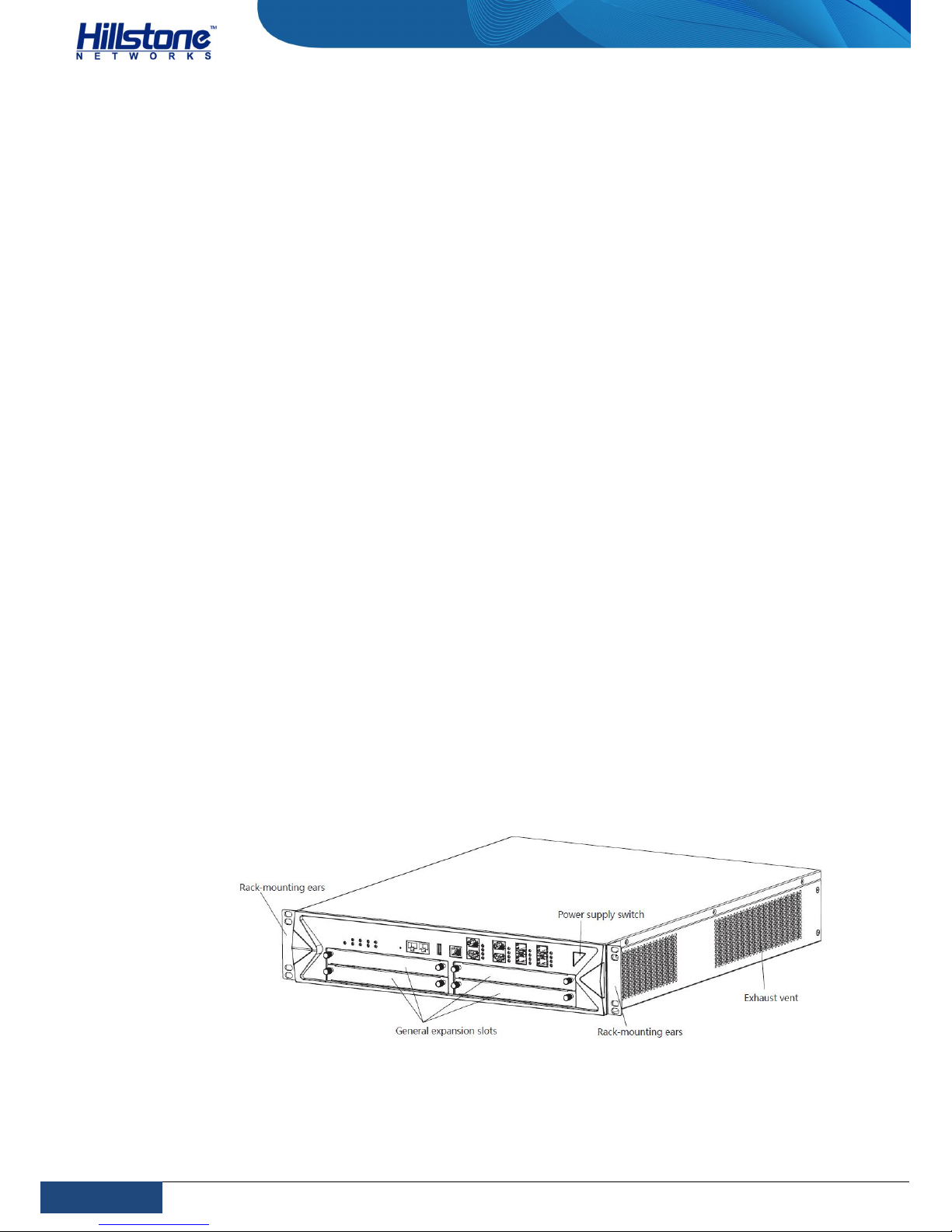
Hillstone SG-6000 T-Series device is designed to fit in standard 19-inch
cabinets/racks, and it can be installed in a standard 19-inch cabinet/rack. The
device chassis is 2U and its external dimensions is 440.0 mm high, 515.0 mm deep
and 88.4 mm wide.
Figure 1: SG-6000-T5860/SG-6000-T5060 Front View
Page 9
2
Chapter 1 Introduction
|
Hillstone
Hillstone SG-6000 T-Series Hardware Reference Guide
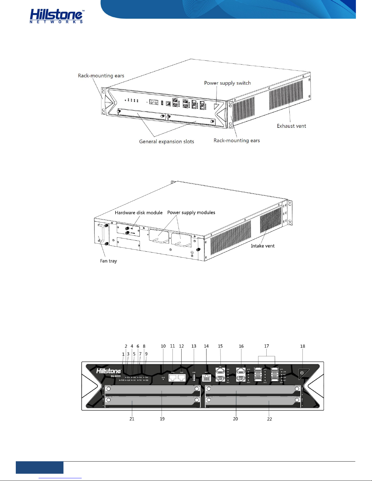
Figure 2: SG-6000-T3860 Front View
Figure 3: SG-6000-T5860/SG-6000-T5060/SG-6000-T3860 Back Panel
Front Panel
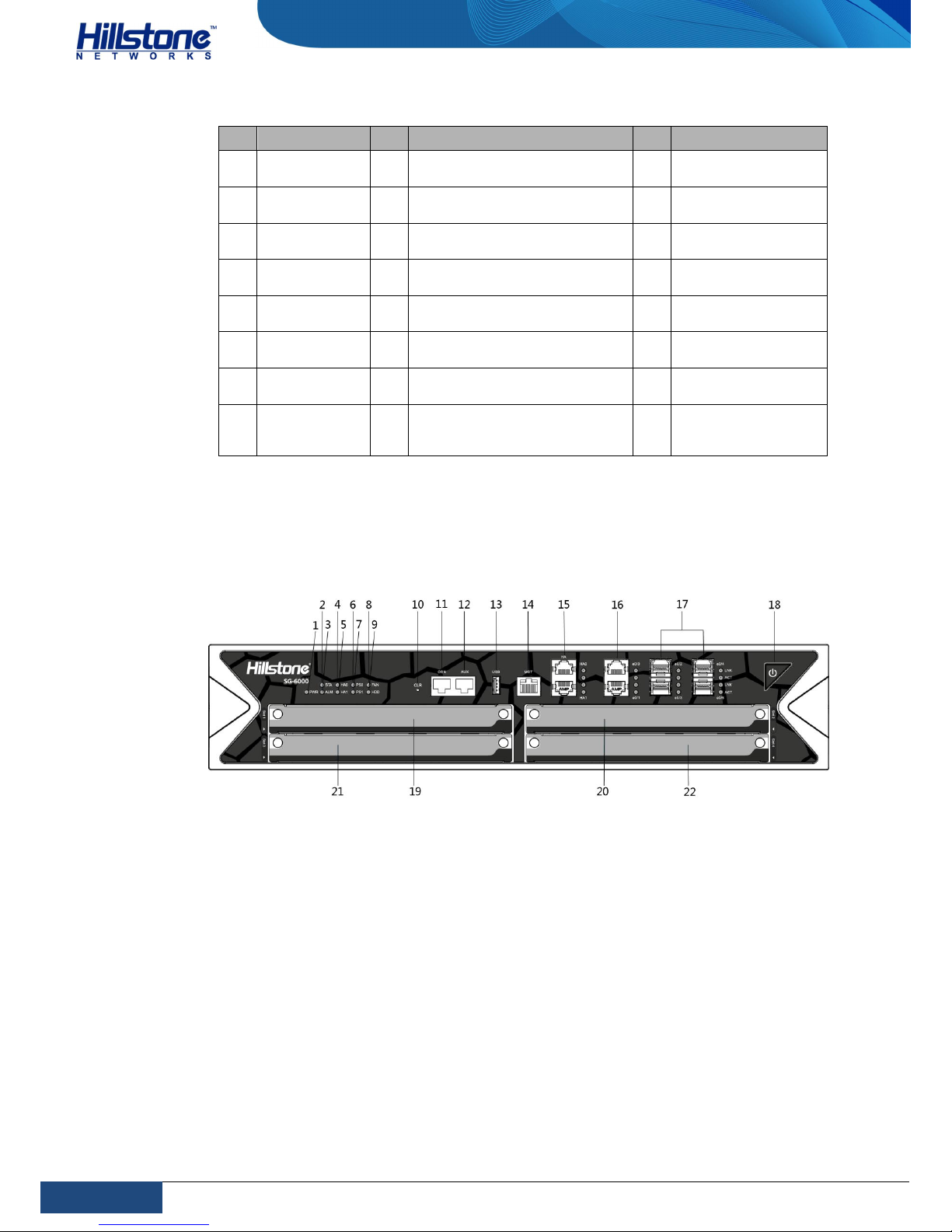
The front panel of SG-6000-T5860 consists of 1 power switch, 1 CLR button, 1
Console port, 1 Auxiliary port, 1 USB port, 1 MGT port, 2 HA ports, 2 Gigabit
Ethernet ports, 4 SFP ports, 4 expansion slots, and LED indications.
Figure 4: SG-6000-T5860 Front Panel
Page 10
3
Chapter 1 Introduction
|
Hillstone
Hillstone SG-6000 T-Series Hardware Reference Guide
Table 1: SG-6000-T5860 Front Panel Description
No. Label No. Label No. Label
1
PWR: Power
LED
9 HDD: Hard disk status 17
e0/6 - e0/9: SFP
ports
2
STA: Status
LED
10 CLR: CLR button 18 Power switch
3
ALM: Alarm
LED
11 CON: Console port 19
Slot1: Interface
expansion slot
4
HA0: HA
status0 LED
12 AUX: Auxiliary port 20
Slot2: Interface
expansion slot
5
HA1: HA
status1 LED
13
USB: USB port
21
Slot3: Interface
expansion slot
6
PS0: Power
PS0 LED
14
MGT: management port
22
Slot4: Interface
expansion slot
7
PS1: Power
PS1 LED
15
HA0-HA1: HA ports (not
available temporarily)
- -
8
FAN: Fan tray
LED
16
e0/0-e0/1: Gigabit Ethernet
ports
- -
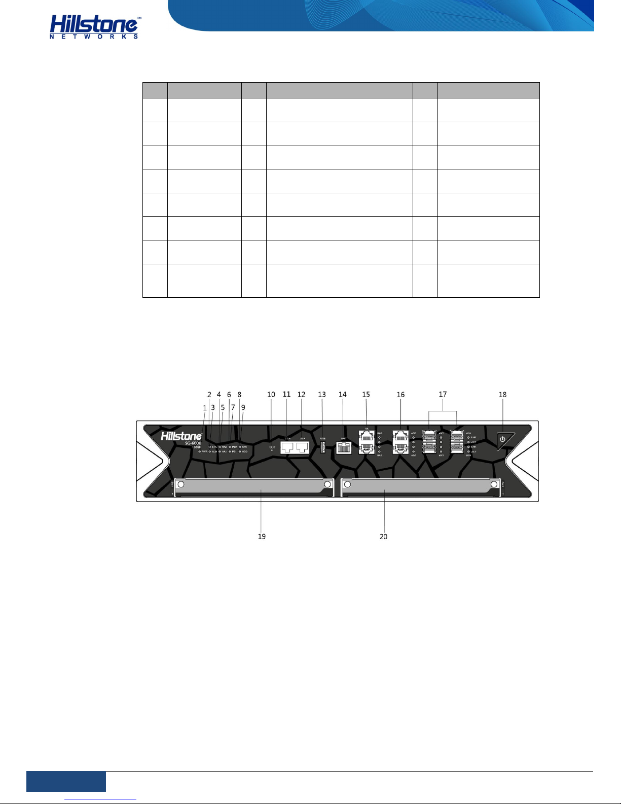
The front panel of SG-6000-T5060 consists of 1 power switch, 1 CLR button, 1
Console port, 1 Auxiliary port, 1 USB port, 1 MGT port, 2 HA ports, 2 Gigabit
Ethernet ports, 4 SFP ports, 4 expansion slots, and LED indications.
Figure 5: SG-6000-T5060 Front Panel
Page 11
4
Chapter 1 Introduction
|
Hillstone
Hillstone SG-6000 T-Series Hardware Reference Guide
Table 2: SG-6000-T5060 Front Panel Description
No. Label No. Label No. Label
1
PWR: Power
LED
9 HDD: Hard disk status 17
e0/6 - e0/9: SFP
ports
2
STA: Status
LED
10 CLR: CLR button 18 Power switch
3
ALM: Alarm
LED
11 CON: Console port 19
Slot1: Interface
expansion slot
4
HA0: HA
status0 LED
12 AUX: Auxiliary port 20
Slot2: Interface
expansion slot
5
HA1: HA
status1 LED
13
USB: USB port
21
Slot3: Interface
expansion slot
6
PS0: Power
PS0 LED
14
MGT: management port
22
Slot4: Interface
expansion slot
7
PS1: Power
PS1 LED
15
HA0-HA1: HA ports (not
available temporarily)
- -
8
FAN: Fan tray
LED
16
e0/0-e0/1: Gigabit Ethernet
ports
- -
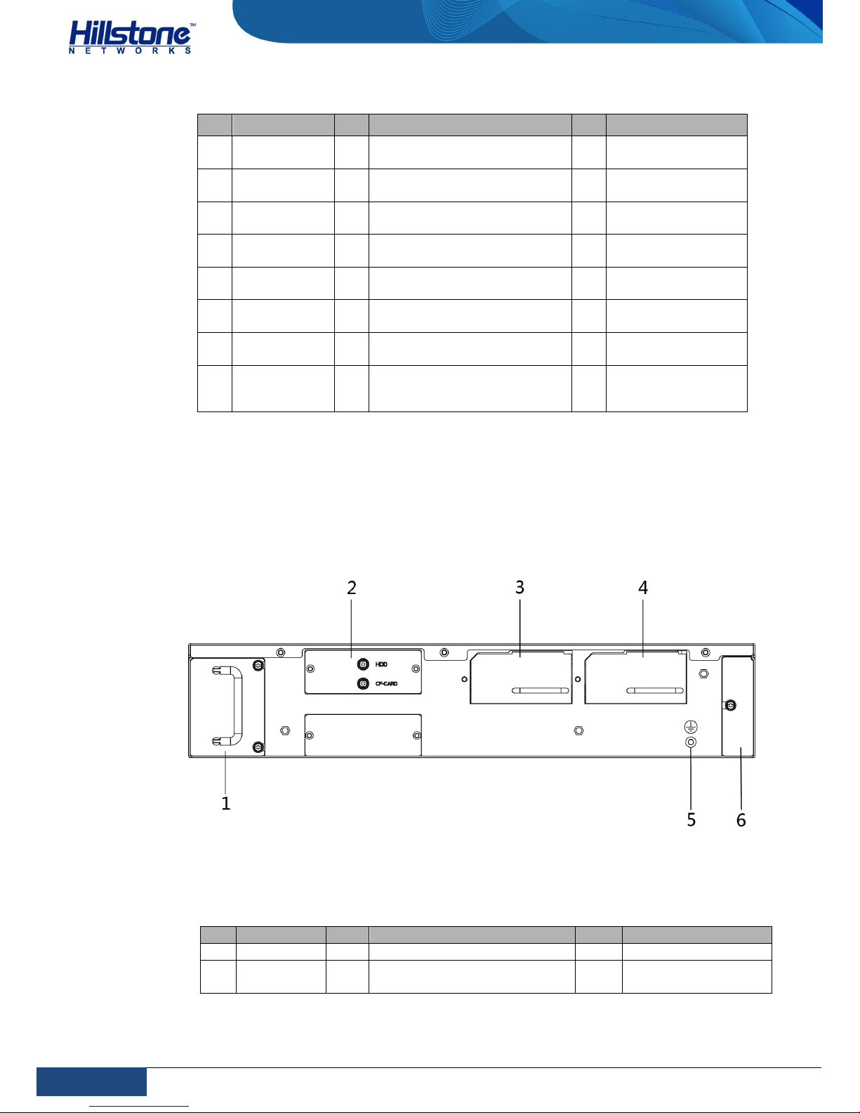
The front panel of SG-6000-T3860 consists of 1 power switch, 1 CLR button, 1
Console port, 1 Auxiliary port, 1 USB port, 1 MGT port, 2 HA ports, 2 Gigabit
Ethernet ports, 4 SFP ports, 2 expansion slots, and LED indications.
Figure 6: SG-6000-T3860 Front Panel
Page 12
5
Chapter 1 Introduction
|
Hillstone
Hillstone SG-6000 T-Series Hardware Reference Guide
Table 3: SG-6000-T3860 Front Panel Description
No. Label No. Label No. Label
1
PWR: Power
LED
9 HDD: Hard disk status 17
e0/6 - e0/9: SFP
ports
2
STA: Status
LED
10 CLR: CLR button 18 Power switch
3
ALM: Alarm
LED
11 CON: Console port 19
Slot1: Interface
expansion slot
4
HA0: HA
status0 LED
12 AUX: Auxiliary port 20
Slot2: Interface
expansion slot
5
HA1: HA
status1 LED
13
USB: USB port
- -
6
PS0: Power
PS0 LED
14
MGT: management port
- -
7
PS1: Power
PS1 LED
15
HA0-HA1: HA ports (not
available temporarily)
- -
8
FAN: Fan tray
LED
16
e0/0-e0/1: Gigabit Ethernet
ports
- -
Back Panel
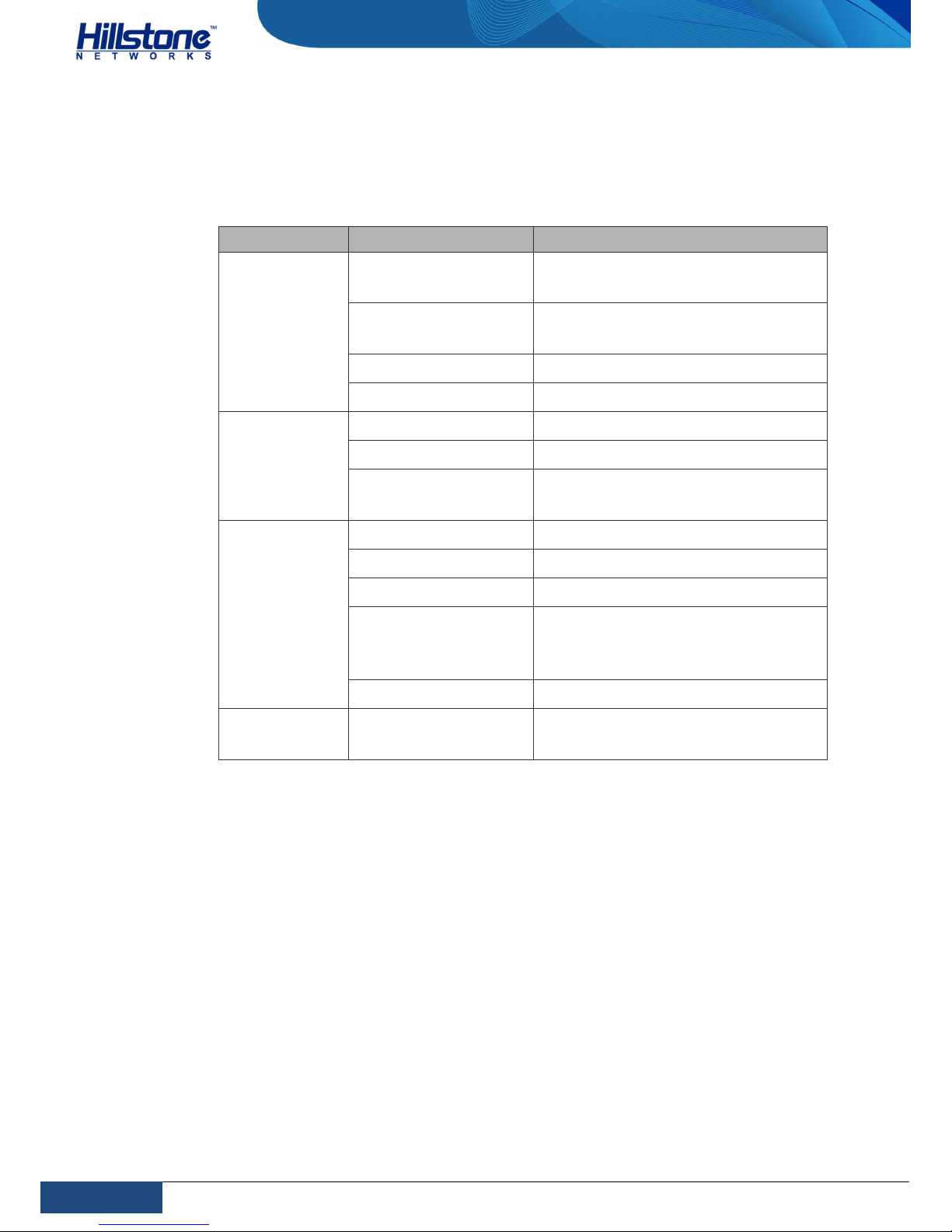
The back panels of SG-6000-T5860, SG-6000-T5060 and SG-6000-T3860 consists
of 2 sets of power supply modules, 1 hard disk module, 1 fan tray, 1 anti-dust
mesh, and 1 grounding screw.
Figure 7: SG-6000-T5860/SG-6000-T5060/SG-6000-T3860 Back Panel
Table 4: SG-6000-T5860/SG-6000-T5060/SG-6000-T3860 Back Panel
Description
No. Label No. Label No. Label
1 Fan tray 3 Power supply module PS1 5 Grounding grew
2
Hard disk
module
4 Power supply module PS0 6 Anti-dust mesh
Page 13
6
Chapter 1 Introduction
|
Hillstone
Hillstone SG-6000 T-Series Hardware Reference Guide
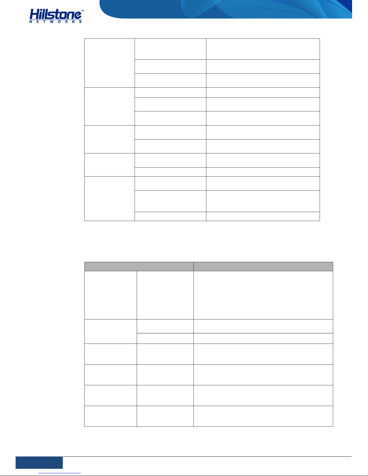
LED Indicators
The table blow describes the meanings of LED indicators on the front panels of
Hillstone SG-6000 T-Series device:
Table 5: LED Descriptions
LED Color/Status Description
PWR
Green/Always on
The device power is running
normally.
Orange/Always on
The device power is running
abnormally.
Red/Always on Power failure so the system is down.
Off The device is powered off.
STA
Green/Always on The system is booting.
Green/Blinking The system is running normally.
Red/Always on
The system has failed to boot or has
an error.
ALM
Red/Always on The system is sending alarm(s).
Green/Blinking The system is waiting.
Orange/Blinking The system is using a trial license.
Orange/Always on
The trial license has expired and
there is no legitimate license
installed in the system.
Off The system is running normally.
FAN
Green/Always on
The cooling system is running
normally.
Page 14
7
Chapter 1 Introduction
|
Hillstone
Hillstone SG-6000 T-Series Hardware Reference Guide
Orange/Always on
One of the fans on the fan tray has
failed. Change the fan tray as soon as
possible.
Red/Always on
The cooling system has a serious error
or the fan tray is not fully inserted.
Off
The circuit of the cooling system has
an error.
HDD
Green/Always on The hard disk works correctly.
Green/Blinking
The hard disk is processing data. Do
not unplug the hard disk.
Green/Off
The hard disk does not finish loading,
has errors, or is not presented.
LNK
Green/Always on
The link between this port and its peer
device is in normal status.
Off
The link between this port and its peer
device has failed.
ACT
Orange/Blinking
The link between this port and its peer
device is in normal status.
Off No data is transmitted on this port.
PS0/PS1
Green/Always on
The power supply module is running
normally.
Red/Always on
The power supply module’s fan has
failed or the standby voltage outputs
abnormally.
Off There is no power supply input.
Hardware Parameters
Table 6: Hardware Parameters
Item Description
Fixed Ports
SG-6000-T5860
SG-6000-T5060
SG-6000-T3860
1 MGT port
2 HA ports
1 USB port
1 Console port
1 Auxiliary port
2 Gigabit Ethernet port
4 SFP ports
Expansion
module
SG-6000-T5860
SG-6000-T5060
4 expansion slots
SG-6000-T3860 2 expansion slots
Memory
SG-6000-T5860
SG-6000-T5060
SG-6000-T3860
24GB
Flash Memory
SG-6000-T5860
SG-6000-T5060
SG-6000-T3860
512MB
Dimensions
(W×D×H)
SG-6000-T5860
SG-6000-T5060
SG-6000-T3860
440.0mm x 535.0mm x 88.4mm
Weight
SG-6000-T5860
SG-6000-T5060
SG-6000-T3860
Net weight: 15kg
Gross weight: 18.5kg (accessories and
packages included)
Page 15
8
Chapter 1 Introduction
|
Hillstone
Hillstone SG-6000 T-Series Hardware Reference Guide
Power Rating
SG-6000-T5860
SG-6000-T5060
SG-6000-T3860
450W x2
Input Voltage
AC: 90-264V AC, 50/60Hz
DC: -40 - -60V DC
Ambient Temperature
0℃-40℃
Relative Humidity 10%-95% (non-condensing)
Note: Memory is the random access memory to store the communication data
for the CPU. Flash Memory is used for storing the operating system firmware
and application files.
Interface Expansion Modules
Hillstone SG-6000 T-Series device has expansion slots for the interface expansion.
SG-6000-T5860 and SG-6000-T5060 support the following interface expansion
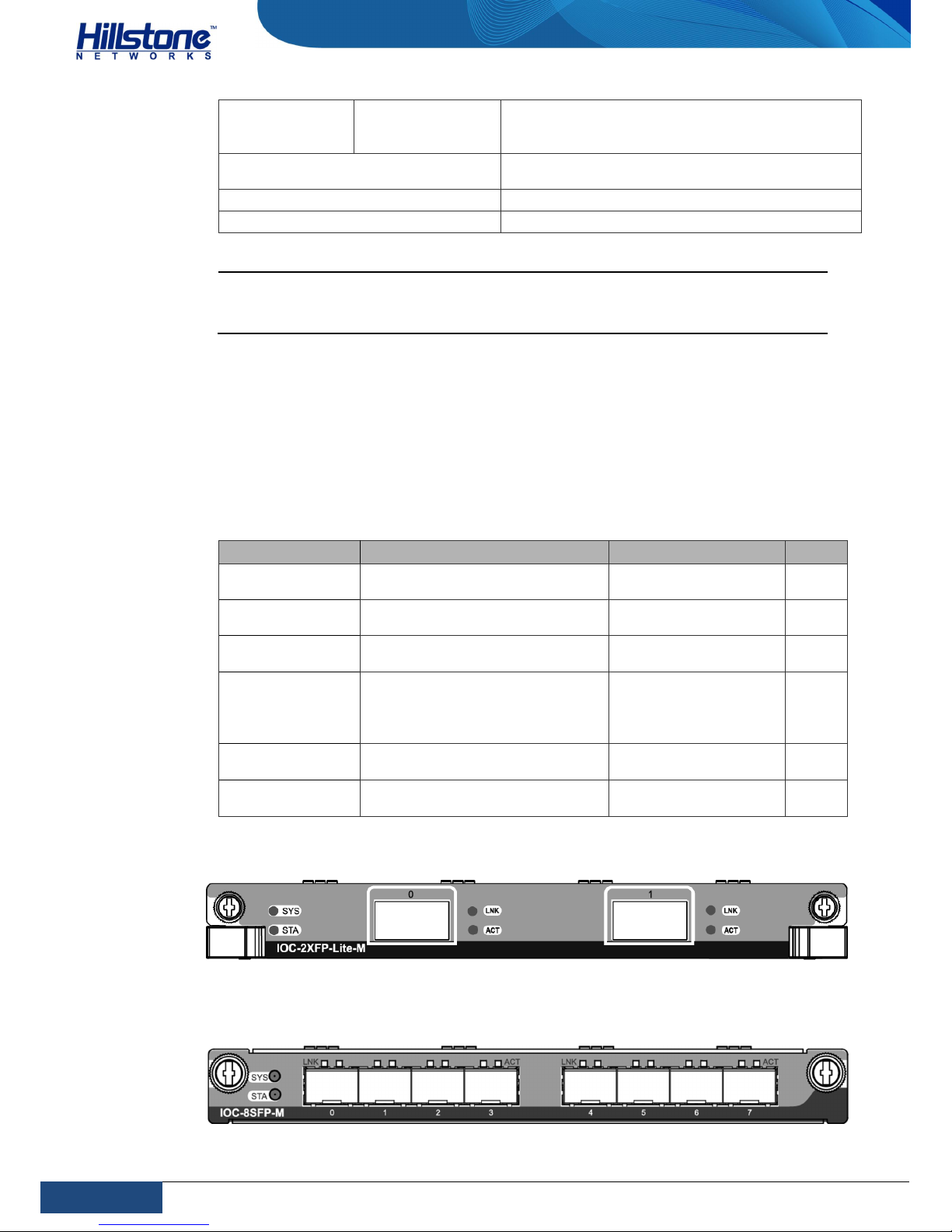
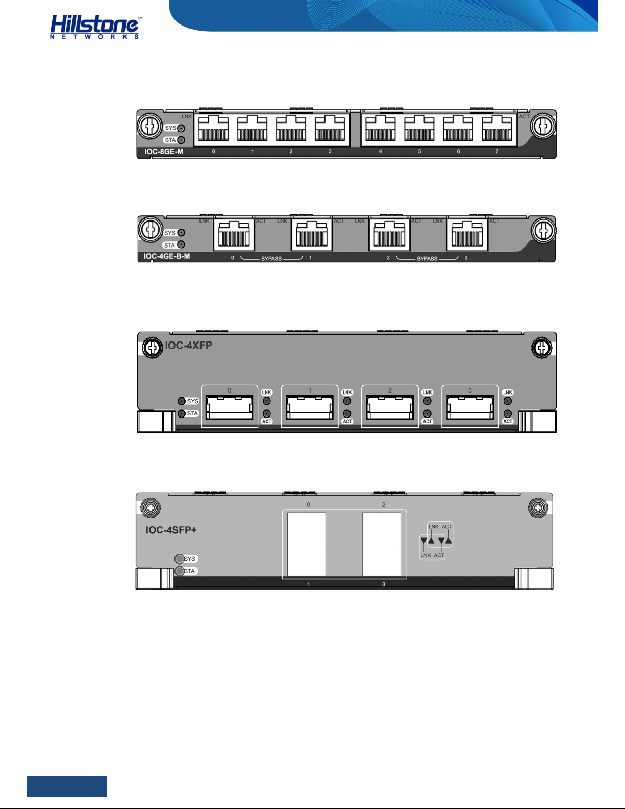
modules: IOC-4GE-B-M, IOC-8GE-M, IOC-8SFP-M, IOC-2XFP-Lite-M, and IOC-4XFP.
SG-6000-T3860 supports the following interface expansion modules: IOC-4GE-B-M,
IOC-8GE-M, IOC-8SFP-M and IOC-2XFP-Lite-M.
Table 7: Interface Expansion Modules
Name Device Type Description Size
IOC-2XFP-Lite-M
SG-6000-T5860, SG-6000T5060, and SG-6000-T3860
2 XFP ports 1/2 U
IOC-8SFP-M
SG-6000-T5860, SG-6000T5060, and SG-6000-T3860
8 SFP ports 1/2 U
IOC-8GE-M
SG-6000-T5860, SG-6000T5060, and SG-6000-T3860
8 Gigabit Ethernet
ports
1/2 U
IOC-4GE-B-M
SG-6000-T5860, SG-6000T5060, and SG-6000-T3860
4 Gigabit Ethernet
ports which can be
grouped as 2 Bypass
pairs
1/2 U
IOC-4XFP
SG-6000-T5860 and SG-6000T5060
4 XFP ports 1U
IOC-4SFP+
SG-6000-T5860 and SG-6000T5060
4 SFP+ ports 1U
Figure 8: Front Panel of IOC-2XFP-Lite-M
Figure 9: Front Panel of IOC-8SFP-M
Page 16
9
Chapter 1 Introduction
|
Hillstone
Hillstone SG-6000 T-Series Hardware Reference Guide
Figure 10: Front Panel of IOC-8GE-M
Figure 11: Front Panel of IOC-4GE-B-M
Figure 12: Front Panel of IOC-4XFP
Figure 13: Front Panel of IOC-4SFP+
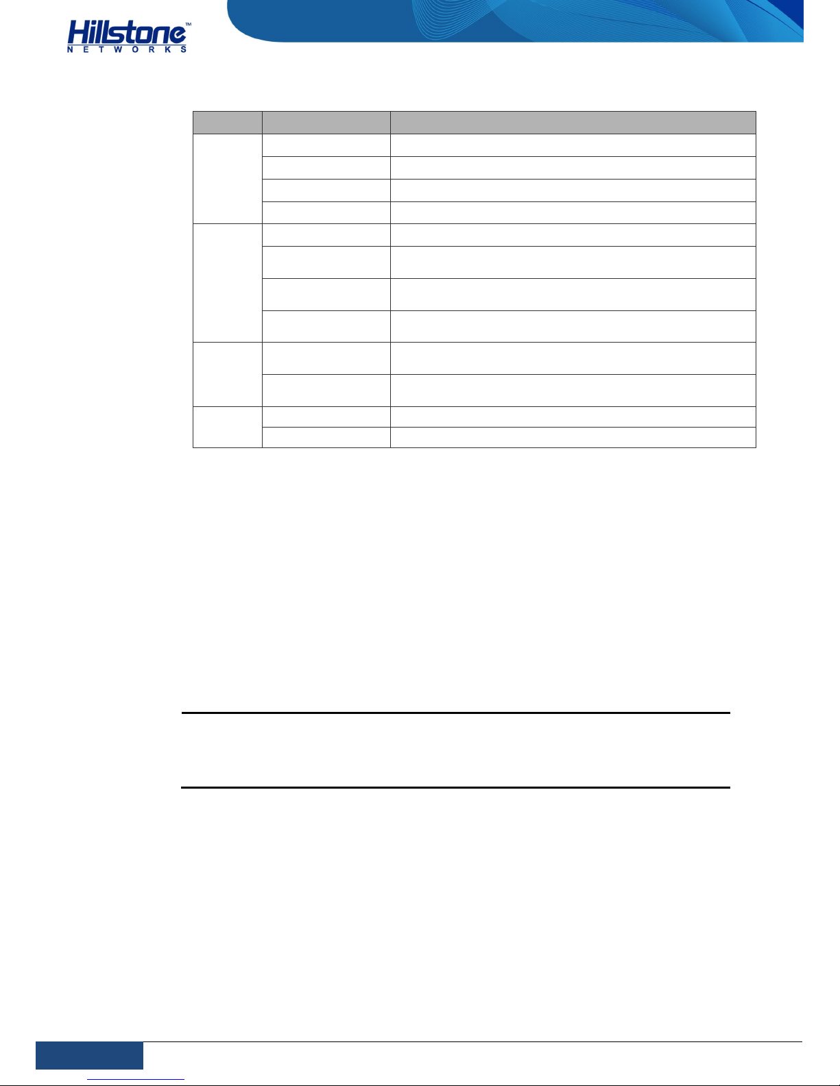
The following table describes the meanings of LED indicators on the front panels of
expansion modules.
Page 17
10
Chapter 1 Introduction
|
Hillstone
Hillstone SG-6000 T-Series Hardware Reference Guide
Table 8: Meanings of LED indicators
LED Color/Status Description
SYS
Green/Always on The expansion module is running normally.
Green/Always on The expansion module is preparing for hot plugging.
Green/Always on The expansion module has been ejected.
Off The expansion module is powered off.
STA
Green/Always on The expansion module is booting.
Green/Blinking
The expansion module has started and is normally
working.
Red/Always on
The expansion module fails to start or there is
connection error.
Off
The expansion module has failed or no module is
presented.
LNK
Green/Always on
The link between this port and its peer device is
connected and is in normal status.
Off
The link between this port and its peer device has
failed or it has no connection.
ACT
Yellow/Blinking The port is sending or receiving data.
Off No data is transmitted on this port.
Power Supply Modules
Hillstone SG-6000 T-Series device uses the 1+1 mode for power supply. One power
supply module is worked as the main one, and the other power supply is worked as
the standby power supply. When the main power supply module interrupted, the
standby power supply will be enabled instantly. This power supply mode avoids the
situation that devices stop working because of the sudden power-off and ensures
the uninterruptible power supply. When selecting the power supply line, Hillstone
suggests that you select different power supply line for each power supply module.
Install the power supply modules into the power supply expansion slots in the back
panel: PS0 and PS1.
Notes:
The standby power supply module is hot-swappable.
Hillstone suggests not using AC and DC power supply modules
meanwhile in one device.
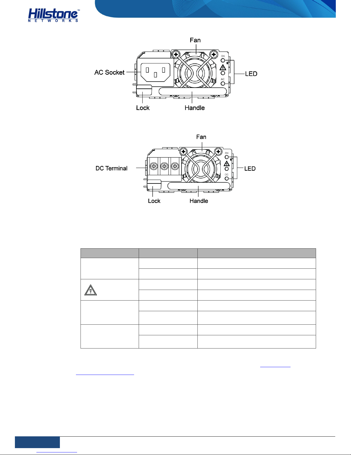
Figure 14: AC Power Supply Module
Page 18
11
Chapter 1 Introduction
|
Hillstone
Hillstone SG-6000 T-Series Hardware Reference Guide
Figure 15: DC Power Supply Module
The power supply module LED descriptions for Hillstone SG-6000 T-Series device
are listed in the following table:
Table 9: Power Supply Module LED Descriptions
LED Color/Status Description
OK
Green/Always on
Power module is functioning normally.
Off
No power output.
Yellow/Always on
Power module has errors.
Off
Power module is functioning normally.
AC
Green/Always on
AC power module is functioning normally.
Off
AC power module is powered off or has
failed.
DC
Green/Always on
DC power module is functioning normally.
Off
DC power module is powered off or has
failed.
For information on power module installation and replacement, see Installing a
Power Supply Module.
Page 19
12
Chapter 1 Introduction
|
Hillstone
Hillstone SG-6000 T-Series Hardware Reference Guide
Hard Disk Modules
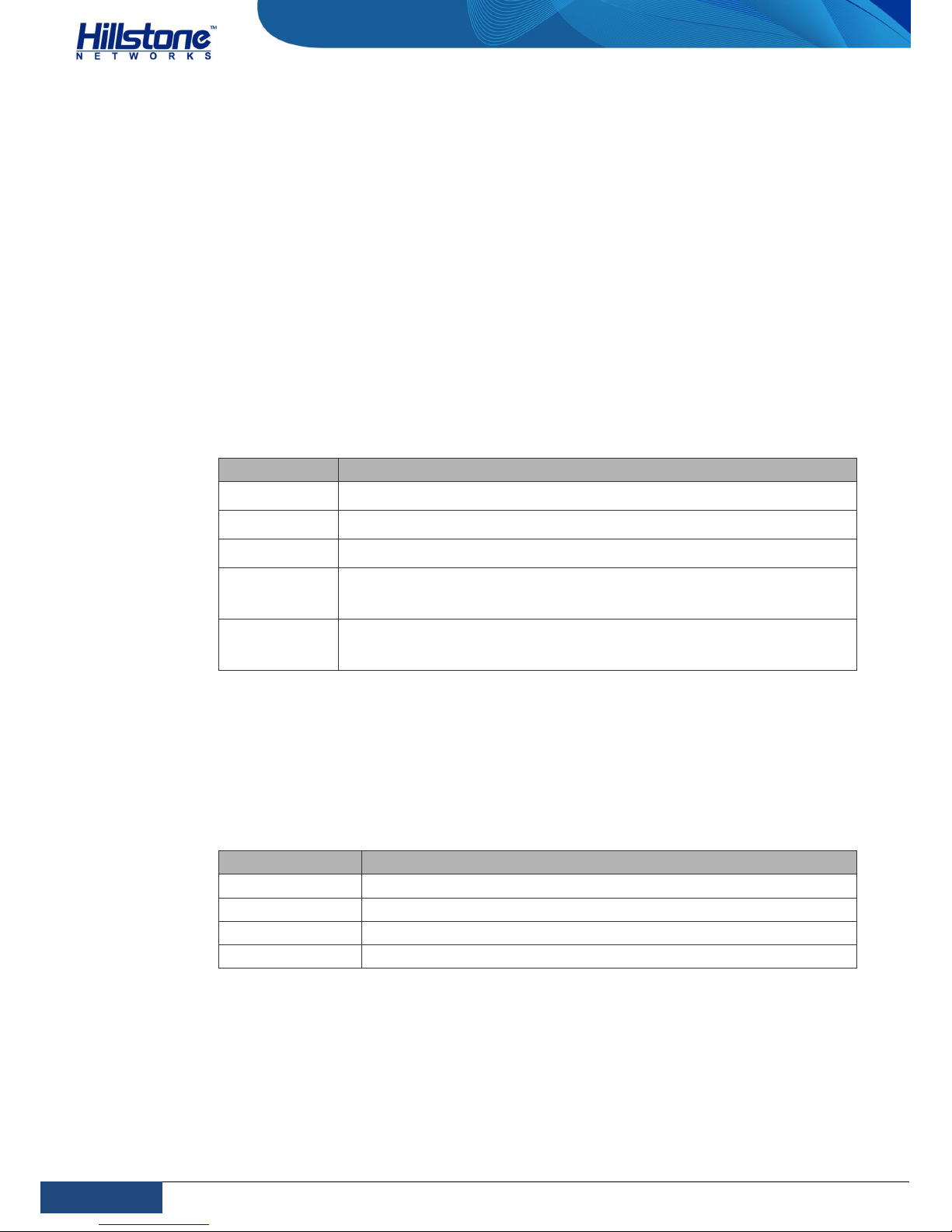
There is a hard disk module at the back panel of the device. The hard disk module
mainly stores logs and achieves the goals of storing data and system software
separately.
Ports
This section introduces attributes of ports on the Hillstone devices, including
console port, auxiliary port, USB port, gigabit copper port, SFP port and XFP port.
Console Port
Hillstone SG-6000 T-Series device provides an RS-232C asynchronous serial
console port for you to configure the appliance. Attributes for the console (CON)
port are shown in the table below:
Table 10: Console Port Attributes
Attribute Description
Connector RJ-45
Port Standard RS-232C
Baud Rate 9600/19200/38400/57600/115200 bit/s
Services
Connect the CON port to the serial port of a PC and run a terminal
emulation program on the PC to configure the appliance.
Transmission
Medium
Console cable
Auxiliary Port
Hillstone SG-6000 T-Series device provides an RS-232C asynchronous serial
auxiliary (AUX) port. Attributes for the auxiliary port are shown in the following
table:
Table 11: Auxiliary Port Attributes
Attribute Description
Connector RJ-45
Port Standard RS-232C
Baud Rate 115200 bit/s
Services Connect the external Bypass module of Silicom.
USB Port
Hillstone SG-6000 T-Series device provides an USB host port. Attributes for the USB
host port are shown in the table below:
Page 20
13
Chapter 1 Introduction
|
Hillstone
Hillstone SG-6000 T-Series Hardware Reference Guide
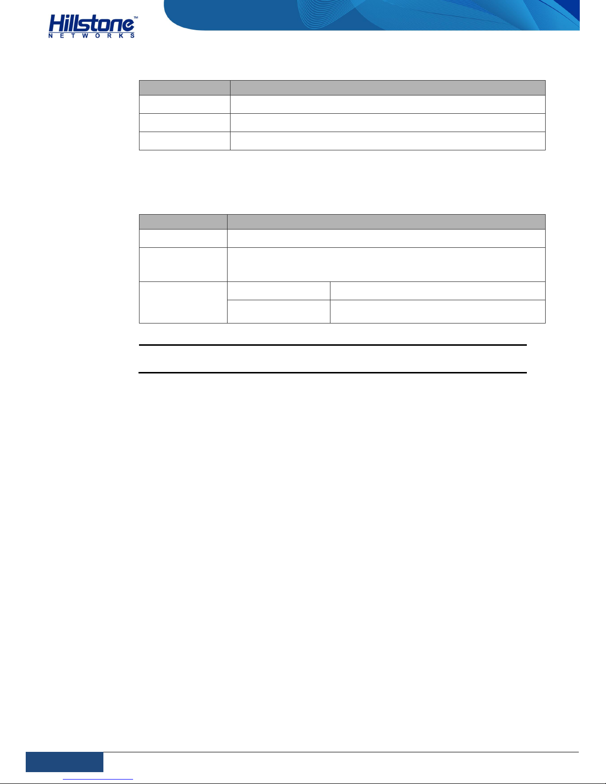
Table 12: USB Host Port Attributes
Attribute Description
Connector USB Type-A interface
Port Standard USB 2.0 host interface
Negotiation Mode 1.1/2.0 autosensing
SFP Port
Table 13: SFP Port Attributes
Attribute Description
Connector SFP
Frame Format
Ethernet_II
Ethernet_SNAP
Negotiation
Mode
SFP optical module 1000Mbps
SFP copper module
1000Mbps
Full-duplex
Caution: To avoid dust falling into the SFP socket, you should place a rubber
dust cap (originally in the accessory box) over the SFP port.
The SFP port of Hillstone SG-6000 T-Series device supports the SFP optical module.
When connecting the SFP port to an Ethernet cable, use the SFP transceiver.
Currently, the SFP port supports the FCLF-8520-3 SFP transceiver produced by
Finisar.
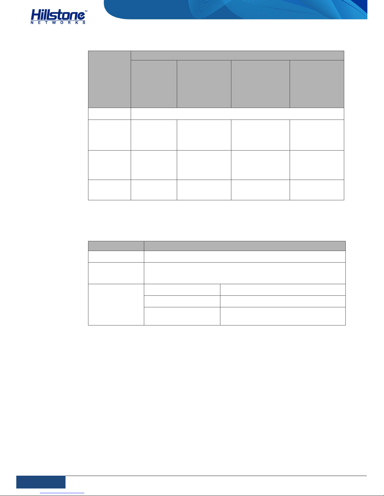
When using SFP optical modules in the SFP port, select the optical fiber with the LCType optical connector. Hillstone SG-6000 T-Series device supports five types of
1000Base-FX SFP optical modules. All optical modules are hot-swappable.
Page 21
14
Chapter 1 Introduction
|
Hillstone
Hillstone SG-6000 T-Series Hardware Reference Guide
Table 14: SFP Optical Module Attributes
Attribute
Description
Short-haul
Multimode
Optical
Module
(850nm)
Medium-haul
single-mode
Optical Module
(1310nm)
Long-haul
Single-mode
Optical Module
(1310nm)
Ultra-long
Haul
Single-mode
Optical Module
(1550nm)
Connector
LC
Fiber Type
50/125μm
multi-mode
fiber
9/125μm
single-mode
fiber
9/125μm
single-mode fiber
9/125μm
single-mode
fiber
Maximum
Transmission
Distance
0.3km 10km 40km 80km
Central
Wavelength
850nm 1310nm 1310nm 1550nm
SFP+ Port
Table 15: SFP+ Port Attributes
Attribute Description
Connector SFP+
Frame Format
Ethernet_II
Ethernet_SNAP
Negotiation
Mode
SFP+ optical module 10Gbps
SFP optical module 1000Mbps
SFP copper module
1000Mbps
Full-duplex
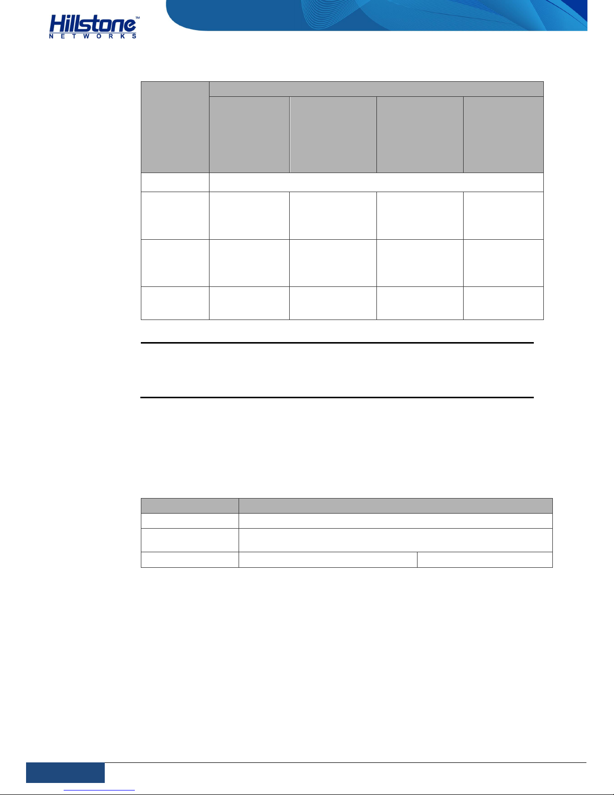
If you choose to use SFP+ optical module in SFP+ port, you should use LC-Type
optical connector. Hillstone device supports three types of SFP+ optical modules. All
optical modules are hot-swappable.
Page 22
15
Chapter 1 Introduction
|
Hillstone
Hillstone SG-6000 T-Series Hardware Reference Guide
Table 16: SFP+ Optical Module Attributes
Attribute
Description
Short-haul
Multimode
Optical
Module
(850nm)
Medium-haul
single-mode
Optical Module
(1310nm)
Long-haul
Single-mode
Optical Module
(1550nm)
Ultra-long
Haul Single-
mode Optical
Module
(1550nm)
Connector
LC
Fiber Type
50/125μm
multi-mode
fiber
9/125μm
single-mode
fiber
9/125μm
single-mode
fiber
9/125μm
single-mode
fiber
Maximum
Transmission
Distance
0.3km 10km 40km 80km
Central
Wavelength
850nm 1310nm 1550nm 1550nm
Caution:
To avoid dust falling into the SFP+ socket, you should place a rubber dust
cap (provided in the accessory box) over the SFP+ port.
The SFP+ port can be compatible with the SPF port.
XFP Port
Hillstone SG-6000 T-Series device and some interface expansion modules support
the XFP port. The following table describes the attributes of XFP port.
Table 17: XFP Optical Module Attributes
Attribute Description
Connector XFP
Frame Format
Ethernet_II
Ethernet_SNAP
Negotiation Mode XFP optical module 10Gbps
Hillstone SG-6000 T-Series device supports five types of 10GBase-FX XFP optical
module. The optical module provides the LC connector. All optical modules are hotswappable.
Page 23
16
Chapter 1 Introduction
|
Hillstone
Hillstone SG-6000 T-Series Hardware Reference Guide
Table 18: XFP Optical Module Attributes
Attribute
Description
Short-haul
Multimode
Optical
Module
(850nm)
Short-haul
Multimode
Optical
Module
(850nm)
Medium-
haul
Single-mode
Optical
Module
(1310nm)
Long-haul
Single-mode
Optical
Module
(1550nm)
Ultra-long
Haul Single-
mode Optical
Module
(1550nm)
Connector
LC
Fiber Type
50/125μm
multimode
fiber
62.5/125μm
multi-mode
fiber
9/125μm
single-mode
fiber
9/125μm
single-mode
fiber
9/125μm
single-mode
fiber
Maximum
Transmiss
ion
Distance
0.3km
(984.3ft)
0.033km
(108.3ft)
10km 40km 80km
Central
Wavelengt
h
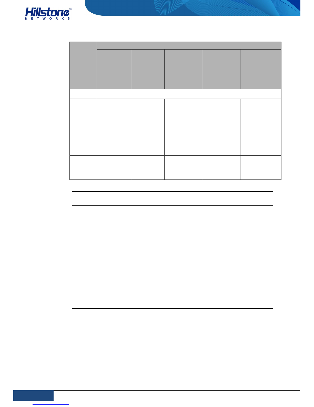
850nm 850nm 1310nm 1550nm 1550nm
Caution: To avoid dust falling into the XFP socket, you should place a rubber
dust cap (originally in the accessory box) over the XFP port.
Power Switch
There is a power switch at the front panel of Hillstone SG-6000 T-Series device.
After supplying the device with electricity, the device powers up automatically. To
power off the device, take the following steps:
1. Use the save command to save the current configurations.
2. Press the power switch for 4 seconds. The system starts to close each
software process.
3. After closing software processes, the device powers off.
4. When the PWR LED is red and always on and the HDD LED is off, you can
remove the power cord.
Caution: To reboot the device after it powers off, you must wait for at least 10
seconds and then press the power switch.
CLR Button
The CLR button is the pinhole of the front panel and is used to reset the device
back to the factory default settings. You can restore access to the device with this
button if the login password is lost.
Page 24

17
Chapter 1 Introduction
|
Hillstone
Hillstone SG-6000 T-Series Hardware Reference Guide
Warning: Use this button with caution. Resetting the appliance will clears all
existing configurations.
To reset the device back to the factory default settings, take the following steps:
1. When the device is working, press the CLR button in the pinhole. The device
will reboot.
2. After the device reboots, the CON port prints the message: CLR button
pressed and the STA and ALM LEDs turn to constantly red. The device will
reboot again after the LEDs turn off.
Expansion Slot
The chassis height of SG-6000-T5860 and SG-6000-T5060 is 2U with four half-U
expansion slots (Slot 1-4).The chassis height of SG-6000-T3860 is 2U with two
half-U expansion slots (Slot 1 and Slot 2).
Follow the rules below when inserting the expansion modules into expansion slots.
The XFP port expansion module can only be inserted into the Slot 3 and Slot
4.
The SFP port expansion module can be inserted into any slots.
Caution: Cover the expansion slot with a blank panel if the slot has no
expansion module installed. Otherwise, the uncovered slots will affect the
completeness of the heat dissipation system.
Cooling System
The cooling system includes 1 fan tray and 1 anti-dust mesh that keep the internal
temperature below a maximum acceptable level and ensure each component works
in the appropriate temperature environment.
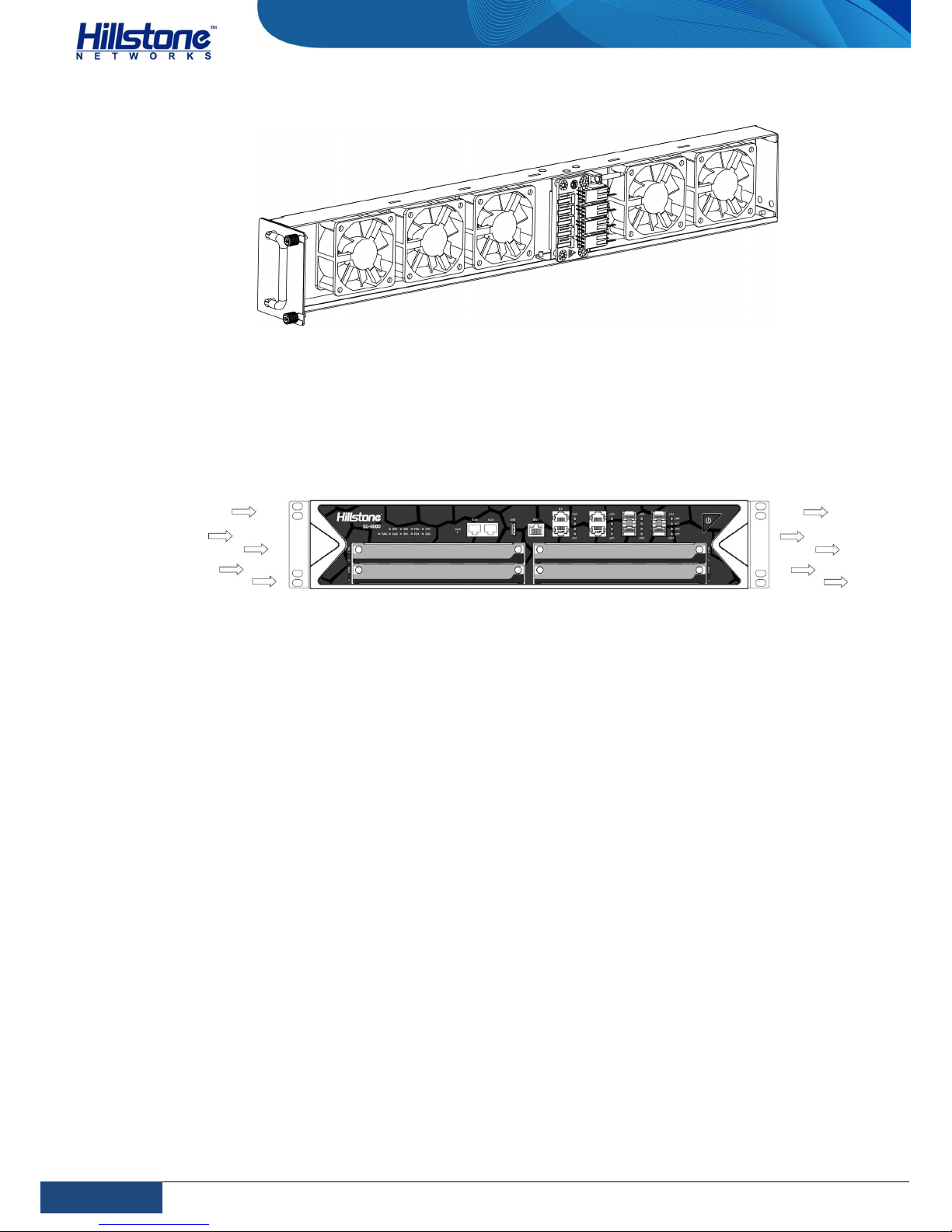
The fan tray is vertically installed on the left side of the back panel and it is made of
5 small fans. The anti-dust mesh is vertically installed on the right side of the back
panel and it is the air intake vent. Hillstone suggest purchasing an auxiliary antidust mesh for the situation that the original anti-dust mesh is sent to Hillstone for
clearing. Besides, it is recommended that you should replace the anti-dust mesh
every 3 or 6 months according to the clearness status of your equipment room. To
purchase a new anti-dust mesh, contact Hillstone.
Page 25
18
Chapter 1 Introduction
|
Hillstone
Hillstone SG-6000 T-Series Hardware Reference Guide
Figure 16: Fan Tray
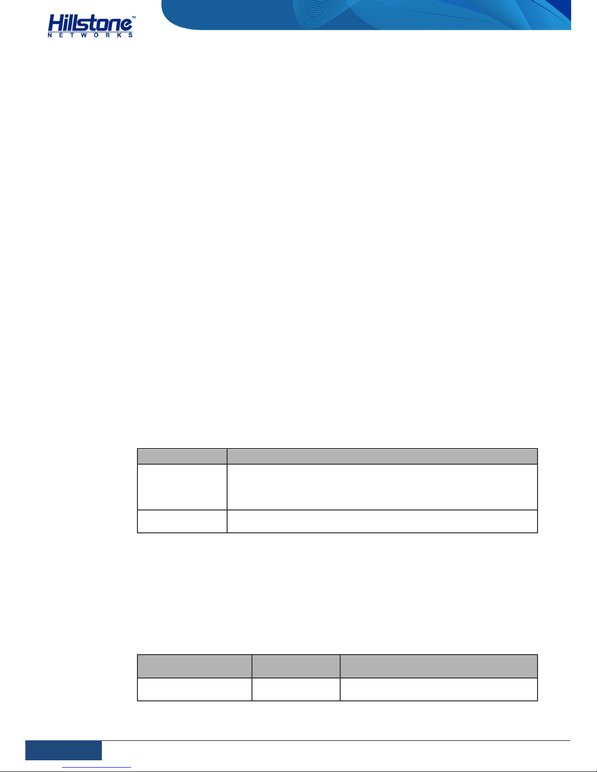
The air intake vent of the cooling system is located on the left side of the front
panel. After the air passes through the device, it discharges from the exhaust vent
on the right side of the back panel. To ensure the cooling system works normally,
remain adequate spaces around the device. The air circulation is shown as below:
Figure 17: Air Circulation
The ambient temperature of the working environment should keep between 0 and
40 degree Celsius. If a small fan works abnormally, the system will alert you using
the FAN LED. You must replace the fan tray with a new one. If two small fans work
abnormally, the system will power off without saving the current configurations.
Page 26
19
Chapter 2 Installation Preparations
|
Hillstone
Hillstone SG-6000 T-Series Hardware Reference Guide
Chapter 2 Installation Preparations
Introduction
This chapter introduces the preparations before installing the device, including the
installation site environment requirements, cabinet and rack requirements, and
unpacking. This chapter includes the following sections:
Installation site environment requirements
Cabinet requirements
Rack requirements
Package disassembly
Installation Site Environment Requirements
Hillstone SG-6000 T-Series device is designed for indoor use. To ensure the normal
operation and to prolong the service lifetime, the installation site must meet the
requirements below.
Temperature/Humidity Requirements
The installation site must keep the appropriate temperature and humidity in the
installation site. The requirements are shown as below:
Table 19: Temperature and Humidity Requirements
Category Requirement
Temperature
When the device is working, the requirement is between 0℃ and
40℃;
When the device is being stored, the requirement is between 20℃ and 70℃.
Relative
Humidity
10%-95% (non-condensing)
Clearness Requirements
It is required that there are no explosive, conductive, magnetic, and corrosive dusts
in the installation site. The dust concentration requirement in the equipment room
is shown as below:
Table 20: Dust Concentration Requirements in the Equipment Room
Mechanical Active
Material
Unit Content
Dust particle particle/m3
≤3×10⁴ (No visible dusts on the table in
3 days)
Page 27

20
Chapter 2 Installation Preparations
|
Hillstone
Hillstone SG-6000 T-Series Hardware Reference Guide
Note:Diameter of dust particle≥5μm
ESD Prevention
To prevent electrostatic discharge (ESD) damage, ensure that:
The device is well grounded. The grounding screw is properly grounded. Take
dustproof measures for the equipment room.
Take dustproof measures for the equipment room.
Maintain proper humidity and temperature levels.
Do not disassemble the equipment without permission from the vendor, or
you may cause danger and void your warranty.
EMI Prevention
All possible electromagnetic interference (EMI) sources, external or internal, can
affect the device by capacitance coupling, inductance coupling, electromagnetic
radiation, and common impedance coupling (including the grounding system).
To prevent or reduce EMI:
Take measures to protect the power system from power interference.
It’s better to separate the floor where the device is installed from the
grounding device and lighting-proof device of the power source.
Keep the device away from radio stations, radar, and other high-frequency
and high-current devices.
Use electromagnetic shielding when necessary.
Cabinet Requirements
Hillstone SG-6000 T-Series device is designed to fit in standard 19-inch cabinet.
The device can be installed in a 19-inch (or larger) cabinet.
Cabinet Size and Clearance
Install the device in at least 19-inch standard cabinet. Larger cabinet and adequate
space can ensure better ventilation and heat dissipation.
Ventilation Requirements
When the device is placed in the center of the cabinet, you must ensure the
ventilation and heat dissipation system are well. See the following suggestions:
The cabinet’s ventilation and heat dissipation system are well and it can
dissipate the heat produced by the device.
Ensure the dissipated air will not flow into the device again.
Page 28

21
Chapter 2 Installation Preparations
|
Hillstone
Hillstone SG-6000 T-Series Hardware Reference Guide
Ensure the path of the cables used by the device will not affect the heat
dissipation as far as possible.
Rack Requirements
Hillstone SG-6000 T-Series device can be installed in 19-inch four-post racks.
Rack Size and Strength
The rack rails must be spaced widely enough to accommodate the device chassis's
external dimensions: 440.0 mm high, 515.0 mm deep and 88.4 mm wide. Ensure
the rack is strong enough to hold the weight of the fully configured device.
Clearance Requirements
Ensure there is proper space around the rack for ventilation, heat dissipation, and
device maintenance.
For better heat dissipation, ensure the sufficient ventilation around the device.
Keep enough spaces between two devices and between the device and other
objects.
When installing or moving the hardware components of the device, ensure
there are enough spaces around the devices.
Connection to Building Structure
Always secure the rack to the structure of the building. If your geographical area is
subject to earthquakes, bolt the rack to the floor. For maximum stability, also
secure the rack to ceiling brackets.
Unpacking
Verify the parts received according to your purchasing contract and packing list to
ensure that you have received all the items necessary. The expansion modules and
power supply modules will be packaged independently. If you have any problem,
please contact Hillstone Support.
Page 29

22
Chapter 3 Installation
|
Hillstone
Hillstone SG-6000 T-Series Hardware Reference Guide
Chapter 3 Installation
Installation Processes
Before installation, prepare the site according to the requirements in Chapter 2
Installation Preparations, and use the procedures below to install the device.
1. Perform security check according to Safety Requirements.
2. Install the device in a rack or cabinet according to Installing the Device on a
Rack or Cabinet.
3. Install the expansion modules and power modules you need according to
Installing Interface Expansion Modules and Installing a Power Supply Module.
4. Ground the device. See Connecting the Grounding Wire.
5. Connect Console cable for the device. See Connecting the Console Cable.
6. Connect the power supply cable according to Connecting the AC Power Cable
or Connecting the DC Power Cable.
7. Verify the installation according to Verification after Installation.
Safety Requirements
To avoid personnel injury or harm to the device, follow the guidelines in this
section. Note that this manual does not cover all the safety requirements, warnings
or guideline for operating electric devices.
General Safety Warnings
The following guidelines apply to any operational situations:
Make sure only authorized personnel can perform operations to the device.
Keep the area around the device free from dust, fire and humidity.
Keep tools and accessories away from places where people might get tripped
while walking.
Do not wear loose clothes or jewelry, such as earrings and bracelets, as they
might be caught in the chassis.
Do not attempt to lift an object that is too heavy for one person to handle.
Never manipulate the wire in electrical storms.
Do not open or remove the chassis cover or metal parts unless it is specifically
instructed in the manual.
Avoid spilling liquid onto the device or onto any part.
Page 30

23
Chapter 3 Installation
|
Hillstone
Hillstone SG-6000 T-Series Hardware Reference Guide
Preventing ESD Damage
The hardware components are sensitive to electric damages. Static voltages can be
easily generated whenever you handle plastic or foam packing material or if you
move components across plastic or carpets. Some components can be impaired by
static voltages.
To minimize the potential of electrostatic discharges (ESD), follow the rules:
Always wear the antistatic gloves and ensure the antistatic gloves touch your
skin directly.
When installing and uninstalling the hardware components, always keep the
side with elements being upward and package the components in an antistatic bag or anti-static surface. When returning the hardware components to
Hillstone, package the components in anti-static bags first.
Fire Safety Requirement
The installation site should conform to common fire safety regulations and have fire
extinguishers in the room. The equipment room forbids smoking and open fires. In
the event of fire, the safety of personnel is the primary concern. Cut off all the
power supplies and then use fire extinguishers.
Installing the Device on a Rack or Cabinet
This section describes how to install a device in a cabinet or rack. Before you begin
to install the device, verify the following:
The installation site is prepared according to Installation Site Environment
Requirements.
You have read the specifications in the Safety Requirements.
Make sure the rack or cabinet is secured to the floor and the site ventilation is
adequate for heat dissipation and maintenance.
Installing Devices
Take the following steps to install the devices in a cabinet or a rack:
1. Wear antistatic gloves. For more information, see ESD Prevention.
2. Make sure the device is not powered and it will not be powered during the
removing process.
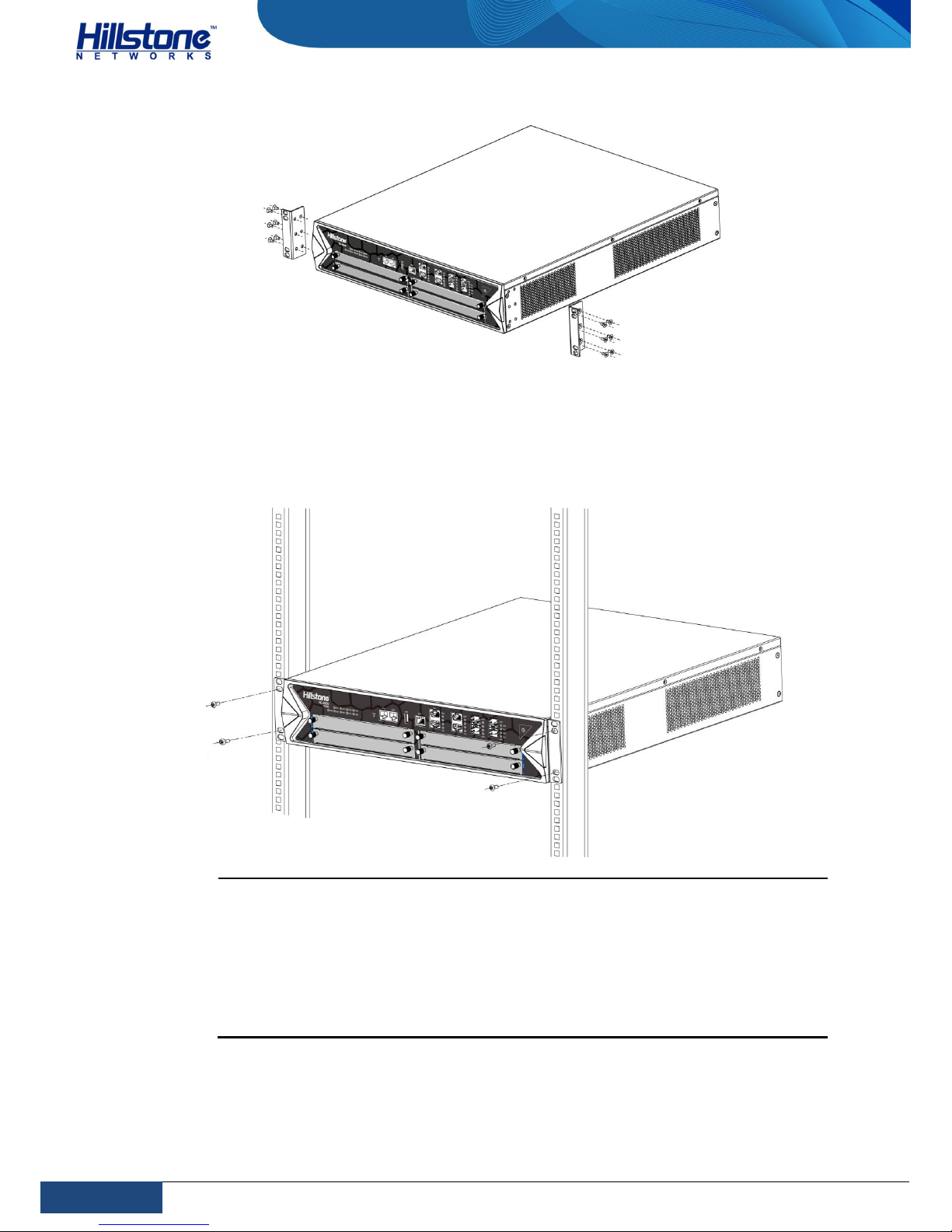
3. Use rack-mounting ear to mark the positions of floating nuts on the front
rack posts.
4.
Attach rack-mounting ears to the left and right side panels of the chassis
respectively.
Page 31
24
Chapter 3 Installation
|
Hillstone
Hillstone SG-6000 T-Series Hardware Reference Guide
Figure 18: Installing Rack-mounting Ears
5. Use the screws to attach the left and right brackets to the rack.
6.
Verify the alignment of the screws. Make sure every two screw pairs are in
the same horizontal line.
Figure 19: Installing the Device in a Rack
Cautions:
The rack-mounting ears cannot bear weight. Make sure the chassis is
supported by the platform under it when mounted into a rack.
If the rack accommodates only one device, put the device on the
bottom.
The floating nuts in the accessory box can only fit in the 9mm x 9 mm
squared holes of standard racks and they can be used when no original
rack nuts available.
Installing Interface Expansion Modules
This section describes how to install the installation expansion modules.
Page 32
25
Chapter 3 Installation
|
Hillstone
Hillstone SG-6000 T-Series Hardware Reference Guide
Take the following steps to install the interface expansion modules
1. Make sure the device is not powered and you have worn antistatic gloves.
2. Face the front panel of the device.
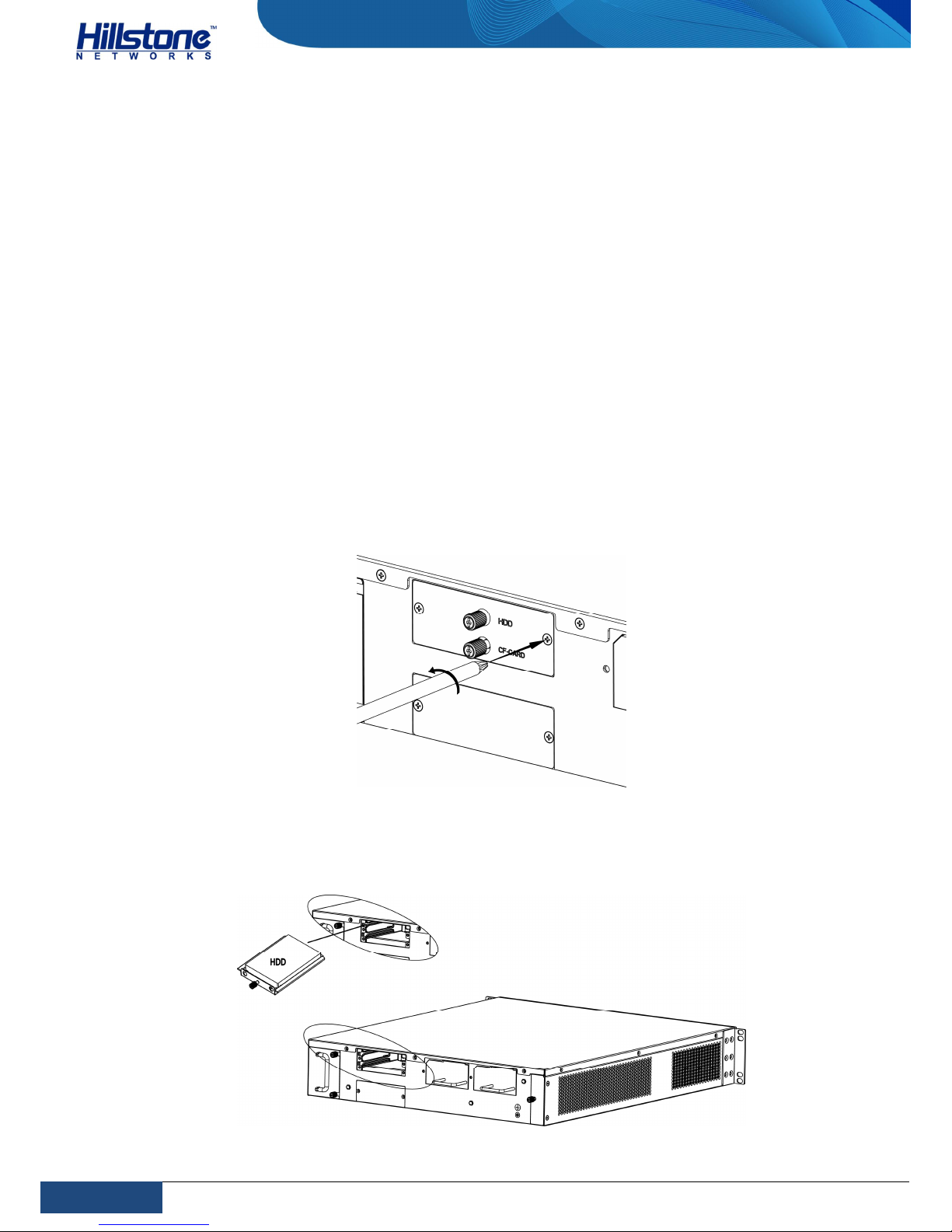
3. Use a screwdriver to remove the blank panel from the expansion slot you
want to insert.
4. Slide the expansion module into the slot until you feel resistant.
5. Tighten the screws on the expansion module.
Installing a Hard Disk Module
This section describes how to install the hard disk module.
1. Make sure the device is not powered and you have worn antistatic gloves.
2. Face the back panel of the device.
3. Use a screwdriver to remove the blank panel from the hard disk slot you
want to insert.
Figure 20: Removing the Blank Panel
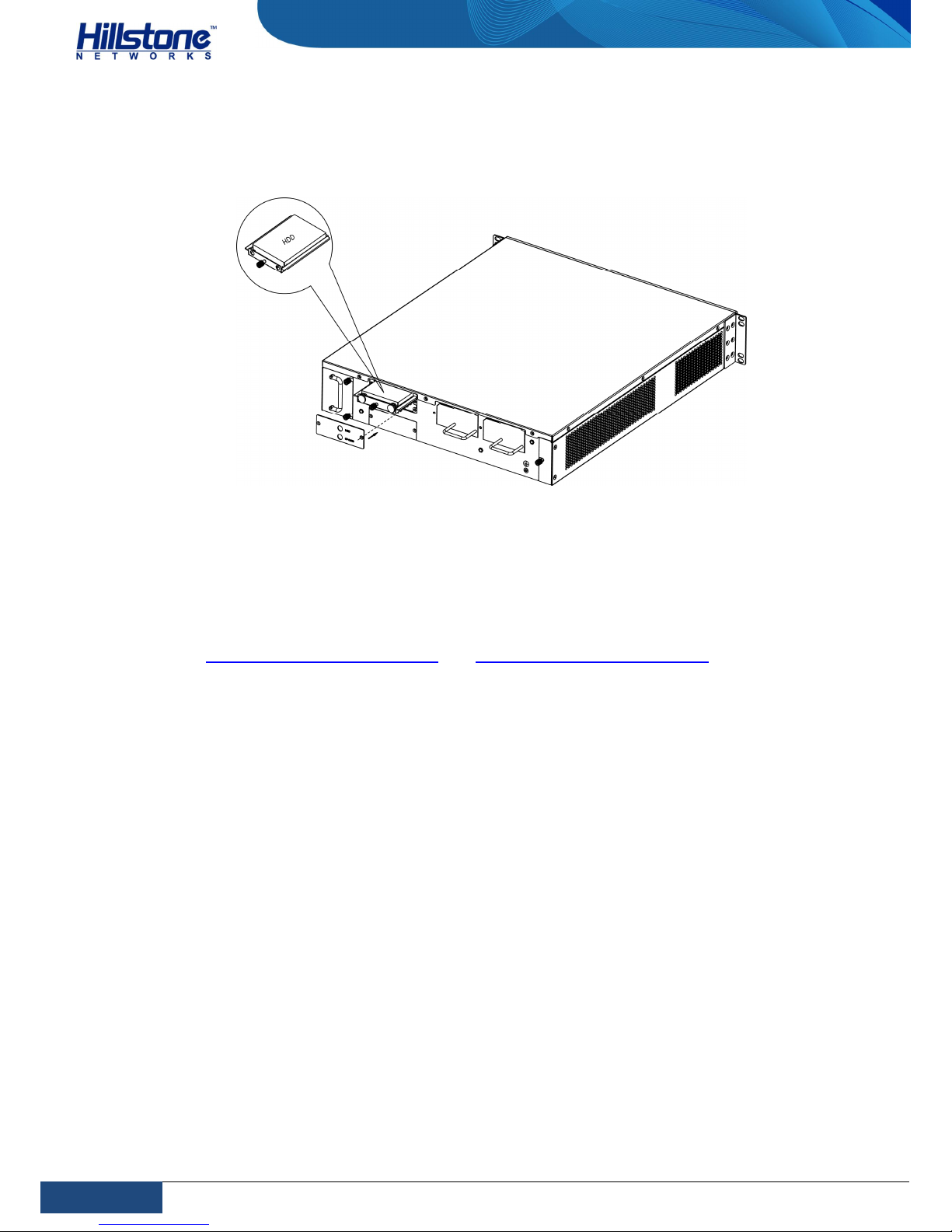
4. Slide the hard disk module into the slot until you feel resistant.
Figure 21: Installing the Hard Disk Module
Page 33
26
Chapter 3 Installation
|
Hillstone
Hillstone SG-6000 T-Series Hardware Reference Guide
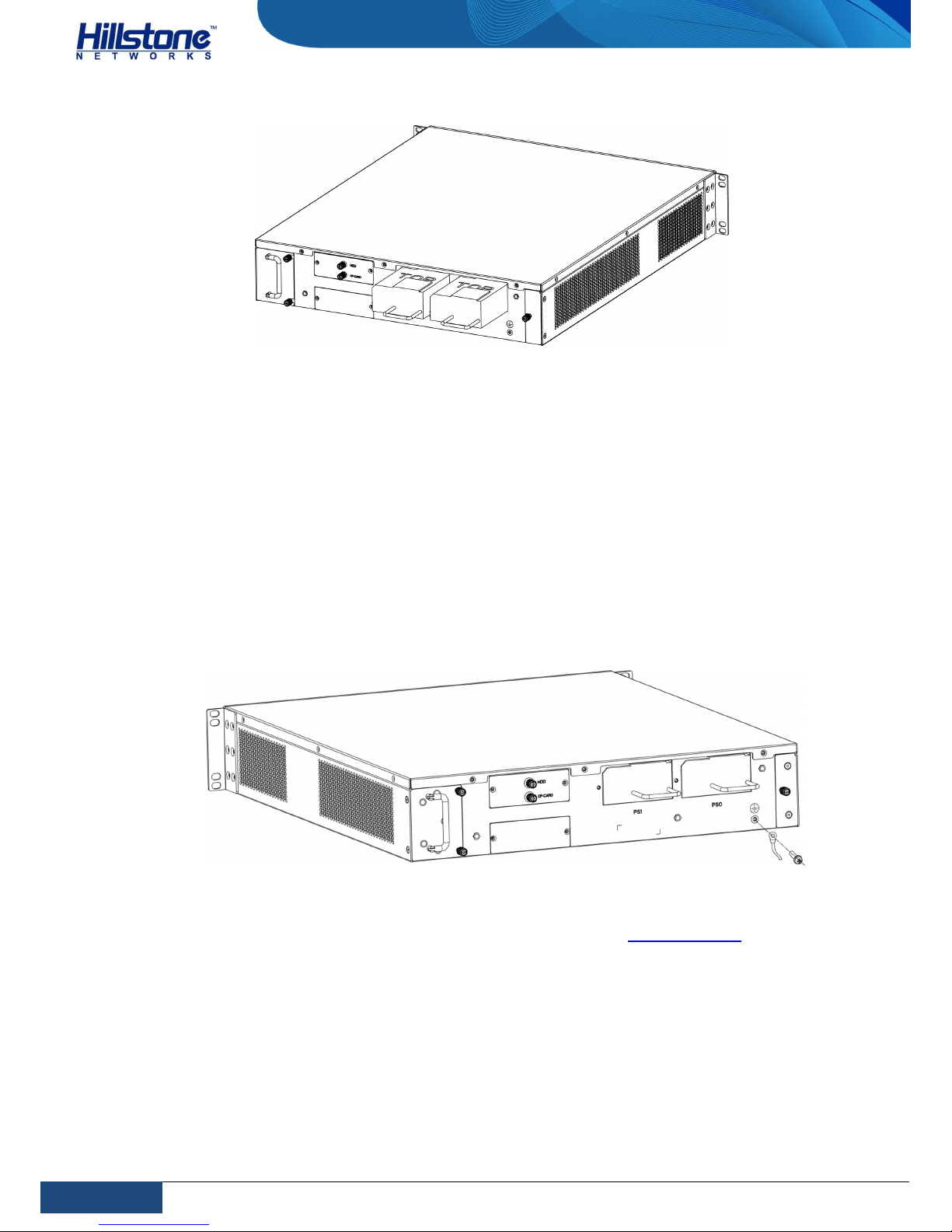
5.
Use a screwdriver to re-install the blank panel into the hard disk slot.
Figure 22: Installing the Blank Panel
Installing a Power Supply Module
This part describes how to install and remove the power supply module. The
methods of installing AC power supply module and DC power supply module are the
same, but the cable installation methods are different. For more information, view
Connecting the AC Power Cable and Connecting the DC Power Cable. Take the
following steps to install the power supply module in the device:
1. Make sure the power supply module is not connected to any power source
and there is no chance it will be powered during the process.
2. Face the back panel of the chassis.
3. A blank panel is installed in the PS1 power slot. Use a screwdriver to remove
the blank panel from the PS1 slot. No blank panel is installed in the PS0
power slot and you can skip this step if you want to install the power supply
module in the PS0 power slot.
4.
Slide the power module straight into the slot until it is fully seated in the
chassis slot. You can hear a click of the lock stuck in the chassis. Verify that
the panel of the power module is level with the chassis panel.
Page 34
27
Chapter 3 Installation
|
Hillstone
Hillstone SG-6000 T-Series Hardware Reference Guide
Figure 23: Installing the Power Supply Module
Connecting Cables
This part describes how to connect the grounding wire, power cable, Ethernet cable,
optical cable and power cable.
Connecting the Grounding Wire
To avoid electrostatic discharge, you must correctly connect the chassis to the earth
ground by a grounding wire. The grounding screws are in the back panel of the
chassis, as shown in the figure below. Note that Hillstone does not provide
grounding wire.
Figure 24: Grounding Screw
1.
Wear antistatic gloves. For more information, see ESD Prevention.
2. Ensure all cable ends are clean and bright.
3. Connect the grounding cable to a proper earth ground.
4. Connect the other end of the grounding cable to the grounding screw on the
chassis and tighten it with a Phillips screwdriver.
5. Arrange the grounding cable so that it does not block the hardware
components and it does not drape where people might trip over.
Page 35

28
Chapter 3 Installation
|
Hillstone
Hillstone SG-6000 T-Series Hardware Reference Guide
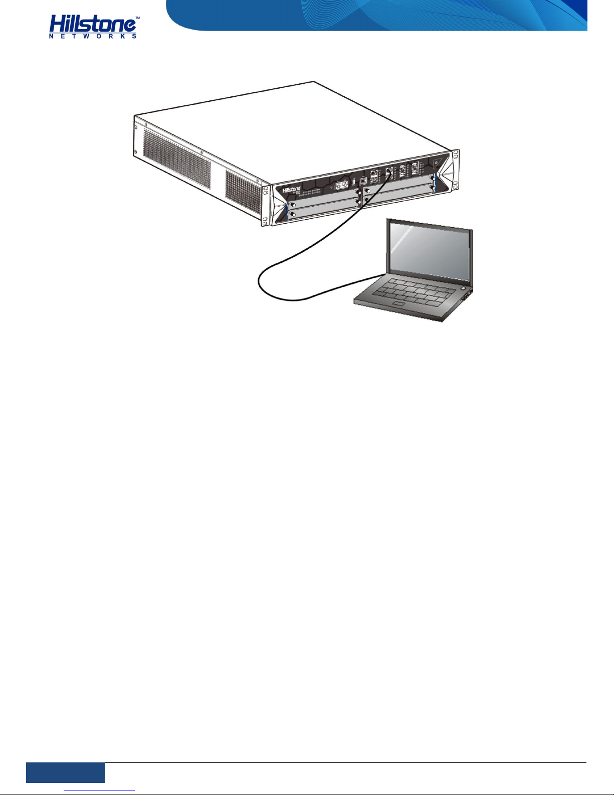
Connecting the Console Cable
The device provides an RS-232C asynchronous serial console (CON) port, through
which you can configure the appliance. The console cable is an 8-core shielded
cable, which has an RJ-45 connector that can be connected to the Console port of
the appliance and a DB-9 (female) connector that can be connected to the serial
port of a console terminal.
To connect the Console cable, take the following steps:
1. Select a console terminal. You may choose an ordinary PC or a standard
ASCII terminal with an RS-232C serial port.
2. Connect the console cable. Connect the RJ-45 end of the cable to the
Console port of the appliance, and then connect the DB-9 connector of the
cable to the console terminal.
The Auxiliary (AUX) port is used to configure the slave SCM. Connecting the AUX
port is similar to connecting the Console port.
Connecting the Ethernet/Optical Cable
The interface expansion module supports SFP ports, SFP+ ports, and XFP ports. SFP
port and SFP+ port can accommodate optical module or copper transceiver; when
you use optical SFP or SPF+ module, you can use single-mode or multi-mode
optical cable to connect. The XFP port is also compatible with single-mode or multimode cable.
All SFP, SFP+, and XFP optical modules use LC-type optical connector; therefore,
you should connect the optical modules using optical fiber ended with LC-type
connector. All optical transceivers are hot-swappable.
Connecting the Ethernet Copper Cable
Follow the guidelines below when connecting cables to the ports:
Be careful not to connect the Ethernet port to the wrong ports. Read the label
above the port carefully.
For electrical Ethernet connection, use crossover cable or straight-through
cable.
Page 36
29
Chapter 3 Installation
|
Hillstone
Hillstone SG-6000 T-Series Hardware Reference Guide
Figure 25: Connecting the Ethernet Copper Cable
Connecting the Ethernet Fiber Cable
Follow the guidelines below when connecting cables to the ports:
Be careful not to connect the Ethernet port to the wrong ports. Read the label
above the port carefully.
For SFP port connection, the optical module should be inserted into SFP port
before installing the LC-type connector to the optical module; the copper SFP
module should be connected by crossover cable or straight-through cable.
For SFP+ port connection, the optical module should be inserted into SFP+
port before installing the LC-type connector to the optical module; the copper
SFP+ module should be connected by crossover cable or straight-through
cable.
For XFP ports, insert the XFP optical module into the XFP port before
connecting the LC-type connector to the module.
Keep the followings in mind when connecting fiber cables:
The curvature radius should be greater than 10cm. Avoid excessive bending
of the cable.
Ensure the Tx and Rx ends are connected correctly.
Keep the connector of the optical cable clean.
Page 37
30
Chapter 3 Installation
|
Hillstone
Hillstone SG-6000 T-Series Hardware Reference Guide
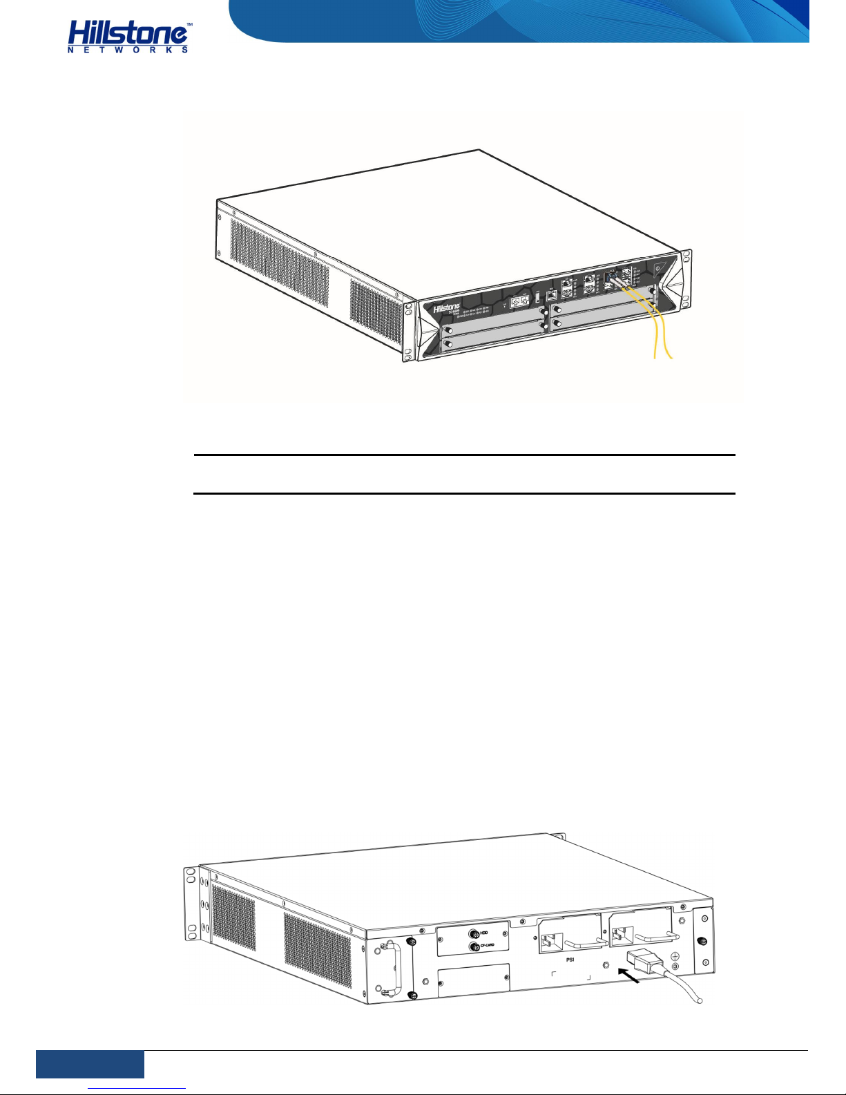
Figure 26: Connecting the Ethernet Copper Cable
Warning: Laser danger! To protect your eyes from radiation harm, do not stare
into a cable connector connected to a laser.
Connecting the AC Power Cable
The AC power cable is shipped with the chassis. Prepare a single-phase threeterminal power socket with a ground contact in advance. Normally, the ground
contact of the power supply system in a building was buried during construction
and cabling. Before connecting the AC input power cable, you must make sure that
the power socket is well grounded.
To connect the AC power cable, take the following steps:
1. Make sure the ground wire is reliably connected to the earth ground.
2. Connect the AC power socket of the power source using the AC power cable.
To connect more cables, repeat this step.
3. Check PWR LED on the front panel. A shining LED indicates correct
connection.
Figure 27: Connecting an AC Power Cable
Page 38

31
Chapter 3 Installation
|
Hillstone
Hillstone SG-6000 T-Series Hardware Reference Guide
Connecting the DC Power Cable
To power the appliance with DC power source, use DC power cables to connect the
appliance and the external DC power source. Hillstone does not provide DC power
cables.
Warning: Before performing the procedure, ensure that the cable is not
connected with any power source and make sure the cables will not be powered
on during the process.
1. Ensure that the power source voltage is in accordance with required voltage
specified in Hardware Parameters.
2. Switch off the power source.
3. Ensure that the DC power module has been properly installed according to
the Installing a Power Supply Module.
4. If the terminal on the power supply module has a plastic cover, remove the
cover and keep it.
5. If the terminal on the power supply module has a plastic cover, remove the
cover and keep it.
6. Use a DC cable to connect the “+” (or “RTN”) terminal of the appliance to
the “+” terminal of the power source; use another DC cable to connect the
“-” (or “-48V”) terminal to the “-” terminal of the power source.
7. Verify the connection is correct and fasten the cables using a screwdriver.
8. Recover the plastic cover(s) to the original terminal(s).
9. To connect more DC power cables, repeat Step 3 to 7.
Verification after Installation
After you complete the installation with all the above steps, you still need to verify
the following items.
All the cables are properly connected.
The grounding wire of the device is correctly connected.
The air vents on both side panel of the device are unblocked, and there is
enough space around for heat dissipation.
The expansion modules, power supply modules and fan tray are correctly
installed (for some products).
The power source meets the requirements of the device.
Page 39
32
Chapter 4 Boot and Configuration
|
Hillstone
Hillstone SG-6000 T-Series Hardware Reference Guide
Chapter 4 Boot and Configuration
Introduction
This chapter describes how to perform initial system boot and basic configuration of
Hillstone SG-6000 T-Series device. The configuration uses PC as the console
terminal.
Establishing a Configuration Environment
Hillstone SG-6000 T-Series device supports both local and remote configuration.
Administrators can use the following configuration methods:
Console (CON) connection
WebUI
Telnet or SSH
Console (CON) Connection
For initial system configuration, you have to establish a Console connection
environment (connect the device to a configuration terminal through its Console
port).
To connect the PC to the CON port of the device, take following steps:
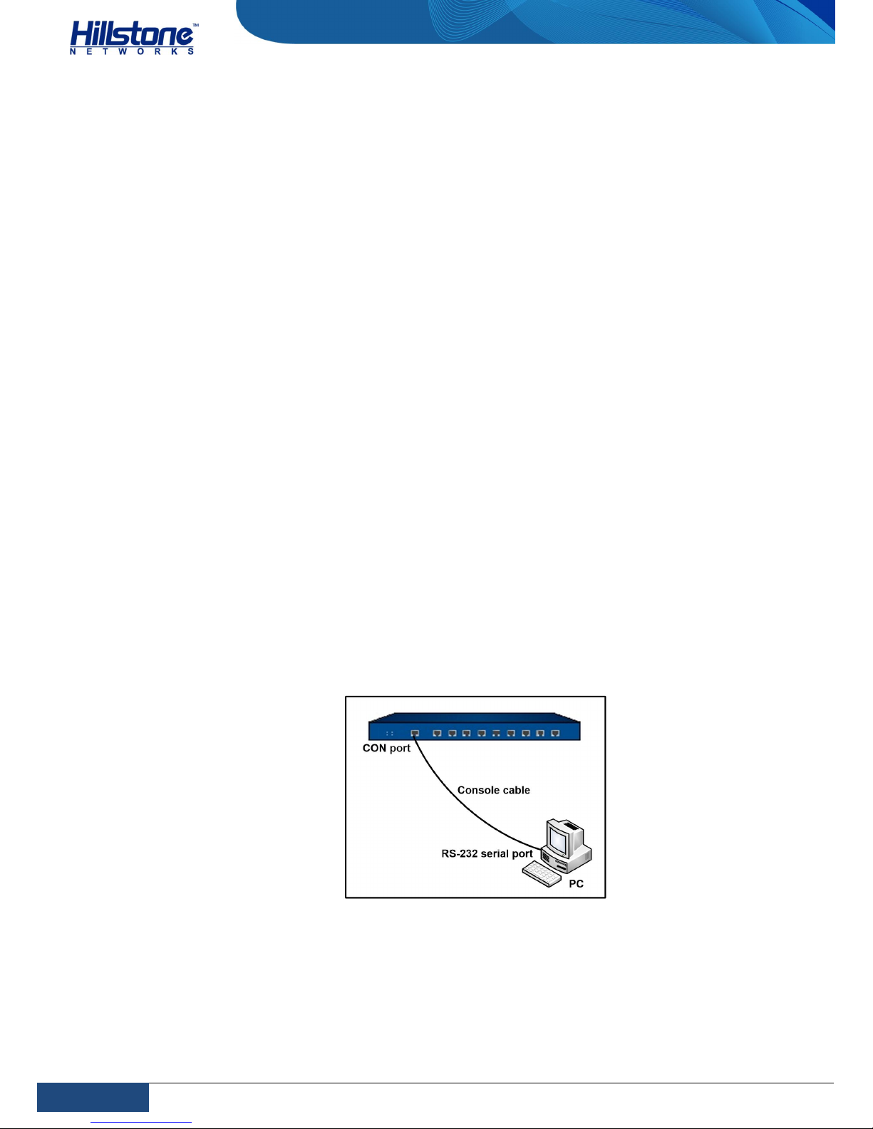
1. Set up a local configuration environment. Connect the Console port to the
serial port of a PC through a console cable, as shown in the figure below:
Figure 28: Console Port Configuration
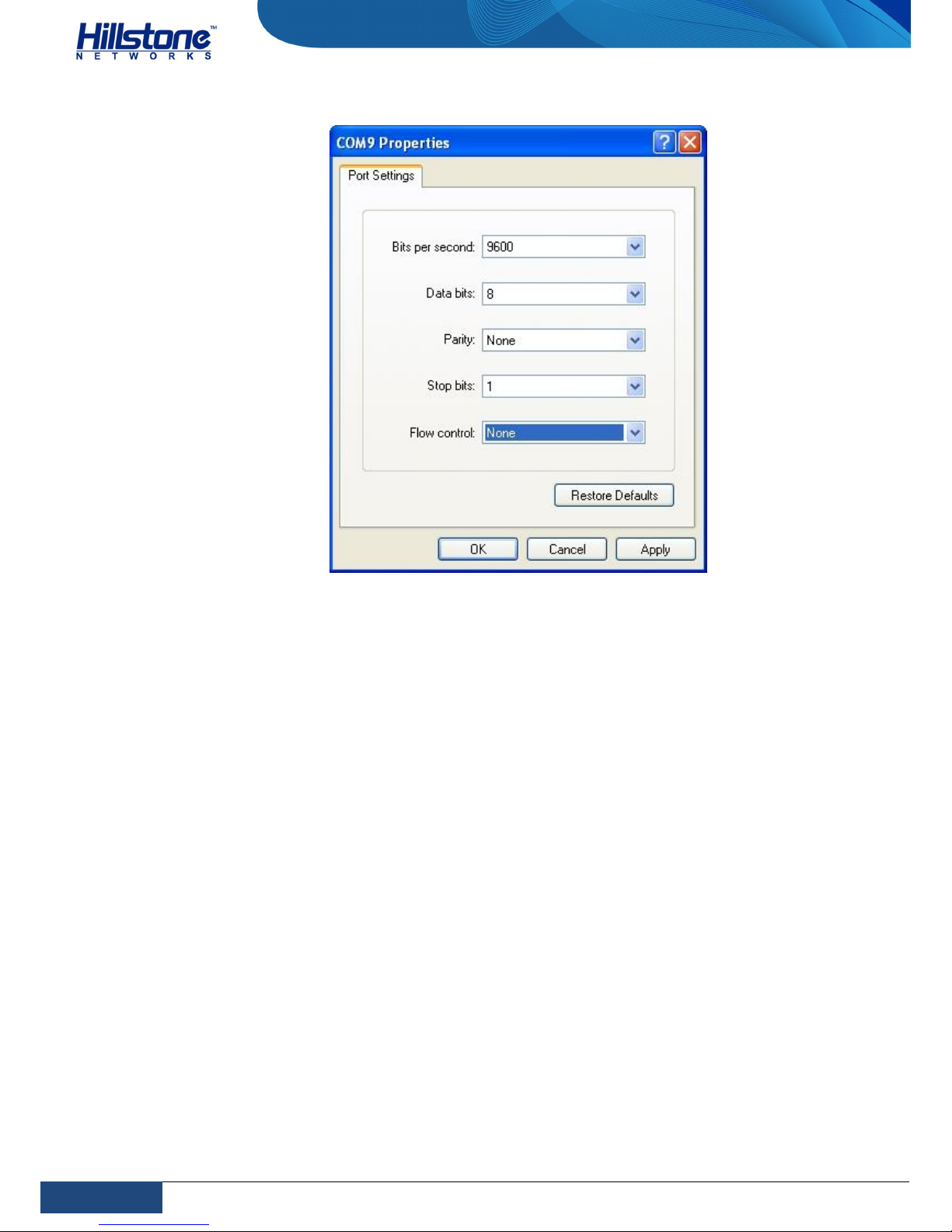
2. Run the terminal emulation program on the PC (e.g. hyper terminal of
Windows XP/Windows 2000) to set up a connection. Set the parameters of the
terminal session to 9600bps, 8 data bits, 1 stop bit, none parity, and none
flow control, as shown in the figure below:
Page 40
33
Chapter 4 Boot and Configuration
|
Hillstone
Hillstone SG-6000 T-Series Hardware Reference Guide
Figure 29: Setting Parameters for the Terminal Session
3. Switch on the power supply, and the appliance performs self-test and
initializes the configuration automatically. If the booting succeeds, the system
will display the command line prompt “login”. Enter the default administrator
name and password “hillstone” at the “login” and “password” prompts, press
“Enter”. And now you are successfully logged in and accessing the CLI.
4. Enter commands to configure or view running status. Enter a question mark
“?” to get help on commands whenever you want.
WebUI
The ethernet0/0 (e0/0) port has a default IP address of 192.168.1.1/24, and all the
management functions of this port are enabled by default. Administrators can
access the WebUI through e0/0.
To log in the appliance’s WebUI, take the following steps:
1. Set up the IP address of the management PC on the same subnet as
192.168.1.1/24. Connect the management PC to the e0/0 port through an
Ethernet cable.
2. Launch a Web browser of the management PC, enter the URL
http://192.168.1.1 in the address bar, and then press Enter.
3. Enter the default administrator name and password “hillstone” in both the
Login and Password text boxes.
Page 41

34
Chapter 4 Boot and Configuration
|
Hillstone
Hillstone SG-6000 T-Series Hardware Reference Guide
4. Click the Login button to enter WebUI main page. Then you can set other
configurations to the appliance.
Telnet and SSH
You can also establish Telnet and SSH configuration environments.
Basic Configuration
Before beginning to use the device, you should be familiar with its features and
your network deployment. Different device position in the network requires
different topology design, working mode and policy configuration.
The basic configurations may include:
1. Create security zones, including the link layer (L2) and network layer (L3).
Bind different interfaces to correct security zones respectively.
2. Assign IP addresses to interfaces.
3. Configure the management functions of the interfaces and create the security
policy rules.
4. Assign proper network addresses and configure the NAT rules as needed.
5. Configure routing of the system to ensure the network connectivity.
6. Configure security policy rules between security zones.
7. Configure network parameters, such as DHCP and DNS agent, etc.
Page 42

35
Chapter 5 Hardware Maintenance and Replacement
|
Hillstone
Hillstone SG-6000 T-Series Hardware Reference Guide
Chapter 5 Hardware Maintenance and Replacement
Introduction
This chapter provides information on how to maintain and replace power module,
expansion module and fan tray.
General Maintenance
For optimum performance, use the following routine maintenance procedures:
Inspect the installation site for moisture, temperature and cleanness
according to Installation Site Environment Requirements.
Check the cables and make sure they are not loosened.
Inspect the air inlet and outlet. Make sure that there is no object blocking
the air inlet and the air outlet has not gathered any heavy dust. If the dust
is so thick that it blocks the air flow, clean the cooling system or replace a
fan tray. See Replacing a Cooling System.
When you maintain the hardware components, note that:
Always wear antistatic gloves. See ESD Prevention.
When you inspect or move the modules, hold the module with both hands
without touching the electric components on the module.
The removed module should be placed into an antistatic bag or on an
antistatic table with component-side up.
Replacing a AC Power Supply Module
The device supports 1+1 power module redundancy. If you remove one power
module out of the chassis which has two power modules, the system can still work.
This chapter introduces how to replace the power supply module.
To replace an AC power module, take the following steps:
1. Unplug the AC power cable from the power supply source.
2. Wear antistatic gloves. See ESD Prevention.
3. Remove the power cable from the power module.
4. Pull the power module straight out of the chassis by pressing the lever and
hold the handle.
5. Put the removed power module into an antistatic bag or on a flat antistatic
table.
Page 43

36
Chapter 5 Hardware Maintenance and Replacement
|
Hillstone
Hillstone SG-6000 T-Series Hardware Reference Guide
6. Install a replacement power module (see Installing a Power Supply Module
and Connecting the AC Power Cable).
Note: If you do not want to install a new module, apply a blank plate over the
slot to avoid dust falling into the chassis.
Replacing a DC Power Supply Module
To replace a DC power module, take the following steps:
1. Switch off the power source and remove the DC power cable from the power
source.
2. Wear antistatic gloves. See ESD Prevention.
3. Loose the screws of the DC power cable using a Phillips screwdriver and
remove the cable.
4. Pull the power module straight out of the chassis by pressing the lever and
hold the handle.
5. Put the removed power module into an antistatic bag or on a flat antistatic
table.
6.
Install replacement power module (see Installing a Power Supply Module
and Connecting the DC Power Cable).
Note: If you do not want to install a new module, apply a blank plate over the slot
to avoid dust falling into the chassis.
Replacing Interface Expansion Modules
To replace interface expansion modules, take the following steps:
1. Wear antistatic gloves. For more information, see ESD Prevention.
2. Select the interface expansion module to be removed and remove all cables
in the module.
3.
Use a Phillips screwdriver to loosen the screws.
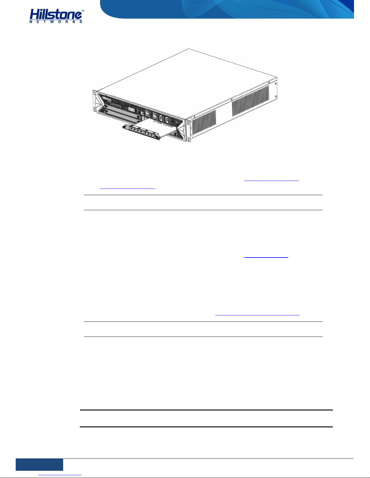
4. Hold the screws and pull the expansion module straight out of the chassis,
as shown in the figure below.
Page 44
37
Chapter 5 Hardware Maintenance and Replacement
|
Hillstone
Hillstone SG-6000 T-Series Hardware Reference Guide
Figure 30: Replacing an Expansion Module
5. Put the removed module into an antistatic bag with component-side up.
6.
To install a new interface expansion module, view Installing Interface
Expansion Modules.
Note: If you do not want to install a new module, apply a blank plate over the slot
to avoid dust falling into the chassis.
Replacing a Hard Disk Module
To replace the hard disk module, take the following steps:
1. Wear antistatic gloves. For more information, see ESD Prevention.
2. Remove the blank panel in the hard disk slot by using the Phillips
screwdriver.
3. Hold the screws and pull the expansion module straight out of the chassis.
4. Put the removed module into an antistatic bag or on a flat antistatic table.
5. To install a new hard disk module, view Installing a Hard Disk Module.
Note: If you do not want to install a new module, apply a blank plate over the slot
to avoid dust falling into the chassis.
Replacing a Cooling System
The cooling system of the device consists of 1 anti-dust mesh and 1 fan tray and
the fan tray has 5 fans. When the ventilation is inadequate due to fan tray failure or
anti-dust mesh block, you need to change the fan tray or clear the anti-dust mesh.
Both the fan tray and the anti-dust mesh are hot-swappable.
Note: You should clear the anti-dust mesh at least once a year even they can work
normally.
Page 45
38
Chapter 5 Hardware Maintenance and Replacement
|
Hillstone
Hillstone SG-6000 T-Series Hardware Reference Guide
Replacing a Fan Tray
When one fan is failed, you need to change the fan tray for device heat dissipation.
Hillstone suggest purchasing an auxiliary fan tray. When you change the original
fan tray, use the auxiliary one for heat dissipation. The fan tray is hot-swappable.
To prevent overheating, install the auxiliary fan tray immediately after removing
the original one.
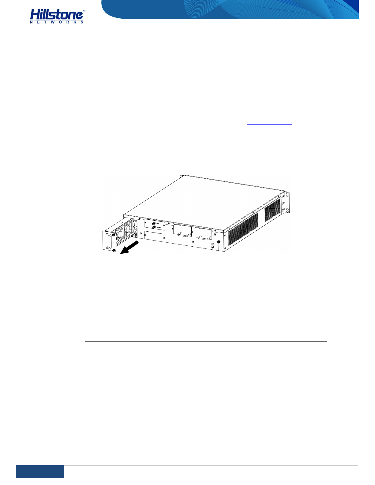
To replace the fan tray, take the following steps:
1. Wear antistatic gloves. For more information, see ESD Prevention.
2. Use a Phillips screwdriver to loosen the screws on the fan tray.
3.
Hold the handle of the fan tray and pull it out a little to disconnect it to
power. Wait till the fans stop spinning.
Figure 31: Removing the Fan Tray
4. After the fans have stopped spinning, pull the fan tray out of chassis.
5. Grasp the replacement fan tray with the screws on the right side of your
palm. Slide the fan tray into the slot until you feel resistant.
6. Tighten the screws on the fan tray.
Note: To prevent over-heating, you should install the replacement fan tray within
30 seconds after the existing fan tray is removed. If the system detects overheating, it will automatically switch off the power supply.
Replacing an Anti-dust Mesh
The anti-dust mesh is located at the right side of the back panel and it is the intake
vent of the cooling system. Dust on the anti-dust mesh blocks the ventilation and
leads to the overheating, which will cause the device failure.
Hillstone suggest purchasing an auxiliary anti-dust mesh. When you change the
original one, you can use the auxiliary one.
Take the following steps to remove the anti-dust mesh:
1. Loosen the screws.
Page 46

39
Chapter 5 Hardware Maintenance and Replacement
|
Hillstone
Hillstone SG-6000 T-Series Hardware Reference Guide
2. Hold the screws and pull the anti-dust mesh straight out of the chassis.
Take the following steps to install the anti-dust mesh:
1.
Hold the screws and slide the anti-dust mesh into the slot until you feel
resistant.
2. Tighten the screws on the anti-dust mesh.
Page 47

40
Chapter 6 Troubleshooting
|
Hillstone
Hillstone SG-6000 T-Series Hardware Reference Guide
Chapter 6 Troubleshooting
Introduction
This chapter provides solutions to some common problems of Hillstone SG-6000 TSeries device.
Losing the Administrator Password
If you lose the administrator password, please contact your local sales
representative or you can reset the system to restore its factory password.
(Warning: System resetting restores its factory default settings and all your
configurations will be lost.)
Troubleshooting Expansion Modules
This section describes how to troubleshoot expansion module problems. The steps
are:
Verify that the expansion module is closely connecting the chassis and all
the screws are tightened.
Use the command show module to view the status of all modules on the
command line interface.
Troubleshooting the Cooling System
The cooling system consists of fan trays and an anti-dust mesh. A malfunctioning
fan tray or dust-full anti-dust mesh can influence the ventilation through the
chassis. When the system is over heated, it will shut itself down.
When the cooling system is malfunctioned, take the following steps to troubleshoot:
1. Use the command show environment to view the chassis temperature and
fan spinning speed.
2. Check the fan LED indicator. When the fans are normally running, the LED is
steady green; when it is red or orange, one or more fans fail, and you
should replace a fan tray immediately to prevent over-heating of the
system. See Replacing a Cooling System.
Troubleshooting the Power System
Check the PWR LED on the front panel of the appliance. If the power supply is
functioning normally, the PWR LED lights steadily in green color. If the LED is off,
perform the following steps:
Make sure the power supply cable is connected correctly.
Page 48

41
Chapter 6 Troubleshooting
|
Hillstone
Hillstone SG-6000 T-Series Hardware Reference Guide
Ensure that the voltage of the power source conforms to the required voltage.
For the PWR LED information, see LED Indicators.
Troubleshooting the Configuration System
The Console configuration terminal shows system booting message when the
appliance is powered on. If the configuration system has failed, it displays error
information or nothing at all.
If the configuration terminal shows no information, perform the following steps:
Make sure the power supply is correctly connected and powered on.
Verify the Console cable is connected properly.
Ensure the terminal configuration settings are correct.
If above steps reveal no error, the Console cable may be broken.
 Loading...