

Hills DY6, Y3FM Installation Instructions Manual
Digital Antenna
Installation Instructions
Models: DY6, Y3FM
*Note - some views not representative of all models.
1
Carefully remove the antenna from its packaging.
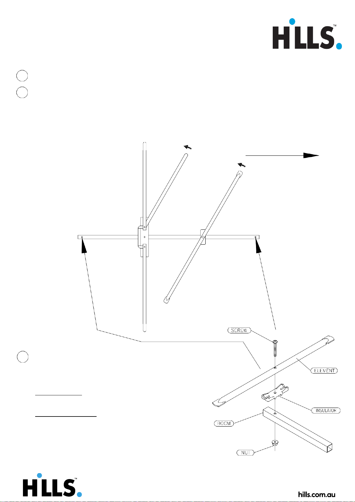
2 Unfolding the Antenna.
Starting at the back of the antenna and working towards the front... grasp
each element close to the pivot point (within 300mm) and rotate outwards
until it clicks firmly into place. (see Figure 1)
FIGURE 1
TOWARDS TRANSMITTER
Back Front
3 Loose Element Assembly.
*Note: Excludes Y3FM model.
Remove the loose straight elements from antenna along with
the screws, nuts & insulators from the accessory bag.
For DY models: Position short element at front & long
element at back, (see Figure 1).
For all other models: Position loose element at front
of antenna, (see Figure 1).
Place screw through the element, insulator & boom,
affix and tighten the nut, (see Figure 2).
FIGURE 2
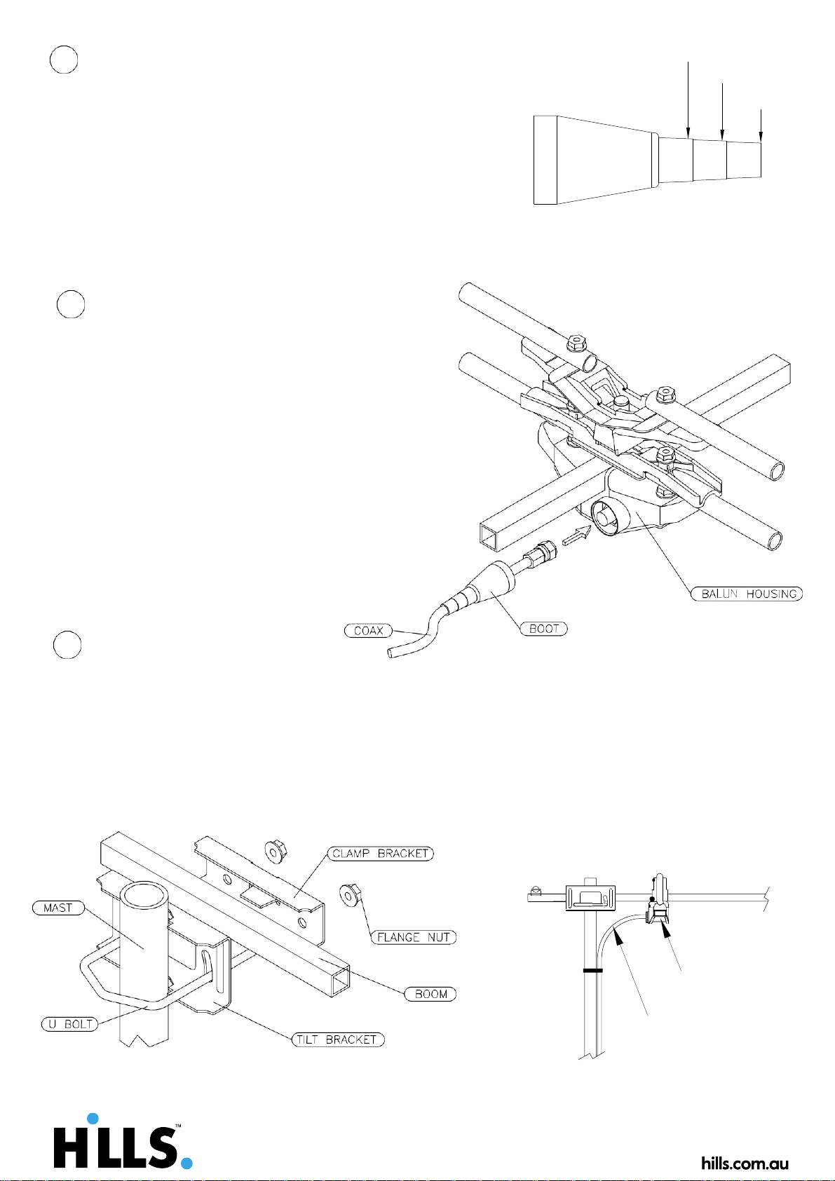
Boot Preparation.
The boot has been designed to suit various sizes
of cables. For RG59 cable no trimming is necessary.
But for other cables trimming is required to suit. Refer
to Figure 3 showing appropriate positions for trimming
for correct coax cable type. When trimming boot
ensure a neat fit around cable to minimise water ingress
RG6 QUAD
FIGURE 3
Coax Cable Connection.
Slide the rubber boot provided down the
Coax Cable then fit the F Type connector
to the end of the Cable.
NOTE: the F type connector is not provided and
will depend upon the type of Coax Cable used.
(see Figure 4).
Pull enough cable through to reach
the balun housing and screw on connector.
Note: do not over tighten F Type connector.
Slide the boot down the Coax Cable into the
housing to cover the F connector. (see Figure 4)
FIGURE 4
Mounting the Antenna.
Check and ensure all fasteners are tight before mounting the antenna.
Assemble the mounting bracket and slide on to the boom. Loosen the flange nuts
sufficiently to allow the mast to fit between the tilt bracket and the U bolt.
Slide the antenna over the mast and tighten the nuts finger tight. (see Fig. 5)
Make sure balun housing is on the bottom side of the antenna. (see Fig. 6)
Aim the antenna towards the transmitter and tighten the nuts with a spanner.
Secure the cable to the mast with suitable fasteners such as cable ties or tape.
INSTALLATION TIPS : For best results mount the antenna outdoors, clear of any
obstructions and in line of sight with the transmitter.
TOP
FIGURE 5
FIGURE 6
RG6 DUO
RG59
Balun Housing
Avoid sharp bends
in the Coax Cable
6
5
4
 Loading...