

Hills VoiceNav Installation Manual


Installation
Remove the cap that’s covering the locking mechanism, this is located on the
bottom of the VoiceNav. With the cap removed you now have access to the
locking mechanism that secures your VoiceNav to its mounting plate. Insert a
small flat head screwdriver until it is located under the locking tongue.
Whilst turning either clockwise or counter clock wise, slide the VoiceNav down
and clear of the locking tongue, you can now remove the VoiceNav from its
mounting bracket. Use the fixings supplied to secure the mounting plate to the
wall. The top of the Voicenav will be 9mm above the top of mounting bracket after
it is locked back in place.
9mm
Rear view showing cable header pins
2

Wiring Structure Note
Note: Both the audio line and data bus line can either be star or daisy chain wired. A maximum of 8 VoiceNav’s can be
configured as room stations for intercom functionality. Two pairs of twisted cable (4 conductors) are required for the
audio line, one pair for audio line A and another for audio line B.
Recordings are transferred between VoiceNav’s via the audio lines and accessory S1931A ‘Voicenav copy cable” was
specifically designed to transfer these recordings in installations that do not have dedicated audio cables installed,
please contact your local DAS branch for further details.
The audio line is not connected to the security panel.
HILLS VOICENAV INSTALLATION MANUAL V0.8 www,das.com.au
3
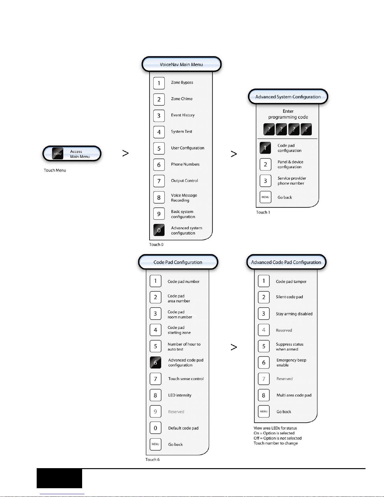
Advanced System Configuration uration
HILLS VOICENAV INSTALLATION MANUAL V0.8 www,das.com.au
4
 Loading...