

Page 1
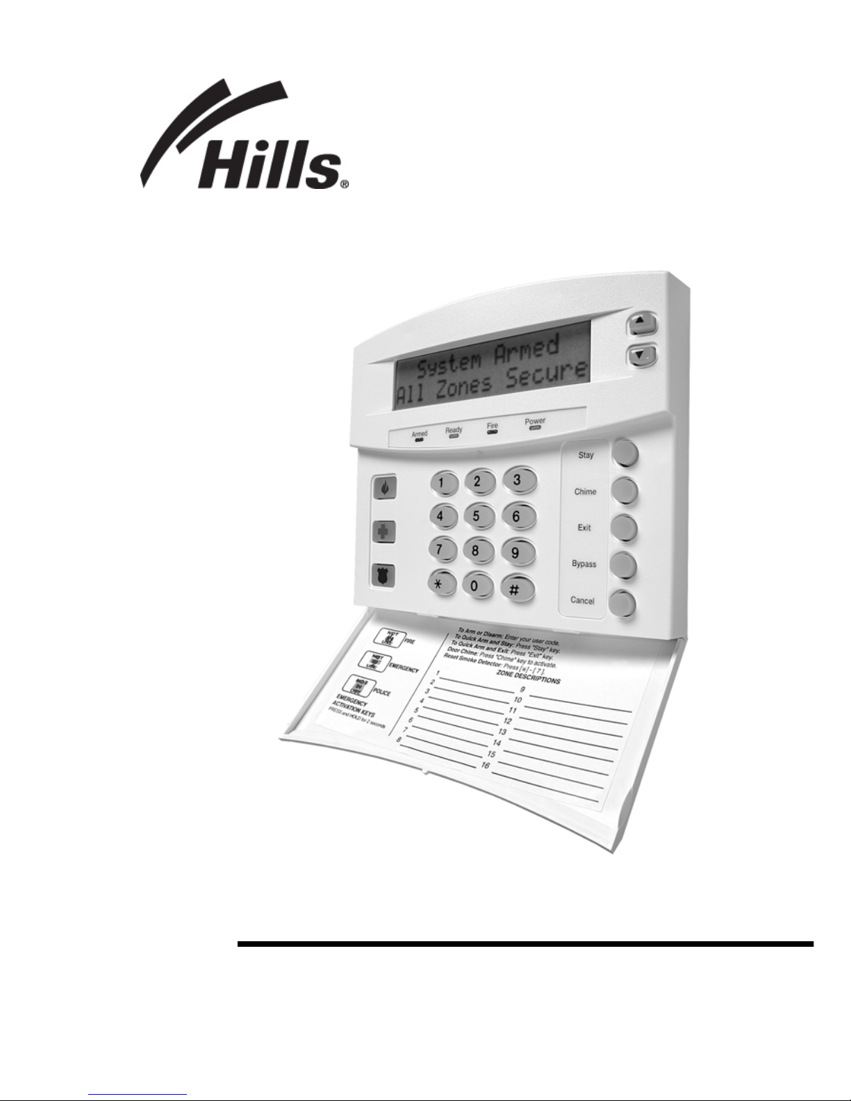
HILLS® Series LCD Code Pad
User Manual
Page 2

THIS MANUAL IS FURNISHED TO HELP YOU UNDERSTAND YOUR SECURITY SYSTEM
AND BECOME PROFICIENT IN ITS OPERATION. ALL USERS OF YOUR SECURITY
SYSTEM SHOULD READ AND FOLLOW THE INSTRUCTIONS AND PRECAUTIONS IN
THIS BOOKLET BEFORE OPERATING YOUR SECURITY CONTROL SYSTEM. FAILURE
TO DO SO COULD RESULT IN THE SECURITY SYSTEM NOT WORKING PROPERLY.
THIS BOOKLET SHOULD BE KEPT IN AN ACCESSIBLE LOCATION FOR THE LIFE OF
THE SECURITY SYSTEM. IF YOU DO NOT UNDERSTAND ANY PART OF THIS
MANUAL, YOU SHOULD NOTIFY YOUR INSTALLING COMPANY. READ THE ENTIRE
MANUAL AND, IF POSSIBLE, PRACTICE ON THE KEYPAD CONTROL WHILE YOUR
PROFESSIONAL INSTALLER IS ON SITE.
The SECURITY CONTROL can be turned on (ARMED) and off (DISARMED) by entering a 4
or 6 digit code into the Keypad Control, which is similar to a telephone keypad. If your
Security Control has been so programmed, you may be able to turn on (ARM) y our System by
simply pressing the [STAY] or [EXIT] key. The system must always be Disarmed using a 4 or
6 digit code. The LCD keypad includes 9 lights and a 32-character liquid crystal display and a
built-in electronic sounder. These provide specific information relating to the status of the
security system which is described in the booklet. Understanding what the lights and sounds
mean will help you to easily operate your system.
KEEP IN MIND, THE LEVEL OF SECURITY YOU WILL OBT AIN WITH THIS SYSTEM
RELATES SPECIFICALLY WITH TWO MAJOR FACTORS:
1. The quantity, quality, and placement of security devices attached to this system.
2. The knowledge you have of the security system and how that knowledge is utilized
in a weekly test of the complete system.
YOU SHOULD BE AWARE OF THE FOLLOWING FACTS WHEN PREPARING A
SAFETY/SECURITY PLAN FOR YOUR HOME/BUSINESS.
1. Your security system is an electronic device and like any electronic device is subject
to failure or malfunction. Do not rely on it as your single source of security.
2. Your system should be tested weekly.
3. Your system will not work without power.
4. Warning devices will need to be loud enough, wired correct ly, and properly placed to
provide notification of an alarm event.
5. Smoke and heat detectors may not detect heat and smoke in all situations.
6. Use qualified security professionals to install and maintain your security system.
7. It may be possible to arm the security system without the backup battery connected.
Your periodic test should be done with A.C. power removed to verify the battery is
connected and adequately charged.
8. Care should be taken to plug in and restrain the A.C. Transformer after testing.
This product is to be installed by quali fied SERVICE PERSONNEL only
The equipment should only be operated with an approved power adapter with insulated
live pins.
CAUTION – RISK OF EXPLOSION IF BATTERY IS REPLACED BY AN INCORRECT
TYPE. DISPOSE OF BATTERIES ACCORDING TO THE INSTRUCTIONS. CONTACT
YOUR INSTALLER FOR REPLACEMENT BATTERIES.
When installed as directed, this product co nforms to the sta ndards
set by Standards Australia on behalf of the Australian
Communications Authority (ACA)
Page 3

TABLE OF CONTENTS
I.
GLOSSARY OF TERMS.........................................................................3
II.
UNDERSTANDING THE LIGHTS...........................................................4
III.
KEYPAD FUNCTIONS............................................................................5
ARMING YOUR SYSTEM IN THE “AWAY” MODE.................................5
MAKING YOUR SYSTEM READY TO ARM...........................................5
ARMING YOUR SYSTEM IN THE “STAY” MODE..................................6
USING THE QUICK ARM........................................................................7
CHANGING MODES WHILE YOUR SYSTEM IS ARMED .....................7
DISARMING YOUR SYSTEM.................................................................7
CANCEL / ABORT FEATURE (O
PTIONAL, IF PROGRAMMED
) ....................8
BYPASSING ZONES ..............................................................................8
GROUP BYPASS.................................................................................... 9
UNBYPASSING ......................................................................................9
EMERGENCY ACTIVATION KEYS ........................................................9
FUNCTION MENU ................................................................................10
VIEW ZONE STATUS...........................................................................11
SETTING THE KEYPAD TONE............................................................11
VIEW ALARM MEMORY.......................................................................11
TEST FUNCTION (O
PTIONAL, IF PROGRAMMED
)......................................11
DISPLAY TEST FUNCTION..................................................................12
LIGHT CONTROL FOR X-10 DEVICES (O
PTIONAL, IF PROGRAMMED
)....12
CHANGE LANGUAGES........................................................................12
CHANGING USER CODES ..................................................................13
ASSIGNING USER CODE AUTHORITY LEVELS................................13
RESET FUNCTION...............................................................................14
READING THE EVENT LOG ................................................................15
ADJUSTING THE VIEW / BRIGHTNESS OF THE LCD .......................15
SETTING THE SYSTEM CLOCK..........................................................16
USING THE DOOR CHIME FEATURE.................................................16
IV.
PARTITIONED SYSTEMS OPERATION..............................................17
LIGHTS IN PARTITIONING MASTER MODE.......................................17
DISPLAYS IN THE PARTITIONING MASTER MODE..........................18
V.
KEYPAD CONTROL TONES (BEEPS).................................................20
VI.
SERVICE DISPLAY...............................................................................21
VII. APPENDIX A - EVENT LOG.................................................................23
VIII. EMERGENCY EVACUATION PLANS ..................................................25
Hills LCD Keypad
1
Page 4

WARRANTY
Hills Industries guarantees this product against defective parts and workmanship
for twenty-four (24) months from the date of purchase. If any defect appears during
the warranty period return it to place of purchase. Hills Industries assumes no
liability for consequential or indirect damage and accepts no responsibility for
repairing damage to the product caused b y misuse, careless handl ing, or where
repairs have been made by others.
No other guarantee, written or verbal, is authorized by or on behalf of Hills
Industries.
Hills LCD Keypad
2
Page 5

I. GLOSSARY OF TERMS
Abort Delay: An option that allows a delay in reporting to the central
station.
Authority Level: The level of access an individual has when using an alarm
panel.
Central Station: Location where alarm data is sent during an alarm report.
Chime Feature: An option that allows the keypad to sound a ding-dong
whenever an entry/exit door is opened.
Codes: Can be either User Codes (relating to a person) or Function
Codes (a toggle switch to turn specific functions on/off).
NOTE: A system may have either four (4) digit codes or
six (6) digit codes, but not a mixture of the tw o.
Duress Code: An option that allows a special code to be sent to the
central station that indicates the alarm system is being
operated under duress.
Forced Arming: An option that allows the system to be turned on (ARMED)
with one or more zones open. A system that is ready to be
“force armed” will flash the ready light. NOTE: Those
zones that are not ready will not create an alarm.
Function Code: A Function Code is either a four (4) or six (6) digit code that
has been programmed by the installer to operate a device.
Group Bypass: An option that allows the user to bypass multiple zon es with
a single operation.
Instant/Delay: An option that allows an instant alarm condition for
Entry/Exit doors, or grants a delay to allow someone to
enter/exit the building without an alarm or before entering a
user code to disarm.
Master Code: A master arm/disarm code that can program other user
codes.
Partitioned System: A system divided into mu ltiple areas in which its own user
or users control each area.
Perimeter: The outer edge of the protected area.
Quick Arm: An option that allows you to turn on (ARM) the security
system by pressing either the [STAY] or [EXIT] key on the
keypad control (for ARMING only) as progr ammed by the
installing company.
User Code: A four (4) or six (6) digit entry used to arm or disarm the
system.
Hills LCD Keypad
3
Page 6

II. UNDERSTANDING THE LIGHTS
Armed Light The armed light is “on” when the system is armed. The armed
light is “off” when it is disarmed. The armed light will flash
when there has been an alarm during the previous arm cycle.
Bypass Light The bypass light is “on” when any zone in this keypad’s
partition is bypassed. If the bypass light is “off”, no zones are
bypassed.
Cancel Light The cancel light will flash during an abort delay time. Entering a
code followed by the [CANCEL] key during or after an alarm
report to the central station will cause the cancel light to come
on. It will stay on until the central station has received the
cancel report. NOTE: The cancel feature must be enabled.
(See "Cancel/Abort Feature" on page 8.)
Chime Light The chime light is “on” when the chime feature is “on”; “off”
otherwise.
Exit Light The exit light is “on” during the exit delay. Please note that the
light will flash during the last 10 seconds of the exit delay as a
warning that the time is running out. (The u ser may want to
disarm the system if the exit light is flashing in order to
prevent an alarm. The user may then re-arm the system and
exit before the delay expires.)
Fire Light A steady fire light means a fire zone has been faulted. A rapidly
flashing fire light means that a fire zone is in a trouble
condition.
Power Light The power light is on if the primary power is on. The power light
will flash if the system has a low battery condition.
Ready Light The ready light is “on” when the system is ready to arm and
“flashes” if ready to force arm. The ready light is “off” when the
system is not ready to arm because of a zone(s) being
faulted.
Stay Light The stay light is illuminated when
all interior zones are
bypassed.
Instant Message The LCD display will read “Instant“ when the entry/exit door(s)
have no delay. (See “Arming System in Stay Mode”, page 6.)
The doors can be changed from instant to delay (toggled) by
pressing the [STAY] key when the system is armed.
Hills LCD Keypad
4
Page 7
III. KEYPAD FUNCTIONS
ARMING YOUR SYSTEM IN THE “AWAY” MODE
AWAY is utilized when the user is going away from the premise and wants the
interior protected. Listed below are the steps to arm in the AWAY Mode:
Step 1 Close all protected doors and windows.
Ready light will be on or
flashing when all protected
zones and sensors are
secure. NOTE: If any zones
are bypassed, a sensor in
that zone can be violated without affecting the ready light.
The security system will not
arm if the ready light is off.
Refer to "Making Your
System Ready to Arm".
If the power light is off, you have no AC power. Restore power if
possible. If not, contact the installing company.
Step 2 Enter your 4 or 6 digit user code to arm the system.
The armed and exit lights will
illuminate.
You may now leave the building.
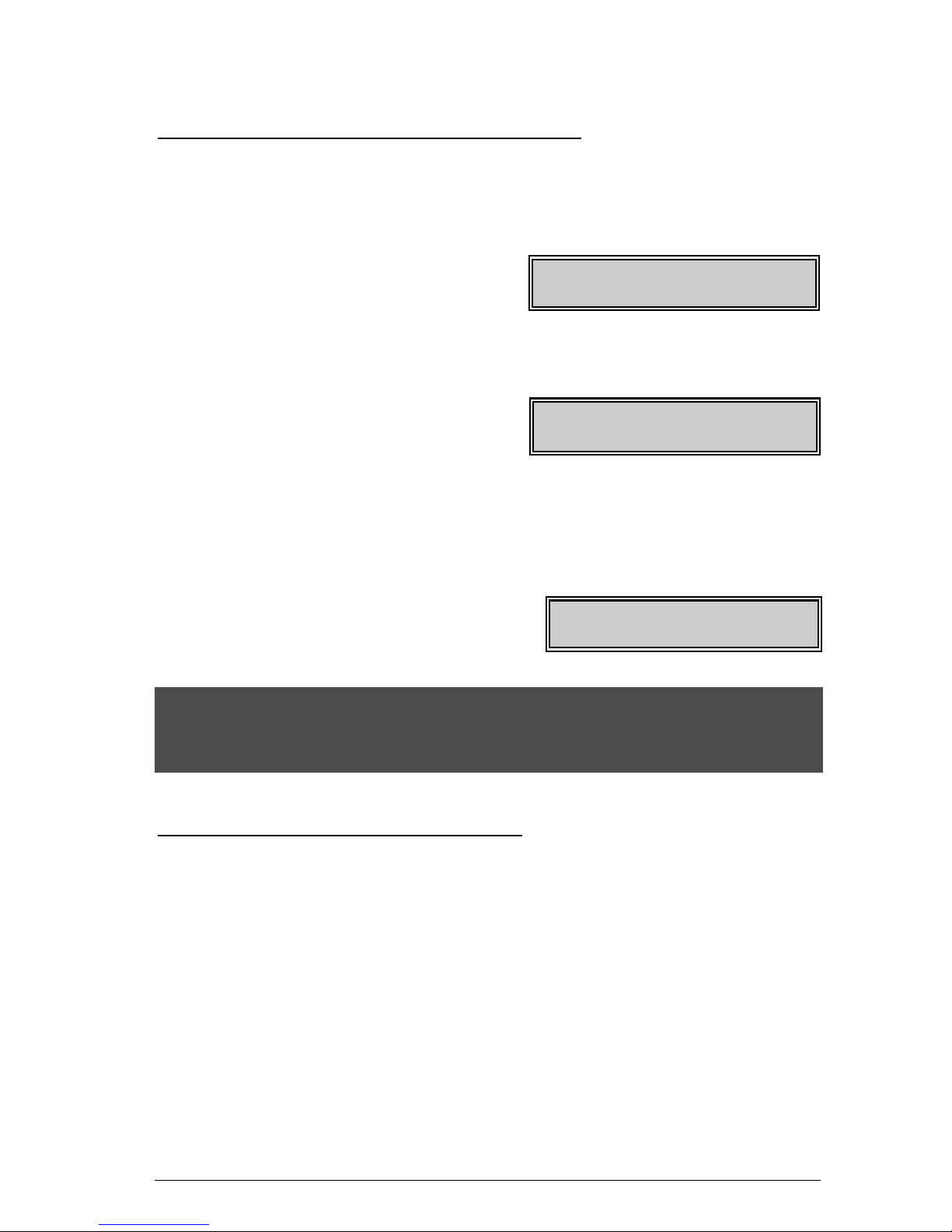
System Ready
Type Code to Arm
System Not Ready
For help, press º
System Armed
All Zones Secure
IMPORTANT!
The exit light will flash rapidly for the last 10 seconds of the exit delay as a
warning to the user that the exit time is about to expire. The user may wish to
disarm and rearm the system if more time is needed.
MAKING YOUR SYSTEM READY TO ARM
If the ready light is not on or if it is flashing, a zone is not s ecure. T o ide ntif y this
zone, use the scroll keys • – to the right of the display to browse through the
zones that are not normal. If you wish to bypass or unbypass one of these zones,
press the [BYPASS] key while that zone is being displayed. When finished viewing
the zones, press the # key to return to the code entry screen.
Hills LCD Keypad
5
Page 8

ARMING YOUR SYSTEM IN THE “STAY” MODE
STAY is utilized when the user is inside the premise and wants protection around
the perimeter. The steps to arm in the STAY Mode are as follows:
Step 1 Close all protected doors and windows.
Ready light must be on or flashing (force armed) when all protected
zones and sensors are secure. NOTE: If any zones are bypassed, a
sensor in that zone can be violated with out affecting the ready
light.
The security system will not arm if the ready light is not on or flashing.
If the power light is off, you have no AC power. Restore power if
possible. If not, contact the installing company for service.
Step 2 Enter your 4 or 6 digit user code. (Optional, if programmed.)
If “Auto Bypass” is enabled, all interior zones will be bypasse d if you
do not leave through a designated entry/exit door. If Auto Bypass is
enabled, omit Step 3.
When “Auto Instant” is enabled, if you do not leave through a
designated entry/exit door, the d isplay will read “Instant”, indicating
that the entry/exit doors no longer have an entry delay. If “Auto
Instant” is enabled, omit Step 4.
Step 3 Press the [STAY] key.
The stay light will illuminate indicating that all interior zones are
bypassed. (All interior devices will bypass automatically, giving the
user freedom of movement within the interior area.)
The bypass light will illuminate if any zone(s ) are bypassed. If any
zone (s) have been bypassed previously by the user, the light(s)
corresponding to the bypassed zone(s) will illuminate, alerting the user
that a zone(s) may be unprotected and can be faulted without an
alarm.
Step 4 To toggle from a “delayed entry” mode to an “Instant” mode, press the
[STAY] key again.
The LCD display will read
“Instant” meaning the entry/ exit
doors do NOT have an entry
delay.
System Ready
Type code to arm
System Armed
Instant
Hills LCD Keypad
6
Page 9

USING THE QUICK ARM
The Quick Arm feature may be used if it is enabled. Quick Arm will allow the us er to
arm the security system in the AWAY mode by pressing the [EXIT] key. The
system can be quick armed in the STAY mode by pressing the [STAY] key. This
feature is used for ARMING ONLY, and will not disarm the security system. This is
ideal for a maid or baby sitter code, etc.
CHANGING MODES WHILE YOUR SYSTEM IS ARMED
Step 1 Pressing the [STAY] key will turn on/off (toggle) a delay on Entry/Exit
doors. The “Instant” message will toggle on the LCD display.
Step 2 (Optional, if programmed.) Press the [BYPASS] key at this time to turn
on/off (toggle) all designated interior zones. If all interior zo nes are not
bypassed, the stay light will extinguish.
Step 3 (Optional, if programmed.) When armed, pressing the [EXIT] key will start
the Exit delay, enabling you to leave the building.
IMPORTANT!
An alarm will be created if the “Instant” message is ON at this time and you re-enter
the building. You may re-initiate an entry/exit delay by pressing the [STAY] key
again. The “Instant” message will disappear.
DISARMING YOUR SYSTEM
When you enter the protected area through one of the designated Entry/Exit doors,
the keypad control will sound a continuous tone for the duration of the entry delay
time, or until you enter a valid code.
Type code to
Disarm
Step 1 Enter a valid user code.
Step 2 The red armed light will go off and the tone will stop. The security system
is now DISARMED. If a valid code is not entered before t he end of the
entry delay, an alarm will occur. NOTE: If the red armed light is
flashing during the entry delay, the alarm system has been activated
in your absence. Leave the buildin g immediately and call your ala rm
company and/or the police from a safe location.
Hills LCD Keypad
7
Page 10

CANCEL / ABORT FEATURE (Optional, if programmed)
The cancel light will flash during an abort delay time. If a code is entered followed
by the [CANCEL] key while this light is flashing, all abortable reports will stop the
communication process. NOTE: The abort feature must be enabled. Entering a
code followed by the [CANCEL] key during or after an alarm report to the central
station will cause the cancel light to come on. It will stay on until the central station
has received the cancel report. NOTE: The cancel feature must be enabled.
BYPASSING ZONES
If you wish to bypass one or more zones, this must be done while the system is in
the disarmed state. If the zone is not known, refer to Procedure #2.
Procedure #1
If you know the number of the zone to bypass, use the following:
Step 1 Press the [BYPASS] key.
Step 2 When the LCD prompts for a code (optional, if programmed), enter your
user code.
Step 3 The bypass light flashes.
Step 4 Enter the zone you wish to bypass. (Example: Press 6 for zone 6 or
1 1 2 for zone 112.)
Step 5 Press the [BYPASS] key again. The zone is now bypassed.
Step 6 Repeat steps 4 and 5 for any other zone(s) that need to be bypassed.
Step 7 Press the [BYPASS] key again OR press # to exit the Bypass Mode.
The bypass light will stop flashing upon exiting the Bypass Mode.
Pressing the • – scroll keys will display all bypassed zones. Press
the # key to exit this viewing mode.
Hills LCD Keypad
8
Page 11
Procedure #2
If you do not know the number of the zone you wish to bypass,
use the following steps:
Step 1 Press r • The description for zone 1 will be displayed.
Step 2 Use the • – scroll keys to browse through the custom descriptions
for the zones in this system.
Step 3 To bypass or unbypass a specific zone, press the [BYPASS] key while
that zone is displayed.
Step 4 When finished, press the # key to return to the code entry screen.
GROUP BYPASS
By pressing the [BYPASS] key, followed by the 0 key, then the [BYPASS] key
again, all zones that are designated as group bypass zones will be bypassed.
Press the [BYPASS] key again to exit group bypassing.
UNBYPASSING
To manually unbypass zones, perform the bypassing procedure on a zone that is
already bypassed. NOTE: All zones will automatically be unbypassed each time
the system is disarmed.
EMERGENCY ACTIVATION KEYS
NOTE: You must press and hold these keys for 2 seconds to activate these
functions. Your system may not be programmed for these activations.
Fire Key - If programmed, you can activate the Fire alarm by pressing the
Emergency Activation [Fire] key for two seconds. If your system is connected to a
monitoring center, an emergency report could be sent to that center. This key
should only be pressed in an emergency situation requiring response by fire
department personnel.
Hills LCD Keypad
9
Page 12
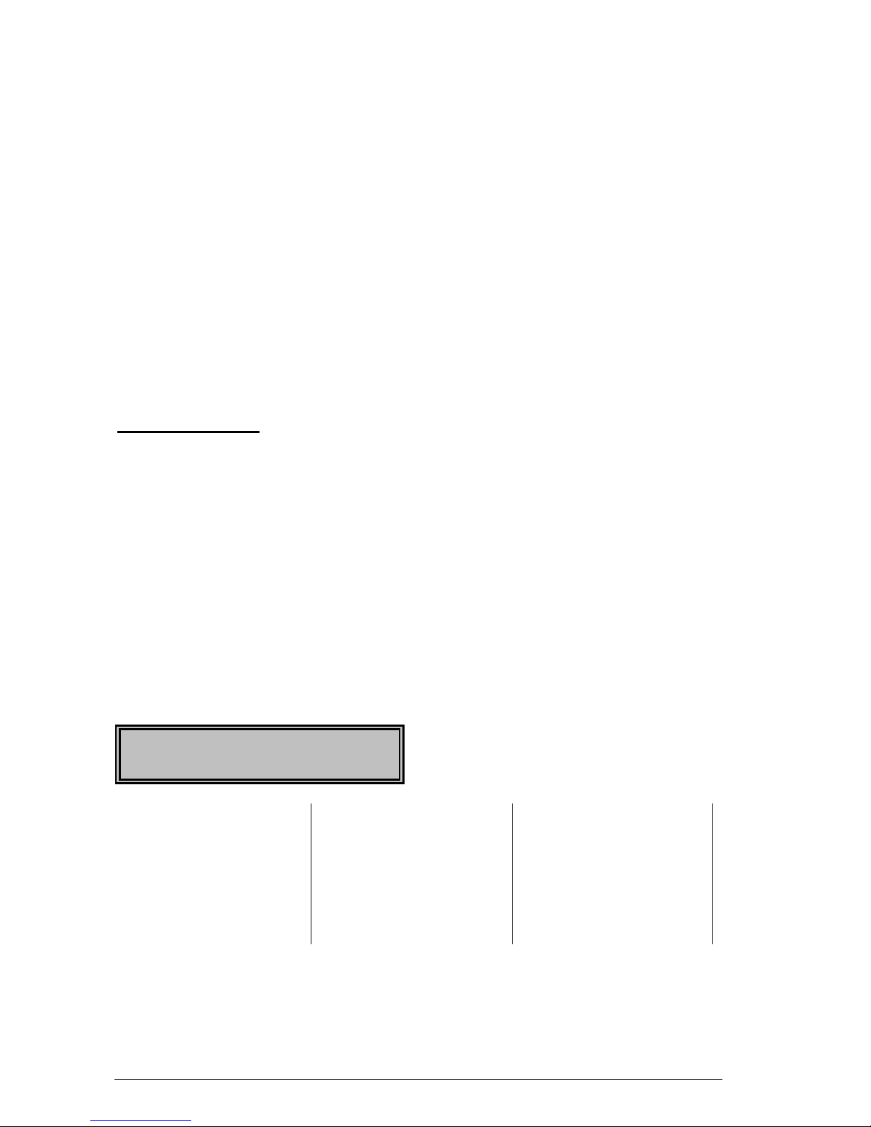
Auxiliary Key - If programmed, you can activate the auxiliary alarm by pressing the
Emergency Activation [Auxiliary] key for two seconds. If your system is c onnected
to a monitoring center, an emergency report could be sent to that center. This key
should only be pressed in an emergency situation requiring response by
emergency personnel.
Police (Panic/Hold-Up) Key - If programmed, when the Emergency Activation
[Police] key is pressed for two seconds, a local audible alar m will sound. If your
system is connected to a monitoring center, an emergency report could be
transmitted to that center. These keys shou ld only be pres sed in an emergenc y
situation requiring immediate response by law enforcement personnel. NOTE:
Some Panic/Hold-Up alarms are programmed to b e silent at the protected site
while reporting an alarm to the monitoring center. Check with your installing
company to determine how your security system will respond to the Panic/Hold-Up
activation.
FUNCTION MENU
The functions listed below are found in the Function Menu.
Step 1 Press r The display will now begin scrolling though a list of functions
and the corresponding numbers associated with those functions.
Step 2 Press the number listed on the display in ord er to access th at partic ular
function. Hint: If you already know the function numbers simply press [r] followed
by the function number.
The following list of menu selections will scroll automatically. NOTE: Some of the
functions are not listed because they are installer level functions. Each time the [r]
key is pressed the next menu item will be displayed. Press # to exit to this
menu.
This is a sample of the display. The list
below reflects the available functions.
Select an Option
Press À for Hel
p
ù=Zone Review
45=Display Test 90=Log Review
0=Set Tone 46=Light Control 91=View Settings
1=Master Mode
49=Español
97=Set Date/Time
2=Service Check 5=User PIN CHIME=Walk Test
3=Alarm Memory 6=User Authority EXIT=Silent Exit
44=Test 7=Detector Reset
Hills LCD Keypad
10
Page 13
VIEW ZONE STATUS
Step 1 Press r • . The LCD Screen will display the zone status.
Step 2 Use the up and down scroll keys to browse through the descriptions. The
LCD Screen will display the list of all zones in seque ntial order by zone
number.
Step 3 Press [#] to exit this function.
SETTING THE KEYPAD TONE
Step 1 Press r 0 . Keypad is now in the “Adjust Tone” mode.
Step 2 Press the • up scroll key located
on the right side of the display to
adjust the keypad sounder to higher
tones.
Step 3 Press the – down scroll key to adjust the keypad sounder to lower tones.
Step 4 When the desired tone is reached, press # to set this tone and exit from
the “Adjust Tone” mode.
VIEW ALARM MEMORY
Step 1 Press r 3 to display the zone(s) on the keypad that created the last
alarm.
Raise tone º
Lower tone º
Alarm Memory 1
ZONE 1
Step 2 The LCD Screen will display the
zone description for those zones.
Step 3 Press [#] to exit the alarm memory.
TEST FUNCTION (Optional, if programmed)
If programmed, this function will perform a b attery test, communicator te st, and/or a
siren test. No alarms will be sent, and no reports will be sent unless a
communicator test is performed, in which case a test signal will be sent.
Step 1 Press r 4 4 . The test will be performed as programmed.
Step 2 If the siren test is performed, enter a user code to silence the siren.
Hills LCD Keypad
11
Page 14

DISPLAY TEST FUNCTION
This function will perform a test of the LCD display. No alar ms or reports will be
sent.
Step 1 Press r 4 5 . The test will be performed and all of the d isplay
pixels and LED indicators will flash until another key is pressed.
Step 2 Press any key to end the test.
LIGHT CONTROL FOR X-10 DEVICES (Optional, if programmed)
This menu allows you to control up to ten X-10 devices from each keypad.
Step 1 Press r 4 6 . The LCD screen will prompt you to “Select Li ght
Number 0 - 9”.
Step 2 Enter the number of the X-10 device you want to control. The LCD screen
will show the light number on the left. On the right side of the display it will
prompt you to turn the light (X-10 device) “On” or “Off”.
Step 3 Press the • to turn the X-10 device “On” or press the – to turn the X-
10 device “Off”.
Step 4 The LCD screen will again prompt you to “Select Light Num ber 0 - 9”.
Step 5 Repeat Steps 2 and 3 until complete.
Step 6 Press # to exit from the X-10 menu.
CHANGE LANGUAGES
This function allows you to switch between the two languages programmed in your
keypad. NOTE
: You must exit any other function mode before attempting to
change languages.
Step 1 Press r 4 9 . T he LCD keypad is now toggled to the second
language.
Step 2 Repeat Step 1 to revert to the first language.
Hills LCD Keypad
12
Page 15

CHANGING USER CODES
Step 1 Press r 5 . The LCD Screen will prompt for a code.
Step 2 Enter [master code]. The LCD Screen will prompt for a user number.
NOTE: For partitioned systems, if you are changing the code of
another person, you must have access to all partitions, or at least all
of the partitions to which the other person has access.
Step 3 Enter the 2-digit (applies to NX4/6/8) or 3-digit (applies to NX8E) user
number. Always use leading zeros when necessary, i.e. "004" for user
number 4.
The LCD keypad will display the current code for this user. Stars (r)
represent blanks. NOTE: To delete
a user code, press [r]-[r]-[r]-[r] for
a 4-digit code or [r]-[r]-[r]-[r]-[r]-[r] for a 6-digit code.
Step 4 Enter the new user code for that individual. If you are changing the
current code, you may use the up and down scroll keys to select the digit
to change and enter the correct number. If it rejects the code because of
duplication or such, the sounder will beep 3 times.
Step 5 If another user code needs to be programmed, return to step 3 and enter
the user code.
Step 6 To exit Code Programming, press # while the screen is prompting for a
new user.
ASSIGNING USER CODE AUTHORITY LEVELS
Assign authority levels to user s b y following the steps below. Assign user codes
before assigning authority levels.
NOTE: You must have authority to the partition you w ish to add or remove
from another person’s authority.
Step 1 Press r 6 . The LCD Screen will now prompt for a code.
Step 2 Enter [master code]. The LCD Screen will prompt for a user number.
Step 3 Enter the 2-digit (applies to NX4/6/8) or 3-digit (applies to NX8E) user
number. Always use leading zeros when necessary, i.e. "004" for user
number 4. The LCD will now prompt you for the attributes in the following
chart.
Hills LCD Keypad
13
Page 16
PROMPT
Outputs used? » DO NOT CHANGE THIS SEGMENT!
Open / Close Rprt?
Bypass enable?
Arm / Disarm?
(These are for use by a professional installer only.)
Master code?
Sched arm only?
Arm only?
Reserved
0=No 1=Yes
Your key press will apply to the user code you entered in
Step 3.
Output 4 ?
Output 3 ?
Output 2 ?
Output 1?
If these messages appear on the LCD screen, press the [r]
key until you return to the prompt for the user code or until
you exit this adjust mode.
Step 4 NOTE: The LCD will now display all of the partitions to which this user
has access. If you wish to remove a partition, press the partition number
on the keypad, and the display will mark that partition with a (-) hyphen
indicating access has been removed. If you wish to re-establish user
access to the partition, press the partition number again.
Step 5 Press r to save the d ata. The LCD will then prom pt you for the next
user code.
Step 6 If another user code needs to be programm ed, return to Step 3. If not,
press # to exit this feature without saving the data.
RESET FUNCTION
This function is used to reset Smoke Detectors, Zone Troubles, and Zone
Tampers.
Step 1 Disarm the system if it is not already disarmed.
Step 2 Press r 7 . Resets have now been performed.
Step 3 If the keypad begins beeping, the reset did not execute properly. Enter
your code to silence the keypad. Wait a few minutes and repeat step 2
to attempt another reset. If the keypad still beeps after repeated
attempts, please contact your installer.
Hills LCD Keypad
14
Page 17

READING THE EVENT LOG
The control panel has an event log that can be retrieved using a master code. This
log contains a listing of the events along with date, time, and partition where the
event occurred.
Step 1 To view the log, press r 9 0 . The LCD screen will prompt you
for a code.
Step 2 Enter your master code. The LCD screen will now show the most recent
event.
Step 3 To view the events from most recent to the oldest, press – .
Step 4 To view the events from the oldest to the newest, press • . The display
contains the following information.
Event ¼ » User or Zone ID
Date ¼ » Indicates partition
Open 75
9/25 17:57 P3*
(Month/Day)
ü Time shown in and À indicates an
24-hour format event not reported
This screen shows an opening of Partition 3 on S eptember 25
th
at 5:27 p.m. by
user 75. The [r] shows that this event is not pro grammed to be reported to the
central monitoring station. Refer to Appendix A on page 23 for a list of possible log
messages.
ADJUSTING THE VIEW / BRIGHTNESS OF THE LCD
Step 1 Enter r 9 1 . The LCD Screen will prompt for a code.
Step 2 Enter [master code]. The LCD will now prompt you to raise or lower the
view.
Step 3 Using the – • scroll keys to the right of the LCD, you can raise or
lower the viewing angle of the text.
Step 4 To advance to the Brightness option, press r The LCD will prompt you
to brighten or dim the LCD lighting. Use the scroll keys again to adjust to
desired brightness.
Step 5 When completed, exit by pressing r
Hills LCD Keypad
15
Page 18

SETTING THE SYSTEM CLOCK
Step 1 Enter r 9 7 . The LCD Screen will prompt for a code.
Step 2 Enter [master code]. The time and date will be dis played with the
current hour flashing.
Step 3 Use the • – scroll keys to select the proper hour.
Step 4 Press the r key to move to the minutes, day of week, date, month,
and year.
Step 5 Repeat Steps 3 and 4 until the entire time and date are set.
USING THE DOOR CHIME FEATURE
The door chime is turned on or off by pressing the [CHIME] key. If the chime is on,
the chime light will be illuminated. If the chime is off, the chime light will be off.
Each press of the [CHIME] key will toggle the chime feature on/off and produce a
momentary ding-dong sound.
Hills LCD Keypad
16
Page 19

IV. PARTITIONED SYSTEMS OPERATION
This system is “ is not “ partitioned.
If your system is multi-partitioned and the ke ypad resides in one partition, your
keypad will provide the status of the zones in your partitioning by using the screen
messages described earlier in this manual. The Master Mode of operation allows
you to temporarily access any partition (providing your co de is authoriz ed) within
the system and to perform functions in other partitions. Read this entire manual to
help you understand the different screen messages that will be displayed from your
keypad.
NOTE: r 1 will temporarily access the Master Mode. The keypad will revert
back to its assigned partition 60 seconds after a key press, or 10 seconds without a
key press. Press [#] to exit this mode.
LIGHTS IN PARTITIONING MASTER MODE
ARMED will illuminate if ALL
partitions are armed.
READY will illuminate if ALL
partitions are "Ready". The ready light will flash if
all areas are Ready or Force armable.
FIRE will illuminate if ANY one area has a Fire condition. T he fire light will
flash if ANY area has a Fire Trouble condition.
POWER will illuminate if the primary po wer is connected to the NX-8 c ontrol
panel. It will flash if the system has a low standby battery condition.
STAY will illuminate if ANY area has the stay light on.
CHIME will illuminate if ANY partition is in the "Chime" mode.
EXIT will illuminate if ANY area is timing an exit delay. It will flash if ANY area
is in the last 10 seconds of an exit delay.
BYPASS will illuminate if ANY area has a zone bypassed.
CANCEL will flash if ANY partition is in an abort delay time. If a code is
entered followed by the [CANCEL] key during or after an alarm report, the
cancel light will illuminate and remain const ant until the central station has
received the cancel report.
SOUNDER will sound if ANY area has the soun der on. This incl udes Entry
delay, Exit delay, Chime, and Alarm.
Hills LCD Keypad
17
Page 20
DISPLAYS IN THE PARTITIONING MASTER MODE
ARMED and READY STATUS
The LCD screen will display the Armed and Ready status of ALL eight (8)
partitions if any or all of the areas is armed or not ready.
This display is reflecting all 8 areas are
nd Area 5 is disarmed. NOTE: If a
number is flashing on the Armed line, that
area is armed Instant. If a number is flashing
on the Ready line, that area is ready to be
Force Armed.
Ready, a
If ALL areas are disarmed and ready to arm,
this display will appear on the LCD screen.
ARMING AND DISARMING MULTIPLE PARTITIONS
To arm/disarm multiple partitions, enter a code that has arm/disarm authority for
ALL of the partitions to be armed/disarmed. T he following display will appear on
the LCD screen.
The numbers on the top line represent the
disarmed areas to which this code has
access. The numbers on the bottom line
represent the areas that are armed. Refer to
the following table for possible conditions.
Ready 12345678
Armed 1234-678
System Ready
Type code to arm
12-45-78 Disarm º
--3 67- Arm º
LCD DISPLAY FOR AREA
TOP LINE OVER BOTTOM LINE
CONDITION
Blank
Blank
Area Not used or Authorized
Dash (-)
Dash (-)
Area Not Ready
Flashing Area #
Dash (-)
Area Ready to Force Arm
Dash (-)
Flashing Area #
Area Armed Instant
Area #
Dash (-)
Area Disarmed & Ready to Arm
Dash (-)
Area #
Area is Armed
Hills LCD Keypad
18
Page 21
To disarm all of these areas, press • .
To arm all of these areas, press – .
To toggle a single area b etween the armed and disarmed conditions, press
[À][Area number]. For example: If Area 4 is armed, [À] [4] will disarm Area
4. If Area 4 is disarmed, [À] [4] will arm it.
Press [STAY] during the exit delay to bypass all interior zones in the exit
delay.
To control the individual ar eas, refer to the following section.
OPERATING INDIVIDUAL AREAS IN THE MULTI-PARTITION MODE
Enter a code that is a valid arm/disarm code for the area you wish to operate. The
following display will appear on the LCD screen.
Only the areas authorized by this code will
appear.
To toggle between the armed and disarmed states of an individual area, press [r]
[Area number].
To operate an individual area, enter the number o f the partition you wish to operate.
The LCD keypad will now operate as a single area keypad. All keys and functions
entered will affect this individual partition only. The lights and display represent the
status of that partition only. The word "System" will be replaced with the word
"Area #". The following is an example of this feature. To exit this screen, press [#].
12-4—78 Disarm º
--3-56-- Arm º
Area 5 Ready
Type code to arm
Area 5 is selected and Area 5 is ready to
arm. To exit the individual partition mode,
enter [#]-[#].
SILENCING ALARMS IN THE MULTI-PARTITION MODE
If the keypad is sounding an alarm or the siren is running, it can be silenced by
entering a code with the authority for the area(s) that are in alarm. NOTE: The
[EXIT], [BYPASS], and [STAY] keys will only work if an ind ividual partiti on is
selected.
Hills LCD Keypad
19
Page 22

V. KEYPAD CONTROL TONES (BEEPS)
A sounder is built into the keypad and may sound for any of the following
reasons:
Beeps for all key presses.
Sounds a continuous tone during the Entry delay time.
Pulses when a day zone is violated while the system is disarmed.
Pulses when a FIRE zone has a trouble condition.
Pulses when the armed status changes and the AC po wer is off.
Beeps 3 times for trying to arm with the “READY” light off, if “FORCE
ARMING” has not been selected.
Beeps 1 second for the ‘CHIME” feature.
Beeps 1 second at the end of the exit dela y.
Beeps to indicate telephone li ne fault if sel ected.
Beeps during an exit delay; beeps rap idly for the last 10 seconds of
an exit delay; and beeps 1 second at the end of the exit delay.
Pulses when one or more of the following conditions are detected:
Zone or Box Tamper, Low Battery, AC Power Fail, or Expander
trouble.
Beeps 3 times every minute indicating a l ow battery or missing
transmitter is detected (if wireless device is in system). Entering code
will suppress the sounder for 12 hours.
Entering a valid code will silence the keypad sounder when it is pulsing. The
arm/disarm state of your system will not change when entering a code to silence a
pulsing keypad sounder. Please contact your installer if a trouble condition exists.
Hills LCD Keypad
20
Page 23
VI. SERVICE DISPLAY
The following message will be displayed periodically if the security system requir es
service. Call your service provider promptly if this message is observed.
Service Required
Type r2 for help
If you see this display, press r 2 One or more of the following fault messages
will be displayed. Use the scroll keys • – to browse through them. To exit
the service messages, press [#]-[#].
Control
Box tamper
(Optional) The Box Tamper circuit has
activated.
Control
Fail to Comm.
The control attempted to communicate
a message to the Central Station, but
was unsuccessful.
Control
Ground fault
A short to ground has been detected on
a control circuit.
Control
Loss of time
Your system has lost total power and
needs the clock reset.
Control
Low Battery
The standby battery is low.
Control
Over-current
A short circuit of a control’s power
supply has occurred.
Control
Phone trouble
The phone line connected to the control
is not operating properly.
Control
Power trouble
The main power to your system is not
on.
Control
Siren trouble
Open circuit has occurred on the bell or
siren circuit.
Expansion
Aux. comm. fail
An auxiliary reporting device has failed
to communicate.
Hills LCD Keypad
21
Page 24
Expansion
Box tamper
A box containing an expansi on device
has been opened.
Expansion
Low Battery
An expansion power supply has a low
battery.
Expansion
Over-current
A short circuit of an expansion devices’
power supply has occurred.
Expansion
Power trouble
The main power to an expansion power
supply is not on.
Expansion
Siren trouble
Open circuit has occurred on the bell or
siren circuit of the expander
Expansion
RF Jammed
A radio receiver is being jammed.
(Not applicable to all controls.)
Expansion
Trouble
An expansion device or ke ypad is not
reporting to the control panel.
Zone
Lost, Press r
A wireless or multiplexed zone device
is not reporting to the control. Press
[r] to identify the zone.
Zone
Low Batt, Press r
A wireless device has a low battery.
Press [r] to identify the zone.
Zone
Tamper, Press r
A zone is tampered. Press [r] to
identify the tampered zone.
Zone
Trouble, Press r
A zone is experiencing some form of
trouble (probably wiring). Press [r] to
identify the zone.
Hills LCD Keypad
22
Page 25

VII. APPENDIX A - EVENT LOG
NOTE: Your system may not have all of the features listed in this table.
DISPLAY DESCRIPTION
TXlobat
Transmitter
Low Battery
The transmitter has a low battery.
ZN Lost
Zone Lost A wireless or multiplexed zone device is not
reporting to the control.
Duress
Duress The control has been armed or disarmed with a
Duress code.
Man Fire
Manual Fire Keypad “Fire” has been activated.
Aux 2
Auxiliary 2 Keypad “Medical” has been activated.
Panic
Panic Keypad “Panic” has been activated.
KP Tamper
Keypad
Tamper
The keypad tamper has been activated.
BoxTamp
Box Tamper The box tamper circuit has been activated.
AC Fail
AC Fail AC failure has been detected.
OverCur
Over Current A short circuit of a power supply has occurred.
Srn Tamp
Siren Tamper A siren or speaker tamper has been detected.
Tel Flt
Telephone
Fault
A telephone fault or tamper has been detected.
Exp Trb
Expansion
Trouble
An expansion device or keypad is not reporting
to the control.
Log Full
Log Full The event log is full. Old events will be pushed
out as new ones enter the log.
Open
Open Reports user number, date, time and partition of
opening.
Close
Close Reports user number, date, time and partition of
closing.
Exit Err
Exit Error Entry/Exit zone was faulted at the instant the
exit delay expired.
Rec Close
Recent Close An alarm occurred within 5 minutes after the
control was armed.
Autotest
Auto Test Sending a communicator test at a specified
interval.
Start Prog
Start
Programming
Local programming is started.
End Prog
End
Programming
Local programming is ended.
Start Dnld
Start Download Download session is started.
End Dnld
End Download Download session is ended.
Hills LCD Keypad
23
Page 26

DISPLAY DESCRIPTION
Cancel
Cancel System is disarmed and the Cancel button was
pressed within 5 minutes of an alarm.
Gnd Flt
Ground Fault A short to ground has been detected.
Man Test
Manual Test Bell and/or communicator test while system is in
disarmed condition.
Re-exit
Re-Exit The exit delay has been re-started without
disarming the system.
Output Trip
Output Trip A trip has occurred on an expander auxiliary
output.
Data Lost
Data Lost Communication of a signal has failed (log only
event).
Walk-test
Walk-Test A zone “Walk-Test” mode has been activated.
End Test
End Test Test has been ended.
Cross-Trip
Cross Trip The first zone of a cross zone has been tripped
(log only).
Expansion
Event
Expansion
Event
An expansion module created an undefined
event.
Partial Arm
Partial Arm Reports a closing in the stay mode.
Listen In
Listen In A listen in function has been activated.
Service Start
Service Start Technician is on site.
Service End
Service End Technician is off site.
Code Entry
Code Entry A code has been entered.
First Open
First Open Reports when the first partition is disarmed.
Last Close
Last Close Reports when the last partition is armed.
Sprnklr
Sprinkler Instant sprinkler supervisory report
Clock Set
Clock Set Clock has been reset.
RF Jammed
RF Jammed A wireless expansion module is jammed
CleanMe
CleanMe A smoke detector requires cleaning.
Hills LCD Keypad
24
Page 27
VIII. EMERGENCY EVACUATION PLANS
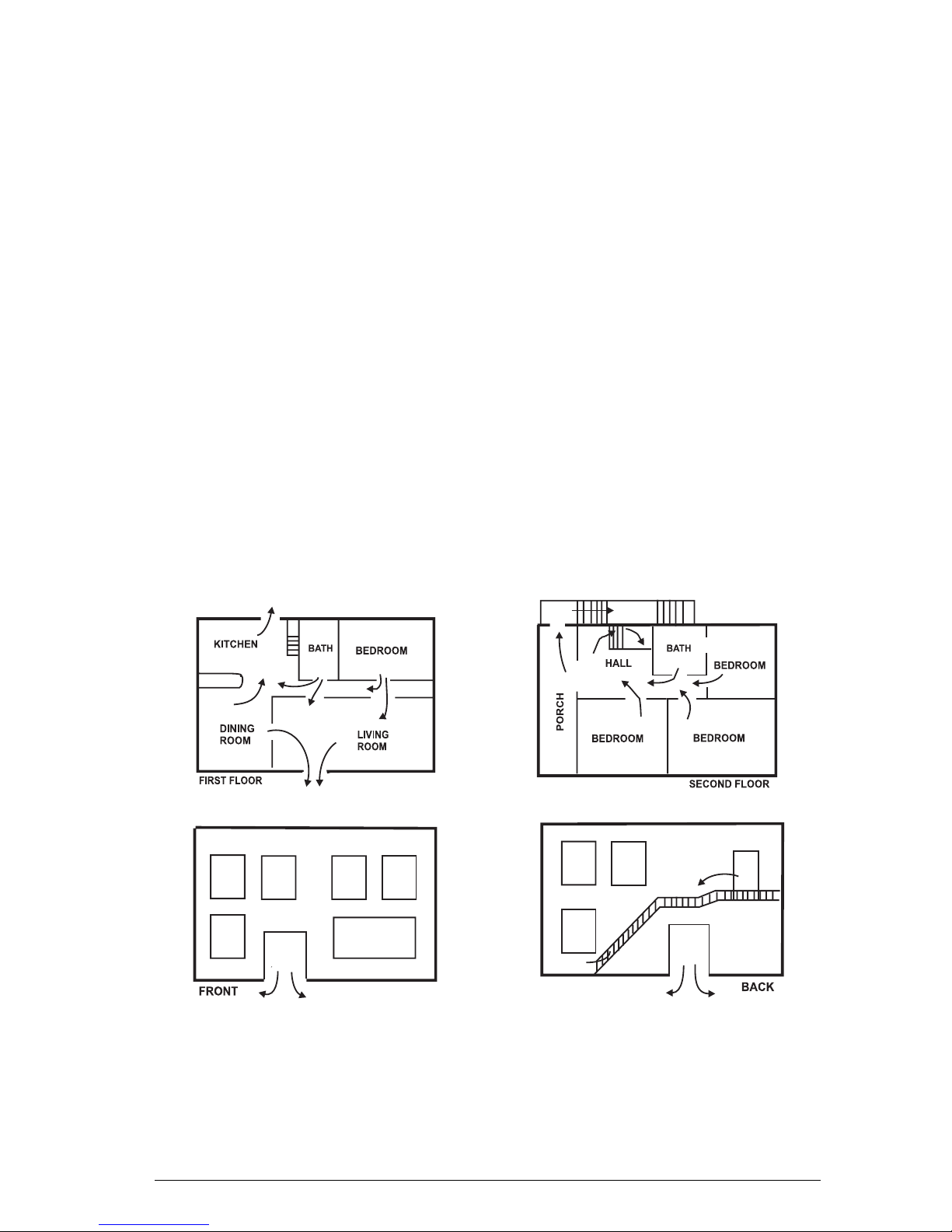
An emergency evacuation plan should be established for an actual fire alarm
condition. For example, the following steps are recommended by the National Fire
Protection Association and can be used as a guid e in establishing an evacuation
plan for your building.
Draw up a floor plan of your home. Show windows, doors, stairs, and rooftops that
can be used for escape. Indicate each occupant's escape r outes. Always keep
these routes free from obstruction. Determine two means of escape from each
room. One will be the normal exit from the building. The other may be a window
that opens easily. An escape ladder may have to be loc ated near the windo w if
there is a long drop to the ground below. Set a meeting place outdoors for a
headcount of the building occupants. Pr actice escape procedures. In a home,
sleep with bedroom door closed; this will increase your escape time. If you suspe ct
fire, test the door for heat. If you think it is safe, brace your shoulder against the
door and open it cautiously. Be ready to sla m the door if s moke or heat r ush in.
Practice escaping to the outdoors and meeting in an assigne d spot. Call th e F ire
Department from a neighbor's phone.
NOTE: After the installation of your Security S ystem has bee n com plet ed, notify
your local Fire and Police Departments to give them your name and address for
their records. Early warning fire detection is best achieved by the installation of fire
detection equipment in all rooms.
Hills LCD Keypad User Manual 2006-12-01
Hills LCD Keypad
25
Page 28
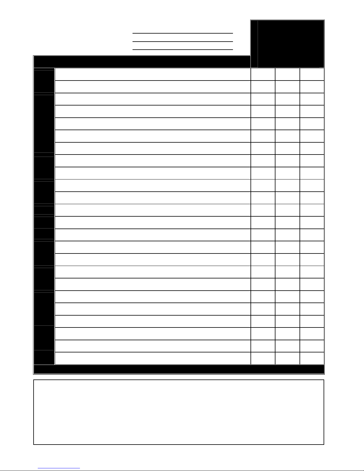
Programmed Phone Number 1:
Programmed Phone Number 2:
Programmed Phone Number 3:
ZONE LIST
ENTRY /
EXIT 24 STAY MODE
24 HOUR
1
2
3
4
5
6
7
8
9
10
11
12
13
14
15
16
17
18
19
20
21
22
23
24
For Service Contact
 Loading...