

Hills Rotary Clothesline 37, Rotary Clothesline 47 Product Manual

Rotary
Clothesline
37 and 47
Product Manual
Everyday
2
Introduction
Please retain this Product Manual. Record the following
information for future reference.
Product Number (printed on carton):
Date of purchase:
Name and location of store:
Made in China
®
Congratulations
Congratulations on the purchase of your Hills
Rotary Clothesline, which will bring you many
years of trouble free and ecient drying.
It’s important that you read this Product
Manual thoroughly before installation to
benefit from the design features and enjoy safe
use of this product.
Thank you for choosing Hills.
Patents and Registered Designs apply to
this product.
Warning
• Do not allow children or pets to swing on
the clothesline or items of laundry.
• Ensure when raising and lowering your
clothesline that bystanders (in particular
children) are standing well clear.
• Do not use for any purpose other than to
hang and dry washing.
• Do not use your clothesline if parts are worn
or damaged.
• Do not allow the frame to lower in an
uncontrolled manner as damage
or injury may result.
Carton Contents
Part name Qty.
Main standard 1
Head assembly 1
Ground socket with cover 1
Plastic spacers 3
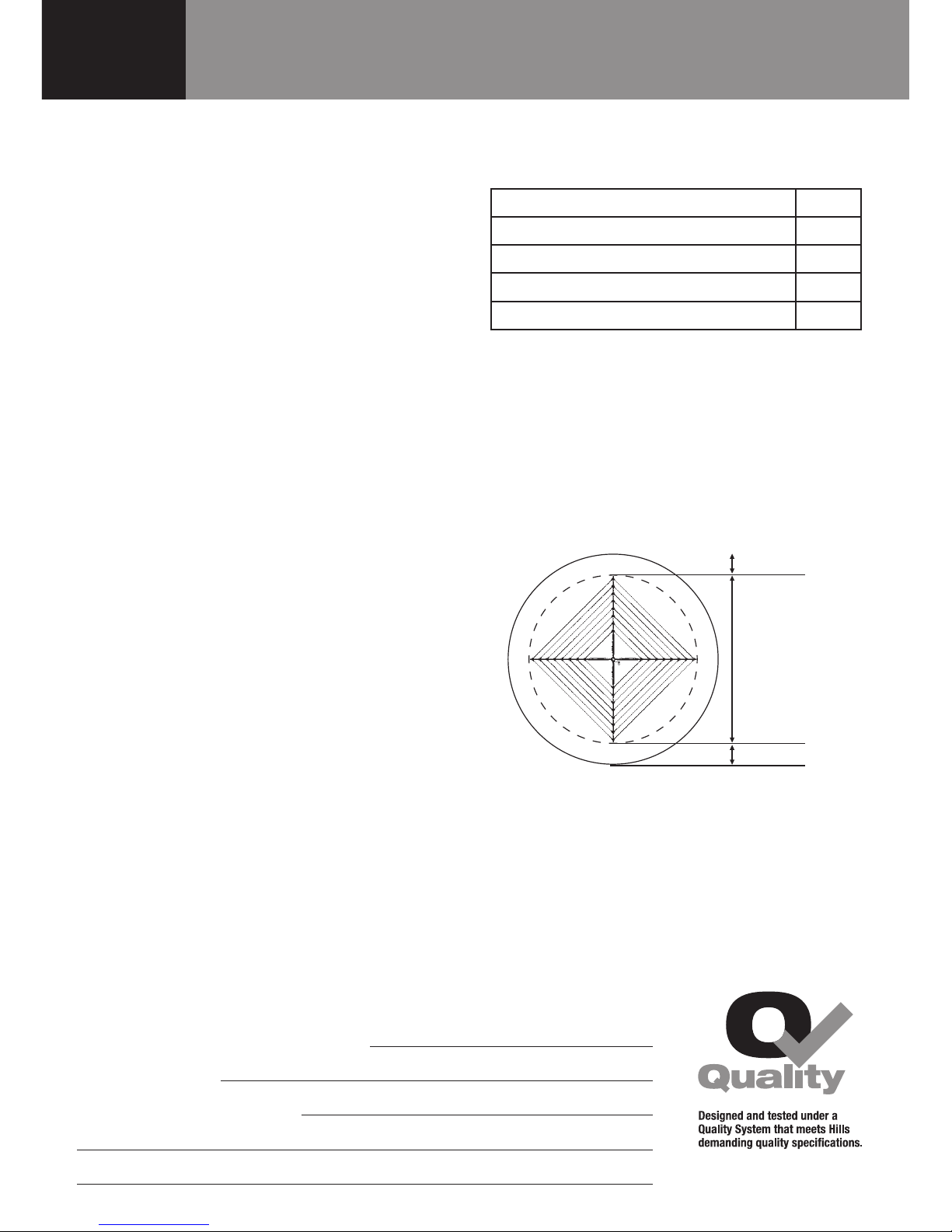
Step 1 – Select a suitable location
1.1 Select a suitable area for installation.
1.2 Allow a minimum of 500mm (1'7")
clearance around your Rotary Hoist (Fig. 1).
Fig. 1
500mm (1'7")
500mm (1'7")
3.2m (10'6")
Rotary 37
3.6m (11' 9")
Rotary 47
3
Installation
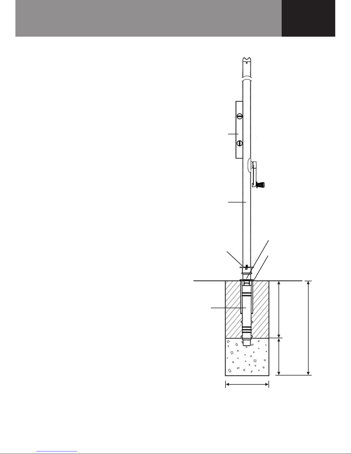
Step 2 – Install the Ground Socket
2.1 Dig a hole 250mm (10") diameter by
approximately 650mm (26") deep (Fig. 2).
2.2
Place approximately 200mm (8") of coarse
gravel into the hole.
2.3
Insert the main standard into the ground
socket. Engage the locking collar and lock
into position.
Make sure the tabs are closed to prevent
concrete entering the locking recess.
2.4
Place the ground socket and main standard
into the hole.
Push the base of the ground socket into
the gravel.
Check level vertically.
The top of the ground socket must sit
approximately 6-12mm (1/4"-1/2") above
ground level.
2.5
Support the main standard and concrete
into position.
Concrete should be damp enough to ‘hold
together’ when squeezed in your hand.
Settle concrete by pushing a thin stick into
the mix several times.
Leave the main standard in the ground
socket until the concrete has set.
Keep concrete out of the locking recess in
the ground socket.
2.6
Allow 24 hours for the concrete to set before
final assembly and use of your Rotary Hoist.
Check for level
Main standard
Locking collar
Engage into
ground socket.
Rotate to lock.
Close tabs to
prevent entry
of concrete
Ground
socket
450mm (18")
concrete
200mm (8")
gravel
650mm (26")
Fig. 2
Top of socket
approximately
6-12mm (1/4"-1/2")
above ground level
250mm (10")
4
Assembly
GENERAL ASSEMBLY DETAILS
ALL DIMENSIONS ARE EQUAL ABOUT UNLESS 1.
OTHERWISE STATED.
DIMENSIONS BOUNDED BY ARE CRITICAL FOR 2.
ASSEMBLY WITH OTHER COMPONENTS.
THE DIMENSIONS SHOWN ON THIS DRAWING PLUS 3.
THE 3D CAD DATA FULLY DEFINE THE FINISHED PART.
ALL COMPONENTS TO BE CLEAN AND FREE FROM 4.
SHARP EDGES, BURRS AND DEFECTS.
IF IN DOUBT ASK5.
GENERAL TOLERANCES:
Unless Otherwise Stated:
0 Dec. place 0.5mm
1 Dec. place 0.25mm
2 Dec. place 0.10mm
Holes: +0.25mm -0mm
Angles: 0.25
6
54321 211101987
1950432 (mm³)
Estimated Mass:
X. Xxxxxxxx
DO NOT SCALE DRAWING.
Projection.
:etaD:devorppA
Date:
XX.XX.XX
Checked:
24.09.10
P. Stevens
Date:
Drawn:
TM
Material:
Finish:
DIMENSIONS IN MILLIMETRES.
Third Angle
REFER TO INDIVIDUAL COMPONENTS
9187 (grams)
REFER TO DRAWING SPECIFICATION
Volume
Hills Industries Limited
ABN 35 007 573 417
Home & Hardware Products
Unit H, 5 Butler Boulevard
Burbridge Business Park
Adelaide Airport
South Australia 5950
Copyright
©
Additives:
ISSUEREF.REV ISIONDATERFC DWN. CHK. APP.
1 SP01.90.42KROWTRA ROF DESAELER
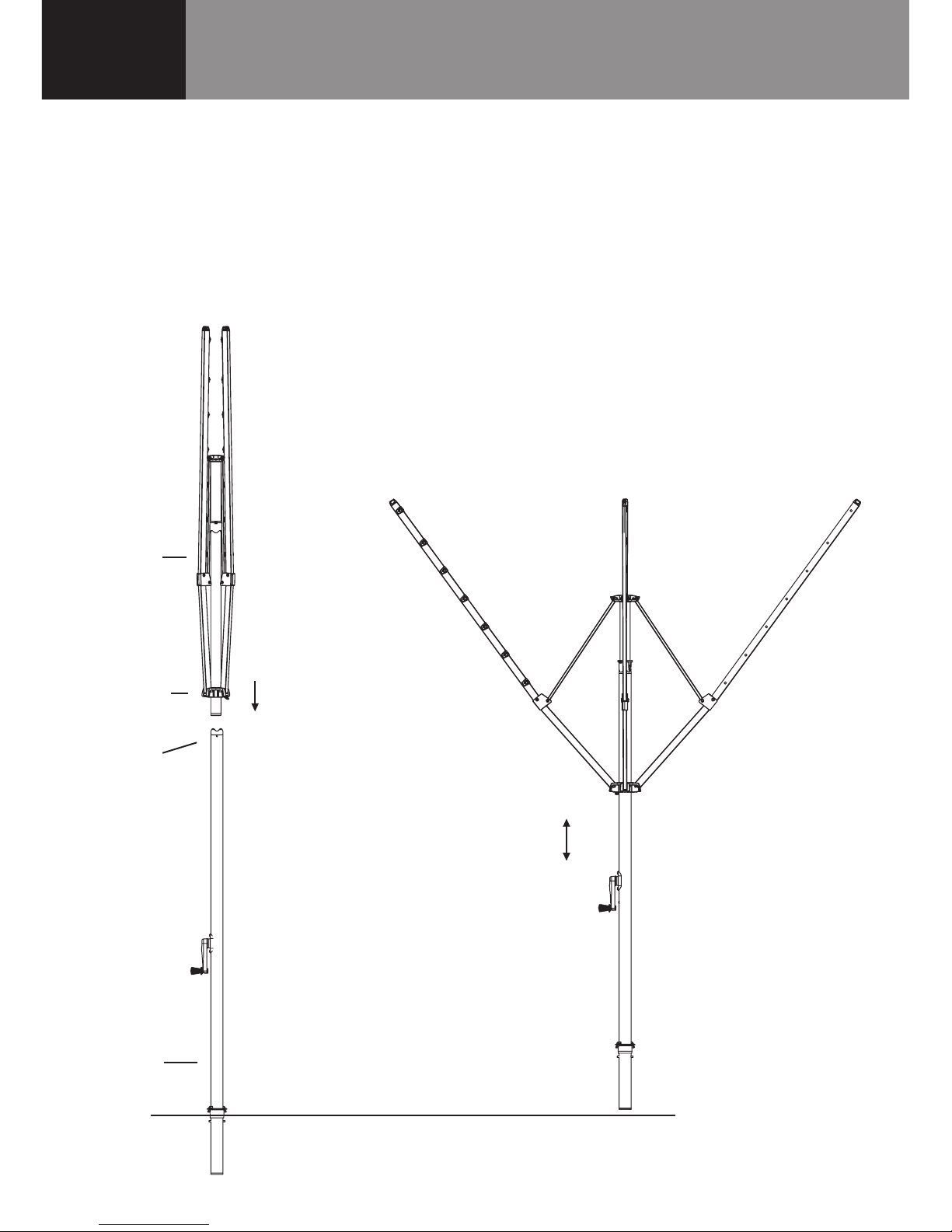
Step 3 – Assemble the Hoist
3.1 Place the main standard in the
ground socket.
3.2
Place the bottom of the head assembly
into the top of the main standard and
lower it gently until it stops (Fig. 3).
3.3
To engage, raise the head assembly by
approximately 100mm (4") and lower until
a ‘click’ is heard.
3.4
Check the head assembly is locked in
position by lifting upwards (it should
not move). If the head assembly is not
engaged, repeat Step 3.3.
Note: There is a small amount of rotational
movement between the wind brake and
the lower cross latch.
This is normal.
Note: Once the head is engaged into the
main standard it cannot be removed.
GENERAL ASSEMBLY DETAILS
ALL DIMENSIONS ARE EQUAL ABOUT
C
L
UNLESS
1.
OTHERWISE STATED.
DIMENSIONS BOUNDED BY ARE CRITICAL FOR
2.
ASSEMBLY WITH OTHER COMPONENTS.
THE DIMENSIONS SHOWN ON THIS DRAWING PLUS
3.
THE 3D CAD DATA FULLY DEFINE THE FINISHED PART.
6
E
A
B
C
D
5
7
8
9
10
11
12
GENERAL ASSEMBLY DETAILS
ALL DIMENSIONS ARE EQUAL ABOUT
C
L
UNLESS
1.
OTHERWISE STATED.
DIMENSIONS BOUNDED BY ARE CRITICAL FOR
2.
ASSEMBLY WITH OTHER COMPONENTS.
THE DIMENSIONS SHOWN ON THIS DRAWING PLUS
3.
THE 3D CAD DATA FULLY DEFINE THE FINISHED PART.
ALL COMPONENTS TO BE CLEAN AND FREE FROM
4.
SHARP EDGES, BURRS AND DEFECTS.
IF IN DOUBT ASK
5.
GENERAL TOLERANCES:
Unless Otherwise Stated:
0 Dec. place
0.5mm
1 Dec. place
0.25mm
2 Dec. place
0.10mm
Holes: +0.25mm -0mm
Angles:
0.25
6
E
A
B
C
D
F
7
8
9
10
11
12
G
Project:
X. Xxxxxxxx
DO NOT SCALE DRAWING.
DIMENSIONS IN MILLIMETRES.
Third Angle
Projection.
Approved:
Date:
Date:
XX.XX.XX
Checked:
22.09.10
P. Stevens
Date:
Drawn:
TM
Colour:
Material:
Finish:
Estimated Mass:
REFER TO INDIVIDUAL COMPONENTS
9534 (grams)
REFER TO DRAWING SPECIFICATION
REFER TO COLOUR TABLE
Volume
2215249 (mm³)
Hills Industries Limited
ABN 35 007 573 417
Home & Hardware Products
Unit H, 5 Butler Boulevard
Burbridge Business Park
Adelaide Airport
South Australia 5950
Copyright
©
2010
Additives:
Insert head
assembly
Main
standard
Head
assembly
Ground level
Lower
cross
Wind
brake
Engage by
raising and
lowering head
assembly until a
‘click’ is heard
Fig. 3
 Loading...