

Page 1

Reliance
TM
8, 12, 128 Zone Control Panel
Installation & Programming Manual
(Australian and New Zealand Version)
Page 2
Hills Reliance Control Panel
Thank-you for choosing the Hills Reliance Control Panel!
The Hills Reliance security control panel from Hills Industries represents a new approach to security system design.
Drawing on experience from the world market, Hills has develo ped the most flexible, dur able, and user-friend ly control ever
seen in our industry. Featuring sophisticated software that allo ws up to 9 9 users to i nterface with 128 z ones, 8 areas, and a
host of integrated fire, access, verification, and input/output modules, all reported with the Contact I.D. formats. The
modular design establishes a logical solution for ease of expansion. Up to 32 modules can be added to expand the
capabilities of the Hills Reliance.
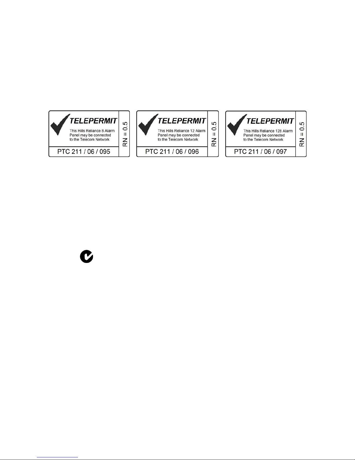
NZ Telepermit Notice
Warnings
The equipment should be installed by
qualified SERVICE PERSONNEL only
The equipment should only be operated with
an approved power adapter with insulated live pins
CAUTION – RISK OF EXPLOSION IF BATTERY IS REPLACED BY AN INCORRECT
TYPE. DISPOSE OF BATTERIES ACCORDING TO THE INSTRUCTIONS.
CONTACT YOUR INSTALLER FOR REPLACEMENT BATTERIES.
When installed as directed, this product conforms to the standards set by
Standards Australia on behalf of the Australian Communications Authority (ACA)
N4131
Disclaimer
The content of this document has been prepared to the best of our knowledge, provided “as is” and is subject to change
without notice. Hills Industries does not guarantee technical accuracy beyond the date of publishing. For the latest
information please enquire about attending one of our Hills Reliance training courses.
Copyright Notice
This work is copyright Hills Industries 2006. Apart from any use as permitted under the Copyright Act 1968, no part may be
reproduced by any process, including photocopying, scanni ng or other means, without prior written permission from Hills
Industries. Creation of derivative work unless agreed to in writing by the copyright owner is forbidden.
Page 3

© Hills Industries 2006 Page 1
Hills Reliance Control Panel
Installation Manual
Page
Warnings...............................................................................................................................................................................1
Compliance Notices.............................................................................................................................................................2
Updated Features.................................................................................................................................................................3
Ordering Information............................................................................................................................................................4
Installation & Programming Flowchart...............................................................................................................................5
Board Installation.................................................................................................................................................................6
Control Panel Comparison..................................................................................................................................................6
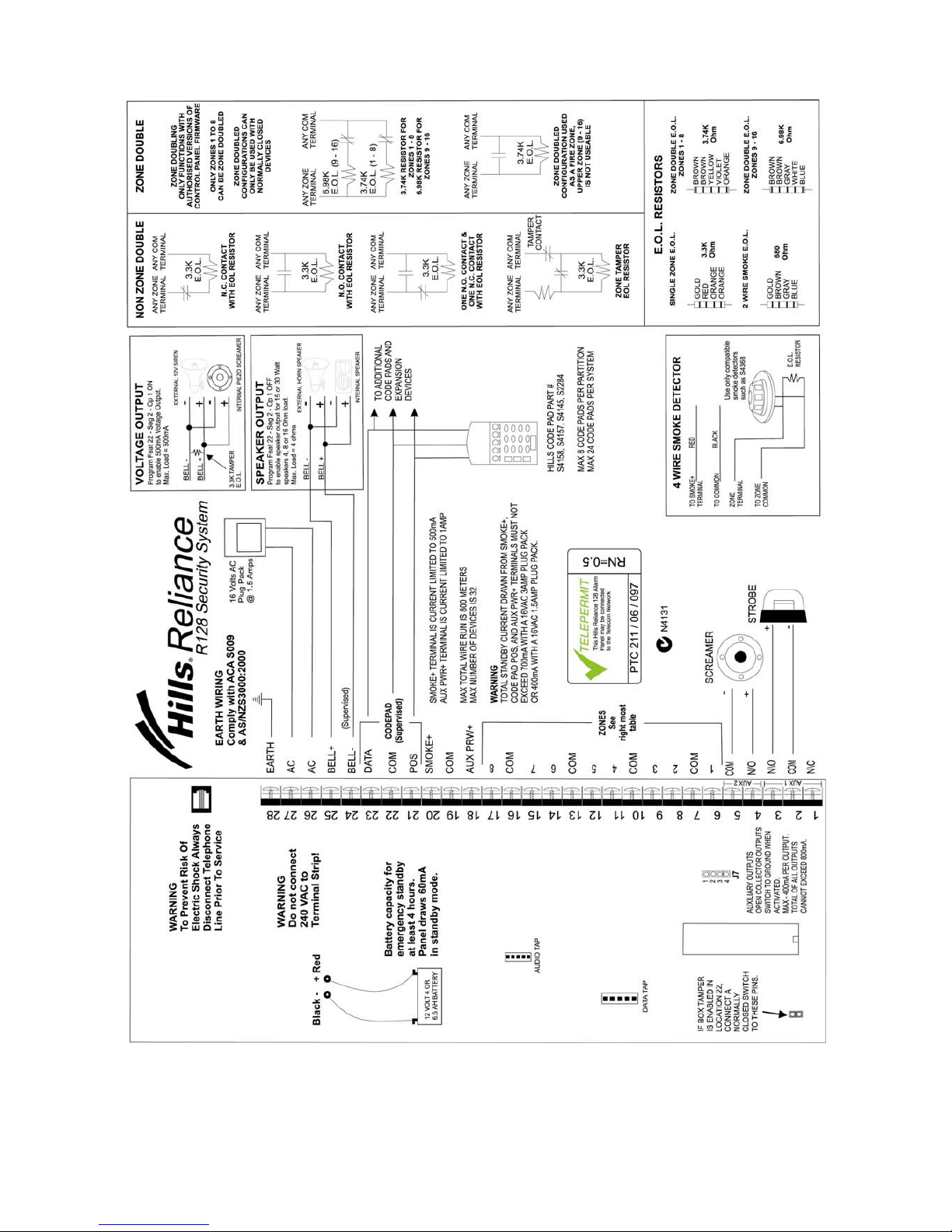
Hills Reliance 128 Wiring Diagram......................................................................................................................................7
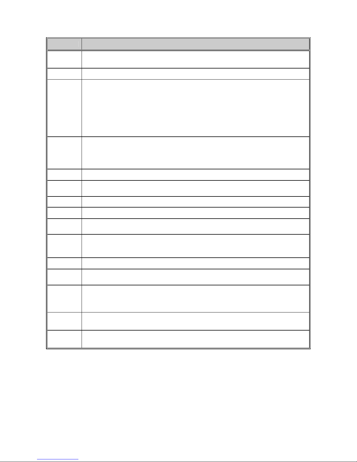
Hills Reliance 128 Terminal Descriptions...........................................................................................................................8
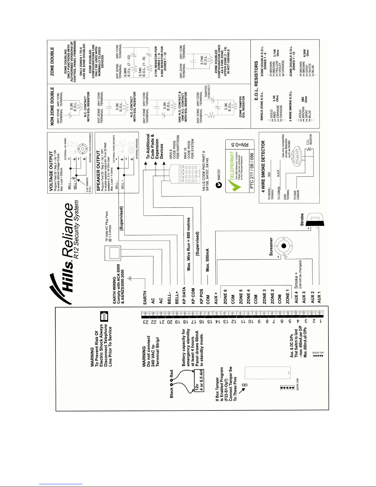
Hills Reliance 12 Wiring Diagram........................................................................................................................................9
Hills Reliance 12 Terminal Descriptions...........................................................................................................................10
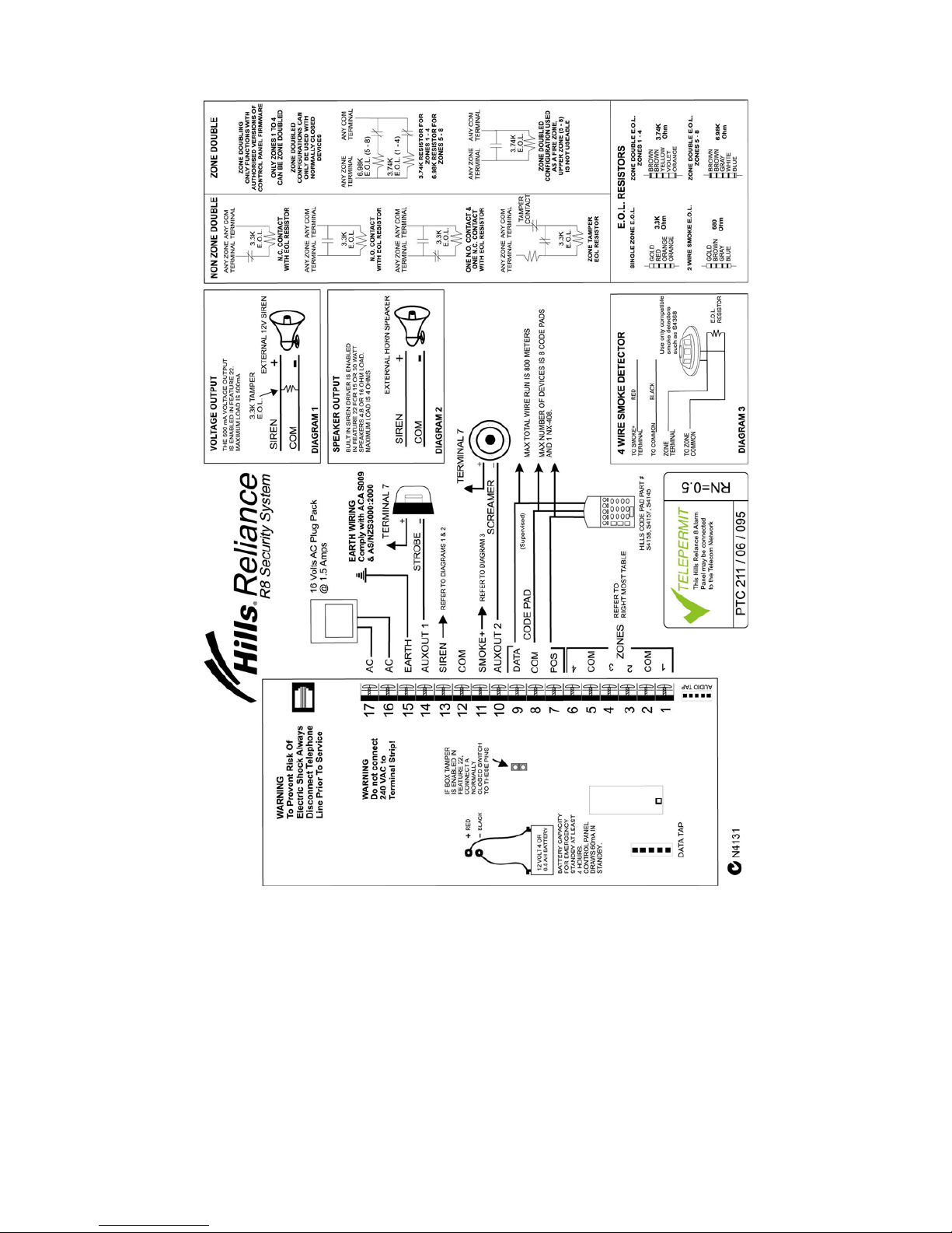
Hills Reliance 8 Wiring Diagram........................................................................................................................................11
Hills Reliance 8 Terminal Descriptions.............................................................................................................................12
Main Options.......................................................................................................................................................................13
Programming The LED Code Pads...................................................................................................................................15
1. Setting The LED Code Pad Starting Zone - Function [9] [2]...............................................................................15
2. Setting The LED Code Pad Options - Function [9] [3]........................................................................................15
3. Setting The LED Code Pad Number And Area Options - Function [9] [4] ..........................................................16
4. Set Elapsed Hours Since Last Auto Test - Function [9] [5] ................................................................................16
5. Set System Date - Function [9] [6] .....................................................................................................................16
6. Setting The System Clock - Function [9] [7].......................................................................................................16
7. Service Menu - Function [2] ...............................................................................................................................17
8. Changing User Codes - Function [5]..................................................................................................................17
9. Assigning User Code Authority Levels - Function [6].........................................................................................18
10. Walk Test Mode - Function [Á] [Chime]...........................................................................................................19
11. Call Back Download [Á] [9] [8] and Answer Call [Á] [9] [9]..............................................................................19
Programming The Hills Reliance Control Panel ..............................................................................................................20
Features, Segments and Options...........................................................................................................................20
Navigating Program Mode .....................................................................................................................................20
Programming Data.................................................................................................................................................21
Loading Factory Defaults .......................................................................................................................................21
Enrolling Modules & Code Pads.............................................................................................................................21
Programming Example Figure1 - Numerical Data (Binary)....................................................................................22
Programming Example Figure 2 - Option Selection Data.......................................................................................22
Programming Feature Descriptions..................................................................................................................................23
System Codes........................................................................................................................................................23
Dialer Options (Features 4 – 11)............................................................................................................................24
Download Options (Features 12 – 15) ...................................................................................................................26
Area 1 – Option and Report Selections..................................................................................................................27
Zones 1 – 8 Configuration......................................................................................................................................29
Default Zone Configurations ..................................................................................................................................29
Zones 9 – 16 Configuration....................................................................................................................................31
System Options
new
................................................................................................................................................32
Siren / Communicator Attempt Counter .................................................................................................................35
Code Pad Sounder Control....................................................................................................................................35
System Timer Configuration...................................................................................................................................35
Auxiliary Output 1 – 4 Configuration.......................................................................................................................36
Auxiliary Output 1 – 4 Logic
new
..............................................................................................................................37
Auxiliary Output Logic Selection
new
........................................................................................................................38
Auxiliary Output Event Selection............................................................................................................................38
Areas 2 – 8 Programming Options.........................................................................................................................40
Zones 17 – 48 Configuration..................................................................................................................................44
Configuration Groups 1 – 20..................................................................................................................................45
Zones 49 – 128 Configuration
new
...........................................................................................................................51
Appendix 1: Reporting Zone Codes in Contact I.D..........................................................................................................55
Appendix 2: Reporting Fixed Codes in Contact I.D.........................................................................................................56
Appendix 3: Expander Numbers for Reporting Expander Trouble................................................................................57
Appendix 4: Troubleshooting System Problems.............................................................................................................59
Installation Floor Plan........................................................................................................................................................62
Program Planning Sheets..................................................................................................................................................63
Page 4

© Hills Industries 2006 Page 2
Compliance Notices
Information to the Installer - Changes and modifications not expressly approved by Hill s can void the user’s authority to
operate the equipment.
Australia & New Zealand Compliances
This equipment has been tested and found to compli ant with the ACA A-T ick and (NZ) T elepermit standards. T hese limits
are designed to provide reasonable protection against interference in a re sidential installation.
Hills Reliance systems fitted with the 433 MHz wireless receiver module receives radio frequency energ y from wireless
transmitters and, if not installed and used in accordance with the instructions, may cause harmful interference to radi o
communications. However, there is no guarantee that interference will not occur in a particular installation. If this
equipment does cause harmful interference to radio or television reception, which can be determined by turning the
equipment off and on, the user is encouraged to try to correct the interference by one or more of the following measures:
• Reorient or relocate the wireless transmitter units or receiver module to reduce interference.
• Increase the separation between the transmitting units and receiver.
• Connect the affected equipment and the panel receiver to separate power outlets, on different branch circuits.
• Consult the dealer or an experienced radio/TV technician for help.
A 230-240VAC mains power outlet (GPO) with protective earthing connection must be provided within reach of the
supplied plug pack power lead and be easily accessible. Only licensed electrical workers should install n ew GPOs. GPO
installation must comply with AS/NZS 3000:2000 and national or state electrical regulations. Co nnect this product to a
compliant 611, Mode3 or switched 8P4C socket. A RJ1 1p ho ne lead is required to connect this product to a compliant 611,
Mode3 or switched 8P4C socket. A compliant RJ11 lead is supplied with this product.
Alarm dialing equipment must be able to seize the telephone line a nd place a call in an emergency situation. It must be
able to do this even if other equipment (te lephone, answering system, computer m odem, etc.) already has the telep hone
line in use. To do so, alarm dialing equipment must be connected t o a ACA (Aust.) or Telepermit (NZ) compliant Mode -3
socket that is electrically in series and ahead of all other telecommunication equipment attached to the same telephone
line. In Australia, only ACA certified technicians are permitted to install or modify telephone sockets.
Security Installation License
Australia installers - In New South Wales and the ACT the installer m ust hold a Security Installer License to install this
product.
New Zealand - All people involved in the s elling, installation and servicing of security equipment must hold a Securit y
Guards Licence. Refer to the NZ Government Justice Department for further updates.
Note: Other national/state regulations may also apply. Enquire at the p lace of purchase if specific installation regulation s
demand the Hills Reliance control panel installation requires a licensed installation technician.
Automatic Dialing Devices (Australia and New Zealand)
This equipment shall not be set to make automatic calls to the ‘000’ (Aust) or the Telecom ‘111’ (NZ) Emergency Service.
Series Connected Equipment (Australia & New Zealand)
The equipment may be set up to carry out test calls at pre-determined times. Such test c alls will interrupt any other calls
that may be set up on the line at the same time. The timing set for such test calls should be discussed with the installer.
The timing set for such test calls from this equipment may be subject to “drift”. If this proves to be inconvenient and your
calls are interrupted, then the problem of timing should be discussed with the equipm ent installer. T he matter should NOT
be reported as a fault to your telephone service provider faults service.
Automatic Re-attempts to the Same Number (New Zealand only)
Some parameters required for compliance with Telecom’s Telepermit requirements are dependent on the equipment
associated with this device. The associated equipment shall be set to operate within the following limits for compliance
with Telecom’s specification:
(a) There shall be no more than 10 call attempts to the same number within any 30 minute period for any single
manual call initiation.
(b) The equipment shall go on-hook for a period of not less than 30 seconds between the end of one attempt and the
beginning of the next attempt.
Automatic Call to Different Numbers (New Zealand only)
Some parameters required for compliance with Telecom’s Telepermit requirements are dependent on the equipment
associated with this device. In order to operate within the limits for compliance with Telecom Specifications, the
associated equipment shall be set to ensure that automatic calls to different numbers are spaced such that there is no
less than 5 seconds between the end of one attempt and the beginning of another.
Fault Clearance (New Zealand only)
In the event of any problem with this device, the telephone lead should be disconnect ed from the LINE connection at the
rear of the unit. The user is then to arrange with the supplier of the dev ice to make necessary repairs. Shou ld the matter
be reported to Telecom as a wiring fault and the fault is proven to this device, a call-out charge will be incurred.
Page 5

© Hills Industries 2006 Page 3
Updated Features
There are new features on the Hills Reliance product, and some which have been changed
from the previous version.
These have the text “
new
” next to the relevant sections in this manual. A summary of key updates is presented below.
Feature
Location
Description
Feature
Location
Description
F5, 37, 38,
41, 44, 47,
50, 53, 56
Account Codes – expanded for future use F33 Auto Disarm Time – added
F16, 39,
42, 45, 48,
51, 54, 57
Area Options – added Late To Close, Auto
Arm in Partial, Disable Bypass For Force
Arm Zones
F36
Days of the Week for Auto Arm – added
Retry Timer
F17, 40,
43, 46, 49,
52, 55, 58
Entry / Exit Timers – expanded for future use
F22
System Options – added Two Wire Smoke,
Zone Inactivity Monitor, Steady/Evac Siren
F22 Disable hardwire zones req power cycle
F68, 70,
72, 74, 76,
78, 80, 82,
84, 86, 88,
90, 92, 94,
96, 98,
100, 102,
104, 106
Configuration Groups – added Zone
Activity Monitor, EOL Defeat, REX
event, DOTL and Forced Door events
F25
System Timers – added Chime Option, Zone
Inactivity Monitor
F119 - 138 Zones 49-128 – added
F27 Auxiliary Output – changed on Reliance 8 F155
Days of the Week for Auto Disarm –
added
F28 - 31 Auxiliary Output Logic – enhanced F162 EOL Resistor Value Select – added
Sales & Distribution
For Service / Technical Support call
(02) 9717 5222 or 1800 252 213
SA
Edwardstown:(08) 8375 9900
NSW
Granville: (02) 9897 7722
Chatswood: (02) 8467 1467
Rosebery: (02) 9698 9698
VIC
Rowville: (03) 9755 6922
Coburg: (03) 9383 2066
WA
Balcatta: (08) 8240 4420
ACT
Fyshwick: (02) 6280 9630
QLD
Bowen Hills: (07) 3852 5512
Ashmore: (07) 5597 7203
TAS
Hobart: (03) 6234 9455
Auckland
Penrose: (09) 525 8007
Christchurch
Sydenham: (03) 374 6277
Wellington
Lower Hutt: (04) 939 9355
Page 6
© Hills Industries 2006 Page 4
Ordering Information
Hills Reliance System Modules & Equipment
Part # Description DAS Code
NX-8-v2-HILLS Hills Reliance 128 Control Panel S4133
NX-6-v2-HILLS Hills Reliance 12 Control Panel S4142
NX-4-v2-HILLS Hills Reliance 8 Control Panel S4697
NX-1508-HILLS Vertex 8 Zone LED Code Pad S4158
NX-1516-HILLS Vertex 16 Zone LED Code Pad S4157
NX-108-HILLS 8 Zone LED Code Pad S4127
NX-116-HILLS 16 Zone LED Code Pad S4132
NX-124-HILLS 24 Zone LED Code Pad S4131
NX-148-HILLS Alphanumeric LCD Code Pad S1241A
NX-1448-HILLS Icon LCD Code Pad S2284
NX-216E 16 Zone Expander Module S4387
NX-507E 7 Relay Expander Module S4164
NX-508E 8 Output Expander Module S4128
NX-408EI 8 Zone Wireless Expansion Module S4135
NX-416EI 16 Zone Wireless Expansion Module S4134
NX-448EI 48 Zone Wireless Expansion Module S4136
NX-320E Smart Power Supply and Bus Extender S4137
NX-536E DTMF Communicator Module (only for Reliance) S1204A
- DTMF Monitor Module (for commissioning & testing) S3079
NX-583 STU Interface S4143
NX-584E RS232 Serial Interface Automation S4703
NX-586E Direct Connect Lead S4714
NX-588E USB Flash Programming Lead S1221A
NX-590E Ethernet TCP/IP Interface S3159
60-707-43-EUR ITI 2 Button Keyfob Transmitter S5735
60-659-43-EUR ITI 4 Button Keyfob Transmitter S5753
60-705-43-ENG ITI Pendant Panic Transmitter S5744
DL900 NX/Hills Reliance Downloader Software -
NX-1701E Proximity Card Reader S1845
NX-002 Metal Box Small (for Hills Reliance 8) S4146
NX-003 Metal Box Large (for Hills Reliance 12 and 128) S4700
Page 7
© Hills Industries 2006 Page 5
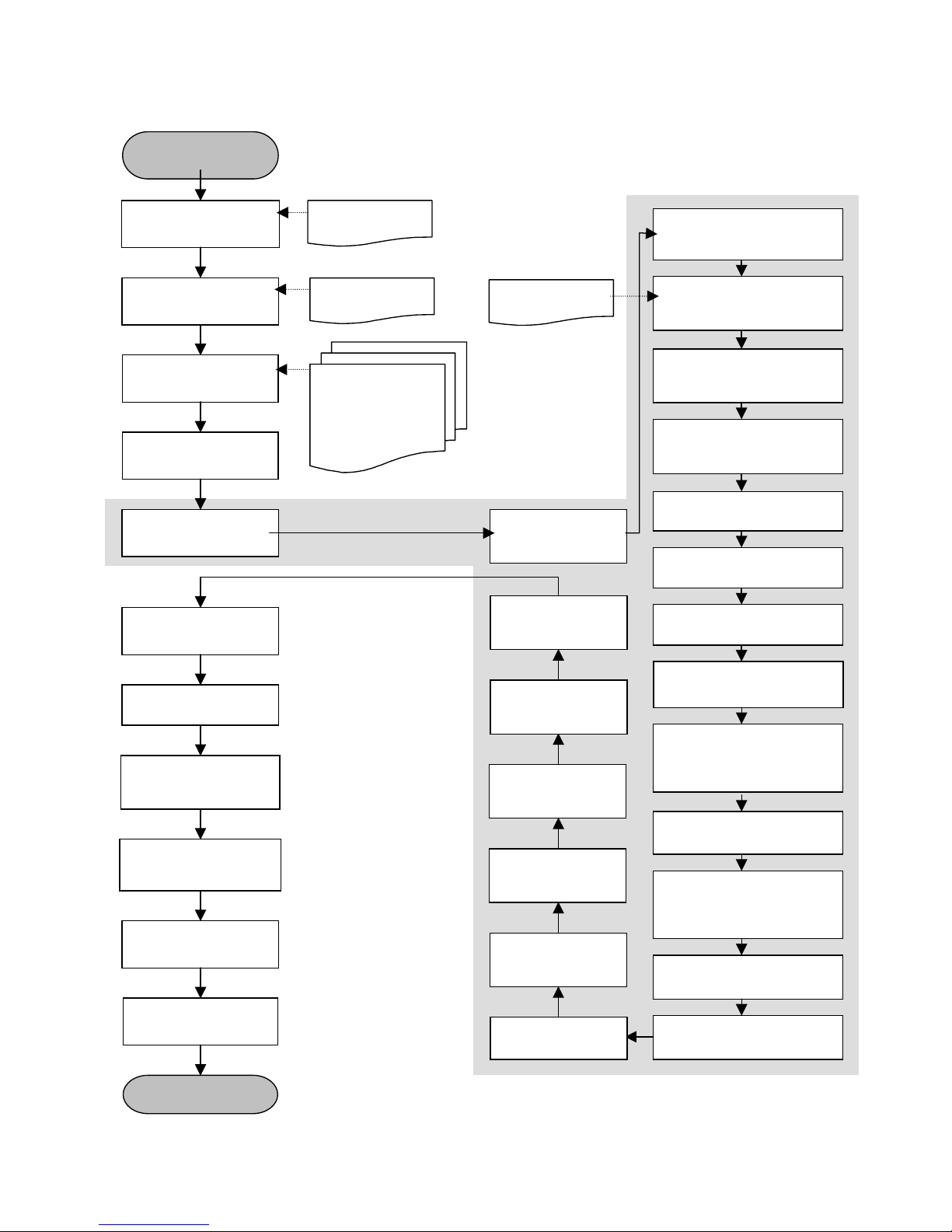
Note –This diagram is a guide for basic system programming only.
Configuration depends upon customer requirements
Installation & Programming Flowchart
Program Phone 1 (4#)
Account code (5#)
Report Format (6#) p 24
Program Event Reports (9#)
& No. Dial Attempts (10#)
p 25
Set Phone Line Cut
Delay (11#) p 25
Program Area 1 Options (16#)
& Entry/Exit Time (17#) p 27
Change Installer Code (1#) &
Duress Code (3#)
p
23
Program Zones 1-8 (18#)
& Area allocation (19#) p 29
Default System
Programming
p 21
Customer
User Details p 63
via code pad (or DL900 software)
Program System Options
(22#) p 32
For Multiple Area Systems
see F37-58 p 40-44
Program Phone 2 (7#)
& Phone 3 (8#)
if required p 25
Program Zones 9-16
(20#, 21#) p 31
Zones 17-48
(59# - 66#) p 44 -45
Program Siren/
Communication Attempts
(23#) & Code Pad Sound
Options (24#) p 35
Program System Timers (25#)
p 35
Program Autotest Time &
Freq. (32#) p 39
Plan & quote
installation p 62
Order modules and
hardware p 4
Install cabling
p 7
Mount equipment
Program system
p 20
Customer
Re
q
uirements
Train customer to use
system
Test user codes
Walk test sensors
(¹ Chime) p 19
Test timers
(siren, entry, exit, etc)
(¹44)
Test phone numbers
(Cent Stn. & mobiles)
(
¹44)
Test battery back up
(¹44)
System Handover
Planning Sheet
see p 63
DAS order form/s
ACA Cab ler
Electrical Contractor
Security License
(NSW)
or other local
re
q
uirements
Program System
Date (¹96)
p 16
Program Code Pad
No. & Areas (¹94)
p 16
Program Code Pad
Options (¹93)
p 15
Program System
Time (¹97)
p 16
Exit Program Mode
p 20
Program User
Codes (¹5)
p 17
Page 8
© Hills Industries 2006 Page 6
Board Installation
The metal enclosure should be installed with the door opening from the top to bottom. It
should be installed away from damp areas (e.g. bathrooms, kitchens), away from sources of
heat, dust or interference (e.g. air conditioners, washing machines, dryers, refrigerators) and
away from external walls.
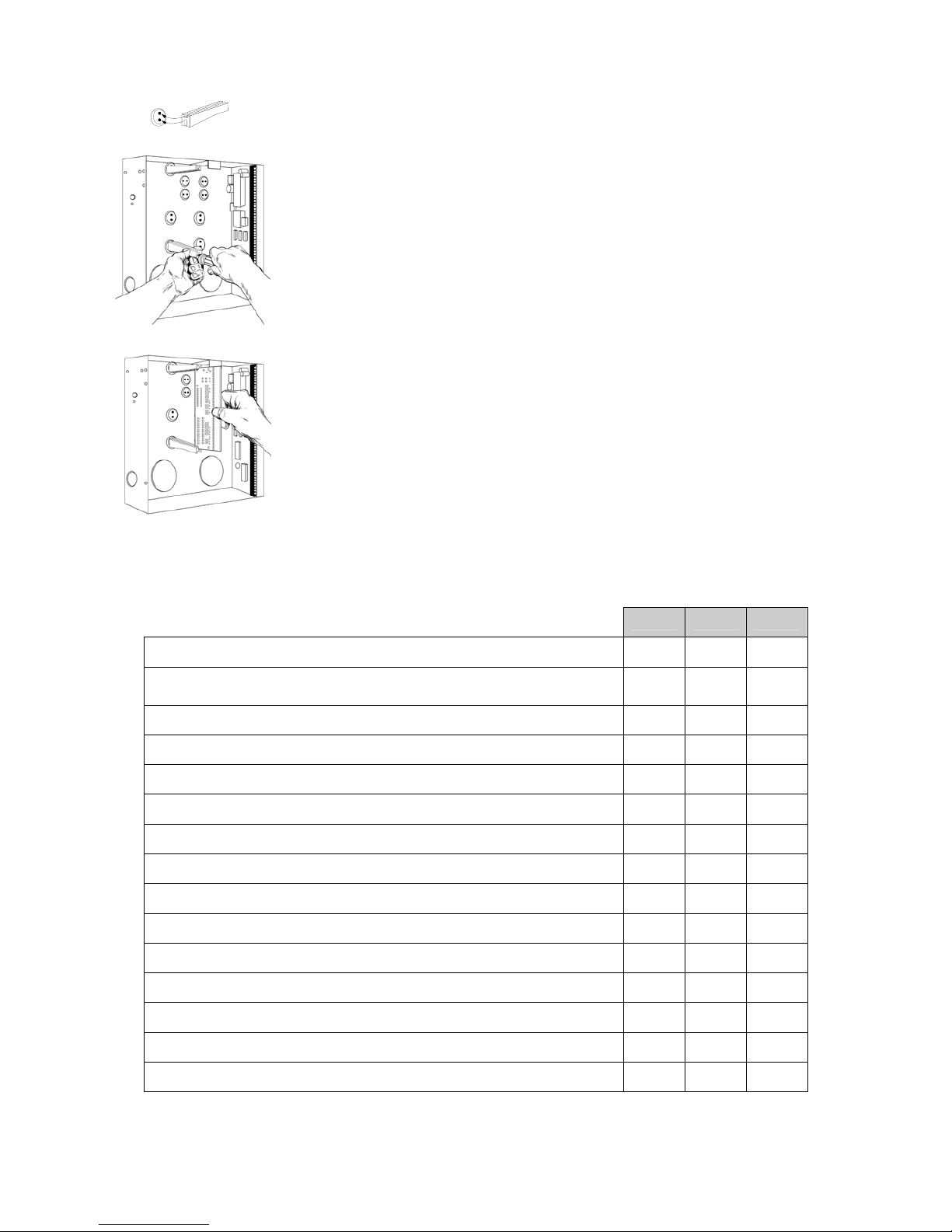
Inside the enclosure there are four slots for board inserti on, two on the top and two on the
bottom of the enclosure. These allow the PC board to be positioned vertically as shown in the
diagram. When you slide the board between the grooves of the slots, make sure the terminal
strip is toward the front opening (toward you) to allow for the wire connections.
Inside the enclosure several 2-holed insertion points have been construc ted. This allows for
either vertical or horizontal placement of the modules. Notice that each insertion point has
two sizes of holes - a larger hole and a smaller hole.
Diagram 1: The black plastic PCB guides are grooved on one edge where the PC board will
be seated. The end with the half-moon protrusion fits into the larger hole. T he smaller hole is
for the screw.
Diagram 2: Place the first black plastic PCB guide in the top insertion point, grooved edge
downward. The half-moon protrusion will be in the large hole. It does not require force to
insert. Insert one of the provided screw into the smaller hole (from inside the enclosure) to
secure it in place. A screwdriver should reach through the notch that run s the length of the
guide to tighten the screw. The second PBC guide should be positioned opposite the first
(grooved edge up) and placed in the lower insertion point, using the same procedures
described above. Once mounted, screw it in securely.
Diagram 3: The PC Board should slide freely in the grooves of both guides.
Control Panel Comparison
R8 R12 R128
Independent number of zones 8 12 16
Expandable to a maximum number of zones
(a combination of hardwired and/or wireless)
8 16 128
Anti-tamper supervision of all zones (hardwired and wireless) Yes Yes Yes
Full supervision of all expansion module and codepads Yes Yes Yes
Individual areas/partitions 1 2 8
Total number of user PIN codes (4 digit) 8 40 99
Maximum number of codepads 8 16 24
Codepad tampers Yes Yes Yes
Uni Arming (single button arming for full or partial mode) Yes Yes Yes
Home mode/Partial mode arming Yes Yes Yes
Automatic arming (and auto partial mode arming) Yes Yes Yes
Re-exit Yes Yes Yes
Real-time event history (maximum events) 185 185 185
Phone line monitor No Yes Yes
Fire alarm verification Yes Yes Yes
Page 9
© Hills Industries 2006 Page 7
Hills Reliance 128 Wiring Diagram
Page 10
© Hills Industries 2006 Page 8
Hills Reliance 128 Terminal Descriptions
Terminal Description
EARTH
Earth / Ground.
To comply with ACA S009 & AS/NZS3000:2000. Connect to the 16.5V AC plug pack earth wire.
AC
AC input. Connect a 16.5V, 25 VA, 40 VA or 50 VA approved transformer.
BELL + &
BELL -
Built in siren driver, if used as a siren output (default), the speaker rating should be
15 Watt at 8 or 16 Ohm, or 30/40 Watt at 4, 8, or 16 Ohm, 250mA maximum load.
If voltage output is selected in Feature 22 - Segment 2 - Option 1, this output becomes voltage
output, 12 VDC, 1 Amp maximum load.
Note: A 3.3K
Ω
resistor may be required across the bell terminals when a 12 VDC siren is used.
If no resistor is used, you may experience voltage leakage into the siren that will cause thes e devices
to output a small signal.
KP DATA
Connect the to the KP data terminal on the code pads and the expanders (usually blue or green
wire). Maximum total wire run is 800 metres using 14/020 cable. These numb ers are for one code
pad at the end of the wire. When connecting more than one code pad to the system bus wire, a
higher gauge wire will be required, or there will be a re duction in maximum wire distance. Maximum
32 devices.
KP COM
Connect to the Common terminal on the code pads and the expanders (usually the black wire).
KP POS
Connect to the Positive terminal on the code pads and the expanders (usually the red wire).
The KP POS and AUX PWR + terminals are limited to 1 Amp total current when added together.
SMOKE+
Smoke detector power 12VDC, 500mA maximum.
COM
Connect negative wire of powered devices such as motion detectors and smoke detectors.
AUX PWR+
Connect positive wire of all powered devices except smoke detectors and code pads.
This terminal and KP POS are limited to 1 Amp total current when added together.
ZONE 8
Connect to one side of zone 8 loop. Connect the other side to a COM termi nal. Open or short cause s
alarm. Zone 8 may be used f or a two- wire smoke detector using a 680Ω E.O.L. resistor. See Featur e
22.
COM
Common (-) terminal for zones 7 & 8. (See the wiring diagram for examples)
ZONE 7 -
ZONE 1
Connect to one side of zone loop. Connect the other side to a COM terminal. Open or short causes
alarm. Only zone 8 can be a two-wire smoke zone. (See the wiring diagram for examples)
AUX
RELAY
OUT 1-2
Relays one and two switch a 12 volts output on their N/C and N/O terminals. This me ans that you
connect the positive lead of your device to these terminals, and connect the negativ e lead to a COM
terminal. Ensure your device does not exceed the ratings of these relays, max 400 mA per output,
max 800 mA total output.
AUX
OUT 3-4
Auxiliary outputs 3 and 4 (in addition to 1 & 2) are located on a pin header J7, see wiring diagram for
details.
Battery
Leads
Connect black (-) and red (+) leads to a 12VDC sealed lead acid rechargeable battery.
Do not connect to a dry cell battery.
Warning: Total standby current drawn from SMOKE +, KP POS and AUX PWR +, must not exceed
700 mA with 16 VAC 3 Amp Plug Pack or 400 mA with 16 VAC 1.5 Amp Plug Pack.
Page 11
© Hills Industries 2006 Page 9
Hills Reliance 12 Wiring Diagram
Page 12

© Hills Industries 2006 Page 10
Hills Reliance 12 Terminal Descriptions
Terminal Description
EARTH
Earth / Ground.
To comply with ACA S009 & AS/NZS3000:2000. Connect to the 16.5V AC plug pack earth wire.
AC
AC input. Connect a 16.5V, 25 VA, 40 VA or 50 VA approved transformer.
BELL + &
BELL -
Built in siren driver, if used as a siren output (default), the speaker rating should be
15 Watt at 8 or 16 Ohm, or 30/40 Watt at 4, 8, or 16 Ohm, 250mA maximum load.
If voltage output is selected in Feature 22 - Segment 2 - Option 1, this output becomes voltage
output, 12 VDC, 1 Amp maximum load.
Note: A 3.3K
Ω
resistor may be required across the bell terminals when a 12 VDC siren is used.
If no resistor is used, you may experience voltage leakage into the siren that will cause these devices
to output a small signal.
KP DATA
Connect the to the KP data terminal on the code pads and the expanders (usually blue or green
wire). Maximum total wire run is 800 metres using 14/020 cable. These numbers are for one code
pad at the end of the wire. When connecting more than one code pad to the system bus wire, a
higher gauge wire will be required, or there will be a reduction in maximum wire distance. Maximum
16 devices.
KP COM
Connect to the Common terminal on the code pads and the expanders (usually the black wire).
KP POS
Connect to the Positive terminal on the code pads and the expanders (usually the red wire).
The KP POS and AUX PWR + terminals are limited to 1 Amp total current when added together.
COM
Connect negative wire of powered devices such as motion detectors and smoke detectors.
AUX PWR+
Connect positive wire of all powered devices except smoke detectors and code pads.
This terminal and KP POS are limited to 1 Amp total current when added together.
ZONE 6
Connect to one side of zone 6 loop. Connect the other side to a COM terminal. Open or short causes
alarm.
COM
Common (-) terminal for zones 5 & 6. (See the wiring diagram for examples)
ZONE 5 -
ZONE 1
Connect to one side of zone loop. Connect the other side to a COM terminal. Open or short causes
alarm. Only zone 7 can be a two-wire smoke zone. (See the wiring diagram for examples)
AUX
OUT 4
(or Zone 7
/Smoke +)
Aux 4 defaults to 12VDC smoke power for a four-wire smoke detector.
Alternatively this output can be programmed in Feature 22 as Zone 7 two-wire smoke detector. Use a
680Ω E.O.L. resistor with the two-wire smoke detector. Current is limited to 250mA when output is
negative and 250 microamps maximum when output is positive.
Note: The 2-wire smoke loop cannot be enabled if Zone Doubling is used.
AUX
OUT 1-3
Connect negative lead of low current device (e.g. relay, LED [install 1K resistor in series with LED],
etc). Connect positive lead of device to AUX PWR +. Current is limited to 250mA when output is
negative and 250 microamps maximum when output is positive.
Battery
Leads
Connect black (-) and red (+) leads to a 12VDC sealed lead acid rechargeable battery.
Do not connect to a dry cell battery.
Warning: Total standby current drawn from SMOKE +, KP POS and AUX PWR +,
must not exceed 700 mA with 16 VAC 3 Amp Plug Pack or 400 mA with 16 VAC 1.5 Amp Plug Pack.
Page 13
© Hills Industries 2006 Page 11
Hills Reliance 8 Wiring Diagram
Page 14
© Hills Industries 2006 Page 12
Hills Reliance 8 Terminal Descriptions
Terminal Description
AC
AC input. Connect a 16.5V 1.5A approved plug pack.
EARTH
Earth / Ground.
To comply with ACA S009 & AS/NZS3000:2000. Connect to the 16.5V AC plug pack earth wire.
AUX
OUT 1
Auxiliary Output Terminal, normally used to conn ect the n egative lead of the strob e. T he positive lead
of the strobe can be connected to any of the positive terminals e.g. KP POS. Current is limited to
250mA when output is negative and 250 microamps maximum when output is positive.
SIREN
Built in siren driver, if used as a siren output (default), the speaker rating should be
15 Watt at 8 or 16 Ohm, or 30/40 Watt at 4, 8, or 16 Ohm, 250mA maximum load.
If voltage output is selected in Feature 22 - Segment 2 - Option 1, this output becomes voltage
output, 12 VDC, 500mA maximum load.
Note: A 3.3K
Ω
resistor may be required across the bell terminals when a 12 VDC siren is used.
If no resistor is used, you may experience voltage leakage into the siren that will cause thes e devices
to output a small signal.
COM
Common (-) Terminal
SMOKE+
Smoke detector power 12VDC, 100mA maximum.
At default output is 0V, to enable 12V set F27 - Seg 3 - Op 6 (invert output) to off. See Feature 27.
AUX
OUT 2
Auxiliary Output Terminal, normally used to connect the ne gative lead of the screamer. The positive
lead of the screamer can be connected to any of the positive terminals e.g. KP POS. Current is
limited to 250mA when output is negative and 250 microamps maximum when output is positive.
KP DATA
Connect the to the KP data terminal on the code pads and the expanders (usually blue or green
wire). Maximum total wire run is 800 metres using 14/020 cable. These numb ers are for one code
pad at the end of the wire. When connecting more than one code pad to the system bus wire, a
higher gauge wire will be required, or there will be a r eduction in m aximu m wire distanc e. Maximum 8
devices.
KP COM
Connect to the Common terminal on the code pads and the expanders (usually the black wire).
KP POS
Connect to the Positive terminal on the code pads and the expanders (usually the red wire).
The KP POS and AUX PWR + terminals are limited to 1 Amp total current when added together.
COM
Connect negative wire of powered devices such as motion detectors and smoke detectors.
ZONE 4
Connect to one side of zone 4 loop. Connect the other side to a COM termi nal. Open or short cause s
alarm.
COM
Common (-) terminal for zones 5 & 6. (See the wiring diagram for examples)
ZONE 3 -
ZONE 1
Connect to one side of zone loop. Connect the other side to a COM terminal. Open or short causes
alarm.
Battery
Leads
Connect black (-) and red (+) leads to a 12VDC sealed lead acid rechargeable battery.
Do not connect to a dry cell battery.
Warning: Total standby current drawn from SMO KE +, KP POS and AUX PWR +, must not exceed 700 mA with
16 VAC 3 Amp Plug Pack or 400 mA with 16 VAC 1.5 Amp Plug Pack.
Page 15

© Hills Industries 2006 Page 13
Main Options
Areas
The Hills Reliance 128 can have up to a maximum of eight separate systems (areas) with distinct reportin g codes,
user codes, and operating options for each system (see Features 16-21 and 37-58). T he Hills Reliance 12 has up to
two areas, and the Hills Reliance 8 has one area.
Arm / Disarm Codes
The Hills Reliance 128 can have 99 four-digit codes or 66 six-digit codes to arm/disarm the control. All codes must
have the same number of digits. User codes are programmed and vie wed from the code pad functio ns [*] 5 and [*] 6.
The factory default for user 1 is [1]-[2]-[3]-[4] when using a 4-digit code, or [1]-[2]-[3]-[4]-[5]-[6] for a 6-digit code.
This code can then be used to enter the new arm/disarm codes (see Feature 0). The Hills Reliance 12 can have up to
40 users, the Hills Reliance 8 up to 8 users.
Auto Arm in Partial
The Hills Reliance can be armed automatic ally in the partial m ode. T his option can on ly be us ed for area one. If Auto
Arm in Partial is enabled, area one cannot have full mode Auto Arming selected. (See Feature 22)
Automatic Arming
If programmed, the Hills Reliance will Auto Arm at a specified time. At this time, the code pad will beep for 50
seconds before the panel arms. The auto arming proces s can be stopped by a valid code entry. The Auto Arming of
an area can be programmed to be silent. If closing reports are sent, the user cod e will be 97. (See Features 16, an d
33-36)
Auxiliary Outputs
The Hills Reliance 128 has two (2) programmable rela y outputs and two (2) programmable open collector outputs that
can be used to activate a strobe and two internal sirens. (See the terminal description Features 26-29). The Hills
Reliance 12 has 4 programmable open collector outputs, and the Hills Reliance 8 has two.
Auxiliary Power Over Current
The Hills Reliance will illuminate the ‘Service’ LED on th e code pad whenever too much current is drawn from any
device powered by the system. This condition can be reported to the central station. (See Features 9 and 22)
Box Tamper
The Hills Reliance has an input for a normally closed tamper switch (see wiring diagrams on p7, p9, p11). T he Box
Tamper can be programmed to report and/or sound the siren and/or the Code P ad. These terminals can be e nabled
or disabled in programming. (See Features 22 and 23)
Code Pad Start Zone
The Hills Reliance LED Code Pads can be programmed with a starting zone from 1 to 64. The starting zone
programmed into the LED Code Pad via function [*][9][2] will tie the system zone to zone one (1) of the Code Pad.
I.e. If you wish to start displaying zone 25 as the zone on e (1) on a LED Code Pad, pro gram a 25 as the start zone
into the Code Pad that will function in this manner. When system zone 25 is faulted, zone LED one (1) will illuminate
on the programmed Code Pads. Zone bypasses will be tied to the Code Pad LED number; however reporting will
follow the system zone number.
Configuration Group
The Hills Reliance has 20 programmable and 10 fixed zon e configurati on groups (i.e. zo ne types) that determi ne ho w
each zone will function and report. The first 20 groups can be reprogrammed.
Dual End of Line
All Hills Reliance zones can be enabled for tamper monitoring if the Dual End of Line option is enabled. Zone
Doubling cannot be used if the option is enabled. (See Feature 22)
Dynamic Battery Test
The Hills Reliance can be programmed to perform a dynamic battery test to verify the condition of the battery for a
selected duration the first time the panel is armed or disarmed every day. T he Hills Reliance can also be programmed
to perform a missing battery test every 12 seconds. (See Features 22 and 25)
Page 16

© Hills Industries 2006 Page 14
Exit Error
If enabled, the Hills Reliance will send an ‘E xit Err or Rep ort’ if an entr y/e xit zone is fau lted at the inst ant t he e xit del ay
expires. This report will be sent along with the user number that armed the system, if the panel is not disarmed
before the entry delay expires. The alarm report will also be sent. Even if this option is not enabled, the siren will
sound if any entry/exit zone is faulted at the instant the exit delay expires. (See Feature 9 and 16)
Expander Trouble
The Hills Reliance will report expander trouble to the central station if enabled. This condition will illuminate the
‘Service’ LED on the code pad even if not reported. N ote: The code pads are considered ex panders. The number of
the expansion devices reported can be found in Appendix 3. (See also Feature 9 an d 22)
Fire Alarm Verification
When enabled, the Hills Reliance will verify a fire alarm by waiting for a second trip on a smoke detector within a
specified time before creating an alarm (see Feature 25). To interrupt the smoke detector power (when in the
disarmed state) each time the [*] 7 keys are pressed, the corresponding LE D(s) for zones designated as ‘Fire’ must
be on steady for alarm or blinking for trouble. When the ‘Fire Alarm Verification’ o ption is enabled, a smoke detecto r
will be powered down and reset automatically after the first trip, waiting for a second trip within a specified time before
creating an alarm. The communicator will delay for a specified time b efore reporting the alarm, if a valid code is
entered, the report will be aborted, and the smoke alarm ve rification option will be reset if enabled. If no valid code is
entered the alarm report will be reported to the base station. (See Zone Configuration Group Table and Feature 2 5)
Group Bypass
A designated group of zones can be programmed to bypass by pressing [Bypass]-[0]-[0]-[Bypass] prior to arming.
(See Zone Configuration Group Table)
Internal Event Log
Up to 185 events can be stored in memory along with the date and time of the event. These events can later b e
viewed through downloading or the LCD code pad. All reportable events report to the log.
Number of Calls and Rings to Answer
The Hills Reliance can count the number of calls and rings that must be met for automatic download ans wering.
(See Feature 13)
On Board Zone Disable
The zones on the main Hills Reliance control panel can be disabled in order to have a completely wireless alarm
system. (See Feature 22)
Partial Mode
Partial mode allows system owners to arm only designated partial zones (e.g. downstairs, front doors, garage),
bypassing all non-partial zones (e.g. upstairs bedroom). Part ial mode encourages system owners to use their alarm
system more frequently when the premise is occupied. When armed in the ‘Partial’ mode, the openin g of any zones
designated as ‘Partial Mode zone’ will initiate the code p ad sounder and start the Partial Mode entry delay before
creating an alarm. All other zones will function as normal. (See Zon e configuration Group Table and Features 16
and 25)
Siren Supervision
The Hills Reliance has a siren supervision circuit (B ell + and Bell -) that will consta ntly monitor the siren on the Hills
Reliance and can be programmed to report if the wires are cut. (See Feature 22)
Telephone Line Monitor
The Hills Reliance 128 and Hills Reliance 12 have a telephon e line monitor that monitors the voltage and current of
the telephone line to detect a cut phone line. This condition can als o be reported to the central statio n after the line is
restored. Not available on the Hills Reliance 8.
Twin Trip
This option requires two or more trips on a zone or zones programmed as ‘Twin Trip’ within a specified time before
reporting an alarm. During the time between trips, the Hills Reliance can be programmed to sound the code pad
and/or the siren. The Hills Reliance will als o see an al arm ac tivation if any Twin Trip zone that is continuously faulted
for longer than 10 seconds. (See Zone configuration Group Table and Features 22, 24, and 25)
Page 17
© Hills Industries 2006 Page 15
Programming The LED Code Pads
This section describes how to program the address and area of each code p ad as well as the options that are available.
The code pad address allows the panel to monitor and supervise the connected code pads and report code pad
communication faults.
The factory default for the Master code is [1]-[2]-[3]-[4] when using a 4-digit code or [1]-[2]-[3]-[4]-[5]-[6] for a 6-digit code.
The factory default for the ‘Go To Program’ code is [9]-[7]-[1]-[3] for a 4-digit code or [9]-[7]-[1]-[3]-[0]-[0] for a 6-digit code.
1. Setting The LED Code Pad Starting Zone - Function [9] [2]
Step 1
Your system must be in the Disarmed state to program the code pad settings
Step 2 Press the [Á]-[9]-[2] keys
Step 3 Enter the [Program Code]
Step 4
Enter the Starting zone number from 1 to 128.
Note that older code pads only support up to 48 zones (i.e. non “E” versions”). Keep this in mind when
expanding a site by replacing the panel – some code pads may also need replacing. O n sites with >48
zones it is recommended to use an LCD code pad.
Step 5 Press [Á] to save changes and exit this function
2. Setting The LED Code Pad Options - Function [9] [3]
Step 1
Your system must be in the disarmed state to program the code pad settings
Step 2 Press the [Á]-[9]-[3] keys
Step 3
Enter the [Program Code]. The ‘Service’ LED will flash
LEDs 1-8 can now be toggled on/off to enable/disable the functions listed in the table below:
LED Code Pad Option Enabled
1 Enable Code Pad tamper switch
2 Enable Silent Code Pad option
3 Enable Ding Dong sound for Chime – If off, chime will be a single tone.
4
Enable Key-press Silence option (silences the pu lsing code pad sounder for 5
seconds when a key is pressed)
5
Enable Armed Status Suppression (faulted or bypassed zones will n ot display
on code pad when system armed)
6
Enable Panic, Fire, Medical Beep-tone (will sound a short beep to verif y that the
key-press was accepted)
7
Suppresses the ‘Service’ LED (will not allow the ‘Service’ LED to illuminate for
any reason. If there is a system trouble, pressing [Á]-[2] will still show the service
menu.)
8
Enable multi-area viewing (enables temporary viewing of all areas by pressing
[Á]-[1]-[Area Number])
Step 4 After enabling/disabling the desired functions press [r] to save changes and exit this function.
Page 18
© Hills Industries 2006 Page 16
3. Setting The LED Code Pad Number And Area Options - Function [9] [4]
Step 1
Your system must be in the disarmed state to program the code pad settings
Step 2 Press the [Á]-[9]-[4] key
Step 3 Enter the [Program Code] – The ‘Service’ LED will flash
Step 4 Enter the code pad number [1-8]
Step 5 Press [Á] - The ‘Instant’ LED will illuminate steady and the ‘Service’ LED will remain flashing
Step 6 Enter the [Area Number] for the code pad (the code pad will automatically exit this mode at this time)
4. Set Elapsed Hours Since Last Auto Test - Function [9] [5]
Step 1
Your system must be in the disarmed state to program the code pad settings
Step 2 Press the [Á]-[9]-[5] keys
Step 3 Enter the [Program Code] – The ‘Service’ LED will flash
Step 4
Enter [100's digit] - [10's digit] - [1's digit] for the elapsed hours
Example: if you have programmed the Auto-Test intervals to report every 72 hours, the value in this
function will determine the first time the auto test report is made, so to have the first test occur in 12
hours and then every 72 hours, simply subtract the 12 fro m 72 which give s you a value of 60 hours. The
value in this function would be [6][0].
Step 5 Press the [#] key to exit this function
5. Set System Date - Function [9] [6]
Step 1 Press the [Á]-[9]-[6] keys
Step 2 Enter the [Master Code]
Step 3
Enter the ‘Day of Week Code’:
1 = Sunday 3 = Tuesday 5 = Thursday 7 = Saturday
2 = Monday 4 = Wednesday 6 = F rid ay
Step 4
Enter the ‘Month Code’ – this must be two (2) digits:
01 = January 05 = May 09 = September
02 = February 06 = June 10 = October
03 = March 07 = July 11 = November
04 = April 08 = August 12 = December
Step 5
Enter the ‘Day Code’ – this must always be two (2) digits.
Example: The 5th would be entered as [0][5]
Step 6
Enter the last two digits of the ‘Year Code’. Example: For 2006 enter [0][6].
6. Setting The System Clock - Function [9] [7]
Step 1 Press the [Á]-[9]-[7] keys.
Step 2 Enter the [Master Code]
Step 3
Enter the ‘Hour Code’, which must be two (2) digits. Note: The clock is a 24-hour clock.
Example: Enter 12:00 am as [0]-[0], 7.00 AM as [0]-[7], and 5:00 PM as [1]-[7].
Step 4
Enter the ‘Minutes Code’, which must be two (2) digits.
Example: 7 minutes after the hour would be entered [0] [7].
Page 19
© Hills Industries 2006 Page 17
7. Service Menu - Function [2]
The service light will be “on” if the security system requires service. If the service LED is “on”, press the [r] key followed by
the [2] key to determine the service condition. One or mor e zone LEDs will illumin ate indicating what service(s) is requi red.
Call your service provider immediately for these problems. Below is a listing of what each LED means in a service
condition
:
LED
Problem
1
SYSTEM FAULT – Press the [1] key. The zone LED(s) illuminated corresponds to the s ystem fault(s)
below:
LED System Fault LED System Fault
1
Over Current Fault
5
Expander Low Battery
2
Siren Trouble
6
Expander Box Tamper
3
Box Tamper
7
Expander Trouble
4
Expander Power
8
Reserved
Note: Faults 1 & 2 are global in nature and will affect all areas of a multi-area system.
Press the [#] key to return to the 1 of 8 service LEDs.
2
ZONE TAMPER – Press the [2] key and the zone LED(s) will illuminat e showing the zone(s) that are
tampered. Press the [#] key to return to the 1 of 8 service LEDs.
3
ZONE LOW BATTERY – Press the [3] key. The zone LED(s) will illuminate showing which zone(s) has a
low battery. This only applies to wireless zones. Press the [#] key to return to the 1 of 8 service LEDs.
4
ZONE LOSS OF SUPERVISION – Press the [4] key and the zone LED(s) will illuminate showing which
zone(s) has loss of supervision. This only applies to wireless zones. Press [#] key to return to the 1 of 8
service LEDs.
5
ZONE TROUBLE – Press the [5] key and the zone LED(s) will illuminate showing which zone(s) has a
trouble condition. Press the [#] key to return to the 1 of 8 service LEDs.
6
TELEPHONE LINE TROUBLE/LINE CUT – This light will illuminate when the panel senses loss of ph one
line.
7
FAILURE TO COMMUNICATE – This LED illuminates when there is a failure to co mmunicate between
your system and the central station. Note: This fault is global i n nature affecting all areas of a multi-area
system.
8
LOSS OF SYSTEM TIME – This LED illuminates when there has been a loss of power and your s ystem
clock needs to be reset. See steps 5 and 6 above to program system date and time.
To exit the Service LED Mode - press the [#] key.
8. Changing User Codes - Function [5]
Step 1
Your system must be in the disarmed state to change user codes.
Step 2 Press the [Á]-[5] keys
Step 3
Enter a [Master Arm/Disarm Code]
Note: Multi area systems: A user changing another user’s code must have access to all or more areas
than the user being changed.
Step 4
The ready light will flash
Step 5 Enter the 2 digit ‘user number’ (always enter 2 digit such as [0]-[3] for user 3)
Step 6
Enter the new four (4) or six (6) digit ‘user code’.
Note: To delete a user code, enter [Chime]-[Chime]-[Chime]-[Chime] for a 4-digit code,
or [Chime]-[Chime]-[Chime]-[Chime]-[Chime]-[Chime] for a 6-digit code.
Step 7
The ready light will flash indicating you are back at Step 5 above. If the code is rejected, the sound er
beeps 3 times.
Step 8
If another ‘user code’ needs to be programmed, return to Step 6
Step 9 Press the [#] key while the ready light is flashing to exit the user code programming mode.
Page 20
© Hills Industries 2006 Page 18
9. Assigning User Code Authority Levels - Function [6]
Step 1
Assign user codes before assigning authority levels
Step 2 Press the [Á]-[6] key
Step 3
Enter a [Master Arm/Disarm Code]
Note: a user changing the authority of another user can only add or remove area authorization for areas
to which they have access.
Step 4
The ready light will flash
Step 5
Enter the 2 digit ‘user number’ to be assigned authority.
(The ready light is constant and the partial light will flash).
Step 6
Lights illuminated indicate the authority levels assigned to this code. You may toggle (turn on/off) the
authority level by pressing the number for that authority level. An explanation of the lights is listed below:
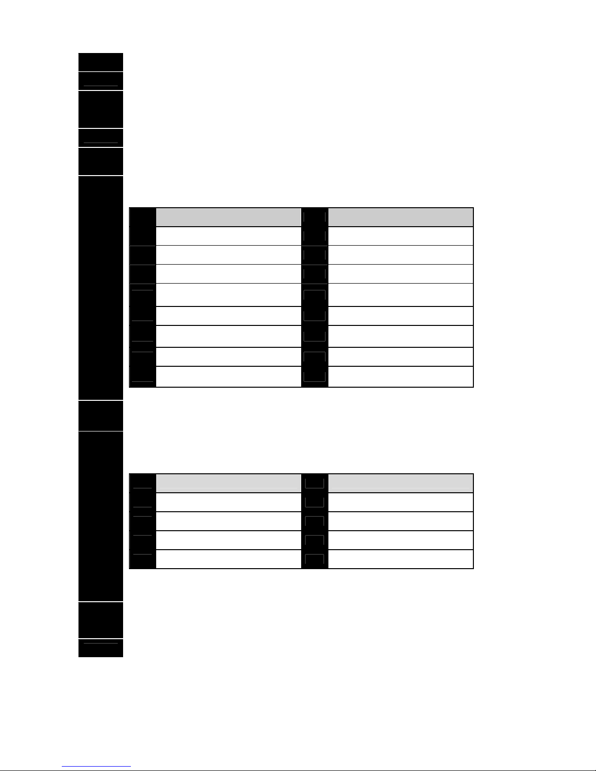
LED Attributes if LED 8 is off LED Attributes if LED 8 is on
1
Reserved
1
Activate output 1
2
Arm Only
2
Activate output 2
3
Arm Only After Close Window
3
Activate output 3
4
Master arm/disarm (can program
other codes)
4
Activate output 4
5
Arm/disarm code
5
Arm/disarm
6
Allowed to bypass zones (see F23)
6
Bypass zones
7
Code will send open / close reports
7
Open / Close reporting
8
If LED 8 is off, LEDs 1-7 will use the
details in this column
8
If LED 8 is on, LEDs 1-7 will use the
details in this column
Note you cannot set attributes on both sides of the table above (e.g. Arm Only and Activate output 3).
Step 7
Press the [Á] key. The ready light will flash. This moves you to the area enab le.
(The user has access to areas that are illuminated by the LEDs.)
Step 8
The illuminated numbers indicate each area where the user has access. To change any of the areas
where the user has access, press numbers corresponding to areas where you want to give the user
access or deny access. Refer to chart shown below:
LED Areas Assigned LED Areas Assigned
1
Area 1
5
Area 5
2
Area 2
6
Area 6
3
Area 3
7
Area 7
4
Area 4
8
Area 8
Example: If zone LED 2 is lit, then the user is assigned access to area 2. By pressing the [2] key, the
light will go off, denying access to area 2.
Step 9
When the areas are assigned, press the [Á] key, returning you to Step 4. You may then enter another
user number to assign authority level. Repeat Steps 4 - 8 until you have assigned authority levels to all
user numbers.
Step 10 Press the [#] key to exit the Assigning Authority Level Program.
Note: Any master arm/disarm code can add or change a user code if the master code has access to the sa me areas as the
code being added/changed. Consequently, when programming the user codes for such a system, leave at least one code
(can be ‘Go To Program Code’ if enabled in Feature 2) access to all areas or you w ill not be able to add new users. If you
desire the end user to be able to add new codes, you must remove the area authority from all blank codes.
Page 21

© Hills Industries 2006 Page 19
10. Walk Test Mode - Function [Á] [Chime]
Step 1 Press the [Á]-[Chime] keys
Step 2
Enter a [Master Arm/Disarm Code]
Now all zones become 24 hour, silent and local (non r epo rting zo nes). By faulting a ny zone, that zone will
latch its zone light on the LED code pad, and sound the Chime. The Chime will continue to sound each
time a zone is faulted. Once all zone are tested (zone lights lit on the LED code pad) go to step 3.
Step 3 Enter a [Master Arm/Disarm Code]
11. Call Back Download [Á] [9] [8] and Answer Call [Á] [9] [9]
Step 1
Pressing [Á]-[9]-[8] while the system is disarmed will cause the control p anel to initiate a call back for a
download connection (remote access). Note: a valid user code may be required after [Á]-[9]-[8] if
enabled in Feature 0.
Pressing [Á]-[9]-[9] while the system is disarmed will cause the control panel to seize the pho ne line for
a download connection (remote access). Note: a valid user code may be required after [Á]-[9]-[9] if
enabled in Feature 0.
Page 22

© Hills Industries 2006 Page 20
Programming The Hills Reliance Control Panel
Features, Segments and Options
The Hills Reliance programming structure consists of Features, Segments, and Options.
Features or Feature numbers are used to locate an option or group of options.
Example: Feature 6 contains the communicator format selection and Feature 16 co ntains area one options.
Segments are contained within each feature, there are two types of segments.
The first segment type is referred to as an option select segment. This segment type contains up to eight options that can
be toggled On or Off like dip switches.
The second segment type is referred to as a numeric segment. This segment type requires a value from ‘0’ to ‘255’ to be
entered.
Options are contained within segments. An option select segment can have up to eight options. A numeric segment can
have a value of ‘0’ to ‘255’.
Example: Feature 6 contains the communicator format that has one segment with one option; and Feature 16 contains area
one options that has 5 segments with 40 options in total.
Navigating Program Mode
Entering The Program Mode: To enter the program Mode, press [r]-[8]. At this time, the five function LEDs (On, Partial,
Exit, Bypass, & Chime) will begin to flash. Next, enter the ‘Go To Program Code’ (factory default is [9]-[7]-[1]-[3]). If the ‘Go
To Program Code’ is valid, the ‘Service’ LED will flash and the five fu nction LEDs will illumin ate steady. You are no w in the
Program Mode and ready to select the module to program.
Selecting The Module To Program: Since all modules connected to the Hills Reliance are programmed throug h the code
pad, the module you are programming should be the first entr y. To program the Hills Reliance control panel, e nter [0]-[#].
[0] is the module number of the control and the [#] is the enter key. Other module e ntry numbers can be found in their
corresponding manuals.
Programming A Feature: Once the number of the module to be programmed has been entered, the ‘Armed’ LED will
illuminate, indicating it is waiting for a programming feature to be entered. Any feature can be accessed by directly entering
the desired programming feature followed by the hash [#] k ey. If the feature entered is a valid feat ure, the ‘Armed’ LED will
extinguish, the ‘Ready’ LED will illuminate a nd the bi nary data for the first s egment of this feature will be sho wn by the zone
LED's. While entering new data, the ‘Ready’ LED will begin flashing to indicate a data c hange in proc ess. The flashing will
continue until the new data is stored by pressing the [Á] key. Upon pressing the [Á] key, the code pad will adva nce to the
next segment and display its data. This procedure is repeated until the last segme nt is reached. Pressing the [#] key will
exit from this feature, and the ‘Armed’ LED will illuminate again waiting for a ne w programming feature to be entered. If the
desired feature is the next sequential feature, press the [POLICE] key. If the previous feature is desired press the [FIRE]
key. If the same feature is desired press the [MEDICAL] key. To review the data in a feature, repeat the a bove procedure,
pressing the [#] key without any numeric data entry. Each time the [r] key is pressed, the programming data of the next
segment will be displayed for review.
Exiting A Feature: After the last segment of a feature is programmed, pressing the [Á] key will exit that feature, turn the
‘Ready’ LED off and the ‘Armed’ LED on. You are now ready to enter another programmi ng feature as before. If an attempt
is made to program an invalid entry for a particular segment, the code pad sounder will emit a triple error beep (b eep, beep,
beep), and remain in that segment awaiting a valid entry.
Exiting The Program Mode: When all the desired changes in programming have been made, it is time to exit the progr am
mode. Pressing the [Exit] key will exit this programming level, and go to the ‘Select a Module to Program’ level. If no
additional modules are to be programmed, pressing th e [Exit] key agai n will e xit the program mo de. If there is a module t o
be programmed, it may be selected by entering its address followed by the [#] key (see ‘Selecting the Module T o Program’
above). The procedure for programming these devices is the same as for the control panel, except the features will be for
the module selected.
Page 23

© Hills Industries 2006 Page 21
Programming Data
Programming Data: Programming data is always one of two types. One type of d ata is numerical and can tak e on values
from 0-15 or 0-255 depending on the feature's segment. The other type of data is a O ption selection type. Option selection
data is used to turn options on or off. Use the following procedures when working with these two data types:
Numerical Data: Numerical data is programmed by entering a number from 0-255 on the numeric keys of the system code
pad. To view the data in a feature, a binary process is used. W ith this process, the LED’s for zones 1 through 8 are
utilized, and the numeric equivalents of their illuminated LE D’s are added together to determine the data in a pr ogramming
feature. The numeric equivalents of these LED’s are as follows:
Zone 1 LED = 1 Zone 2 LED = 2 Zone 3 LED = 4 Zone 4 LED = 8
Zone 5 LED = 16 Zone 6 LED = 32 Zone 7 LED = 64 Zone 8 LED = 128
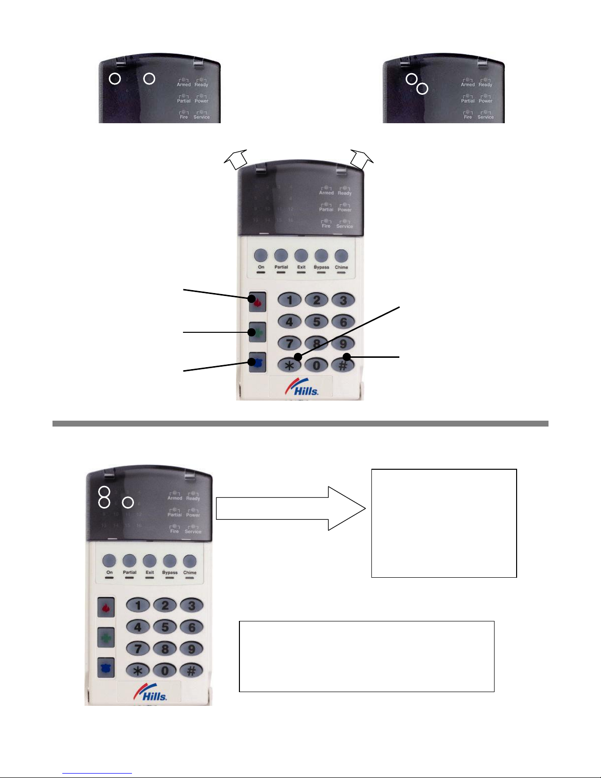
Example: If the numerical data to be programmed in a feature is ‘ 66’, press [6]-[6] on the code pa d. The LED’s for zone 2
and Zone 7 will become illuminated indicating 66 is in that feature (2 + 64 = 66). See this example on page 22.
Once the data is programmed, press the [r] key to enter the data and advance to the next segment of that feature. After
the last segment of a feature is programmed, pressing the [r] key will exit that feature, turn the ‘Ready’ LED off and the
‘Armed’ LED on. As before, you are now ready to enter another programming feature. If an attempt is made to program a
number too large for a particular segment, the code pad sounder will emit a triple beep, indicating an error, and remain in
that segment awaiting a valid entry.
Option Selection Data: Option selection data will display the current conditio n (on or off) of eight options associated with
the programming feature and segment selected. Pressing a button on the touch-pad (1 thru 8) that corresponds to the
‘option number’ within a segment, will toggle (on/off) that opt ion. Press ing a ny num eric key between [1] and [8] for selection
of a option, will make the corresponding LED illuminate (opt ion ON). Press the number again and the LED will extinguish
(option OFF). You will see that numerous options can be selected from within one segment. For instance, if all eight
options of a segment are desired, pressing [1]-[2]-[3]-[4]-[5]-[6]-[7]-[8] will turn on LED's 1 thru 8 as you press the keys,
indicating that those options are enabled. After the desired setting of options is selected for this segment, press the [Á] key.
This will enter the data and automatically advance to the next segment of the feature. When yo u are in the last segment of a
feature and press the [Á] to enter the data, you will exit that feature. This will now turn the ‘ Ready’ LE D off and the ‘ Armed’
LED on. As before, you are now ready to enter another programming feature.
Loading Factory Defaults
There are two methods of loading the factory defaults:
Method 1 - Enter the program mode using the procedure on page 9, then type [9]-[1]-[0]-[#]. The code pad will beep 3
times indicating that the loading is in progress. The loading takes about 6 seconds.
Method 2 - Enter [9]-[7]-[1]-[3]-[0]-[0] within 10 seconds of power up at any code pad which is not programmed for
master mode. The procedure will default the Hills Reliance control panel even if it is armed.
Enrolling Modules & Code Pads
For supervision purposes, the Hills Reliance has the ability to automatically find and store in its memor y, the presence of all
code pads, zone expanders, wireless receivers, and any other module connected to the data termina l (KP DATA) whenever
exiting the program mode. The enrolling process takes about 12 seconds, during which time the ‘Service’ LED will
illuminate. Once a module is enrolled, if it is not detected by the control panel, the ‘Service’ LED will illuminate on that code
pad.
To force module and keypad enrolment, whilst in program mode enter [9]-[1]-[5]-[#]-[Exit]-[Exit], and wait 12 seconds.
Page 24
© Hills Industries 2006 Page 22
Programming Example Figure1 - Numerical Data (Binary)
Programming Example Figure 2 - Option Selection Data
Enters the previous
programming “feature”
Returns to the “feature”
j
ust programmed.
Advances to the next
programming “feature”
To change data in a segment,
enter the data followed by [À]
Pressing [#] will exit a feature
without changing the data in
the current segment
Zone 1 LED = 1
Zone 4 LED = 8
}
Data = 9
Zone 2 LED = 2
Zone 7 LED = 64
}
Data = 66
Feature 16 - Segment 1
1 = Quick Arm
2 = Re-Exit
3 = Force Arm
4 = Silent Code Pad Panic
5 = Audible Code Pad Panic
6 = Code Pad Fire
7 = Code Pad Medical
8 = Code Pad Multiple
9 = Code Attempt Tamper
LEDs show Options enabled
Press the key on the numeric Code Pad that corresponds
to the option you wish to enable/disable. When an LED is
“on”, an option is enabled; when “off” the option is
disabled. For example: With the 1, 5, & 7 LEDs “on”,
Quick Arm, Audible Code Pad Panic and Code Pad
Medical are enabled.
1 4
2
7
1
5 7
Page 25
© Hills Industries 2006 Page 23
Programming Feature Descriptions
System Codes
Feature 0 Code Requirements
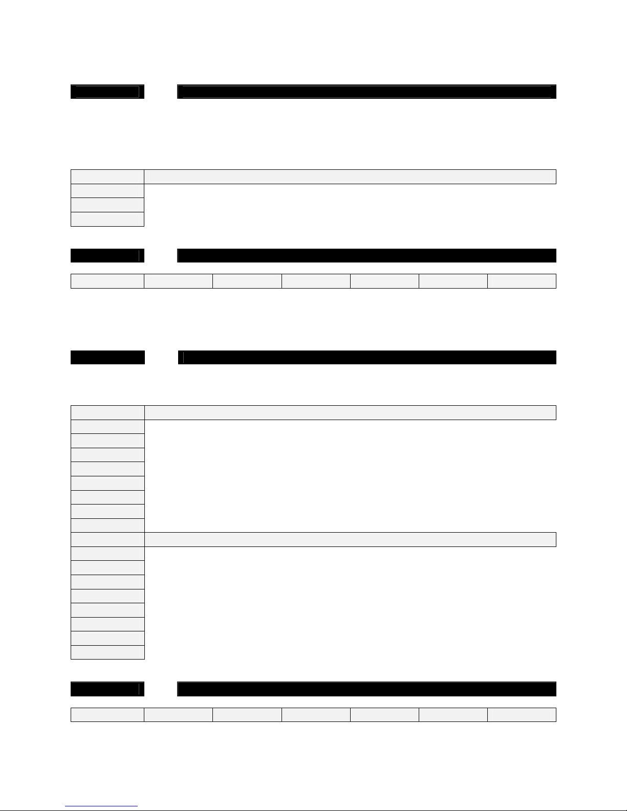
Feature 0, segment 1 is used to enable the 6 digit user code option. If 6-digit o ption is enabled, all arm/disarm codes, the
‘Go To Program Code’ and duress code are 6 digits. If this option is e nabled, the default user 1 code is [1]-[2]-[3]-[4]-[5]-
[6]. The Hills Reliance 128 has 99 four (4) digit user codes or 66 six (6) digit user codes, the Hills Reliance 12 has 40
codes, the Hills Reliance 8 has 8 codes. Segment 2 is used to enable user code requirement for functions [Á]-[9]-[8]
(perform call back download) and [Á]-[9]-[9] (answer incoming call for download).
Segment 1
1
On enables the 6-digit code option. Its original off state is a 4-digit code.
2 On requires code entry for [Á]-[9]-[8] and [Á]-[9]-[9] functions
3 –8
Reserved
Feature 1 Go to Program Code
Segments 1-6
9 7 1 3 0 0
Feature 1 contains the ‘Go To Program Code’. This featur e contains either a 4 or 6-di git code. If the 6-digit code option is
enabled in Feature 0, this code must contain six (6) digits. If this option is not enabled i n Feature 0, the last 2 segments
(digits) will be ignored. With the panel disarmed, the ‘Go To Program Code’ can be used to enter the program mode.
Feature 2 Go To Program Code Area and Authorisation
The ‘Go To Program Code’ can be used as a standard arm/disarm code. W hen using the code to arm or disarm, the user
I.D. is 255. (This code may not be changed in the run mode.)
Segment 1
1
Reserved
2
On enables ‘Go To Program Code’ as an arm only code
3
On enables ‘Go To Program Code’ as an arm only after closing
(4)
On enables ‘Go To Program Code’ as a master code (can change user codes)
5
On enables ‘Go To Program Code’ as an arm/disarm code
6
On enables ‘Go To Program Code’ to bypass zones
7
On enables ‘Go To Program Code’ opening and closing reports
8
Reserved
Segment 2
(1)
On enables the ‘Go To Program Code’ for area #1
(2)
On enables the ‘Go To Program Code’ for area #2
(3)
On enables the ‘Go To Program Code’ for area #3
(4)
On enables the ‘Go To Program Code’ for area #4
(5)
On enables the ‘Go To Program Code’ for area #5
(6)
On enables the ‘Go To Program Code’ for area #6
(7)
On enables the ‘Go To Program Code’ for area #7
(8)
On enables the ‘Go To Program Code’ for area #8
Feature 3 Duress Code
Segments 1-6
15 15 15 15 15 15
Feature 3 contains the ‘Duress’ code. This feature contains either 4 or 6 digits. If the 6-digit code option is enabled in
Feature 0, This code must contain six (6) digits. If the 6-digit option is not enabled in Feature 0, the last 2 digits will be
ignored. If the duress code is programmed, it will work for all areas.
Page 26
© Hills Industries 2006 Page 24
Dialer Options (Features 4 – 11)
Feature 4 Phone Number One (1)
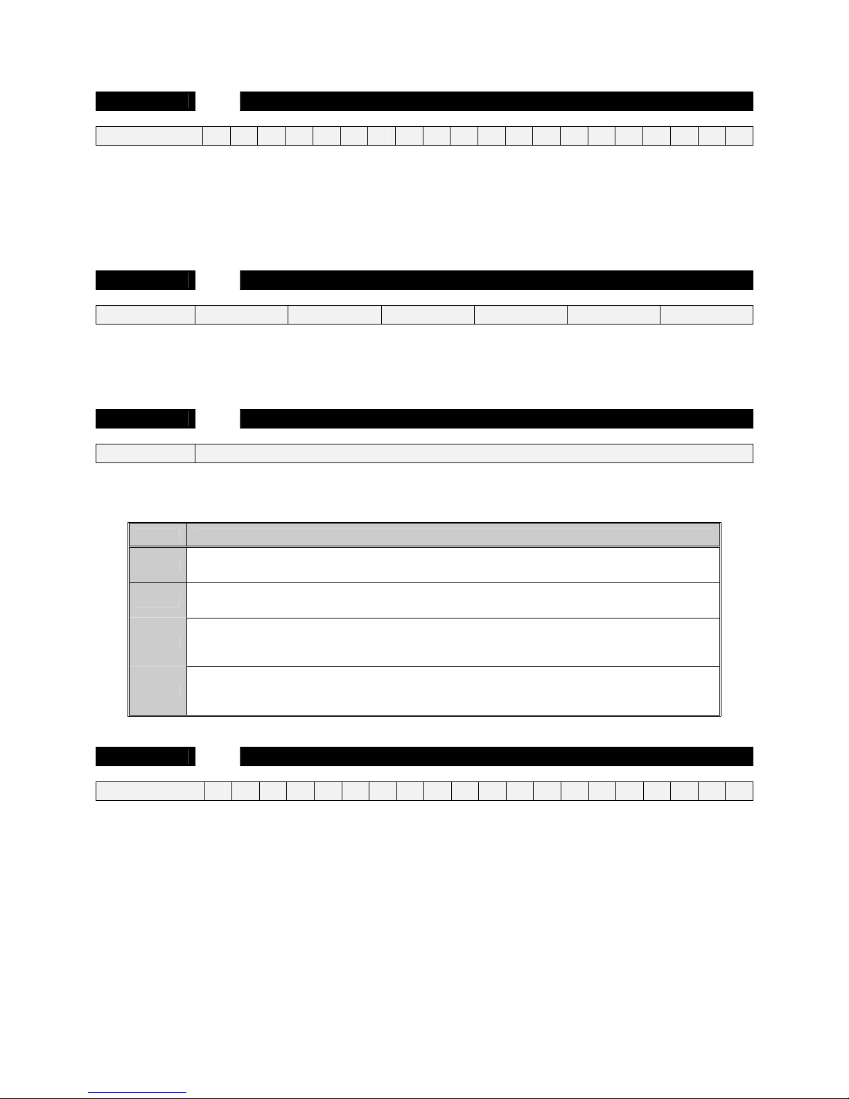
Segments 1-20
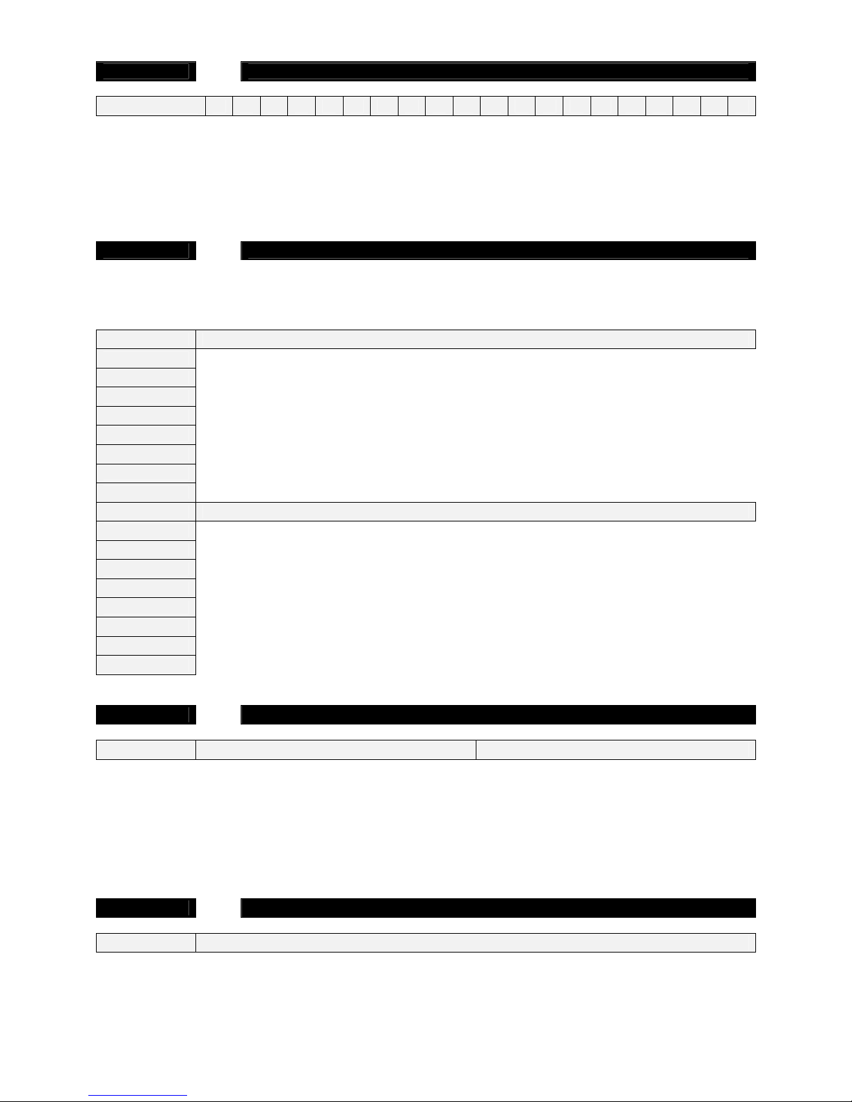
14 14 14 14 14 14 14 14 14 14 14 14 14 14 14 14 14 14 14 14
The first telephone number is programmed in Feature 4.
’15’ = pulse dialling - in the segment where pulse dialling should begin
’14’ indicates the end of the phone number. Fill all empty segments after end of dialling with ‘14’
’13’ = four second delay - in the segment where a delay is required
’12’ = a ‘#’ - in the segment as required
‘11’ = for a ‘Á’ - in the segment as required
Feature 5
new
System Account Code
Segments 1-6
10 10 10 10 Reserved
new
Reserved
new
This is the account code sent for any area event (open/close and zone related alar ms) that does not have its account code
programmed. System events (siren/box tampers, expander troubles, etc.) will use the system account unless area one
account is programmed.
Feature 6 Communicator Format
Segment 1
0
Feature 6 contains the communicator format used. Select a format from the format selection table. If this feature contains a
‘0’, the built-in communicator will be disabled, and the panel will function as a local onl y control.
Data Communicator Format
0
Local
Communicator is disabled
1
Contact I.D.
DTMF format for control rooms
2
Pager
Reports in 4 + 2 DTMF format. Phone numbers can be programmed via code pad in normal
operation.
3
Domestic Siren
Domestic dialling via a siren tone format. Call can be kissed off via the star (Á) key on a DTMF
phone. Phone numbers can be programmed via code pad in the run mode.
Feature 7 Phone Number Two (2)
Segments 1-20
14 14 14 14 14 14 14 14 14 14 14 14 14 14 14 14 14 14 14 14
The second telephone number is programmed in Feature 7.
’15’ = pulse dialling - in the segment where pulse dialling should begin
’14’ indicates the end of the phone number. Fill all empty segments after end of dialling with ‘14’
’13’ = four second delay - in the segment where a delay is required
’12’ = a ‘#’ - in the segment as required
‘11’ = for a ‘Á’ - in the segment as required
Page 27
© Hills Industries 2006 Page 25
Feature 8 Phone Number Three (3)
Segments 1-20
14 14 14 14 14 14 14 14 14 14 14 14 14 14 14 14 14 14 14 14
The third telephone number is programmed in Feature 8.
’15’ = pulse dialling - in the segment where pulse dialling should begin
’14’ indicates the end of the phone number. Fill all empty segments after end of dialling with ‘14’
’13’ = four second delay - in the segment where a delay is required
’12’ = a ‘#’ - in the segment as required
‘11’ = for a ‘Á’ - in the segment as required
Feature 9 Event Report Summary
Feature 9 is a summary of event reporting codes found in the area and system features. Area report events are enabled in
area options, but will also need to be enabled in this feature. This approach is used to simplify event selection
programming.
Segment 1
(1)
Alarms
(2)
Alarm Restores
3
Opening / Closing (alarm system disarmed = open, alarm system armed = close)
(4)
Bypass and Bypass Restore
5
Zone Trouble and Restore
(6)
Power Trouble (AC Failure or Low Battery) and Restore
7
Tampers and Restore (Zone, Box and Code Pad)
(8)
Test Reports
Segment 2
(1)
System Trouble (siren / phone / expander / short circuit) and Restore
(2)
Failure to Communicate
(3)
Sensor Lost / Sensor Low Battery
4
Program, Download, & Full Log (Full Log must also be enabled in system options)
(5)
Cancel Code (Cancel reporting must also be enabled in area options)
6
Recent Closing / Exit Error
7
Reserved
8
Reserved
Feature 10 Dial Attempts and Dialing Options
Segments 1-2 6 0
Feature 10, Segment 1 is used to enter the number of dial attempts (1 to 15 attempts) the communicator will make to phon e
#1 before ending the notification process. Factory default is ‘6’ and the communicator will make 6 attempts to the first
number.
Feature 10, Segment 2 configures additional functionality. Factory default is “0” – no function.
A value of “1” enables Dual Reports – sends reports to both phone number 1 & 2.
A value of “4” enables extended phone number and joins Feature 4 & 7 together for a 40 digit phone number.
Feature 11 Phone Line Cut Delay
Segment 1 0
Feature 11 contains the number of second increments in the telephone line monitor delay before phone line fault is
activated. The telephone line monitor delay can be programmed in 1 second increments from 1 to 255 seconds.
Note: The Hills Reliance 128 and 12 internal phone line monitoring circuit requires approximate ly 5 seconds to discharge
before it senses a missing phone line, you must add this time to the value in this feature when testing this option. A value of
“0” = disabled.
Page 28
© Hills Industries 2006 Page 26
Download Options (Features 12 – 15)
Feature 12 Download Access Code
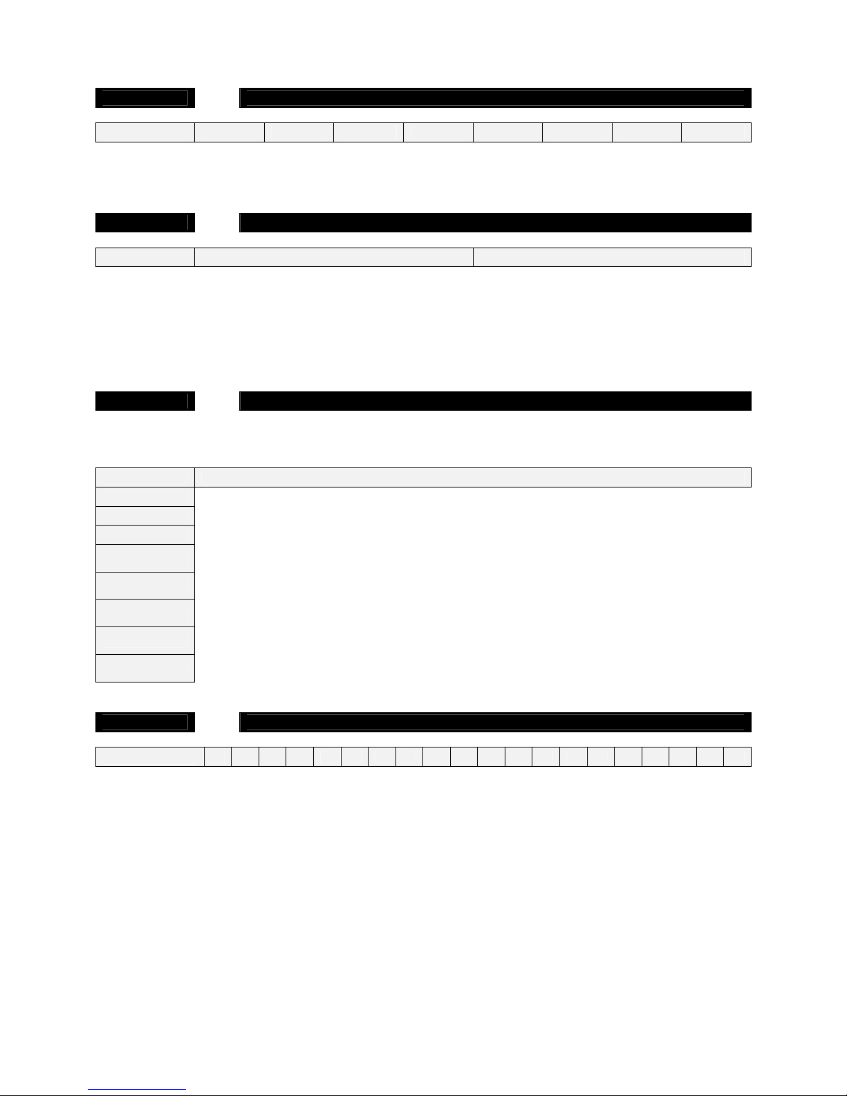
Segments 1-8 1 6 0 0 0 0 0 0
Feature 12 contains the eight digit access code the panel must receive from the downloading soft ware before the panel will
permit downloading to occur.
Feature 13 Number of Rings (Seg 1) / Number of Calls to Answer (Seg 2)
Segments 1-2 0 0
Feature 13, segment 1 contains the number of rings the panel must detect before answering the telephone line when
initiating a download session. A value of 1 to 15 can be entered in this segment. Segment 2 conta ins the number of calls
the panel must detect before accepting the number of rings in segment 1. A value of 1 to 15 can be entered in this segment.
A call is satisfied by one (1) or more rings, and then an eight (8) second period of no ringing. The next call must then be
made within 45 seconds. The total number of calls must be reached before the panel will c ount for the number of rings (in
segment 1) during the necessary subsequent call. A value of “0” = disabled.
Feature 14 Download Control
Feature 14 contains the option selections for the controlling of download sessions. The following options can be enabled or
disabled using this feature.
Segment 1
1
On enables two call Answering Machine Defeat (see page 28 for a full explanatio n of this option).
2
Reserved
3
On enables Call Back Before Download Session (see Feature 15).
4
On enables Control Panel Shutdown
(Can only be viewed from the code pad, must be changed through downloading).
5
On locks all local programming
(Can only be viewed from the code pad, must be changed through downloading).
6
On locks programming of all features associated with the communicator
(Can only be viewed from the code pad, must be changed through downloading).
7
On locks out download section. (If ‘On’, Features 12-15 cannot be viewed from the code pad)
Note: This segment can only be changed through the download software.
8
On enables Call Back at Auto Test Interval to perform download software automatic functions
(Refer to your download software help for a full explanation of this option).
Feature 15 Call Back Number
Segments 1-20
14 14 14 14 14 14 14 14 14 14 14 14 14 14 14 14 14 14 14 14
If a telephone number is programmed into this feature, and “Call Back Before Do wnload Session” is en abled in Feature 14 ,
the control panel will hang up for approximately 10 seconds and then call back. If pulse di alling is d esir ed, program a ‘1 5’ in
the segment where pulse dialling should begin. If the entir e number should be pulse dialling, program a ‘15’ in the first
segment. Four-second delays can be obtained anywhere in the sequ ence by programming a ‘13’ in the appro priate delay
feature.
Warning: the call back phone number should always be reviewed for accuracy before disconnecting!
Page 29
© Hills Industries 2006 Page 27
Feature 16
new
Area 1 – Option and Report Selections
Feature 16 is used to enable certain options for this area and code pads in this area. In addition, cert ain communicator
reports are enabled in Feature 16. Each of these opti ons can be enabled by area. For additional area information see
Features 37-58 on pages 40-44. If the option selection feature for an y area i s left blan k, that area will use this feature
for the option selection. This feature contains 5 segments of 8 options each.
Segment 1
(1)
On enables the Quick Arm option
(2)
On enables the Re-exit option
3
On enables the Force Arm option
4
On enables the Silent Code Pad Panic option
(5)
On enables the Audible Code Pad Panic option
(6)
On enables the Code Pad Fire option
(7)
On enables the Code Pad Medical option
8
On enables the Code Pad Multiple Code Attempt Tamper option
Segment 2
1
On enables the LED Extinguish option
2
On enables the Require Code for Bypassing option
3
On enables the Zone Bypassed Sounder Alert option
(4)
On enables the AC Power/Low Battery Sounder Alert option
(5)
On enables Bypass toggle
6
On enables Silent Auto Arm
7
On enables the Universal Arming option
8
On enables the One Key Partial Mode Disarm
Segment 3
(1)
On enables Opening and Closing reports
(2)
On enables Zone Bypass reporting
(3)
On enables Zone Restore reporting
(4)
On enables Zone Trouble reporting
(5)
On enables Zone Tamper reporting
6
On enables the Cancel option
(7)
On enables Recent Closing option
(8)
On enables Exit Error option
Segment 4
new
1
new
On enables Late To Close (requires Feature 6 to be set to Contact ID)
2
new
On enables Auto Arm In Partial
3
new
Reserved
4
new
On enables Disable Bypass For Force Arm Zones
5
new
Reserved
6
new
Reserved
7
new
Reserved
8
new
Reserved
Segment 5
new
1
new
Reserved
2
new
Reserved
3
new
Reserved
4
new
Reserved
5
new
Reserved
6
new
Reserved
7
new
Reserved
8
new
Reserved
Page 30

© Hills Industries 2006 Page 28
Area Option Descriptions
AC Power / Low Battery Sounder Alert
If enabled, the panel will beep the Code Pad sounder upon arming or disarming if the AC power is missing or a lo w battery
has been detected.
Answering Machine Defeat
If enabled, the DL900 software calling the panel will ri ng (briefly), hang up and ring (briefly) again. The sequence will be
repeated as many times as programmed in Feature 13
. Answering machines usually ans wer calls after a long ring period .
The Answering Machine Defeat feature prevents the answering machine from answering the call from the DL900 software.
Bypass Code
If enabled, the panel will require a valid user code to be entered during the zone bypass function.
Cancel
If enabled, the panel will send a ‘Cancel’ report when the s ystem is disarmed by a valid user after an alarm activation. The
cancel code followed by the user number.
Code Pad Activated Panics
The panel has three Code Pad activated panics that will send reports to the central station: Fir e, Medical, and Code Pad
Panic. The Fire key will activate the steady (Fire) siren, th e Medical key will sound the Code Pad (the Medical key can be
set for silent activation in system options), and the Code Pad Panic can be programmed to b e silent or audible (sound
siren).
Code Pad Tamper
If enabled, the panel will disable the Code Pad for 60 s econds and communic ate a tamper signal to the central station if 30
key-presses are entered without producing a valid code. The Code Pad sounder will remain functi onal.
Exit Error
If enabled, the panel will send an ‘Exit Error Report’ if an entr y/exit zone i s faulted at the instant the e xit delay expires. This
report will be sent along with the user number that armed the system, if the panel is not disarmed before the entry delay
expires. The alarm report will also be sent. Even if this option is not enabled, the siren will sound if any entry/exit zone is
faulted at the instant the entry delay expires. This option is ena bled b y default, b ut needs to be set to r eport in Feat ure 9 f or
proper operation.
Force Arming
When enabled, the panel can be Force Armed with zones faulted. Under this condition, if a force arm zone is not secure,
the ‘Ready’ LED will flash. At the end of the exit d elay, these zones will become b ypassed. If these zones become sec ured
any time during the arming cycle, they will be un-bypassed and remain active in the system. If ‘Bypass Report’ is enabled,
the force arming zones can be programmed to report bypass when they are Force Armed (default), or to not report bypass
even if ‘Bypass Report’ is enabled (refer to system options).
Group Bypass
A designated group of zones can be programmed to bypass by pressing [Bypass]-[0]-[0]-[Bypass] prior to arming.
Group Toggle
If enabled, the panel can toggle the Group Bypass zone in and out of bypass mode by pressin g the [Bypass] key. This
option if active when ever the panel is in either Partial or Full Arm mode.
LED Extinguish
This option will extinguish all LEDs on the Code Pad, except the ‘Power’ LED, after 60 seconds without a key-press.
Pressing any numeric key will illuminate all LEDs.
One Key Partial Mode Disarm
If enabled, the panel can be disarmed from the Partial Mode by pressing the Partial key.
If disabled, the panel requires a full user code to be entered to disarm the system.
Partial Mode
Partial mode allows system owners to arm only designated partial zones ( e.g. downstairs, front doors, garage), bypassing
all non-partial zones (e.g. upstairs bedroom). Partial mode encourages system owners to use their alarm system more
frequently when the premise is occupied. When armed in the ‘Partial’ mode, the opening of any zones designated as ‘Partial
Mode zone’ will initiate the code pad sounder and start the P artial Mode entry delay before creating an alarm. All other
zones will be bypassed during Partial mode. To arm this area in Partial Mode, press the [Partial] key on the code pad.
Quick Arm Option
The panel has a one button ‘Quick Arm’ option that can be used to arm the system by pressing the [ON] key on the Code
Pad. If closing reports are sent, the user code will be 98.
Recent Closing
If enabled, the panel will send a ‘Recent Closing Report’ to the central station if an alarm occurs within 5 minutes after the
panel is armed. The user number that armed the s ystem will also be sent. This option is e nabled by default, but needs to
be set to report in Feature 9 for proper operation.
Page 31
© Hills Industries 2006 Page 29
Area Option Descriptions
Re-exit
The panel has the ability to restart the exit delay if required without disarming the system by pressing the [Exit] key while
the system is running the exit delay. This option can only be used once per arming cycle.
Silent Automatic Arming
If enabled, the panel will Auto Arm this area and not activate the 50 second code pad s ound. This option is us ed when you
don’t want to alert any other area of your Auto Arm time.
Universal Arming
When enabled, using the quick arm function (ON button on code pad) or entering a valid user code will automatically arm
the panel in Partial mode if an exit zone is not faulted during the exit delay time.
Zone Bypassed Sounder Alert
If this option is enabled, the panel will beep the Code Pad sounder upon arming if a zone is bypassed.
Late To Close Reports
new
If this option is enabled, the panel will send a Late To Clos e report to the central monitoring station if Contact ID is enabl ed
in Feature 6 and the panel has not been armed by the Closing Time in Feature 34.
Autoarm In Partial
new
If this option is enabled and Auto Arming is enabled in F eature 36 then the panel will Auto Arm in partial mode at the
Closing time set in Feature 34.
Disable Bypass For Force Arm Zones
new
If this option is enabled then at the end of the Exit Delay if any Force Arm type zones are unsealed they will not be
bypassed and the zone will activate the alarm as per its Zone Configuration Type characteristic.
Feature 17
new
Area 1 – Entry / Exit Timers
Entry Time 1 Exit Time 1 Entry Time 2 Exit Time 2
Segments 1-6 30 60 30 60
Reserved
new
Reserved
new
Feature 17 sets the primary and secondary entry / exit times for area 1. Valid entries are 10-255 seco nds
Zones 1 – 8 Configuration
Feature 18 Zones 1-8 Configuration Group
Segments 1-8 3 7 16 16 16 16 16 16
Feature 18 contains the Configuration Group (zone type) for zones 1-8. Segment 1 is for zone 1, and Segment 8 is for zone
8. Refer to the ‘Default Zone Configuration’ table in this section for zone type selections.
Default Zone Configurations
Zones can be programmed to be one of thirty different zone configurations (zone types). Configurations 1 to 20 can be
modified in the configuration group section of this manual. Configuration groups 21 to 30 are factory set and cannot be
altered. Choose one of the 30 default zone configurations to program into each of the zone configuration segments (e.g.
features 18, 20, 59, 61, 63, 65, 119, 121, etc). Study this table for the appropriate zone configuration group for each zone.
Data Default Zone Configuration
1
Entry / Exit Delay 1: Partial – Forced Arming – A trip will start entry delay 1. This zone will be
active in partial mode. This zone type may be faulted while arming if forced arming is enabled in the
area options.
2
Entry / Exit Delay 1: Chime – Forced Arming – A trip will start entry delay 1. This zone will be
bypassed in partial mode. This zone type will set the c ode p ad c hime if set via the co de pad [Chime]
key.
3
Entry / Exit Delay 1: Partial – Chime – Forced Arming – A trip will start entry delay 1. This zone
will be active in partial mode. This zone type may be faulted while arming if forced arming is enable d
in the area options. This zone type will set the code pad chime if set via the code pad [Chime] key.
Page 32
© Hills Industries 2006 Page 30
Data Default Zone Configuration
4
Entry / Exit Delay 2: Partial – Forced Arming – A trip will start entry delay 2. This zone will be
active in partial mode. This zone type may be faulted while arming if forced arming is enabled in the
area options.
5
Entry / Exit Delay 2: Partial – Chime – Forced Arming - A trip will start entry dela y 2. This zone
will be active in partial mode. This zone type may be faulted while arming if forced arming is enable d
in the area options. This zone type will set the code pad chime if set via the code pad [Chime] key.
6
Handover: Forced Arming – Interior zone that follows the e ntry delay zones. Instant alarm type
unless an entry zone if faulted first. This zone will be b ypassed in partial mode. This zone t ype may
be faulted while arming if forced arming is enabled in the area options.
7
Handover: Partial – Forced Arming – Interior zone that follows the entry delay zones. Instant alarm
type unless an entry zone if faulted first. This zone will be active in partial mode. This zone t ype ma y
be faulted while arming if forced arming is enabled in the area options.
8
Handover: Twin Trip – Forced Arming – Interior zone that follows the entry delay zones. Instant
alarm type unless an entry zone if faulted first. This zone will be bypassed in partial mode. This zone
type may be faulted while arming if forced arming is enabled in the area options. This zone type will
require two triggers or another zone would have to have been trigged before it will activate an alarm.
9
Handover: Group Isolate – Forced Arming – Interior zone that follows the entry delay zones.
Instant alarm type unless an entry zone if faulted first. This zone will be bypassed in partial mode.
This zone type may be faulted while arming if forced arming is enabled i n the area options. This zone
type will be part of the group bypass zones.
10
Handover: Twin Trip – Chime – Forced Arming – Interior zone that fo llows the entry d elay zones.
Instant alarm type unless an entry zone if faulted first. This zone will be bypassed in partial mode.
This zone type may be faulted while arming if forced arming is enabled i n the area options. This zone
type will require two triggers or another zone would have to have been trigged before it will activat e
an alarm. This zone type will set the code pad chime if set via the code pad [Chime] key.
11
Handover: Partial – Twin Trip – Forced Arming – Interior zone that follows the entry delay zones.
Instant alarm type unless an entry zone if faulted first. This zone will be active in partial mode. This
zone type may be faulted while arming if forced arming is enabled in the area options. This zone type
will require two triggers or another zone would hav e to have been trigged before it will activate an
alarm.
12
Handover: Partial – Group Bypass – Forced Arming – Interior zone that follows entry delay
zones. Instant alarm type unless an entry zone if faulted first. This zone will be active in partial mode.
This zone type may be faulted while arming if forced arming is enabled i n the area options. This zone
type will be part of the group bypass zones.
13
Handover: Twin Trip – Group Bypass – Forced Arming – Interior zone that follows the entry delay
zones. Instant alarm type unless an entry zone if faulted first. This zone will be bypassed in partial
mode. This zone type may be faulted while arming if forced arming is enabled in the area options.
This zone type will require two triggers or another zone would have to have been trigged before it will
activate an alarm. This zone type will be part of the group bypass zones.
14
Handover: Partial – Twin Trip – Group Isolate – Forced Arming – Interior zone that follows the
entry delay zones. Instant alarm type unless an entry zone if faulted first. This zone will be active in
partial mode. This zone type may be faulted while arming if forced arming is enabled in the area
options. This zone type will require two triggers or an other zone would have to have been trigged
before it will activate an alarm. This zone type will be part of the group bypass zones.
15
Instant: – Produces an instant alarm if tripped when armed. Ignored when disarmed. This zone will
be bypassed in partial mode.
16
Instant: Partial – Produces an instant alarm if tripped when arm ed. Ignored when disarmed. This
zone will be active in partial mode.
17
Instant: Partial (no DEOL) – Produces an instant alarm if tripped when armed. Ignored when
disarmed. This zone will be active in partial mode. This zone t ype will not be en abled for dual end of
line monitoring if enabled in the system options.
18
Instant: Twin Trip – Forced Arming – Produces an instant alarm if tripped when armed. Ign ored
when disarmed. This zone will be bypassed in partial m ode. This zone type may be faulted while
arming if forced arming is enabled in the area options. This zone type will require t wo triggers or
another zone would have to have been trigged before it will activate an alarm.
19
Instant: Group Bypass – Produces an instant alarm if tripped when armed. Ign ored when disarmed.
This zone will be bypassed in partial mode. This zone type will be part of the group bypass zones.
20
Instant: Partial – Chime – Produces an instant alarm if tripped when armed. Ignored when
disarmed. This zone will be active in partial mode. This zone type will set the code p ad chime if set
via the code pad [Chime] key.
Page 33
© Hills Industries 2006 Page 31
Data Default Zone Configuration (Zones 21-30 are not reprogrammable)
21
Instant: Partial – Twin Trip – Produces an instant alarm if tripped when armed. Ignored when
disarmed. This zone will be bypassed in partial mode. This zone t ype will require two triggers or
another zone would have to have been trigged before it will activate an alarm.
22
Instant: Partial – Group Bypass – Produces an instant alarm if tripped when armed. Ignored when
disarmed. This zone will be active in partial mode. This zone type will be part of the group bypass
zones.
23
Instant: Twin Trip – Group Bypass – Produces an instant alarm if tripped when armed. Ignored
when disarmed. This zone will be bypassed in partial mode. This zone type will requir e two triggers
or another zone would have to have been trigged before it will activate an alarm. This zone t ype will
be part of the group bypass zones.
24
Instant: Partial – Twin Trip – Group Bypass – Produces an instant a larm if tripped when armed.
Ignored when disarmed. This zone will be active in partial mode. This zone t ype will require two
triggers or another zone would have to have been trigged before it will activate an alarm. T his zone
type will be part of the group bypass zones.
25
Instant: Local – Produces an instant alarm if tripped when armed. Ignored when disarmed. This
zone will be bypassed in partial mode. This zone will not activate the communicator.
26
24 Hour: Audible – A trip on a 24 Hour zone produc es an instant alarm when armed or disarmed.
This zone type will set sirens.
27
24 Hour: Silent – A trip on a 24 Hour zone produces an instant alarm when armed or disarmed. This
zone type will not set sirens.
28
Fire: – A short on a fire zone will create an alarm conditi on when the system is armed or d isarmed.
An open will create a Trouble condition. Requires smoke d etectors wired Normally Open. Code pad
zone LED is steady for fire condition and flashing for trouble condition. After a fire activation,
press [*] [7] on the code pad to clear & reset fire zone. Note: 120 seconds of chamber full = alarm.
29
Day Zone: – When armed, a trip produces an instant alarm. When dis armed, a trip activates the
code pad sounder.
30
Key-Switch: – A zone attached to a momentary key switch will cause the panel to arm or disarm
when the zone is momentarily shorted from a sealed cond ition I.e. a 3.3K resister must be used to
seal the zone for the option to work. Note: If DEOL monitoring is enabled in system options, this
zone type must have its EOL configuration as all ot her DEOL zones. I.e. Two 3.3K resistors must be
used to allow full line monitoring for this zone type.
Feature 19 Zone Area Select - Zones 1-8
Feature 19 is used to select the area(s) that zones 1 - 8 reside in. A zone may reside in any combination of the eight areas.
If a burglary zone resides in more than one area, it will only be active when all areas it resides in are arm ed. A zone that
resides in more than one area will be reported to its lowest area number. Feature 19 has 8 segments. Segment 1
corresponds to zone 1, and Segment 8 corresponds to zone 8.
Area 1 Area 2 Area 3 Area 4 Area 5 Area 6 Area 7 Area 8
Segment 1 – Zone 1 (1) 2 3 4 5 6 7 8
Segment 2 – Zone 2 (1) 2 3 4 5 6 7 8
Segment 3 – Zone 3 (1) 2 3 4 5 6 7 8
Segment 4 – Zone 4 (1) 2 3 4 5 6 7 8
Segment 5 – Zone 5 (1) 2 3 4 5 6 7 8
Segment 6 – Zone 6 (1) 2 3 4 5 6 7 8
Segment 7 – Zone 7 (1) 2 3 4 5 6 7 8
Segment 8 – Zone 8 (1) 2 3 4 5 6 7 8
Zones 9 – 16 Configuration
Feature 20 Zones 9-16 Configuration Group
Segments 1-8 16 16 16 16 16 16 16 16
Feature 20 contains the Configuration Group (zone type) for zon es 9-16. Segment 1 is for zone 9, and Segment 8 is for
zone 16. Refer to the ‘Default Zone Configuration’ table in this section for zone type selections.
Page 34
© Hills Industries 2006 Page 32
Feature 21 Zone Area Select - Zones 9-16
Feature 21 is used to select the area(s) that zones 9-16 reside in. A zone may reside in any combination of the eight areas.
If a burglary zone resides in more than one area, it will only be active when all areas are armed. A zone that resides in
more than one area will be reported to its lowest area. Feature 21 has 8 segments. Segment 1 corresponds to zone 9 and
Segment 8 corresponds to zone 16.
Area 1 Area 2 Area 3 Area 4 Area 5 Area 6 Area 7 Area 8
Segment 1 – Zone 9 (1) 2 3 4 5 6 7 8
Segment 2 – Zone 10 (1) 2 3 4 5 6 7 8
Segment 3 – Zone 11 (1) 2 3 4 5 6 7 8
Segment 4 – Zone 12 (1) 2 3 4 5 6 7 8
Segment 5 – Zone 13 (1) 2 3 4 5 6 7 8
Segment 6 – Zone 14 (1) 2 3 4 5 6 7 8
Segment 7 – Zone 15 (1) 2 3 4 5 6 7 8
Segment 8 – Zone 16 (1) 2 3 4 5 6 7 8
Feature 22
new
System Options
new
Feature 22 is used to enable various system option and reporting options.
Segment 1
(1)
On if siren sounds for ‘Telephone Line Cut’ when armed
2
On if siren sounds for ‘Telephone Line Cut’ when disarmed
3
On if siren blast at arming – (A siren chirp when any area is armed)
4
On if siren blast at exit expiration – (A siren chirp when any area exit delay expires)
5
On if siren blast at closing kiss-off – (A siren chirp when any area sends a closing report)
(6)
On if siren limited to once per zone
7
On if siren sounds for any Tamper
(8)
On if siren blasts 1 time for key-switch and wireless arming; 2 times for disarming
(when using NX-148E in master mode on a multi-area system, siren blasts on all area disarm)
Segment 2
1
On if siren driver should be a voltage output. Off = speaker output.
2
On if sirens should sound on expander trouble
3
On if Communicator limited to once per zone
4
On if First to Open Last to Close Reports
5
On if Battery Missing Test is performed every 12 seconds
(6)
On if Strobe flashes for 3 seconds for key-switch and wireless arming, 6 seconds for disarming
7
On if Manual Communicator Test performed during [r]-[44] test function
(8)
On if Box Tamper Pins on the control panel are enabled
Segment 3
(1)
On if Box Tamper reporting enabled
(2)
On if AC Fail reporting enabled
(3)
On if Low Battery reporting enabled
(4)
On if Aux Power Over-current reporting enabled
(5)
On if Siren Supervision reporting enabled
(6)
On if Telephone Line Cut reporting enabled
7
Reserved
(8)
On if Expander Trouble reporting enabled
Page 35
© Hills Industries 2006 Page 33
Segment 4
(1)
On if Fail To Communicate report enabled
2
On if Log Full report enabled
(3)
On if Auto-test report enabled
(4)
On if Start/End programming report enabled
(5)
On if End Download report enabled
(6)
On if Sensor Low Battery report enabled
(7)
On if Sensor Missing report enabled
8
On if Expander Module (number) to be reported via the Contact I.D. report
Segment 5
new
(1)
On enable Lost Clock service light
2
On enables Zone Doubling
3
new
On disables all hardwired zones on the main board.
Must cycle power on/off to disable or re-enable hardwire zones.
4
On will enable all Dual End of Line (DEOL) resistors on all zones
5
On will prevent force armed zones to report bypass
6
On enables Silent Exit option
7
new
Reserved
8
On will Auto Partial Arm Area 1
Segment 6
new
1
new
Enable Two Wire Smoke
2
new
Reserved
3
new
Enable Zone Inactivity Time In Hours
4
new
Reserved
5
new
Reserved
6
new
Reserved
7
new
Enable Steady (Temporal) Siren. Default is off = Evacuation Siren for fire events.
8
new
Reserved
Segment 7
new
1
new
Reserved
2
new
Reserved
3
new
Reserved
4
new
Reserved
5
new
Reserved
6
new
Reserved
7
new
Reserved
8
new
Reserved
System Option Descriptions
Auto Partial Arm Area One
If enabled, area one will auto partial arm at the auto arm time. If this option is enabled, area one cannot be auto armed in
the full mode (see F 22 – Seg 5 – Op 8).
Battery Testing
The Hills Reliance can test for battery presence every 12 seconds (see F 22 – Seg 2 – Op 5).
The Hills Reliance will also test the battery condition at disarm once per 24 hour cycle.
Box Tamper
If enabled, the Hills Reliance will use the N/C Box Tamper pins provided on the main board (see F 22 – Seg 2 – Op 8).
Dual End Of Line (Zone Tamper)
If enabled, the Hills Reliance will monitor all zones except types 17 and 28 for Dual End Of Line. A short or open circuit on a
DEOL will set zone tamper alarms. Refer to the terminal wiring diagram for more detail (see F 22 – Seg 5 – Op 4).
To reset tamper condition press [r]-[7] on code pad.
Page 36

© Hills Industries 2006 Page 34
System Option Descriptions
Enable Steady (Temporal) Siren
new
If enabled this option will enable the Steady (Temporal) Siren tone and disable the Evacuation Siren to ne for all fire events
and any zone that has this option set in its configuration group type.
Expanded Contact I.D.
The Hills Reliance can report all system device alarms with their individual point number if the expanded Contact I.D.
reporting is enabled (see F 22 – Seg 4 – Op 8).
First To Open / Last To Close
If enabled, the Hills Reliance will only send a closing r eport when the last area is armed. Note: the last area to arm must
have open/close reports enabled. The Hills Reliance will only send an openin g report when the first area is disarmed. Note:
the first area to disarm must have open/close reports enabled (see F 22 – Seg 2 – Op 4).
Force Arm Bypass Reports
If enabled, the Hills Reliance restricts bypass reports when zones are forced armed. Otherwise, when a zone is forced
armed (and bypass reports are enabled), bypass reports are sent at the end of exit time. If forced armed zones re-seal
during the armed period, bypass restores are sent (see F 22 – Seg 5 – Op 5).
Limited Sirens / Communicator
If enabled, the Hills Reliance will only set one siren activation p er zone and/or one alarm report per zon e. This option must
be disabled if the siren and communicator attempt counter option is used. If limited communicator is enabled, restore
reports (if enabled) will be sent at disarm, otherwise restore reports will be sent as they occur (see F 22 – Seg 2 – Op 3).
Lost Clock
If enabled, the Hills Reliance will illuminate the s ervice LED whenever the interna l clock is interrupted (see F 22 – Se g 5 –
Op 1). E.g. Loss of power.
On-Board Zone Disable
If enabled, the Hills Reliance can disable the on-bo ard hardwire zones. This is used when the Hills Re liance is used as a
totally wireless system (see F 22 – Seg 5 – Op 3).
Radio Remote Arm
If enabled, the Hills Reliance will activate the sirens every time the system is armed or disarmed with a key-s witch zone or
integrated wireless keyfob. The sirens will chirp once for ar ming and t wice for disarming. T he strobe will flash for 3 s econds
for arming and 6 seconds for disarming (see F 22 – Seg 1 – Op 8).
Silent Exit Option
The exit delay can be silenced by pressin g [Á]-[Exit] before arming the control panel, or when using the re-exit option. The
exit delay can also be silenced permanently in all areas (see F 22 – Seg 5 – Op 6).
Tamper Siren
If enabled, all zone tampers and module tampers will set the system sirens (see F 22 – Seg 1 – Op 7).
Telephone Line Cut Siren
If enabled, it will set the siren for the siren time whenever the phone line monitor is activated. Reset the phon e line siren by
entering a valid PIN code. This option sets phone line cut sirens in eith er armed and or disarmed mode. In a multi-area
system, ‘a system armed state’ would be represented by any area that is armed (see F 22 – Seg 1 – Op 1 & 2).
Two Wire Smoke
new
If enabled Zone 8 and Com are set for Two Wires smoke d etector compatibility when Zone 8 is c onfigured with zone type
28. Must use a 680 Ohm EOL resistor.
Voltage Output
If enabled, the on-board siren output will become a 1 Amp 12VDC output to drive 12VDC sirens (see F 22 – Seg 2 – Op 1).
Zone Doubling
If enabled, the 4/6/8 on-board zones will be doubled to 8/12/16 z ones by usin g different resistors. E.g. on th e Hills Rel iance
12, zone 1 terminal will wire to zones 1 and 7, and zone 6 terminal will wire to zone 6 and 12. This option cannot be
selected for zones other than the 4/6/8 hardwired zones on the ma in panel. This option c annot be used in conj unction with
the Dual EOL option. (See F 22 – Seg 5 – Op 2). If zone doubling is enabled the Aux 4 two-wire smoke cannot be enabled.
Zone Inactivity Time In Hours
new
If enabled the Zone Inactivity Timer in Feature 25 – Segment 11 will be set in hours not days. This featur e is used when the
Zone Activity Monitor is enabled in the Zone Configuratio n Group type (e.g. F 68 – Seg 4 – Op 1). For this feature to work
Zone Tamper Reporting must be set in Feature 9 – Segment 1 – Option 7.
Page 37
© Hills Industries 2006 Page 35
Feature 23 Siren / Communicator Attempt Counter
Segment 1 0
Feature 23 is used to set the burglary zone siren / communicator attempt counter. The numb er programmed in segment 1
will determine the number of alarm activations the Hills Reliance will allow before bypass ing all burglar y zones (1-128) that
have tripped during the arming cycle. The bypassed zones will not report trips to a base station, and the local sir en or bell
will not sound for these zones. A zone trip will not be add ed to the number count until the zone has tripped more than once.
For this option to be valid, sirens and or the communicator must be set to unlimited in system options.
Feature 24 Code Pad Sounder Control
The panel can set the code pad sounder for most alarm conditions. Feature 24 provides 8 system alarms that can be
enabled to set the code pad sounder. A code pad sounder activation can be silenced by entering a vali d user code. Note.
The AC power fail and low battery code pad sounder activations will occur the instant thes e conditions are present. All
options in this feature are global to all code pads.
Segment 1
(1)
On if code pad sounds for ‘Telephone Line Cut‘ when the system is armed
(2)
On if code pad sounds for ‘Telephone Line Cut‘ when disarmed
3
On if code pad sounds upon AC Power Failure
4
On if code pad sounds when a Low Battery is detected
5
On if code pad sounds during Twin Trip time
(6)
On if code pad sounds for Zone and Box Tampers
7
On if code pad sounds for Medical Alarm
8
On if code pad sounds for Expander Trouble
System Timer Configuration
Feature 25
new
System Timers
Feature 25 contains the duration of various system timing functions. Example: If you desire the duration of the Strobe time
to be 48 hours, you should program [4]-[8]-[Á] in segment 2 of this feature. The [4]-[8] is the number of hours, and the [Á]
stores the data and moves to the next segment of this feature.
Seg 1 Seg 2 Seg 3 Seg 4 Seg 5 Seg 6 Seg 7 Seg 8 Seg 9 Seg 10 Seg 11 Seg 12 Seg 13 Seg 14
Segments 1-14 20 0 2 30 5 5 5 0 120 0 0 0 0 0
Segment 1
Partial Arm Entry Time (10 – 255 sec)
Segment 2
Strobe Time (0 – 255 hours)
Segment 3
Dynamic Battery Test Duration (0 – 255 min)
Segment 4
AC Failure Report Delay (0 – 255 min)
Segment 5
Siren Time (1 – 255 min)
Segment 6
Twin Trip Time (0 – 255 min)
Segment 7
new
Chime Option (‘0’ = Follow, ‘5’ = Chime once, ‘255’ = Latch)
Segment 8
Dialer Delay Time (0 – 255 sec)
Segment 9
Fire Alarm Verification Time (120 – 255 sec)
Segment 10
new
Reserved
Segment 11
new
Zone Inactivity Time (default is in days, see Feature 22 – Segment 6 – Option 3)
Segment 12
new
Reserved
Segment 13
new
Reserved
Segment 14
new
Reserved
Page 38
© Hills Industries 2006 Page 36
System Timer Descriptions
Partial Arm Entry Time
The Partial Arm Entry time is the delay time that will be allocated to all active zones in Partial Arm Mode. Fire and 24 Hour
Zones will not be affected in Partial Arm Mode. The valid time selection in this segment is 10 to 255 seconds.
Strobe Time
The strobe time is the duration that output programmed to follo w the strobe time will activ ate. T he valid ti me selectio n in this
segment is 0 to 255 hours, where ‘0’ = Latching.
Dynamic Battery Test
The panel can perform a Dynamic Battery Test for the duration in this segment at the disarming of the first area after
00:00 hours once each 24-hour cycle. This option is enabl ed b y programm ing a test durat ion i n this seg ment. T he valid tim e
selection in this segment is 1 to 255 minutes.
AC Fail Report
The number programmed in this segment represents the numb er of 1 minute increments the AC power is lost before a
communication is initiated, from 1 to 255 minutes. The AC power restore will also delay reporting until after the number of
minutes programmed in this feature has elapsed.
Siren Time
The Siren Time is the duration that the siren output and auxiliary outputs programmed to follow the siren time will activate.
The valid time selection in this segment is 1 to 255 minutes.
Twin Trip Time
This segment contains the number of one (1) minute increments in the T win Trip Zone Time Period. The Twin Trip Zon e
Time Period can be programmed in one (1) minute increments from 1 to 255. T he time programmed in this feature will set
the time period whereby two or more zones must trip before an alarm condition will be registered or the one zone must
trigger twice within this time period, or a continuous trip longer than 10 seconds.
Chime Time
The code pad chime is a true chime sound, which can be set to chime once, follow the input status or latch until a valid
code is entered. The duration options programmable in this segment are: ‘0’ = Follo w, ‘5’ = Chime once or ‘255’ = Latch.
Dialer Delay Time
The panel can delay the dialling of all non 24-hour zones by the duration programmed in this feature. The valid time
selection in this segment is 0 to 255 seconds.
Fire Alarm Verification Time
When enabled, the panel will verify a fire alarm by requiring more than one trip on a smoke detector within the time
programmed in this segment before creating an alarm. The valid time selection in this segment is 120 to 255 seconds.
Zone Inactivity Time
This option is used to set the Zone Inactivity Time in days from 1 to 255. This option is used in conjun ction with the Zone
Activity Monitor that is set in the Characteristics of the Zone Configuration Group Type.
If Feature 22 - Segment 6 - Option 3 is enabled then this time is in hours not in days, from 2 to 255 hours.
Auxiliary Output 1 – 4 Configuration
Feature 26 Auxiliary Output 1-4 Area Selection
Feature 26 is used to select which area(s) the events must occur in before the output will activate. Feature 26 has 4
segments. Segment 1 corresponds to output 1, and Segment 4 corresponds to output 4.
Area 1 Area 2 Area 3 Area 4 Area 5 Area 6 Area 7 Area 8
Segment 1 – Output 1 (1) (2) (3) (4) (5) (6) (7) (8)
Segment 2 – Output 2 (1) (2) (3) (4) (5) (6) (7) (8)
Segment 3 – Output 3 (1) (2) (3) (4) (5) (6) (7) (8)
Segment 4 – Output 4 (1) (2) (3) (4) (5) (6) (7) (8)
Page 39
© Hills Industries 2006 Page 37
Feature 27
new
Auxiliary Output 1-4 Special Timing
Feature 27 contains special timing option activation for the four auxiliary outputs. Segment 1 corresponds to output 1;
Segment 4 corresponds to output 4.
Hills Reliance 8 (Only) Note
new
: The Hills Reliance 8 has no Aux 3 terminal, instead Feature 27 – Segment 3 relates to
the SMOKE terminal. By default on the Hills Reliance 8, F 27 – Seg 3 – Opt 3 is off (i.e. “follow timer”) and Opt 6 is on (i.e.
0V output). When Option 6 is on = 0V output, off = 12V output on SMOKE terminal. This allows the SMOKE terminal to
function as a voltage output relay. You will need to program Feature 30 to use this feature (e.g. to open a garage door using
a 4 button keyfob).
Hills Reliance 12 (Only) Note: On the Hills Reliance 12, the AUX 4 terminal is used as SMOKE + for two-wire smoke
detectors (see Feature 22). Or as Zone 7 for a four-wire smoke detector by default. The function cannot be changed.
Segments 1 – 4 Outputs 1 – 4
1
On if output should be timed in minutes; Off if timed in seconds
2
On if output should latch; Off if output should be timed
(3)
On if output should stop timing upon code entry; Off if output should follow timer
4
On if output should only activate between the closing and opening time in Features 33 and 34
5
On if output should only activate between the opening and closing time in Features 33 and 34
6
On if output should be inverted
7
Reserved
8
Reserved
Auxiliary Output 1 – 4 Logic
new
The Hills Reliance 8 has 3 auxiliary outputs (Features 28, 29, 30), Reliance 12 and Reliance 128 have 4 auxiliary outputs
(Features 28, 29, 30, 31).
Features 28, 29, 30 and 31 each set an auxiliary output (1, 2, 3, and 4 respectively) for the period of time in segment 4,
based on the two events in segments 1 and 2, and the logic value set in segment 3.
The logic value is a set of rules that apply to both Event A and Event B that must be reached before the output will trigger.
There are two rules to the logic and two states that the event can be in. The two rules are ‘AND’ or ‘OR’. The ‘AND’ rule is
used when both
events have to be active for the output to trigger the “OR” rule is used when either event is active for the
output to trigger. The two states for the events are ‘true’ or ‘false’ (whether the event is currently active or whether the event
is not currently active. Use the chart on the following page to select the logic value that will apply to the relevant Auxiliary
Output.
Use the chart on the following page to select the events in segment 1 and 2 that will activate the relevant Auxiliary Output.
Program the timing in segment 4, from 0-255 (minutes or seconds, depending on data programmed in Feature 27 – Seg 1).
Programming a ‘0’ makes the output follow the event.
Feature 28
new
Auxiliary Output 1 - Event and Time
Segments 1-4 Event A – 51 (strobe) Event B – 53 (false)
new
Logic – 0 (OR)
new
Time – 0
new
Feature 29
new
Auxiliary Output 2 - Event and Time
Segments 1-4 Event A – 7 (siren) Event B – 53 (false)
new
Logic – 0 (OR)
new
Time – 0
new
Feature 30
new
Auxiliary Output 3 - Event and Time
Segments 1-4 Event A – 23 (ready) Event B – 53 (false)
new
Logic – 0 (OR)
new
Time – 0
new
Feature 31
new
Auxiliary Output 4 - Event and Time
Segments 1-4 Event A – 21 (armed) Event B – 53 (false)
new
Logic – 0 (OR)
new
Time – 0
new
Page 40
© Hills Industries 2006 Page 38
Auxiliary Output Logic Selection
new
Data Logic
0 Event A or Event B
1 Event A and Event B
2 Not Event A or Event B
3 Not Event A and Event B
4 Event A or Not Event B
5 Event A and Not Event B
6 Not Event A or Not Event B
7 Not Event A and Not Event B
Auxiliary Output Event Selection
Data Event Data Event
0
Burglary Alarm
28
Expander Trouble
1
Fire Alarm
29
Dynamic Battery Test Time
2
24 Hour Alarm
30
Open Period
3
Trouble Alarm
31
Closed Period
4
Tamper Alarm
32
Listen-In
5
Yelping Siren
33
Line Seizure
6
Steady Siren
34
Reserved
7
Any Siren
35
Fail To Communicate
8
Any Bypass
36
Telephone Line Fault
9
AC Fail
37
Program Mode
10
Low Battery
38
Download In Process
11
Duress
39
Smoke Reset (only for Reliance 8)
12
Aux 1 Code Pad Zone
40
Short Circuit
13
Aux 2 Code Pad Zone
41
Box Tamper
14
Panic Code Pad Zone
42
Siren Tamper
15
Code Pad Tamper
43
Any Open
16
Auto-test
44
Any Short
17
Alarm Memory
45
Any Fault (open/short on non-fire zone)
18
Entry
46
Any Alar m
19
Exit
47
Beeping Code Pad
20
Entry or Exit
48
Code Entry (see note below)
21
Armed State
49
ITI Keyfob Light Key (function 1)
22
Disarmed State
50
ITI Keyfob * Key (function 2)
23
Ready
51
Strobe
24
Not Ready
52
new
True (always on)
25
Fire
53
new
False (always off)
26
Fire Trouble
54
new
Door Unlocked
27
Chime
55
new
Access Alarm (e.g. see F68-Seg4-Op4)
Page 41
© Hills Industries 2006 Page 39
Note: When event 48 is programmed, it is possible to program a user code's authorization to se lect which output(s) a
particular code will activate. When LED 8 is on for an a uthorization, then LEDs 1- 4 correspond to that code activating
outputs 1 - 4 respectively. Refer to the code pad programming section in this manual.
Feature 32 Auto-Test Control
Segments 1-4 1 168 03 00
Segment 1
Program a ’0’ if the intervals are in hours. ‘1 - 8’ if in days.
1 = SUN, 2=MON, 3=TUE, 4=WED, 5=THU, 6=FRI, 7 = SAT and 8 = DAILY
Segment 2 Program the Auto-test hourly interval from 1-255 hours, if Segment 1 is set to 0
Segment 3 Program the Auto-test report hour in 24 hour format, ignored if Segment 1 is set to 0
Segment 4 Program the Auto-test report time, number of minutes after the hour
Feature 33
new
Opening Time / Auto Disarm Time
Segments 1-2
Hours – 08 Minutes – 00
Feature 33 determines the start of the Open Window (in 24 hour format). T his is the time when the pan el would norm ally b e
disarmed. If Auto Disarm is programmed then this is the time the panel will disarm the selected areas on those days
programmed in Feature 35.
At this time it also enables codes with ‘Arm Only After Close Window’ authority to arm and disarm the panel.
Note: Opening time must be earlier than closing time for Aux. outputs, or Code Authorization to function properly.
Feature 34 Closing Time / Auto Arm Time
Segments 1-2
Hours – 20 Minutes – 00
Feature 34 determines the end of the Open W indow (in 24 hour format) and the start of the Clos e Windo w. This is the time
when the panel would normally be armed. If Auto Arm is programmed then this is the time the panel will arm the selected
areas. At this time, the Code Pad will beep for 50s before the panel ar ms. Stop/Delay the auto-arm for 45 minutes by
entering a valid code on the Code Pad. See Feature 36.
At this time it also prevents codes with ‘Arm Only After Close Window’ authority from disarming the panel.
Note: Closing time must be later
than opening time for Aux. outputs, or Code Authorization to function properly.
Feature 35 Days Open / ‘Arm Only After Close Window’ Authority
Feature 35 selects which days of the week each area is open. Segment 1 is for area 1, and Segment 8 is for area 8.
Together with F33 and F34, this determines the normal operating hours of the site also known as the Open Window, when
each area would normally be disarmed. The period outside of this time an d selected days is known as the Close Windo w
when each area would normally be armed. If a day is not selected then th at entire day will be in the Clo se Window. If Auto
Arm is programmed, the panel will attempt to arm specified areas during the Close Window. Also see F33, 34 and 36.
Also on these selected days, user codes with ‘Arm Only After Close Window’ authority will be ab le to arm and d isarm duri n g
the Close Window. On days not selected here, codes with ‘Arm Only After Close Window’ authority will not disarm. Note
that Feature 36 can re-arm an area even after a user disarms that area if it is during the Close Window.
Segments 1-8 Areas 1 – 8
(1)
‘Arm only after close window’ will arm/disarm on Sunday, and Area is open on Sunday
(2)
‘Arm only after close window’ will arm/disarm on Monday, and Area is open on Monday
(3)
‘Arm only after close window’ will arm/disarm on Tuesday, and Area is open on Tuesday
(4)
‘Arm only after close window’ will arm/disarm on Wednesday, and Area is ope n on Wednesday
(5)
‘Arm only after close window’ will arm/disarm on Thursday, and Area is open on Thursday
(6)
‘Arm only after close window’ will arm/disarm on Friday, and Area is open on Friday
(7)
‘Arm only after close window’ will arm/disarm on Saturday, and Area is open on Saturday
(8)
Reserved
Page 42
© Hills Industries 2006 Page 40
Feature 36
new
Days of the Week for Auto Arming in Areas 1 - 8
Feature 36 selects which days of the week each area will auto arm. Segment 1 is for area 1, and Segment 8 is for area 8.
Requires Features 33, 34 and 35 to be programmed to determine the Open Window. If a zone is faulted when the panel
tries to auto arm, the zone will be bypassed.
Option 8 relates to a retry timer. If auto arm is enabled, the panel will auto arm the select ed area at th e Closing T ime on the
selected day. Note that there may be a few minutes of delay depending on the site and programming. If there are zones
faulted then the panel will wait until there is 45 con tinuous minutes of no activity (i.e. Ready status) an d attempt to auto
arm. A user can delay the auto-arm by entering their code, the panel will wait for 45 minutes of no activity before trying t o
auto arm again. The retry timer is not adjustable. Enable option 8 to disable the retry timer.
User 97 is reported for auto arm.
A user can stop/delay the auto arm by entering their code, no event log is recorded for the user code entered.
Segments 1-8 Areas 1 – 8
1
Auto Arming on Sunday
2
Auto Arming on Monday
3
Auto Arming on Tuesday
4
Auto Arming on Wednesday
5
Auto Arming on Thursday
6
Auto Arming on Friday
7
Auto Arming on Saturday
8
new
Disable Retry Timer
Feature 37
new
Area 1 – Account Code
Segments 1-6
10 10 10 10 Reserved
new
Reserved
new
Feature 37 contains the account code sent when area 1 is reported. If Feature 37 is left as default (all ‘10’s), then the
system account code (Feature 5) will be used.
Only available on Reliance 12 and Reliance 128.
Areas 2 – 8 Programming Options
Feature 38
new
Area 2 – Account Code
Segments 1-6
10 10 10 10 Reserved
new
Reserved
new
Feature 38 contains the account code sent when area 2 is reported. If Feature 38 is left as default (all ‘10’s), then the
system account code (Feature 5) will be used.
Page 43
© Hills Industries 2006 Page 41
Feature 39
new
Area 2 – Option and Report Selections
Feature 39 is used to enable certain options that can be accessed or are visible to the user from the code pad of the
system. In addition, certain communicator reports are enabled. Each of these options can be enabled by area 2.
If the option selection feature for any area is left blank, that area will use Feature 16 for the option selection.
Segment 1
1
On enables the Quick Arm option
2
On enables the Re-exit option
3
On enables the Force Arm option
4
On enables the Silent Code Pad Panic option
5
On enables the Audible Code Pad Panic option
6
On enables the Code Pad Fire option
7
On enables the Code Pad Medical option
8
On enables the Code Pad Multiple Code Attempt Tamper option
Segment 2
1
On enables the LED Extinguish option.
2
On enables the Require Code for Bypassing option
3
On enables the Zone Bypassed Sounder Alert option
4
On enables the AC Power/Low Battery Sounder Alert option
5
On enables Bypass toggle
6
On enables Silent Auto Arm
7
On enables the Universal Arming option
8
On enables the One Key Partial Mode Disarm
Segment 3
1
On enables Opening and Closing reports
2
On enables Zone Bypass reporting
3
On enables Zone Restore reporting
4
On enables Zone Trouble reporting
5
On enables Zone Tamper reporting
6
On enables the Cancel option
7
On enables Recent Closing option
8
On enables Exit Error option
Segment 4
new
1
On enables Late To Close (requires Feature 6 to be set to Contact ID)
2
On enables Auto Arm In Partial
3
Reserved
4
On enables Disable Bypass For Force Arm Zones
5
Reserved
6
Reserved
7
Reserved
8
Reserved
Segment 5
new
1
Reserved
2
Reserved
3
Reserved
4
Reserved
5
Reserved
6
Reserved
7
Reserved
8
Reserved
Page 44
© Hills Industries 2006 Page 42
Feature 40
new
Area 2 – Entry / Exit Timers
Entry Time 1 Exit Time 1 Entry Time 2 Exit Time 2
Segments 1-6 30 60 30 60
Reserved
new
Reserved
new
Feature 40 sets the primary and secondary entry / exit times for are a 2. If all segments in this feature are set to ‘0’, the
entry / exit time for this area will follow area 1 (Feature 17). Valid entries are 10-255 seconds.
Feature 41
new
Area 3 – Account Code
Segments 1-6 10 10 10 10 Reserved
new
Reserved
new
Feature 41 contains the account code sent when area 3 is reported. If Feature 41 is left un-pro grammed (all ‘10’s), then the
system account code (Feature 5) will be used.
Feature 42 Area 3 – Option and Report Selections
Feature 42 is used to enable certain options that can be accessed or are visible to the user from the code pad of the
system. In addition, certain communicator reports are enabled. Each of these options can be enabled by area 3.
If the option selection feature for any area is left blank, that ar ea will use feature 16 for th e option selection. Refer
to Feature 39 in this section for options table.
Feature 43
new
Area 3 – Entry / Exit Timers
Entry Time 1 Exit Time 1 Entry Time 2 Exit Time 2
Segments 1-6 30 60 30 60
Reserved
new
Reserved
new
Feature 43 sets the primary and secondary entry / exit times for are a 3. If all segments in this feature are set to ‘0’, the
entry / exit time for this area will follow area 1 (Feature 17). Valid entries are 10-255 seconds.
Feature 44
new
Area 4 – Account Code
Segments 1-6 10 10 10 10 Reserved
new
Reserved
new
Feature 44 contains the account code sent when area 4 is reported. If Feature 44 is left as default (all ‘10’s), then the
system account code (Feature 5) will be used.
Feature 45 Area 4 – Option and Report Selections
Feature 45 is used to enable certain options that can be accessed or are visible to the user from the code pad of the
system. In addition, certain communicator reports are enabled. Each of these options can be enabled by area 4.
If the option selection feature for any area is left blank, that area will use Feature 1 6 for the option selection. Refer
to Feature 39 in this section for options table.
Feature 46
new
Area 4 – Entry / Exit Timers
Entry Time 1 Exit Time 1 Entry Time 2 Exit Time 2
Segments 1-6 30 60 30 60
Reserved
new
Reserved
new
Feature 46 sets the primary and secondary entry / exit times for are a 4. If all segments in this feature are set to ‘0’, the
entry / exit time for this area will follow area 1 (Feature 17). Valid entries are 10-255 seconds
Feature 47
new
Area 5 – Account Code
Segments 1-6 10 10 10 10 Reserved
new
Reserved
new
Feature 47 contains the account code sent when area 5 is reported. If Feature 47 is left as default (all ‘10’s), then the
system account code (Feature 5) will be used.
Page 45

© Hills Industries 2006 Page 43
Feature 48 Area 5 – Option and Report Selections
Feature 48 is used to enable certain options that can be accessed or are visible to the user from the code pad of the
system. In addition, certain communicator reports are enabled. Each of these options can be enabled by area 5.
If the option selection feature for any area is left blank, that area will use Feature 1 6 for the option selection . Refer
to Feature 39 in this section for options table.
Feature 49
new
Area 5 – Entry / Exit Timers
Entry Time 1 Exit Time 1 Entry Time 2 Exit Time 2
Segments 1-6 30 60 30 60
Reserved
new
Reserved
new
Feature 49 sets the primary and secondary entry / exit times for are a 5. If all segments in this feature are set to ‘0’, the
entry / exit time for this area will follow area 1 (Feature 17). Valid entries are 10-255 seconds
Feature 50
new
Area 6 – Account Code
Segments 1-6 10 10 10 10 Reserved
new
Reserved
new
Feature 50 contains the account code sent when area 6 is reported. If Feature 50 is left as default (all ‘10’s), then the
system account code (Feature 5) will be used.
Feature 51 Area 6 – Option and Report Selections
Feature 51 is used to enable certain options that can be accessed or are visible to the user from the code pad of the
system. In addition, certain communicator reports are enabled. Each of these options can be enabled by area 6.
If the option selection feature for any area is left blank, that area will use Feature 1 6 for the option selection . Refer
to Feature 39 in this section for options table.
Feature 52
new
Area 6 – Entry / Exit Timers
Entry Time 1 Exit Time 1 Entry Time 2 Exit Time 2
Segments 1-6 30 60 30 60
Reserved
new
Reserved
new
Feature 52 sets the primary and secondary entry / exit times for area 6. If all segments in this feature are set to ‘0’, the
entry / exit time for this area will follow area 1 (Feature 17). Valid entries are 10-255 seconds
Feature 53
new
Area 7 – Account Code
Segments 1-6 10 10 10 10 Reserved
new
Reserved
new
Feature 53 contains the account code sent when area 7 is reported. If Feature 53 is left as default (all ‘10’s), then the
system account code (Feature 5) will be used.
Feature 54 Area 7 – Option and Report Selections
Feature 54 is used to enable certain options that can be accessed or are visible to the user from the code pad of the
system. In addition, certain communicator reports are enabled. Each of these options can be enabled by area 7.
If the option selection feature for any area is left blank, that area will use Feature 1 6 for the option selection. Refer
to Feature 39 in this section for options table.
Feature 55
new
Area 7 – Entry / Exit Timers
Entry Time 1 Exit Time 1 Entry Time 2 Exit Time 2
Segments 1-6 30 60 30 60
Reserved
new
Reserved
new
Feature 55 sets the primary and secondary entry / exit times for area 7. If all segments in this Feature are set to ‘0’, the
entry / exit time for this area will follow area 1 (Feature 17). Valid entries are 10-255 seconds.
Page 46
© Hills Industries 2006 Page 44
Feature 56
new
Area 8 – Account Code
Segments 1-6 10 10 10 10 Reserved
new
Reserved
new
Feature 56 contains the account code sent when area 8 is reported. If Feature 56 is left as default (all ‘10’s), then the
account code corresponding to the phone number dialled will be used.
Feature 57 Area 8 – Option and Report Selections
Feature 57 is used to enable certain options that can be accessed or are visible to the user from the code pad of the
system. In addition, certain communicator reports are enabled. Each of these options can be enabled by area 8.
If the option selection feature for any area is left blank, that area will use Feature 1 6 for the option selection . Refer
to Feature 39 in this section for options table.
Feature 58
new
Area 8 – Entry / Exit Timers
Entry Time 1 Exit Time 1 Entry Time 2 Exit Time 2
Segments 1-6 30 60 30 60
Reserved
new
Reserved
new
Feature 58 sets the primary and secondary entry / exit times for are a 8. If all segments in this Feature are set to ‘0’, the
entry / exit time for this area will follow area 1 (Feature 17). Valid entries are 10-255 seconds.
Zones 17 – 48 Configuration
Feature 59 Zones 17-24 Configuration Group
Segments 1-8 16 16 16 16 16 16 16 16
Feature 59 contains the Configuration Group (zone t ype) for zones 17-24. Segment 1 is for zone 17, and Segment 8 is for
zone 24.
Feature 60 Zone Area Select - Zones 17-24
Feature 60 is used to select the area(s) that zones 17-24 reside in. A zone may reside in an y combination of the eight
areas. If a burglary zone resides in more than one area, it will only be active when all areas are armed. A zone that resides
in more than one area will be reported to its lowest area. Feature 60 has 8 segments. Segment 1 corresponds to zo ne 17
and Segment 8 corresponds to zone 24.
Area 1 Area 2 Ar ea 3 Area 4 Are a 5 Are a 6 Area 7 Area 8
Segment 1 – Zone 17 (1) 2 3 4 5 6 7 8
Segment 2 – Zone 18 (1) 2 3 4 5 6 7 8
Segment 3 – Zone 19 (1) 2 3 4 5 6 7 8
Segment 4 – Zone 20 (1) 2 3 4 5 6 7 8
Segment 5 – Zone 21 (1) 2 3 4 5 6 7 8
Segment 6 – Zone 22 (1) 2 3 4 5 6 7 8
Segment 7 – Zone 23 (1) 2 3 4 5 6 7 8
Segment 8 – Zone 24 (1) 2 3 4 5 6 7 8
Feature 61 Zones 25-32 Configuration Group
Segments 1-8 16 16 16 16 16 16 16 16
Feature 61 contains the Configuration Group (zone t ype) for zones 25-32. Segment 1 is for zone 25, and Segment 8 is for
zone 32.
Page 47

© Hills Industries 2006 Page 45
Feature 62 Zone Area Select - Zones 25-32
Feature 62 is used to select the area(s) that zones 25-32 reside in. A zone may reside in an y combination of the eight
areas. If a burglary zone resides in more than one area, it will only be active when all areas are armed. A zone that resides
in more than one area will be reported to its lowest area. Feature 62 has 8 segments. Segment 1 corresponds to zo ne 25
and Segment 8 corresponds to zone 32.
Refer to Feature 60 in this section for the zone area select table.
Feature 63 Zones 33-40 Configuration Group
Segments 1-8
16 16 16 16 16 16 16 16
Feature 63 contains the Configuration Group (zone t ype) for zones 33-40. Segment 1 is for zone 33, and Segment 8 is for
zone 40.
Feature 64 Zone Area Select - Zones 33-40
Feature 64 is used to select the area(s) that zones 33-40 reside in. A zone may reside in an y combination of the eight
areas. If a burglary zone resides in more than one area, it will only be active when all areas are armed. A zone that resides
in more than one area will be reported to its lowest area. Feature 64 has 8 segments. Segment 1 corresponds to zo ne 33
and Segment 8 corresponds to zone 40.
Refer to Feature 60 in this section for the zone area select table.
Feature 65 Zones 41-48 Configuration Group
Segments 1-8
16 16 16 16 16 16 16 16
Feature 65 contains the Configuration Group (zone type) for zones 41-48. Segment 1 is zone 41, and Segment 8 is zone
48.
Feature 66 Zone Area Select - Zones 41-48
Feature 66 is used to select the area(s) that zones 41-48 reside in. A zone may reside in an y combination of the eight
areas. If a burglary zone resides in more than one area, it will only be active when all areas are armed. A zone that resides
in more than one area will be reported to its lowest area. Feature 66 has 8 segments. Segment 1 corresponds to zo ne 41
and Segment 8 corresponds to zone 48.
Refer to Feature 60 in this section for the zone area select table.
Configuration Groups 1 – 20
Features 67-106 are used to change the zone configurations as listed in the Default Zone Configuration Table in zones 1 to
128 configuration section. These features are considered advanced programming and should only be changed with a
thorough understanding of the operation of each bit.
Feature 67 Configuration Group 1 Alarm Event Code
Segment 1 3
Feature 67 contains the Contact I.D. event code sent for zone configuration group 1 alarm reports. The desired event code
should be chosen from the Contact I.D. Configuration Group Event Table in the Appendix section.
Page 48
© Hills Industries 2006 Page 46
Feature 68
new
Configuration Group 1 Characteristic Select
Segment 1
1
Fire (turn on if this is a fire zone)
2
24 hour (turn on for non-fire 24 hour zones)
3
Key-switch zone (normally open switch)
4
Follower (turn on for burglary zones that are Instant during non-entry times)
(5)
Delay 1 zone (follows timer 1 entry and exit times)
6
Delay 2 zone (follows timer 2 entry and exit times)
7
Reserved
8
Local only (turn on if this zone should not be reported)
Segment 2
1
On if configuration group will beep the code pad for alarm
(2)
On if configuration group will sound the yelping siren for alarm
3
On if configuration group will sound the steady (temporal) siren for alarm
4
On if configuration group will chime
(5)
On if configuration group can be bypassed
6
On if configuration group is included in the Group Bypass
(7)
On if configuration group is Force Arm
(8)
On if configuration group is Active in Partial Mode
Segment 3
1
Reserved
(2)
On enables Double End Of Line (DEOL) Tamper Zone
3
On enables Trouble Reporting zone (Day Zones and Fire Zones)
4
On if configuration group is a Twin Trip Zone
(5)
On enables Dialer Delay Zone
(6)
On if configuration group will siren / communicator attempt count
(7)
On enables Restore reporting
(8)
new
Reserved
Segment 4
new
1
new
Zone Activity Monitor (also see F25-Seg11-Op11 to set time and F22-Seg6-Op3)
2
new
EOL Resistor Defeat (if enabled, a short = seal, open circuit = unseal)
3
new
Request To Exit (REX button) (triggers Request To Exit event for NX508E Output Expander board)
4
new
Access Control (applies to NX1701EAU reader, triggers DOTL and Forced Door access violations for
NX508E Output Expander board)
5
new
Reserved
6
new
Reserved
7
new
Reserved
8
new
Reserved
Segment 5
new
1
new
Reserved
2
new
Reserved
3
new
Reserved
4
new
Reserved
5
new
Reserved
6
new
Reserved
7
new
Reserved
8
new
Reserved
Page 49

© Hills Industries 2006 Page 47
Feature 69 Configuration Group 2 Alarm Event Code
Segment 1 3
Feature 69 contains the Contact I.D. event code sent for zone configuration group 2 alarm reports. The desired event code
should be chosen from the Contact I.D. Configuration Group Event Table in the Appendix section.
Feature 70
new
Configuration Group 2 Characteristic Select
Seg 1 5 Seg 2 2457 Seg 3 25678 Seg 4
new
Seg 5
new
Use ‘Configuration Group Characteristic table’ described in Feature 68, of this section.
Feature 71
Configuration Group 3 Alarm Event Code
Segment 1 3
Feature 71 contains the Contact I.D. event code sent for zone configuration group 3 alarm reports. The desired event code
should be chosen from the Contact I.D. Configuration Group Event Table in the Appendix section.
Feature 72
new
Configuration Group 3 Characteristic Select
Seg 1 5 Seg 2 24578 Seg 3 25678 Seg 4
new
Seg 5
new
Use ‘Configuration Group Characteristic table’ described in Feature 68, of this section.
Feature 73 Configuration Group 4 Alarm Event Code
Segment 1 3
Feature 73 contains the Contact I.D. event code sent for zone configuration group 4 alarm reports. The desired event code
should be chosen from the Contact I.D. Configuration Group Event Table in the Appendix section.
Feature 74
new
Configuration Group 4 Characteristic Select
Seg 1 6 Seg 2 2578 Seg 3 25678 Seg 4
new
Seg 5
new
Use ‘Configuration Group Characteristic table’ described in Feature 68, of this section.
Feature 75 Configuration Group 5 Alarm Event Code
Segment 1 3
Feature 75 contains the Contact I.D. event code sent for zone configuration group 5 alarm reports. The desired event code
should be chosen from the Contact I.D. Configuration Group Event Table in the Appendix section.
Feature 76
new
Configuration Group 5 Characteristic Select
Seg 1 6 Seg 2 24578 Seg 3 25678 Seg 4
new
Seg 5
new
Use ‘Configuration Group Characteristic table’ described in Feature 68, of this section.
Feature 77 Configuration Group 6 Alarm Event Code
Segment 1 3
Feature 77 contains the Contact I.D. event code sent for zone configuration group 6 alarm reports. The desired event code
should be chosen from the Contact I.D. Configuration Group Event Table in the Appendix section.
Page 50

© Hills Industries 2006 Page 48
Feature 78
new
Configuration Group 6 Characteristic Select
Seg 1 4 Seg 2 257 Seg 3 25678 Seg 4
new
Seg 5
new
Use ‘Configuration Group Characteristic table’ described in Feature 68, of this section.
Feature 79 Configuration Group 7 Alarm Event Code
Segment 1 3
Feature 79 contains the Contact I.D. event code sent for zone configuration group 7 alarm reports. The desired event code
should be chosen from the Contact I.D. Configuration Group Event Table in the Appendix section.
Feature 80
new
Configuration Group 7 Characteristic Select
Seg 1 4 Seg 2 2578 Seg 3 25678 Seg 4
new
Seg 5
new
Use ‘Configuration Group Characteristic table’ described in Feature 68, of this section.
Feature 81 Configuration Group 8 Alarm Event Code
Segment 1 3
Feature 81 contains the Contact I.D. event code sent for zone configuration group 8 alarm reports. The desired event code
should be chosen from the Contact I.D. Configuration Group Event Table in the Appendix section.
Feature 82
new
Configuration Group 8 Characteristic Select
Seg 1 4 Seg 2 257 Seg 3 245678 Seg 4
new
Seg 5
new
Use ‘Configuration Group Characteristic table’ described in Feature 68, of this section.
Feature 83 Configuration Group 9 Alarm Event Code
Segment 1 3
Feature 83 contains the Contact I.D. event code sent for zone configuration group 9 alarm reports. The desired event code
should be chosen from the Contact I.D. Configuration Group Event Table in the Appendix section.
Feature 84
new
Configuration Group 9 Characteristic Select
Seg 1 4 Seg 2 2567 Seg 3 25678 Seg 4
new
Seg 5
new
Use ‘Configuration Group Characteristic table’ described in Feature 68, of this section.
Feature 85 Configuration Group 10 Alarm Event Code
Segment 1 3
Feature 85 contains the Contact I.D. event code sent for zone configuration group 10 alarm reports. The desired e vent
code should be chosen from the Contact I.D. Configuration Group Event Table in the Appendix section.
Feature 86
new
Configuration Group 10 Characteristic Select
Seg 1 4 Seg 2 2457 Seg 3 245678 Seg 4
new
Seg 5
new
Use ‘Configuration Group Characteristic table’ described in Feature 68, of this section.
Page 51

© Hills Industries 2006 Page 49
Feature 87 Configuration Group 11 Alarm Event Code
Segment 1 3
Feature 87 contains the Contact I.D. event code sent for zone configuration group 11 alarm reports. The desired e vent
code should be chosen from the Contact I.D. Configuration Group Event Table in the Appendix section.
Feature 88
new
Configuration Group 11 Characteristic Select
Seg 1 4 Seg 2 2578 Seg 3 245678 Seg 4
new
Seg 5
new
Use ‘Configuration Group Characteristic table’ described in Feature 68, of this section.
Feature 89 Configuration Group 12 Alarm Event Code
Segment 1 3
Feature 89 contains the Contact I.D. event code sent for zone configuration group 12 alarm reports. The desired e vent
code should be chosen from the Contact I.D. Configuration Group Event Table in the Appendix section.
Feature 90
new
Configuration Group 12 Characteristic Select
Seg 1 4 Seg 2 25678 Seg 3 25678 Seg 4
new
Seg 5
new
Use ‘Configuration Group Characteristic table’ described in Feature 68, of this section.
Feature 91 Configuration Group 13 Alarm Event Code
Segment 1 3
Feature 91 contains the Contact I.D. event code sent for zone configuration group 13 alarm reports. The desired e vent
code should be chosen from the Contact I.D. Configuration Group Event Table in the Appendix section.
Feature 92
new
Configuration Group 13 Characteristic Select
Seg 1 4 Seg 2 2567 Seg 3 245678 Seg 4
new
Seg 5
new
Use ‘Configuration Group Characteristic table’ described in Feature 68, of this section.
Feature 93 Configuration Group 14 Alarm Event Code
Segment 1 3
Feature 93 contains the Contact I.D. event code sent for zone configuration group 14 alarm reports. The desired e vent
code should be chosen from the Contact I.D. Configuration Group Event Table in the Appendix section.
Feature 94
new
Configuration Group 14 Characteristic Select
Seg 1 4 Seg 2 25678 Seg 3 245678 Seg 4
new
Seg 5
new
Use ‘Configuration Group Characteristic table’ described in Feature 68, of this section.
Feature 95 Configuration Group 15 Alarm Event Code
Segment 1 3
Feature 95 contains the Contact I.D. event code sent for zone configuration group 15 alarm reports. The desired e vent
code should be chosen from the Contact I.D. Configuration Group Event Table in the Appendix section.
Page 52

© Hills Industries 2006 Page 50
Feature 96
new
Configuration Group 15 Characteristic Select
Seg 1 Seg 2 25 Seg 3 25678 Seg 4
new
Seg 5
new
Use ‘Configuration Group Characteristic table’ described in Feature 68, of this section.
Feature 97 Configuration Group 16 Alarm Event Code
Segment 1 3
Feature 97 contains the Contact I.D. event code sent for zone configuration group 16 alarm reports. The desired e vent
code should be chosen from the Contact I.D. Configuration Group Event Table in the Appendix section.
Feature 98
new
Configuration Group 16 Characteristic Select
Seg 1 Seg 2 258 Seg 3 25678 Seg 4
new
Seg 5
new
Use ‘Configuration Group Characteristic table’ described in Feature 68, of this section.
Feature 99 Configuration Group 17 Alarm Event Code
Segment 1 3
Feature 99 contains the Contact I.D. event code sent for zone configuration group 17 alarm reports. The desired e vent
code should be chosen from the Contact I.D. Configuration Group Event Table in the Appendix section.
Feature 100
new
Configuration Group 17 Characteristic Select
Seg 1 Seg 2 258 Seg 3 5678 Seg 4
new
Seg 5
new
Use ‘Configuration Group Characteristic table’ described in Feature 68, of this section.
Feature 101 Configuration Group 18 Alarm Event Code
Segment 1 3
Feature 101 contains the Contact I.D. event code sent for zone configuration gro up 18 alarm reports. The desired event
code should be chosen from the Contact I.D. Configuration Group Event Table in the Appendix section.
Feature 102
new
Configuration Group 18 Characteristic Select
Seg 1 Seg 2 257 Seg 3 245678 Seg 4
new
Seg 5
new
Use ‘Configuration Group Characteristic table’ described in Feature 68, of this section.
Feature 103 Configuration Group 19 Alarm Event Code
Segment 1 3
Feature 103 contains the Contact I.D. event code sent for zone configuration gro up 19 alarm reports. The desired event
code should be chosen from the Contact I.D. Configuration Group Event Table in the Appendix section.
Feature 104
new
Configuration Group 19 Characteristic Select
Seg 1 Seg 2 256 Seg 3 25678 Seg 4
new
Seg 5
new
Use ‘Configuration Group Characteristic table’ described in Feature 68, of this section.
Page 53

© Hills Industries 2006 Page 51
Feature 105 Configuration Group 20 Alarm Event Code
Segment 1 3
Feature 105 contains the Contact I.D. event code sent for zone configuration gro up 20 alarm reports. The desired event
code should be chosen from the Contact I.D. Configuration Group Event Table in the Appendix section.
Feature 106
new
Configuration Group 20 Characteristic Select
Seg 1 Seg 2 2458 Seg 3 25678 Seg 4
new
Seg 5
new
Use ‘Configuration Group Characteristic table’ described in Feature 68, of this section.
Zones 49 – 128 Configuration
new
Feature 119
new
Zones 49-56 Configuration Group
Segments 1-8 16 16 16 16 16 16 16 16
Feature 119 contains the Configuration Group (zon e type) for zones 4 9-56. Segment 1 is for zone 49, and Se gment 8 is for
zone 56.
Feature 120
new
Zone Area Select - Zones 49-56
Feature 120 is used to select the area(s) that zones 49-56 reside in. A zone ma y reside in any combination of the eight
areas. If a burglary zone resides in more than one area, it will only be active when all areas are armed. A zone that resides
in more than one area will be reported to its lowest area. Feature 120 has 8 segments. Segmen t 1 corresponds to zone 49
and Segment 8 corresponds to zone 56.
Refer to Feature 60 for the zone area select table.
Feature 121
new
Zones 57-64 Configuration Group
Segments 1-8 16 16 16 16 16 16 16 16
Feature 121 contains the Configuration Group (zon e type) for zones 5 7-64. Segment 1 is for zone 57, and Se gment 8 is for
zone 64.
Feature 122
new
Zone Area Select - Zones 57-64
Feature 122 is used to select the area(s) that zones 57-64 reside in. A zone ma y reside in any combination of the eight
areas. If a burglary zone resides in more than one area, it will only be active when all areas are armed. A zone that resides
in more than one area will be reported to its lowest area. Feature 122 has 8 segments. Segmen t 1 corresponds to zone 57
and Segment 8 corresponds to zone 64.
Refer to Feature 60 for the zone area select table.
Feature 123
new
Zones 65-72 Configuration Group
Segments 1-8 16 16 16 16 16 16 16 16
Feature 123 contains the Configuration Group (zon e type) for zones 6 5-72. Segment 1 is for zone 65, and Se gment 8 is for
zone 72.
Feature 124
new
Zone Area Select - Zones 65-72
Feature 124 is used to select the area(s) that zones 65-72 reside in. A zone ma y reside in any combination of the eight
areas. If a burglary zone resides in more than one area, it will only be active when all areas are armed. A zone that resides
in more than one area will be reported to its lowest area.
Refer to Feature 60 for the zone area select table.
Page 54
© Hills Industries 2006 Page 52
Feature 125
new
Zones 73-80 Configuration Group
Segments 1-8
16 16 16 16 16 16 16 16
Feature 125 contains the Configuration Group (zon e type) for zones 7 3-80. Segment 1 is for zone 73, and Se gment 8 is for
zone 80.
Feature 126
new
Zone Area Select - Zones 73-80
Feature 126 is used to select the area(s) that zones 73-80 reside in. A zone ma y reside in any combination of the eight
areas. If a burglary zone resides in more than one area, it will only be active when all areas are armed. A zone that resides
in more than one area will be reported to its lowest area.
Refer to Feature 60 for the zone area select table.
Feature 127
new
Zones 81-88 Configuration Group
Segments 1-8
16 16 16 16 16 16 16 16
Feature 127 contains the Configuration Group (zon e type) for zones 8 1-88. Segment 1 is for zone 81, and Se gment 8 is for
zone 88.
Feature 128
new
Zone Area Select - Zones 81-88
Feature 128 is used to select the area(s) that zones 81-88 reside in. A zone ma y reside in any combination of the eight
areas. If a burglary zone resides in more than one area, it will only be active when all areas are armed. A zone that resides
in more than one area will be reported to its lowest area.
Refer to Feature 60 for the zone area select table.
Feature 129
new
Zones 89-96 Configuration Group
Segments 1-8
16 16 16 16 16 16 16 16
Feature 129 contains the Configuration Group (zon e type) for zones 8 9-96. Segment 1 is for zone 89, and Se gment 8 is for
zone 96.
Feature 130
new
Zone Area Select - Zones 89-96
Feature 130 is used to select the area(s) that zones 89-96 reside in. A zone ma y reside in any combination of the eight
areas. If a burglary zone resides in more than one area, it will only be active when all areas are armed. A zone that resides
in more than one area will be reported to its lowest area.
Refer to Feature 60 for the zone area select table.
Feature 131
new
Zones 97-104 Configuration Group
Segments 1-8
16 16 16 16 16 16 16 16
Feature 131 contains the Configuration Group (zone t ype) for zones 97-104. Segment 1 is for zone 97, and Segm ent 8 is
for zone 104.
Feature 132
new
Zone Area Select - Zones 97-104
Feature 132 is used to select the area(s) that zones 97-10 4 reside in. A zone may reside in any combination of the eight
areas. If a burglary zone resides in more than one area, it will only be active when all areas are armed. A zone that resides
in more than one area will be reported to its lowest area.
Refer to Feature 60 for the zone area select table.
Page 55
© Hills Industries 2006 Page 53
Feature 133
new
Zones 105-112 Configuration Group
Segments 1-8
16 16 16 16 16 16 16 16
Feature 133 contains the Configuration Group (zone type) for zones 105- 112. Segme nt 1 is for zone 105, and Segm ent 8 is
for zone 112.
Feature 134
new
Zone Area Select - Zones 105-112
Feature 134 is used to select the area(s) that zones 105-1 12 reside in. A zone may reside in any combination of the eight
areas. If a burglary zone resides in more than one area, it will only be active when all areas are armed. A zone that resides
in more than one area will be reported to its lowest area.
Refer to Feature 60 for the zone area select table.
Feature 135
new
Zones 113-120 Configuration Group
Segments 1-8
16 16 16 16 16 16 16 16
Feature 135 contains the Configuration Group (zone type) for zones 113- 120. Segme nt 1 is for zone 113, and Segm ent 8 is
for zone 120.
Feature 136
new
Zone Area Select - Zones 113-120
Feature 136 is used to select the area(s) that zones 113-1 20 reside in. A zone may reside in any combination of the eight
areas. If a burglary zone resides in more than one area, it will only be active when all areas are armed. A zone that resides
in more than one area will be reported to its lowest area.
Refer to Feature 60 for the zone area select table.
Feature 137
new
Zones 121-128 Configuration Group
Segments 1-8
16 16 16 16 16 16 16 16
Feature 137 contains the Configuration Group (zone type) for zones 121- 128. Segme nt 1 is for zone 121, and Segm ent 8 is
for zone 128.
Feature 138
new
Zone Area Select - Zones 121-128
Feature 138 is used to select the area(s) that zones 121-1 28 reside in. A zone may reside in any combination of the eight
areas. If a burglary zone resides in more than one area, it will only be active when all areas are armed. A zone that resides
in more than one area will be reported to its lowest area.
Refer to Feature 60 for the zone area select table.
Page 56
© Hills Industries 2006 Page 54
Feature 155
new
Days of the Week for Auto Disarm Areas 1 - 8
Feature 36 selects which days of the week each area will auto disarm at the Opening Time. Segment 1 is for area 1, and
Segment 8 is for area 8.
Use this feature with caution, ensure you have programmed the Open Window correctly (Feature 33, 34, 35).
Segments 1-8 Areas 1 – 8
1
Auto Disarming on Sunday
2
Auto Disarming on Monday
3
Auto Disarming on Tuesday
4
Auto Disarming on Wednesday
5
Auto Disarming on Thursday
6
Auto Disarming on Friday
7
Auto Disarming on Saturday
8
Reserved
Feature 162
new
EOL Resistor Value Select
Segment 1
0
Feature 162 is used to select the value of resistor that is used as the End Of Line monitoring for the zones. Only appli es to
hardwire zones on main panel (address 0). Note th at this feature does not work when the panel has zone doubling
enabled and does not apply to zone expanders.
Data EOL Resistor Value
0 3K3
1 1K5
2 2K2
3 3K9
4 4K7
5 5K6
6 6K8
Page 57
© Hills Industries 2006 Page 55
Appendix 1: Reporting Zone Codes in Contact I.D.
The Hills Reliance control panel has the ability to report Ademco Contact I.D. transmissions. Each report in Contact I.D.
consists of an event code and the zone I.D. generating the alarm. The event code will come from the chart below and be
programmed in the configuration group event code.
Programmed
Event Code
Contact I.D.
Code
Description
0
1
2
3
4
5
6
7
8
9
10
11
12
13
14
15
16
17
18
19
20
122
110
120
130
131
132
133
134
135
150
121
100
123
137
602
151
158
154
140
140
159
Silent Panic
Fire Alarm
Panic Alarm
Burglary Alarm
Perimeter Alarm
Interior Alarm
24 Hour Burglary
Entry Alarm
Day/Night Alarm
Non Burglary 24 Hour
Duress Alarm
Medical Alarm
Audible Panic Alarm
Tamper Alarm
Periodic Test
Gas Detected
High Temp
Water Leakage
General Alarm
General Alarm
Low Temp
Page 58
© Hills Industries 2006 Page 56
Appendix 2: Reporting Fixed Codes in Contact I.D.
The table below lists the CID event codes sent for the following reports (if enabled). The number in brackets following the
event is the number that will be reported as the zone number if extended Contact I.D. is enabled in the system options.
Otherwise zone ‘0’ will always be reported. If there are no parentheses, the zone will be reported as ‘0’.
Report
Contact I.D.
Event
Manual Test
Auto test Open (user number)
Close (user number)
Cancel (user number)
Download Complete
Start Program
End Program
Ground Fault
Ground Fault Restore
Recent Close (user number)
Exit Error (user number)
Event Log Full
Fail To Communicate
Expander Trouble
Expander Restore
Telephone Fault
Telephone Restore
Siren Tamper
Siren Restore
Aux Power Over Current
Aux Power Restore
Low Battery
Low Battery Restore
AC Fail
AC Restore
Box Tamper
Box Tamper Restore
Code Pad Tamper
Code Pad Panic
Duress
Code Pad Fire
Code Pad Medical
RF Sensor Lost (zone number)
RF Sensor Restore (zone number)
Sensor Low Battery (zone number)
Sensor Battery Restore (zone number)
Zone Trouble (zone number)
Zone Trouble Restore (zone number)
Zone Tamper (zone number)
Zone Tamper Restore (zone number)
Zone Bypass (zone number)
Bypass Restore (zone number)
Zone Inactivity
Late To Close
601
602
401
406
412
627
628
310
310
401
457
605
354
333
333
351
351
321
321
312
312
309
309
301
301
137
137
137
120
121
110
100
381
381
384
384
380
380
137
137
570
570
391
new
454
new
Page 59
© Hills Industries 2006 Page 57
Appendix 3: Expander Numbers for Reporting Expander Trouble
The tables below list the device numbers that will be reported for each expander/code pad that has a trouble condition if
expanded Contact I.D. is enabled system options.
Code Pads Module Number Table
Code Pad Area 1 Area 2 Area 3 Area 4 Area 5 Area 6 Area 7 Area 8
1 192 193 194 195 196 197 198 199
2 200 201 202 203 204 205 206 207
3 208 209 210 211 212 213 214 215
4 216 217 218 219 220 221 222 223
5 224 225 226 227 228 229 230 231
6 232 233 234 235 236 237 238 239
7 240 241 242 243 244 245 246 247
8 248 249 250 251 252 253 254 255
NX-216 Zone Expanders
Note: Must power down before changing address/starting zone number
Module
Number
Reported
Starting
Zone
Number
Switch 1 Switch 2 Switch 3 Switch 4
1st 23 9 ON OFF OFF
2nd 16 17 OFF ON OFF
3rd 17 25 ON ON OFF
4th 18 33 OFF OFF ON
5th 19 41 ON OFF ON
When
set ON,
disables
upper
8 zones
on
NX-216
module
NX-216E Zone Expanders
new
Note: Must power down before changing address/starting zone number
Module
Number
Reported
Starting
Zone
Number
Switch 1 Switch 2 Switch 3 Switch 4 Switch 5 Switch 6
1st 22 1 OFF OFF OFF OFF OFF
2nd 23 9 ON OFF OFF OFF OFF
3rd 16 17 OFF ON OFF OFF OFF
4th 17 25 ON ON OFF OFF OFF
5th 18 33 OFF OFF ON OFF OFF
6th 19 41 ON OFF ON OFF OFF
7th 20 49 OFF ON ON OFF OFF
8th 21 57 ON ON ON OFF OFF
9th 96 65 OFF OFF OFF ON OFF
10th 97 73 ON OFF OFF ON OFF
11th 98 81 OFF ON OFF ON OFF
12th 99 89 ON ON OFF ON OFF
13th 100 97 OFF OFF ON ON OFF
14th 101 105 ON OFF ON ON OFF
15th 102 113 OFF ON ON ON OFF
16th 103 121 ON ON ON ON OFF
When
set ON,
disables
upper
8 zones
on
NX-216E
module
Page 60
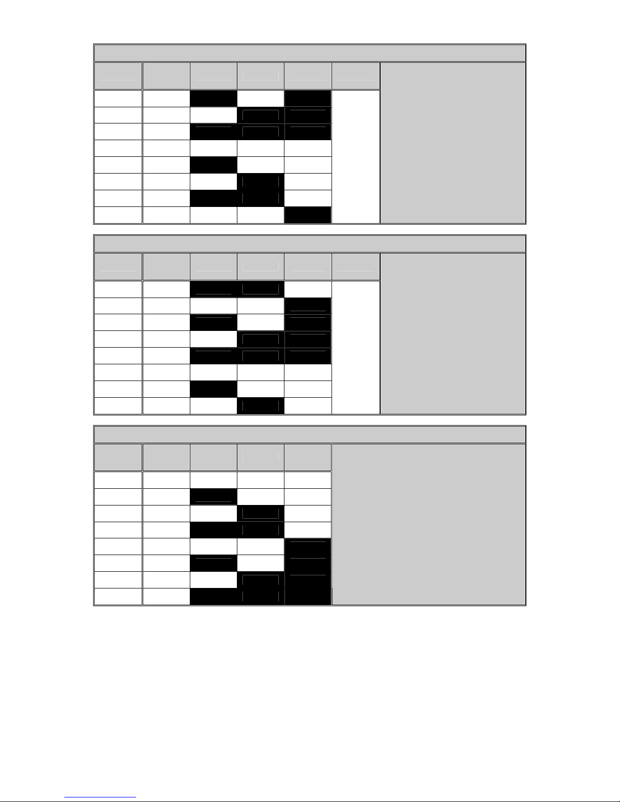
© Hills Industries 2006 Page 58
NX-408E / NX-416E / NX-448E Wireless Receiver Address Settings
Module
Number
Reported
Switch 1 Switch 2 Switch 3 Switch 4
1st 32 ON OFF ON OFF
2nd 33 OFF ON ON OFF
3rd 34 ON ON ON OFF
4th 35 OFF OFF OFF OFF
5th 36 ON OFF OFF OFF
6th 37 OFF ON OFF OFF
7th 38 ON ON OFF OFF
8th 39 OFF OFF ON OFF
NX-507E / NX-508E Relay / Output Expanders
Module
Number
Reported
Switch 1 Switch 2 Switch 3 Switch 4
1st 24 ON ON OFF
2nd 25 OFF OFF ON
3rd 26 ON OFF ON
4th 27 OFF ON ON
5th 28 ON ON ON
6th 29 OFF OFF OFF
7th 30 ON OFF OFF
8th 31 OFF ON OFF
When
set to
OFF
disables
tamper
feature
NX-320 Remote Power Supply
Module
Number
Reported
Switch 1 Switch 2 Switch 3
1st 84 OFF OFF OFF
2nd 85 ON OFF OFF
3rd 86 OFF ON OFF
4th 87 ON ON OFF
5th 88 OFF OFF ON
6th 89 ON OFF ON
7th 90 OFF ON ON
8th 91 ON ON ON
Recommendation
It is highly advised to disconnect all power (incl backup bat tery) from the panel before connecting new expander mod ules,
on power up the control panel will enrol modules. Next enter program mode and default the new module:
[Á] 8 [Program Code] [Module Number] # 9 1 0 # [Exit] [Exit] [Wait 10 seconds] the module is now ready to be
used/programmed.
Page 61
© Hills Industries 2006 Page 59
Appendix 4: Troubleshooting System Problems
Device Problem Remedy
Code Pad
Code pad appears dead - no lights or sounds when keys are pressed.
1. Measure the output voltage at the Aux Pwr (+) terminals. Voltage should be above
12.8 volt dc.
2. Disconnect all devices connected to Aux Pwr (+) terminal le aving only the code pad
connected.
3. Check for short circuits on devices connected to Aux Pwr (+) terminals.
4. Check that AC power and battery are correctly connected to panel.
5.
Check wiring and connections at code pad & panel.
Code pad lights appear OK, but no functions when the keys are pressed.
1. Check the user code you are entering is pro grammed on the system and is an
Arm/Disarm code.
2.
Ensure you have set the code pad No and Area No. That is feature ¹ 94 in section
“Programming the code pad”
Fire LED flashes rapidly.
1. Measure Aux Pwr (+) terminal. Voltage should be above 12.8 Volt DC.
2. Check Data wire is connected correctly at both ends.
3. Smoke detector circuit may have gone into alarm. Press ¹ 7 to reset.
4.
Try connecting code pads one at a time and see if problem is related to a particular
code pad.
After Exiting from program mode code pad will not accept key presses.
1. Wait 12 seconds after leaving program mode before entering key presses at the
code pad.
Unable to write custom messages to multiple LCD code pads on system.
1. Ensure you have individually set the code pad No(s) and Area No(s) for each code
pad. That is feature ¹ 94 in section Programming the Code Pad
2. Enter and then exit program mode.
3.
Enter custom message menu, view any message and then exit. See feature ¹ 92 in
the NX148 LCD Code Pad installation manual.
Zones LED(s) flash rapidly, Arming and Disarming will not clear condition.
1. A zone tamper condition has occurred.
2. Press ¹ 7 to reset condition and clear rapid flashing LED’s.
3.
If the zone is still in tamper the ¹ 7 will only clear the condition temporarily.
Starts beeping and you must enter a code to stop the beeps.
1. There is a system fault present. Press ¹ 2 to see why the system started beeping.
Page 62
© Hills Industries 2006 Page 60
System
Service Light “ON” - Pressing ¹ 2 displays LED 1.
Press the (1) key and observe which LED comes on to indicate one of the
following:
1. Over Current Fault
A Partial short circuit on the Aux Pwr, Smoke power, Horn Speaker, Strobe or
Screamer will cause an over current faults. (Fuseless design)
Removing the short from the Aux Pwr or Smoke Pwr will fix the over current condition
immediately.
If the short is on the horn, Strobe or Screamer you must put the panel into alarm
once the fault has been removed to clear the over current condition.
2. Siren Trouble
The Horn Speaker is open / short circuit or not connected.
The Hills Reliance control panel monitors the siren output for faults and tampering. If
a horn speaker is not connected to the panel place a 3K3 resistor across the Bell
output to disable Siren Trouble Monitoring.
3. Box Tamper
The box tamper pins are open circuit or activated. Ens ure the box tamper pins are
sealed (closed circuit). Arm and Disarm system to clear box tamper condition.
4. Expander Power
An expander connected to the system has a short circuit on the Aux output.
Expander that can report this condition are power supply (NX320).
5. Expander Low Battery
An expansion device connected to the Hills Reliance system has a Low Battery
condition. Expander that can indicate low battery conditions: NX320 power supply.
Replace Battery.
6. Expander Box Tamper
An expansion device connected to the Hills Reliance system has a tamper activated.
Check the tamper contacts on the expansion devices connected. Expanders that can
indicate box tamper: Code pads, Hardwire zone expanders and Wireless zone
expanders.
7. Expander Trouble
Code pads are not number correctly (see ¹ 94 code pad program)
Expander connected is not seen by system. Enter and Exit program mode.
You are trying to zone double a NX4 panel (not supported)
Only the Hills Reliance 8, Reliance 12, and Reliance 128 can be zone doubled.
Any device connected to the data terminal on the Hills Reliance s ystem c an cause an
expander trouble condition.
8. Reserved
System
Service Light “ON” - Pressing ¹ 2 displays LED 2.
Zone Tamper has been activated. Press the (2) key and the zone(s) th at activated
the tamper will be displayed. Press the (#) key twice to exit. Press ¹ 7 is reset
tamper condition.
Service Light “ON” - Pressing ¹ 2 displays LED 3.
Low Battery (wireless zones only). Press the (3) key and the wireless zone(s) with
low battery will be displayed. Press the (#) key twice to exit.
Page 63
© Hills Industries 2006 Page 61
System
Service Light “ON” - Pressing ¹ 2 displays LED 4.
Loss of Supervision (wireless zone only). Press the (4) key and the wireless zone(s)
with Loss of Supervision will be displayed. Press the (#) key twice to exit.
Service Light “ON” - Pressing ¹ 2 displays LED 5.
Zone Trouble. Press the (5) key and the zone that has trou ble will b e disp la yed. Z one
trouble only applies to Fire type zones. Pr ess the (#) key t wice to exit. Pr ess ¹ 7 to
reset zone trouble condition.
Service Light “ON” - Pressing ¹ 2 displays LED 6.
Telephone line trouble/Line cut, when telephone line is cut from panel.
Service Light “ON” - Pressing ¹ 2 displays LED 7.
When light number 7 is lit this indicates that the panel has failed to communicate to
the base station. This led can only be extinguished by communicating to the base.
Check Phone No, Account Code and Format programming.
Press the (#) key twice to exit.
Service Light “ON” - Pressing ¹ 2 displays LED 8.
When light 8 is lit this indicates that the panel has lost time. Press the (#) key twice
to exit.
To set system time:
¹ 97 (go to program code), enter time (4 digits) Eg 10:30am = 1030
Page 64
© Hills Industries 2006 Page 62
Installation Floor Plan
Instructions
1. Sketch the layout of the building using the grid to scale dimensions
2. Identify the position of the control panel, sirens and code pads
3. Identify the location of all detectors and verify device coverage with device specifications
4. Plan models and quantities of hardware on the table be low
Installation Parts List
Device Model / Quantity Device Model / Quantity
Control Panel Code Pads (LED)
Siren (Internal) Code Pads (LCD)
Siren (External) Code Pads (Icon)
Strobe 7 Relay Module
PIRs 8 Output Module
Reed switches 16 Zone Expander
Detector cable Smoke Alarms
Data cable Wireless Receiver
Battery Key Fobs
Power Supply Smart Power Supply
Page 65
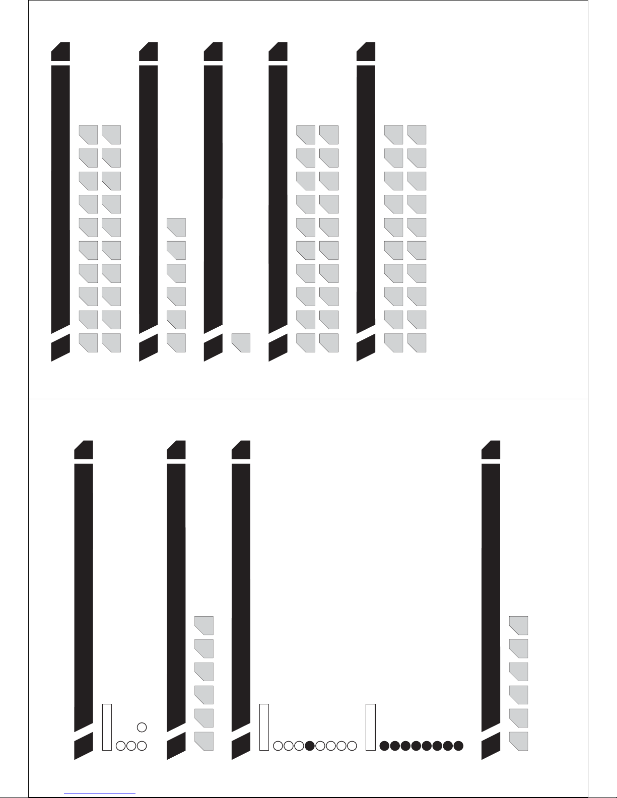
to
Enables 6 digit code. All Arm/Disarm/Go to Program codes require 6 digits
On enables ‘Go To Program Code’ as an Arm Only code
On enables the ‘Go To Program Code’ for area #1
On enables the ‘Go To Program Code’ for area #2
On enables the ‘Go To Program Code’ for area #3
On enables the ‘Go To Program Code’ for area #4
On enables the ‘Go To Program Code’ for area #5
On enables the ‘Go To Program Code’ for area #6
On enables the ‘Go To Program Code’ for area #7
On enables the ‘Go To Program Code’ for area #8
On enables ‘Go To Program Code’ to bypass zones
On enables ‘Go To Program Code’ as an Arm/Disarm code
Reserved
Requires valid user code entry for [*][9][8] and [*][9][9] functions to work
On enables ‘Go To Program Code’ as an Arm Only after closing
On enables ‘Go To Program Code’ opening and closing reports
On enables ‘Go To Program Code’ as a Master code (can change user codes)
Reserved
Reserved
Pg
23
Pg
23
Pg
23
Pg
23
User Code Requirements
Go To Program Code
Go To Program Code Area and Authorisation
Duress Code
0
Feat.
1
Feat.
2
Feat.
3
Feat.
9
15
7
15
1
15
3
15
0
15
0
15
Segment 1
Segment 1
Segment 2
Program Planning Sheets
3
7
1
2
4
685
123
678
5
123 8
4
Pg
24
Pg
24
Pg
25
Pg
24
Pg
24
Phone # 1
Phone # 2
Phone # 3
System Account Code
Communicator Format
4
Feat.
7
Feat.
8
Feat.
5
Feat.
6
Feat.
14
14
14
14
14
14
14
14
14
14
14
14
14
14
14
14
14
14
14
14
14
14
14
14
14
14
14
14
14
14
14
14
14
14
14
14
10
0
14
14
14
14
14
14
10
14
14
14
14
14
14
10
14
14
14
14
14
14
10
14
14
14
14
14
14
10 10
Page 66
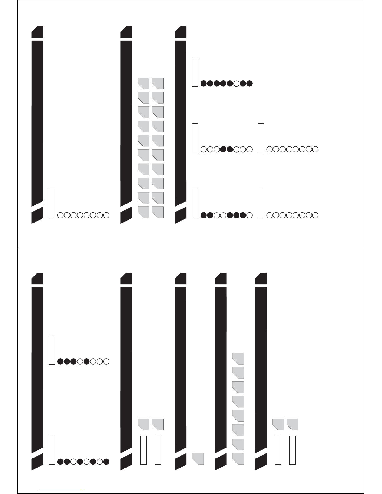
Pg
25
Pg
26
Pg
25
Pg
26
Dial Attempts \ Dialing Options
No. of Rings / Calls to Answer Download
Phone Line Cut Delay
Download Access Code
10
Feat.
13
Feat.
11
Feat.
12
Feat.
6
0
0
0
0
6000000
Dial Attempts
Number of rings
Dialing Options (0 = No function,1=DualReport,4=Extended Phone Number)
Number of calls to answer download
Segment 1
Segment 1
Segment 2
Segment 2
1
Alarms System Trouble (siren, phone, expander, short circuit, earth fault)
Zone Trouble and Restore Cancel Code (also set for each area, Feat 16 - Seg3-Op6)
Bypass and Bypass Restore Program, Download, & Full Log (also set Feat 22 - Seg4-Op2)
Test Reports Reserved
Alarm Restores Failure to Communicate
Power Trouble (AC Failure or Low Battery) and Restore Recent Closing / Exit Error
Opening / Closing (alarm system off = Open, alarm system on = Close) Sensor Lost / Sensor Low Battery
Zone and Box Tampers and Restore Reserved
Pg
25
Event Report Summary
9
Feat.
Segment 1 Segment 2
1
2
4
6
837
3
1
2
4
678
5 5
On enables the Quick Arm option
On enables the Late To Close option
On enables the LED Extinguish option
Reserved
On enables Opening and Closing reports
On enables the Audible Code Pad Panic
Reserved
On enables Bypass toggle
Reserved
On enables Zone Tamper reporting
On enables the Silent Code Pad Panic
On disables Bypass for Force Arm Zones
AC Power/Low Battery Sounder Alert
Reserved
On enables Zone Trouble reporting
Multiple Code Attempt Tamper option
Reserved
Enables One Key Partial Mode Disarming
Reserved
On enables Exit Error option
On enables the Re-exit option
On enables the Autoarm In Partial option
Require User Code for bypassing zones
Reserved
On enables Zone Bypass reporting
On enables the Code Pad Fire option
Reserved
On enables Silent Auto Arm
Reserved
On enables the Cancel option
On enables the Force Arm option
Reserved
Zone Bypassed Sounder Alert option
Reserved
On enables Zone Restore reporting
On enables the Code Pad Medical option
Reserved
On enables the Universal Arming option
Reserved
On enables Recent Closing option
Pg
27
Area 1 - Options and Report Selections
16
Feat.
Segment 2
Segment 5
Segment 3Segment 1
Segment 4
7
1
2
6
5
3
7
1
2
4 4
8
5 5
123
4
678
5
123
4
678
5
Pg
26
Callback Phone Number
15
Feat.
14
14
14
14
14
14
14
14
14
14
14
14
14
14
14
14
14
1414
14
On enables two call Answering Machine Defeat
On locks all local programming (can only be changed through download software)
On enables Control Panel Shutdown (can only be changed through download software)
On enables Call Back at Auto Test Interval
Reserved
On locks out communicator programming (can only be changed through download software)
On requires Call Back before Download Session
On locks out download section (can only be changed through download software)
Pg
26
Download Control
14
Feat.
Segment 1
123
4
678
5
3
4
1
2
3
6
7
8
6
8
Page 67
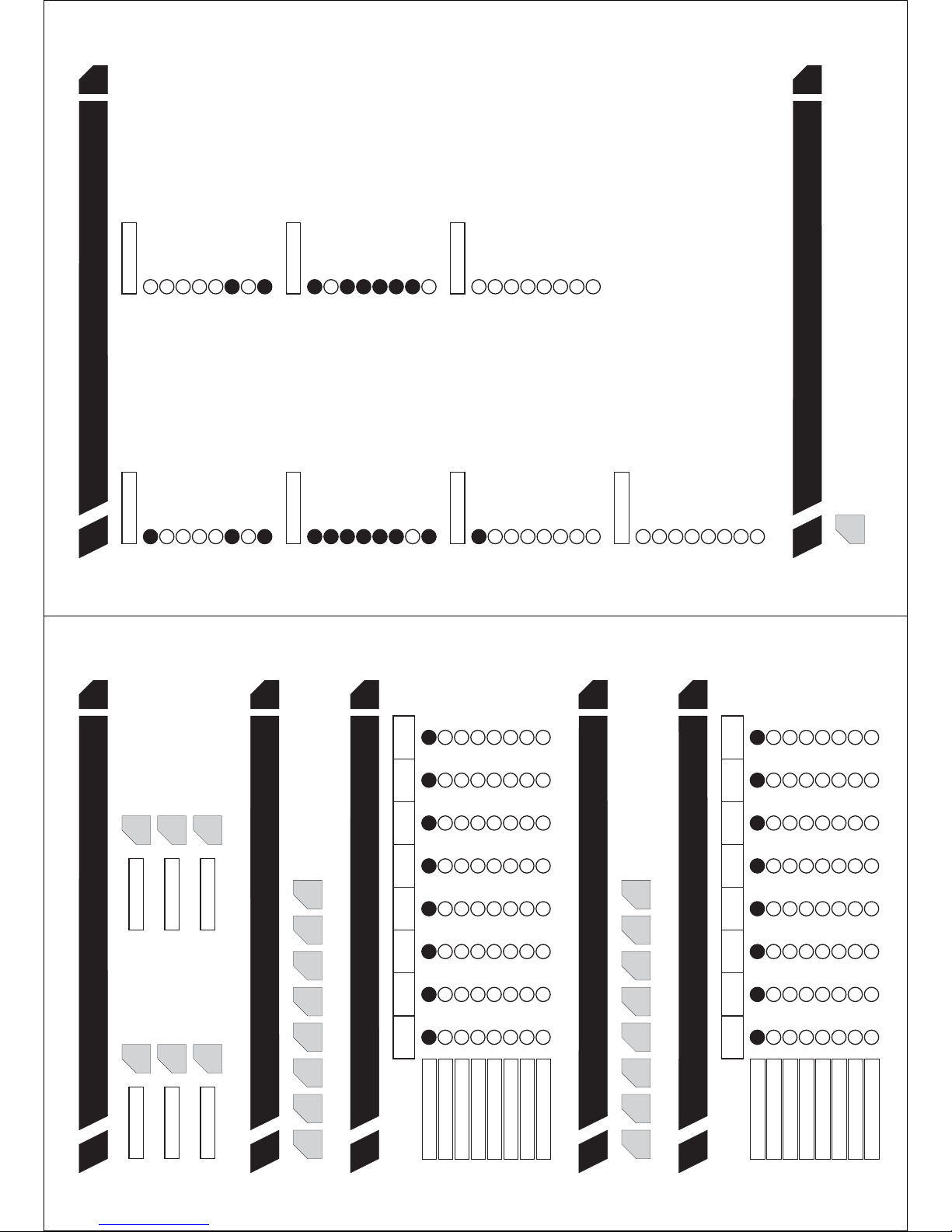
Pg
32
Zone 9-16 Area Selection
21
Feat.
Pg
31
Zone 9-16 Configuration Groups
20
Feat.
16 16
Area 1
Area 2
Area 3
Area 4
Area 5
Area 6
Area 7
Area 8
2 2 2 2 2 2 2 2
3 3 3 3 3 3 3 3
4 4 4 4 4 4 4 4
6 6 6 6 6 6 6 6
7 7 7 7 7 7 7 7
8 8 8 8 8 8 8 8
1 1 1 1 1 1 1 1
5 5 5 5 5 5 5 5
Segment 1
(Zone 9)
Segment 2
(Zone 10)
Segment 3
(Zone 11)
Segment 4
(Zone 12)
Segment 5
(Zone 13)
Segment 6
(Zone 14)
Segment 7
(Zone 15)
Segment 8
(Zone 16)
16 16 16 16 16 16
Pg
31
Zone 1-8 Area Selection
19
Feat.
Area 1
Area 2
Area 3
Area 4
Area 5
Area 6
Area 7
Area 8
2 2 2 2 2 2 2 2
3 3 3 3 3 3 3 3
4 4 4 4 4 4 4 4
6 6 6 6 6 6 6 6
7 7 7 7 7 7 7 7
8 8 8 8 8 8 8 8
1 1 1 1 1 1 1 1
5 5 5 5 5 5 5 5
Segment 1
(Zone 1)
Segment 2
(Zone 2)
Segment 3
(Zone 3)
Segment 4
(Zone 4)
Segment 5
(Zone 5)
Segment 6
(Zone 6)
Segment 7
(Zone 7)
Segment 8
(Zone 8)
Pg
29
Area 1 - Entry / Exit Timers
17
Feat.
30
30
60
60
Entry Timer #1
Entry Timer #2
Exit Timer #1
Exit Timer #2
Segment 1
Segment 3
Segment 2
Segment 4
Pg
29
Zone 1-8 Configuration Groups
18
Feat.
7 1616161616163
Reserved Reserved
Segment 5 Segment 6
Pg
35
Siren / Communicator Attempt Count
Feat.
23
0
On if Box Tamper report enabled
On enable Lost Clock service light
On if Fail To Communicate report enabled
Enable Two Wire Smoke
On if Siren Supervision report enabled
On will prevent force armed zones to report bypass
On if End Download report enabled
Reserved
On if Auxilary Power Over-current report enabled
On will enable all Dual End of Line (DEOL) resistors on all zones
On if Start/End programming report enabled
Reserved
On if Expander Trouble reporting enabled
On will Auto Partial Arm Area 1
On if Expander Module (number) to be reported via the Contact I.D
Reserved
On if AC Fail reporting enabled
On enables Zone Doubling
On if Log Full report enabled
Reserved
On if Telephone Line Cut report enabled
On enables Silent Exit option
On if Sensor Low Battery report enabled
Disable Clean-Me Reports (not used in Australia)
On if Low Battery reporting enabled
On disables all hardwired zones on the NX board
On if Auto-test report enabled
Enable Zone Inactivity Time In Hours
Reserved
Reserved
On if Sensor Missing report enabled
Disable Steady (Temporal) Siren (On enables Evacuation Siren for fire
Segment 3
Segment 5
Segment 4
Segment 6
1
2 2
3 3
4 4
6 677 7
8 8
5 5
3 3
1 1
2
4 4
6 6
5 5
8
1
On if siren sounds for ‘Telephone Line Cut’ when armed On to enable Voltage Output; Off to enable On-board Siren Driver
On if siren blast at closing kiss-off On if Battery Missing Test is performed every 12 seconds
On if siren blast at exit delay expiration On if First to Open Last to Close Reports
Siren blasts 1x for key-switch / wireless arming; 2x for disarming On if Box Tamper Pins on the control panel are enabled
On if siren sounds for ‘Telephone Line Cut’ when disarmed On if sirens should sound on expander trouble
On if siren limited to once per zone On if Strobe flashes for 3s for Key-switch Arm and 6s for Disarm
On if siren blast at arming On if Communicator limited to once per zone
On if siren sounds for a Zone or Box Tamper On if Manual Communicator Test performed during [*]-[44] function
Pg
32
System Options
22
Feat.
Segment 1 Segment 2
1
2 2
3 3
4 4
7 7
5 516 6
8 8
7
8
Reserved
Reserved
Reserved
Reserved
Reserved
Reserved
Reserved
Reserved
Segment 7
123
4
678
5
2
Page 68
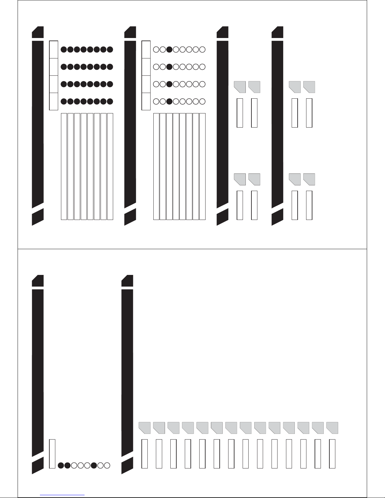
30
5
5
5
0
120
0
0
AC Failure Report Delay (0 -255 min)
Siren Time (1 - 255 min)
Twin Trip Time (0 - 255 min)
Chime Option (‘0’ = Follow, ‘5’ = Chime once, ‘255’ = Latch)
Dialer Delay Time (0 - 255 sec)
Fire Alarm Verification Time (120 – 255 sec)
Reserved
Zone Inactivity Time (days) (see Feature 22, Segment 6, Option 3 to change to hours)
Segment 4
Segment 5
Segment 6
Segment 7
Segment 8
Segment 9
Segment 10
Segment 11
2
Dynamic Battery Test Duration (0 – 255 min)
Segment 3
On if code pad sounds for ‘Telephone Line Cut ‘ when the system is armed
On if code pad sounds during Twin Trip time
On if code pad sounds when a Low Battery is detected
On if code pad sounds for Expander Trouble
On if code pad sounds for ‘Telephone Line Cut‘ when disarmed
On if code pad sounds for Zone and Box Tampers
On if code pad sounds upon AC Power Failure
On if code pad sounds for Medical Alarm
Pg
35
Code Pad Sounder Control
24
Feat.
Segment 1
3
4
7
8
5
1
2
6
20
0
Partial Arm Entry Time (10 - 255 sec)
Strobe Time (0 - 255 hours)
Segment 1
Segment 2
Pg
35
System Timers
25
Feat.
0
Reserved
Segment 12
0
Reserved
Segment 13
0
Reserved
Segment 14
Pg
37
Pg
37
Auxiliary Output 1 - Event & Time
Auxiliary Output 2 - Event & Time
28
Feat.
29
Feat.
5170
0
53530
0
Event A for Aux Out 1
(Default Event 51 = Strobe)
Event A for Aux Out 2
(Default Event 7 = Any Siren)
Event B for Aux Out 1
(Default Event 53 = False)
Event B for Aux Out 2
(Default Event 53 = False)
Logic for Aux Out 1
(Default Logic0=OR)
Logic for Aux Out 2
(Default Logic0=OR)
Timing for Aux Out 1
(Default Timing0=Follow)
Timing for Aux Out 2
(Default Timing 0 = Follow)
Segment 1
Segment 1
Segment 3
Segment 3
Segment 2
Segment 2
Segment 4
Segment 4
Pg
36
Pg
37
Auxiliary Output 1-4 Area Selection
Auxiliary Outputs 1-4 Special Timing
26
Feat.
27
Feat.
On if output should be timed in minutes; Off if timed in seconds
Area 1
Segment 1
(Aux Out 1)
Segment 1
(Aux Out 1)
Segment 2
(Aux Out 2)
Segment 2
(Aux Out 2)
Segment 3
(Aux Out 3)
Segment 3
(Aux Out 3)
Segment 4
(Aux Out 4)
Segment 4
(Aux Out 4)
On if output should latch; Off if output should be timed
Area 2
On if output should stop timing upon code entry; Off if output to follow timer
Area 3
On if output to only activate between the closing and opening time (F33, F34)
Area 4
On if output to only activate between the opening and closing time (F33, F44)
Area 5
On if output inverted (0 volts going to 12 volts when activated)
Area 6
Reserved
Area 7
Reserved
Area 8
1 1 1 1
2 2 2 2
4 4 4 4
6 6 6 6
7 7 7 7
8 8 8 8
5 5 5 5
3 3 3 3
3 3 3 3
7 7 7 7
1 1 1 1
2 2 2 2
4 4 4 4
6 6 6 6
8 8 8 8
5 5 5 5
Page 69
Pg
37
Pg
37
Auxiliary Output 3 - Event & Time
Auxiliary Output 4 - Event & Time
30
Feat.
31
Feat.
23210
0
53530
0
Event A for Aux Out 3
(Default Event 23 = Ready)
Event A for Aux Out 4
(Default Event 21 = Armed)
Event B for Aux Out 3
(Default Event 53 = False)
Event B for Aux Out 4
(Default Event 53 = False)
Logic for Aux Out 3
(Default Logic 0 = OR)
Logic for Aux Out 4
(Default Logic 0 = OR)
Timing for Aux Out 3
(Default Timing 0 = Follow)
Timing for Aux Out 4
(Default Timing 0 = Follow)
Segment 1
Segment 1
Segment 3
Segment 3
Segment 2
Segment 2
Segment 4
Segment 4
0
Auto-test minute
Segment 4
3
Auto-test hour (ignored if Feature 32 - Segment 1 set to 0)
Segment 3
1
168
Auto-test day (0=hourly, 1=Sun, 2=Mon, 3=Tue, 4=Wed, 5=Thur, 6=Fri, 7=Sat, 8=Daily test)
Auto-test hourly test interval (1-255 hours) (Feature 32 - Segment 1 must be set to 0)
Segment 1
Segment 2
Pg
39
Auto-Test Control
32
Feat.
Pg
39
Opening Time / Auto Disarm Time
33
Feat.
8
0
Hours
Minutes
Segment 1
Segment 2
Pg
39
Closing Time / Auto Arm Time
34
Feat.
20
0
Hours
Minutes
Segment 1
Segment 2
Segment 1
(Area 1)
Segment 2
(Area 2)
Segment 3
(Area 3)
Segment 4
(Area 4)
Segment 5
(Area 5)
Segment 6
(Area 6)
Segment 7
(Area 7)
Segment 8
(Area 8)
SunSunSunSunSunSunSun
ThurThurThurThurThurThurThur
WedWedWedWedWedWedWed
ReservedReservedReservedReservedReservedReservedReserved
MonMonMonMonMonMonMon
FriFriFriFriFriFriFri
TueTueTueTueTueTueTue
SatSatSatSatSatSatSat
Pg
39
Days Open / ‘Arm Only After Close’ Window Authority
35
Feat.
Pg
40
Days of the Week for Auto Arm Areas 1-8
36
Feat.
10 10
10
10
10
10
Pg
40
Area 1 Account Code
37
Feat.
Sun Sun Sun Sun Sun Sun Sun Sun
Thur Thur Thur Thur Thur Thur Thur Thur
WedWedWedWedWedWedWedWed
Reserved Reserved Reserved Reserved Reserved Reserved Reserved Reserved
Mon Mon Mon Mon Mon Mon Mon Mon
Fri Fri Fri Fri Fri Fri Fri Fri
Tue Tu e Tu e Tu e Tue Tue Tue Tue
Sat Sat Sat Sat Sat Sat Sat Sat
3 3 3 3 3 3 3 3
7 7 7 7 7 7 7 7
1 1 1 1 1 1 1 1
2 2 2 2 2 2 2 2
4 4 4 4 4 4 4 4
5 5 5 5 5 5 5 5
8 8 8 8 8 8 8 8
6 6 6 6 6 6 6 6
1111111
3333333
6666666
5555555
8888888
4444444
7777777
2222222
Sun
Thur
Wed
Reserved
Mon
Fri
Tue
Sat
1
36584
7
2
Segment 1
(Area 1)
Segment 2
(Area 2)
Segment 3
(Area 3)
Segment 4
(Area 4)
Segment 5
(Area 5)
Segment 6
(Area 6)
Segment 7
(Area 7)
Segment 8
(Area 8)
Page 70
On enables the Quick Arm option
On enables the Late To Close option
On enables the LED Extinguish option
Reserved
On enables Opening and Closing reports
On enables the Audible Code Pad Panic
Reserved
On enables Bypass toggle
Reserved
On enables Zone Tamper reporting
On enables the Silent Code Pad Panic
On disables Bypass for Force Arm Zones
AC Power/Low Battery Sounder Alert
Reserved
On enables Zone Trouble reporting
Multiple Code Attempt Tamper option
Reserved
Enables One Key Partial Mode Disarming
Reserved
On enables Exit Error option
On enables the Re-exit option
On enables the Autoarm In Partial option
Require User Code for bypassing zones
Reserved
On enables Zone Bypass reporting
On enables the Code Pad Fire option
Reserved
On enables Silent Auto Arm
Reserved
On enables the Cancel option
On enables the Force Arm option
Reserved
Zone Bypassed Sounder Alert option
Reserved
On enables Zone Restore reporting
On enables the Code Pad Medical option
Reserved
On enables the Universal Arming option
Reserved
On enables Recent Closing option
Pg
41
Area 2 - Options and Report Selections
39
Feat.
Segment 2
Segment 5
Segment 3Segment 1
Segment 4
123
4
678
5
123
4
678
5
1 1 1
2 2 2
3 3 3
4 4 4
6 6 6
7 7 7
8 8 8
5 5 5
Pg
42
Area 2 - Entry / Exit Timers
40
Feat.
30
30
60
60
Entry Timer #1
Entry Timer #2
Exit Timer #1
Exit Timer #2
Segment 1
Segment 3
Segment 2
Segment 4
00
Reserved Reserved
Segment 5 Segment 6
10 10
10
10
10
10
Pg
40
Area 2 - Account Code
38
Feat.
On enables the Quick Arm option
On enables the Late To Close option
On enables the LED Extinguish option
Reserved
On enables Opening and Closing reports
On enables the Audible Code Pad Panic
Reserved
On enables Bypass toggle
Reserved
On enables Zone Tamper reporting
On enables the Silent Code Pad Panic
On disables Bypass for Force Arm Zones
AC Power/Low Battery Sounder Alert
Reserved
On enables Zone Trouble reporting
Multiple Code Attempt Tamper option
Reserved
Enables One Key Partial Mode Disarming
Reserved
On enables Exit Error option
On enables the Re-exit option
On enables the Autoarm In Partial option
Require User Code for bypassing zones
Reserved
On enables Zone Bypass reporting
On enables the Code Pad Fire option
Reserved
On enables Silent Auto Arm
Reserved
On enables the Cancel option
On enables the Force Arm option
Reserved
Zone Bypassed Sounder Alert option
Reserved
On enables Zone Restore reporting
On enables the Code Pad Medical option
Reserved
On enables the Universal Arming option
Reserved
On enables Recent Closing option
Pg
42
Area 3 - Options and Report Selections
42
Feat.
Segment 2
Segment 5
Segment 3Segment 1
Segment 4
123
4
678
5
123
4
678
5
1 1 1
2 2 2
3 3 3
4 4 4
6 6 6
7 7 7
8 8 8
5 5 5
Pg
42
Area 3 - Entry / Exit Timers
43
Feat.
30
30
60
60
Entry Timer #1
Entry Timer #2
Exit Timer #1
Exit Timer #2
Segment 1
Segment 3
Segment 2
Segment 4
00
Reserved Reserved
Segment 5 Segment 6
10 10
10
10
10
10
Pg
42
Area 3 - Account Code
41
Feat.
Page 71
On enables the Quick Arm option
On enables the Late To Close option
On enables the LED Extinguish option
Reserved
On enables Opening and Closing reports
On enables the Audible Code Pad Panic
Reserved
On enables Bypass toggle
Reserved
On enables Zone Tamper reporting
On enables the Silent Code Pad Panic
On disables Bypass for Force Arm Zones
AC Power/Low Battery Sounder Alert
Reserved
On enables Zone Trouble reporting
Multiple Code Attempt Tamper option
Reserved
Enables One Key Partial Mode Disarming
Reserved
On enables Exit Error option
On enables the Re-exit option
On enables the Autoarm In Partial option
Require User Code for bypassing zones
Reserved
On enables Zone Bypass reporting
On enables the Code Pad Fire option
Reserved
On enables Silent Auto Arm
Reserved
On enables the Cancel option
On enables the Force Arm option
Reserved
Zone Bypassed Sounder Alert option
Reserved
On enables Zone Restore reporting
On enables the Code Pad Medical option
Reserved
On enables the Universal Arming option
Reserved
On enables Recent Closing option
Pg
42
Area 4 - Options and Report Selections
45
Feat.
Segment 2
Segment 5
Segment 3Segment 1
Segment 4
123
4
678
5
123
4
678
5
1 1 1
2 2 2
3 3 3
4 4 4
6 6 6
7 7 7
8 8 8
5 5 5
Pg
42
Area 4 - Entry / Exit Timers
46
Feat.
30
30
60
60
Entry Timer #1
Entry Timer #2
Exit Timer #1
Exit Timer #2
Segment 1
Segment 3
Segment 2
Segment 4
00
Reserved Reserved
Segment 5 Segment 6
10 10
10
10
10
10
Pg
42
Area 4 - Account Code
44
Feat.
On enables the Quick Arm option
On enables the Late To Close option
On enables the LED Extinguish option
Reserved
On enables Opening and Closing reports
On enables the Audible Code Pad Panic
Reserved
On enables Bypass toggle
Reserved
On enables Zone Tamper reporting
On enables the Silent Code Pad Panic
On disables Bypass for Force Arm Zones
AC Power/Low Battery Sounder Alert
Reserved
On enables Zone Trouble reporting
Multiple Code Attempt Tamper option
Reserved
Enables One Key Partial Mode Disarming
Reserved
On enables Exit Error option
On enables the Re-exit option
On enables the Autoarm In Partial option
Require User Code for bypassing zones
Reserved
On enables Zone Bypass reporting
On enables the Code Pad Fire option
Reserved
On enables Silent Auto Arm
Reserved
On enables the Cancel option
On enables the Force Arm option
Reserved
Zone Bypassed Sounder Alert option
Reserved
On enables Zone Restore reporting
On enables the Code Pad Medical option
Reserved
On enables the Universal Arming option
Reserved
On enables Recent Closing option
Pg
43
Area 5 - Options and Report Selections
48
Feat.
Segment 2
Segment 5
Segment 3Segment 1
Segment 4
123
4
678
5
123
4
678
5
1 1 1
2 2 2
3 3 3
4 4 4
6 6 6
7 7 7
8 8 8
5 5 5
Pg
43
Area 5 - Entry / Exit Timers
49
Feat.
30
30
60
60
Entry Timer #1
Entry Timer #2
Exit Timer #1
Exit Timer #2
Segment 1
Segment 3
Segment 2
Segment 4
00
Reserved Reserved
Segment 5 Segment 6
10 10
10
10
10
10
Pg
42
Area 5 - Account Code
47
Feat.
Page 72
On enables the Quick Arm option
On enables the Late To Close option
On enables the LED Extinguish option
Reserved
On enables Opening and Closing reports
On enables the Audible Code Pad Panic
Reserved
On enables Bypass toggle
Reserved
On enables Zone Tamper reporting
On enables the Silent Code Pad Panic
On disables Bypass for Force Arm Zones
AC Power/Low Battery Sounder Alert
Reserved
On enables Zone Trouble reporting
Multiple Code Attempt Tamper option
Reserved
Enables One Key Partial Mode Disarming
Reserved
On enables Exit Error option
On enables the Re-exit option
On enables the Autoarm In Partial option
Require User Code for bypassing zones
Reserved
On enables Zone Bypass reporting
On enables the Code Pad Fire option
Reserved
On enables Silent Auto Arm
Reserved
On enables the Cancel option
On enables the Force Arm option
Reserved
Zone Bypassed Sounder Alert option
Reserved
On enables Zone Restore reporting
On enables the Code Pad Medical option
Reserved
On enables the Universal Arming option
Reserved
On enables Recent Closing option
Pg
43
Area 6 - Options and Report Selections
51
Feat.
Segment 2
Segment 5
Segment 3Segment 1
Segment 4
123
4
678
5
123
4
678
5
1 1 1
2 2 2
3 3 3
4 4 4
6 6 6
7 7 7
8 8 8
5 5 5
Pg
43
Area 6 - Entry / Exit Timers
52
Feat.
30
30
60
60
Entry Timer #1
Entry Timer #2
Exit Timer #1
Exit Timer #2
Segment 1
Segment 3
Segment 2
Segment 4
00
Reserved Reserved
Segment 5 Segment 6
10 10
10
10
10
10
Pg
43
Area 6 - Account Code
50
Feat.
On enables the Quick Arm option
On enables the Late To Close option
On enables the LED Extinguish option
Reserved
On enables Opening and Closing reports
On enables the Audible Code Pad Panic
Reserved
On enables Bypass toggle
Reserved
On enables Zone Tamper reporting
On enables the Silent Code Pad Panic
On disables Bypass for Force Arm Zones
AC Power/Low Battery Sounder Alert
Reserved
On enables Zone Trouble reporting
Multiple Code Attempt Tamper option
Reserved
Enables One Key Partial Mode Disarming
Reserved
On enables Exit Error option
On enables the Re-exit option
On enables the Autoarm In Partial option
Require User Code for bypassing zones
Reserved
On enables Zone Bypass reporting
On enables the Code Pad Fire option
Reserved
On enables Silent Auto Arm
Reserved
On enables the Cancel option
On enables the Force Arm option
Reserved
Zone Bypassed Sounder Alert option
Reserved
On enables Zone Restore reporting
On enables the Code Pad Medical option
Reserved
On enables the Universal Arming option
Reserved
On enables Recent Closing option
Pg
43
Area 7 - Options and Report Selections
54
Feat.
Segment 2
Segment 5
Segment 3Segment 1
Segment 4
123
4
678
5
123
4
678
5
1 1 1
2 2 2
3 3 3
4 4 4
6 6 6
7 7 7
8 8 8
5 5 5
Pg
43
Area 7 - Entry / Exit Timers
55
Feat.
30
30
60
60
Entry Timer #1
Entry Timer #2
Exit Timer #1
Exit Timer #2
Segment 1
Segment 3
Segment 2
Segment 4
00
Reserved Reserved
Segment 5 Segment 6
10 10
10
10
10
10
Pg
43
Area 7 - Account Code
53
Feat.
Page 73
On enables the Quick Arm option
On enables the Late To Close option
On enables the LED Extinguish option
Reserved
On enables Opening and Closing reports
On enables the Audible Code Pad Panic
Reserved
On enables Bypass toggle
Reserved
On enables Zone Tamper reporting
On enables the Silent Code Pad Panic
On disables Bypass for Force Arm Zones
AC Power/Low Battery Sounder Alert
Reserved
On enables Zone Trouble reporting
Multiple Code Attempt Tamper option
Reserved
Enables One Key Partial Mode Disarming
Reserved
On enables Exit Error option
On enables the Re-exit option
On enables the Autoarm In Partial option
Require User Code for bypassing zones
Reserved
On enables Zone Bypass reporting
On enables the Code Pad Fire option
Reserved
On enables Silent Auto Arm
Reserved
On enables the Cancel option
On enables the Force Arm option
Reserved
Zone Bypassed Sounder Alert option
Reserved
On enables Zone Restore reporting
On enables the Code Pad Medical option
Reserved
On enables the Universal Arming option
Reserved
On enables Recent Closing option
Pg
44
Area 8 - Options and Report Selections
57
Feat.
Segment 2
Segment 5
Segment 3Segment 1
Segment 4
123
4
678
5
123
4
678
5
1 1 1
2 2 2
3 3 3
4 4 4
6 6 6
7 7 7
8 8 8
5 5 5
Pg
44
Area 8 - Entry / Exit Timers
58
Feat.
30
30
60
60
Entry Timer #1
Entry Timer #2
Exit Timer #1
Exit Timer #2
Segment 1
Segment 3
Segment 2
Segment 4
00
Reserved Reserved
Segment 5 Segment 6
10 10
10
10
10
10
Pg
44
Area 8 - Account Code
56
Feat.
Pg
45
Zone 25-32 Area Selection
62
Feat.
Pg
44
Zone 25-32 Configuration Groups
61
Feat.
16 16
Area 1
Area 2
Area 3
Area 4
Area 5
Area 6
Area 7
Area 8
2 2 2 2 2 2 2 2
3 3 3 3 3 3 3 3
4 4 4 4 4 4 4 4
6 6 6 6 6 6 6 6
7 7 7 7 7 7 7 7
8 8 8 8 8 8 8 8
1 1 1 1 1 1 1 1
5 5 5 5 5 5 5 5
Segment 1
(Zone 25)
Segment 2
(Zone 26)
Segment 3
(Zone 27)
Segment 4
(Zone 28)
Segment 5
(Zone 29)
Segment 6
(Zone 30)
Segment 7
(Zone 31)
Segment 8
(Zone 32)
16 16 16 16 16 16
Pg
44
Zone 17-24 Area Selection
60
Feat.
Area 1
Area 2
Area 3
Area 4
Area 5
Area 6
Area 7
Area 8
2 2 2 2 2 2 2 2
3 3 3 3 3 3 3 3
4 4 4 4 4 4 4 4
6 6 6 6 6 6 6 6
7 7 7 7 7 7 7 7
8 8 8 8 8 8 8 8
1 1 1 1 1 1 1 1
5 5 5 5 5 5 5 5
Segment 1
(Zone 17)
Segment 2
(Zone 18)
Segment 3
(Zone 19)
Segment 4
(Zone 20)
Segment 5
(Zone 21)
Segment 6
(Zone 22)
Segment 7
(Zone 23)
Segment 8
(Zone 24)
Pg
44
Zone 17-24 Configuration Groups
59
Feat.
16 16 16 16 16 16 1616
Page 74
Pg
45
Zone 41-48 Area Selection
66
Feat.
Pg
45
Zone 41-48 Configuration Groups
65
Feat.
16 16
Area 1
Area 2
Area 3
Area 4
Area 5
Area 6
Area 7
Area 8
2 2 2 2 2 2 2 2
3 3 3 3 3 3 3 3
4 4 4 4 4 4 4 4
6 6 6 6 6 6 6 6
7 7 7 7 7 7 7 7
8 8 8 8 8 8 8 8
1 1 1 1 1 1 1 1
5 5 5 5 5 5 5 5
Segment 1
(Zone 41)
Segment 2
(Zone 42)
Segment 3
(Zone 43)
Segment 4
(Zone 44)
Segment 5
(Zone 45)
Segment 6
(Zone 46)
Segment 7
(Zone 47)
Segment 8
(Zone 48)
16 16 16 16 16 16
Pg
45
Zone 33-40 Area Selection
64
Feat.
Area 1
Area 2
Area 3
Area 4
Area 5
Area 6
Area 7
Area 8
2 2 2 2 2 2 2 2
3 3 3 3 3 3 3 3
4 4 4 4 4 4 4 4
6 6 6 6 6 6 6 6
7 7 7 7 7 7 7 7
8 8 8 8 8 8 8 8
1 1 1 1 1 1 1 1
5 5 5 5 5 5 5 5
Segment 1
(Zone 33)
Segment 2
(Zone 34)
Segment 3
(Zone 35)
Segment 4
(Zone 36)
Segment 5
(Zone 37)
Segment 6
(Zone 38)
Segment 7
(Zone 39)
Segment 8
(Zone 40)
Pg
45
Zone 33-40 Configuration Groups
63
Feat.
16 16 16 16 16 16 1616
Pg
45
Configuration Group 1 - Alarm Event Code
67
Feat.
3
Fire (turn on if this is a fire zone)
Reserved
Reserved
On if configuration group will beep the code pad for alarm
Zone Activity Monitor
Delay 1 zone (follows timer 1 entry and exit times)
On enables Dialer Delay zone
Reserved
On if configuration group can be bypassed
Reserved
Follower (turn on for burglary zones that are instant during non-entry
On if configuration group is a Twin Trip Zone
Reserved
On if configuration group will chime
Access Control
Local only (turn on if this zone should not be reported)
Reserved
Reserved
On if configuration group is Active in Partial Mode
Reserved
24 hour (turn on for non-fire 24 hour zones)
On enables Double End of Line Tamper zone
Reserved
On if configuration group will sound the yelping siren for alarm
EOL Resistor Defeat (if enables, a short = seal, open circuit = unseal)
Delay 2 zone (follows timer 2 entry and exit times)
On if configuration group will siren / communicator attempt count
Reserved
On if configuration group is included in the Group Bypass
Reserved
Key-switch zone (normally open switch)
On enables Trouble Reporting zone (Day zone & Fire zones)
Reserved
On if configuration group will sound the steady (temporal) siren for
Request to Exit (REX button)
Reserved
On enables Restore reporting
Reserved
On if configuration group is Force Arm
Reserved
Pg
46
Configuration Group 1 - Characteristic Select
68
Feat.
Segment 1
Segment 3
Segment 5
Segment 2
Segment 4
413
4
5
123
678
4
5
123
678
413
6
4
123
678
5 5
2
8
7
72685
Page 75
Pg
47
Configuration Group 3 - Alarm Event Code
71
Feat.
3
Pg
47
Configuration Group 2 - Characteristic Select
70
Feat.
Segment 1 Segment 2
1
3
6
4
123
678
5 5
2
7
Segment 3 Segment 5Segment 4
413
4
5
123
678
4
5
123
678
72685
Fire
Delay 1
Follower
Local only
24 hour
Delay 2
Key-switch
Reserved
Code pad beep
Bypass
Chime
Partial Mode
Yelping siren
Group Bypass
Steady siren
Force Arm
Reserved
Dialer Delay
Twin Trip
Reserved
DEOL Tamper
Siren / Comm
Trouble
Restore
Zone Activity
Reserved
Access Control
Reserved
Resistor Defeat
Reserved
Request to Exit
Reserved
Reserved
Reserved
Reserved
Reserved
Reserved
Reserved
Reserved
Reserved
Pg
47
Configuration Group 3 - Characteristic Select
72
Feat.
Segment 1 Segment 2
1
3
6
4
123
678
5 5
2
8
7
Segment 3 Segment 5Segment 4
413
4
5
123
678
4
5
123
678
72685
Fire
Delay 1
Follower
Local only
24 hour
Delay 2
Key-switch
Reserved
Code pad beep
Bypass
Chime
Partial Mode
Yelping siren
Group Bypass
Steady siren
Force Arm
Reserved
Dialer Delay
Twin Trip
Reserved
DEOL Tamper
Siren / Comm
Trouble
Restore
Zone Activity
Reserved
Access Control
Reserved
Resistor Defeat
Reserved
Request to Exit
Reserved
Reserved
Reserved
Reserved
Reserved
Reserved
Reserved
Reserved
Reserved
4
8
4
Pg
47
Configuration Group 2 - Alarm Event Code
69
Feat.
3
Pg
47
Configuration Group 5 - Alarm Event Code
75
Feat.
3
Pg
47
Configuration Group 5 - Characteristic Select
76
Feat.
Segment 1 Segment 2
1
3
6
4
123
7
8
5
2
8
7
Segment 3 Segment 5Segment 4
413
4
5
123
678
4
5
123
678
72685
Fire
Delay 1
Follower
Local only
24 hour
Delay 2
Key-switch
Reserved
Code pad beep
Bypass
Chime
Partial Mode
Yelping siren
Group Bypass
Steady siren
Force Arm
Reserved
Dialer Delay
Twin Trip
Reserved
DEOL Tamper
Siren / Comm
Trouble
Restore
Zone Activity
Reserved
Access Control
Reserved
Resistor Defeat
Reserved
Request to Exit
Reserved
Reserved
Reserved
Reserved
Reserved
Reserved
Reserved
Reserved
Reserved
4
6
5
Pg
47
Configuration Group 4 - Characteristic Select
74
Feat.
Segment 1 Segment 2
1
3
123
2
Segment 3 Segment 5Segment 4
1
3
123
123
2
Fire
24 hour
Key-switch
Code pad beep
Yelping siren
Steady siren
Reserved
DEOL Tamper
Trouble
Zone Activity
Resistor Defeat
Request to Exit
Reserved
Reserved
Reserved
Pg
47
Configuration Group 4 - Alarm Event Code
73
Feat.
3
4
6
4
7
8
587
4 4
567
8
45678
768
5
Delay 1
Follower
Local only
Delay 2
Reserved
Bypass
Chime
Partial Mode
Group Bypass
Force Arm
Dialer Delay
Twin Trip
Reserved
Siren / Comm
Restore
Reserved
Access Control
Reserved
Reserved
Reserved
Reserved
Reserved
Reserved
Reserved
Reserved
6
5
Page 76
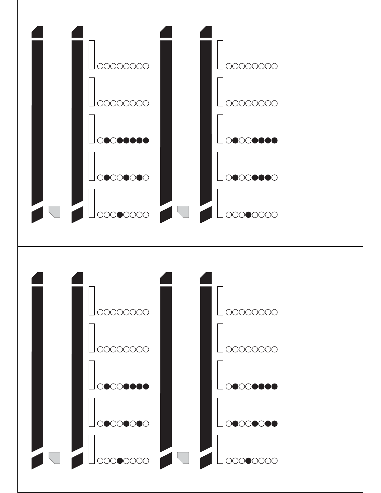
Pg
48
Configuration Group 7 - Characteristic Select
80
Feat.
Segment 1 Segment 2
1
3
6
123
678
527
Segment 3 Segment 5Segment 4
413
4
5
123
678
4
5
123
678
72685
Fire
Delay 1
Follower
Local only
24 hour
Delay 2
Key-switch
Reserved
Code pad beep
Bypass
Chime
Partial Mode
Yelping siren
Group Bypass
Steady siren
Force Arm
Reserved
Dialer Delay
Twin Trip
Reserved
DEOL Tamper
Siren / Comm
Trouble
Restore
Zone Activity
Reserved
Access Control
Reserved
Resistor Defeat
Reserved
Request to Exit
Reserved
Reserved
Reserved
Reserved
Reserved
Reserved
Reserved
Reserved
Reserved
4
5
8
4
3
Pg
48
Configuration Group 7 - Alarm Event Code
79
Feat.
8 888
Local only Partial Mode Reserved Reserved Reserved
8
7 7 777
Reserved ForceArm Restore
Reserved
Reserved
6 666
Delay 2 Group Bypass Siren / Comm
Reserved
Reserved
6
5 555
Delay 1 Bypass Dialer Delay
Reserved
Reserved
5
4 4 44
Follower Chime Twin Trip
Access Control
Reserved
4
33 3 33
Key-switch Steady siren Trouble
Request to Exit
Reserved
2 2 222
24 hour Yelping siren DEOL Tamper
Resistor Defeat
Reserved
11 1 11
Fire Code pad beep Reserved Zone Activity Reserved
Segment 1 Segment 2 Segment 3 Segment 5Segment 4
Pg
48
Configuration Group 6 - Characteristic Select
78
Feat.
3
Pg
47
Configuration Group 6 - Alarm Event Code
77
Feat.
Pg
48
Configuration Group 8 - Alarm Event Code
81
Feat.
3
Pg
48
Configuration Group 8 - Characteristic Select
82
Feat.
Segment 1 Segment 2
11
Segment 3 Segment 5Segment 4
1 11
Fire Code pad beep Reserved Zone Activity Reserved
8 888
Local only Partial Mode Reserved Reserved Reserved
8
Pg
48
Configuration Group 9 - Characteristic Select
84
Feat.
Segment 1 Segment 2
413
123
7
527
Segment 3 Segment 5Segment 4
413
4
5
123
6
7
4
5
123
6
77
2
6
5
Fire
Delay 1
Follower
24 hour
Delay 2
Key-switch
Reserved
Code pad beep
Bypass
Chime
Yelping siren
Group Bypass
Steady siren
Force Arm
Reserved
Dialer Delay
Twin Trip
DEOL Tamper
Siren / Comm
Trouble
Restore
Zone Activity
Reserved
Access Control
Resistor Defeat
Reserved
Request to Exit
Reserved
Reserved
Reserved
Reserved
Reserved
Reserved
Reserved
Reserved
Pg
48
Configuration Group 9 - Alarm Event Code
83
Feat.
3
3
6
2
3
678
527
3
4
5
2
3
678
4
5
2
3
678
72685
Delay 1
Follower
Local only
24 hour
Delay 2
Key-switch
Reserved
Bypass
Chime
Partial Mode
Yelping siren
Group Bypass
Steady siren
Force Arm
Dialer Delay
Twin Trip
Reserved
DEOL Tamper
Siren / Comm
Trouble
Restore
Reserved
Access Control
Reserved
Resistor Defeat
Reserved
Request to Exit
Reserved
Reserved
Reserved
Reserved
Reserved
Reserved
Reserved
Reserved
5
4
5
44
8
4
6 6
Page 77
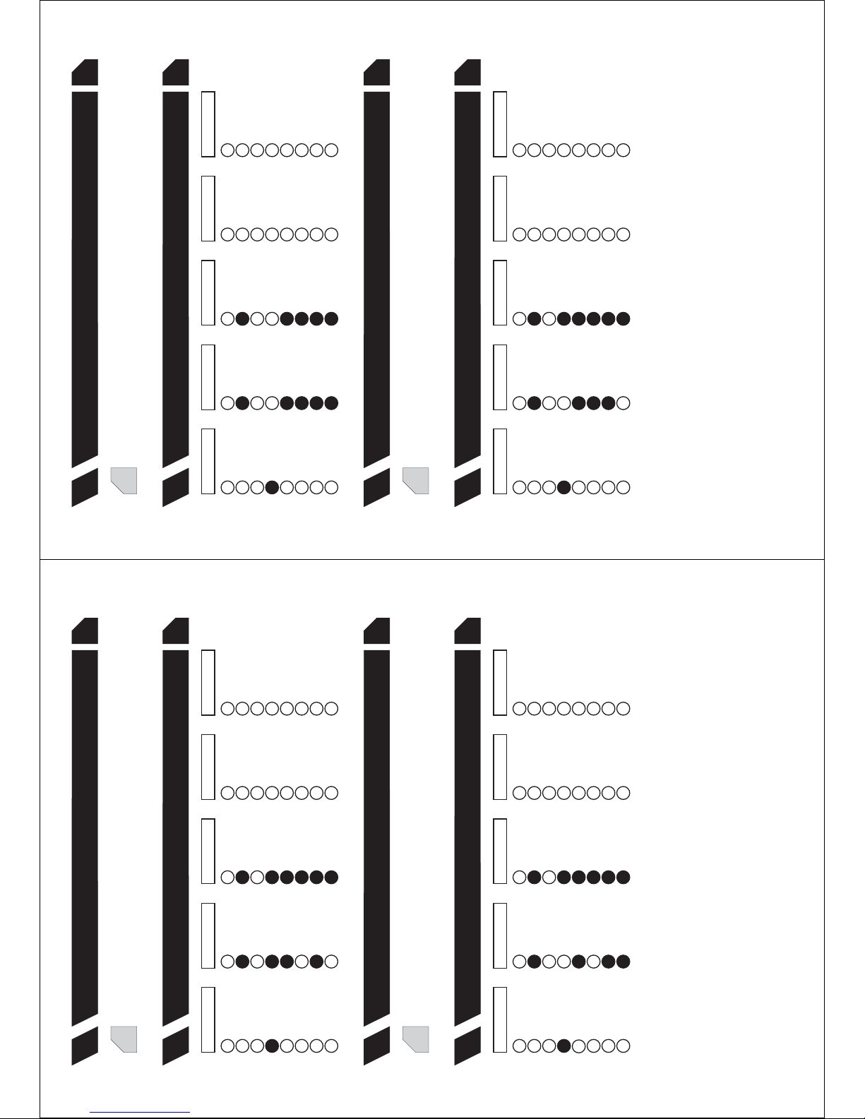
Pg
48
Configuration Group 10 - Alarm Event Code
85
Feat.
3
Pg
49
Configuration Group 11 - Characteristic Select
88
Feat.
Segment 1 Segment 2
413
6
123
7
8
527
Segment 3 Segment 5Segment 4
1
3
4
5
123
678
4
5
123
678
72685
Fire
Delay 1
Follower
Local only
24 hour
Delay 2
Key-switch
Reserved
Code pad beep
Bypass
Chime
Partial Mode
Yelping siren
Group Bypass
Steady siren
Force Arm
Reserved
Dialer Delay
Twin Trip
Reserved
DEOL Tamper
Siren / Comm
Trouble
Restore
Zone Activity
Reserved
Access Control
Reserved
Resistor Defeat
Reserved
Request to Exit
Reserved
Reserved
Reserved
Reserved
Reserved
Reserved
Reserved
Reserved
Reserved
Pg
49
Configuration Group 11 - Alarm Event Code
87
Feat.
3
Pg
48
Configuration Group 10 - Characteristic Select
86
Feat.
Segment 1 Segment 2
1
3
6
123
7
8
527
Segment 3 Segment 5Segment 4
1
3
4
5
123
678
4
5
123
678
72685
Fire
Delay 1
Follower
Local only
24 hour
Delay 2
Key-switch
Reserved
Code pad beep
Bypass
Chime
Partial Mode
Yelping siren
Group Bypass
Steady siren
Force Arm
Reserved
Dialer Delay
Twin Trip
Reserved
DEOL Tamper
Siren / Comm
Trouble
Restore
Zone Activity
Reserved
Access Control
Reserved
Resistor Defeat
Reserved
Request to Exit
Reserved
Reserved
Reserved
Reserved
Reserved
Reserved
Reserved
Reserved
Reserved
4
5
5
4
6
6
4
8
4
4
8
Pg
49
Configuration Group 13 - Alarm Event Code
91
Feat.
3
Pg
49
Configuration Group 12 - Characteristic Select
90
Feat.
Segment 1 Segment 2
1
3
123
678
527
Segment 3 Segment 5Segment 4
413
4
5
123
678
4
5
123
678
72685
Fire
Delay 1
Follower
Local only
24 hour
Delay 2
Key-switch
Reserved
Code pad beep
Bypass
Chime
Partial Mode
Yelping siren
Group Bypass
Steady siren
Force Arm
Reserved
Dialer Delay
Twin Trip
Reserved
DEOL Tamper
Siren / Comm
Trouble
Restore
Zone Activity
Reserved
Access Control
Reserved
Resistor Defeat
Reserved
Request to Exit
Reserved
Reserved
Reserved
Reserved
Reserved
Reserved
Reserved
Reserved
Reserved
Pg
49
Configuration Group 13 - Characteristic Select
92
Feat.
Segment 1 Segment 2
1
3
123
678
527
Segment 3 Segment 5Segment 4
1
3
4
5
123
678
4
5
123
678
72685
Fire
Delay 1
Follower
Local only
24 hour
Delay 2
Key-switch
Reserved
Code pad beep
Bypass
Chime
Partial Mode
Yelping siren
Group Bypass
Steady siren
Force Arm
Reserved
Dialer Delay
Twin Trip
Reserved
DEOL Tamper
Siren / Comm
Trouble
Restore
Zone Activity
Reserved
Access Control
Reserved
Resistor Defeat
Reserved
Request to Exit
Reserved
Reserved
Reserved
Reserved
Reserved
Reserved
Reserved
Reserved
Reserved
4
5
4
4
5
44
8
8
6
6
Pg
49
Configuration Group 12 - Alarm Event Code
89
Feat.
3
Page 78
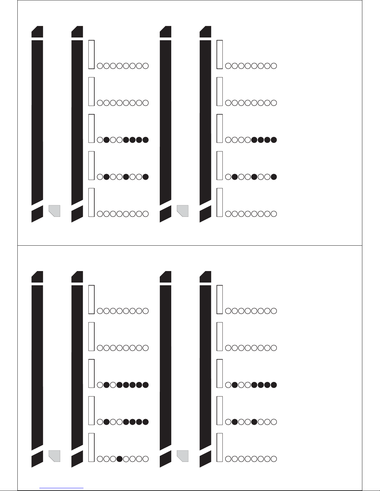
Pg
49
Configuration Group 15 - Alarm Event Code
95
Feat.
3
Pg
50
Configuration Group 15 - Characteristic Select
96
Feat.
Segment 1 Segment 2
1
3
6
123
7
8
5
2
Segment 3 Segment 5Segment 4
1
3
4
5
123
678
4
5
123
678
72685
Fire
Delay 1
Follower
Local only
24 hour
Delay 2
Key-switch
Reserved
Code pad beep
Bypass
Chime
Partial Mode
Yelping siren
Group Bypass
Steady siren
Force Arm
Reserved
Dialer Delay
Twin Trip
Reserved
DEOL Tamper
Siren / Comm
Trouble
Restore
Zone Activity
Reserved
Access Control
Reserved
Resistor Defeat
Reserved
Request to Exit
Reserved
Reserved
Reserved
Reserved
Reserved
Reserved
Reserved
Reserved
Reserved
5
6
8
4 44
7
8 888
Local only Partial Mode Reserved Reserved Reserved
8
7 7 777
Reserved ForceArm Restore
Reserved
Reserved
666
Delay 2 Group Bypass Siren / Comm
Reserved
Reserved
6 6
5 555
Delay 1 Bypass Dialer Delay
Reserved
Reserved
5
4 44
Follower Chime Twin Trip
Access Control
Reserved
4 4
33 3 33
Key-switch Steady siren Trouble
Request to Exit
Reserved
2 2 222
24 hour Yelping siren DEOL Tamper
Resistor Defeat
Reserved
11 1 11
Fire Code pad beep Reserved Zone Activity Reserved
Segment 1 Segment 2 Segment 3 Segment 5Segment 4
Pg
49
Configuration Group 14 - Characteristic Select
94
Feat.
3
Pg
49
Configuration Group 14 - Alarm Event Code
93
Feat.
Pg
50
Configuration Group 17 - Characteristic Select
100
Feat.
Segment 1 Segment 2
1
3
123
6
7
8
5
2
Segment 3 Segment 5Segment 4
413
4
5
123
678
4
5
123
678
768
5
Fire
Delay 1
Follower
Local only
24 hour
Delay 2
Key-switch
Reserved
Code pad beep
Bypass
Chime
Partial Mode
Yelping siren
Group Bypass
Steady siren
Force Arm
Reserved
Dialer Delay
Twin Trip
Reserved
DEOL Tamper
Siren / Comm
Trouble
Restore
Zone Activity
Reserved
Access Control
Reserved
Resistor Defeat
Reserved
Request to Exit
Reserved
Reserved
Reserved
Reserved
Reserved
Reserved
Reserved
Reserved
Reserved
5
4
8
4
6
7
2
Pg
50
Configuration Group 16 - Characteristic Select
98
Feat.
Segment 1 Segment 2
11
2 2
Segment 3 Segment 5Segment 4
1 1
2
1
22
Fire
24 hour
Code pad beep
Yelping siren
Reserved
DEOL Tamper
Zone Activity
Resistor Defeat
Reserved
Reserved
Pg
50
Configuration Group 16 - Alarm Event Code
97
Feat.
3
436
3
7
8
5
3
453
678
453
678
768
5
Delay 1
Follower
Local only
Delay 2
Key-switch
Reserved
Bypass
Chime
Partial Mode
Group Bypass
Steady siren
Force Arm
Dialer Delay
Twin Trip
Reserved
Siren / Comm
Trouble
Restore
Reserved
Access Control
Reserved
Reserved
Request to Exit
Reserved
Reserved
Reserved
Reserved
Reserved
Reserved
Reserved
5
6
Pg
50
Configuration Group 17 - Alarm Event Code
99
Feat.
3
8
4 4
7
Page 79
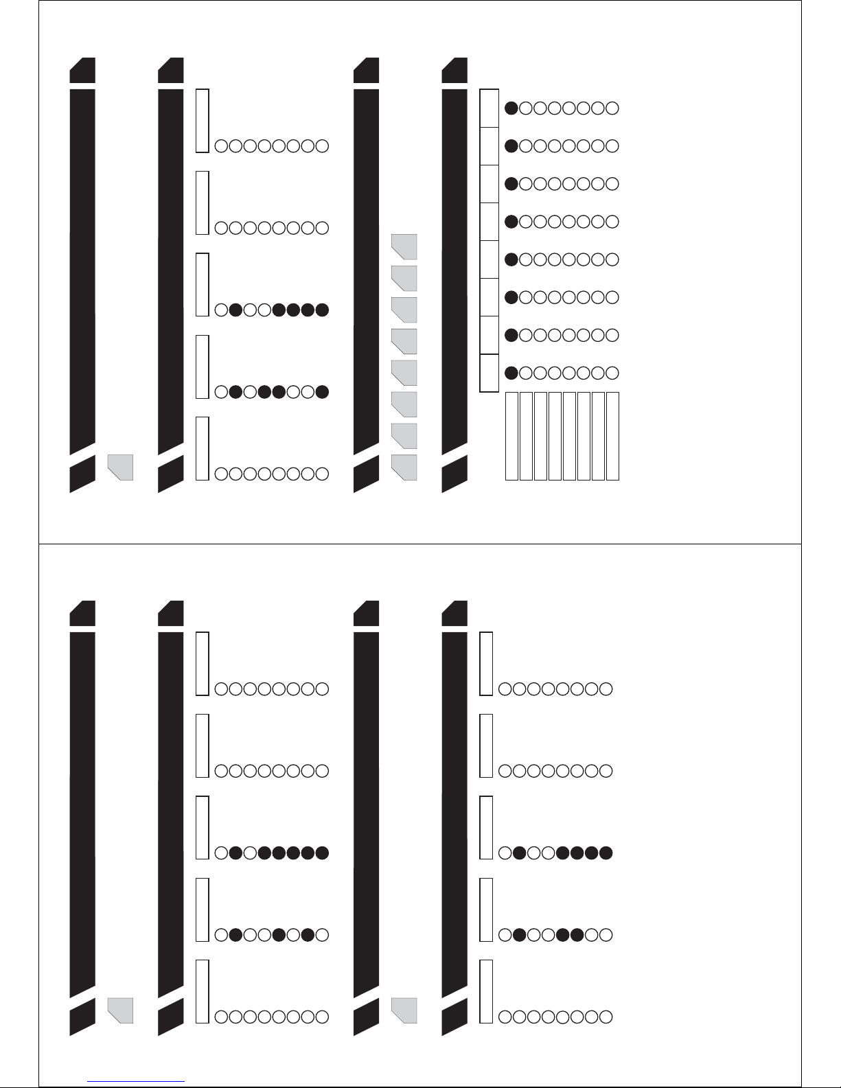
Pg
50
Configuration Group 18 - Alarm Event Code
101
Feat.
3
Pg
50
Configuration Group 18 - Characteristic Select
102
Feat.
Segment 1 Segment 2
11
2 2
Segment 3 Segment 5Segment 4
1 1
2
1
22
Fire
24 hour
Code pad beep
Yelping siren
Reserved
DEOL Tamper
Zone Activity
Resistor Defeat
Reserved
Reserved
Pg
50
Configuration Group 19 - Characteristic Select
104
Feat.
Segment 1 Segment 2
4
1
3
123
7
8
5
2
Segment 3 Segment 5Segment 4
1
3
4
5
123
678
4
5
123
678
72685
Fire
Delay 1
Follower
Local only
24 hour
Delay 2
Key-switch
Reserved
Code pad beep
Bypass
Chime
Partial Mode
Yelping siren
Group Bypass
Steady siren
Force Arm
Reserved
Dialer Delay
Twin Trip
Reserved
DEOL Tamper
Siren / Comm
Trouble
Restore
Zone Activity
Reserved
Access Control
Reserved
Resistor Defeat
Reserved
Request to Exit
Reserved
Reserved
Reserved
Reserved
Reserved
Reserved
Reserved
Reserved
Reserved
Pg
50
Configuration Group 19 - Alarm Event Code
103
Feat.
3
33
685
3
453
678
453
678
7
685
Delay 1
Follower
Local only
Delay 2
Key-switch
Reserved
Bypass
Chime
Partial Mode
Group Bypass
Steady siren
Force Arm
Dialer Delay
Twin Trip
Reserved
Siren / Comm
Trouble
Restore
Reserved
Access Control
Reserved
Reserved
Request to Exit
Reserved
Reserved
Reserved
Reserved
Reserved
Reserved
Reserved
5
5
44
8
6 6
4
6
7
4
7
8
4
7
Pg
51
Configuration Group 20 - Alarm Event Code
105
Feat.
3
Pg
51
Configuration Group 20 - Characteristic Select
106
Feat.
Segment 1 Segment 2
1
3
6
123
7
8
5
2
Segment 3 Segment 5Segment 4
1
3
4
5
123
678
4
5
123
678
72685
Fire
Delay 1
Follower
Local only
24 hour
Delay 2
Key-switch
Reserved
Code pad beep
Bypass
Chime
Partial Mode
Yelping siren
Group Bypass
Steady siren
Force Arm
Reserved
Dialer Delay
Twin Trip
Reserved
DEOL Tamper
Siren / Comm
Trouble
Restore
Zone Activity
Reserved
Access Control
Reserved
Resistor Defeat
Reserved
Request to Exit
Reserved
Reserved
Reserved
Reserved
Reserved
Reserved
Reserved
Reserved
Reserved
564 4
7
8
4
Pg
51
Zone 49-56 Area Selection
120
Feat.
Area 1
Area 2
Area 3
Area 4
Area 5
Area 6
Area 7
Area 8
2 2 2 2 2 2 2 2
3 3 3 3 3 3 3 3
4 4 4 4 4 4 4 4
6 6 6 6 6 6 6 6
7 7 7 7 7 7 7 7
8 8 8 8 8 8 8 8
1 1 1 1 1 1 1 1
5 5 5 5 5 5 5 5
Segment 1
(Zone 49)
Segment 2
(Zone 50)
Segment 3
(Zone 51)
Segment 4
(Zone 52)
Segment 5
(Zone 53)
Segment 6
(Zone 54)
Segment 7
(Zone 55)
Segment 8
(Zone 56)
Pg
51
Zone 49-56 Configuration Groups
119
Feat.
16 16 16 16 16 16 1616
Page 80
Pg
51
Zone 65-72 Area Selection
124
Feat.
Area 1
Area 2
Area 3
Area 4
Area 5
Area 6
Area 7
Area 8
2 2 2 2 2 2 2 2
3 3 3 3 3 3 3 3
4 4 4 4 4 4 4 4
6 6 6 6 6 6 6 6
7 7 7 7 7 7 7 7
8 8 8 8 8 8 8 8
1 1 1 1 1 1 1 1
5 5 5 5 5 5 5 5
Segment 1
(Zone 65)
Segment 2
(Zone 66)
Segment 3
(Zone 67)
Segment 4
(Zone 68)
Segment 5
(Zone 69)
Segment 6
(Zone 70)
Segment 7
(Zone 71)
Segment 8
(Zone 72)
Pg
51
Zone 65-72 Configuration Groups
123
Feat.
16 1616 16 16 16 16 16
Pg
51
Zone 57-64 Area Selection
122
Feat.
Area 1
Area 2
Area 3
Area 4
Area 5
Area 6
Area 7
Area 8
2 2 2 2 2 2 2 2
3 3 3 3 3 3 3 3
4 4 4 4 4 4 4 4
6 6 6 6 6 6 6 6
7 7 7 7 7 7 7 7
8 8 8 8 8 8 8 8
1 1 1 1 1 1 1 1
5 5 5 5 5 5 5 5
Segment 1
(Zone 57)
Segment 2
(Zone 58)
Segment 3
(Zone 59)
Segment 4
(Zone 60)
Segment 5
(Zone 61)
Segment 6
(Zone 62)
Segment 7
(Zone 63)
Segment 8
(Zone 64)
Pg
51
Zone 57-64 Configuration Groups
121
Feat.
16 1616 16 16 16 16 16
Pg
52
Zone 81-88 Area Selection
128
Feat.
Area 1
Area 2
Area 3
Area 4
Area 5
Area 6
Area 7
Area 8
2 2 2 2 2 2 2 2
3 3 3 3 3 3 3 3
4 4 4 4 4 4 4 4
6 6 6 6 6 6 6 6
7 7 7 7 7 7 7 7
8 8 8 8 8 8 8 8
1 1 1 1 1 1 1 1
5 5 5 5 5 5 5 5
Segment 1
(Zone 81)
Segment 2
(Zone 82)
Segment 3
(Zone 83)
Segment 4
(Zone 84)
Segment 5
(Zone 85)
Segment 6
(Zone 86)
Segment 7
(Zone 87)
Segment 8
(Zone 88)
Pg
52
Zone 81-88 Configuration Groups
127
Feat.
16 1616 16 16 16 16 16
Pg
52
Zone 73-80 Area Selection
126
Feat.
Area 1
Area 2
Area 3
Area 4
Area 5
Area 6
Area 7
Area 8
2 2 2 2 2 2 2 2
3 3 3 3 3 3 3 3
4 4 4 4 4 4 4 4
6 6 6 6 6 6 6 6
7 7 7 7 7 7 7 7
8 8 8 8 8 8 8 8
1 1 1 1 1 1 1 1
5 5 5 5 5 5 5 5
Segment 1
(Zone 73)
Segment 2
(Zone 74)
Segment 3
(Zone 75)
Segment 4
(Zone 76)
Segment 5
(Zone 77)
Segment 6
(Zone 78)
Segment 7
(Zone 79)
Segment 8
(Zone 80)
Pg
52
Zone 73-80 Configuration Groups
125
Feat.
16 1616 16 16 16 16 16
Page 81
Pg
52
Zone 97-104 Area Selection
132
Feat.
Area 1
Area 2
Area 3
Area 4
Area 5
Area 6
Area 7
Area 8
2 2 2 2 2 2 2 2
3 3 3 3 3 3 3 3
4 4 4 4 4 4 4 4
6 6 6 6 6 6 6 6
7 7 7 7 7 7 7 7
8 8 8 8 8 8 8 8
1 1 1 1 1 1 1 1
5 5 5 5 5 5 5 5
Segment 1
(Zone 97)
Segment 2
(Zone 98)
Segment 3
(Zone 99)
Segment 4
(Zone 100)
Segment 5
(Zone 101)
Segment 6
(Zone 102)
Segment 7
(Zone 103)
Segment 8
(Zone 104)
Pg
52
Zone 97-104 Configuration Groups
131
Feat.
16 1616 16 16 16 16 16
Pg
52
Zone 89-96 Area Selection
130
Feat.
Area 1
Area 2
Area 3
Area 4
Area 5
Area 6
Area 7
Area 8
2 2 2 2 2 2 2 2
3 3 3 3 3 3 3 3
4 4 4 4 4 4 4 4
6 6 6 6 6 6 6 6
7 7 7 7 7 7 7 7
8 8 8 8 8 8 8 8
1 1 1 1 1 1 1 1
5 5 5 5 5 5 5 5
Segment 1
(Zone 89)
Segment 2
(Zone 90)
Segment 3
(Zone 91)
Segment 4
(Zone 92)
Segment 5
(Zone 93)
Segment 6
(Zone 94)
Segment 7
(Zone 95)
Segment 8
(Zone 96)
Pg
52
Zone 89-96 Configuration Groups
129
Feat.
16 1616 16 16 16 16 16
Pg
53
Zone 113-120 Area Selection
136
Feat.
Area 1
Area 2
Area 3
Area 4
Area 5
Area 6
Area 7
Area 8
2 2 2 2 2 2 2 2
3 3 3 3 3 3 3 3
4 4 4 4 4 4 4 4
6 6 6 6 6 6 6 6
7 7 7 7 7 7 7 7
8 8 8 8 8 8 8 8
1 1 1 1 1 1 1 1
5 5 5 5 5 5 5 5
Segment 1
(Zone 113)
Segment 2
(Zone 114)
Segment 3
(Zone 115)
Segment 4
(Zone 116)
Segment 5
(Zone 117)
Segment 6
(Zone 118)
Segment 7
(Zone 119)
Segment 8
(Zone 120)
Pg
53
Zone 113-120 Configuration Groups
135
Feat.
16 1616 16 16 16 16 16
Pg
53
Zone 105-112 Area Selection
134
Feat.
Area 1
Area 2
Area 3
Area 4
Area 5
Area 6
Area 7
Area 8
2 2 2 2 2 2 2 2
3 3 3 3 3 3 3 3
4 4 4 4 4 4 4 4
6 6 6 6 6 6 6 6
7 7 7 7 7 7 7 7
8 8 8 8 8 8 8 8
1 1 1 1 1 1 1 1
5 5 5 5 5 5 5 5
Segment 1
(Zone 105)
Segment 2
(Zone 106)
Segment 3
(Zone 107)
Segment 4
(Zone 108)
Segment 5
(Zone 109)
Segment 6
(Zone 110)
Segment 7
(Zone 111)
Segment 8
(Zone 112)
Pg
53
Zone 105-112 Configuration Groups
133
Feat.
16 1616 16 16 16 16 16
Page 82
Pg
53
Zone 121-128 Area Selection
138
Feat.
Area 1
Area 2
Area 3
Area 4
Area 5
Area 6
Area 7
Area 8
2 2 2 2 2 2 2 2
3 3 3 3 3 3 3 3
4 4 4 4 4 4 4 4
6 6 6 6 6 6 6 6
7 7 7 7 7 7 7 7
8 8 8 8 8 8 8 8
1 1 1 1 1 1 1 1
5 5 5 5 5 5 5 5
Segment 1
(Zone 121)
Segment 2
(Zone 122)
Segment 3
(Zone 123)
Segment 4
(Zone 124)
Segment 5
(Zone 125)
Segment 6
(Zone 126)
Segment 7
(Zone 127)
Segment 8
(Zone 128)
Pg
53
Zone 121-128 Configuration Groups
137
Feat.
16 1616 16 16 16 16 16
0
0=3k3, 1=1k5, 2=2k2, 3=3k9, 4=4k7, 5=5k6, 6=6k8
Segment 1
Pg
54
EOL Resistor Value Select
162
Feat.
Programming Sheets v1.0.11
Segment 1
(Area 1)
Segment 2
(Area 2)
Segment 3
(Area 3)
Segment 4
(Area 4)
Segment 5
(Area 5)
Segment 6
(Area 6)
Segment 7
(Area 7)
Segment 8
(Area 8)
SunSunSunSunSunSunSun
ThurThurThurThurThurThurThur
WedWedWedWedWedWedWed
ReservedReservedReservedReservedReservedReservedReserved
MonMonMonMonMonMonMon
FriFriFriFriFriFriFri
TueTueTueTueTueTueTue
SatSatSatSatSatSatSat
Pg
54
Days of the Week for Auto Disarm Areas 1-8
155
Feat.
1111111
3333333
6666666
5555555
8888888
4444444
7777777
2222222
Sun
Thur
Wed
Reserved
Mon
Fri
Tue
Sat
1
36584
7
2
Page 83

Hills Reliance Specifications
Operating Power 16.5 VAC 25, 40, or 50 VA Transformer
Auxiliary Power
W/ 25 VA Transformer 12 VDC Regulated 500 mA
W/ 40 or 50 VA
Transformer
12 VDC Regulated 1 Amp
W/ NX-320 Power Supply 12 VDC Regulated 3.5 Amps
Loop Resistance
Standard Loop 300 Ohms Maximum
2-Wire Smokes 30 Ohms Maximum
4-Wire Smokes 300 Ohms Maximum
Loop Response 500mS
Built-in Siren Driver 3-tone (Steady, Yelp, Evacuation)
Operating Temperature 0 to 48 degrees C
LED Code Pad Dimensions 16.25cm Wide
10.15cm High
2.8cm Deep
LCD Code Pad Dimensions 16.25cm Wide
13.45cm High
2.50cm Deep
Metal Enclosure Dimension 28.60cm Wide
28.60cm High
8.90cm Deep
Shipping Weight 4 kg
N4131
© 2006 Hills Industries
Warranty Statement
Hills Industries guarantees this product against defective parts and workmanship for twenty-four (24)
months from date of purchase. If any defect appears during the warranty period return it to place of
purchase. Hills Industries assumes no liability for consequential or indirect damage and accepts no
responsibility for repairing damage to the product caused by misuse, careless handling, or where
repairs have been made by others.
No other guarantee, written or verbal, is authorized by or on behalf of Hills Industries.
Hills Industries
12 Wiggs Rd Riverwood
NSW 2210 Australia
Phone (02) 9717 5222
Page 84

Reliance 128 Installation Manual v1-0-30.doc
Quick Start Guide
Short form programming sheet for a monitored system
This is not a substitute for reading the manual
1. Hard Default Panel Unplug battery & remove power, turn on power,
Enter 971300 within 10 seconds,
Wait 12 seconds
Repeat
2. Go To Program Mode *8 9713 0#
3. Soft Default Panel 910#, Exit, Exit, [Chime], wait 12 seconds
4. Go To Program Mode *8 9713 0#
5. Change Program Code 1# n*n*n*n* #
6. Duress Code 3# n*n*n*n* #
7. Receiver Phone #1 4# n*n*n*n*n*n*n*n* #
8. System Account Code 5# n*n*n*n* #
9. Communication Format 6# 1* (1 for CID, or 3 for Domestic Dial)
10. Receiver Phone #2 7# n*n*n*n*n*n*n*n* #
11. Report Event Summary 9# 3 7 *# (for open/close, tamper/restore)
12. Phone Cut Delay 11# n*
13. Download Access Code 12# n*n*n*n*n*n*n*n*
14. Download Control (Remote Access) 14# 1* (to enable two call AMD)
15. Force Arm Globally 16# 3*#
16. Entry/Exit Time #1 & #2 17# nn*nn*nn*nn* #
17. Configuration Groups (Zone Types) 18# (zones 1-8), 21# (zones 9-16),
59# (zones 17-24), 61# (zones 25-32),
63# (zones 33-40), 65# (zones 41-48),
119# (zones 49-56), 121# (zones 57-64)
18. System Options 22# 7*7* # (for siren on tamper and
[*][44] manual communicator test enable)
19. Medical Alarm Sounder “ON” 24# 7* (enable code pad beeping)
20. Auto Test Control 32# (see Feature 32 for details)
21. Exit Program Mode Press Exit, Exit, [Chime] wait 12 seconds
22. Change Master Code (default 1234) [*5] [Master Code] [01] [New Code] #
23. Program User Codes [*5] [Master Code] [User] [User Code] #
24. Set Date & Time (at User Level)
Set System Calendar [*][9][6] [Master Code] [Day of Week]
[Month] [Day of Month] [Year]
Set System Clock [*][9][7] [Master Code] [Hour] [Minutes]
25. Walk Test * [Chime] [Master Code]
End Walk Test [Master Code]
26. Train Client/End User
Note if testing reporting, master code does not send open/closing reports by default (see Feature 2)
 Loading...