

Page 1

Network Video Recorder
NVR-CH4
NVR-CH8
NVR-CH16
Quick Guide
Page 2

1
TABLE OF CONTENTS
Overview ......................................................................................................................................................... 2
Front Panel ................................................................................................................................................. 2
Rear Panel .................................................................................................................................................. 8
Peripheral Connections ................................................................................................................................. 10
Wiring of Alarm Input .............................................................................................................................. 10
Wiring of Alarm Output ........................................................................................................................... 10
Using of Alarm Connectors ...................................................................................................................... 10
Accessing via Local Display........................................................................................................................... 11
Menu Structure ......................................................................................................................................... 11
Startup and Shutdown .............................................................................................................................. 12
Live View ................................................................................................................................................. 12
Adding IP Cameras .................................................................................................................................. 12
Recording ................................................................................................................................................. 14
Instant Recording ............................................................................................................................. 14
All-day Recording ............................................................................................................................ 15
Playback ................................................................................................................................................... 15
Backup ..................................................................................................................................................... 17
Accessing via Web Browser ........................................................................................................................... 20
Logging In ................................................................................................................................................ 20
Live View ................................................................................................................................................. 20
Recording ................................................................................................................................................. 22
Playback ................................................................................................................................................... 23
Log ........................................................................................................................................................... 24
Specifications ....................................................................................................... Error! Bookmark not defined.
HDD Storage Calculation Chart ............................................................................................................... 27
Page 3

2
Overview
Front Panel
NVR-4Channel (NVR-CH4)
No.
Name
Description
1
Status
Indicator
Power
Power indicator turns yellow when system is running.
Status
Status indicator blinks red when data is being read from or written
to HDD.
Tx/Rx
Tx/Rx indictor blinks yellow when network connection is
functioning properly.
2
Control
Buttons
DIRECTION
In menu mode, the direction buttons are used to navigate between
different fields and items and select setting parameters.
In playback mode, the Up and Down buttons are used to speed up
and slow down record playing, and the Left and Right buttons are
used to move the recording 30s forward or backward.
In the image setting interface, the up and down button can adjust
the level bar of the image parameters.
In live view mode, these buttons can be used to switch channels.
ENTER
The Enter button is used to confirm selection in menu mode; or
used to check checkbox fields and ON/OFF switch.
In playback mode, it can be used to play or pause video.
In single-frame play mode, pressing the Enter button will play the
video by a single frame.
In auto sequence view mode, the buttons can be used to pause or
resume auto sequence.
3
Composite
Keys
SHIFT
Switch between the numeric or letter input and functions of the
composite keys. (Input letter or numbers when the light is out;
Realize functions when the light is red.)
1/MENU
Enter numeral “1”;
Access the main menu interface.
2/ABC/F1
Enter numeral “2”;
Enter letters “ABC”;
The F1 button when used in a list field will select all items in the
list.
In PTZ Control mode, it will turn on/off PTZ light and when the
image is zoomed in, the key is used to zoom out.
3/DEF/F2
Enter numeral “3”;
Enter letters “DEF”;
Overview 1
Page 4

3
The F2 button is used to change the tab pages.
In PTZ control mode, it zooms in the image.
4/GHI/ESC
Enter numeral “4”;
Enter letters “GHI”;
Exit and back to the previous menu.
5/JKL/EDIT
Enter numeral “5”;
Enter letters “JKL”;
Delete characters before cursor;
Check the checkbox and select the ON/OFF switch;
Start/stop record clipping in playback.
6/MNO/PLAY
Enter numeral “6”;
Enter letters “MNO”;
Playback, for direct access to playback interface.
7/PQRS/REC
Enter numeral “7”;
Enter letters “PQRS”;
Open the manual record interface.
8/TUV/PTZ
Enter numeral “8”;
Enter letters “TUV”;
Access PTZ control interface.
9/WXYZ/PREV
Enter numeral “9”;
Enter letters “WXYZ”;
Multi-channel display in live view.
0/A
Enter numeral “0”;
Shift the input methods in the editing text field. (Upper and
lowercase, alphabet, symbols or numeric input).
Double press the button to switch the main and auxiliary output.
4
USB Interfaces
Universal Serial Bus (USB) ports for additional devices such as
USB mouse and USB Hard Disk Drive (HDD)
NVR-8Channel (NVR-CH8)
No.
Name
Function Description
1
Status
Indicators
POWER
Turns green when NVR is powered up.
READY
The LED is green when the device is running normally.
STATUS
The light is green when the IR remote control is enabled;
The light is red when the function of the composite keys (SHIFT)
are used;
The light is out when none of the above conditions are met.
ALARM
The light is red when there is an alarm occurring.
HDD
Blinks red when HDD is reading/writing.
Page 5

4
No.
Name
Function Description
Tx/Rx
Blinks green when network connection is functioning normally.
2
Control
Buttons
DIRECTION
In menu mode, the direction buttons are used to navigate between
different fields and items and select setting parameters.
In playback mode, the Up and Down buttons are used to speed up
and slow down record playing, and the Left and Right buttons are
used to move the recording 30s forwards or backwards.
In the image setting interface, the up and down button can adjust
the level bar of the image parameters.
In live view mode, these buttons can be used to switch channels.
ENTER
The Enter button is used to confirm selection in menu mode; or
used to check checkbox fields and ON/OFF switch.
In playback mode, it can be used to play or pause video.
In single-frame play mode, pressing the Enter button will play the
video by a single frame.
In auto sequence view mode, the buttons can be used to pause or
resume auto sequence.
3
Composite
Keys
SHIFT
Switch between the numeric or letter input and functions of the
composite keys. (Input letter or numbers when the light is out;
Realize functions when the light is red.)
1/MENU
Enter numeral “1”;
Access the main menu interface.
2/ABC/F1
Enter numeral “2”;
Enter letters “ABC”;
The F1 button when used in a list field will select all items in the
list.
In PTZ Control mode, it will turn on/off PTZ light and when the
image is zoomed in, the key is used to zoom out.
3/DEF/F2
Enter numeral “3”;
Enter letters “DEF”;
The F2 button is used to change the tab pages.
In PTZ control mode, it zooms in the image.
4/GHI/ESC
Enter numeral “4”;
Enter letters “GHI”;
Exit and back to the previous menu.
5/JKL/EDIT
Enter numeral “5”;
Enter letters “JKL”;
Delete characters before cursor;
Check the checkbox and select the ON/OFF switch;
Start/stop record clipping in playback.
6/MNO/PLAY
Enter numeral “6”;
Enter letters “MNO”;
Playback, for direct access to playback interface.
7/PQRS/REC
Enter numeral “7”;
Enter letters “PQRS”;
Page 6

5
No.
Name
Function Description
Open the manual record interface.
8/TUV/PTZ
Enter numeral “8”;
Enter letters “TUV”;
Access PTZ control interface.
9/WXYZ/PRE
V
Enter numeral “9”;
Enter letters “WXYZ”;
Multi-channel display in live view.
0/A
Enter numeral “0”;
Shift the input methods in the editing text field. (Upper and
lowercase, alphabet, symbols or numeric input).
Double press the button to switch the main and auxiliary output.
4
USB Interfaces
Universal Serial Bus (USB) ports for additional devices such as
USB mouse and USB Hard Disk Drive (HDD).
NVR-16Channel (NVR-CH16)
No.
Name
Function Description
1
Status
Indicators
POWER
Turns green when NVR is powered up.
READY
The LED is green when the device is running normally.
STATUS
The light is green when the IR remote control is enabled;
The light is red when the function of the composite keys (SHIFT)
are used;
The light is out when none of the above condition is met.
ALARM
The light is red when there is an alarm occurring.
HDD
Blinks red when HDD is reading/writing.
Tx/Rx
Blinks green when network connection is functioning normally.
2
DVD-R/W
Slot for DVD-R/W.
3
Control
Buttons
DIRECTION
In menu mode, the direction buttons are used to navigate between
different fields and items and select setting parameters.
In playback mode, the Up and Down buttons are used to speed up
and slow down record playing, and the Left and Right buttons are
used to move the recording 30s forwards or backwards.
In the image setting interface, the up and down button can adjust
the level bar of the image parameters.
Page 7

6
No.
Name
Function Description
In live view mode, these buttons can be used to switch channels.
ENTER
The Enter button is used to confirm selection in menu mode; or
used to check checkbox fields and ON/OFF switch.
In playback mode, it can be used to play or pause video.
In single-frame play mode, pressing the Enter button will play the
video by a single frame.
In auto sequence view mode, the buttons can be used to pause or
resume auto sequence.
4
Composite
Keys
SHIFT
Switch between the numeric or letter input and functions of the
composite keys. (Input letter or numbers when the light is out;
Realize functions when the light is red.)
1/MENU
Enter numeral “1”;
Access the main menu interface.
2/ABC/F1
Enter numeral “2”;
Enter letters “ABC”;
The F1 button when used in a list field will select all items in the
list.
In PTZ Control mode, it will turn on/off PTZ light and when the
image is zoomed in, the key is used to zoom out.
3/DEF/F2
Enter numeral “3”;
Enter letters “DEF”;
The F2 button is used to change the tab pages.
In PTZ control mode, it zooms in the image.
4/GHI/ESC
Enter numeral “4”;
Enter letters “GHI”;
Exit and back to the previous menu.
5/JKL/EDIT
Enter numeral “5”;
Enter letters “JKL”;
Delete characters before cursor;
Check the checkbox and select the ON/OFF switch;
Start/stop record clipping in playback.
6/MNO/PLAY
Enter numeral “6”;
Enter letters “MNO”;
Playback, for direct access to playback interface.
7/PQRS/REC
Enter numeral “7”;
Enter letters “PQRS”;
Open the manual record interface.
8/TUV/PTZ
Enter numeral “8”;
Enter letters “TUV”;
Access PTZ control interface.
9/WXYZ/PRE
V
Enter numeral “9”;
Enter letters “WXYZ”;
Multi-channel display in live view.
0/A
Enter numeral “0”;
Page 8
7
No.
Name
Function Description
Shift the input methods in the editing text field. (Upper and
lowercase, alphabet, symbols or numeric input).
Double press the button to switch the main and auxiliary output.
5
JOG SHUTTLE Control
Move the active selection in a menu. It will move the selection up
and down.
In Live View mode, it can be used to cycle through different
channels.
In the Playback mode, it can be used to jump 30s
forward/backward in video files.
In PTZ control mode, it can control the movement of the PTZ
camera. 6 POWER ON/OFF
Power on/off switch.
7
USB Interfaces
Universal Serial Bus (USB) ports for additional devices such as
USB mouse and USB Hard Disk Drive (HDD).
Page 9

8
Rear Panel
NVR-4Channel (NVR-CH4)
NVR-8Channel (NVR-CH8)
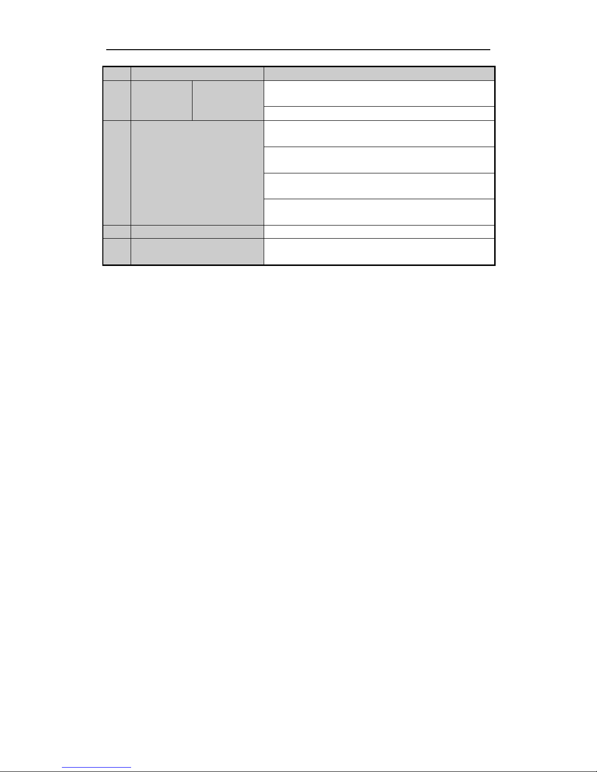
No.
Item
Description
1
Power Supply
48V DC power supply for NVR-CH4 and AC 100~240V for
NVR-CH8.
2
Audio In
RCA connector for audio input.
3
HDMI Interface
HDMI video output connector.
4
LAN Network Interface
1 10 /100 /1000 Mbps self-adaptive Ethernet interface
5
Audio Out
RCA connector for audio output.
6
VGA Interface
DB9 connector for VGA output. Display local video output and menu.
7
USB Interface
Universal Serial Bus (USB) ports for additional devices such as USB
mouse and USB Hard Disk Drive (HDD).
8
Ground
Ground (needs to be connected when NVR starts up).
9
Power Switch
Switch for turning on/off the device.
10
Network Interfaces with
PoE function
Network interfaces for the cameras and power over Ethernet.
Page 10
9
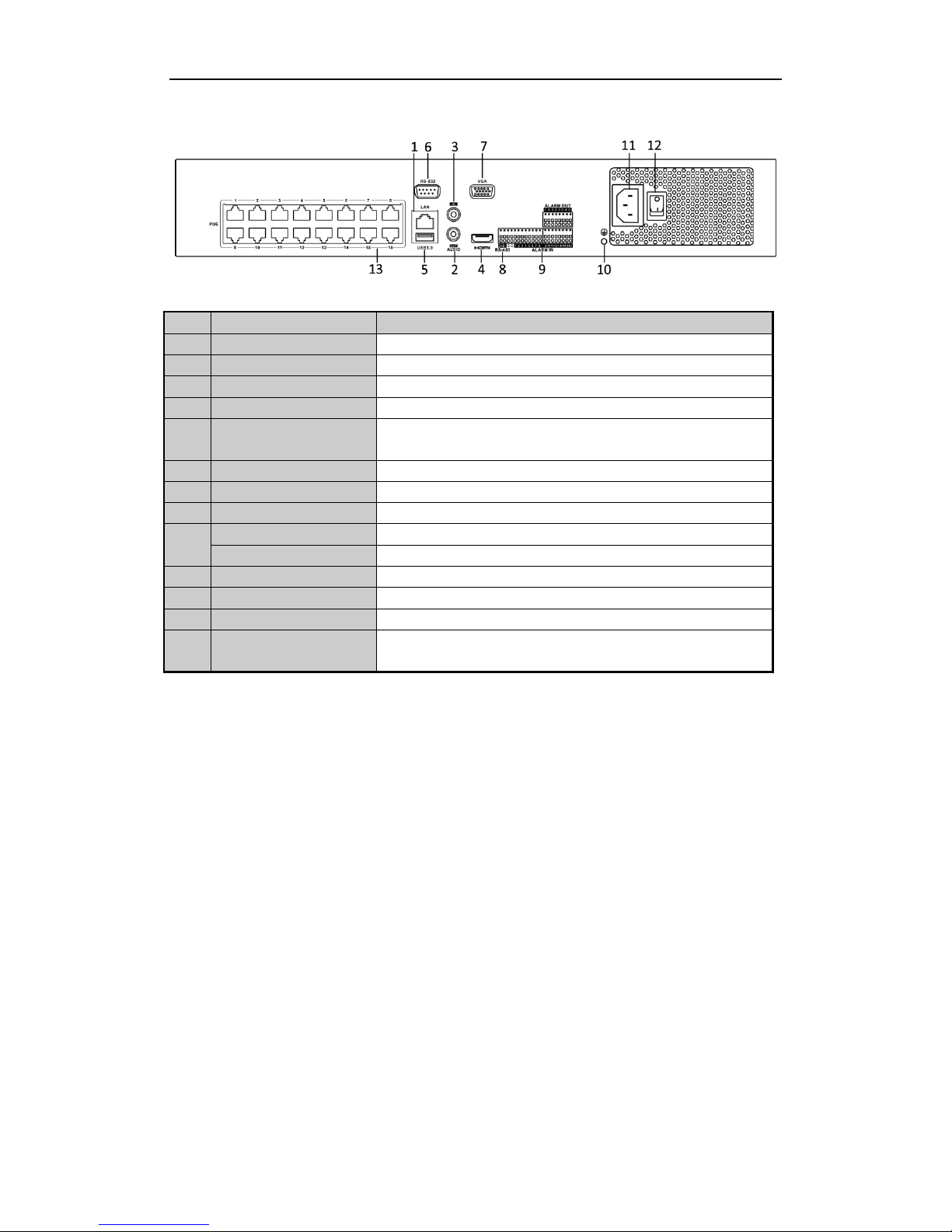
NVR-16Channel (NVR-CH16)
No.
Item
Description
1
LAN Interface
1 network interface
2
AUDIO OUT
RCA connector for audio output.
3
LINE IN
RCA connector for audio input.
4
HDMI
HDMI video output connector.
5
USB 3.0 interface
Universal Serial Bus (USB) ports for additional devices such as USB
mouse and USB Hard Disk Drive (HDD).
6
RS-232 Interface
Connector for RS-232 devices.
7
VGA
DB9 connector for VGA output. Display local video output and menu.
8
RS-485 Interface
Half-duplex connector for RS-485 devices.
9
ALARM IN
Connector for alarm input.
ALARM OUT
Connector for alarm output.
10
GROUND
Ground (needs to be connected when NVR starts up).
11
AC 100V ~ 240V
100V ~ 240V AC power supply.
12
Power Switch
Switch for turning on/off the device.
13
Network Interfaces with
PoE function
Network interfaces for the cameras and power over Ethernet.
Page 11
10
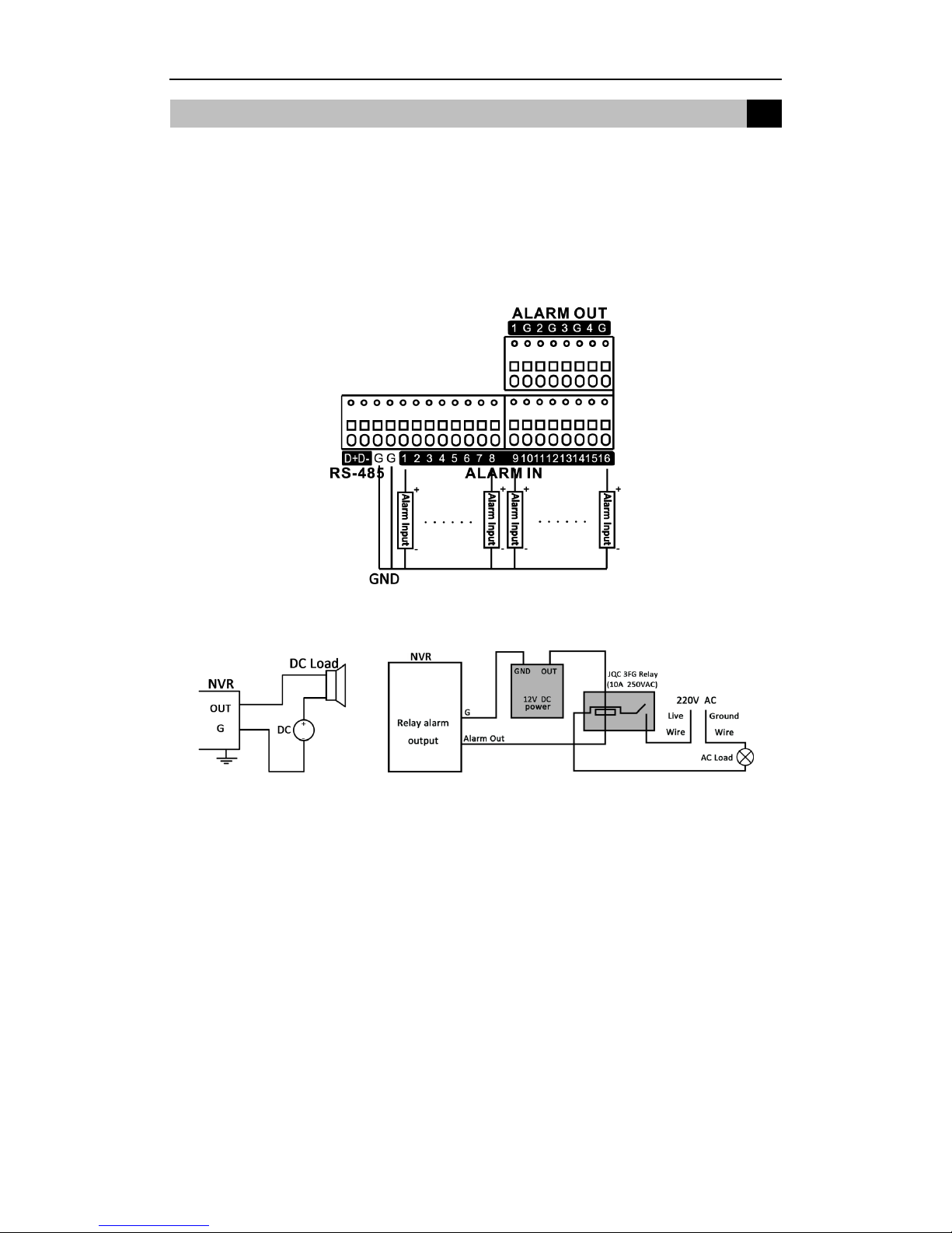
Wiring of Alarm Input
The alarm input is an open/closed relay. To connect the alarm input to the device, use the following diagram.
Note:
If the alarm input is not an open/close relay, please connect an external relay between the alarm input and the
device.
Wiring of Alarm Output
To connect to an alarm output (AC or DC load), use the following diagram:
DC Load Connection Diagram AC Load Connection Diagram
For DC load, the jumpers can be used within the limit of 12V/1A safely.
To connect an AC load, jumpers should be left open (you must remove the jumper on the motherboard in the
NVR). Use an external relay for safety (as shown in the figure above).
There are 4 jumpers (JP1, JP2, JP3, and JP4) on the motherboard, each corresponding with one alarm output. By
default, jumpers are connected. To connect an AC load, jumpers should be removed.
Example:
If you connect an AC load to the alarm output 3 of the NVR, then you must remove the JP 3.
Using of Alarm Connectors
To connect alarm devices to the NVR:
1. Disconnect pluggable block from the ALARM IN /ALARM OUT terminal block.
2. Unfasten stop screws from the pluggable block, insert signal cables into slots and fasten stop screws. Ensure
signal cables are in tight.
3. Connect pluggable block back into terminal block.
Peripheral Connections
2
2
Page 12
11
Menu Structure
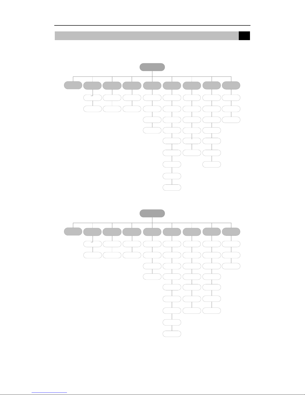
The menu structure NVR-4CH and NVR-8CH:
Menu
Export Manual HDD Camera
Maintenance
Shutdown
Record
Configuration
Playback
Normal Record General Schedule Camera General
System Info
Logout
Event Advanced Parameters OSD
Network
Log
Information
Shutdown
Advanced
Image
Import/Export
Reboot
Holiday PTZ
Upgrade
Motion
Live View
Default
Privacy
Mask
Exceptions
Net Detect
Video
Tampering
User
Video Loss
HDD Detect
Alarm
Alarm
VCA
The menu structure of NVR-16CH:
Menu
Export Manual HDD Camera
Maintenance
Shutdown
Record
Configuration
Playback
Normal Record General Schedule Camera General
System Info
Logout
Event Advanced Parameters OSD
Network
Log
Information
Shutdown
Advanced
Image
Import/Export
Reboot
Holiday PTZ
Upgrade
Motion
Live View Default
Privacy
Mask
Exceptions
Net Detect
Video
Tampering
User
Video Loss
HDD Detect
Alarm
Alarm
RS-232
VCA
Accessing via Local Display
3
Page 13
12
Startup and Shutdown
Proper startup and shutdown procedures are crucial to extend the life of the NVR.
To start your NVR:
Steps:
1. Check the power supply is plugged into an electrical outlet. It is HIGHLY recommended that an
Uninterruptible Power Supply (UPS) be used in conjunction with the device. The Power button on the front
panel should be red, indicating that the device has power.
2. Press the POWER button on the front panel. The Power LED should turn blue or green. The unit will begin
to start.
After the device startup, the wizard will guide you through the initial settings, including modifying password,
date and time settings, network settings, HDD initializing, and recording.
Note: For admin login, default password is ‘admin’. Please change it in wizard immediately.
To shut down the NVR:
Steps:
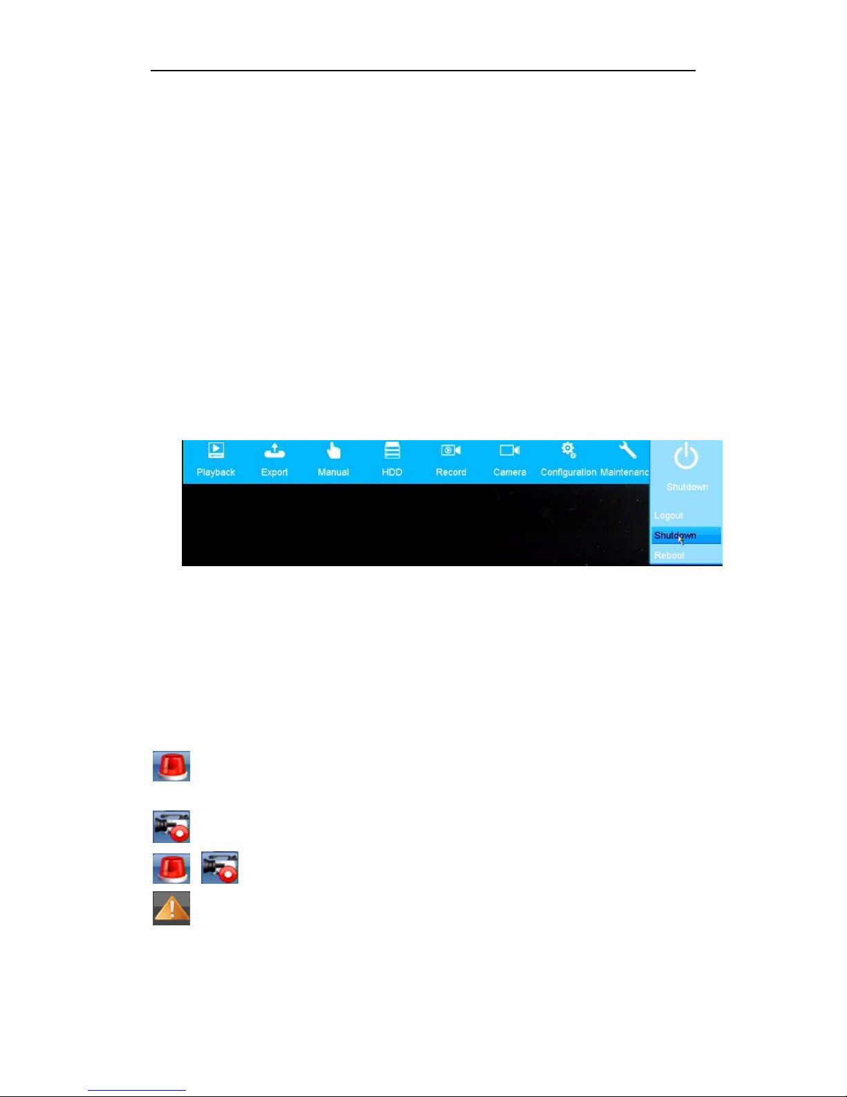
1. Enter the Shutdown menu.
Right Click – Menu -Shutdown
2. Select the Shutdown button.
Live View
Some icons are provided on screen in Live View mode to indicate different camera status. These icons include:
Live View Icons
In the live view mode, there are icons at the upper-right corner of the screen for each channel, showing the status
of the record and alarm in the channel, so that you can see any problems as soon as possible.
Alarm (video loss, tampering, motion detection or sensor alarm)
Record (manual record, continuous record, motion detection or alarm triggered record)
Alarm & Record
Event/Exception (event and exception information, appears at the lower-left corner of the screen.)
Adding IP Cameras
You should add and configure the online IP cameras to enable the live view and recording function.
Page 14
13
Steps:
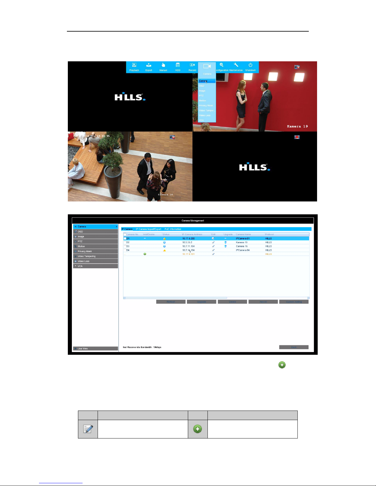
1. Right-click the mouse when you in the live view mode to show the right-click menu.
2. Select Camera in the pop-up menu to enter the Camera Management interface.
3. The online cameras with same network segment will be displayed in the camera list. Click the button to
add the camera.
Note:
The added camera is marked in black while the camera has not been added is marked in yellow.
Explanation of the icons
Icon
Explanation
Icon
Explanation
Edit basic parameters of the camera
Add the detected IP camera.
Page 15
14
Icon
Explanation
Icon
Explanation
The camera is connected.
The camera is disconnected; you can
click the icon to get the exception
information of camera.
Delete the IP camera
Advanced settings of the camera.
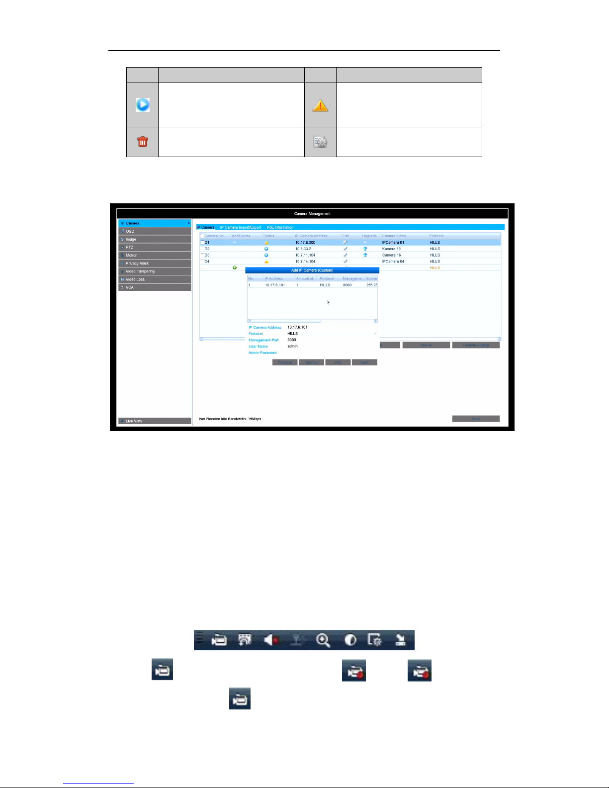
4. To add other IP cameras:
1) Click the Custom Adding button to pop up the Add IP Camera (Custom) interface.
2) You can edit the IP address, protocol, management port, and other information of the IP camera to be
added.
3) Click Add to add the camera.
Recording
Two record types are introduced in the following section, Instant Record and All-day Record. For other record
types please refer to the user manual for detailed information.
Note:
After rebooting all the manual records enabled are cancelled.
Instant Recording
On the live view window of each channel, there is a quick setting toolbar which shows on the bottom of the
window when you click on it.
Click the icon to enable the record, and the icon turns to . And click icon to disable the
record, then the icon will turn to .
Page 16
15
All-day Recording
Steps:
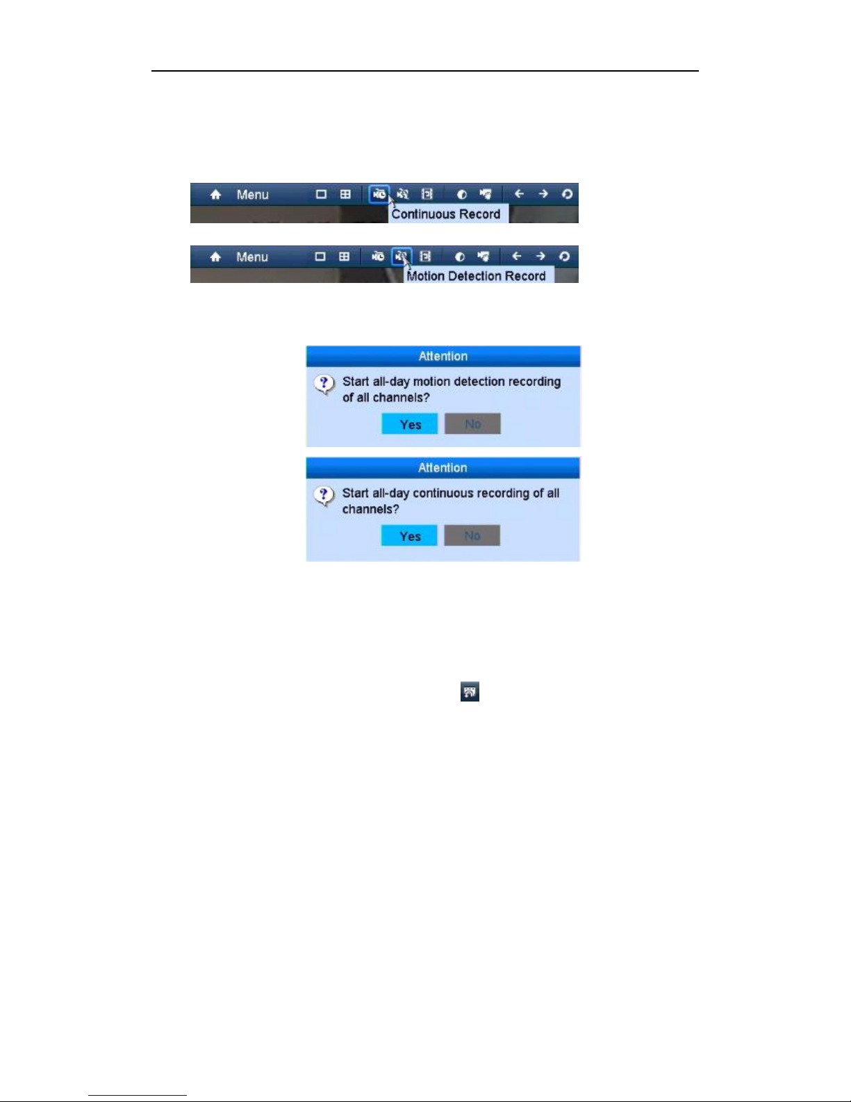
1. On the live view window, right lick the window and move the cursor to the Start Recording option, and
select Continuous Record or Motion Detection Record on your demand.
2. And click the Yes button in the popup Attention message box to confirm the settings.
Then all the channels will start to record in the selected mode.
Playback
Play back the record files of a specific channel in the live view menu. Channel switch is supported.
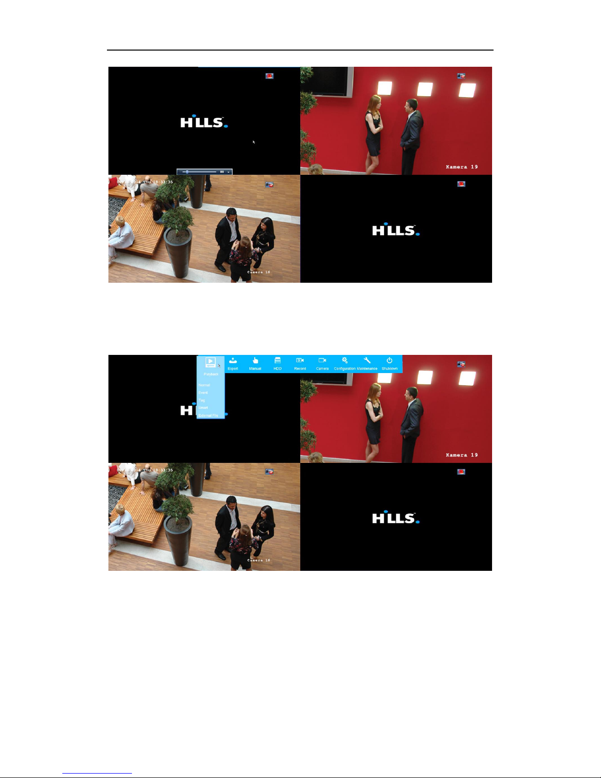
Option 1:
Choose a channel under live view using the mouse and click the button in the shortcut operation menu.
Note:
Only files recorded in the past five minutes on this channel will be played back.
Page 17
16
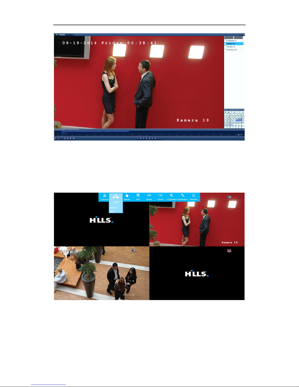
Option 2:
Steps:
1. Enter the Playback menu.
Mouse: right click a channel in live view mode and select Playback from the menu.
Under multi-screen live view, record files of the selected channel will be played back.
Note:
Pressing numerical buttons will switch playback to related channels during playback process.
2. Playback management.
The toolbar in the bottom part of Playback interface can be used to control playing process.
Page 18
17
Just check the channel or channels if you want to switch playback to another channel or execute
simultaneous playback of multiple channels.
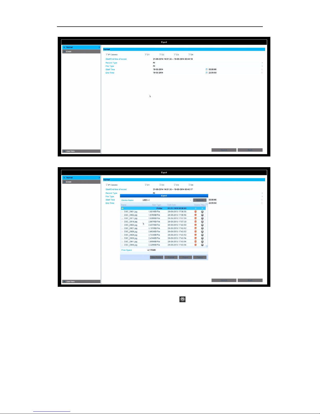
Backup
Recorded files can be backed up to various devices, such as USB flash drives, USB HDDs or a DVD writer.
Steps:
1. Enter Export menu
2. Select IP Camera.
Choose the channel(s) you want to back up and click on the Search button.
Page 19
18
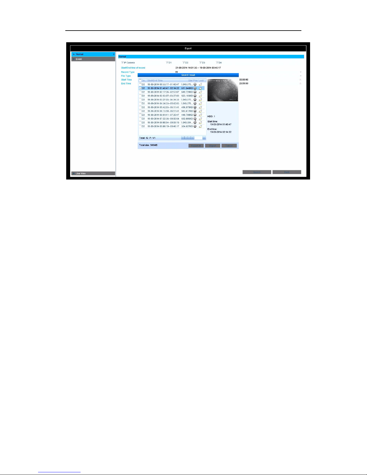
3. Select backup device and click Export button to start exporting.
4. Check backup result.
Choose the recording file in Export interface and click button to check it.
Page 20
19
Page 21
20
Accessing via Web Browser
Logging In
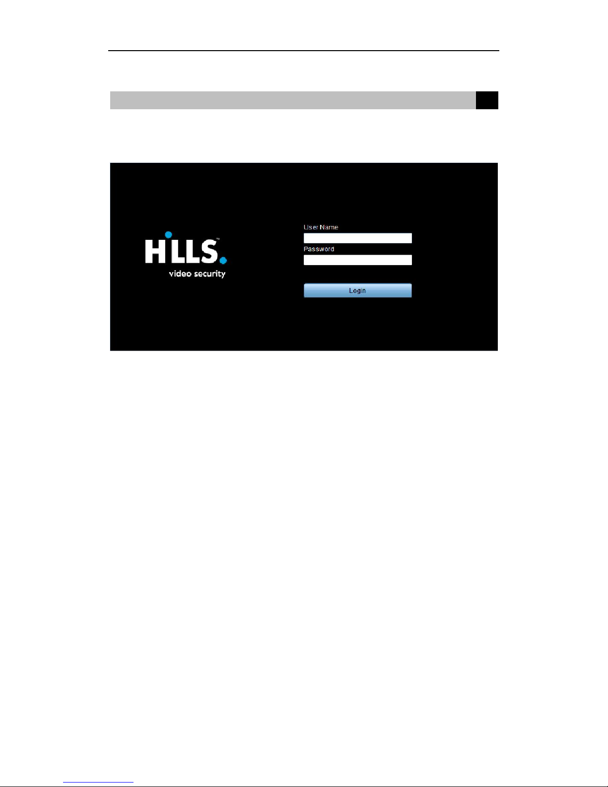
You can get access to the device via web browser. Open a web browser, input the IP address of the device and then
press Enter. The login interface appears:
Input the user name and password, and click the Login button.
Note:
By default DHCP client is enabled. NVR will search for DHCP server for 30 seconds if the network doesn’t
have a DHCP server then NVR will switch to fixed IP address.
The default IP address is 10.2.2.2 and Subnet mask 255.0.0.0.
The default user name is admin, and password is admin.
You may use one of the following listed web browsers: Internet Explorer 6.0, Internet Explorer 7.0, Internet
Explorer 8.0, Internet Explorer 9.0, Internet Explorer 10.0, Apple Safari, Mozilla Firefox, and Google
Chrome.
The supported resolutions include 1024*768 and above.
When you log in for the first time, the system will remind you to install the Plug-in control. After the installation,
you can configure and manage the device remotely.
Live View
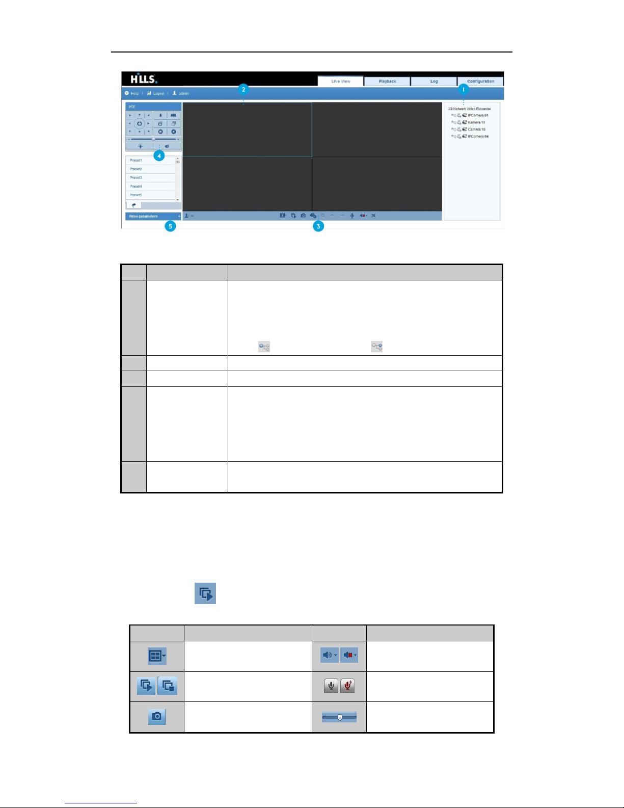
The live view interface appears by default when you log in the device.
Accessing via Web Browser
4
Page 22
21
Interface Introduction
No.
Name
Description
1
Channel List
Displays the list of channels and the playing and recording status of each
channel.
Note:
The stream type can be switched by clicking the icon before the channel
name: stands for main stream and for sub-stream.
2
Live View Window
Displays the image of channel, and multi-window division is supported.
3
Play Control Bar
Play control operations are supported.
4
PTZ Control
Pan, tilt, zoom operations are supported, as well as preset editing and
calling.
Note:
PTZ function can only be realized if the connected camera supports PTZ
control.
5
Video Parameters
Configuration
Brightness, contrast, saturation and hue of the image can be adjusted.
Start Live View
Steps:
1. In the live view window, select a playing window by clicking the mouse.
2. Double click a camera from the device list to start the live view.
3. You can click the button on the toolbar to start the live view of all cameras on the device list.
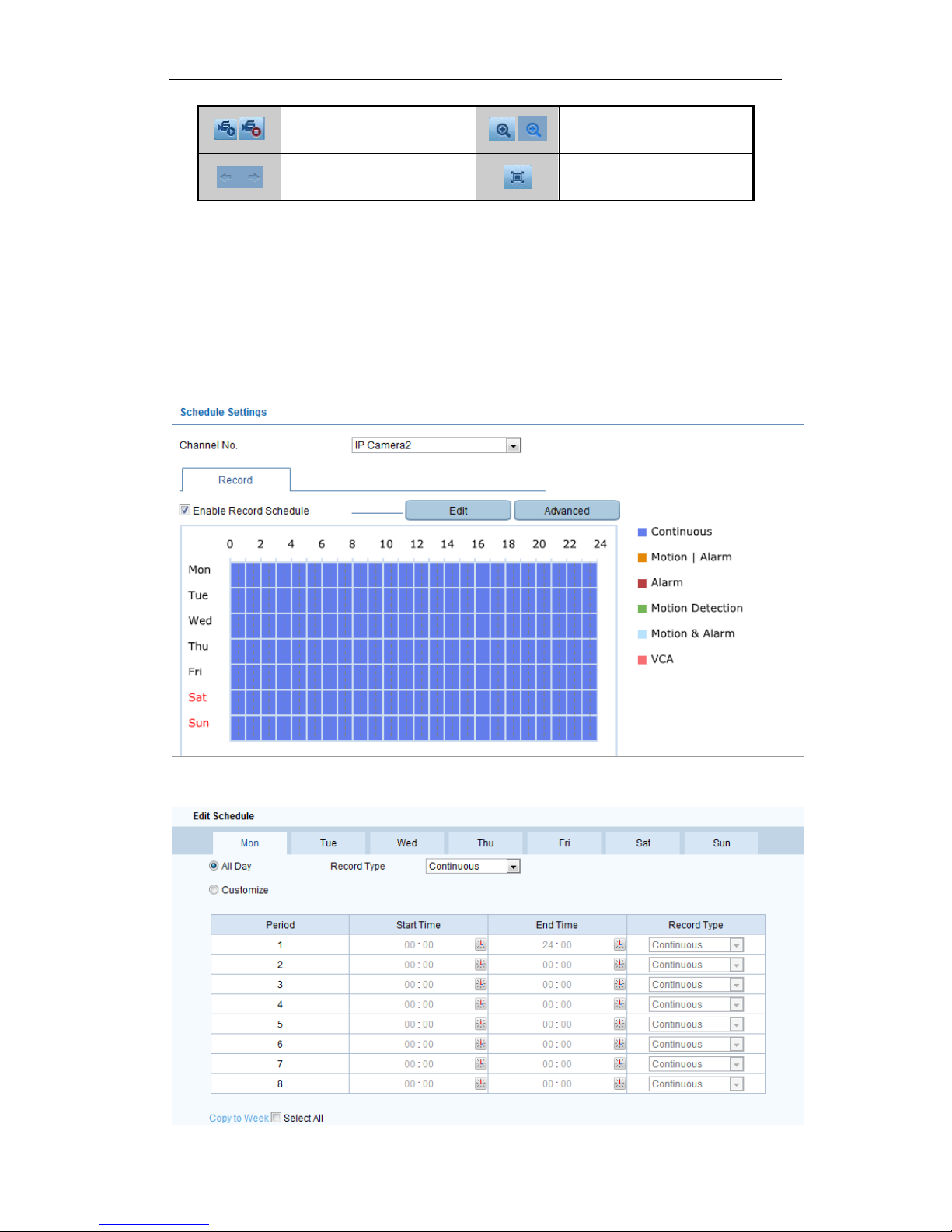
Refer to the following table for the description of buttons on the live view window:
Icon
Description
Icon
Description
Select the window-division mode
/
On/Off audio
/
Start/Stop all live view
/
Start/Stop two-way Audio
Capture pictures in the live view
mode
Adjust volume
Page 23
22
/
Start/Stop all recording
/
Enable/Disable digital zoom
Previous/Next page
Full screen
Recording
Two recording types can be configured: Manual and Scheduled. The following section introduces the
configuration of scheduled recording.
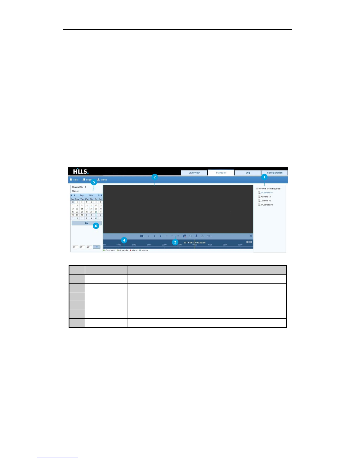
Steps:
1. Click Remote Configuration> Camera Settings> Record Schedule to enter Record Schedule settings
interface.
2. Select the camera to configure the record schedule.
3. Check the checkbox of Enable Schedule to enable recording schedule.
4. Choose the day in a week to configure scheduled recording.
5. Click Edit to edit record schedule.
Page 24
23
1) Configure All Day or Customize Record:
If you want to configure the all-day recording, please check the All Day checkbox.
If you want to record in different time sections, check the Customize checkbox. Set the Start
Time and End Time.
Note:
Up to 8 segments can be configured and each segment cannot be overlapped.
2) Select a Record Type. The record type can be Continuous, Motion, Alarm, Motion & Alarm, Motion |
Alarm and VCA.
3) Check the checkbox of Select All and click Copy to copy settings of this day to the whole week. You
can also check any of the checkboxes before the date and click Copy.
4) Click OK to save the settings and exit the Edit Schedule interface.
6. Click Advanced to configure advanced record parameters.
7. Click Save to activate the above settings.
Playback
Interface Introduction
No.
Name
Description
1
Channel List
Displays the list of channels and the playing status of each channel.
2
Playback Window
Displays the image of channel.
3
Play Control Bar
Play control operations are supported.
4
Time Line
Displays the time bar and the recording are marked with different colors.
5
Playback Status
Displays the playback status, including channel number and playback speed.
6
Calendar
Select the date to play.
Start Playback
Steps:
1. Click Playback on the menu bar to enter playback interface.
2. Click the camera from the device list for playback.
3. Select the date from the calendar and click Search.
4. Click the Play button to play the video file searched on the current date.
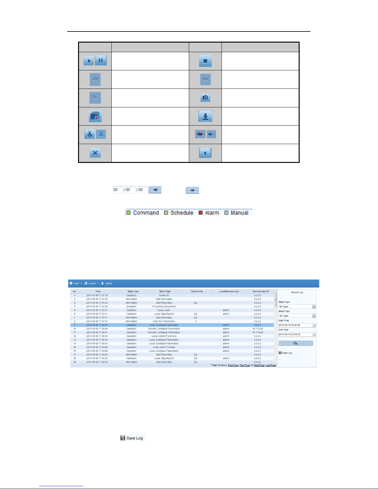
5. Use the buttons on the toolbar to operate in playback mode.
Page 25
24
Button
Description
Button
Description
/
Play/Pause
Stop Slow down
Speed up
Play by single frame
Capture
Stop all playback
Download
/
Video clip
/
Open/Close audio
Full screen
Reverse playback
6. You can drag the progress bar with the mouse to locate the exact playback point. You can also input the time
in the textbox and click button to locate the playback point.
The color of the video on the progress bar stands for the different video types.
Log
You can view and export the log files at any time, including operation, alarm, exception and information of device.
Before you start:
The Log function can be realized only when the device is connected with HDD or network disk.
Steps:
1. Click Log on the menu bar to enter the Log interface.
2. Set the log search conditions to refine your search, including the Major Type, Minor Type, Start Time and
End Time.
3. Click the Search button to start searching log files.
4. The matched log files will be displayed on the list.
Note:
Up to 2000 log files can be found each time, and 100 log files can be displayed on each page.
You can click the button to save the searched log files to local directory.
Page 26

25
Page 27
26
Model
NVR-CH4
NVR-CH8
NVR-CH16
Part no
S47094
S47095
S47096
Video/Audio
input
IP video input
4-ch
8-ch
16-ch
Two-way audio
input
1-ch, RCA (2.0 Vp-p, 1kΩ)
Network
Incoming
bandwidth
25Mbps
50Mbps
100Mbps
Outgoing
bandwidth
80Mbps
Remote
connection
128
Video/Audio
output
Recording
resolution
5MP/3MP/1080P/UXGA/720P/VGA/4CIF/DCIF/2CIF/CIF/QCIF
Frame rate
Main stream: 50 fps (P) / 60 fps (N)
Sub-stream: 50 fps (P) / 60 fps (N)
HDMI/VGA output
1-ch, resolution:
1920 × 1080P /60Hz, 1600 × 1200 /60Hz, 1280 × 1024 /60Hz,
1280 × 720 /60Hz, 1024 × 768 /60Hz
Audio output
1-ch, RCA (Linear, 1kΩ)
Decoding
Live view /
Playback
resolution
5MP/3MP/1080p/UXGA/720p/VGA/4CIF/DCIF/2CIF/CIF/QCIF
Capability
4-ch@1080P
8-ch@720P,
6-ch@1080P
16-ch@4CIF,
12-ch@720P,
6-ch@1080P
Hard disk
SATA
1x 3TB HDD
1x 3TB HDD
1x SATA interface
for 1x extra HDD
1x 3TB HDD
3x SATA interface
for 3x extra HDDs
eSATA (Optional)
1 eSATA interface
Capacity
Up to 4TB for each disk
External
interface
Network interface
1 RJ-45 10 /100 /1000 Mbps
self-adaptive Ethernet interface
2 RJ-45 10 /100
/1000 Mbps
self-adaptive
Ethernet interface
Serial interface
RS-232 and
RS-485
USB interface
1 × USB 2.0 and 1 × USB 3.0
2 × USB 2.0 and 1
× USB 3.0
Alarm in/out
(Optional)
4 / 1
16/4 (optionally can
be expanded to
16/8)
Specifications
5
Page 28
27
PoE
Interface
4 independent 100
PoE network
interface
8 independent 100
PoE network
interface
16 independent
100 PoE network
interface
Max. Power
50W
120W
200W
Supported
standard
AF and AT
Others
Power supply
48V DC
220V AC
100-240V AC
Consumption
(without hard disk)
≤ 10W
≤ 20W
Working
temperature
-10 ºC ~ +55 ºC (+14 ºF~ + 131 ºF)
Working humidity
10 % ~ 90 %
Chassis
1U chassis
19-inch rack 1U
chassis
19-inch rack 1.5U
chassis
Dimensions
(W × D × H)
315 × 230 × 45mm
(12.4 × 9.1 × 1.8 in)
445x290x45mm
(17.5x11.4x1.8in)
445x390x70mm
(17.5x15.3x2.8in)
Weight
(without hard disk)
≤ 1 Kg (2.2 lb)
≤ 4 Kg (8.82 lb)
HDD Storage Calculation Chart
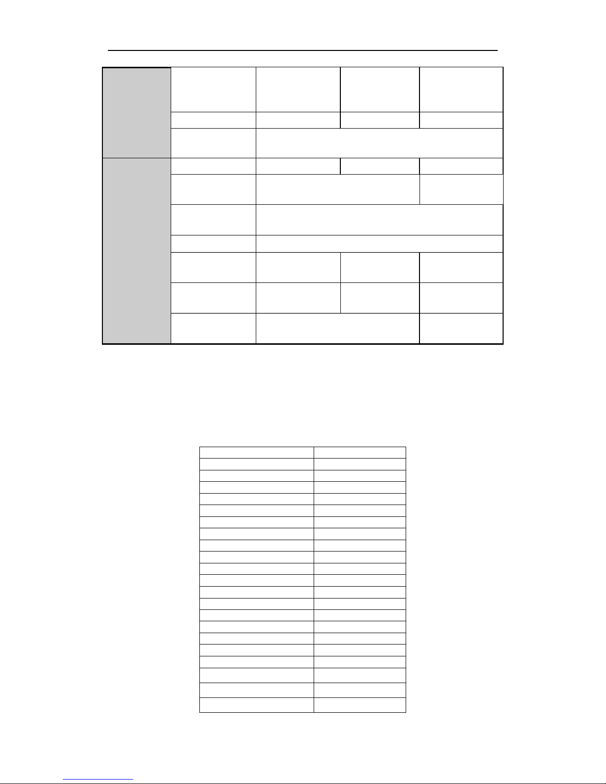
The following chart shows an estimation of storage space used based on recording at one channel for an hour at a
fixed bit rate.
Bit Rate
Storage Used
96K
42M
128K
56M
160K
70M
192K
84M
224K
98M
256K
112M
320K
140M
384K
168M
448K
196M
512K
225M
640K
281M
768K
337M
896K
393M
1024K
450M
1280K
562M
1536K
675M
1792K
787M
2048K
900M
4096K
1.8G
8192K
3.6G
16384K
7.2G
Page 29

28
Note:
Supplied values for storage space used are just for reference. The storage values in the chart are estimated by
formulas and may have some deviation from actual value.
Page 30

29
For further information, including full user and installation manual, and technical support please visit:
www.hills.com.au/videosecurity
Page 31

30
 Loading...