

Hills NVR-CH4, NVR-CH8, NVR-CH16 Quick Manual

Network Video Recorder
NVR-CH4
NVR-CH8
NVR-CH16
Quick Guide

1
TABLE OF CONTENTS
Overview ......................................................................................................................................................... 2
Front Panel ................................................................................................................................................. 2
Rear Panel .................................................................................................................................................. 8
Peripheral Connections ................................................................................................................................. 10
Wiring of Alarm Input .............................................................................................................................. 10
Wiring of Alarm Output ........................................................................................................................... 10
Using of Alarm Connectors ...................................................................................................................... 10
Accessing via Local Display........................................................................................................................... 11
Menu Structure ......................................................................................................................................... 11
Startup and Shutdown .............................................................................................................................. 12
Live View ................................................................................................................................................. 12
Adding IP Cameras .................................................................................................................................. 12
Recording ................................................................................................................................................. 14
Instant Recording ............................................................................................................................. 14
All-day Recording ............................................................................................................................ 15
Playback ................................................................................................................................................... 15
Backup ..................................................................................................................................................... 17
Accessing via Web Browser ........................................................................................................................... 20
Logging In ................................................................................................................................................ 20
Live View ................................................................................................................................................. 20
Recording ................................................................................................................................................. 22
Playback ................................................................................................................................................... 23
Log ........................................................................................................................................................... 24
Specifications ....................................................................................................... Error! Bookmark not defined.
HDD Storage Calculation Chart ............................................................................................................... 27

2
Overview
Front Panel
NVR-4Channel (NVR-CH4)
No.
Name
Description
1
Status
Indicator
Power
Power indicator turns yellow when system is running.
Status
Status indicator blinks red when data is being read from or written
to HDD.
Tx/Rx
Tx/Rx indictor blinks yellow when network connection is
functioning properly.
2
Control
Buttons
DIRECTION
In menu mode, the direction buttons are used to navigate between
different fields and items and select setting parameters.
In playback mode, the Up and Down buttons are used to speed up
and slow down record playing, and the Left and Right buttons are
used to move the recording 30s forward or backward.
In the image setting interface, the up and down button can adjust
the level bar of the image parameters.
In live view mode, these buttons can be used to switch channels.
ENTER
The Enter button is used to confirm selection in menu mode; or
used to check checkbox fields and ON/OFF switch.
In playback mode, it can be used to play or pause video.
In single-frame play mode, pressing the Enter button will play the
video by a single frame.
In auto sequence view mode, the buttons can be used to pause or
resume auto sequence.
3
Composite
Keys
SHIFT
Switch between the numeric or letter input and functions of the
composite keys. (Input letter or numbers when the light is out;
Realize functions when the light is red.)
1/MENU
Enter numeral “1”;
Access the main menu interface.
2/ABC/F1
Enter numeral “2”;
Enter letters “ABC”;
The F1 button when used in a list field will select all items in the
list.
In PTZ Control mode, it will turn on/off PTZ light and when the
image is zoomed in, the key is used to zoom out.
3/DEF/F2
Enter numeral “3”;
Enter letters “DEF”;
Overview 1

3
The F2 button is used to change the tab pages.
In PTZ control mode, it zooms in the image.
4/GHI/ESC
Enter numeral “4”;
Enter letters “GHI”;
Exit and back to the previous menu.
5/JKL/EDIT
Enter numeral “5”;
Enter letters “JKL”;
Delete characters before cursor;
Check the checkbox and select the ON/OFF switch;
Start/stop record clipping in playback.
6/MNO/PLAY
Enter numeral “6”;
Enter letters “MNO”;
Playback, for direct access to playback interface.
7/PQRS/REC
Enter numeral “7”;
Enter letters “PQRS”;
Open the manual record interface.
8/TUV/PTZ
Enter numeral “8”;
Enter letters “TUV”;
Access PTZ control interface.
9/WXYZ/PREV
Enter numeral “9”;
Enter letters “WXYZ”;
Multi-channel display in live view.
0/A
Enter numeral “0”;
Shift the input methods in the editing text field. (Upper and
lowercase, alphabet, symbols or numeric input).
Double press the button to switch the main and auxiliary output.
4
USB Interfaces
Universal Serial Bus (USB) ports for additional devices such as
USB mouse and USB Hard Disk Drive (HDD)
NVR-8Channel (NVR-CH8)
No.
Name
Function Description
1
Status
Indicators
POWER
Turns green when NVR is powered up.
READY
The LED is green when the device is running normally.
STATUS
The light is green when the IR remote control is enabled;
The light is red when the function of the composite keys (SHIFT)
are used;
The light is out when none of the above conditions are met.
ALARM
The light is red when there is an alarm occurring.
HDD
Blinks red when HDD is reading/writing.

4
No.
Name
Function Description
Tx/Rx
Blinks green when network connection is functioning normally.
2
Control
Buttons
DIRECTION
In menu mode, the direction buttons are used to navigate between
different fields and items and select setting parameters.
In playback mode, the Up and Down buttons are used to speed up
and slow down record playing, and the Left and Right buttons are
used to move the recording 30s forwards or backwards.
In the image setting interface, the up and down button can adjust
the level bar of the image parameters.
In live view mode, these buttons can be used to switch channels.
ENTER
The Enter button is used to confirm selection in menu mode; or
used to check checkbox fields and ON/OFF switch.
In playback mode, it can be used to play or pause video.
In single-frame play mode, pressing the Enter button will play the
video by a single frame.
In auto sequence view mode, the buttons can be used to pause or
resume auto sequence.
3
Composite
Keys
SHIFT
Switch between the numeric or letter input and functions of the
composite keys. (Input letter or numbers when the light is out;
Realize functions when the light is red.)
1/MENU
Enter numeral “1”;
Access the main menu interface.
2/ABC/F1
Enter numeral “2”;
Enter letters “ABC”;
The F1 button when used in a list field will select all items in the
list.
In PTZ Control mode, it will turn on/off PTZ light and when the
image is zoomed in, the key is used to zoom out.
3/DEF/F2
Enter numeral “3”;
Enter letters “DEF”;
The F2 button is used to change the tab pages.
In PTZ control mode, it zooms in the image.
4/GHI/ESC
Enter numeral “4”;
Enter letters “GHI”;
Exit and back to the previous menu.
5/JKL/EDIT
Enter numeral “5”;
Enter letters “JKL”;
Delete characters before cursor;
Check the checkbox and select the ON/OFF switch;
Start/stop record clipping in playback.
6/MNO/PLAY
Enter numeral “6”;
Enter letters “MNO”;
Playback, for direct access to playback interface.
7/PQRS/REC
Enter numeral “7”;
Enter letters “PQRS”;

5
No.
Name
Function Description
Open the manual record interface.
8/TUV/PTZ
Enter numeral “8”;
Enter letters “TUV”;
Access PTZ control interface.
9/WXYZ/PRE
V
Enter numeral “9”;
Enter letters “WXYZ”;
Multi-channel display in live view.
0/A
Enter numeral “0”;
Shift the input methods in the editing text field. (Upper and
lowercase, alphabet, symbols or numeric input).
Double press the button to switch the main and auxiliary output.
4
USB Interfaces
Universal Serial Bus (USB) ports for additional devices such as
USB mouse and USB Hard Disk Drive (HDD).
NVR-16Channel (NVR-CH16)
No.
Name
Function Description
1
Status
Indicators
POWER
Turns green when NVR is powered up.
READY
The LED is green when the device is running normally.
STATUS
The light is green when the IR remote control is enabled;
The light is red when the function of the composite keys (SHIFT)
are used;
The light is out when none of the above condition is met.
ALARM
The light is red when there is an alarm occurring.
HDD
Blinks red when HDD is reading/writing.
Tx/Rx
Blinks green when network connection is functioning normally.
2
DVD-R/W
Slot for DVD-R/W.
3
Control
Buttons
DIRECTION
In menu mode, the direction buttons are used to navigate between
different fields and items and select setting parameters.
In playback mode, the Up and Down buttons are used to speed up
and slow down record playing, and the Left and Right buttons are
used to move the recording 30s forwards or backwards.
In the image setting interface, the up and down button can adjust
the level bar of the image parameters.

6
No.
Name
Function Description
In live view mode, these buttons can be used to switch channels.
ENTER
The Enter button is used to confirm selection in menu mode; or
used to check checkbox fields and ON/OFF switch.
In playback mode, it can be used to play or pause video.
In single-frame play mode, pressing the Enter button will play the
video by a single frame.
In auto sequence view mode, the buttons can be used to pause or
resume auto sequence.
4
Composite
Keys
SHIFT
Switch between the numeric or letter input and functions of the
composite keys. (Input letter or numbers when the light is out;
Realize functions when the light is red.)
1/MENU
Enter numeral “1”;
Access the main menu interface.
2/ABC/F1
Enter numeral “2”;
Enter letters “ABC”;
The F1 button when used in a list field will select all items in the
list.
In PTZ Control mode, it will turn on/off PTZ light and when the
image is zoomed in, the key is used to zoom out.
3/DEF/F2
Enter numeral “3”;
Enter letters “DEF”;
The F2 button is used to change the tab pages.
In PTZ control mode, it zooms in the image.
4/GHI/ESC
Enter numeral “4”;
Enter letters “GHI”;
Exit and back to the previous menu.
5/JKL/EDIT
Enter numeral “5”;
Enter letters “JKL”;
Delete characters before cursor;
Check the checkbox and select the ON/OFF switch;
Start/stop record clipping in playback.
6/MNO/PLAY
Enter numeral “6”;
Enter letters “MNO”;
Playback, for direct access to playback interface.
7/PQRS/REC
Enter numeral “7”;
Enter letters “PQRS”;
Open the manual record interface.
8/TUV/PTZ
Enter numeral “8”;
Enter letters “TUV”;
Access PTZ control interface.
9/WXYZ/PRE
V
Enter numeral “9”;
Enter letters “WXYZ”;
Multi-channel display in live view.
0/A
Enter numeral “0”;
7
No.
Name
Function Description
Shift the input methods in the editing text field. (Upper and
lowercase, alphabet, symbols or numeric input).
Double press the button to switch the main and auxiliary output.
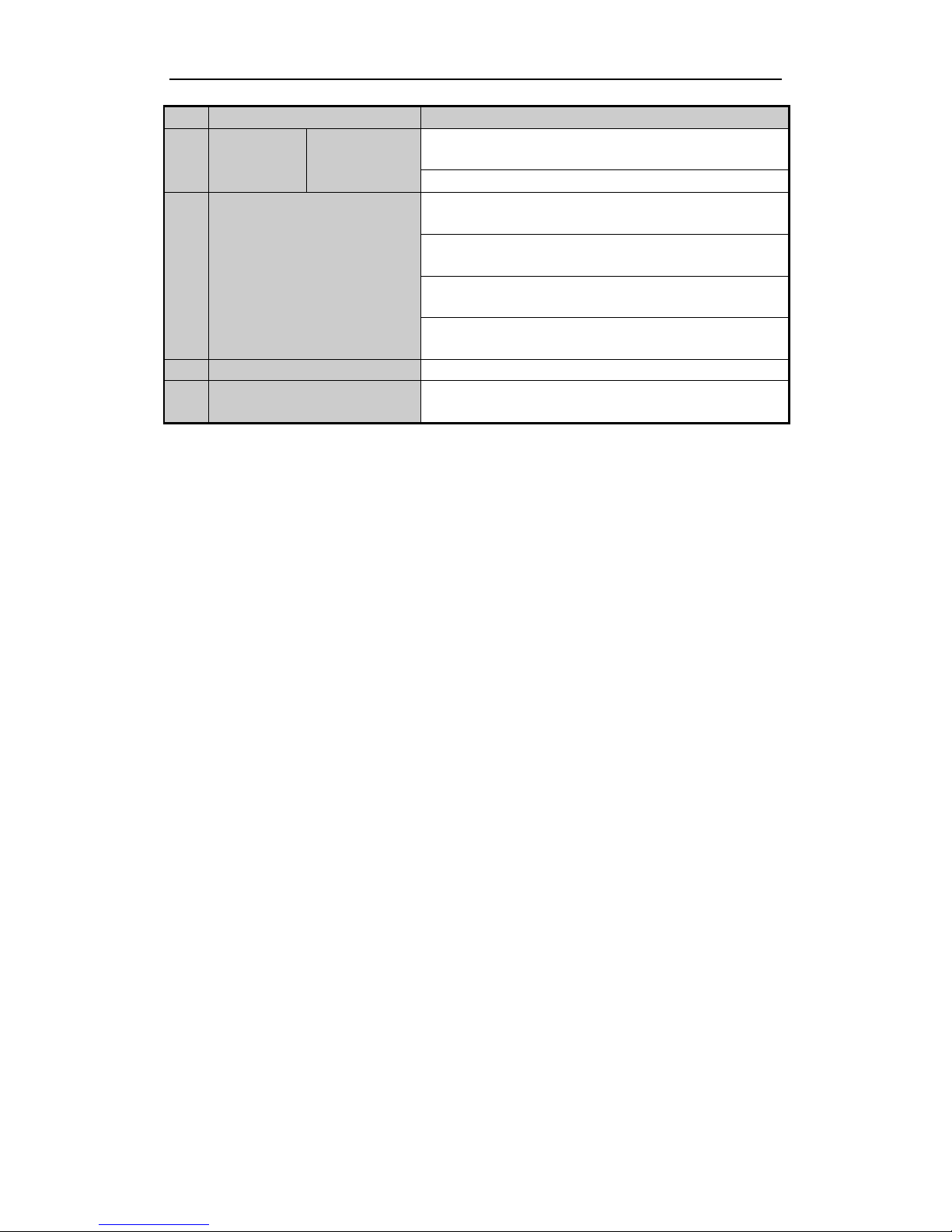
5
JOG SHUTTLE Control
Move the active selection in a menu. It will move the selection up
and down.
In Live View mode, it can be used to cycle through different
channels.
In the Playback mode, it can be used to jump 30s
forward/backward in video files.
In PTZ control mode, it can control the movement of the PTZ
camera. 6 POWER ON/OFF
Power on/off switch.
7
USB Interfaces
Universal Serial Bus (USB) ports for additional devices such as
USB mouse and USB Hard Disk Drive (HDD).

8
Rear Panel
NVR-4Channel (NVR-CH4)
NVR-8Channel (NVR-CH8)
No.
Item
Description
1
Power Supply
48V DC power supply for NVR-CH4 and AC 100~240V for
NVR-CH8.
2
Audio In
RCA connector for audio input.
3
HDMI Interface
HDMI video output connector.
4
LAN Network Interface
1 10 /100 /1000 Mbps self-adaptive Ethernet interface
5
Audio Out
RCA connector for audio output.
6
VGA Interface
DB9 connector for VGA output. Display local video output and menu.
7
USB Interface
Universal Serial Bus (USB) ports for additional devices such as USB
mouse and USB Hard Disk Drive (HDD).
8
Ground
Ground (needs to be connected when NVR starts up).
9
Power Switch
Switch for turning on/off the device.
10
Network Interfaces with
PoE function
Network interfaces for the cameras and power over Ethernet.
9
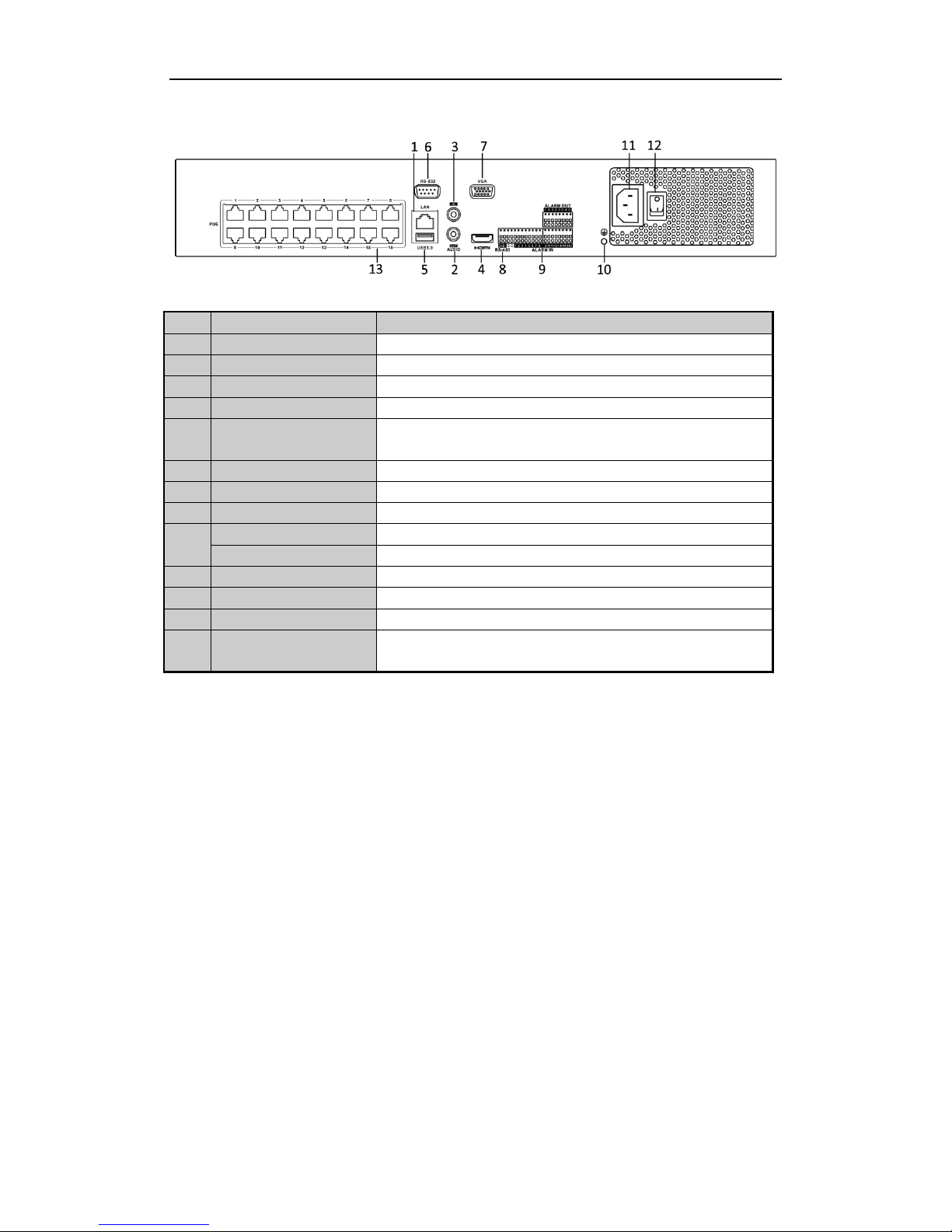
NVR-16Channel (NVR-CH16)
No.
Item
Description
1
LAN Interface
1 network interface
2
AUDIO OUT
RCA connector for audio output.
3
LINE IN
RCA connector for audio input.
4
HDMI
HDMI video output connector.
5
USB 3.0 interface
Universal Serial Bus (USB) ports for additional devices such as USB
mouse and USB Hard Disk Drive (HDD).
6
RS-232 Interface
Connector for RS-232 devices.
7
VGA
DB9 connector for VGA output. Display local video output and menu.
8
RS-485 Interface
Half-duplex connector for RS-485 devices.
9
ALARM IN
Connector for alarm input.
ALARM OUT
Connector for alarm output.
10
GROUND
Ground (needs to be connected when NVR starts up).
11
AC 100V ~ 240V
100V ~ 240V AC power supply.
12
Power Switch
Switch for turning on/off the device.
13
Network Interfaces with
PoE function
Network interfaces for the cameras and power over Ethernet.
 Loading...