

Hills NVC-BM1, NVC-DT1, NVC-DM1, NVC-DF1 Installation Manual

1
Network Camera Installation manual
NVC-BM1
NVC-DF1
NVC-DT1
NVC-DM1
V1.1

2
Congratulations on the purchase of your Hills Professional CCTV solution.
It’s important that you read this installation guide thoroughly before installation.
Thank you for choosing Hills.
Part no.
Model no.
Type
Model
S47092
NVC-DT1
Eyeball Dome camera
3MP IR Eyeball Camera (4mm)
S47091
NVC-DF1
Dome camera
3MP IR Dome Camera (4mm)
S47090
NVC-BM1
Bullet Camera
3MP IR Bullet Camera (4mm)
S47093
NVC-DM1
Mini Dome Camera
3MP IR Mini Dome Camera (2.8mm)
Checklist before you start:
All carton contents present and are in good conditions.
Ensure power supplies are off during installation.
Power supply voltage rating as specified in product specification.
Installation environment match is as specified.
Contact your dealer if product does not function properly. Do not attempt to repair yourself.
Wall or mounting platform is strong enough to withstand three times the weight of the camera.
For further information, including datasheets, FAQ and technical support please visit:
www.hills.com.au/videosecurity

3
Table of Contents:
1 NVC-DT1 - 3MP IR Eyeball Camera (4mm) --------------------------------------------------------- 4
1.1 Overview --------------------------------------------------------- 4
1.2 Installation --------------------------------------------------------- 5
2 NVC-DF1 - 3MP IR Dome Camera (4mm) --------------------------------------------------------- 10
2.1 Overview --------------------------------------------------------- 10
2.2 Installation --------------------------------------------------------- 11
3 NVC-BM1 - 3MP IR Bullet Camera (4mm) --------------------------------------------------------- 14
3.1 Overview --------------------------------------------------------- 14
3.2 Installation --------------------------------------------------------- 15
4 NVC-DM1 - 3MP IR Mini Dome Camera (4mm) ----------------------------------------------------- 17
4.1 Overview --------------------------------------------------------- 17
4.2 Installation --------------------------------------------------------- 18

4
1.1 Overview
Figure 1-1 Product Structure Diagram
Table 1-1 Description
NO.
Description
1
Ethernet interface, PoE
2
Power Cable, 12V DC
3
Trim Ring
4
Camera
Note:
This camera supports Power over Ethernet (PoE), and the standard power supply is 12V DC.
If a power adaptor is used please make sure that it is compatible with the camera.
NVC-DT1 - 3MP IR Eyeball Camera (4mm)
1

5
1.2 Installation
Before you start, please verify the package contents are correct by checking the items against the
carton content list in the Quick Guide, and make sure all the components are included.
Note:
Please make sure that the wall is strong enough to withstand three times the weight of the
camera.
Wall mounting is recommended for this camera.
The wall must be strong enough to withstand more than three times the weight of the
camera.
Steps:
1. Dissembling the Trim Ring
1) Rotate the trim ring counterclockwise to remove it from the camera.
Figure 1-2 Dissembling the Trim Ring
2. Drill the Holes
1) Attach the supplied drill template to the position where you want to fix the camera.
2) Drill the screw holes and the cable hole on the ceiling according to the drill template.
Figure 1-3 The Drill Template
6
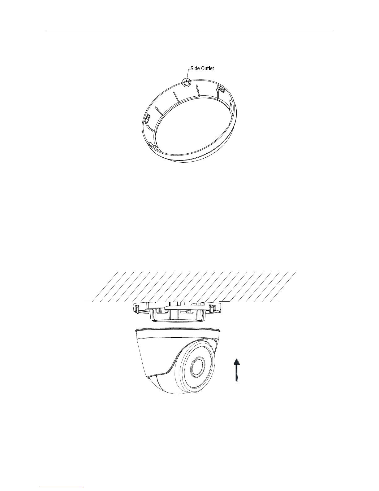
There are two cable outlet methods. One is to route the cables through the cable hole, and the
other is to route the cables through the side outlet shown below.
Figure 1-4 Side Outlet
Note:
Three side outlets on the enclosure are selectable, which makes routing the cables easier instead of
drilling a cable hole on the ceiling. Use a plier to remove the plastic and route the cables through
the hole.
3. Install the Camera
1). Connect the corresponding power/video cables.
2). Insert the supplied screws to the screw holes.
3). Tighten the screws to secure the camera to the ceiling.
Figure 1-5 Secure the Camera to the Ceiling
 Loading...