

Hills FD52007 Product Manual

the
retracting
clothesline
product
manual
5-line

32
Congratulations
Congratulations on the purchase of your new
Hills Retracting Clothesline which will bring
you many years of trouble free and efficient
outdoor drying.
It’s important that you read this Product Manual
thoroughly before installation to benefit from
the design features and enjoy safe use of this
product.
Thank you for choosing Hills.
Warning
• Do not allow children or pets to swing on the
Clothesline or items of laundry.
• Do not use for any purpose other than to
hang and dry washing.
• Do not use your Clothesline if parts are worn
or damaged.
• Do not operate the locking lever when the
arm is located in the cabinet.
• Do not release the locking mechanism when
there are clothes attached to the lines.
• Do not allow the arm and lines to retract
uncontrolled as this may lead to personal
injury or property damage. Hold the arm
securely and walk it back to the cabinet.
Patents and Registered Designs apply to
this product.
Please retain this Product Manual. Record the following
information for future reference.
Product Number (printed on carton):
Date of purchase:
Name and location of store:
Introduction
Made in China
Designed and tested under a
Quality System that meets Hills’
demanding quality specifications.
®
Carton contents
Part name Qty.
Retracting line cabinet 1
Receiving bracket 1
Optional Post Mounting Kits
If you choose to mount your Retracting
Clothesline cabinet or receiving bracket on
posts, the following products are available.
Post Kits:
100550 – Hills Retracting Clothesline Post Kit
Mount Bar Kits:
100548 – Hills Retracting Clothesline Mount Bar
Mounting Options
Mounting Options
Determine which of the four mounting options most suits your requirements.
Wall to Wall
Wall to Post
Requires:
1 Post Kit
Post to Wall
Requires:
1 Post Kit
1 Mount Bar Kit
Post to Post
Requires:
2 Post Kits
1 Mount Bar Kit
6
A
B
C
54321 211101987
6
A
B
C
54321 211101987
6
A
B
C
54321 211101987
6
A
B
C
54321 211101987
Note: Minimum operating distance is 2.0m (6'6").
Maximum operating distance is 6.5m (21'4").
54
Site Selection
Installation Height
Step 1 – Select a suitable location
1.1 Select a suitable location for either wall or post mounted installations.
1.2 This product has been designed to mount and operate between 2.0m (6'6") and
6.5m (21'4").
1.3 Always leave approximately 1.5m (5') clearance each side of the line and any wall
fence/shed etc.
Note: This product must only be installed on sound structural walls. May not be
suitable for mounting on timber or cladded dwelling unless the cabinet or receiving
bracket is mounted directly to vertical studs – NOT TO CLADDING.
Do not mount directly onto cladding materials.
If you have any doubt, contact your local hardware store or installer.
1.5m (5') clearance from
obstructions either side
Receiving bracket
Cabinet
Mounting surface
Arm
Mounting surface
2.0m (6'6") minimum to 6.5m
(21'4") maximum
6
A
B
C
54321 211101987
6
A
B
C
54321 211101987
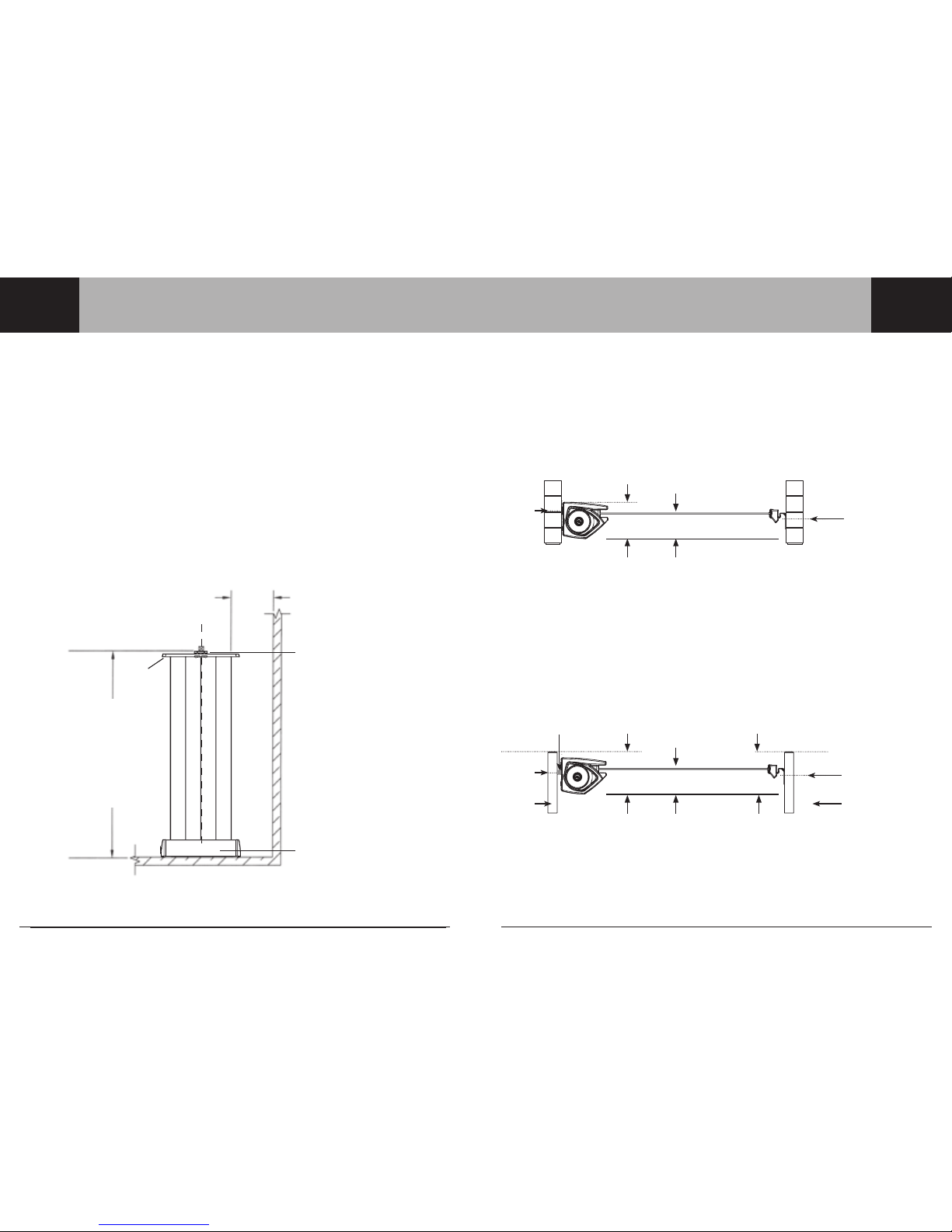
Cabinet
fasteners
Cabinet
fasteners
User’s
head height
50mm (2")
User’s
head height
50mm (2")
60mm
(2¼")
115mm
(4½")
125mm
(5")
Receiving
bracket
fasteners
Receiving
bracket
fasteners
Note: The receiving bracket should
be located at a height to ensure the
clothesline is close to horizontal.
Location of receiving
bracket fasteners are
approximately 25mm (1")
above user's head height
(when installed on level
ground).
For post mounting a
receiving bracket, the
top of the post should be
approximately 125mm
(5") above user's head
height (when installed on
level ground).
Location of cabinet
fasteners are
approximately 60mm
(2¼") above user's
head height.
For post mounting
a cabinet, the top of
the post should be
approximately 115mm
(4½") above user's
head height.
Mount bar
Top of post Top of post
Post kit
Note: The receiving bracket should be located at a
height to ensure the clothesline is close to horizontal.
Wall Installation
Step 2 – Recommended installation height
2.1 For all installations, we recommend the operational height for the line is approximately 50mm
(2") above the user’s head height.
2.2 For the heights and combinations of wall/post installations refer to the appropriate details
below.
Post Installation
Cabinet
Cabinet
Receiving bracket
Receiving bracket
Post kit

76
Installation
Installation
Drill 2 holes using
masonry drill
Product centre line
30mm
Mount hole centres
Top of
product
Product centre line
Step 3 – Mounting your cabinet to a wall
3.1 Prepare your cabinet location
Determine the best location for the installation of your product (refer to page 4).
Mark out a centre line for your product within your allocated site.
3.2 Ensure that either side of this centre line and the area where the cabinet is to be installed on
the wall is free from pipes and other obstructions (Fig. 1).
3.3 Mark the cabinet mount centres on the wall at the desired installation height (refer to page 5
and the table below).
Centres
(mm)
Centres
(inch)
705 27¾
Fig. 1
3.4 Drill holes in wall
Masonry fasteners are not included with this product. When attaching to a sound masonry
wall, we recommend using masonry sleeve (hex head) anchors (diameter 8mm x 45mm).
3.5 If you are using these fasteners, drill an 8mm (5/16") hole using a masonry drill (Fig 2).
Note: If you are mounting to a different wall type, consult your hardware store for advice on
the appropriate fasteners to use.
Fig. 2
Mount
centres
Ensure surrounding
area is free from
obstructions
‘Mount Hole Centres’
2.0m (6'6") to
6.5m (21’4")
Step 3 (continued) – Mounting your cabinet to a wall
3.6 Remove the arm from the cabinet by pulling on the two blue end caps. Remove the end
covers only from the cabinet by unscrewing the two screws (Fig 3).
3.7 Locate the cabinet on the wall, ensure cabinet is level. Using appropriate wall fasteners
secure cabinet to the wall.
3.8 Reattach the cabinet end covers and secure with the screws. Refit arm into cabinet.
Fig. 3
Masonry anchor
(Not included)
Masonry anchor
(Not included)
End cover
End cover screw
Arm
End cover screw
Blue end cap
 Loading...