


S I N G L E - D E C K I S L A N D M E R C H A N D I S E R I N S TA L L AT I O N & O P E R AT I O N S M A N U A L
O W I Z - O W E Z
O W I Z V - O W E Z V
TABLE OF CONTENTS
GENERAL INFORMATION ...................................... 2
INSTALLATION & TRIM OUT .............................. 3–4
CONNECTIONS & PIPING ...................................... 5
PRE-POWER CHECKLIST ....................................... 6
To ensure proper functionality and optimum performance, it is strongly recommended that Hillphoenix display cases be installed/serviced by
qualied technicians who have experience working with commercial refrigerated display merchandisers and storage cabinets. For a list of
Hillphoenix-authorized installation/service contractors, please visit our Web site at www.hillphoenix.com.
COMPONENT
LIGHTING SYSTEMS .......................................... 7–8
AIR QUALITY CONTROL ........................................ 9
FANS & CASE CLEANING .................................... 10
APPENDIX ............................................................. 11
P080658A
V1.07
03/14

ii REVISION HISTORY
REV. DATE CHANGE DESCRIPTION AUTHOR
V1.00 02/21/12 Initial manual release (new format) B. Moody
V1.01 04/30/12 Removed Dual Temp (Fans Off) wiring diagram (Appendix E) B. Moody
V1.02 07/02/12 Correct TOC errors B. Moody
V1.03 08/03/12 Updated Wiring Diagrams (Appendix E) B. Moody
V1.04 10/15/12 Updated Electrical Data (Appendices A–D) B. Moody
V1.05 12/19/12 Updated Electrical Data (Appendices A–D) B. Moody
V1.06 07/03/13 Added Glycol notice to Important Notices section
Added Parts List (Appendix H)
V1.07 03/14/14 Added Clearvoyent logos to cover page
Updated page headers
Added Parts logo to General Information page
Updated Important Notices section
Updated Connections & Piping section
Added Lighting Systems section
Updated Air Quality Control page
Added Fresh Thinking/Responsible Solutions logo to back page
B. Moody
B. Moody
Copyright © 2014 by Hill PHOENIX
All rights reserved. No part of this document may reproduced or transmitted in any form or by any means—electronic or
mechanical, including photocopying or recording; or any other information storage and retrieval system—without express
written permission from Hill PHOENIX.

IMPORTANT NOTICES iii
PRECAUTIONARY NOTICES
At Hillphoenix®, the safety of our customers and employees—as well as the ongoing performance of our
products—are top priorities. To that end, we designate
important information in all Hillphoenix installation and operations handbooks with an accompanying alert symbol.
All of these notices are meant to provide information about
potential dangers to personal health and safety—as well as
risks of case damage—if the instructions are not carefully
followed.
ATTENTION!
Indicates important information that is critical to proper case performance.
CAUTION!
Indicates the potential threat of injury if all
instructions are not followed carefully.
DANGER!
Indicates an immediate threat of serious
injury or death if all instructions are not followed carefully.
used on a display case with a shelf lighting system, then
Hillphoenix shall not be subject to any obligations or liabilities (whether arising out of breach of contract, warranty,
tort [including negligence], strict liability or other theories
of law) directly or indirectly resulting from, arising out of or
related to such installation or use, including, without limitation, any personal injury, death or property damage resulting from an electrical failure, re, electric shock, or mold.
P079211M, REVO
R-744 (CO2) NOTICE
For Systems Utilizing R-744 (CO2) Refrigerant
For refrigeration units that utilize R-744 (CO2), pressure relief and pressure-regulating relief valves may need to be
installed based on the system capacity. The valves need
to be located such that no stop valve is positioned between
the relief valves and the parts or section of the system being protected.
When de-energizing refrigeration units containing R-744
(CO2), venting of the R-744 (CO2) refrigerant may occur
through the pressure regulating relief valves. These valves
are located on the refrigeration system and not on the case
model. If venting does occur, the valve must not be defeated, capped, or altered by any means.
SERVICE NOTICE
To ensure optimum case performance, we strongly recommended that Hillphoenix display cases be installed and
serviced by qualied technicians who have experience
working with commercial refrigerated display merchandisers and storage cabinets. For a list of Hillphoenix-authorized installation and service contractors, please visit our
Web site: www.hillphoenix.com
LIABILITY NOTICE
For Cases with Shelf Lighting Systems
Hillphoenix shelf lighting systems—as well as display cases with shelf lighting systems—are not designed to withstand direct or indirect exposure to water or other liquids.
The use of a misting system or water hose on a display
case with a shelf lighting system, resulting in the direct or
indirect exposure of the lighting system to water, can lead
to a number of serious issues (including, without limitation,
electrical failures, re, electric shock, and mold) in turn resulting in personal injury, death, sickness, and/or serious
property damage (including, without limitation, to the display itself, to the location where the display is situated [e.g.,
store] and to any surrounding property).
Do not use misting systems, water hoses or other devices
that spray liquids in Hillphoenix display cases with lighted
shelves. If a misting system or water hose is installed or
GLYCOL NOTICE
For Systems Utilizing Glycol Refrigerant
Use of glycol as a secondary refrigerant must be carried
out in accordance with the instructions and procedures set
forth in the Hillphoenix Second Nature Medium Temperature Secondary Refrigeration Installation Manual, available
online for download here: http://goo.gl/JIWd77
Additionally, Hillphoenix uses and recommends Dow glycol-based coolants, which contain specially formulated
industrial inhibitors that help to prevent corrosion in our
display cases. Over time, the effectiveness of these inhibitors deteriorates, increasing the chance for corrosion.
We recommend testing of glycol solutions annually through
the Dow lab. The service is free for systems containing
over 250 gallons of glycol coolants, while the cost is approximately $100 for smaller systems. For more information, see Dow’s DOWFROST and DOWFROST HD Guide,
available online for download here: http://goo.gl/v6i1iQ
CAUTION!
Under no circumstance should any component be replaced or added without
consulting Hillphoenix Field Service Engineering. Utilizing improper components
may result in serious injury to persons or
damage to the refrigeration system.

2 GENERAL INFORMATION
Thank you for choosing Hillphoenix display cases for your food merchandising needs. This handbook contains important
technical information and will assist you with the installation and operation of your new display cases. By closely following
the instructions, you can expect attractive fit and finish, peak performance, and long case life.
We are always interested in your suggestions for improvements to Hillphoenix products and accessories—case design,
technical documents, etc. Please feel free to contact our Marketing Services group at the toll-free number listed below.
Thank you for choosing Hillphoenix, and we wish you the very best in outstanding food merchandising.
CASE MODELS
OWIZ, OWEZ, OWIZV, OWEZV single-deck island merchandisers.
OPERATING DATA & DIMENSIONAL DRAWINGS
Operating data and dimensional drawings for the cases
listed in this manual can be found in Appendices A–D.
STORE CONDITIONS
Hillphoenix cases are designed to operate in an air-conditioned store that maintains a 75°F (24°C) store temperature and 55% (max) relative humidity (CRMA conditions).
Case operation will be adversely affected by exposure to
excessively high ambient temperatures and/or humidity.
REFRIGERATION SYSTEM OPERATION
Air-cooled condensing units require adequate ventilation
for efficient performance. Machine-room temperatures
must be maintained at a minimum of 65°F in winter and a
maximum of 95°F in summer. Minimum condensing temperatures should be no less than 70°F.
RECEIVING CASES
Examine fixtures carefully and in the event of shipping
damage and/or shortages, please contact the Service
Parts Department at 1-800-283-1109.
SERVICE/TECHNICAL SUPPORT
For service or technical questions, please contact our
Case Division Customer Service Department at 1-800283-1109. For questions regarding our refrigeration systems or electrical distribution centers, please contact our
Systems Division Customer Service Department at 1-770-
388-0706.
PARTS ORDERING
If you need to contact Hillphoenix regarding specific fixtures or parts, please call 1-800-283-1109 and ask for a
Service Parts Representative. Provide the following information about the part you are ordering:
• Model number and serial number* of the case for which
the part is intended.
• Length of the part (if applicable).
• Color of part (if painted) or color of polymer part.
• Whether part is for left- or right-hand application.
• Quantity
*Serial plate is located inside the case on the bottom-right side.
If the parts are to be returned for credit, ask the Parts
Department to furnish you with a Return Material
Authorization Number.
CASE DAMAGE
Claims for obvious damage must be 1) noted on either the
freight bill or the express receipt and 2) signed by the carrier's agent; otherwise, the carrier may refuse the claim. If
damage becomes apparent after the equipment is
unpacked, retain all packing materials and submit a written
request to the carrier for inspection within 14 days of
receipt of the equipment.
LOST/MISSING ITEMS
Hillphoenix equipment is carefully inspected before shipping to insure the highest level of quality. Any claim for
lost/missing items must be made to Hillphoenix within 48
hours of receipt of the equipment.
See Appendix H for a detailed parts list and illustration.
Hillphoenix
1925 Ruffin Mill Rd.
Colonial Heights, VA 23834
Mon.-Fri. (8 a.m. to 5 p.m. EST)
Tel: 1-800-283-1109
Fax: 804-526-7450
Web site: www.hillphoenix.com

INSTALLATION & TRIM OUT 3
FLOOR PREP
1. Ask the general contractor if your current copy of the
building dimensions are the most recently issued. Also,
ask for the points of reference from which you should
take dimensions to locate the cases.
2. Using chalk lines or a laser transit, mark the oor
where the cases are to be located for the entire lineup.
The lines should coincide with the outside edges of the
case feet.
3. Leveling is necessary to ensure proper case alignment
and to avoid potential case damage. Locate the highest point on the positioning lines as a reference for
determining the proper height of the shim-pack levelers. A laser transit is recommended for precision and
requires just one person.
4. Locate basehorse positions along the chalk lines. Spot
properly leveled shim packs at each basehorse location.
LINE-UP & INSTALLATION
Single Case
1. Roll the case into position, leaving a minimum of 2” between the wall and back of case. Using a “J” bar, raise
the end of the case (under cross support), remove the
caster assembly (Fig. 1) and lower the basehorse on to
the shim packs. Repeat on the other end of the case.
2. Once the basehorse is properly placed on the shim
packs, check the vertical plumb of the case by placing
a bubble level on the shelf standard. Add/remove shim
packs as needed. For the horizontal level, repeat this
process after placing the bubble level on the front sill.
Multi-Case
1. Remove any shelves (discard the shelf clips) and/or
loose items (e.g. shipping braces, mirror assemblies,
etc) from the cases that may interfere with case joining. Keep all loose items as they will be used later in
the installation process.
2. Follow the single-case installation instructions for the
rst case, then position the next case in the line-up approximately 3’ away. Remove the casters on the end
that is closest to the rst case.
3. Apply the foam tape gasket (supplied) and a bead of
butyl or silicone sealant to the end of the rst case (Fig.
2). From the opposite end, push the second case to
a position that is approximately 6” from the rst case,
then remove the remaining casters and position case
on the shim packs.
4. Push the cases tightly together, then lightly bolt them
together through the holes that are provided (Fig. 2).
Tighten all the joining bolts until all margins are equal.
Be careful not to over tighten.
5. Repeat steps 3-6 of this sequence for all remaining
cases. Be certain to properly level all cases.
6. See Appendix G for seismic bracket installation instructions.
TRIM OUT
COTTER
PIN
CASTER
Fig. 1 Removing the casters is an easy process. Simply flatten and
remove the cotter pins that are holding the casters in place. Then
lift the case with a “J” bar and slide the caster assemblies out. The
dismantled casters can now be discarded.
CAUTION!
Be certain that your hands and feet are
out of the way before lowering the case
after the removal of the casters. Failure
to do so may result in serious injury.
1.
If master bumpers are included, slide master bumper
joint trim in between adjoining master bumpers.
2. Slide the master bumpers left or right (after loosening
or removing screws) to close the seams as required,
working outwards from the center of the line-up to the
ends.
3. Close the seam where the bumper joins the case end.
The bumper joint closes the seam that may develop
if the master bumper is moved away from the end to
close the case-to-case joint seam.
4. Install top sill covers over case-to-case joint seams.
The top sill joint is shipped loose with the case. Secure
with fasteners (supplied).
5. Seal the case-to-case joints with caulk (supplied), then
apply acrylic tape (supplied) over the pipe-chase seam
(Fig. 4). The tape acts as a watershed preventing water from settling in the case joint.
6. Install the front panel joint trim (ships loose).

4 INSTALLATION & TRIM OUT
ACRYLIC
TAPE
PIPE
CHASE
Fig. 2 Sealing the pipe chase
7. Attach the “J” rail with the supplied screws (Fig. 2).
8. Insert top of kickplate into the kickplate retainer. Slide
the kickplate up into the retainer, then down onto the
“J” rail (Fig. 3). Be certain that the bottom of the kickplate is tted over extruding "lip" of the "J" rail.
9. If the case is outtted with a polymer bumper, insert
the nose bumper into the open bumper channel, up
to 96 feet. Hillphoenix recommends leaving an additional 6 inches of nose bumper at the ends to allow for
shrinkage during the rst 24–48 hours following case
start-up—after sufcient time has passed, cut away the
excess bumper for nal t and nish. Be certain to use
an appropriate cutting tool (tubing- or PVC-cutter) to
ensure a smooth cut.
1. Slide kickplate UP into
kickplate retainer recess.
2. Drop the kickplate
DOWN onto the "J" rail lip.
1
KICKPLATE
2
"J" RAIL
Fig. 3 Kickplate installation
XXXX
X
XXX
X
X
X
7
XXXXX
o oooooooo
XX
XXXX
X
X
o
X
oooooooooooooooooooooooooooooooooooooooooo
o
X
o
o
X
o
X
o
X
o
X
o
X
X
X
X
X
3
o
o
o
o
o
o
o
o
o
o
o
o
o
o
o
o
o
o
o
o
o
o
o
o
o
o
X
X
X
X
X
X
X
X
X
X
o
o
o
o
o
o
o
o
o
X
X
X
X
X
X
X
X
X
1 2
o
o
o
o
o
o
o
o
o
o
X
X
X
X
X
X
X
X
5
o
o
o
o
o
o
o
o
o
o
o
o
o
X
XX
X
X
X
X
X
X
X
X
X
XX
X
ooo oooooo
XXXX
o
o
o
o
o
X
o
XX
o
o
X
o
XXXX
o
o
o
o
X
o
o
o
o
XX
o
o
o
o
o
X
o
o
X
o
o
X
o
o
X
o
XX
X
X
X
XXXX
Fig. 4 Bolt holes locations; foam gasket and sealant
= bolt holes
X
= foam tape gasket
O
= butyl or silicone sealant
NOTE: It is recommended that cases
be bolted together in the numbered
order that is indicated in the diagram.
X
ooo oooooo
o
o
o
o
o
o
o
o
o
o
o
o
o
o
o
o
X
XXXX
X
X
X
XX
X
X
6
8
4
o
o
o
o
o
o
o
o
o
o
o
o
o
o
o
o
o
o
o
o
o
o
o
o
o
o
o
o
o
o
o
o
o
o
o
o
o
o
o
o
o
o
X
X
X
X
X
X
X
XX
X
XXXXXX
XX
X
X
XX
o
o
o
o
o
o
o
o
o
o
o
o
o
o
o
o
o
o
X
o
o
o
o
o
o
o
o
X
X
X
X
X
X
X
X
X
X
XX
o oooooooo
XXX
X
X
XXX
X
XX
o
X
oooooooooooooooooooooooooooooooooooooooooo
o
X
o
X
o
X
o
X
o
X
o
o
X
o
X
o
o
X
X
X
X
X
X

ATTENTION!
Connections are illustrated in dimensional
drawings found in Appendices
REFRIGERATION
The refrigeration piping penetration is located beneath the
case in the front-right area, fully visible in front of the fan
plenum.
A–D.
CONNECTIONS & PIPING 5
If hot gas defrost is used, suction lines to each case in the
circuit should be of equal distance from the main suction
line. Expansion valves and other controls—located on the
left-hand side of the cases (both sides for the OWIZ and
OWIZV)—are accessed by lifting the two left-hand deck
pans (lifting the fan plenum is not required).
REMOVE
Fig. 5 Remove the shipping blocks
DRAIN
"P"
TRAP
Fig. 6 “P” trap; drain line
pull the bottom out, away from the case—see Trim Out
instructions on pages 4–5.
LINE
ELECTRICAL
Electrical connections are made in the continuous raceway (Fig. 7) that is located at the bottom-front of OWIZ
and OWIZV cases and all sides of the OWEZ and
OWEZV end caps. This continuous raceway helps to
easily facilitate case-to-case wiring.
Before operating the case, be certain to remove the
shipping blocks that protect the refrigeration lines during
shipping (Fig. 5). If it becomes necessary to penetrate the
case tank in any area, be certain to seal any open gaps
afterwards with canned-foam sealant and white RTV.
PLUMBING
The drain outlet is specially molded out of PVC material
and is located in the front-center of the case for convenient access. The “P” trap, furnished with the case, is
constructed of schedule 40 PVC pipe (Fig. 6). Care
should be given to ensure that all connections are watertight and sealed with the appropriate PVC or ABS cement.
The drain lines can be run left or right of the tee, with the
proper pitch to satisfy local drainage requirements. Since
the kickplate is shipped loose with the case, you should
have open access to the drain line area during installation.
If the kickplate has been installed, you will nd it easy to
remove: simply lift the kickplate up from the “J” rail and
Fig. 7 Raceway electrical wiring
For case-to-case wiring, run conduit between the junction
boxes or run wiring through the raceway. When connecting to the junction box on the bottom-left side of the case,
eld wiring should exit box from the right side (furthest
away from case wiring) to allow more room inside for
wiring connections. For more detailed electrical wiring
information, see Appendix E.
ATTENTION!
If brazing is necessary, place wet rags
around the area to avoid tank damage.

6 PRE-POWER CHECKLIST
Before powering-up the case, be certain that all of the steps listed below
have been completed to ensure proper case functionality, safety and compliance with warranty terms.
Have you thoroughly examined the case for shipping damage? (see
pg. 2)
Have you removed and discarded the casters? (see pg. 3)
Have you checked the vertical plumb of the case? The horizontal
level? (see pg. 3)
Have you applied the foam tape gasket and sealant between adjoining
cases? (see pg. 3)
Have you sealed the case-to-case joints by applying caulk and acrylic
tape to the pipe-chase seam? (see pg. 4)
Have you removed the shipping blocks from the refrigeration lines?
(see pg. 5)
Have you sealed any tank penetrations? (see pg. 5)
ATTENTION!
Be certain to clear the case of any loose
packaging or case materials before energizing the case. Failure to do so may result in case damage or malfunction.
ATTENTION!
Be certain that all piping and electrical
connections comply with local codes.
ATTENTION!
Installation of 3rd-party materials may
result in diminished case performance.

LIGHTING SYSTEMS 7
DANGER!
SHOCK HAZARD
Always disconnect power to case when
servicing or cleaning. Failure to do so
may result in serious injury or death.
Hillphoenix cases may be equipped with either T-8 lights or
LED luminaires. Depending on case configuration, T-8
electronic ballasts or LED power supplies operate both the
canopy lights and shelf lights and are located in the cornice
area, above the light reflectors.
CAUTION!
During replacement of ballasts/power
supplies, always confirm that the new ballasts/power supplies are the correct
replacement parts. Failure to do so may
result in damage to the LED system or
the luminaires, leading to poor performance and increased risk of safety issues.
Both lighting systems have an ON/OFF switch that is
located in the upper left-hand corner of the lighting assembly. Once cases have been properly positioned in the
store and an electrician has connected the lighting circuit,
the lights may be turned on to verify that they are connected and functioning properly.
To ensure peak performance, it is advisable to run the
lighting systems only when the store climate control is on
and case refrigeration is started. NOTE: it is highly recommended that the ambient store temperature not exceed
80°F.
2. Attach the lamp caps and plastic shield to the new T-8
lamp.
3. Push the new T-8 lamp into place on the lamp holder. When the T-8 is properly seated, the lamp button
- which secures the T-8 to the lamp holder - will be
clearly visible through the lamp button hole (Fig. 9).
LAMP
BUTTON
Fig. 9 Align new T-8 with plug button to secure
REPLACING SHELF LED LUMINAIRES
1. Unplug the LED luminaire (Fig. 10).
2. Pinching the latching clips inward at the ends of the luminaire, rotate luminaire down at each end until hooks
are free, then remove (Fig. 11).
3. To install the new luminaire, place hook into shelf roll at
shelf front and rotate rear of luminaire toward the shelf.
4. Depress the rear clip so that luminaire can finish rotation and until clip engages the shelf bracket.
REPLACING T-8 LIGHTS
1. Simultaneously pull down at both ends of the old T-8
light to remove from the lamp holder (Fig. 8). Remove
the lamp caps and plastic shield from the old light, then
discard the light.
LAMP
HOLDER
LAMP
CAP
Fig. 8 Remove old T-8
LAMP
BUTTON
LAMP
BUTTON
HOLE
Fig. 10 Unplug the LED luminaire

8 LIGHTING SYSTEMS
Fig. 11 Remove the old LED luminaire
REPLACING NON-SHELF LED LUMINAIRES
1. Squeeze plastic clips on the four-pin connector at the
end of the luminaire, then pull free of the receptacle
(Fig. 12).
3. To install the new luminaire, simply reverse the previous steps.
ACCESSING BALLASTS/POWER SUPPLIES
Ballasts or power supplies are housed beneath the case in
the slide-out electrical tray and may be removed easily by
following these instructions:
4. Remove the lower front panel (if necessary for access
to raceway).
5. Unscrew the kickplate and lift up from the "J" rail. Pull
the bottom edge of the kickplate out and away from the
case to remove.
6. Pull out the slide-out electrical tray that is visible in the
raceway. Ballasts/power supplies will now be visible
(Fig. 14).
2. At the other end, slide the luminaire to the opening and
disengage from the metal housing slot (Fig. 13).
Fig. 12 Squeeze the latching clips and pull the luminaire free
Fig. 14 Power supply in the slide-out tray beneath the case.
Fig. 13 Slide the other end to the opening in the sheet metal
and disengage

AIR QUALITY CONTROL 9
AIR FLOW & PRODUCT LOAD
Do not overload the food product display so that it impinges
on the air ow pattern—doing so will result in diminished
performance and loss of proper temperature levels, particularly when the discharge honeycomb and return air grille
are covered. Please keep products within the load limit line
shown on the diagram below (Fig. 15).
DEFROST & TEMPERATURE CONTROLS
Hillphoenix cases utilize electric, hot gas, or timed-off
defrost. The primary components used for the defrost
cycle are the various defrost termination sensors, which
work to terminate the defrost cycle in the case. These
controls may include 1) a Klixon® thermostat, 2) a sensor
probe, or 3) a dial-type thermostat with sensor bulb (the
thermostat will always be mounted with the electrical controls of the case, either in an electrical junction box or in the
electrical raceway, etc.
If electric defrost is used, the defrost termination sensor
will be located either behind the rear baffle or mounted to
the coil. If hot gas defrost is used, the defrost termination
sensor will be mounted to the dump line—the sensor
should always be mounted on the coil-side of the check
valve or solenoid valve. Finally, if timed-off defrost is used,
the refrigeration cycle is simply turned off by the case controls for a specified amount of time; therefore, there are
generally no active defrost components utilized.
The discharge air probe monitors the temperature of the
discharge air and may be used as the defrost termination
sensor. The probe can generally be found behind the rear
baffle, in the upper baffle, or in front of the honeycomb.
NOTE: if the discharge air probe is used for defrost termination, none of the termination sensors listed earlier will be
installed in the case.
For more detailed information on suggested defrost times
and settings, see Appendices A–D. Further adjustment
may be required depending on store conditions.
DETERMINING SUPERHEAT
To identify the correct superheat settings, complete the following steps:
1. Obtain suction pressure from the access port. Obtain
the suction line temperature from the area near the
TXV bulb at the outlet of the evaporator coil (Fig. 16).
2. Using the suction pressure reading and the Sporlan®
temperature-pressure chart (see Appendix F), convert pressure-to-temperature.
3. Finally, subtract the converted temperature reading
from the actual temperature reading. The resulting
number is the superheat setting—once this has been
determined, adjust the TXV as needed to obtain the
proper setting.
1. DISCHARGE AIR
2. LOAD LIMIT
OWIZV shown. Airflow is similar for other case models.
3. AIR CURTAIN
4. RETURN AIR
1
MODEL
2
Fig. 15 Airflow
OWIZV
SUCTION
LINE TEMP
READING
3
TXV
BULB
Fig. 16 Obtain pressure and temperature readings
SUCTION
PRESSURE
READING
4

10 FANS & CASE CLEANING
DANGER!
SHOCK HAZARD
Always disconnect power to case when
servicing or cleaning. Failure to do so
may result in serious injury or death.
CAUTION!
Exercise extreme caution when working in
a case with the coil cover removed. The
coil contains many sharp edges that can
cause severe cuts to the hands and arms.
FANS
Fan blade pitch is set during manufacturing. It is important
that the blade pitch be maintained as specified. Do not
attempt a field modification by altering the blades.
Fan assemblies may be changed with an easy two-step
process without lifting up the plenum, thereby avoiding
the necessity to unload the entire product display to
change the fan assembly:
1. Unplug the fan motor (Fig. 17), easily accessible outside the plenum. Be certain to push the power cord
back through the plenum opening to avoid damage to
the power cord.
2. Remove fasteners, then lift out the entire fan basket.
Reverse procedure when re-installing fan basket.
CLEANING PROCEDURES
A periodic cleaning schedule should be established to
maintain proper sanitation, insure maximum operating efficiency, and avoid the corrosive action of food fluids on
metal parts that are left on for long periods of time. We
recommend cleaning once a week.
• Be certain that all electricity to the case is turned off
before servicing or cleaning to avoid electrical shock.
In some cases, more than one switch may need to be
turned off to completely de-energize the case.
• All surfaces pitch downward to a deep-drawn drain
trough, funneling liquids and other debris to the waste
outlet. Check waste outlet before starting the cleaning
process to insure it is unclogged. Avoid introducing
water faster than the case drain can carry it away.
• Lift the fan plenum to gain access to the coil for clean-
ing and maintenance (Fig. 18).
SINGLE PIECE FAN
PLENUM SWINGS
UP FOR EASY
CLEANING
FAN
PLENUM
COIL
2
1
Fig. 17 Fan basket
Power cord must be pushed back through
the plenum opening before removing the
fan basket. Failure to do so may result in
damage to the power cord.
ATTENTION!
Fig. 18 Single-piece fan plenum and coil cover
• To clean the lights, shut off the lights in the case, then
wipe them down with a soft, damp cloth. Avoid using
harsh or abrasive cleaners as they may damage the
lights. Be certain that the lights are completely dry before re-energizing.
• If any potentially harmful cleaners are used, be cer-
tain to provide a temporary separator (e.g., cardboard,
plastic wrap, etc.) between those cases that are being
cleaned and those that may still contain product.
• Avoid spraying cleaning solutions directly on electrical
connections.
• Allow cases to be turned off long enough to clean any
frost or ice from coil and pans.
• Remove kickplate and clean underneath the case with
a broom and a long-handled mop. Use warm water
and a disinfecting cleaning solution when cleaning underneath the cases.

APPENDIX 11
A .................................................................................................................................. OWIZ OPERATING DATA & CASE DIMENSIONS
B ................................................................................................................................ OWEZ OPERATING DATA & CASE DIMENSIONS
C ............................................................................................................................... OWIZV OPERATING DATA & CASE DIMENSIONS
D .............................................................................................................................. OWEZV OPERATING DATA & CASE DIMENSIONS
E ............................................................................................................................................................................. ELECTRICAL WIRING
F .................................................................................................................................. SPORLAN PRESSURE-TEMPERATURE CHART
G ............................................................................................................................................................................... SEISMIC BRACKETS
H .............................................................................................................................................................................................. PARTS LIST

A.1 OPERATING DATA
OWIZ
Electrical Data
High Efciency
Fans
Defrost
Heaters
1
Case
Length
Fans
Per Case
Open
Case
Sliding
Doors
Drain
Heaters
120 Volts 120 Volts 120 Volts 208 Volts 240 Volts
Amps Watts Amps Watts Amps Watts Amps Watts Amps Watts
8' 4 0.29 16 0.18 11 0.26 30 11.54 2400 13.31 3195
12' 6 0.44 24 0.28 17 0.26 30 17.31 3600 19.98 4795
Anti-Condensate Heater Data
Case
Length
2
Solid
Front
120 Volts 120 Volts 120 Volts 120 Volts 120 Volts
Amps Watts Amps Watts Amps Watts Amps Watts Amps Watts
Glass
Front
8' 2.62 314 3.02 362 0.50 60 0.68 82 0.50 60
12' 3.96 475 4.38 526 0.74 89 0.68 82 0.76 91
Glass
Cap
3
Glass Wrap
End
4
Super
Structure
Lighting Data
Clearvoyant LED Lighting
(Per Light Row)
Standard Power
(Cornice or Shelf)
Case
Length
Shelf
Depth
Lights
Per Row
Light
Length
120 Volts 120 Volts
Amps Watts Amps Watts
8' Super Structure/All Shelves 4 4ft 0.40 47.6 0.72 86.0
12' Super Structure/All Shelves 6 4ft 0.60 71.4 1.08 129.0
High Power
(Cornice)
Guidelines & Control Settings
5
(FPM)Conventional Parallel
Application
Case
Type
4
BTUH/ft
Superheat
Set Point @ Bulb
(°F)
Evaporator
(°F)
Discharge
Air
(°F)
Discharge
Air Velocity
Frozen Food Open 610 587 3 - 5 -12 -6 180
Doors 339 326 3 - 5 -10 -4 106
Ice Cream Open 719 692 3 - 5 -22 -16 180
Doors 399 384 3 - 5 -20 -14 106
Medium Temp. Open 456 450 6 - 8 17 27 180
Defrost Controls
Application
Frozen Food
Ice Cream
Defrosts
Type
Per Day
Open 1 13-15 60 49 - - -
Doors 1 13-15 30 49 - - - - - - 10 60
Time
(min)
Case
Medium Temp. Open 1 13-15 35 49 - - - - - - 20 60
1 Defrost data for one side °F case only.
2 Solid wraparound ends have no anti-condensate heaters.
3 Glass cap heater for stainless steel glass cap option only.
4 Data given is for one glass wraparound end.
5 Standard fans (see Appendix C) increase refrigeration load by 96 BTUH/fan.
6 Average discharge air velocity at peak of defrost.
7 NOTE: "- - -" indicates that feature is not an option on this case model.
Run-Off
Electric Defrost Timed-Off Defrost Hot Gas Defrost
Fail-Safe
(min)
Termination
Temp (°F)
Fail-Safe
(min)
7
Termination
Temp (°F)
Fail-Safe
(min)
- - - 20 60
Termination
Temp (°F)

SUPERSTRUCTURE
(OPTIONAL)
SECOND SHELF FOR 60"
SUPERSTRUCTURE OPTION
ONLY
CASE DIMENSIONS A.2
62 5/8 in
[159.0 cm]
(60" OPTION)
77 9/16 in
[196.9 cm]
54 5/8 in
[148.9 cm]
(52" OPTION)
50 5/8 in
[128.5 cm]
(48" OPTION)
5 in [12.7 cm]
PLENUM
REFRIGERATION
15 in
[38.1 cm]
COIL
6 7/16 in [16.3 cm]*
C
L
77 9/16 in [196.9 cm]
LOAD LIMIT
LINE
30 13/16 in [78.2 cm]
COIL
26 in [66.0 cm]
33 11/16 in [85.6 cm]
38 3/4 in [98.5 cm]
PLENUM
ELECTRICAL
SOLID FRONT
35 1/2 in
[90.2 cm]
26 9/16 in
[67.4 cm]
13" THERMOPANE
GLASS FRONT
12 3/8 in
[31.4 cm]
35 1/2 in
[90.2 cm]
18 3/8 in
[46.7 cm]
C
L
33 11/16 in
38 3/4 in
[98.5 cm]
26 in
[66.0 cm]
[85.6 cm]
1 1/2 in [3.8 cm]
{FLAT END}
29 1/4 in
[74.3 cm]**
ELECTRICAL
WIRING TO RACEWAY
(STANDARD)
1 1/2" PVC DRAIN
CONNECTION
96 in [243.8 cm] {8' case}
144 in [365.8 cm] {12' case}
NOTES:
* STUB-UP AREA
** RECOMMENDED STUB-UP CENTERLINE FOR ELECTRICAL AND HUB DRAINS
L
C
30 1/2 in
[77.5 cm]
[64.8 cm]
3 11/16 in [9.4 cm]
{SOLID WRAP END}
6 1/4 in [15.9 cm]
{GLASS WRAP END}
6 1/2 in [16.5 cm]
25 1/2 in
REFRIGERATION
C
L

B.1 OPERATING DATA
OWEZ
Electrical Data
High Efciency
Fans
Open
Case
Fans
Per Case
2 0.30 17 0.19 12 0.13 15 8.65 1800 9.98 2394
120 Volts 120 Volts 120 Volts 208 Volts 240 Volts
Amps Watts Amps Watts Amps Watts Amps Watts Amps Watts
Sliding
Doors
Drain
Heaters
Defrost
Heaters
Anti-Condensate Heater Data
Solid
Front
120 Volts 120 Volts 120 Volts
Amps Watts Amps Watts Amps Watts
0.42 51 1.96 235 0.51 61
Glass
Front
Glass
Cap
1
Guidelines & Control Settings
2
BTUH/ft
Application
Frozen Food Open 1726 1689 2769 2663 3 - 5 -10 -12 -6 -6 110 200
Ice Cream Open 1956 1900 3429 3298 3 - 5 -22 -22 -17 -16 110 200
Medium Temp. N/A 1038 1008 2196 2150 6 - 8 28 27 31 27 110 200
Case
Type
Doors 959 938 1538 1479 3 - 5 -8 -10 -4 -4 65 118
Doors 1087 1056 1905 1832 3 - 5 -20 -20 -15 -14 65 118
Solid Front Glass Front
Superheat
Set Point @ Bulb
(°F)
Evaporator
(°F)
Solid
Front
Glass
Front
Discharge
Air
(°F)
Solid
Front
Glass
Front
Discharge
Air Velocity
(FPM)
Solid
Glass
Front
3
FrontConventional Parallel Conventional Parallel
Defrost Controls
Run-Off
Application
Frozen Food
Ice Cream
Medium Temp. Open 1 5 13 - 15 35 48 35 42 20 60
1 Glass cap heater for stainless steel glass cap option only.
2 Standard fans (see Appendix C) increase refrigeration load by 96 BTUH/fan.
3 Average discharge air velocity at peak of defrost.v
4 NOTE: "- - -" indicates that feature is not an option on this case model.
Case
Open 1 5 13 - 15 60 48 - - -
Doors 1 5 13 - 15 30 48 - - - - - - 10 60
Type
Defrosts
Per Day
Time (min)
Electric Defrost Timed-Off Defrost Hot Gas Defrost
Fail-Safe
(min)
Termination
Temp (°F)
Fail-Safe
(min)
4
Termination
Temp (°F)
- - - 20 60
Fail-Safe
(min)
Termination
Temp (°F)Electric Hot Gas

CASE DIMENSIONS B.2
35 in
[88.9 cm]
5 in [12.7 cm]
REAR REFRIGERATION
FOR PIPING TO OWIZ
(14 1/2" off of floor)
12 13/16 in [32.5 cm]
5 1/8 in [13.0 cm]
27 1/4 in
[69.3 cm]
37 11/16 in
[95.8 cm]
SOLID FRONT
14 13/16 in
[37.6 cm]
33 9/16 in [85.3 cm]
COIL
PLENUM
9 1/2 in [24.1 cm]*
27 1/4 in [69.3 cm]
37 11/16 in [95.8 cm]
42 3/4 in [108.6 cm]
ELECTRICAL
WIRING TO RACEWAY
(STANDARD)
78 3/4 in [200.0 cm]
ELECTRICAL
13" THERMOPANE
GLASS FRONT
35 1/2 in
[90.2 cm]
26 9/16 in
[67.5 cm]
9 7/8 in [25.1 cm]
12 3/8 in
[31.4 cm]
35 1/2 in
[90.2 cm]
18 3/8 in
[46.6 cm]
REAR REFRIGERATION
FOR PIPING TO OWIZ
(14 1/2" off of floor)
1 1/2 in [3.8 cm] {FLAT END}
34 1/4 in
[87.1 cm]
42 3/4 in
[108.6 cm]
REFRIGERATION
1 1/2" PVC DRAIN
CONNECTION
C
L
FRONT OF CASE
77 9/16 in [196.9 cm]
NOTES:
* STUB-UP AREA
** RECOMMENDED STUB-UP CENTERLINE FOR ELECTRICAL AND HUB DRAINS
• SUCTION LINE - 7/8", LIQUID LINE - 3/8"
• DASHED LINES SIGNIFY AREA INSIDE BASE RAIL BEHIND KICK-PLATE
10 13/16 in [27.5 cm]

C.1 OPERATING DATA
OWIZV
Electrical Data
High Efciency Fans
Case
Length
Open
Fans
per
Case
Case
120 Volts 120 Volts 120 Volts 120 Volts 120 Volts 120 Volts 208 Volts 240 Volts
Amps Watts Amps Watts Amps Watts Amps Watts Amps Watts Amps Watts Amps Watts Amps Watts
Sliding
Doors
Drain
Heaters
6’ 4 0.29 16 0.17 11 0.26 30 1.08 129 1.93 232 0.68 82 8.70 1800 10.00 2400
8’ 4 0.29 16 0.17 11 0.26 30 1.82 218 2.55 306 0.68 82 11.54 2400 13.31 3195
10’ 6 0.44 24 0.26 17 0.26 30 2.40 288 3.31 397 0.68 82 14.42 3000 16.64 3994
12’ 6 0.44 24 0.26 17 0.26 30 2.85 343 4.06 487 0.68 82 17.31 3600 19.98 4795
Anti-Condensate Heaters
1
Solid
Front
Glass
Front
Glass Wrap
End
2
Defrost
3
Heaters
Lighting Data (Superstructure)
Clearvoyant LED Lighting
Fluorescent
Case
Length
4
Lights
Per Row
Light
Length
Lighting
(Per Light Row)
120 Volts 120 Volts 120 Volts
Amps Watts Amps Watts Amps Watts
Standard Power
(Cornice or Shelf)
6’ 4 3’ 0.74 88 0.28 33.2 0.50 59.6
8’ 4 4’ 0.94 112 0.40 47.6 0.72 86.0
10’ 6 3’(4) / 4’ (2) 1.20 144 0.48 57 0.86 102.6
12’ 6 4’ 1.44 168 0.60 71 1.08 129.0
(Per Light Row)
High Power
(Cornice)
Guidelines & Control Settings
5
(FPM)Conventional Parallel
Application
Frozen
Food
Ice
Cream
Case
Type
BTUH/ft
Superheat
Set Point @ Bulb
(°F)
Evaporator
(°F)
Open 610 587 3 - 5 -12 -6 180
Doors 335 322 3 - 5 -11 -8 70
Open 719 692 3 - 5 -22 -16 180
Doors 345 332 3 - 5 -20 -15 70
Discharge
Air
(°F)
Discharge
Air Velocity
Med. Temp. Open 458 450 6 - 8 17 27 180
Defrost Controls
Run-Off
Time
(min)
Application
Frozen/
Ice Cream
Case
Type
Defrosts
Per Day
Open 1 13 - 15 60 49 - - -
Doors 1 13 - 15 30 49 - - - - - - 10 60
Med. Temp Open 1 13 - 15 35 49 - - - - - - 20 60
1 Solid wraparound ends have no anti-condensate heaters.
2 Data given is for one glass wraparound end.
3 Defrost data for one side °F case only.
4 Light values represent both sides °F superstructure.
5 Average discharge air velocity at peak of defrost.
6 NOTE: “- - -” indicates that feature is not an option on this case model.
Electric Defrost Timed-Off Defrost Hot Gas Defrost
Fail-Safe
(min)
Termination
Temp (°F)
Fail-Safe
(min)
6
Termination
Temp (°F)
Fail-Safe
(min)
- - - 20 60
Termination
Temp (°F)

CASE DIMENSIONS C.2
63 1/8 in
[160.2 cm]
(60" OPTION)
[139.9 cm]
(52" OPTION)
1 1/2 in [3.8 cm]
55 1/8 in
51 1/8 in
[129.7 cm]
(48" OPTION)
(SLIDING DOOR
5 1/8 in [13.1 cm]
SOLID END PANEL
6 7/8 in
[17.6 cm]
43 1/4 in
[109.9 cm]
OPTION)
29 7/8 in
15 5/8 in
[39.7 cm]
33 in [83.8 cm]
[75.8 cm]
COIL
6 3/8 in [16.1 cm] *
29 7/8 in [75.9 cm]
31 1/4 in [79.3 cm]
82 1/2 in [209.6 cm]
SUPERSTRUCTURE
(OPTIONAL)
SECOND SHELF FOR 60"
SUPERSTRUCTURE OPTION
ONLY
LOAD LIMIT LINE
COIL
PLENUMPLENUM
37 5/8 in [95.4 cm]
41 1/4 in [104.8 cm]
SLIDING DOORS
(OPTIONAL)
12" GLASS FRONT
11 1/2 in
[29.2 cm]
24 5/8 in
[62.6 cm]
36 1/8 in
[91.8 cm]
12" GLASS W/T
FLAT METAL
FRONT
36 1/8 in
[91.8 cm]
7" GLASS
FRONT
36 1/8 in
[91.6 cm]
CLASSIC 2
FRONT
36 1/8 in
[91.6 cm]
SOLID
FRONT
36 in
[91.4 cm]
82 1/2 in
[209.6 cm]
41 1/4 in
[104.8 cm]
13 5/8 in
[34.7 cm]
[75.9 cm]
37 5/8 in
[95.4 cm]
29 7/8 in
REFRIGERATION
(OPTIONAL)
8 5/8 in [22.0 cm]
27 1/2 in
[69.9 cm]
34 3/8 in
[87.4 cm]
**
WIRING TO RACEWAY
(STANDARD)
ELECTRICAL
4 1/2 in [11.3 cm] ( ALL CASES )
45 1/2 in [115.6 cm] { 8' CASE }
42 7/8 in [108.7 cm] { 10' CASE }
50 in [127.0 cm] { 12' CASE }
81 1/4 in [206.2 cm] { 10' CASE }
98 in [248.9 cm] { 12' CASE }
NOTES:
* STUB-UP AREA
** RECOMMENDED STUP-UP CENTERLINE FOR ELECTRICAL AND HUB DRAINS
SUCTION LINE - 7/8", LIQUID LINE - 1/2"
1 1/2" PVC
DRAIN
CONNECTION
C
L
FRONT OF CASE
72 in [182.9 cm] { 6' CASE }
96 in [243.8 cm] { 8' CASE }
120 in [304.8 cm] { 10' CASE }
144 in [365.8 cm] { 12' CASE }
ELECTRICAL
BASE FRAME
HORSE LEG
31 1/4 in
[79.3 cm]
REFRIGERATION
KICK PLATE
4 1/2 in [11.3 cm] ( ALL CASES )
8 5/8 in
[22.0 cm]
13 5/8 in
[34.7 cm]
3 in [7.6 cm]
WRAP END

D.1 OPERATING DATA
OWEZV
Electrical Data
High Efciency Fans
Open
Fans
per
Case
Case
120 Volts 120 Volts 120 Volts 120 Volts 120 Volts 208 Volts 240 Volts
Amps Watts Amps Watts Amps Watts Amps Watts Amps Watts Amps Watts Amps Watts
Sliding
Doors
Drain
Heaters
Anti-Condensate Heaters
Solid
Front
Glass
Front
1
Defrost
Heaters
2 0.15 8 0.09 6 0.13 15 0.81 98 1.48 178 8.65 1800 9.98 2394
Guidelines & Control Settings
BTUH/case
Application
Frozen
Food
Ice
Cream
Case
Type
Solid Front Glass Front
Conventional Parallel Conventional Parallel
Superheat
Set Point @ Bulb
(°F)
Evaporator
(°F)
Open 1726 1689 2769 2663 3 - 5 -12 -6 200
Doors 959 938 1538 1479 3 - 5 -10 -4 118
Open 1956 1900 3429 3298 3 - 5 -22 -16 200
Doors 1087 1056 1905 1832 3 - 5 -20 -14 118
Discharge
Air
(°F)
Discharge
Air Velocity
(FPM)
Medium Temp. Open 1038 1008 2196 2150 6 - 8 17 27 200
Defrost Controls
Electric Defrost Timed-Off Defrost Hot Gas Defrost
Fail-Safe
(min)
Termination
Temp (°F)
Fail-Safe
(min)
4
Termination
Temp (°F)
Fail-Safe
(min)
- - - 20 60
Termination
Temp (°F)
Application
Frozen Food
Ice Cream
Med. Temp
Case
Type
Defrosts
Per Day
Run-Off
Time
(min)
Open 1 13 - 15 60 49 - - -
Doors 1 13 - 15 30 49 - - - - - - 10 60
Open 1 13 - 15 35 49 - - - - - - 20 60
3
1 Data applies to both 7” & 12” glass fronts.
2 NOTE: “TBD” = "to be determined".
3 Average discharge air velocity at peak of defrost.
4 NOTE: “- - -” indicates that feature is not an option on this case model.

CASE DIMENSIONS D.2
15 7/8 in
[40.4 cm]
36 in
[91.6 cm]
REAR REFRIGERATION
FOR PIPING TO OWIZV
(14 1/2" OFF OF FLOOR)
28 3/4 in [72.9 cm]
LOAD
LIMIT LINE
33 in [83.8 cm]
COIL
PLENUM
30 1/2 in [77.6 cm]
34 1/2 in [87.7 cm]
38 5/8 in [98.2 cm]
42 1/4 in [107.4 cm]
7 in
[17.7 cm]
SLIDING DOORS
(OPTIONAL)
12" GLASS FRONT
11 1/2 in
[29.1 cm]
24 5/8 in
[62.5 cm]
4 1/8 in [10.5 cm]
14 in [35.5 cm]
7 1/2 in [19.0 cm]
36 1/8 in
[91.7 cm]
82 1/2 in [209.6 cm]
11 1/8 in
[28.4 cm]
12" GLASS WITH
FLAT METAL FRONT
36 1/8 in
[91.8 cm]
7" GLASS FRONT
36 1/8 in
[91.6 cm]
CLASSIC 2
FRONT
36 1/8 in
[91.6 cm]
SOLID FRONT
36 in
[91.4 cm]
REAR REFRIGERATION
FOR PIPING TO OWIZV
(14 1/2" OFF OF FLOOR)
1 1/2 in [3.8 cm]
{FLAT END-PANEL}
38 5/8 in
[98.0 cm]
42 1/4 in
[107.4 cm]
3 5/8 in [9.2 cm]
34 1/2 in
[87.7 cm]
ELECTRICAL
WIRING TO RACEWAY
(STANDARD)
1 1/2" PVC DRAIN
CONNECTION
NOTES:
* STUB-UP AREA
** RECOMMENDED STUP-UP CENTERLINE FOR ELECTRICAL AND HUB DRAINS
- SUCTION LINE - 7/8", LIQUID LINE - 1/2"
- FLAT END-PANEL REQUIRED WHEN CASE IS STANDALONE
29 3/4 in
[75.6 cm]
C
L
FRONT OF CASE
82 1/2 in [209.6 cm]
[67.0 cm]
KICK PLATE
BASE FRAME
HORSE LEG
26 3/8 in
REFRIGERATION
3 3/4 in
[9.4 cm]
12 in [30.4 cm]

E.1 ELECTRICAL WIRING
WIRE IDENTIFICATION
WIRE IDENTIFICATION
DEFROST HEATERS (1-PHASE)
DEFROST HEATERS (3-PHASE)
ANTI-CONDENSATE HEATERS
AISLE WARMER
DRAIN HEATER
PRIMARY FANS
SECONDARY FANS
AMBIENT FANS
LIGHTS
TEMPERATURE CONTROL
DEFROST TERMINATION CONTROL
DEFROST SAFETY CUT-OUT CONTROL
LIQUID LINE SOLENOID
SUCTION LINE SOLENOID
CASE/CONTROLLER POWER
SYSTEM NEUTRAL (3-PHASE)
POWER CORD (SELF-CONTAINED)
SERVICE LIGHT (HI-PRESSURE)
HIGH PRESSURE SWITCH
DUAL PRESSURE SWITCH
CONDENSING UNIT POWER
CONDENSING UNIT FAN
REFRIGERATED PAN SOLENOID
REFRIGERATED PAN BYPASS SOLENOID
AIR HEATER DEFROST SOLENOID
MAIN SECONDARY FLUID SOLENOID
AIR DEFROST FAN
SECONDARY COOLANT PUMP
TANK FLUSH SOLENOID
REAR STORAGE BOX FANS
GROUND TO EXTERIOR/FRAME
GROUND TO INTERIOR LINER
GROUND TO JUNCTION BOX
GROUND TO LIGHTS
BELL
TRANSFORMER
CAPACITOR
RECEPTACLE
IG RECEPTACLE
GFI RECEPTACLE
HUMIDIFIER
MISTING SOLENOID
DRIP DOWN TIMER
BLACK WHITE BLUE RED YELLOW PURPLE ORANGE
1,2
16 15
18 17
10 9
36 37
4 3 40
12 11
60,62
24 25
58 57
53,54
51,52
26 43
56 55
70 71
65 220V
67 220V
69 220V
73 220V
74 59
76 61
87 220V
89 220V
94
1314
56
78
4142
3332
N
4748
45 46
73
87
89
95
5343
49,50
6667
2L3L1L
19,20
3130
3938
44 220V
6465
72
88
90
GREEN
321222
927282
75
77
79
6869
86
81
83
85
97
ATTENTION: ELECTRICIAN
For safety and code compliance, ground fixture at the time
of installation.
CAUTION
Risk of electric shock. More than one power supply.
Disconnect all power supplies before servicing.
P901598E - R4

OWIZ/OWIZV WIRING
SOLID END PANEL
82 1/2 in
[209.6 cm]
37 5/8 in
[95.4 cm]
41 1/4 in
ELECTRICAL
REFRIGERATION
(OPTIONAL)
REFRIGERATION
29 7/8 in
[75.9 cm]
BASE FRAME
HORSE LEG
31 1/4 in
[79.3 cm]
8 5/8 in
[22.0 cm]
27 1/2 in
[69.9 cm]
34 3/8 in
[87.4 cm]
**
13 5/8 in
[34.7 cm]
8 5/8 in [22.0 cm]
1 1/2 in [3.8 cm]
ELECTRICAL WIRING E.2
CLASSIC 2
FRONT
12" GLASS W/T
FLAT METAL
FRONT
SECOND SHELF FOR 60"
(OPTIONAL)
SUPERSTRUCTURE
36 1/8 in
SUPERSTRUCTURE OPTION
ONLY
36 1/8 in
[91.6 cm]
[91.8 cm]
12" GLASS FRONT
SLIDING DOORS
(OPTIONAL)
SOLID
7" GLASS
36 1/8 in
[91.8 cm]
11 1/2 in
[29.2 cm]
LOAD LIMIT LINE
FRONT
FRONT
24 5/8 in
PLENUMPLENUM
COIL
[62.6 cm]
36 in
[91.4 cm]
36 1/8 in
[91.6 cm]
41 1/4 in [104.8 cm]
37 5/8 in [95.4 cm]
29 7/8 in [75.9 cm]
6 3/8 in [16.1 cm] *
31 1/4 in [79.3 cm]
63 1/8 in
[160.2 cm]
(60" OPTION)
[75.8 cm]
29 7/8 in
55 1/8 in
[139.9 cm]
(52" OPTION)
15 5/8 in
[39.7 cm]
6 7/8 in
[17.6 cm]
51 1/8 in
[129.7 cm]
COIL
33 in [83.8 cm]
43 1/4 in
OPTION)
[109.9 cm]
(SLIDING DOOR
(48" OPTION)
82 1/2 in [209.6 cm]
5 1/8 in [13.1 cm]

E.3 ELECTRICAL WIRING
OWIZV LIGHTING

26 3/8 in
[67.0 cm]
29 3/4 in
[75.6 cm]
3 3/4 in
[9.4 cm]
42 1/4 in
34 1/2 in
[87.7 cm]
38 5/8 in
[98.0 cm]
REFRIGERATION
ELECTRICAL
WIRING TO RACEWAY
(STANDARD)
CLASSIC 2
FRONT
12" GLASS WITH
FLAT METAL FRONT
36 1/8 in
36 1/8 in
[91.8 cm]
[91.6 cm]
OWIZ/OWIZV WIRING
36 in
SOLID FRONT
7" GLASS FRONT
[91.4 cm]
36 1/8 in
[91.6 cm]
ELECTRICAL WIRING E.4
{FLAT END-PANEL}
1 1/2 in [3.8 cm]
(14 1/2" OFF OF FLOOR)
REAR REFRIGERATION
FOR PIPING TO OWIZV
SLIDING DOORS
12" GLASS FRONT
(OPTIONAL)
LOAD
28 3/4 in [72.9 cm]
11 1/2 in
[29.1 cm]
7 in
[17.7 cm]
LIMIT LINE
33 in [83.8 cm]
15 7/8 in
[40.4 cm]
36 1/8 in
[91.7 cm]
24 5/8 in
[62.5 cm]
PLENUM
COIL
4 1/8 in [10.5 cm]
30 1/2 in [77.6 cm]
34 1/2 in [87.7 cm]
42 1/4 in [107.4 cm]
38 5/8 in [98.2 cm]
11 1/8 in
[28.4 cm]
82 1/2 in [209.6 cm]
14 in [35.5 cm]
7 1/2 in [19.0 cm]
36 in
[91.6 cm]
FOR PIPING TO OWIZV
REAR REFRIGERATION
(14 1/2" OFF OF FLOOR)

E.5 ELECTRICAL WIRING
DUAL TEMP WIRING
CPC CONTROLLER W/ MULTI-FLEX BOARD
ELECTRICAL WIRING E.6
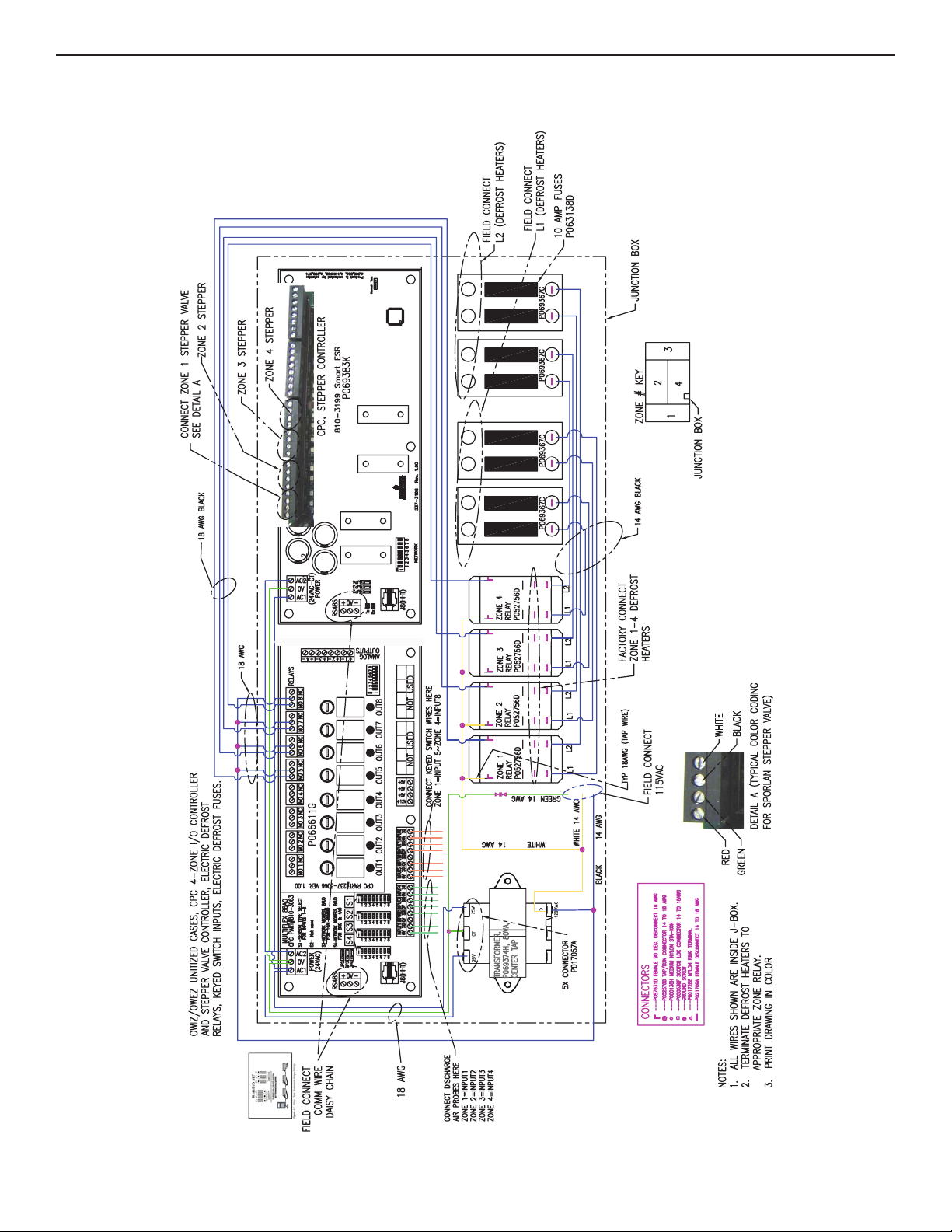
E.7 ELECTRICAL WIRING
CPC CONTROLLER W/ STEPPER CONTROL (DX)

DANFOSS (CO2)
ELECTRICAL WIRING E.7

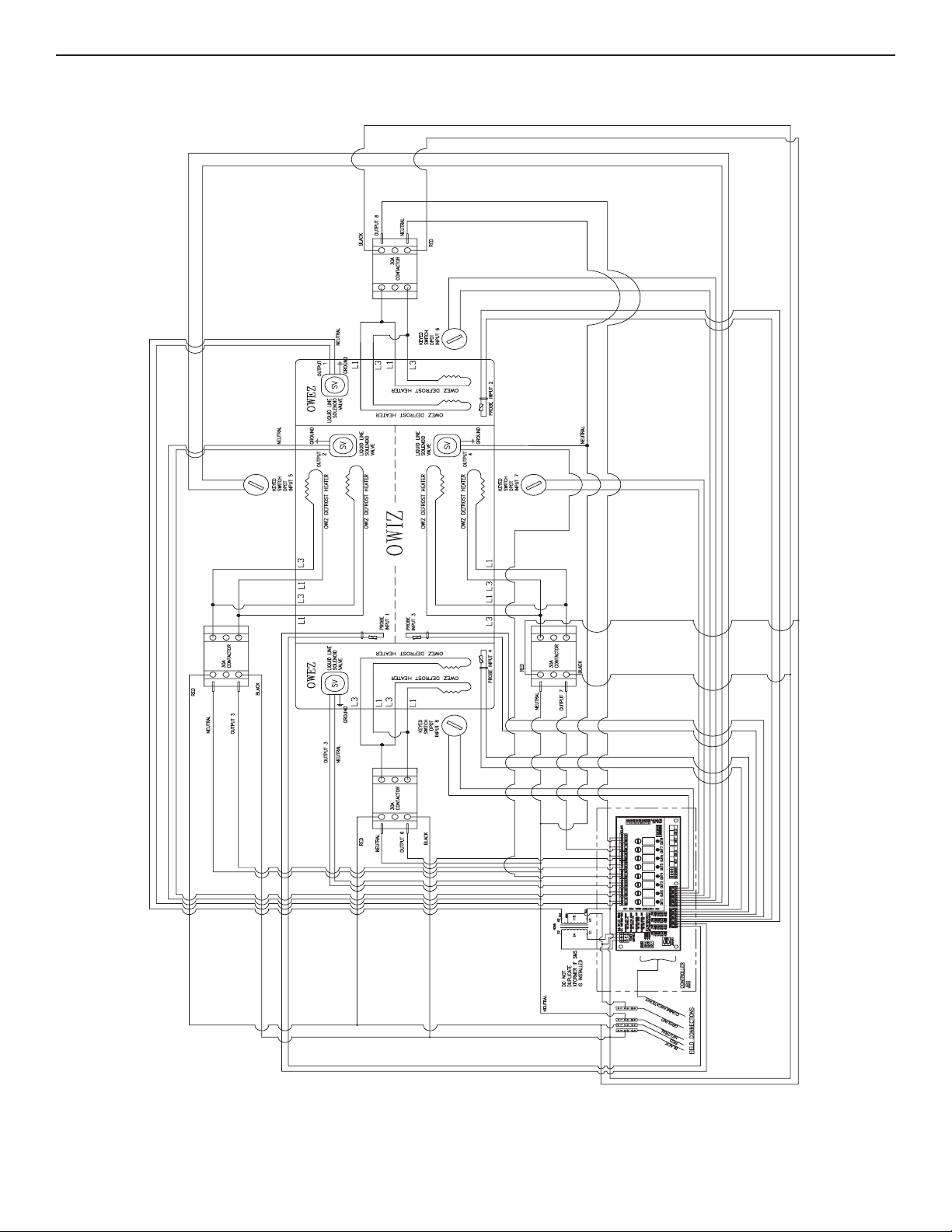
E.9 ELECTRICAL WIRING
DANFOSS (DX)

DANFOSS (5-8 ZONE)
ELECTRICAL WIRING E.10

F.1 SPORLAN PRESSURE-TEMPERATURE CHART
Square Inch Gauge
Pressure-Pounds Per
(°F) (°C) 134a (J ) 404A (S) 507 (P) 717 (A) 744 - CO2
TEMPERATURE REFRIGERANT (SPORLAN CODE)
43 6.1 38.0 90.6 94.6 63.1 577.6
42 5.6 37.0 88.8 92.8 61.6 569.3
44 6.7 39.0 92.4 96.5 64.7 586.0
46 7.8 41.1 96.0 100.2 67.9 603.1
45 7.2 40.1 94.2 98.3 66.3 594.5
48 8.9 43.2 99.8 104.1 71.1 620.5
47 8.3 42.2 97.9 102.1 69.5 611.7
50 10.0 45.4 103.6 108.0 74.5 638.3
49 9.4 44.3 101.7 106.0 72.8 629.3
60 15.6 57.4 126.0 129.2 92.9 733.1
65 18.3 64.0 137.3 140.7 103.2 784.2
70 21.1 71.1 149.3 153.0 114.2 838.1
55 12.8 51.2 115.3 118.3 83.4 684.4
75 23.9 78.7 162.0 165.9 125.9 894.9
80 26.7 86.7 175.4 179.6 138.4 954.9
85 29.4 95.2 189.5 194.1 151.8 1018
90 32.2 104.3 204.5 209.3 166.1 **
95 35.0 113.9 220.2 225.4 181.2 **
100 37.8 124.2 236.8 242.3 197.3 **
105 40.6 135.0 254.2 260.1 214.4 **
110 43.3 146.4 272.5 278.8 232.5 **
115 46.1 158.4 291.8 298.5 251.6 **
120 48.9 171.2 312.1 319.2 271.9 **
125 51.7 184.6 333.3 340.9 293.3 **
130 54.4 198.7 355.6 363.8 315.8 **
135 57.2 213.6 379.1 387.8 339.6 **
140 60.0 229.2 403.7 413.0 364.7 **
145 62.8 245.7 429.6 439.5 391.0 **
150 65.6 262.9 456.8 467.4 418.7 **
155 68.3 281.0 485.5 497.0 447.8 **
TEMPERATURE PRESSURE CHART - at sea level
Vacuum-Inches of Mercury
Bold Italic Figures
FORM IC-11-09 COPYRIGHT 2009 BY SPORLAN VALVE COMPANY, WASHINGTON, MO 63090 Printed in U.S.A.
(°F) (°C) 134a (J ) 404A (S) 507 (P) 717 (A) 744 - CO2
TEMPERATURE REFRIGERANT (SPORLAN CODE)
13 -10.6 13.8 46.6 49.3 26.5 363.4
12 -11.1 13.1 45.4 48.1 25.6 357.4
79.9
91.1
15 -9.4 15.0 49.0 51.8 28.4 375.6
14 -10.0 14.4 47.8 50.5 27.5 369.5
103.4
14.3
17 -8.3 16.4 51.5 54.3 30.4 388.0
16 -8.9 15.7 50.2 53.0 29.4 381.8
131.0
8.8
19 -7.2 17.7 54.0 56.9 32.4 400.7
18 -7.8 17.0 52.7 55.6 31.4 394.3
163.1
1.6
21 -6.1 19.1 56.6 59.6 34.6 413.8
20 -6.7 18.4 55.3 58.3 33.5 407.2
23 -5.0 20.6 59.3 62.4 36.8 427.1
22 -5.6 19.9 58.0 61.0 35.7 420.4
25 -3.9 22.1 62.1 65.3 39.0 440.7
24 -4.4 21.3 60.7 63.8 37.9 433.8
27 -2.8 23.7 64.9 68.2 41.4 454.6
26 -3.3 22.9 63.5 66.7 40.2 447.6
29 -1.7 25.3 67.8 71.2 43.8 468.8
28 -2.2 24.5 66.4 69.7 42.6 461.7
31 -0.6 26.9 70.8 74.3 46.3 483.4
30 -1.1 26.1 69.3 72.7 45.0 476.1
33 0.6 28.6 73.9 77.5 48.9 498.3
32 0.0 27.8 72.4 75.9 47.6 490.8
35 1.7 30.4 77.1 80.7 51.6 513.4
34 1.1 29.5 75.5 79.1 50.2 505.8
37 2.8 32.2 80.3 84.1 54.3 529.0
36 2.2 31.3 78.7 82.4 52.9 521.2
39 3.9 34.1 83.7 87.5 57.2 544.8
38 3.3 33.1 82.0 85.8 55.7 536.9
41 5.0 36.0 87.1 91.0 60.1 561.0
40 4.4 35.0 85.4 89.2 58.6 552.9
0.9
4.3 5.4
9.6 11.0
12.7 14.1 1.3 181.0
16.0 17.6 3.6 200.2
9.8
6.9
-35 -37.2 12.5 6.8 8.1 5.4 146.5
-30 -34.4
-25 -31.7
3.7
-20 -28.9
-18 -27.8 2.3 17.4 19.1 4.6 208.3
To determine subcooling for R-404A use BUBBLE POINT values (Temperatures above 50°F — Gray Background); to determine superheat for R-404A, use DEW POINT values (Temperatures 50°F and below).
** = exceeds critical temperature
-16 -26.7 0.8 18.9 20.6 5.6 216.5
-14 -25.6 0.4 20.4 22.2 6.7 225.0
-12 -24.4 1.1 22.0 23.8 7.8 233.8
-10 -23.3 1.9 23.6 25.5 9.0 242.7
-8 -22.2 2.8 25.3 27.3 10.3 251.9
-6 -21.1 3.6 27.0 29.1 11.5 261.3
-4 -20.0 4.6 28.8 30.9 12.9 271.0
-2 -18.9 5.5 30.7 32.8 14.3 280.9
0 -17.8 6.5 32.6 34.8 15.7 291.0
1 -17.2 7.0 33.6 35.8 16.4 296.2
2 -16.7 7.5 34.6 36.9 17.2 301.5
3 -16.1 8.0 35.6 37.9 18.0 306.8
4 -15.6 8.5 36.6 39.0 18.8 312.1
5 -15.0 9.1 37.7 40.1 19.6 317.6
6 -14.4 9.6 38.7 41.1 20.4 323.1
7 -13.9 10.2 39.8 42.3 21.2 328.6
11 -11.7 12.5 44.3 46.9 24.7 351.5
8 -13.3 10.8 40.9 43.4 22.1 334.2
9 -12.8 11.3 42.0 44.5 22.9 339.9
10 -12.2 11.9 43.1 45.7 23.8 345.7
21.8 7.3 5.8 18.6
20.3 3.9 2.2 16.6
18.7 0.1
14.8
(°F) (°C) 134a (J ) 404A (S) 507 (P) 717 (A) 744 - CO2
TEMPERATURE REFRIGERANT (SPORLAN CODE)
-60 -51.1
-55 -48.3
-50 -45.6
-45 -42.8 16.9 2.0 3.0 11.7 116.6
-40 -40.0

CONSTRAINT BRACKET INSTALLATION
The case constraint brackets can be installed
BASE FRAME CONSTRAINT BRACKET - 2 PER CASE
(BRACKET SHOWN HERE IS FOR A 5" TALL BASE FRAME,
CONSTRAINT BRACKETS ARE ALSO AVAILABLE
FOR ALL BASE FRAME HEIGHTS
USE (3) #10 SELF DRILLING / SELF TAPPING SCREWS
FOR ATTACHMENT TO THE BASE FRAME
ALTERNATE LOCATION
(BACK OF CASE)
USE (1) 0.5" OR (2) 0.375"
ANCHOR(S) FOR ATTACHMENT
TO THE STORE FLOOR
in 2 ways. Option 1 can be used on multi-deck cases
and uses an “L” bracket to attach the case to a vertical
wall, as shown below. Option 2 can be used on multideck cases or on cases that do not have a canopy.
Attach the “L” brackets to the base frames in either of
the locations shown below. Brackets are available for
all base frame heights.
ATTACK BRACKET TO WALL
USE (1) 0.5"
OR (2) 0.375" ANCHORS
CONSTRAINT BRACKET
ATTACH TO TOP OF CASE
USE (3) #10 SELF TAPPING
SCREWS
SEISMIC BRACKETS G.1
OPTION 1
OPTION 2
11/05
BRACKET CAN BE POSITIONED
ON EITHER SIDE OF THE
BASE FRAME

G.2 SEISMIC BRACKETS
5” BRACKETS

7” BRACKETS
SEISMIC BRACKETS G.3

G.4 SEISMIC BRACKETS
11” BRACKETS

15” BRACKETS
SEISMIC BRACKETS G.5

H.1 PARTS LIST
PARTS ORDERING
82
12
30
31
59
87
11
36
16
15
83
9
81
37
7
14
6
5
73
72
18
23
69
E01
E11
E10
2
17
74
26
4
3
1
24
77
E20
E09
MODEL
OWIZ

MODEL OWIZ
PARTS LIST H.2
Location Part Descriptions
Number
1 Kickplate, Storm Grey
2 Master Bumper, Featherstone, Smoke, White, French Vanilla, Black
3 Lower Front Panel, Painted
4 Color Band, Painted
5 Thermopane, Front Sill Glass
6 Flue Glass
7 Flue Glass Bracket
9 Deck Pan, Painted, Unpainted
11 Front Baffle, Painted
12 Honeycomb
14 Glass Cap, for Solid Panel and Glass Front Extensions
15 Rear Baffle
16 Sill Cap, Center
17 Nose Bumper, Polymer Custom Color
18 Pedestal, Painted
23 Electrical Junction Box
24 “J” Rail, for Kickplate
26 Front Panel, Painted
30 Corner Bumper, Featherstone, Smoke, White, French Vanilla, Black
31 Corner Casting, for Solid Panel and Glass Front Extensions
36 Plug Button
37 Corner Glass Support
59 Upper Front Extension Panel, Painted
69 Coil
72 Color Band Corner
73 Front Panel Corner
74 Glass Joint Trim
77 P-Trap
81 Wire Rack
82 Tag Moulding
83 Thermometer, and Bracket
87 End Assembly, Wraparound (Shown), Solid Flat End
E01 Defrost Heater
E02 Anti-Condensate Heater (Not Shown)
E03 Thermostats, Temperature and Defrost Termination Control, (Not Shown)
E09 Fan Motor - STATE HIGH EFFICIENCY OR STANDARD
E10 Fan Blade
E11 Fan Basket, 6”
E20 Fan Cord-Set - High Efficiency or Standard (Not Shown)

NOTES

NOTES

NOTES

WARRANTY
HEREINAFTER REFERRED TO AS MANUFACTURER
FOURTEEN MONTH WARRANTY. MANUFACTURER’S PRODUCT IS WARRANTED TO BE FREE FROM DEFECTS
IN MATERIAL AND WORKMANSHIP UNDER NORMAL USE AND MAINTENANCE FOR A PERIOD OF FOURTEEN
MONTHS FROM THE DATE OF ORIGINAL SHIPMENT. A NEW OR REBUILT PART TO REPLACE ANY DEFECTIVE
PART WILL BE PROVIDED WITHOUT CHARGE, PROVIDED THE DEFECTIVE PART IS RETURNED TO
MANUFACTURER. THE REPLACEMENT PART ASSUMES THE UNUSED PORTION OF THE WARRANTY.
This warranty does not include labor or other costs incurred for repairing, removing, installing, shipping, servicing, or handling of either defective parts or replacement parts.
The fourteen month warranty shall not apply:
1. To any unit or any part thereof which has been subject to accident, alteration, negligence, misuse or abuse, operation
on improper voltage, or which has not been operated in accordance with the manufacturer’s recommendation, or if the
serial number of the unit has been altered, defaced, or removed.
2. When the unit, or any part thereof, is damaged by fire, flood, or other act of God.
3. Outside the continental United States.
4. To labor cost for replacement of parts, or for freight, shipping expenses, sales tax or upgrading.
5. When the operation is impaired due to improper installation.
6. When installation and startup forms are not properly complete or returned within two weeks after startup.
THIS PLAN DOES NOT COVER CONSEQUENTIAL DAMAGES. Manufacturer shall not be liable under any circumstances for
any consequential damages, including loss of profit, additional labor cost, loss of refrigerant or food products, or injury to
personnel or property caused by defective material or parts or for any delay in its performance hereunder due to causes
beyond its control. The foregoing shall constitute the sole and exclusive remedy of any purchases and the sole and exclusive liability of Manufacturer in connection with this product.
The Warranties are Expressly in Lieu of All Other Warranties, Express or Implied and All Other Obligations or Liabilities
on Our Part. The Obligation to Repair or Replace Parts or Components Judged to be Defective in Material or
Workmanship States Our Entire Liability Whether Based on Tort, Contract or Warranty. We Neither Assume Nor
Authorize Any Other Person to Assume for Us Any Other Liability in Connection with Our Product.
MAIL CLAIM TO:
Hillphoenix
Display Merchandisers
1925 Ruffin Mill Road
Colonial Heights, VA 23834
1-800-283-1109
Refrigeration Systems &
Electrical Distribution Products
Hillphoenix
709 Sigman Road
Conyers, GA 30013
770-285-3200
06/00

Warning
Servicing & Case Care
When servicing or cleaning cases, observe the following
procedures to avoid case damage or injury:
Be certain that all electricity to the case is turned off before
servicing or cleaning to avoid electrical shock. In some
cases, more than one switch may need to be turned off to
completely de-energize the case.
Do not spray cleaning solution or water directly on fan
motors or any electrical connections.
All lighting components must be dried thoroughly before
installation and before re-energizing the lighting circuit.
Please refer to the Case Cleaning section of this installation manual.
Hillphoenix
1925 Ruffin Mill Rd.
Colonial Heights, VA 23834
Mon.-Fri. (8 a.m. to 5 p.m. EST)
Tel: 1-800-283-1109
Fax: 804-526-7450
Web site: www.hillphoenix.com
Due to our commitment to continuous improvement, all specifications are subject to change without notice.
Hillphoenix is a Sustaining Member of the American Society of Quality.
 Loading...