


INSTALLATION & OPERATIONS HANDBOOK
Self-Contained Floral Merchandiser
FEA
Table of Contents
Energy Data & Case Dimensions .................2-3
General Information .........................................4
Installation .........................................................5
Refrigeration Piping .........................................6
Refrigeration Components ..............................7
Electrical Connections ..................................... 8
Draining & Condensation ................................9
To ensure proper functionality and optimum performance, it is STRONGL Y recommended that Hill PHOENIX display
cases be installed/serviced by qualifi ed technicians who have experience working with commercial refrigerated
display merchandisers and storage cabinets. For a list of Hill PHOENIX-authorized installation/service contractors,
please visit our Web site at www.hillphoenix.com.
COMPONENT
LED Lighting ..............................................10-11
Airfl ow, Defrost & Temperature Control .......12
Use & Maintenance.........................................13
Parts Ordering ................................................14
Appendix A: Dixell Controller/Setpoints
Appendix B: Condensate Pump Diagrams
Appendix C: Wiring Diagrams
P079524G
08/10

ii

Important
At Hill PHOENIX
ployees, as well as the ongoing performance of our products, are top priorities. To that end, we include important
warning messages in all Hill PHOENIX installation and operation handbooks, accompanied by an alert symbol paired
with the word "DANGER", "WARNING", or "CAUTION".
®
, the safety of our customers and em-
▲
"DANGER" indicates an immediate threat of death
or serious injury if all instructions are not followed
carefully.
▲
"WARNING" indicates a possible threat of death
or serious injury if all instructions are not followed
carefully.
DANGER
WARNING
All warning messages will inform you of what the potential hazard is; how to reduce the risk of death, injury, or
damage; and what may happen if the instructions are not
properly followed.
CAUTION
▲
"CAUTION" indicates that failure to properly follow
instructions may result in case damage.
iii

LIABILTY NOTICE
For Cases with Shelf Lighting Systems
Hill PHOENIX does NOT design any of its shelf lighting systems or any of its display cases with shelf lighting systems for direct or indirect exposure to water or
other liquids. The use of a misting system or water hose on a display case with
a shelf lighting system, resulting in the direct or indirect exposure of the lighting
system to water, can lead to a number of serious issues (including, without limitation, electrical failures, fi re, electric shock, and mold) in turn resulting in personal
injury, death, sickness, and/or serious property damage (including, without limitation, to the display itself, to the location where the display is situated [e.g., store]
and to any surrounding property). DO NOT use misting systems, water hoses
or other devices that spray liquids in Hill PHOENIX display cases with lighted
shelves.
If a misting system or water hose is installed or used on a display case with a
shelf lighting system, then Hill PHOENIX shall not be subject to any obligations or
liabilities (whether arising out of breach of contract, warranty, tort [including negligence], strict liability or other theories of law) directly or indirectly resulting from,
arising out of or related to such installation or use, including, without limitation,
any personal injury, death or property damage resulting from an electrical failure,
fi re, electric shock, or mold.
P079211M, REVO
iv

R-744 (CO2) NOTICE
For Systems Utilizing R-744 (CO2) Refrigerant
For refrigeration units that utilize R-744 (CO2), pressure relief and pressure-regulating relief valves may need to be installed based on the system capacity. The
valves need to be located such that no stop valve is positioned between the relief
valves and the parts or section of the system being protected.
When de-energizing refrigeration units containing R-744 (CO
R-744 (CO
These valves are located on the refrigeration system and not on the case model.
If venting does occur, the valve must not be defeated, capped, or altered by any
means.
WARNING: Under no circumstances should any component be replaced or
added without consulting Hill PHOENIX Field Service Engineering. Utilizing
improper components may result in serious injury to persons or damage to
the system.
) refrigerant may occur through the pressure regulating relief valves.
2
), venting of the
2
v

E
NERGY
D
ATA
FEA
System Requirements
Minimum Circuit
Ampacity
Model Volts Phase Hz Wire
FEA 208 1 60 4-wire 33.2 45.7 65
Maximum
Overcurrent
ProtectionNo Drain Pan Drain Pan
Electrical Data
High Ef ciency
Fans
Model
FEA 7 1.05 77 1.3 94 0.8 47 1.38 160
per
Case
Fans
120 Volts 120 Volts 120 Volts 120 Volts
Amps Watts Amps Watts Amps Watts Amps Watts
Condenser
Fan
Drain
Pump
Maximum
Lights
Guidelines & Control Settings
24 hr Energy
Model
FEA 84 68 6-8 38 250
Usage
(kWh)
Suction Pressure
@ Case Outlet
(psig)
Superheat Set
Point @ Bulb
(°F)
Discharge
Air
(°F)
Discharge Air
Velocity
(FPM)
Condensing Unit Data
Model Volts Phase
FEA 208 1 60 3 21 107 R507 11.4
Frequency
(Hz) HP
RLA
(amps)
2
3
LRA
(amps) Refrig.
Lbs. of
Refrig.
1
Defrost Controls
Electric Defrost Timed-Off Defrost Hot Gas Defrost Reverse Air Defrost
Model
FEA 6 ---
1 Average discharge air velocity at peak of defrost.
2 RLA - Runing Load Amps
3 LRA - Locked Rotor Amps
4 “- - -” indicates not an option on this case model.
Defrosts
per Day
Fail-Safe
(min)
4
Termination
Temp (F)
Fail-Safe
(min)
--- 45 60 --- --- --- ---
Termination
Temp (F)
Fail-Safe
(min)
Termination
Temp (F)
Fail-Safe
(min)
Termination
Temp (F)
All measurements are taken per ARI 1200 - 2002 specifications.
COMPONENT
2

C
ASE
D
IMENSIONS
MODEL
FEA
99 in
[251.5 cm]
CONDENSING UNIT
54-1/4 in
[137.8 cm]
75-5/8 in
[198.1 cm]
18-7/8 in
[35.2 cm]
42-1/8 in
[xxx cm]
24-1/8 in
[xxx cm]
4-3/4 in
[12.1 cm]
28-5/8 in
[xxx cm]
46-1/8 in
[xxx cm]
29 in
[73.7 cm]
43-7/8 in
[xxx cm]
50-3/8in
[128.0 cm]
COIL
DRAIN
PLENUM
4-5/8 in
[11.7 cm]
24-1/8 in
[xxx cm]
54-1/4 in
[xxx cm]
COMPONENT
92-1/8 in
[xxx cm]
3

G
ENERAL INFORMATION
Thank you for choosing Hill PHOENIX for your food merchandising needs. This handbook contains important technical
information that will assist you with the installation of your new Hill PHOENIX display cases. By closely following the
instructions, you can expect peak performance; attractive fit and finish; and long case life.
We are always interested in your suggestions for improvements (e.g. case design, technical documents, etc.). Please feel
free to contact our Marketing Services group at the toll-free number listed below. Thank you for choosing Hill PHOENIX,
and we wish you the very best in outstanding food merchandising.
CASE DESCRIPTION
This manual specifically covers the O5M-NRG, O5DR-NRG O5DM-NRG, O5MH-NRG, O5DMH-NRG and ON5DMH-NRG
multi-deck merchandisers.
STORE CONDITIONS
Hill PHOENIX cases are designed to operate in an air-conditioned store that maintains a 75°F (24°C) store temperature and
55% (max) relative humidity (CRMA conditions). Case operation will be adversely affected by exposure to excessively high
ambient temperatures and/or humidity.
REFRIGERATION SYSTEM OPERATION
Air-cooled condensing units require adequate ventilation for efficient performance. Machine-room temperatures must be maintained at a minimum of 65°F in winter and a maximum of 95°F in summer. Minimum condensing temperatures should be no
less than 70°F.
CONTACTING THE FACTORY
If you need to contact Hill PHOENIX to obtain parts or warranty information, please call toll free 1-800-283-1109 and ask
for a Service Parts Representative. For technical questions regarding Hill PHOENIX display cases, please call toll free
1-800-283-1109 and and ask for Technical Support. For questions regarding our refrigeration systems or electrical distribution centers, please call our Systems Division Customer Service Department at 1-770-285-3100.
SHIPPING DAMAGE
Claims for obvious shipping damage must be 1) noted on either the freight bill or the express receipt and 2) signed by
the carrier's agent; otherwise, the carrier may refuse the claim. If damage becomes apparent after the equipment is
unpacked, retain all packing materials and submit a written request to the carrier for inspection within 14 days of receipt
of the equipment.
HILL PHOENIX
Case Division
1925 Ruffin Mill Rd.
Colonial Heights, VA 23834
Mon.-Fri. (8 a.m to 5 p.m EST)
Tel: 1-800-283-1109/Fax: 804-526-7450
Web site: www.hillphoenix.com
4

I
NSTALLATION
MOVING CASES
Hill PHOENIX FEA fl oral display cases are equipped with
lower structural tubes (see Fig. 1) that run the length of the
case. These tubes are designed to allow the case to be
moved into position by a forklift operator.
FLOOR PREP
1. Ask the general contractor if there have been changes
in the building dimensions since the print you are using
was issued. Also, ask for the points of reference from
which you should take dimensions to locate the cases.
2. Using chalk lines or a laser transit, mark the fl oor where
the cases are to be located for the entire lineup. The
lines should coincide with the outside edges of the lower
structural tubes.
3. Leveling is necessary to ensure proper case function
and to avoid potential damage. Locate the highest point
on the positioning line as a reference for determining the
proper height of the shim-pack levelers. A laser transit
is recommended for precision and requires just one person.
4. Locate the position of the lower structural tubes and spot
properly leveled shim packs at the appropriate locations.
LOWER
STRUCTURAL
TUBES
Fig. 1 Attaching the front and end kick plates.
LINE-UP & INSTALLATION
1. Move the case into position, being certain to leave at
least 6" of ventilation space at the top and back of the
case.
2. Using a “J” bar , raise the end of the case (under cross
support) and place the lower structural tubes on the
shim packs. Repeat on the other end of the case.
3. Once the lower structural tubes are properly placed on
the shim packs, check the vertical level by placing a
bubble level plumb to the rear edge of the case; then
add/remove shim levels as needed. To check the horizontal level, repeat this process after placing the bubble
level on the rear sill.
WARNING
▲
Be certain that your hands and feet are out of the way
before lowering the case after the removal of the casters. Failure to do so may result in serious injury.
5

R
EFRIGERATION
P
IPING
The expansion valve and other controls are located on the
left-hand side of the case and are accessible without lifting
the fan plenum.
The controls cluster may be reached by lifting the left-hand
deck pan. The compressor and condensing unit are located
on top of the case for easy access.
The diagram below illustrates all of the refrigeration components in the FEA case. The components surrounded by the
MODEL
FEA
Evaporator
Coil
box are located in the case tank. Basic definitions of these
components are listed on the preceding page.
If it becomes necessary to penetrate the case bottom for
any reason, make certain it is sealed afterward with cannedfoam sealant and white RTV.
CAUTION
▲
If brazing is necessary, place wet rags around the
area to avoid burning the polyurethane coating.
NOTE: FEA case contains
3 evaporator coils that are
piped in parallel.
Tank
Area
Flow Direction
Accumulator
Service
Valve
TXV
Bulb
1/4”
Access
Valve
Dual Pressure
Control
Compressor
TXV
High Pressure
Control
Condenser
Evaporator
Fans
Flow Direction
Filter
Drier
Sight
Glass
Service
Valve
Condenser
Fans
Receiver
6

R
EFRIGERATION
C
OMPONENTS
Access Valve - Access port on the evaporator that allows
service personnel to check system
pressure.
Accumulator - A device installed on the suction line that is
used to boil off small amounts of liquid refrigerant so liquid
does not reach the compressor.
Compressor - An electrically driven piston pump that
pumps vapor refrigerant from a low pressure level to a
higher pressure level.
Condenser - The component in a refrigeration system that
transfers the heat that was absorbed by the refrigerant in the
evaporator and the heat of compression from the system by
condensing the refrigerant.
Condenser Fans - Fan that forces air through the air cooled
condenser to aid heat transfer.
Low-Pressure Control - A device that protects the com-
pressor from low charge and high pressure.
Evaporator Coil- The component of the refrigeration sys-
tem that absorbs heat from the air by boiling liquid refrigerant to vapor.
Evaporator Fans - Fans that circulate air through the case
and force air through the evaporator to aid heat transfer.
Filter Drier - A device installed on the liquid line of a refrig-
eration system that removes water and other impurities from
the refrigerant in the lines during initial start-up.
High-Pressure Control - Non-adjustable pressure trans-
ducers that regulate condenser fan operation and protects
the compressor from high pressure.
Receiver - The component in a refrigeration system that
stores liquid refrigerant that is not being used by the system
in low load conditions or when the system is shut down.
Service Valve - A manually operated valve in the refrigera-
tion system that is used for various service operations such
as isolating the high or low sides of the system.
Sight Glass - A device installed on the liquid line of a refrig-
eration system that is used to determine if there is water or
vapor in the lines by visual inspection.
Thermostatic Expansion Valve (TXV) - A valve that con-
trols the fl ow of liquid refrigerant to the evaporator coil and
also separates the high pressure side of the system from
low pressure side of the system.
Thermostatic Expansion Valve (TXV) Bulb - A bulb that is
attached to the suction line of the evaporator that controls
the TXV. Inside the bulb is a charge that reacts to temperature and regulates the fl ow of refrigerant through the expan-
sion valve.
7

E
LECTRICAL
Electrical hookups for the FEA are made to a centrally-located electrical box. The light ballasts are also mounted in
the electrical junction box. Access to the box can be gained
by removing the rear access panel. See the appendix sec-
tion at the end of this manual for more detailed electrical
wiring information.
C
ONNECTIONS
MODEL
FEA
8

D
RAINING
& C
ONDENSATION
The condensate pumps have been designed to remove
excess moisture that is created during the operation of the
case. The drain outlet is located beneath the deck pans in
the front-center section of the case.
Pump 1 pushes the condensate up through the rear area of
the case into the condensate reservoir in Pump 2. Pump
2 then carries the condensate out of the top of the case
through a 30-foot long, clear vinyl 3/8" ID hose with quick
connect, emptying into the store's drainage system.
Pump 2 is provided with an emergency fail-safe switch designed to turn off Pump 1 as Pump 2 reaches its maximum
MODEL
FEA
capacity. Pump 2 will continue to pump until the switch is
turned off. Each pump must remain plugged into its design
receptacle for the emergency fail-safe switch to operate
properly.
An optional heated condensate pan may be substituted for
pump 2. The same receptacle is used; however, the emergency fail-safe switch and wiring are removed.
Care should be given to assure that all connections are
water tight and properly sealed.
PUMP 2
FLOW
CONDENSATE
RESERVOIR
(HEATED PAN
IF REQUESTED)
CONDENSING UNIT
PUMP 1
FLOW
COIL
PLENUM
9

LED L
IGHTING
GENERAL INFORMATION
The Hill PHOENIX LED power supplies are located inside
the grounded, sheet-metal structure of the display case in
the same location that the T8 ballast would normally occupy – typically a slide out ballast tray under the case or in
the cornice area.
The LED lighting system has an ON/OFF switch that is located in the upper left-hand corner of the lighting assembly.
Once cases have been properly positioned in the store and
the electrician has connected the lighting circuit, Hill
PHOENIX luminaires may be turned on to verify that all
lights are connected and working properly.
To ensure peak performance, it is advisable to run the LED
lights only when the store climate control is on and case
refrigeration is started. NOTE: it is highly recommended
that the ambient store temperature not exceed 80F.
Once store power is connected and the light circuit is energized, the LED system should operate without the need
for any signifi cant maintenance for several years. Should
a power supply need to be removed and/or replaced, turn
off the power to the case before proceeding. Be certain to
replace the power supply with genuine Hill PHOENIX parts
or a comparable UL-listed Class-2 rated regulated 24V DC
power supply with 100W output capacity.
REMOVING SHELF LUMINAIRES
1. Unplug the luminaire.
Re-installing shelf luminaires:
1. Place hook into shelf roll form at shelf front and rotate
rear of luminaire toward the shelf.
2. Depress the rear clip so that luminaire can fi nish rotation
and until clip engages the shelf bracket.
REMOVING NON-SHELF LUMINAIRES
2. Pinching the latching clips
inward at the ends of the
luminaire, rotate luminaire
up at each end until hooks
are free, then remove.
DANGER
▲
SHOCK HAZARD
Always disconnect power to case when cleaning, servicing or confi guring components of the
LED lighting system. Failure to do so may result in serious injury or death.
WARNING
▲
Using improper DC power supplies may damage the luminaires, resulting in sub-standard
operation and increased chances of safety
issues/injury.
WARNING
▲
Never replace a 24V DC power supply with a
T8 or T5 ballast of any kind! Ballasts use
alternating current (AC) instead of direct current (DC) and operate at a much higher voltage than is used by this LED system. Doing
so will damage the LED system and increases
the chance of safety issues/injury.
1. Simultaneously squeeze
the plastic clips at each end.
Re-installing a non-shelf luminaire:
1. Align the 4-pole jack with the 4-pole connector on the
clip-in LED luminaire.
2. Push into place – side clips will engage on the sheet
metal of the case.
3. Fasten anti-tamper bracket into sheet metal of case
with #8 screw at end opposite the 4-pole in-line connector.
2. When the hooks are disen gaged, pull the luminaire
free.
10

A
IRFLOW
, D
EFROST
& T
EMP
C
ONTROLS
AIR FLOW
FEA cases have been designed to provide maximum product capacity within the refrigerated air envelope. It is important that you DO NOT overload the food product display to
avoid impinging on the air fl ow pattern.
Overloading will cause malfunction and the loss of proper
temperature levels, particularly when discharge and return
air sections are covered. Please keep products within the
load-limit lines shown on in the diagram below.
DEFROST & TEMP CONTROLS
The defrost and temperature controls of FEA cases are
initiated by a Dixell XR03CX rack controller.
MODEL
FEA
The single time-off defrost is initiated by the Dixell XR03CX
controller mounted in the electrical control box. During defrost, all valves close and the pump cycles OFF.
It is important to consult the guidelines and control setting
shown on page 4 before setting defrost times. Further adjustment may be required depending on store conditions.
Dixell controller information and setpoints are located in this
manual's Appendix section.
DISCHARGE................1
CONDENSING UNIT
1
2
3
LOAD LIMIT.................2
AIR FLOW....................3
RETURN AIR GRILL...4
4
COIL
PLENUM
11

U
UNIT
COIL
PLENUM
SE
& M
AINTENANCE
CASE CLEANING
Hill PHOENIX cases are designed to facilitate cleaning. All
surfaces pitch to a deep-drawn drain trough that angles toward the front of the case where the waste outlet is located
for easy access.
CLEANING PROCEDURES
• A periodic cleaning schedule should be established to
maintain proper sanitation, insure maximum operating
efficiency, and avoid the corrosive action of food fluids
on metal parts that are left on for long periods of time.
We recommend cleaning once a week.
• To avoid shock hazard, be sure all electrical power is
turned off before cleaning. In some installations, more
than one disconnect switch may have to be turned off to
completely de-energize the case.
• Check waste outlet to insure it is not clogged before
starting the cleaning process and avoid introducing water faster than the case drain can carry it away.
• Avoid spraying cleaning solutions directly on electrical
connections.
• Allow cases to be turned off long enough to clean any
frost or ice from coil and pans.
• Use mild detergent and warm water. When necessary,
water and baking soda solution will help remove case
odors. Avoid abrasive scouring powders or pads.
• Under no circumstances should abrasive cleaning solutions such as scouring powders or steel wool be used to
clean non-glare glass.
• Use warm water and a disinfecting cleaning solution
when cleaning underneath the cases.
• When removing deck pans for cleaning, gently set the
pans on the ground in a vertical position up against the
front of the case. If equipped with the optional quick
connects, disconnect the coolant lines from the pans for
cleaning. Use warm – not hot – water when cleaning
the deck pans.
POSITIVE DRAIN-OFF
DANGER
▲
SHOCK HAZARD
Always disconnect power to case when servicing
or cleaning. Failure to do so may result in serious
injury or death.
12
WARNING
▲
Exercise extreme caution when working in a case
with the coil cover removed. The coil contains
many sharp edges that can result in severe cuts to
the hands and arms.

P
ARTS
O
RDERING
Contact the Service Parts Department at:
1-800-283-1109
Provide the following information about the part you are
ordering:
• Model number and serial number of the case for
which the part is intended.
• Length of the part (if applicable).
• Color of part (if painted) or color of polymer part.
• Whether part is for left- or right-hand application.
• Quantity
*Serial plate is located on the back of the case on the left-hand side.
If the parts are to be returned for credit, ask the Parts
Department to furnish you with a Return Material
Authorization Number.
13

APPENDIX A:
DIXELL CONTROLLER/SETPOINTS

dIXEL
Operating Manual
DIGITAL CONTROLLE R
XR03CX – XR04CX
1. CONTENTS
1. Contents __________________________________________________________________________1
2. General warnings ___________________________________________________________________ 1
3. General description__________________________________________________________________1
4. Regulation_________________________________________________________________________ 1
5. Defrost ___________________________________________________________________________ 1
6. Front panel commands_______________________________________________________________ 1
7. Parameters ________________________________________________________________________ 1
8. Digital inputs_______________________________________________________________________ 2
9. Installation and mounting _____________________________________________________________ 2
10. Electrical connections________________________________________________________________2
11. How to use the hot key_______________________________________________________________ 2
12. Alarm signalling_____________________________________________________________________ 2
13. Technical data______________________________________________________________________ 2
14. Connections _______________________________________________________________________ 3
15. Default setting values ________________________________________________________________ 3
2. GENERAL W ARNINGS
PLEASE READ BEFORE USING THIS MANUAL
1. This manual is part of the product and should be kept near the instrument for easy and quick
reference.
2. The instrument shall not be used for purposes different from those described hereunder. It
cannot be used as a safety device.
3. Check the application limits before proceeding.
SAFETY PRECAUTIONS
• Check the supply voltage is correct before connecting the instrument.
• Do not expose to water or moisture: use the controller only within the operating limits avoiding
sudden temperature changes with high atmospheric humidity to prevent formation of
condensation
• Warning: disconnect all electrical connections before any kind of maintenance.
• Fit the probe where it is not accessible by the End User. The instrument must not be opened.
• In case of failure or faulty operation send the instrument back to the distributor or to “Dixell
S.p.A.” (see address) with a detailed description of the fault.
• Consider the maximum current which can be applied to each relay (see Technical Data).
• Ensure that the wires for probes, loads and the power supply are separated and far enough from
each other, without crossing or intertwining.
• In case of applications in industrial environments, the use of mains filters (our mod. FT1) in
parallel with inductive loads could be useful.
3. GENERAL DESCRIPTION
The XR03CX, in 32×74 x50mm short format, is microprocessor based controller suitable for applications on
normal temperature refrigerating units. It provides two relay output: one for compressor and th e other one for
alarm signalling or as auxiliary output. It provides an NTC probe input and a digital input for alarm signalling,
for switching the auxiliary output or for s tart defrost. The instrument is fully configurable through special
parameters that can be easily progr ammed through the keyboard or the by HOTKEY.
The XR04CX, in 32×74 x50mm short format, is microprocessor based controller suitable for applications on
normal or low temperature refrigerating units. It provides two relay output: one for compressor and the other
one for defrost. It provides two NTC probe inputs, one for room temperature and other one to control defrost
termination. The instrument is fully configurable through special parameters that can be easily programmed
through the keyboard or the by HOTKEY.
4. REGULA TION
The regulation is performed according to
the temperature measured by the
thermostat probe with a positive
differential from the set point: if the
temperature increases and reaches set
point plus differential the compressor is
started and then turned off when the
temperature reaches the set point value
again.
In case of fault in the thermostat probe the start and stop of the compressor are timed through
parameters “Cy” and “Cn”.
5. DEFROST
XR03CX
Defrost is performed through a simple stop of the compressor. Parameter “id” controls the interval
between defrost cycles, while its length is controlled by parameter “Md”.
XR04CX
Two defrost modes are available through the “td” parameter:
• td=EL → defrost through electrical heater (compressor OFF)
• td=in → hot gas defrost (compressor ON).
Other parameters are used to control the interval between defrost cycles (id) ), its maximum length
(Md) and two defrost modes: timed or controlled by the evaporator’s probe. At the end of defrost
dripping time is started, its length is set in the dt parameter. With dt=0 the dripping time is disabled.
1592020130
6. FRONT PANEL COMMANDS
To display target set point, in
programming mode it selects a
parameter or confirm an
operation
To start a manual defrost
In programming mode it
browses the parameter codes
or increases the displayed
KEYS COMBINATION
+
+
+
LED MODO SIGNIFICATO
To lock or unlock the keyboard
To enter in programming mode
To return to room temperature display
value
In programming mode it
browses the parameter codes
AUX
or decreases the displayed
value
On Compressore enabled
Flashing Anti short cycle delay enabled (AC parameter)
On Defrost in progress
Flashing Dripping in progress
On Measurement unit
Flashing Programming mode
On Measurement unit
Flashing Programming mode
HOW TO SEE THE SET POINT
1. Push and immediately release the SET key, the set point will be showed;
2. Push and immediately release the SET key or wait about 5s to return to normal visualisation.
HOW TO CHANGE THE SETPOINT
1. Push the SET key for more than 2 seconds to change the Set point value;
2. The value of the set point will be displayed and the “°C” or “°F” LED starts blinking;
3. To change the Set value push the o or n arrows within 10s.
4. To memorise the new set point value push the SET key again or wait 10s.
HOW TO START A MANUAL DEFROST
Push the DEF
HOW TO CHANGE A PARAMETER VALUE
To change the parameter’s value operate as follows:
1. Enter the Programming mode by pressing the SET+
blinking).
2. Select the required parameter. Press the “SET” key to display its value
3. Use
4. Press “SET” to store the new value and move to the following parameter.
To exit: Press SET+
NOTE: the set value is stored even when the procedure is exited by waiting the time-out to expire.
key for more than 2 seconds and a manual defrost will start
or to change its value.
or wait 15s without pressing a key.
keys for 3s (“°C” or “°F” LED starts
HIDDEN MENU
The hidden menu includes all the parameters of the instrument.
HOW TO ENTER THE HIDDEN MENU
1. Enter the Programming mode by pressing the SET+
blinking).
2. Released the keys, then push again the SET+
displayed immediately followed from the Hy parameter.
NOW YOU ARE IN THE HIDDEN MENU.
3. Select the required parameter.
4. Press the “SET” key to display its value
or to change its value.
5. Use
6. Press “SET” to store the new value and move to the following parameter.
To exit: Press SET+
NOTE1: if none parameter is present in L1, after 3s the “nP” message is displayed. Keep the keys
pushed till the L2 message is displayed.
NOTE2: the set value is stored even when the procedure is exited by waiting the time-out to expire.
HOW TO MOVE A PARAMETER FROM THE HIDDEN MENU TO THE FIRST
LEVEL AND VICEVERSA.
Each parameter present in the HIDDEN MENU can be removed or put into “THE FIRST LEVEL” (user
level) by pressing SET+
point is on.
TO LOCK THE KEYBOARD
• Keep pressed for more than 3s the and keys.
• The “OF” message will be displayed and the keyboard will be locked. If a key is pressed more
than 3s the “OF” message will be displayed.
TO UNLOCK THE KEYBOARD
Keep pressed together for more than 3s the and keys till the “on” message will be displayed.
or wait 15s without pressing a key.
. In HIDDEN MENU when a parameter is present in First Level the decimal
keys for 3s (“°C” or “°F” LED starts
keys for more than 7s. The L2 label will be
7. P ARAMETERS
REGULATION
1592020130 XR03_04CX GB 16. 01.07.doc XR03CX – XR04CX

dIXEL
Hy Differential: (0,1°C ÷ 25°C) Intervention differential for set point. Compressor Cut IN is SET
POINT + differential (Hy). Compressor Cut OUT is when the temperature reaches the set point.
LS Minimum SET POINT: (-55°C÷SET/-58°F÷SET): Sets the minimum value for the set point..
US Maximum SET POINT: (SET÷99°C/ SET÷99°F). Set the maximum value for set point.
ot First probe calibra t ion: (-9.9÷9.9°C) allows to adjust possible offset of the first probe.
P2 Evaporator probe presence: n= not present; y= the defrost stops by temperature. (Only
XR04CX)
oE Second probe calibration: (-9.9÷9.9°C) allows to adjust possible offset of the second probe.
(Only XR04CX)
od Outputs activation delay at start up: (0÷99min) This function is enabled at the initial start up of
the instrument and inhibits any output activation for the period of time set in the parameter.
AC Anti-short cycle delay: (0÷50 min) minimum interval between the compressor stop and the
following restart.
Cy Compressor ON time with faulty probe: (0÷99 min) time during which the compressor is active
in case of faulty thermostat probe. With Cy=0 compressor is always OFF.
Cn Compressor OFF time with faulty probe: (0÷99 min) time during which the compressor is OFF
in case of faulty thermostat probe. With Cn=0 compressor is always active.
CH Kind of Action (Only XR03CX): cL= cooling action; Ht = heating action;
DISPLAY
CF Measurement unit: (°C÷°F) °C =Celsius; °F =Fahrenheit. WARNING: When the measurement
unit is changed the SET point and the values of the parameters Hy, LS, US, oE, o1, AU, AL
have to be checked and modified if necessary).
rE Resolution (only for °C):(dE ÷ in) dE= decimal between -9.9 and 9.9°C; in= integer
Ld Default display: (P1 ÷ P2) P1= thermostat probe; P2= evaporator probe. SP=Set point (Only
XR04CX)
dy Display delay: (0÷15 min.) when the temperature increases, the display is updated of 1 °C/1°F
after this time.
DEFROST
td Defrost type: (EL – in) EL= electrical heater, compressor OFF; in= hot gas, compressor ON;
dE Defrost termination temperature (Only XR04CX): (-50÷50°C) if P2=Y it sets the temperature
measured by the evaporator probe, which causes the end of defrost.
id Interval between defrost cycles: (0÷99 ore) Determines the time interval between the
beginning of two defrost cycles.
Md Maximum length for defrost: (0÷99 min. with 0 no defrost) when P2=n, (not evaporator probe:
timed defrost) it sets the defrost duration, when P2 = y (defrost end based on temperature) it sets
the maximum length for defrost.
dd Start defrost delay: ( 0÷99min) This is useful when different defrost start times are necessary to
avoid overloading the plant.
dF Display during defrost: (rt / it / St / dF) rt= real temperature; it= start defrost temperature; SP=
SET-POINT; dF= label dF.
dt Drip time: (0÷99 min) time interval between reaching defrost termination temperature and the
restoring of the control’s normal operation. This time allows the evaporator to eliminate water
drops that might have formed due to defrost.
dP Defrost at power –on: (y÷n) y= at power on defrost starts; n= defrost doesn’t start at power-on
ALARMS
AU Maximum temperature alarm: (AL÷99°C) when this temperature is reached the alarm is
enabled, after the “Ad” delay time.
AL Minimum temperature alarm: (-55÷AU°C) when this temperature is reached the alarm is
enabled, after the “Ad” delay time.
Ad Temperature alarm delay: (0÷99 min) time interval between the detect ion of an alarm conditi on
and alarm signalling.
dA Exclusion of temperature alarm at startup: (0÷99 min) time interval between the detection of
the temperature alarm condition after instrument power on and alarm signalling.
tb Silencing buzzer (n-y):(Only XR03CX) n= silencing disabled, alarm relay stays on till alarm
conditions lasts; y= silencing enabled: alarm relay is switched OFF by pressing a key during an
alarm;
o1 Auxiliary relay configuration (dF/Fn/AL/AU/db): (Only XR03CX) dF= defrost; Fn= Fans; AL=
Alarm; AU= auxiliary; db= neutral zone;
AP Alarm relay polarity (cL-OP): (Only XR03CX) cL= when active is closed; OP= when active is
opened
DIGITAL INPUT (Only XR03CX)
iP Digital input polarity: (oP ÷ cL) oP= activated by closing the contact; cL= activated by openi ng
the contact;
iF Digital input configuration: (EA/bA/do/dF/Au/Hc) EA= external alarm: “EA” message is
displayed; bA= serious alarm “CA” message is displayed; do= door switch function; dF= defrost
activation; Au =not used; Hc= inversion of the kind of action;
di Digital input delay: (0÷99 min) with iF=EA or bA delay between the detection of the external
alarm condition and its signalling. . With iF=do it represents the delay to activate the door open
alarm.
dC Compressor and fan status when open door: (no/Fn/cP/Fc): no= normal; Fn = Fans OFF; cP
=Compressor OFF; Fc = Compressor and fans OFF;
rd Regulation with door open: (n÷y) n = no regulation if door is opened; Y= when di is elapsed
regulation restarts even if door open alarm is present;
OTHER
d1 Thermostat probe display (read only)
d2 Evaporator probe display (read only)
Pt Parameter code table
rL Software release
(Only XR03CX)
Operating Manual
8. DIGIT AL INPUTS
The free voltage digital input is programmable in different configurations by the “iF” parameter.
DOOR SWITCH (iF=do)
It signals the door status and the corresponding relay output status through the “dC” parameter: no =
normal (any change); Fn = Fan OFF; CP = Compressor OFF; FC = Compressor and fan OFF.
Since the door is opened, after the delay time set through parameter “di”, the door alarm is enabled,
the display shows the message “dA” and the regulation restarts if rd = y. The alarm stops as soon
1592020130
as the external digital input is disabled again. With the door open, the high and low temperature alarms
are disabled.
EXTERNAL ALARM (iF=EA)
As soon as the digital input is activated the unit will wait for “di” time delay before signalling the “EA”
alarm message. The outputs status don’t change. The alarm stops just after the digital input is deactivated.
SERIOUS ALARM (iF=bA)
When the digital input is activated, the unit will wait for “di” delay before signalling the “CA” alarm
message. The relay outputs are switched OFF. The alarm will stop as soon as the digital input is deactivated.
SWITCHING SECOND RELAY ON (iF=Au)
When o1=Au it switches on and off the second relay.
START DEFROST (iF=dF)
It starts a defrost if there are the right conditions. After the defrost is finished, the normal regulation will
restart only if the digital input is disabled otherwise the instrument will wait until the “dd” safety time is
expired.
INVERSION OF THE KIND OF ACTION: HEATING - COOLING (iF=Hc)
This function allows to invert the regulation of the controller: from cooling to heating and viceversa.
9. INST ALLA TION AND MOUNTING
Instrument XR03CX and XR04CX shall be mounted on vertical
panel, in a 29x71 mm hole, and fixed using the special bracket
supplied.
The temperature range allowed for correct operation is 0÷60 °C.
Avoid places subject to strong vibrations, corrosive gases,
excessive dirt or humidity. The same recommendations apply to
probes. Let air circulate by the cooling holes.
10. ELECTRICAL CONNECTIONS
The instrument is provided with screw terminal block to connect cables with a cross section up to 2,5
2
mm
. Before connecting cables make sure the power supply complies with the instrument’s
requirements. Separate the probe cables from the power supply cables, from the outputs and the
power connections. Do not exceed the maximum current allowed on each relay, in case of heavier
loads use a suitable external relay.
1.1 PROBES
The probes shall be mounted with the bulb upwards to prevent damages due to casual liquid
infiltration. It is recommended to place the thermostat probe away from air streams to correctly
measure the average room temperature. Place the defrost termination probe among the evaporator
fins in the coldest place, where most ice is formed, far from heaters or from the warmest place during
defrost, to prevent premature defrost termination.
11. HOW TO USE THE HOT KEY
1.2 HOW TO PROGRAM THE HOT KEY FROM THE INSTRUMENT (UPLOAD)
1. Program one controller with the front keypad.
2. When the controller is ON, insert the “Hot key” and push
followed a by flashing “Ed”
3. Push “SET” key and the “Ed” will stop flashing.
4. Turn OFF the instrument remove the “Hot Key”, then turn it ON again.
NOTE: the “Er” message is displayed for failed programming. In this case push again o key if you want
to restart the upload again or remove the “Hot key” to abort the operation.
key; the "uP" message appears
1.3 HOW TO PROGRAM AN INSTRUMENT USING HOT KEY (DOWNLOAD)
1. Turn OFF the instrument.
2. Insert a programmed “Hot Key” into the 5 PIN receptacle and then turn the Controller ON.
3. Automatically the parameter list of the “Hot Key” is downloaded into the Controller memory, the
“do” message is blinking followed a by flashing “Ed”.
4. After 10 seconds the instrument will restart working with the new parameters.
5. Remove the “Hot Key”..
NOTE: the “Er” message is displayed for failed programming. In this case push again o key if you want
to restart the upload again or remove the “Hot key” to abort the operation.
12. ALARM SIGNALLING
Mess. Cause Outputs
"P1" Room probe failure Compressor output according to “Cy” e “Cn”
"P2" Evaporator probe failure Defrost end is timed (Only XR04CX)
"HA" Maximum temperature alarm Outputs unchanged
"LA" Minimum temperature alarm Outputs unchanged
“EA” External alarm Outputs unchanged
“CA” Serious external alarm All outputs OFF.
“dA” Door Open Compressor and fans restarts
1.4 ALARM RECOVERY
Probe alarms P1” and “P2” start some seconds after the fault in the related probe; they automatically
stop some seconds after the probe restarts normal operation. Check connections before replacing the
probe. Temperature alarms “HA” and “LA” automatically stop as soon as the temperature returns to
normal values.
Alarms “EA” and “CA” (with iF=bA) recover as soon as the digital input is disabled.
13. TECHNICAL DATA
Housing: self extinguishing ABS.
Case: frontal 32x74 mm; depth 60mm;
Mounting: panel mounting in a 71x29mm panel cut-out
1592020130 XR03_04CX GB 16. 01.07.doc XR03CX – XR04CX

dIXEL
p
Protection: IP20; Frontal prote ction: IP65
Connections: Screw terminal block ≤ 2,5 mm
2
wiring.
Operating Manual
Power supply: according to the model: 12Vac/dc, ±10%; 24Vac/dc, ±10%; 230Vac ±10%, 50/60Hz,
110Vac ±10%, 50/60Hz
Power absorption: 3VA max
Display: 2 digits, red LED, 14,2 mm high; Inputs: Up to 2 NTC or PTC probes.
Digital input: free voltage contact
Relay outputs: compressor SPST 8(3) A, 250Vac; or 20(8)A 250Vac
defrost or Aux: SPDT 8(3) A, 250Vac
Data storing: on the non-volatile memory (EEPROM).
Kind of action: 1B; Pollution grade: 2;Software class: A.;
Rated impulsive voltage: 2500V; Overvoltage Category: II
Operating temperature: 0÷60 °C; Storage temperature: -30÷85 °C.
Relative humidity: 20÷85% (no condensing)
Measuring and regulation range: NTC probe: -40÷110°C (-40÷230°F);
Resolution: 0,1 °C or 1°C or 1 °F (selectable); Accuracy (ambient temp. 25°C): ±0,7 °C ±1 digit
14. CONNECTIONS
XR03CX –20A o 8A Compressor
NOTE: The compressor relay is 20(8)A or 16(6)A depending on the model.
NOTE: 120Vac or 24Vac/dc or 12Vac/dc connect to 6-7
XR04CX –20A o 8A Compressor
1592020130
dd Start defrost d elay 0 ÷ 99 min. 0
dF Display during defrost rt – in – SP – dF it
dt Drip time 0 ÷ 99 min 0
dP Defrost at power-on y - n n
ALARMS
AU Maximum temperature alarm ALL÷99°C / ALL÷210°F
AL Minimum temperature alarm -55°C÷ALU/-67°F÷ALU
Ad Temperature alarm delay 0 ÷ 99 min 15
Exclusion of temperature alarm at
dA
startup
DIGITAL INPUT (Only XR03CX)
iP Digital input polarity cL – oP cL
iF Digital input configuration
di Digital input delay 0 ÷ 99 min 5
Compressor and fan status when open
dC
door
rd Regulation with door open n - Y y
OTHER
d1 Thermostat probe display Read Only - - -
d2 Evaporator probe display Read Only - - -
Pt Parameter code table Read Only - - -
rL Firmware release Read Only - - -
0 ÷ 99 min 90
EA – bA – do – dF –
Au– db
no /Fn / cP / Fc FC
99 °C / 99
°F
-55 °C / -55
°F
EA
NOTE: The compressor relay is 20(8)A or 16(6)A depending on the model.
NOTA: 120Vac o 24Vac/dc o 12Vac/dc connect to 6 and 7
15. DEFAULT SETTING VALUES
LAB
EL
REGULATION
Hy Differential 0.1 ÷ 25°C/1 ÷ 45°F 2.0°C / 4 °F
LS Minimum Set Point -55°C÷SET/-67°F÷SET
US Maximum Set Point SET÷99°C/ SET÷210°F
ot First probe calibration -9.9÷9.9°C/-18÷18°F 0.0
Second probe presence (Only
P2
XR04CX)
Second probe calibration (Only
oE
XR04CX)
od Outputs activat i on delay at start up 0 ÷ 99 min 0
AC Anti-short cycle delay 0 ÷ 50 min 1
Cy Compressor ON time faulty probe 0 ÷ 99 min 15
Cn Compressor OFF time faulty probe 0 ÷ 99 min 30
CH Kind of Action (Only XR03CX) cL ÷ Ht cL
DISPLAY
CF Measurement units °C - °F °C / °F
rE Resolution (only for °C) dE – in dE
Ld Default Display (Only XR04CX) P1-P2 - SP P1
dy Display delay 0 ÷ 15 min 0
DEFROST
td Defrost type EL – in EL
dE Defrost termination temperature -50÷50°C/-58÷122°F
id Interval between defrost cycles 0 ÷ 99 hours 6
Md Maximum length for defrost 0 ÷ 99 min. 30
DESCRIPTION RANGE DEFAULT
-55 °C /55°F
99 °C /
99°F
n – Y y
-9.9÷9.9°C/-18÷18°F 0.0
8.0 °C / 46
°F
dIXEL S.p.a.
Z.I. Via dell’Industria, 27 - 32010 Pieve d’Alpago (BL) ITALY
tel. +39 - 0437 - 98 33 - fax +39 - 0437 - 98 93 13
htt
://www.dixell.com E-mail: dixell@dixell.com
1592020130 XR03_04CX GB 16. 01.07.doc XR03CX – XR04CX

LBL DESCRIPTION RANGE DEFAULT LEVEL SETTING
REGULATION
Setpoint 37
Hy Differential
1+45°F
2°F L1 4
LS Minimum Set Point -67°F+SET 25°F L2 25
US Maximum Set Point SET+99°F 40°F L2 50
ot First probe calibration -18+18°F 0°F L2 0
P2 Second probe presence n-Y y L2 Y
oE Second probe calibration 18+18°F 0°F L2 0
AC Anti-short cycle delay 0+50 min 2 L2 2
Cy Compressor ON time faulty probe 0+99 min 12 L2 12
Cn Compressor OFF time faulty probe 0+99 min 4 L2 4
DISPLAY
CF Measurement units °C-°F °F L2 °F
rE
Resolution (only for °C)
dE-In in L2 -
Ld Default Display P1-P2 P1 L2 P1
dy Display delay 0+15 min 0 L2 0
DEFROST
dE Defrost termination temperature
58+99°F
52°F L1 55
Id Interval between defrost cycles 0+99 hours 4 L1 4
ηd
Maximum length for defrost 0+99 min 28 L1 40
dF Display during defrost rt-It-dF-St rt L2 rt
dP Display After Power Failure n-y y L2 y
Fd Defrost Indicator delay after defrost 0-99 min 20 L2 20
ALARMS
AU Maximum temperature alarm ALL+99°F 55°F L2 50
AL Minimum temperature alarm
-55°C+ALU/67°F+ALU
20°F L2 20
Ad Temperature alarm delay 0+99 min 5 L2 5
dA temperature alarm delay at startup 0+99 min 90 L2 90
OTHER
d2 Evaporator probe display Read Only --- L1 ---
Pt Parameter code table Read Only --- L2 ---
rL Firmware release Read Only --- L2 ---
P079238D REV0
SETPOINT FOR DIXELL XR03CX USED ON FEA

APPENDIX B:
CONDENSATE PUMP DIAGRAMS
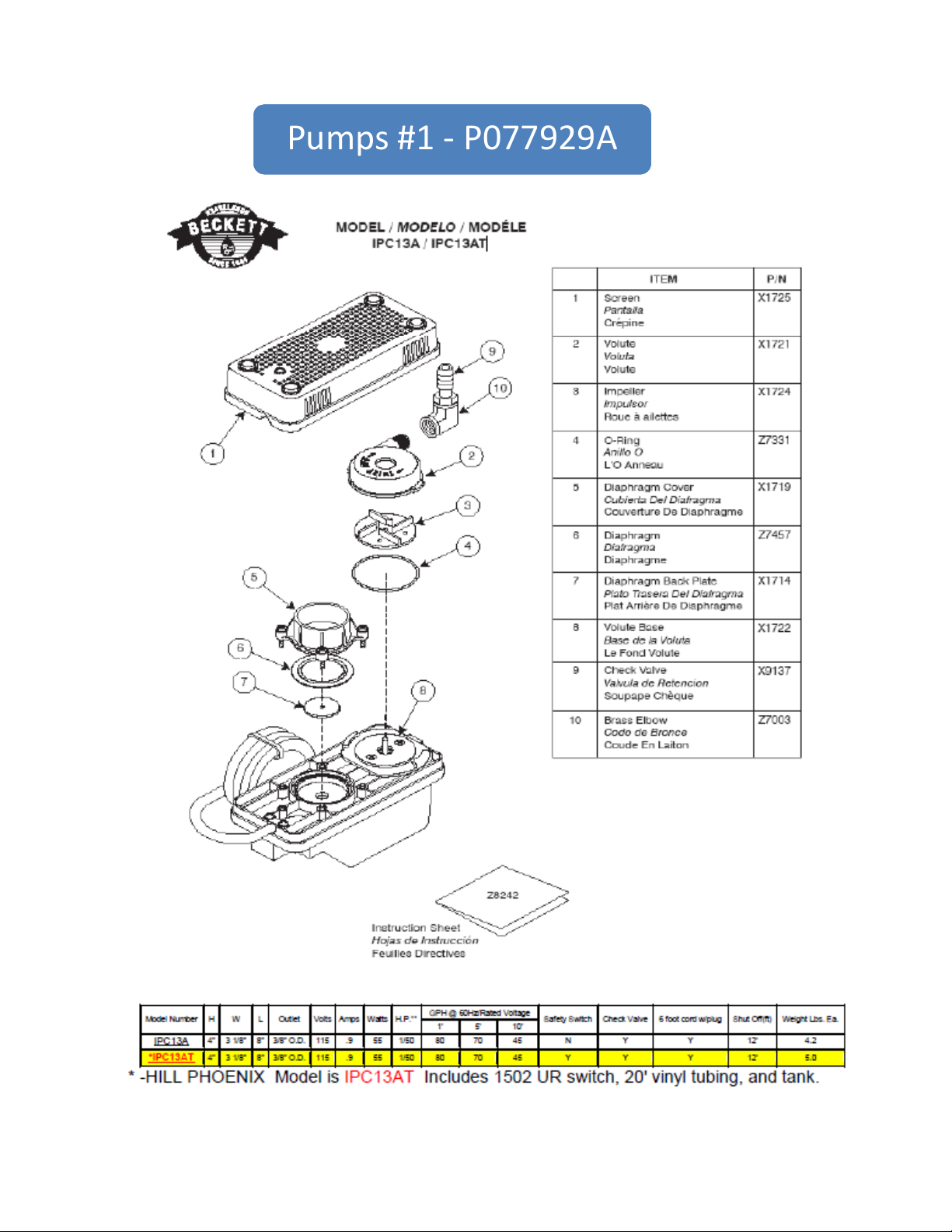
Pumps#1‐ P077929A
PUMP #1 - P077929A

HEA
D -
FEET
0
5
10
15
20
25
30
35
40
45
0 100 200 300 400 500
0. 0
2. 0
4. 0
6. 0
8. 0
10. 0
12. 0
0 500 1000 1500
HEA
D -
METERS
FLOW - GALLONS/HOUR
FLOW -LITERS/HOUR
Specifications
P080674G
PUMP #2 - P080674G
VCL-45 Series
Model
No.
VCL-45ULS 553240 3/8" OD Copper UL/CSA 1/5 115 60 3.5 185 450 445 440 415 380 45 19.5 6 13.00
VCL-45ULS 553245 3/8" OD Copper UL/CSA 1/5 230 50/60 1.0 250 450 445 440 415 380 45 19.5 6 14.00
www.LittleGiantPump.com
Item
No.
Discharge
Size Listing HP Volts Hertz Amps Watts
Performance (GPH @ Head) Shut Off
Replacement Parts
Tank 153502
Cover, Tank 153225
Copper Tubing 938108
Adapter, Brass 941014
Float/Switch Assy 153537
Cover, Switch 153120
Safety Switch Assy 154713
Stand/Volute Assy 153516
Seal Ring 928025
Impeller 153520
PO Box 12010 • Oklahoma City, OK 73157
Phone: 800.701.7894 • Fax: 800.701.8046
E-mail: customerservice@littlegiant.com
Form 995128 — 03/2003
Pwr. Cord
(ft.)
Weight
(lbs.)1' 3' 5' 9' 15' Feet PSI

APPENDIX C:
WIRING DIAGRAMS

FEA ELECTRICAL BOX
R813320 – rev2
WIRING DIAGRAM

SIGHT GLASS
CASE LEFT LED HARNESSCASE RIGHT LED HARNESS
TEMPERATURE PROBES
CONDENSING UNIT
CAPACITOR CABINET
WIRING HARNESS
CONDENSING UNIT
PUMP 2 RECEPTICAL
CONDENSING PUMP TWO
PUMP RECEPTICAL HARNESS
COMPRESSOR
CONTROL PANEL
CONDENSING UNIT
PUMP 1 RECEPTICAL FAN JUNCTION BOX
CONDENSING UNIT

FEA ELECTRICAL BOX

CONDENSING UNIT WIRING DIAGRAM

LED WIRING DIAGRAM

NOTES

NOTES

NOTES

WARRANTY
HEREINAFTER REFERRED TO AS MANUFACTURER
FOURTEEN MONTH WARRANTY. MANUFACTURER’S PRODUCT IS WARRANTED TO BE FREE FROM
DEFECTS IN MATERIAL AND WORKMANSHIP UNDER NORMAL USE AND MAINTENANCE FOR A
PERIOD OF FOURTEEN MONTHS FROM THE DATE OF ORIGINAL SHIPMENT. A NEW OR REBUILT
PART TO REPLACE ANY DEFECTIVE PART WILL BE PROVIDED WITHOUT CHARGE, PROVIDED THE
DEFECTIVE PART IS RETURNED TO MANUFACTURER. THE REPLACEMENT PART ASSUMES THE
UNUSED PORTION OF THE WARRANTY.
This warranty does not include labor or other costs incurred for repairing, removing, installing, shipping, servicing, or handling of either defective parts or replacement parts.
The fourteen month warranty shall not apply:
1. To any unit or any part thereof which has been subject to accident, alteration, negligence, misuse or
abuse, operation on improper voltage, or which has not been operated in accordance with the
manufacturer’s recommendation, or if the serial number of the unit has been altered, defaced, or removed.
2. When the unit, or any part thereof, is damaged by fire, flood, or other act of God.
3. Outside the continental United States.
4. To labor cost for replacement of parts, or for freight, shipping expenses, sales tax or upgrading.
5. When the operation is impaired due to improper installation.
6. When installation and startup forms are not properly complete or returned within two weeks after startup.
THIS PLAN DOES NOT COVER CONSEQUENTIAL DAMAGES. Manufacturer shall not be liable under any circumstances for any consequential damages, including loss of profit, additional labor cost, loss of refrigerant
or food products, or injury to personnel or property caused by defective material or parts or for any delay in its
performance hereunder due to causes beyond its control. The foregoing shall constitute the sole and exclusive remedy of any purchases and the sole and exclusive liability of Manufacturer in connection with this
product.
The Warranties are Expressly in Lieu of All Other Warranties, Express of Implied and All Other Obligations
or Liabilities on Our Part. The Obligation to Repair or Replace Parts or Components Judged to be Defective
in Material or Workmanship States Our Entire Liability Whether Based on Tort, Contract or Warranty. We
Neither Assume Nor Authorize Any Other Person to Assume for Us Any Other Liability in Connection with
Our Product.
MAIL CLAIM TO:
Hill PHOENIX
Display Merchandisers
1925 Ruffin Mill Road
Colonial Heights, VA 23834
1-800-283-1109
Electrical Distribution Products
Hill PHOENIX
Refrigeration Systems &
709 Sigman Road
Conyers, GA 30013
770-285-3200
06/00

Warning
Maintenance & Case Care
When cleaning cases the following must be performed
PRIOR to cleaning:
To avoid electrical shock, be sure all electric power is
turned off before cleaning. In some installations, more
than one switch may have to be turned off to completely de-energize the case.
Do not spray cleaning solution or water directly on fan
motors or any electrical connections.
All lighting receptacles must be dried off prior to insertion and re-energizing the lighting circuit.
Please refer to the Use and Maintenance section of this installation manual.
Tel: 1-800-283-1109
Due to our commitment to continuous improvement, all specifications are subject to change without notice.
1925 Ruffin Mill Road, Colonial Heights, VA 23834
Hill PHOENIX is a Sustaining Member of the American Society of Quality.
Visit our web site at www.hillphoenix.com
BDM0819
 Loading...