

Page 1

January 2019 1000-3960 Revision 1.5
www.hillcrestlabs.com © 2019 Hillcrest Laboratories, Inc. All rights reserved 1 / 17
BNO080 Development Kit for Nucleo
Quick Start Guide
The BNO080 is a System in Package (SiP) that integrates a triaxial accelerometer, a triaxial gyroscope,
magnetometer and a 32-bit ARM® Cortex™-M0+ microcontroller running Hillcrest’s SH-2™ firmware.
This document is intended to provide information about the BNO080 Development Kit, the pin
connections and software provided by Hillcrest to facilitate customer integration.
1. Hardware
1.1. Introduction
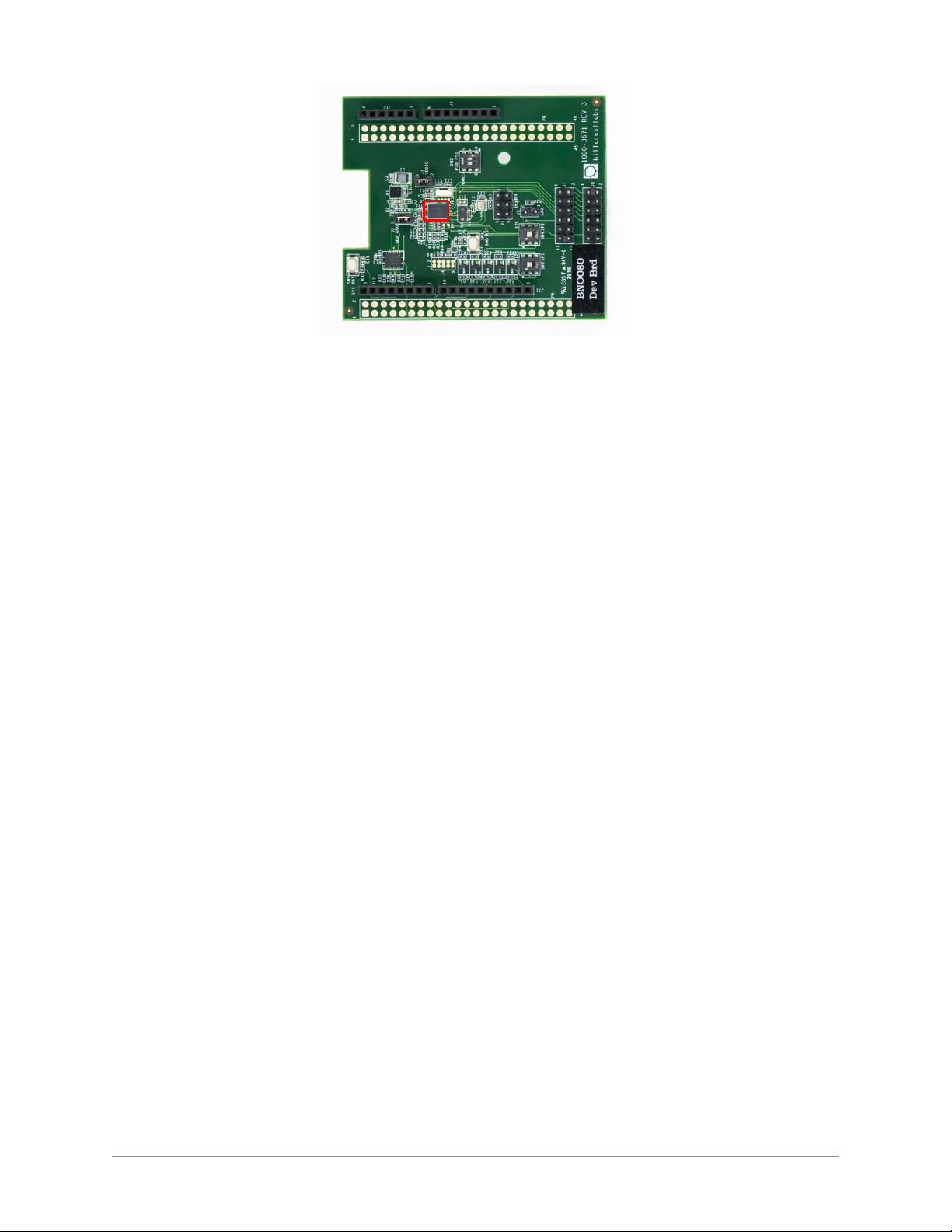
The BNO080 Development Kit includes a shield known as the BNO080 (“target device”) Development
Board that is designed for quick and easy development and prototyping. The shield is designed to
connect to a number of evaluation platforms – one of which is the STM32F4x1RE Nucleo (“bridge
board”) which is developed and sold by STMicroelectronics1 (ST) and is included in the BNO080
Development Kit package. The Nucleo platform includes a STM32F4x1 MCU that serves as the master to
the BNO080. This document includes details for connecting and using the BNO080 Development Kit
with the ST Nucleo prototyping platform.
Figure 1: BNO080 Development Kit with ST Nucleo
1
https://www.st.com/en/evaluation-tools/nucleo-f411re.html
Page 2

January 2019 1000-3960 Revision 1.5
www.hillcrestlabs.com © 2019 Hillcrest Laboratories, Inc. All rights reserved 2 / 17
1.2. Connections
The BNO080 Development Board simply plugs into the Nucleo board and is ready to use. The reader is
encouraged to review the BNO080 Datasheet
[1]
for more information on the pinout configurations. The
BNO080 communicates with a host system over switch selectable serial interfaces.
Dev Board
Signal
Nucleo
J11.1
SCL
CN5.10
J11.2
SDA
CN5.9
J11.3
NC
CN5.8
Dev Board
Signal
Nucleo
J11.4
GND
CN5.7
J9.1
NC
CN6.1
J11.5
SCK
CN5.6
J9.2
VDD_TRGT
CN6.2
J11.6
MISO
CN5.5
J9.3
SYS_RST
CN6.3
J11.7
MOSI
CN5.4
J9.4
VDD_IO
CN6.4
J11.8
CSN
CN5.3
J9.5
NC
CN6.5
J11.9
NC
CN5.2
J9.6
GND
CN6.6
J11.10
NC
CN5.1
J9.7
GND
CN6.7
J9.8
NC
CN6.8
Dev Board
Signal
Nucleo
J12.1
CLKSEL0
CN9.8
Dev Board
Signal
Nucleo
J12.2
WAKE
CN9.7
J10.1
NC
CN8.1
J12.3
NRST
CN9.6
J10.2
NC
CN8.2
J12.4
BOOTN
CN9.5
J10.3
NC
CN8.3
J12.5
INT (opt)
CN9.4
J10.4
NC
CN8.4
J12.6
INT
CN9.3
J10.5
NC
CN8.5
J12.7
NC
CN9.2
J10.6
NC
CN8.6
J12.8
NC
CN9.1
Dev Board
Signal
Nucleo
Note
J7.3
RXD
CN10.21
J7.2
TXD
CN7.21
Note: Nucleo pins are not connected to the BNO080 Dev Board. External wiring is required.
Figure 2: BNO080 Development Board Interface to Nucleo Host device
The BNO080 uses the Sensor Hub Transport Protocol (SHTP) to communicate with a system or
application processor (host that connects to the BNO080). The SHTP protocol is documented in the
BNO080 datasheet, allowing a customer to potentially develop their own host software if they choose to
do so. In order to ease customer integration, Hillcrest has developed software that runs on a host
platform such as the STM32F4x1RE Nucleo series. The software driver fully implements the
communication protocol used by the BNO080. Hillcrest provides this software driver package as source
code. The BNO080 Development Kit has programmed the ST Nucleo to work with the Hillcrest PC
application to demonstrate functions. Customers who intend to use the BNO080 Development Kit for
their own software development should use the driver package to download a new firmware.
Page 3

January 2019 1000-3960 Revision 1.5
www.hillcrestlabs.com © 2019 Hillcrest Laboratories, Inc. All rights reserved 3 / 17
1.3. Switch Configurations
There are several switches on the board which are used to configure the hardware to select the protocol
for communication with the host. The board is shipped with the I2C interface setting as the default
configuration.
The communication interface is configured by setting the protocol selection SW2 (PS0/1) pins and SW4,
SW6 appropriately.
PS1
PS0
BNO080
Transport
Protocol
0 0 I2C
0 1 UART-RVC
1 0 UART-SHTP
1 1 SPI
Figure 3: BNO080 Available Selection of Host Communication Interface
SW2
PS0
SW2
PS1
SW4
SPI
SW6
SPI
BNO080
Transport
Protocol
0 0 0 0 I2C
1 1 1 1 SPI
0
1
Don’t
care
1
UART-SHTP
Figure 4: Selection of Host Communication Interface in BNO080 Development Board
Figure 5: Default Switch Configuration for I2C
Page 4
January 2019 1000-3960 Revision 1.5
www.hillcrestlabs.com © 2019 Hillcrest Laboratories, Inc. All rights reserved 4 / 17
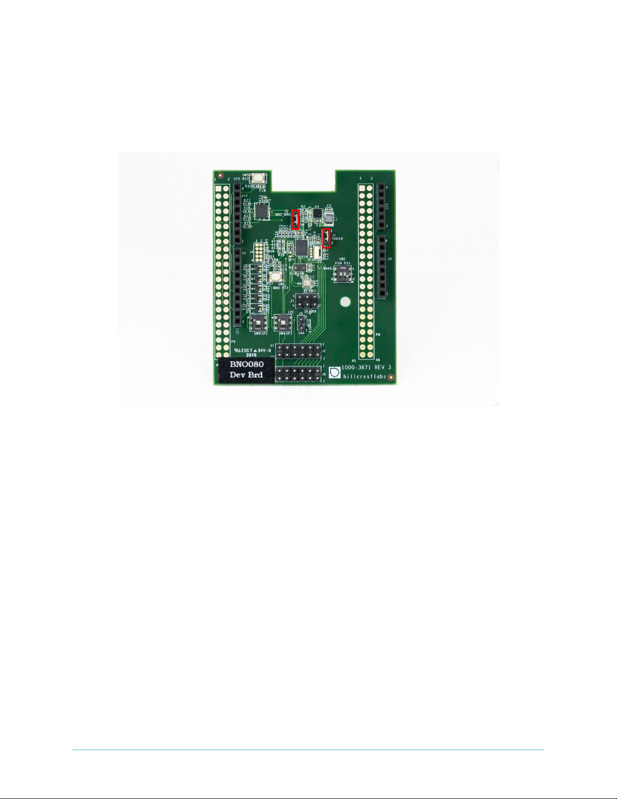
1.4. Power Measurement Headers
Two headers are available to provide an easy way to measure the current usage of the BNO080 device.
J1 is for VDDIO and J2 is for VDD. These two jumpers must be installed for normal use. If you need to
measure the current you should remove the jumper and install a current meter.
Figure 6: Power Measurement Headers
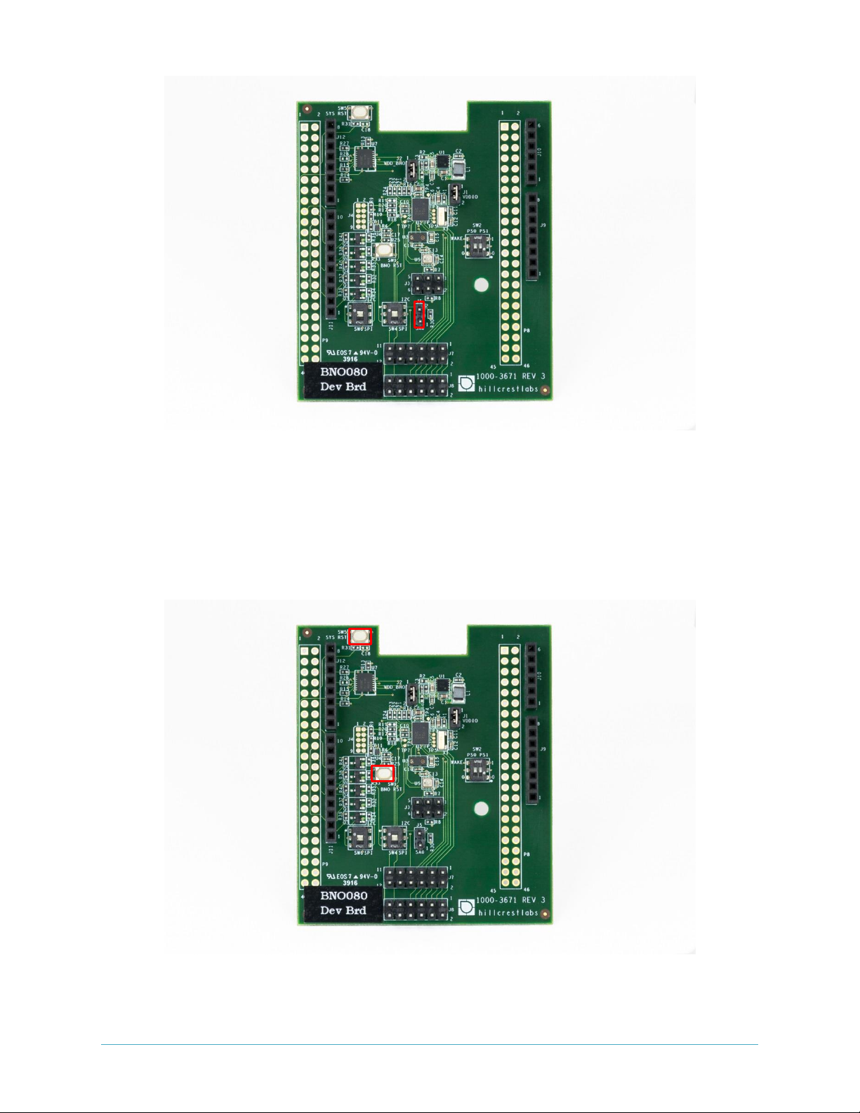
1.5. Slave Address Selection for I2C Host Interface
The default slave address is 0x4A when SA0 is low (no jumper installed on J5). The slave address is 0x4B
when SA0 is high (jumper installed on J5).
Page 5
January 2019 1000-3960 Revision 1.5
www.hillcrestlabs.com © 2019 Hillcrest Laboratories, Inc. All rights reserved 5 / 17
Figure 7: Slave Address Selection for I2C Host Interface
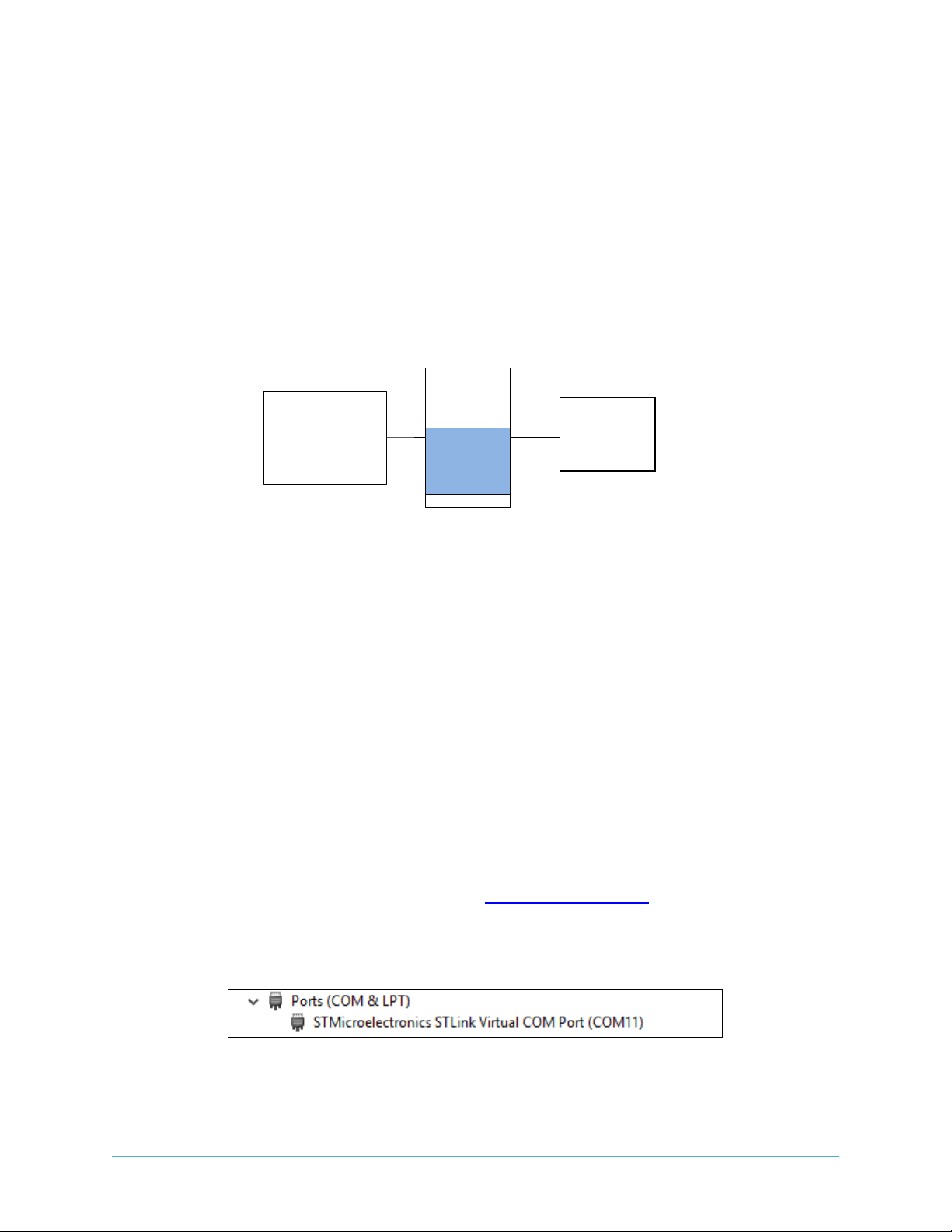
1.6. Reset Buttons
Two reset buttons are available. SW1 will reset the BNO080 and SW5 will reset the Nucleo.
Figure 8: Reset Buttons
Page 6
January 2019 1000-3960 Revision 1.5
www.hillcrestlabs.com © 2019 Hillcrest Laboratories, Inc. All rights reserved 6 / 17
2. Software
2.1. BNO080 Development Kit
BNO080 Development Kit contains a pre-programmed STM32 Nucleo board with Hillcrest software that
allows communication between the BNO080 and Freespace™ MotionStudio 2.
Freespace™ MotionStudio 2 is a Windows application to allow users to control and configure the
BNO080 through a USB interface. BNO080 Development Kit can be used for a quick evaluation of the
BNO080. A generalized system diagram is shown in Figure 9.
Figure 9: Simplified System Diagram with Freespace™ MotionStudio 2
2.2. Running a PC Demo Application with BNO080 Development Kit
2.2.1. Requirement
Running Freespace™ MotionStudio 2 with BNO080 development kit requires the following items.
• ST-LINK/V2 USB driver available from the ST website (http://www.st.com/en/embedded-
software/stsw-link009.html).
• ST32 Virtual COM Port Driver from ST website (http://www.st.com/en/development-
tools/stsw-stm32102.html). The BNO080 software package is tested with STSW version 1.5.0.
Once you downloaded and extracted the driver, follow the readme.txt file for the instruction to
complete the installation.
• Freespace™ MotionStudio 2 application from http://hillcrestlabs.com
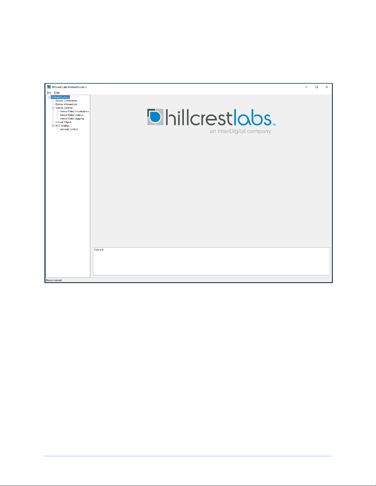
Connect USB Type A to Mini-B cable to Nucleo board and your PC. The virtual COM port should appear
in your Device Manager.
Figure 10: Device Manager to Check Installed Driver for ST Virtual COM Port
Start Freespace™ MotionStudio 2 (MotionStudio2.exe) after BNO080 development kit virtual COM port
is successfully detected in your PC.
Nucleo
Windows PC
MotionSutdio 2
(executable)
Bridge
(binary)
Preloaded
BNO080
Dev Brd
Page 7
January 2019 1000-3960 Revision 1.5
www.hillcrestlabs.com © 2019 Hillcrest Laboratories, Inc. All rights reserved 7 / 17
2.2.2. Running PC Application
Start Freespace™ MotionStudio 2
After you unzip the PC Application package, launch MotionStudio2.exe under MotionStudio2 folder. This
will open MotionStudio2 window.
Figure 11: Startup Window of Freespace™ MotionStudio 2
Establish Connection to the Nucleo Board
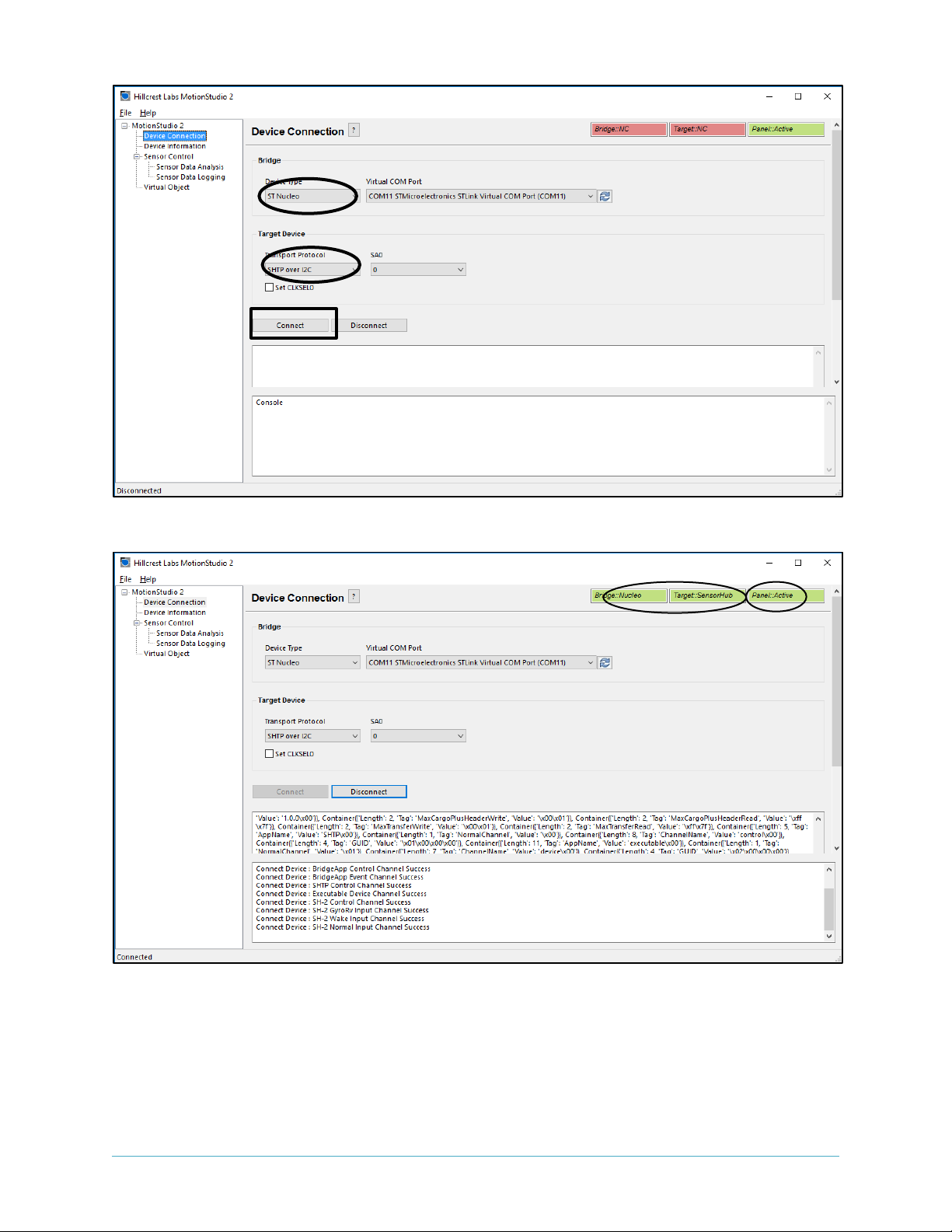
From the menu panel on the left, select Device Connection. This panel allows users to select device type,
transport protocol and more.
• “Device Type” of the bridge is set to ST Nucleo.
• ST Link Virtual COM Port available in your PC appears in “Virtual COM Port” box.
• “Target Device” is set to SHTP over I2C by default. Check SW2/SW4/SW6 settings for transport
protocol selection. Refer to Section 1.3.
• “SA0” is set to 0. Check J5 jumper settings for I2C address selection. Refer to Section 1.5.
• Use “Connect” button to start.
Page 8
January 2019 1000-3960 Revision 1.5
www.hillcrestlabs.com © 2019 Hillcrest Laboratories, Inc. All rights reserved 8 / 17
Figure 12 Device Connection Panel in Freespace™ MotionStudio 2
Figure 13: Device Connection Window after Successful Communication in Freespace™ MotionStudio 2
When connection process is completed, the three status indicator text boxes on the upper right hand
corner of the panel and the console window on the bottom would provide the result of connection
process. The three status indicators show the status of the connected system and the status of the
associated panel. If the specific panel supports the protocol used by the connected device, the panel
becomes active and shows in green color.
Page 9
January 2019 1000-3960 Revision 1.5
www.hillcrestlabs.com © 2019 Hillcrest Laboratories, Inc. All rights reserved 9 / 17
Sensor Control
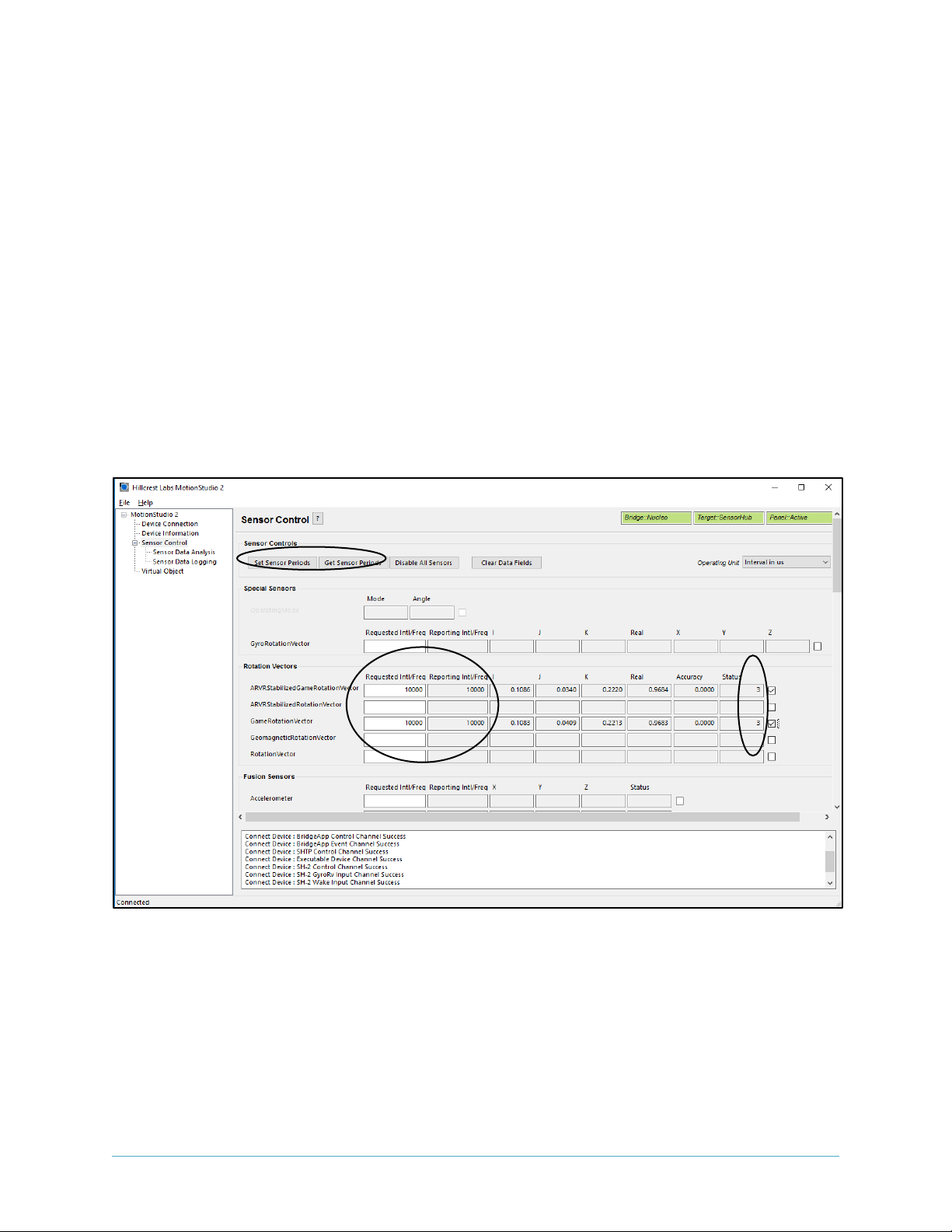
The Sensor Control panel allows the users to enable and disable the various sensors individually. There
are two ways to control sensors:
• To enable an individual sensor at a default operation rate, use the check box on the right end of
the row for each sensor.
• To enable sensors at specific rates, input the requested operation period, in microseconds, in
the 'Requested Period (us)" fields. Then click the "Set Sensor Periods" button on the top of the
panel. All sensors will be updated with specified operating period. The "Requested Period (us)"
fields which are left blanked or obtained invalid value are assumed to be "zero".
In many cases, the sensors do not operate at the exact rate as requested. The actual operating period is
shown in the "Reported Period (us)" field. Users can also use the "Get Sensor Periods" button on top of
the panel to refresh the actual operating period for all sensors.
Figure 14: Sensor Control Panel in Freespace™ MotionStudio 2
Virtual Object
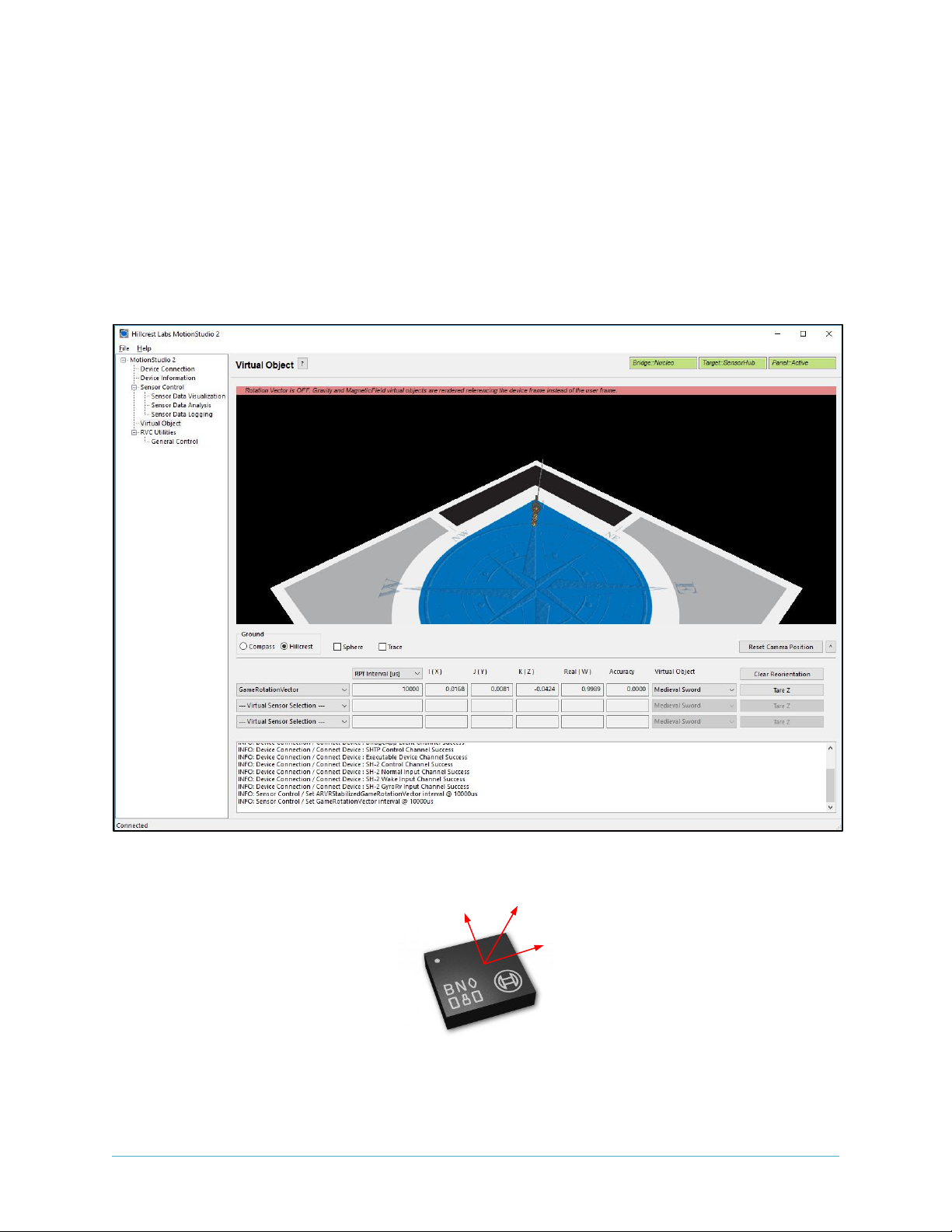
Virtual Object panel shows the orientation of the device. Please note that you need to enable sensors in
Sensor Control panel, select the sensor from the drop down menu in Virtual Object panel. The sword in
the Virtual Object will move according to the device orientation.
Page 10
January 2019 1000-3960 Revision 1.5
www.hillcrestlabs.com © 2019 Hillcrest Laboratories, Inc. All rights reserved 10 / 17
To adjust the camera position, move the cursor to the Virtual object Panel, then press the LEFT mouse
button. Hold the button down and move the mouse to change the view position. To reset the camera
position, use the "Reset Camera Position" button.
To display the game rotation vectors, select the game rotation vectors from the drop down menu, the
data fields should start updating with the received sensor data. The virtual object will move according to
the orientation of the hardware. Use the Sensor Control Panel to enable or disabl the specific sensor.
This panel does not control the sensor but displays the output data.
Figure 15: Virtual Object Panel in Freespace™ MotionStudio 2
Y+
X+
Z+
Page 11
January 2019 1000-3960 Revision 1.5
www.hillcrestlabs.com © 2019 Hillcrest Laboratories, Inc. All rights reserved 11 / 17
Figure 16: BNO080 Device Orientation
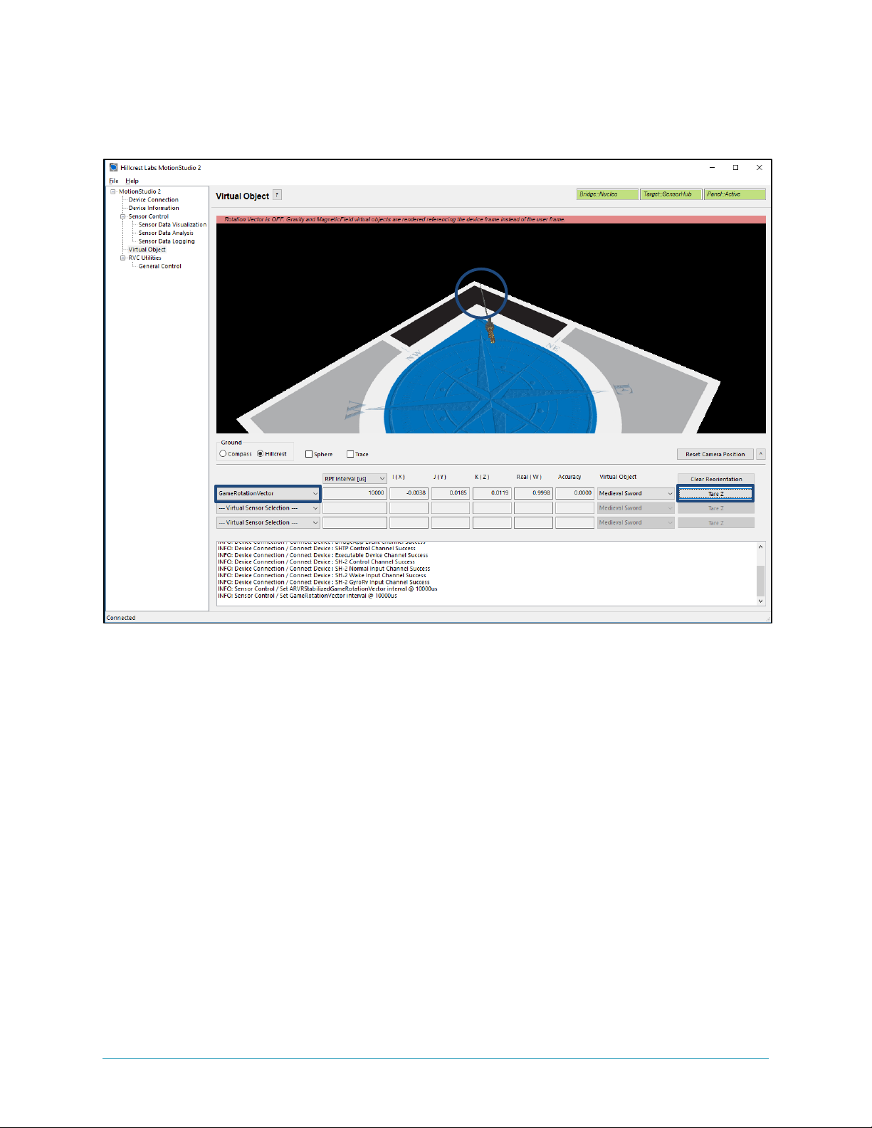
Please follow the instruction below to align your device.
• Enable Game Rotation Vector and ARVR Stabilized Game Rotation Vector in “Sensor
Control” panel.
• Switch to Virtual Object panel and move the background so the black corner of the Hillcrest
logo on the ground plane points to your forward direction (heading).
• Hold the BNO080 development kit Y+ axis points to your forward direction as well.
• Select “Game Rotation Vector” in drop down menu and click “Tare Z”. Now, sword will point
to the edge of the Hillcrest log and is aligned with your device Y+.
Page 12
January 2019 1000-3960 Revision 1.5
www.hillcrestlabs.com © 2019 Hillcrest Laboratories, Inc. All rights reserved 12 / 17
• Switch to “ARVR Stabilized Game Rotation Vector” in drop down menu to evaluated ARVR
Stabilized Game Rotation Vector.
Figure 17: Sensor Orientation in Virtual Object Panel in Freespace™ MotionStudio 2
2.2.3. Backup Bridge Image
Please keep in mind that BNO080 Development Kit is programmed to work with a Windows PC
Application. Development example code explained in the Section 2.3 is different and will over write
the binary image shipped with the BNO080 Development Kit. If you want to switch back to the
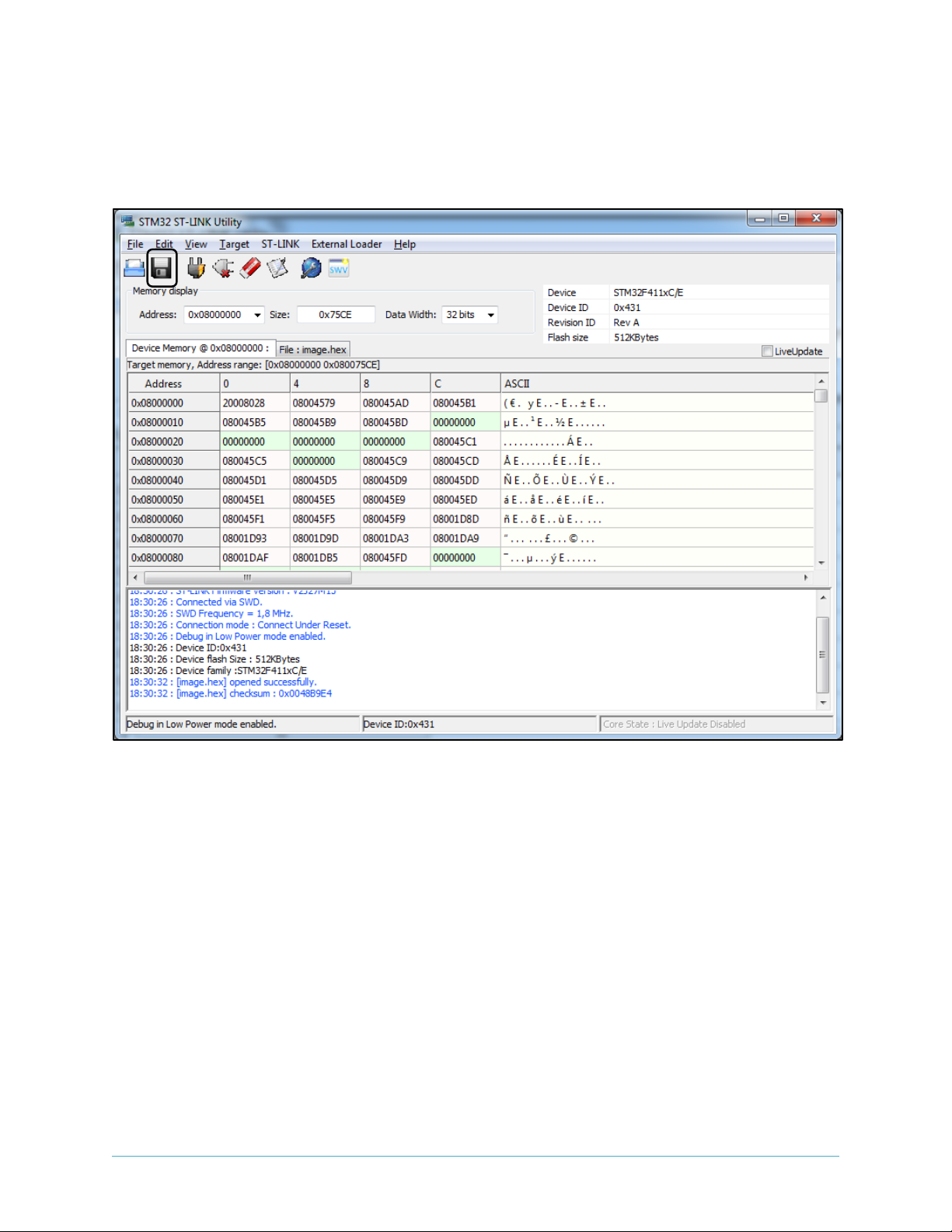
bridge code to run the Windows PC Application, please read the Nucleo device memory using
STM32 ST-LINK Utility before downloading a new image into the Nucleo board. Please follow the
instructions below to back up the prebuilt bridge image.
To save the contents of Nucleo bridge board:
• Open STM32 ST-LINK Utility
• Target->Connect
• Use “Save the displayed content in a Binary File” on the top left corner to save the image
into a file for future use.
To program Nucleo bridge board with the saved image:
• Open STM32 ST-LINK Utility
Page 13
January 2019 1000-3960 Revision 1.5
www.hillcrestlabs.com © 2019 Hillcrest Laboratories, Inc. All rights reserved 13 / 17
• Target->Connect
• Target->Program
• In new window select “File path” to locate previously saved file.
• Click “Start”
Figure 18: STM32 ST-LINK Utility Window
2.3. Development Environment
The example software requires the following items to execute.
• IAR Embedded Workbench® for ARM (EWARM) by IAR Systems.
• ST-LINK/V2 USB driver. This driver is available from the ST website and is supported by the IAR
Embedded Workbench for ARM (EWARM). After installing EWARM, check
IAR_INSTALL_DIRECTORY\arm\drivers\ST-Link\ Please skip this step if you have installed already
from Section 2.2.1.
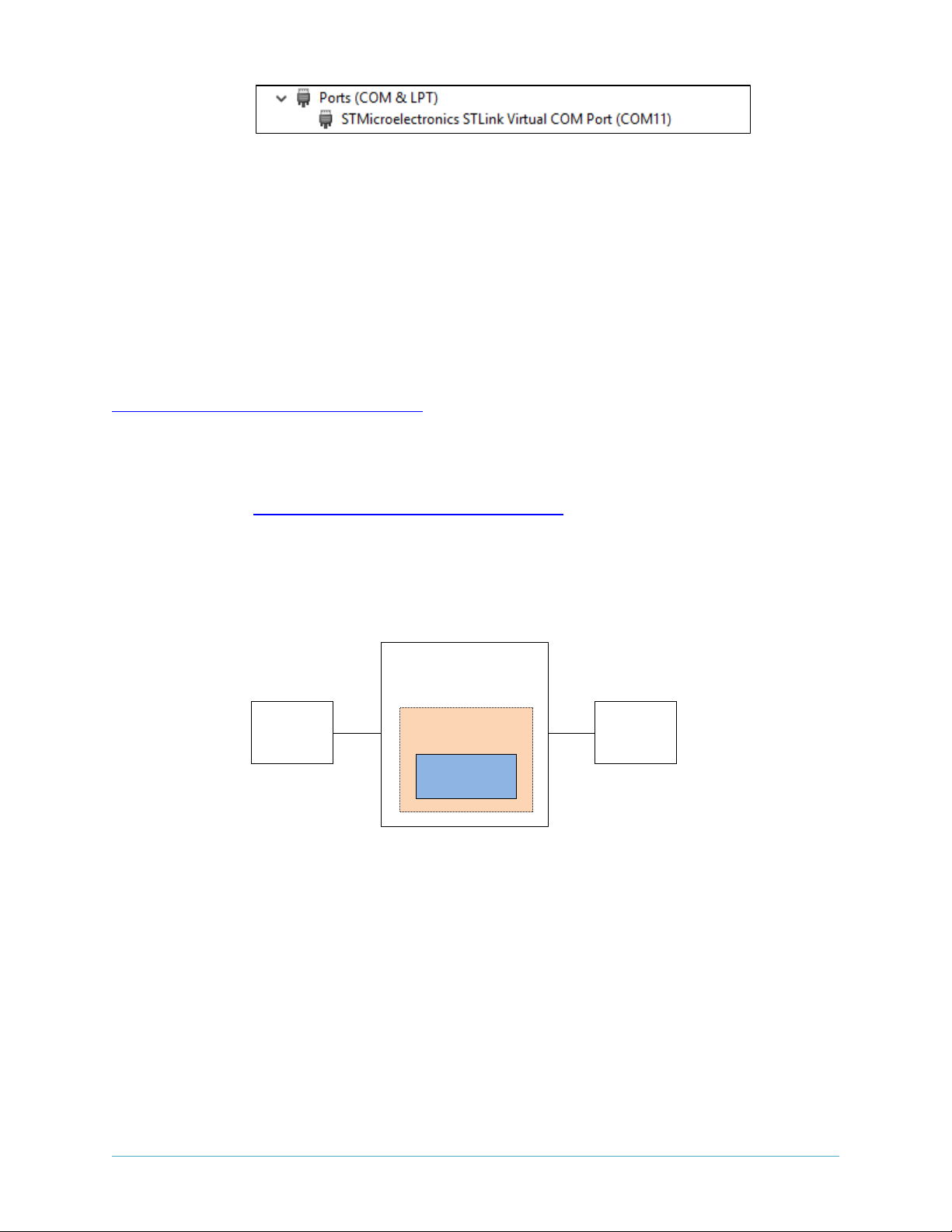
• ST32 Virtual COM Port Driver from the ST website. Please skip this if you have installed already
from Section 2.2.1.
Page 14
January 2019 1000-3960 Revision 1.5
www.hillcrestlabs.com © 2019 Hillcrest Laboratories, Inc. All rights reserved 14 / 17
Figure 19: Installed driver for ST Virtual COM port
• Terminal emulator software like Tera Term or PuTTy. Set up the terminal emulator at 115200 –
8bit – no parity – 1bit stop bit – no flow control.
2.4. Example Software
Hillcrest provides a complete software package for the STM32F4x1RE Nucleo boards.
The example application for BNO080 development kit source code is available in public github.
https://github.com/hcrest/sh2-demo-nucleo
Clone this repository using the --recursive flag with git. Alternatively, you can download a ZIP file from
the link.
git clone --recursive https://github.com/hcrest/sh2-demo-nucleo
Everything required to obtain outputs from the BNO080 is included in this package. The software
package incorporates the BNO080 sensor hub driver, enabling SH2 functionality for the development
system.
Figure 20: Simplified System Diagram (blue indicates driver developed by Hillcrest)
PC
BNO080
Nucleo
SW Framework
MCU Driver
Page 15
January 2019 1000-3960 Revision 1.5
www.hillcrestlabs.com © 2019 Hillcrest Laboratories, Inc. All rights reserved 15 / 17
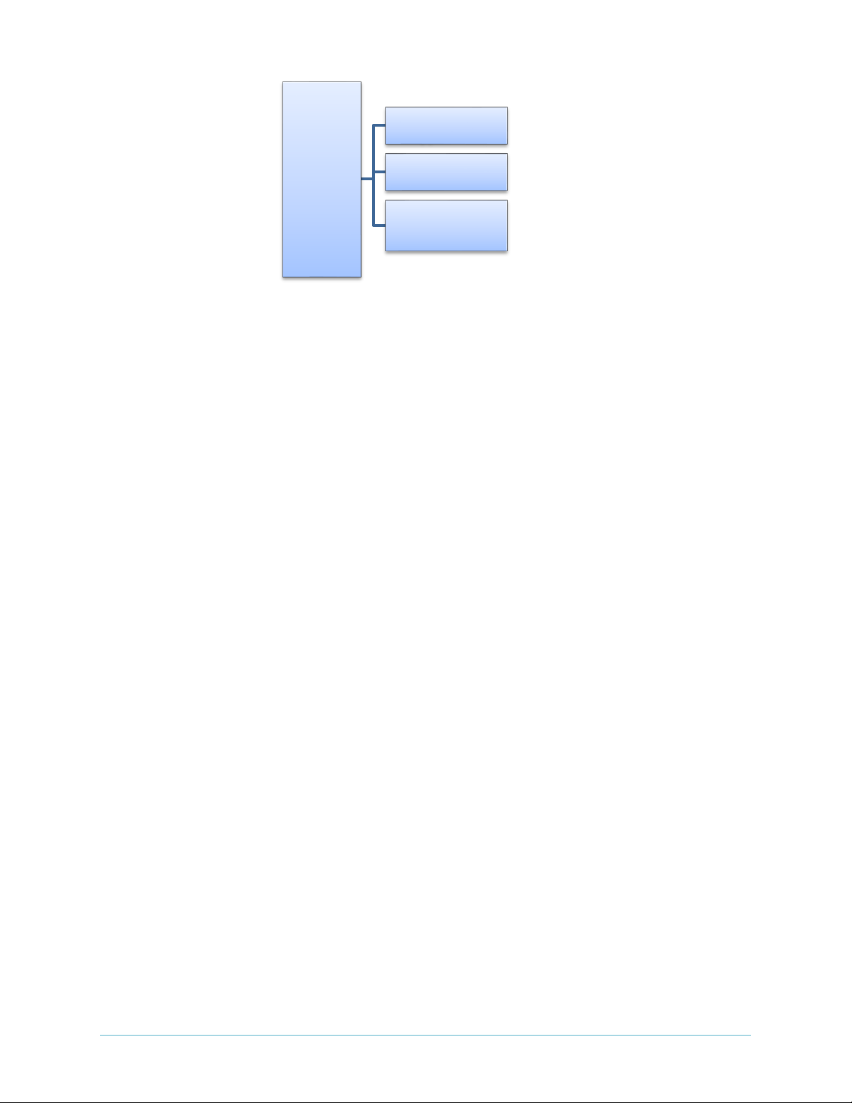
Figure 21: Source Code Structure
The software is organized as an IAR EWARM project that can be dropped into the IAR IDE on a Windows
PC. Follow this procedure to compile the project and download the software to the Nucleo board.
• Open IAR Embedded Workbench for ARM (EWARM) version 7.x
• In the File menu, select Open and choose Workspace. Browse to where the example package is
extracted and select “sh2-demo-nucleo/EWARM/Project.eww”. This should open an IAR
workspace with all the files within the project.
• Select demo-i2c, demo-spi or demo-uart in the project configuration based on the board
settings of SW2/SW4/SW6. Refer to Section 1.3.
• In the “Project” menu, select “Rebuild All” to compile the project.
• After the project is successfully compiled, go to the Project menu and select Download and
Debug.
The “sh2” directory contains a full implementation of the Hillcrest communications protocol for the
BNO080 and User’s Guide for Hillcrest’s SH-2™ driver.
The reader is encouraged to review the BNO080 datasheet
[1]
and the SH-2 Reference Manual
[2]
for
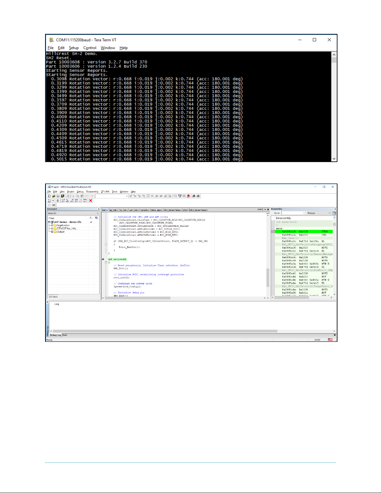
details on how to construct messages. The output from the BNO080 is printed through the serial port.
The first few lines indicate that the host has established proper communication (“Product ID Request”)
with the BNO080 and the BNO080 has responded with version information (“Product ID Response”).
Rotation vector is enabled at 100Hz by default and reports are printed through the serial port.
sh2
-demo
-nucleo
Nucleo Example
Application
ST Drivers
SH2 Driver
Page 16
January 2019 1000-3960 Revision 1.5
www.hillcrestlabs.com © 2019 Hillcrest Laboratories, Inc. All rights reserved 16 / 17
Figure 22: Terminal Emulator Screenshot
Figure 23: IAR EWARM Screenshot
References
1. 1000-3927 BNO080 Datasheet, Hillcrest Labs
2. 1000-3625 SH-2 Reference Manual, Hillcrest Labs
3. 1000-3600 SH-2 SHTP Reference Manual, Hillcrest Labs
Copyright © 2019 Hillcrest Laboratories, Inc. All rights reserved.
Page 17

January 2019 1000-3960 Revision 1.5
www.hillcrestlabs.com © 2019 Hillcrest Laboratories, Inc. All rights reserved 17 / 17
Notices
Information furnished by Hillcrest Laboratories, Inc. (Hillcrest) is believed to be accurate and reliable.
However, Hillcrest assumes no responsibility for its use, nor for any infringement of patents or other
rights of third parties that may result from its use.
Hillcrest reserves the right to make changes, corrections, modifications or improvements to this
document at any time without notice. Information in this document supersedes and replaces all
information previously supplied. Hillcrest makes no warranties, express or implied, regarding the
information contained in this document.
Information in this document is provided solely to enable the use of Hillcrest products. “Typical”
parameters provided by Hillcrest are not guaranteed, and can vary between applications and over time.
The product is designed primarily for use in consumer electronics and has not been evaluated for use in
products or systems where failure or malfunction may result in personal injury, death, severe property
damage or environmental damage, such as aerospace, life saving, life sustaining or military applications.
Hillcrest assumes no liability for any claims or damages arising from information contained in this
document, or from the use of products and services detailed herein. This exclusion includes, but is not
limited to, claims or damages based on the infringement of patents, trademarks, copyrights and/or any
other intellectual property rights. The product is provided by Hillcrest “As Is.” Hillcrest makes no
representations or warranties regarding the product express or implied, including without limitation any
implied warranties as to title, noninfringement, merchantability, or fitness for a particular purpose.
Freespace is a registered trademark of Hillcrest Laboratories, Inc. The Hillcrest Labs logo is a trademark
of Hillcrest Laboratories, Inc. All other trademarks and copyrights are the property of their respective
owners.
“Third party notices are available on our website at: http://hillcrestlabs.com/legal/third-party-
attributions/”
 Loading...