

Page 1
RevA 12-2013
Page 2
Welcome
Thank you for choosing Hill Audio for your sound system. To make sure that this product meets your
expectations and provides long-term, reliable performance, please read and follow this instruction
manual carefully.
Important safety instructions
Read these instructions and all markings on the product. Keep these instructions.
Heed all warnings and instructions, both in this manual and on the product.
Clean only with a dry cloth. Unplug from AC supply before cleaning.
Do not use this product near water and avoid any exposure to water.
Before connecting this product to any AC supply, make sure you check whether the AC mains voltage and frequency match the indication on the product and its packaging.
Only connect this product to an AC supply with sufficient power handling, protective earth connection, ground-fault (earth-fault) protection and overload protection.
Disconnect the product from the AC supply during thunderstorms. Also disconnect from the mains
supply if the product is not being used for long periods.
Make sure any heat sink or other cooling surface, or any air convection slot , is exposed sufficiently
to free air circulation and is not blocked.
Do not operate this product in environmental temperatures exceeding 35 degrees Celsius and/or
85% relative humidity.
Position the product in a safe and stable place for operation, out of reach of unauthorized persons.
Make sure any cable connections to and from the product are neither subject to potentially destructive mechanical impact nor present any risk of stumbling or other accident risk to people.
Audio equipment may generate sound pressure levels sufficient to cause permanent hearing
damage to persons. Always start up at low volume settings and avoid prolonged exposure to sound
pressure levels exceeding 90 dB.
Do not open this product for service purposes. There are no user-serviceable parts inside.
Warranty will be void in any case of unauthorized service by the user or other unauthorized persons.
Take any precaution required by local law, applicable regulations or good business practice to avoid
injury to people or material damage by use of this product.
Explanation of symbols used in this manual and on the product:
DANGER!
Safety hazard.
Risk of injury or death.
WARNING!
Fire hazard.
WARNING!
Hazardous voltage.
Risk of severe or fatal
electric shock.
ATTENTION!
Read manual
before installation
and operation.
Manual Language
UK This user manual is written in English. For other languages, visit www.hill-audio.com
FR Ce guide est écrit en anglais. Pour les autres langues, visitez: www.hill-audio.com
DE Diese Anleitung ist in Englisch verfasst. Für andere Sprachen: www.hill-audio.com
ES Este manual está escrito en Inglés. Para otros idiomas, visite: www.hill-audio.com
PT Este manual está escrito em Inglês. Para outros idiomas, visite: www.hill-audio.com
IT Questo manuale è scritto in inglese. Per altre lingue, visitare: www.hill-audio.com
PAGE 1
USER MANUAL - IPA200 INSTALLATION AMPLIFIER
Page 3
PAGE 2
Health advice
This unit produces and absorbs electromagnetic radiation. The strength of radiation and the sensitivity for disturbing interference matches the CE and FCC requirements. A corresponding sign is printed
on the backside of the unit. Any change or modification may affect the behavior of the unit concerning
electromagnetic radiation and it may not then meet CE requirements. The manufacturer takes no
responsibility in this case.
Functional advice
This unit is immune to the presence of electromagnetic disturbances – both conducted and radiated
- up to a certain level. Under peak conditions, the unit is classified to show a “class C” performance
criteria and may encounter temporary degradation or loss of function which may need manual help
to recover. In such case, disconnect the AC power from the unit and reconnect it again to recover.
Environmental advice
This unit is built to conform to the ROHS standards and the WEEE directive 2002/96/EC of the
European Parliament and of the Council of the European Union. Under these regulations, the product
shall not be discarded into regular garbage at the end of its life, but shall be returned to authorized
recycling stations.
Unpacking
Please check that the box contains the following items:
Main parts: 1 pc. IPA200 main unit
1 pc. Mains cable
1 pc. Operation manual
If any part is missing, please contact your dealer immediately.
Warning
After unpacking, and before plugging the AC cord in the wall outlet, check whether the
AC mains voltage and frequency is compatible with this product (see rear panel of
product). Whenever the specified voltage or your AC plug should not match the local
conditions, do NOT plug the AC cord into the wall outlet and contact your dealer
immediately.
Description
The IPA200 is a stereo power amplifier for background music or studio monitoring applications,
which is user-configurable to work in stereo or parallel mono mode. It offers additional filters and
equalizers to adapt perfectly to the connected speakers, and can be set up in a tamper-proof way with
its front-panel volume controls disabled. Providing Hifi-Sound from a quiet, convection-cooled design,
it offers pristine audio quality even in quiet environments. From desktop audio to zone amplification,
this amplifier provides every-day reliability for audio systems of any size.
USER MANUAL - IPA200 INSTALLATION AMPLIFIER
Page 4
PAGE 3
USER MANUAL - IPA200 INSTALLATION AMPLIFIER
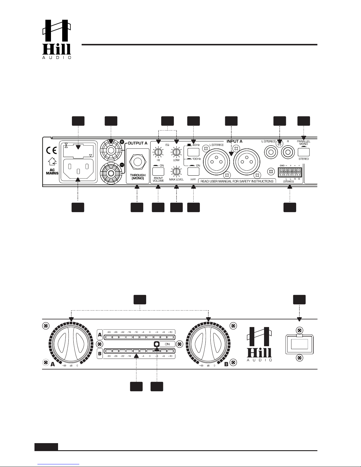
Controls and Connections
Connections - Rear (Outputs)
Controls - Front
Note: Illustration shows channel A controls only. Channel B controls and connections are the same.
1
2
3
4
5
8
9
11
10
12
13
15 16
14 17
R
6
7
Page 5

PAGE 4
USER MANUAL - IPA200 INSTALLATION AMPLIFIER
Functional Description
The IPA200 is a convection-cooled stereo installation amplifier with a flexible input section to adapt it
to both stereo and dual mono applications with low-impedance speaker systems from full range to
limited frequency response,. The flexibility of the inpout section makes the IPA200 the right choice for
both full range background music systems as well as speech-range paging systems, both in main and
zone applications.
2
1
3
AC inlet. Use the supplied AC cord to connect the unit to AC mains. Make sure voltage and
frequency stated on the unit comply with your local AC supply.
Fuse drawer. To change the mains fuse, unplug the AC cord first, pull out the fuse drawer and
replace the fuse ONLY with a fuse of SAME voltage and rating. If the fuse blows again after
replacement, hand over the unit to qualified service personnel.
Speaker Outputs. Connect your speakers to these outputs. Note that these are low-impedance
outputs, not suitable to connect speaker with built-in 100V line transformers. Make sure that
the speakers or any combination of speakers have a minimum nominal impedance of 4 Ohms.
Avoid any short circuits between the plus and minus poles of the outputs, and be aware that
these outputs may carry voltages which represent a risk of electric shock. Consequently, only
connect your speakers when the unit is switched off.
Through connector. This connector carries the same signal as fed into the internal amplifier
blocks of the unit. This means that in case the switch (13) is set to “Stereo”, the through
connector (4) will carry the input signals of channel A and B independently, while in case the
switch (13) is set to “Parallel Mono” both through connectors will carry the input signal of
channel A.
Balanced channel A and B inputs. These are stereo inputs, which are internally summed to
mono. If the signal is alread a mono signal, or just one channel of a stereo signal, the L socket
shall be used for channel A and the R socket for channel B. Providing a stereo input is useful if
your feeding source is stereo but you wish to use it for a mono speaker zone. This way, the
IPA200 can for example be used as a regular stereo amplifier by feeding a stereo source’s
two outputs into channel A’s L socket and channel B’s R socket, and setting the switch (13) to
“Stereo”. The IPA200 can also be used as a dual mono zoner being fed from one stereo
source, with connecting the source to channel A’s L and R inputs, switching (13) to “Parallel
Mono” and then being able to adjust the levels for both outputs independently.
Balanced plug terminal channel A and B inputs. Same function as (5) with a standard 3.5mm
“Phoenix”-style plug terminal socket.
Unbalanced channel A and B inputs. Same function as (5) but unbalanced configuration with
RCA connectors.
HP (High Pass) Filter on/off switch. Engages or disengages the internal high pass filter. Engaing this filter can help to remove low frequency energy from the output signal, which can help
if the connected speaker system consists of speakers with limited low-frequency response like
very small cabinet speakers or open-back ceiling speakers. The roll-off frequency can be
chosen via switch (9).
HP filter roll-off frequency selector. Switches between a 40Hz and a 100Hz roll-off point in
case the switch (8) is engaged.
Equalizer. Allows the adjustment of the tonal balance for the channel A and B output signal
independently in two music-specific frequency bands with an adjustment range of ±12dB.
4
9
10
7
8
6
5
Page 6
PAGE 5
USER MANUAL - IPA200 INSTALLATION AMPLIFIER
11
12
13
14
15
Maximum level setting. This control allows to limit the maximum level of channel A and B independently in order to match the connected sound system. Adjustments made on this control
will will limit the adjustment range of the front-panel volume controls (14). Note that settings
shall be made with a small screw driver; the total angle is 300 degrees; do not apply excessive
force with the screw driver.
Front volume control enable/disable switch. In certain installation situations, it may be sensible to avoid operators being able to change volume settings. Pressing this switch will disable
the front volume controls (14), making all level adjustments only depending on the rear-panel
maximum level controls (11).
Operation mode switch. Determines the signal routing inside the unit between two options.
Either the Channel A and B input signals are routed independently to the internal amplifier
blocks A and B (setting “Stereo”) or only the channel A input signal is routed to both internal
amplifier blocks A and B (setting “Parallel Mono”).
Front volume controls. Provided the switch (12) is engaged, these controls determine in combination with the rear maximum level setting controls (11) the total volume for each channel.
If the switch (12) is not engaged, these controls are disabled.
Output level meters. Display the output level.
Power indicator. Indicates whether the unit is switched on or off.
Power switch. Switches the unit on and off.
16
17
Operation
A1. Connections: AC
For connecting this unit to AC mains, please note:
Check whether the AC mains voltage and frequency is the same as this product is specified for
(see rear panel of product). Whenever the specified voltage or your AC plug should not match the
local conditions, do NOT plug the AC cord into the wall outlet and contact you dealer immediately.
Do not operate this unit without the line cord earth ground connected. To do so may increase the
risk of electric shock and increase line cord conducted emissions.
A2. Connections: Input signals
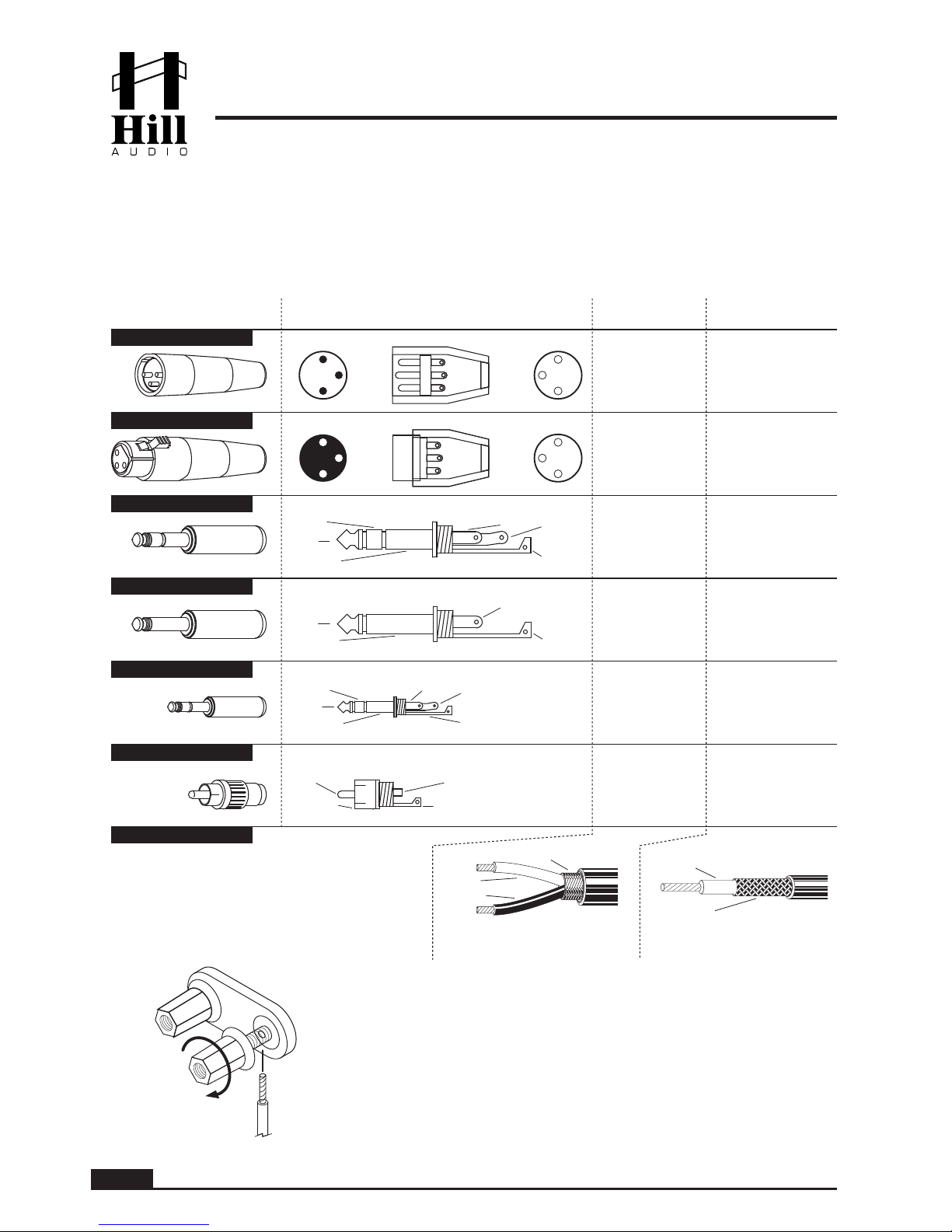
Good and reliable connections are a basic requirement for good sound and reliable operation, hence
always use good cables. In case of doubt about making proper connections, please see check the
standard pin assignments required for proper operation shown below
A3. Connections: Speaker cabling
The choice of suitable speaker cables is an essential point of amplifier installation. Speaker cables,
specifically long ones, can significantly contribute to the load impedance of the amplifier, thus reducing the power output and turning some of the output power into heat instead of delivering it to the
speakers. The most important aspect is to keep cables as short as possible and to choose a sufficient
copper cross-section, with maximum length values as per below:
Cross-Section AWG 8 Ohms
0.75 mm
2
18 4.00 m
1.5 mm
2
15 8.00 m
2.5 mm
2
13 14.00 m
4.0 mm
2
11
6 Ohms
3.00 m
6.00 m
10.50 m
15.00 m 20.00 m
4 Ohms
2.00 m
4.00 m
7.00 m
10.00 m
Page 7
PAGE 6
USER MANUAL - IPA200 INSTALLATION AMPLIFIER
B. Powering up
Following a proper power-up sequence protects your equipment – specifically speakers – and your
ears. Follow the below procedure:
Turn down all output volume controls of any equipment in your audio system.
Switch on your audio sources first (Tuners, CD Players, PC’s with soundcards, Tapedecks, etc.)
Switch on this unit, and set it to the desired audio source
Turn up the audio level on your sources if such controls are provided.
Set the MAIN and ZONE volume controls of this unit to a low level.
Make adjustments to all volume settings as needed.
For switching off, follow the inverse sequence – always switch off this unit first, then the connected
audio sources.
C. Use
Apart from using good equipment, good sound comes from using it correctly. Level setting mistakes
are one of the common reasons why even good equipment may not perform as desired. For setting
levels, please be reminded that two guidelines need to be followed:
Avoid distortion by leaving some headroom. Never overrun any audio-equipment’s inputs. Level
meters and displays allow you to make sure that signals do not enter critical levels.
Avoid unnecessary amplification by using as little attenuation as possible. For example, if you turn
down the input gain of a mixer to minimum, and then increase the main output of the mixer to maxi
mum to drive your amplifier properly, you will create unnecessary noise, as you first dispose of some
already existing signal level, and then later apply amplification (tainted with noise) to make it up.
Obviously, these two requirements are marking a levelling window that the operator must match to
achieve a good sound with as little distortion and noise as possible.
WARNING - HEALTH RISK
Excessive volume levels on headphones or other sound systems may cause hearing
damage. Always turn the volume control to minimum when you switch the unit on, and
avoid prolonged exposure to sound pressure levels exceeding 90dB.
Page 8
PAGE 7
USER MANUAL - IPA200 INSTALLATION AMPLIFIER
Connections
This unit uses the below connector types, for which the pin assignment must comply with the following
specification. Always make sure to use good connectors and cables to ensure proper operation.
Balanced connections are to be preferred over unbalanced connections where applicable and feasible. Avoid unbalanced connections exceeding 2m of cable length.
1-conductor shielded cable
(for unbalanced connections)
red
shield
2-conductor shielded cable
(for balanced connections)
red
shield
black
tip
sleeve
tip
sleeve
red = tip
shield = sleeve
red = tip
black = sleeve
shield = uncon.
3
1
2
plug
side
3
1
2
cable
side
red = 2
black = 3
shield = 1
red = 2
shield = 1+3
2
3
1
3
1
2
3
1
2
cable
side
plug
side
red = 2
black = 3
shield = 1
red = 2
shield = 1+3
tip
sleeve
ring tip
sleeve
ring
red = tip
shield = sleeve+ring
red = tip
black = ring
shield = sleeve
tip
sleeve
tip
sleeve
ring
ring
red = tip
shield = sleeve+ring
red = tip
black = ring
shield = sleeve
tip
sleeve
tip
sleeve
red = tip
shield = sleeve
red = tip
black = sleeve
shield = uncon.
XLR male
XLR female
6.35mm TRS-stereo
6.35mm TRS-mono
3.5mm TRS-stereo
RCA
CABLE Types
Structure
Balanced
connection
Unbalanced
connection
Speaker Cables
Binding post output connectors
Page 9
PAGE 8
USER MANUAL - IPA200 INSTALLATION AMPLIFIER
Technical Specifications
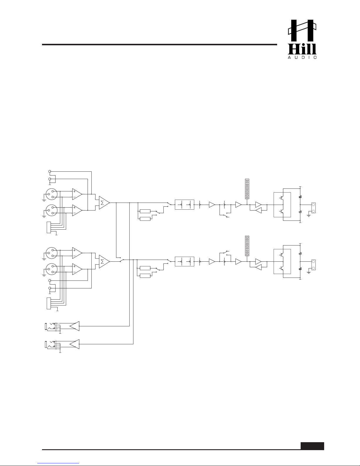
Block Diagram
Preamplifier Section
Signal/Noise.............................................>82dB (Line)
Crosstalk Damping....................................>65dB (Line)
THD......................................................<0.05% (Line)
Frequency response.................................20Hz – 20 kHz
Power Amplifier Section
Power, both channels driven @ 4 Ohms.........2x80W RMS
Power, both channels driven @ 8 Ohms.........2x50W RMS
Damping factor.....................................................>300
General Data
AC IN (EU version)..........................AC220-250V~ 50Hz
AC IN (US version)..........................AC110-120V~ 60Hz
Power consumption......................................max. 200W
Dimensions....................W483(447)xH44.5xD194.0mm
(parentheses = without rack ears)
Weight................................................................4.4kg
Maintenance and warranty
While we have chosen the best components to make this product as rugged and reliable as possible, some parts in audio
products (potentiometers, faders, switches) are subject to wear which is a matter of operation cycles, and not of time.
While providing a full time-based warranty according to the country’s of purchase requirements on the function of the
electronic circuitry, we hence have to limit the warranty on such electro-mechanical parts to 90 days from the date of
purchase.
In many cases, malfunction of electro-mechanical parts occurs due to dust contamination, which may require cleaning of
such parts. As the inside of such parts is not accessible, a common practice is to use cleaning fluids in the shape of
sprays. Please be reminded that many of such fluids contain chemicals which may wash away the dust but at the same
time corrode or damage contact surface and may cause cosmetic damage to other parts. We hence explicitly exclude
any claims for exchange of damaged part due to mechanical or chemical impact.
L
A
R
1
2
3
1
2
3
T
R
T
R
L
B
R
1
2
3
1
2
3
2Band EQ
100Hz HPF
40Hz HPF
100Hz HPF
40Hz HPF
HPF SEL
HPF SEL
HPF
BYPASS
HPF
BYPASS
Parallel/Stereo
2Band EQ
1
2
3
4
5 +
+
-
1
2
3
4
5 +
+
-
Rear MAX Level
Rear MAX Level
Front MAX Level
Front MAX Level
Front Volume Bypass
Front Volume Bypass
Limiter
Limiter
PRE OUT
+VCCB
-VCCB
+VCCA
-VCCA
+
-
+
-
Meter-A
Meter-B
OUTPUT A
OUTPUT B
Page 10

PAGE 9
USER MANUAL - IPA200 INSTALLATION AMPLIFIER
Page 11

PAGE 10
USER MANUAL - IPA200 INSTALLATION AMPLIFIER
Page 12
www.hill-audio.com
Hill Audio products are developed, manufactured and distributed by
Adelto Technologies
Vanguard Way, Shoeburyness, Essex SS3 9QY, UK
www.adelto.com | [email protected]
EC Declaration of Conformity
Manufacturer: Adelto Technologies Limited
Address: Vanguard Way, Shoeburyness, Essex SS3 9QY, UK
We declare on our own responsibility, that the equipment
Hill Audio IPA200
Hill Audio IPA400
Hill Audio IMA200
Hill Audio IMA400
is in conformity with the following directives and standards or regulations:
EMC Directive 2004/108/EC
EN55103-1:2009 (Emissions)
EN55103-2:2009 (Immunity)
EN61000-3-2:2006 + A1:2009 + A2:2009
EN61000-3-3:2008
LVD Directive 2006/95/EC
EN60065:2002 A1:2006 + A11:2008 + A2:2010
ROHS Directive 2002/95/EC
and is marked as follows:
Shoeburyness, 24. January 2014
Authorized SignaturePlace and date of issuing
 Loading...