

Page 1
Wireless Reverse Parking System
with 4 Parking Sensors
PDC340
Page 2
COMPONENTS
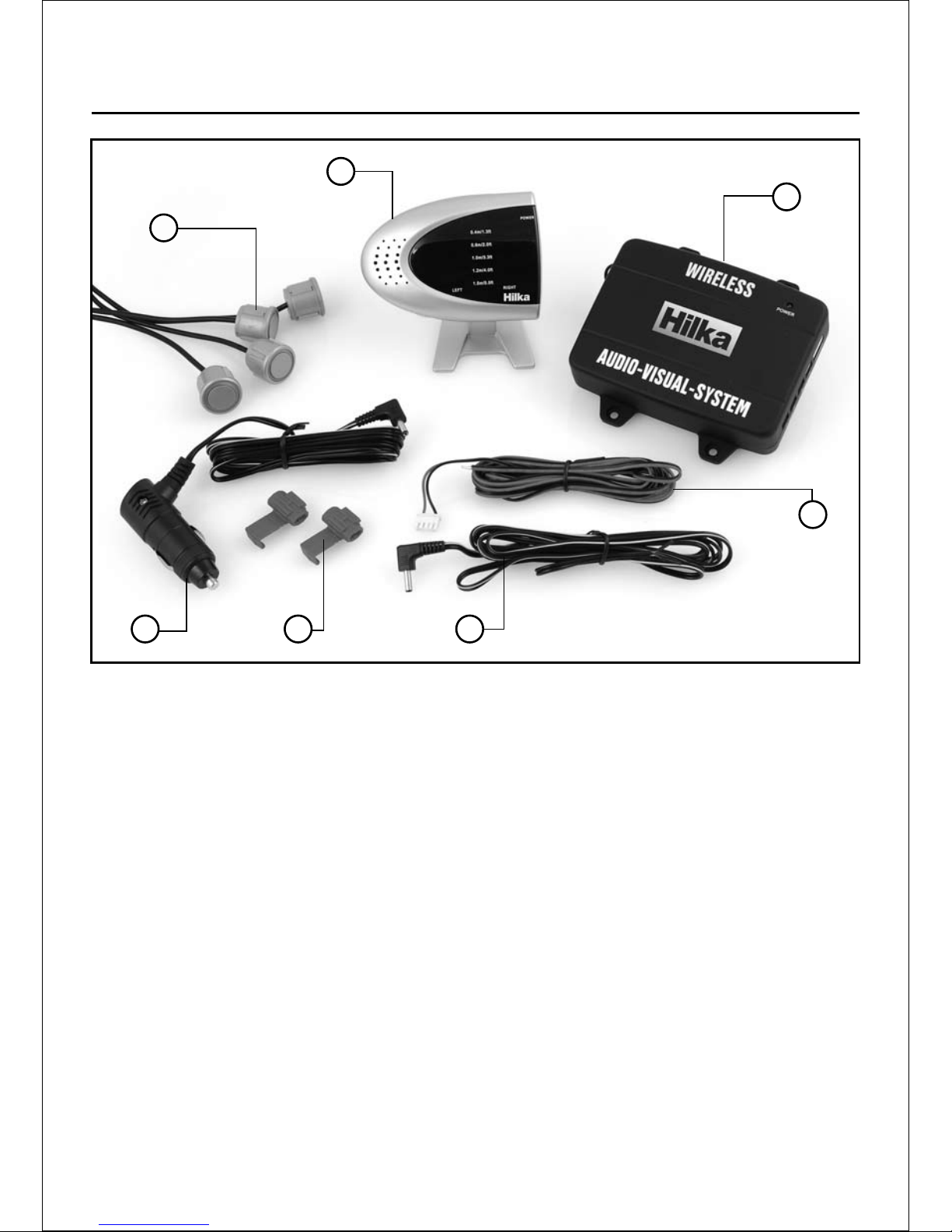
Component List
Control Unit (Transmitter)1.
Receiver Unit2.
Sensors3.
12V power cable for use with 4.
receiver unit
12V power cable for use with 5.
control unit (hard-wiring)
12V power cable for use with 6.
receiver unit (hard-wiring)
Snap-on Connections7.
-1-
1
3
6
2
5
4 7
Page 3
-2-
INTRODUCTION
Thankyou for purchasing the PDC340
Reverse Parking Sensor. This manual
details the installation and operation of
your product. Please read it carefully and
keep to hand for future reference. Ensure
that the product is working correctly before
attempting permanent installation.
The PDC340 is an automatic reversing alert
system. It gives a safety warning which tells
the driver the distance between the rear of
the vehicle and any object in its path.
The sensors transmit an ultrasonic signal
when the car is reversing. When the signal
senses an object, it will be reected and
received by the PDC340 control unit. These
reected signals are analysed by the control
unit microprocessor to detect whether the
obstacle is in your path and at what distance.
The receiver unit illustrates the distances
involved with a series of beeps and
illuminated LED’s letting the driver know how
far away the closest object is located.
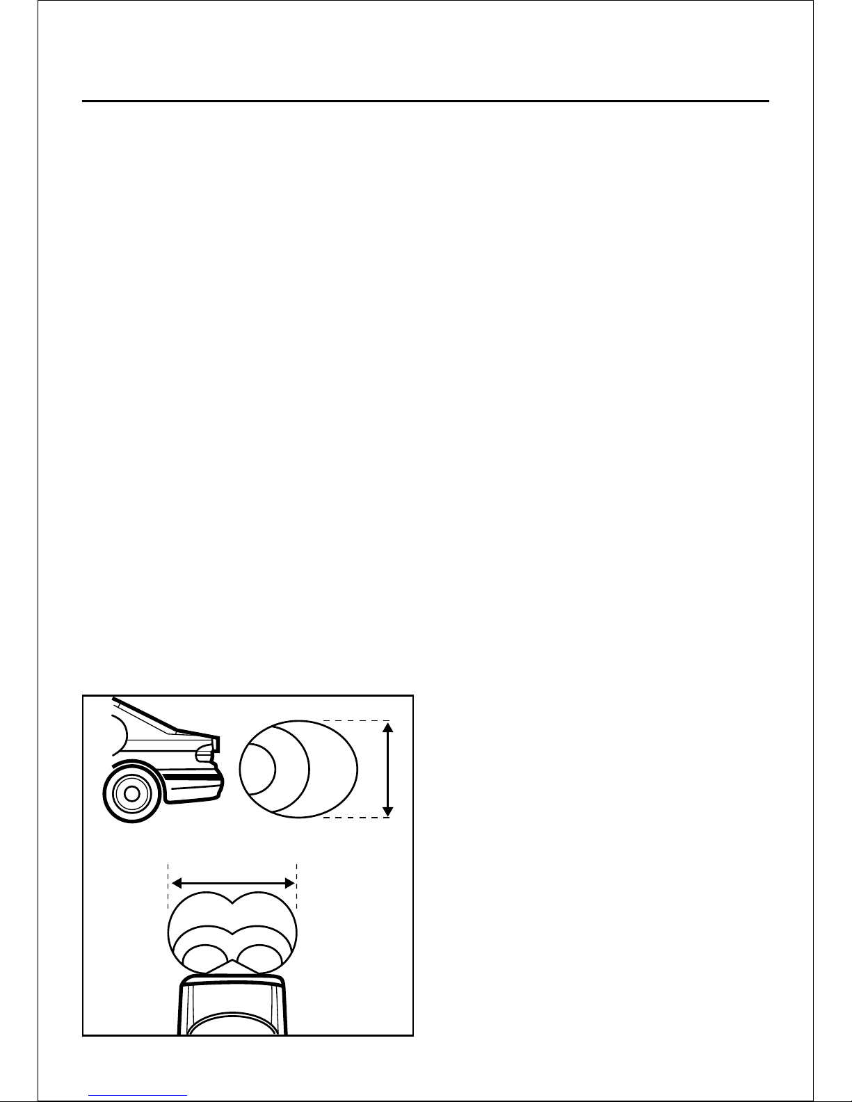
Below are graphical representations of the
PDC340 detecting patterns:
FEATURES
The ideal assistant for reverse parking.•
Detects objects (or people etc.) from •
approximately 40cm up to 1.5 meters
behind the vehicle.
Lessens the risk of damage from unseen •
objects when parking.
Illustrates distance between vehicle and •
object by clear sound and red, yellow or
green LED indicators. Adjustable volume.
2 reverse sensors for optimal detection.•
Automatic system activation your vehicle is •
put in reverse gear.
Quick assembly with 2-wire installation and •
3 connectors.
Parts with this system include:
1 x Control Unit (transmitter) 1 x Receiver
unit
4 x Ultrasonic sensors
1 x 12V power cable (hard-wiring) for use
with the control unit
1 x 12V power cable (hard-wiring) for use
with the receiver unit
1 x 12V power cable (cigarette lighter
socket) for use with the receiver unit
4 x screws 2 x Snap-on Connectors
Adhesive mounting pads
GENERAL NOTES: READ BEFORE USE!
Only to be used as a reversing aid•
Do Not t to the front of your vehicle•
Not suitable for vehicles with rear engines•
Do not use with a vehicle that has a •
reversing horn or alarm
Do not extend cables (may distort the •
sensors)
Do not paint or spray the sensors•
Install with car in horizontal position.•
A false response may be recorded if a DC •
to AC power converter is being used close
by.
80cm
190cm
Page 4
Installation
-3-
INSTALLATION GUIDE
IMPORTANT! During the installation
your vehicle must be in neutral and the
ignition switched OFF. Disconnect the
battery following the vehicle manufacturers
instructions before commencing.
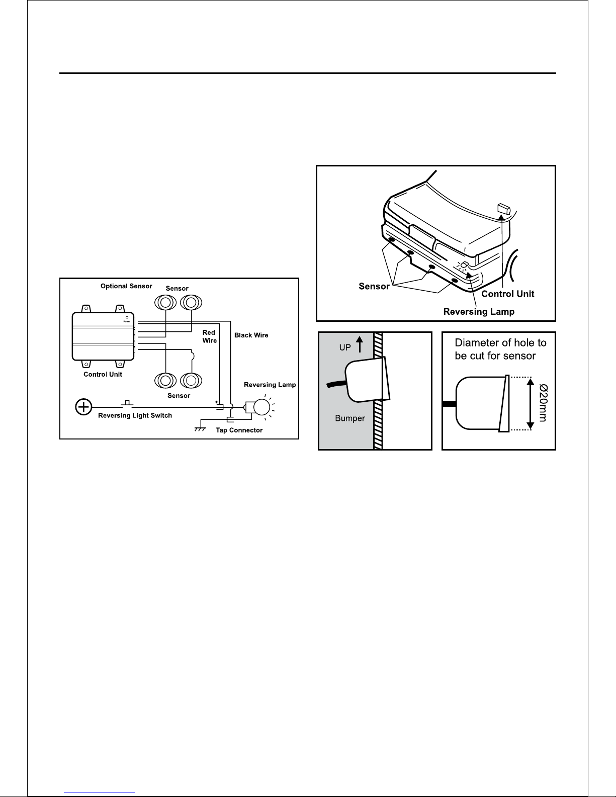
Wiring diagram:
Below is a wiring diagram for the PDC340
sensors and control unit showing the
necessary connections. Please follow all the
instructions before installing your reversing
sensors.
LOCATION OF THE SENSORS
IMPORTANT NOTE: • It is strongly
recommended that the sensors are fully
tested in the proposed positions prior
to drilling or performing any irreversible
alterations to your vehicle. Before
installation rst determine the nal position
for the sensors.
Locate a at area at the rear of the vehicle. •
Sensors should be tted between 55cm70cm from the ground. If tted higher
than 70cm the sensors may not detect
low objects. If lower than 55cm the signal
may reect from the ground and produce a
false reading.
The sensors should be tted 90cm apart •
from each other (at the same height).
The sensors are intended to be installed at •
a slight angle (see Fig.4).
Drill holes of 20mm in diameter to •
accommodate the sensors (see Fig.5). If
you are in any doubt as to where you can
drill safely, seek advice from your vehicle
manufacturer.
WIRING THE SENSORS
Having chosen a location for the sensors, •
you must decide on a route for running the
wiring through your vehicle’s interior. Do
not allow any wires to hang dangerously.
LOCATION OF THE CONTROL UNIT
Locate the transmitter towards the rear of •
the vehicle (e.g. in boot), within reach of
the sensor and power wires.
Only once a suitable position is established •
and the system has been fully tested can
the control unit be permanently installed
using the screws provided.
Fig.2
Fig.3
Fig.4
Fig.5
Page 5
-4-
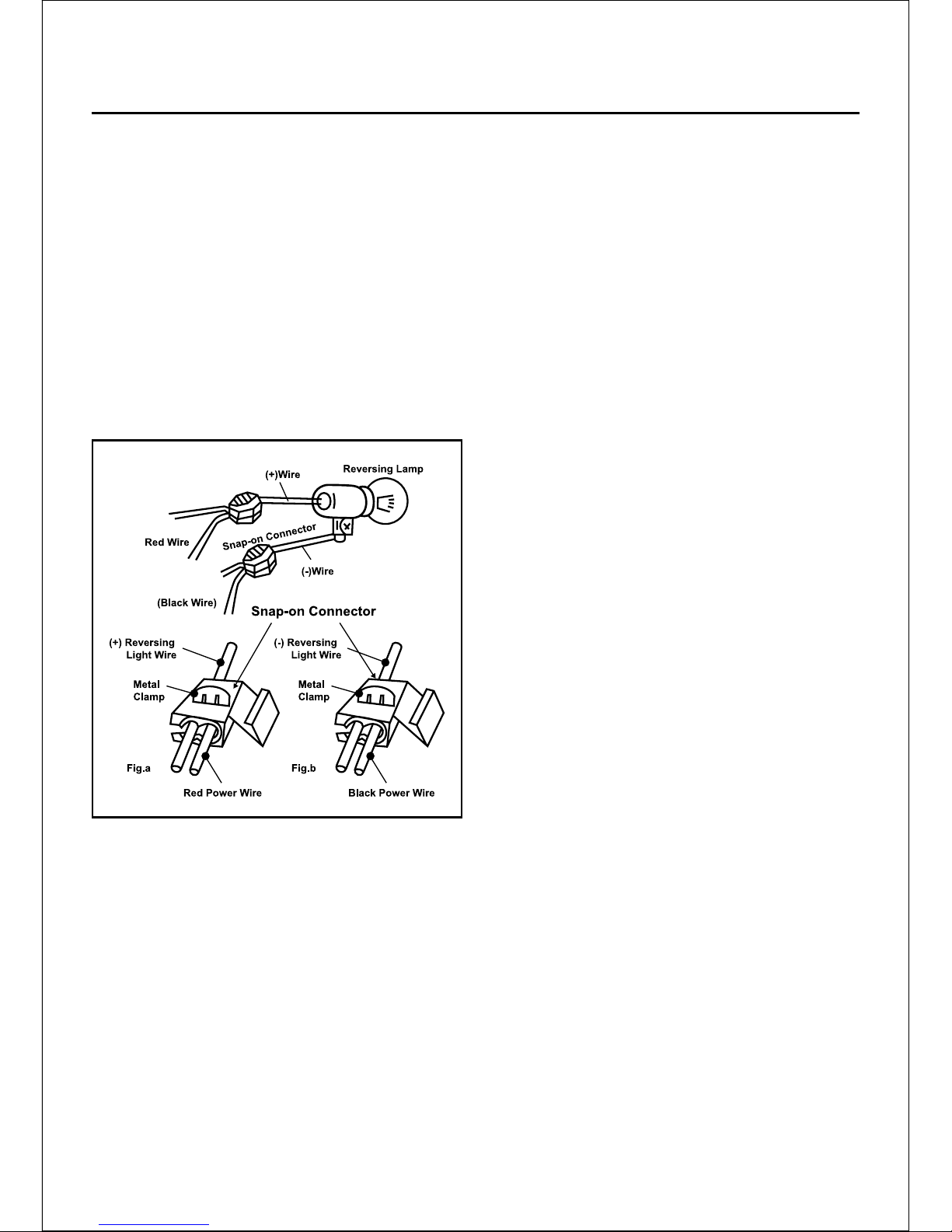
CONNECTING THE WIRING TO THE
CONTROL UNIT (TRANSMITTER)
You need to connect the red and black •
transmitter power cables to your vehicles
reversing light wires.
The red power cable should be connected •
to the positive reversing light wire (this
is the wire that becomes live when you
select the reverse gear), using the snap-on
connector provided.
Connect the black power cable to the •
ground wire from the reversing light, again
using the snap-on connector provided.
LOCATING THE RECEIVER UNIT
This must be installed inside the vehicle •
(e.g. on the dashboard) where you can see
and hear it easily whilst manoeuvring.
Do not attach in a position that could •
interfere with the normal driving of the
vehicle.
Attach using the sticky pad supplied.•
This must be installed within reach of the •
chosen power supply.
CONNECTING THE POWER TO THE
RECEIVER UNIT
Connect the receiver unit to the power •
supply either by plugging in the cigarette
socket adapter or by hardwiring (seek
advice from your vehicles manufacturer).
You will need to reconnect the battery
following manufacturers instructions.
SYSTEM SETUP
Once you have installed the system and •
switched it on, you will need to press the
‘LEARN’ button. This is located on the
back of the receiver. This lets the receiver
unit sense the transmitter unit and set up a
frequency.
If the mutual frequency is found •
successfully, then the receiver unit will
beep twice.
If the frequency is not found then you will •
hear a long beep. If this happens, switch
the receiver unit off and on, then press
the ‘LEARN’ button again. If you still have
problems, check the system setup and that
all wires are connected properly, and that
the transmitter unit is switched on.
Fig.6
Page 6
OPERATION
When you select reverse gear, you will hear
a beep. This indicates that the PDC340 is
working and has been activated (it does not
necessarily mean that there is something
behind you.)
As you begin to reverse and an object
comes within range, you will hear a beeping
sound from the main unit. The frequency
or pitch depends on the range of the object
being detected. If necessary, you can use
the switch on the side of the unit to increase
or decrease the volume.
The detective range is 0.4m to 1.5m. Its
resolution is 30mm. The accurate distance is
transmitted from the control unit (transmitter).
The LED display corresponds to the shortest
distance from the obstacle.
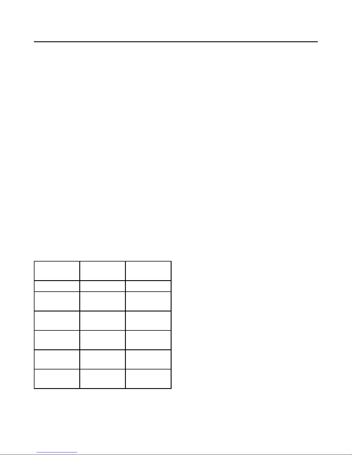
The table below shows the alarm speed
corresponding to the range of the object
detected.
WHEN THE BEEPING INCREASES
AND FINALLY BECOMES A
CONTINUOUS TONE AND ALL OF
THE LED’S ON THE MAIN UNIT ARE
FLASHING, YOU SHOULD STOP
IMMEDIATELY, EVEN IF THERE IS NO
OBVIOUS OBSTACLE BEHIND YOU.
Your PDC340 may work slightly differently to
what is shown in the table above depending
on circumstance and also on how your
sensors are positioned. You should practice
using your set up in a known area before
using it in earnest on a day to day basis.
With use, you will nd it a convenient and
useful aid to your reverse parking.
-5-
DISTANCE AUDIO
ALERT
VISUAL
ALERT
over 1.5m No Beep No Display
1.5m-1.2m (•) (Beep) Green LED
Lit
1.2m-1.0m (•)(•) Beep
Beep
Green LED
Lit
1.0m-0.6m (•)(•)(•) Yellow LED
Lit
0.6m-0.4m (•)(•)(•)(•) Yellow LED
Lit
below 0.4m continuous
tone
All LED are
Lit
Page 7

Fault Finding
FAULT DESCRIPTION POSSIBLE CAUSE/REMEDY
False or no response Steep slopes or thin bars. Bushes or other
foliage could absorb the signals. Electricity
wires nearby could interfere with the signal.
(See diagram below) Sensors covered with
snow, mud or ice etc.
Power light does not come on when reverse
gear has been chosen.
Check that the power wires are properly
connected to the reversing light power
wires. Check that the snap-on connectors
are providing a good contact.
Sensor always shows an object is FT (Red
LED) behind vehicle.
Check whether the sensors are located too
low, or the angle is pointing downwards and
therefore detecting the ground.
Power light (Green LED) is on, but the unit it
not detecting any obstacles
Check whether the sensors cable is
correctly plugged into the 2 pin socket of the
transmitter unit.
Unit does not show correct distances. Check that the sensors are properly
mounted. Adjust as necessary.
-6-
Page 8

PDC340 - Issue1 - R.W. 14-07-08
HILKA TOOLS
1 ROEBUCK PLACE, ROEBUCK ROAD, CHESSINGTON, SURREY KT9 1EU
If faults cannot be remedied, contact the Helpline on 020 8391 6767
www.hilka.co.uk
 Loading...