


HF / VHF Transceiver
PT-8000A
Operating Manual
Version 2.01.10

Copyright-notice to the ring binder title
All Figure rights reserved by: Bundeswehr / PIZ Marine, DGzRS and Hilberling GmbH

i
HF / VHF Transceiver
Hilberling PT-8000A
Operating Manual
PT-8000A, HN-8000 and T9
are
developed and manufactured in the EU
by
Hilberling GmbH
Heinrich-Hertz-Strasse 2
24790 Schacht-Audorf
Germany
Logo and name of Hilberling GmbH are registered trademarks
Distribution of the complete Document is desired
However, each partial copy or distribution is prohibited
Errors and changes excepted

ii
IMPORTANT NOTE AND PRECAUTIONS
Important
Read and save this Operating Manual carefully before attempting to operate the HF/VHF PT-8000A transceiver. This
manual contains important safety and operating instructions for the transceiver.
Precautions
WARNING HIGH VOLTAGE !
Never touch an antenna or internal antenna connector during transmission. This may result in an electrical
shock or burn of your skin by high-frequency.
WARNING !
Never apply AC to the DC socket on the transceiver rear panel. This will ruin the transceiver and may cause
fire.
CAUTION !
Never allow any object touch any internal parts or connectors on the rear panel of the transceiver. This
could cause electrical shock and severe injury.
PROTECT the transceiver from precipitation like rain or any liquid. Do not operate the transceiver in
excessively dusty or very humid environment.
PROTECT the transceiver from operation by any unauthorized person notably children.
AVOID placing and using the transceiver in areas with temperatures below -15°C or above +50°C. If
the environment temperature drops so low that the dew point is undercut, avoid operating before the
devices are dried completely.
AVOID placing the transceiver and the power supply against a wall. This may inhibit proper air circulation
and could cause overheat. Do not cover any air inlets and outlets at top, bottom and rear panel of the
devices.
USE CARE when connecting the transceiver to a linear amplifier. Keep in mind the performance limits or operating
ranges of electrical connectors and interfaces. Set the PT-8000A RF-output level to less than the linear amplifier’s
maximum input level to prevent amplifier damage.
USE CARE when not operating the transceiver with Hilberling T9 microphone. Others may have different pin
assignments and connecting to the transceiver may cause damage to the transceiver and the microphone.
Copyright © 2008-2020 by Hilberling GmbH

PT-8000A Operating Manual v2.01.10 iii
TABLE OF CONTENT
Important Note And Precautions ii
Table of Contents iii
Federal Communications Commission (FCC) Statement vi
3 Introductory Notes
3.1 Scope of Delivery ............................................................................................................................ 1
3.2 About this Manual ........................................................................................................................... 1
3.3 Notes on Placing ............................................................................................................................. 2
3.4 Antenna Considerations / Antenna Tuner ........................................................................................... 3
4 Connectors PT-8000A
4.1 Connectors at Rear Panel ................................................................................................................. 4
4.1.1 HF/VHF Connectors J1 - J11 ............................................................................................................. 4
4.1.2 Connection Sockets J12 - J22 and Operating Elements ........................................................................ 5
4.1.3 Wiring J15 - J21 .............................................................................................................................. 6
4.2 Connectors at Front Panel ................................................................................................................ 7
4.2.1 Connection Sockets 1 - 3 ................................................................................................................. 7
4.2.2 Wiring ............................................................................................................................................ 7
5 Power Supply HN-8000
5.1 General Description ......................................................................................................................... 8
5.2 Connectors at Rear Panel / Connection Sockets J1 up to J4 ................................................................. 8
5.3 Operating and Display Elements at Front Panel .................................................................................. 9
6 Accessories
6.1 Microphone Hilberling T9 ................................................................................................................. 9
6.2 Wiring / Cables ............................................................................................................................... 9
6.3 Operating Manual and Software/Documentation CD ......................................................................... 10
7 Installation / Initial Operation
7.1 Introduction .................................................................................................................................. 11
7.2 Cable Connections ......................................................................................................................... 11
7.3 Initial Settings ............................................................................................................................... 11
8 Operating and Display Elements
8.1 Main Operating and Display Elements .............................................................................................. 12
8.2 TFT-Display .................................................................................................................................. 13
8.3 Clustered Front Panel Controls ........................................................................................................ 15
8.4 Controls with Integrated Push-Button Function and Controls for Adjustments ..................................... 16
8.5 Side Panel Controls (Level Adjustments) .......................................................................................... 17
8.5.1 Input Level – Left Hand Side .......................................................................................................... 17
8.5.2 Output Level – Right Hand Side ...................................................................................................... 17
8.6 Pushbuttons With LED Status Display .............................................................................................. 18
8.7 LED Status Display ........................................................................................................................ 19
9 MAIN- and SUB-RX Operations 20
10 Modes of Operation MODE 22
10.1 Single Side Band and Continuous Wave SSB / CW .......................................................................... 22
10.1.1 SSB Single Side Band ................................................................................................................... 22
10.1.2 CW Continuous Wave .................................................................................................................. 23
10.2 AM / FM Amplitude Modulation / Frequency Modulation .................................................................. 24
10.2.1 Repeater Mode – How to Set the Repeater Frequency Shift ............................................................... 25
10.2.2 Repeater Mode – TX Frequency Display ........................................................................................... 25
10.3 DATA Transmission (Digital Operation Modes) / RTTY ...................................................................... 26
11 Selecting Frequencies 27
11.1 Select with BAND Keys ................................................................................................................... 27
11.1.1 HF Amateur Radio Bands ............................................................................................................... 27

iv
11.1.2 VHF Amateur Radio Bands .............................................................................................................. 28
11.1.3 Transverter Operation .................................................................................................................... 30
11.2 Numerical Frequency Input ENTER ................................................................................................ 32
11.3 Channel Operation
11.3.1 Recall of Stored Frequencies CHANNEL .......................................................................................... 34
11.3.2 Storage of Frequencies MEM ........................................................................................................ 36
11.4 VFO Main Tuning Knob (
11.5 STEP VFO Control .......................................................................................................................... 39
11.6 VFO Management ......................................................................................................................... 40
11.7 SPLIT Operation ............................................................................................................................ 42
11.8 RIT / XIT Operation ....................................................................................................................... 43
11.9 Locking VFO Settings LOCK .......................................................................................................... 44
12 Filter Bandwidth and Shift Function FILTER WIDTH / SHIFT 45
12.1 Filter Bandwidth DSP Off ................................................................................................................. 46
12.2 Filter Bandwidth DSP On ................................................................................................................. 46
13 Notch Filter / Noise Reduction / Noise Blanker NOTCH / NR / NB
13.1 Notch Filter: IF-Notch and DSP Multi Notch .................................................................................... 47
13.1.1 IF NOTCH Filter ............................................................................................................................. 47
13.1.2 DSP Multi NOTCH Filter („digital“ MNF) ............................................................................................ 47
13.2 DSP Noise Reduction NR .............................................................................................................. 48
13.3 Noise Blanker NB ......................................................................................................................... 48
active
RX) and SUB VFO Tuning Knob (RX
in the Background
) ....................... 38
14 Squelch SQL 49
15 RX Gain Control AGC / RF-GAIN
15.1 Automatc Gain Control AGC .......................................................................................................... 50
15.2 Manual Gain Control RF-GAIN ....................................................................................................... 51
16 Storage Frequency Scanning SCAN
17 Firmware Versions / Calibration /
Speakers / Display / Voice Recorder MENU I 53
Baud Rate CAT Interfaces MENU II 54
17.1 RX–Speaker Allocation Audio NORM / SPLIT .................................................................................. 54
17.2 Calibration of Internal Reference REFERENCE CALIBRATION ........................................................... 55
17.3 Brightness of Display DIM ............................................................................................................ 56
17.4 NF Recording VOICE RECORDER ................................................................................................... 57
18 Scale Select METER 58
19 Basic Settings RX/TX 58
19.1 RX Settings ................................................................................................................................... 59
19.1.1 HF: Antenna Select / Preamplifier / Preselector / Attenuator / IF-2 Filters ........................................... 59
19.1.2 HF: Attenuator / IF-2 Filter Select ................................................................................................... 60
19.1.3 VHF: Preamplifier PRE AMP / DC on Antenna OUT DC AMP ............................................................ 61
19.1.4 VHF: IF-2 Filter Select .................................................................................................................... 62
19.2 TX Settings ................................................................................................................................... 63
19.2.1 Leveler TX Audio LEV ................................................................................................................... 63
19.2.2 Equalizer Operation TX-Audio EQ .................................................................................................. 64
19.2.3 Keyer Select .................................................................................................................................. 65
19.2.4 TX Filter Select / TX Shift Select ...................................................................................................... 66
19.2.5 TX Signal Settings ......................................................................................................................... 67
temporarily disabled
52
20 Transmitter Controls 68
20.1 Antenna Tuner .............................................................................................................................. 68
20.1.1 Activate TUNER ........................................................................................................................... 68
20.1.2 Start Re-Tuning Cycle START......................................................................................................... 68
20.1.3 Permanent Transmit Operation TX / ON ........................................................................................ 68
20.2 ZERO-BEAT ................................................................................................................................... 69
20.3 Microphone Sensitivity MIC (Gain) ................................................................................................. 69
20.4 Compression TX Audio PROC ........................................................................................................ 69

PT-8000A Operating Manual v2.01.10 v
20.5 Transmit Power Control TX-PWR ................................................................................................... 70
20.6 VOX Operation .............................................................................................................................. 70
20.6.1 VOX Threshold .............................................................................................................................. 70
20.6.2 VOX ANTI-TRIP Activating Suppression ......................................................................................... 71
20.6.3 VOX DELAY Hold Time ................................................................................................................. 71
20.7 Monitoring TX Signal MONITOR .................................................................................................... 71
20.8 Fall Time TX on CW TX-DELAY ..................................................................................................... 71
20.9 Keying Speed CW KEY SPEED ....................................................................................................... 71
Appendix
A1 IF Monitor Software (Windows® Program)
A1.1 Introduction ............................................................................................................................... A1- 1
A1.2 Hardware Requirements .............................................................................................................. A1- 1
A1.3 Setup Software ........................................................................................................................... A1- 1
A1.4 Installation of the IF Monitor Program .......................................................................................... A1- 1
A1.5 Connect PT-8000A to PC by Audio Cable ...................................................................................... A1- 2
A1.6 Start and set up the Program ...................................................................................................... A1- 2
A1.6.1 Program Window ........................................................................................................................ A1- 3
A1.6.2 Automarker and Marker .............................................................................................................. A1- 3
A1.6.3 Peak Hold .................................................................................................................................. A1- 4
A1.6.4 Sample Rate and Buffer Setup ..................................................................................................... A1- 4
A1.6.5 Signal Level Adjustment .............................................................................................................. A1- 5
A1.6.6 Signal Level and Panorama Width Scaling ..................................................................................... A1- 8
A1.6.7 Waterfall Chart ........................................................................................................................... A1- 9
A2 Firmware Update and Update Software (Windows® Program)
A2.1 Preliminary Note ......................................................................................................................... A2- 1
A2.2 Introduction ............................................................................................................................... A2- 1
A2.3 Requirements and Procedure ....................................................................................................... A2- 1
A2.4 Setup Software and Firmware ...................................................................................................... A2- 2
A2.5 Install Update Program on PC ...................................................................................................... A2- 2
A2.6 Connect PT-8000A to PC by USB Data Cable ................................................................................. A2- 2
A2.7 Start and set up the Update Program ........................................................................................... A2- 3
A2.7.1 Manual COM Port Setting ............................................................................................................ A2- 3
A2.7.2 Select Firmware ......................................................................................................................... A2- 4
A2.8 Get PT-8000A ready to update .................................................................................................... A2- 5
A2.9 Update of MAIN-CPU .................................................................................................................. A2- 7
A2.10 Update of RX- and ANT-Tuner-CPU ............................................................................................ A2- 10
A3 Technical Documents
A3.1 Technical Data ........................................................................................................................... A3- 1
A4 Customer Information
A4.1 User Information ........................................................................................................................ A4- 1
A4.1.1 Declaration of Conformatiy (shortened version) ............................................................................. A4- 1
A4.1.2 Note Amateur Radio Operation .................................................................................................... A4- 1
A4.2 Warranty Terms ......................................................................................................................... A4- 1
A4.3 Disposal Rules ............................................................................................................................ A4- 2
A5 Lists
A5.1 Index ........................................................................................................................................ A5- 1
A5.2 List of Figures ............................................................................................................................ A5- 3
A5.3 List of Tables ............................................................................................................................. A5- 6
A5.4 Glossary .................................................................................................................................... A5- 7

vi
FEDERAL COMMUNICATONS COMMISSION (FCC) STATEMENT
The Hilberling PT-8000A was tested and found to be in compliance with 47 CFR, Part 15 of the FCC Rules, as an
unintentional radiator and as a generic receiver. These limits are designed to provide reasonable protection against
harmful interference in a residential installation.
FCC ID: V84PT8000
This device complies with Part 15 of the FCC rules. Operation is subject to the following two
conditions:
(1) this device may not cause harmful interference, and
(2) this device must accept any interference received, including interference that may cause
undesired operation.
CAUTION: Changes or modifications to the PT-8000A not expressly approved by Hilberling GmbH could void your
authority to operate this transceiver under FCC regulations

PT-8000A Operating Manual v2.01.10 1
Quantity
Description
Fig.
1
Power Supply HN-8000
6
1
Microphone T9
7
1
AC Line Voltage Cable (Power Grid ⬄ HN-8000)
8
1
DC Power Cable (HN-8000 ⬄ PT-8000A)
9
1
Ground Cable (HN-8000 ⬄ PT-8000A)
10
1
Speaker Cable (HN-8000 ⬄ PT-8000A)
11
1
Data Cable (PC/Notebook ⬄ PT-8000A)
12
1
Phono Plug 6,3mm
1
DB-25 Male Plug (D-Sub 25pol)
1
DA-15 Male Plug (D-Sub 15pol)
1
DE-9 Male Plug (D-Sub 9pol)
1
Operating Manual
13a
1
Software CD-ROM
• PT-8000A IF Monitor Program (Windows®)
• PT-8000A Update Program (Windows®)
• Operating Manual (PDF)
13b
Tab. 1
3 INTRODUCTORY NOTES
3.1 Scope of Delivery
Examine your PT-8000A for signs of damage during shipping. Should any damage be apparent please take
appropriate measures (contacting your carrier). We recommend to retain all packing material – it might be used for
shipment of the radio.
Listed below are the hardware and all accessories delivered with your PT-8000A. Make sure you have received and
unpacked everything:
3.2 About this Manual
The PT-8000A represents primarily state of the art analog RF-design. However digital signal processing and
microprocessor controlled circuits add to this transceiver in a synergistic way. Hence, features and functions can be
easily improved and/or tailored to customer needs through updating the Hilberling GmbH firmware using the USB
interface (please have a look at Appendix A2).

2
In this manual the following signs and symbols are used:
The STOP sign indicates a warning that must be obeyed for safety reasons.
This sign indicates an important explanation or a specific advice which should be obeyed.
An additional information or explanation is indicated this way.
3.3 Notes on Placing
When selecting the place for operating the PT-8000A bear in mind the general limitation concerning
environmental conditions as outlined in the specifications and the cautions at the very beginning of
this manual (P. ii).
Always handle the PT-8000A with care – consider the weight of more than 50 lbs, please!
Please make sure proper air circulation. Do not cover any air inlets and outlets at top, bottom and
rear panel of the devices.
Choose the place of installation so that all connectors of the PT-8000A are reachable any time.
Select a power outlet that is capable to handle the power requirements. Connect your PT-8000A to
a proper ground system – which is important for optimum operation of any HF transceiver –
especially when operating high power by using an external amplifier. In the past, a ground
connection to a copper water pipe was often used for this purpose. Recent revisions to the National
Electric Code has made this practice a code violation. Bear in mind that modern supply water
installations utilize plastic pipe – which do not function grounding purposes. Never use a gas or
electric pipe since the connection could cause an explosion or electric shock. A good grounding
system not only prevents electrical shock but also helps to ensure trouble free operation and will
diminish television and broadcast interference (TVI/BCI).
For your convenience you might raise the front of PT-8000A and HN-8000 by unfolding and locking tilt bails
mounted at the front equipment feet into front position as shown on Fig. 1 (see next page).

PT-8000A Operating Manual v2.01.10 3
Fig. 1
If a large resistance will complicate the unfolding, please spread the bail easy for hurdle the locking
nib to avoid damage of the equipment foot.
3.4 Antenna Considerations / Antenna Tuner
Standing wave ratio (SWR) may increase significantly
when using an antenna outside of the specific
frequency range for which it is tuned. The final power
amplifier will operate at peak performance only when
its load is resistive – i.e. the SWR is close to 1.0.
Therefore the PT-8000A is equipped with an
automatic antenna tuner (ATU) which does not
actually tune the antenna. The ATU instead matches
the feed line to the final amplifiers so they always
“see” a SWR close to 1.0. The ATU has its limits –
tuning mismatches with SWR greater than 2.0 become
difficult and will exceed the capabilities of the ATU.
Using a tuned or resonant antenna with 50 Ohm
impedance at the feed point for the specific
frequencies is highly recommended. The purpose of
the ATU is to ensure that a resonant antenna can be
used at the limits of the band selected with optimum
performance of both PT-8000A and antenna system.
Never try to hook up a symmetrical open feeder line
(balanced, twin-lead, ladder line etc.) directly to the
PT-8000A. Instead use 50 ohm coaxial feeders only.
The connectors supplied on the PT-8000A are all Type
N.
With the ATU it is acceptable to use a broadband
antenna system like a log periodic or T2FD system
which trade wide bandwidth for an SWR ranging as
high as 2.0.

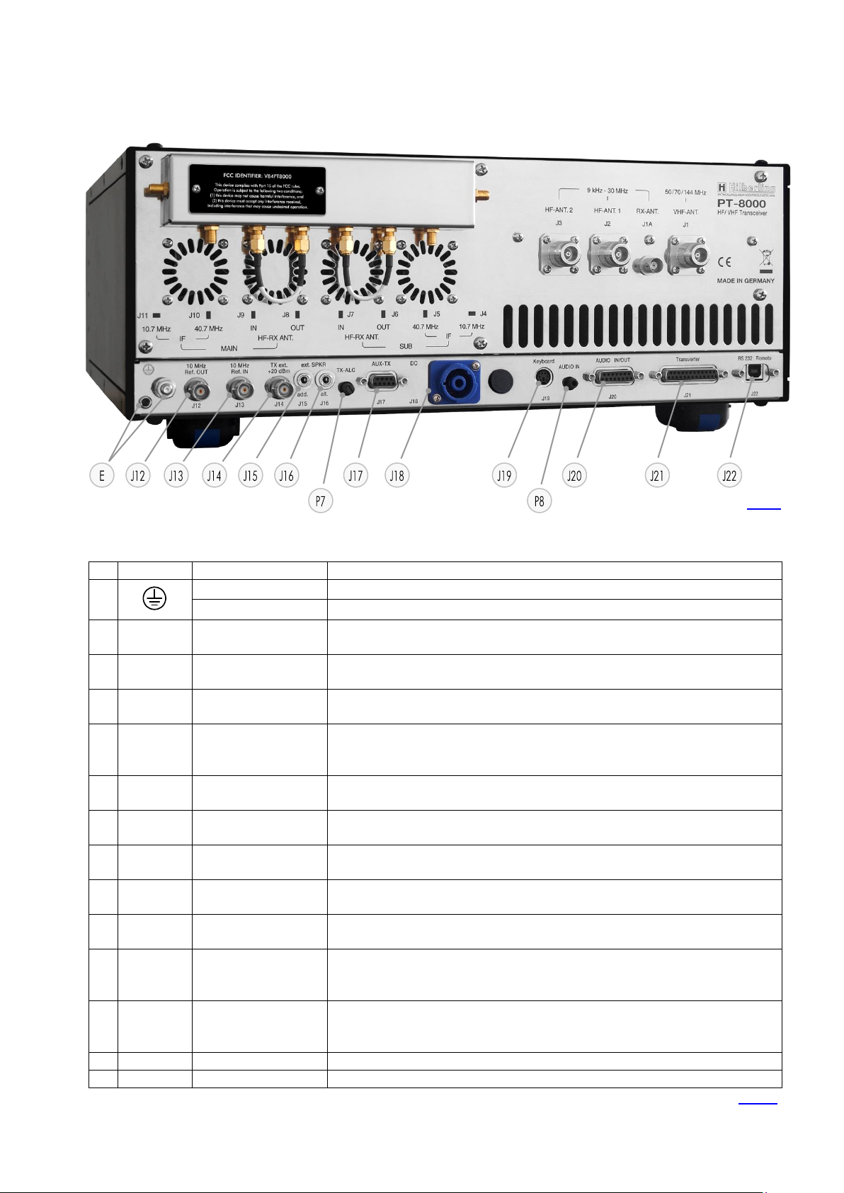
4
No.
Label
Type
Description
J1
VHF-ANT
50/70/144 MHz
N
Input / Output VHF Antenna Range 110 ... 143,990 MHz (RX only)
50 / 70 / 144 MHz Band (RX and TX)
J1A
RX-ANT
9 kHz ... 30 MHz
BNC
Input VLF/LF/MF/HF Antenna Range 9 kHz … 30 MHz (RX only)
For DUPLEX mode the input may stay open during transmission.
J2
HF-ANT 1
9 kHz ... 30 MHz
N
Input / Output VLF/LF/MF/HF Antenna Range 9 kHz ... 30 MHz (RX and TX)
J3
HF-ANT 2
9 kHz ... 30 MHz
N
Input / Output VLF/LF/MF/HF Antenna Range 9 kHz ... 30 MHz (RX and TX)
J4 IF 10,7 MHz
SUB
SMA
Output 2nd IF 10.7 MHz of SUB-RX. The output is tapped after the 2nd mixer. No AGC and no 10.7MHz
Xtal filter at that point. Thus bandwidths are determined by prefilters
J5
IF 40,7 MHz
SUB
SMA
Output 1st IF 40.7 MHz of SUB-RX. The output is tapped after the 1st mixer – thus being broadband when
preselector is disengaged
J6
HF-RX ANT SUB
OUT
SMA
HF Antenna Signal for SUB-RX after passing internal antenna switch respectively TX/RX relay. Connected to
J7 (by default) or to input of external equipment (QRM-eliminator, ANT-switch panel etc.)
J7
HF-RX ANT SUB
IN
SMA
HF signal input for SUB-RX. Connected to J6 (by default) or to output of external equipment (QRMeliminator, ANT-switch panel etc.)
J8
HF-RX ANT MAIN
OUT
SMA
HF Antenna Signal for MAIN-RX after passing internal antenna switch respectively TX/RX relay. Connected to
J9 (by default) or to input of external equipment (QRM-eliminator, ANT-switch panel etc.)
J9
HF-RX ANT MAIN
IN
SMA
HF signal input for MAIN-RX. Connected to J8 (by default) or to output of external equipment (QRMeliminator, ANT-switch panel etc.)
J10 IF 40,7 MHz
MAIN
SMA
Output 1st IF 40.7 MHz of MAIN-RX. The output is tapped after the 1st mixer – thus being broadband when
preselector is disengaged
J11
IF 10,7 MHz
MAIN
SMA
Output 2nd IF 10.7 MHz of MAIN-RX. The output is tapped after the 2nd mixer. No AGC and no 10.7MHz
Xtal filter at that point. Thus bandwidths are determined by prefilters.
Tab. 2
Fig. 2
J1
J2
J3
J5
J4
J9
J8
J6
J7
4 CONNECTORS PT-8000A
In this chapter the connectors at the front and rear panel of the PT-8000 are explained.
4.1 Connectors at Rear Panel
4.1.1 HF/VHF Connectors J1 - J11
PT-8000A Operating Manual v2.01.10 5
No
Label
Type
Description
E
Socket 4 mm
Grounding wire (p 10 / Fig. 10) – must be connected toHN-8000 power supply
Threaded Bolt M6
Grounding stud – must be connected to station ground
J12
10 MHz Ref.
OUT
BNC
Input for an external 10 MHz reference signal (clock) for synchronization of PT-8000A to other
equipment. The signal delivers +1dBm ±3dB level
J13
10 MHz Ref.
IN
BNC
Output of an external 10 MHz reference clock for synchronization of external equipment to
PT-8000A. Input 10 MHz signal level > -10dBm.
J14
TX ext.
+20 dBm
BNC
TX external output (1.8…148 MHz). Level is +20 dBm to drive transverter or external power
amplifier
J15
ext. SPKR
add.
EIA-453 / IEC 60603-11
TRS 3.5 mm Socket
60 kHz output: Connection to sound card for panorama display/waterfall diagram.
Requirements: Soundcard with 192 kHz sample rate / 24 bit resolution; Windows® PC ;
Hilberling software „PT-8000A IF-Monitor“, connecting cable
J16
ext. SPKR
alt.
EIA-453 / IEC 60603-11
TRS 3.5 mm Socket
Output audio MAIN- and SUB-RX/ only SUB-RX (Audio Norm/Split); 4.5 W max. @ 8 Ohm;
connection external speaker, by default to Power Supply HN-8000 (cable P. 10 / Fig. 11);
J17
AUX-TX
(PTT/ALC)
DE-9
(D-SUB 9-pol)
Auxiliary output/input for TX (wiring see P. 6 / Tab. 4)
J18
DC
IN
CliffCon
4-pol
Power connector for interconnection cable to HN-8000 power supply DC 13.8V / 50V (cable
P. 10 / Fig. 9)
J19
Keyboard mini-DIN
PS/2 Socket
Access to Main-CPU; further functions TBD
J20
AUDIO
IN/OUT
DA-15
(D-SUB 15-pol)
Various audio signals MAIN/SUB in- and output (wiring see P. 6 / Tab. 4)
J21
Transverter DB-25
(D-SUB 25-pol)
• CAT interface RS232 RX and TX (=> COM 2)
• 4bit band data / • DC band voltage
• AGC Voltage / • Transverter control (pin assignment see P. 6 / Tab. 4)
J22
RS232
Remote
USB-B
Input/output data (cable P. 10 / Fig. 12)
1. Connect external equipment to remotely control the PT-8000A (CAT / => COM 1)
2. Interface to update firmware of PT-8000A
P7
TX-ALC
Sensitivity of ALC input (J17, pin 6) from external PA to reduce TX power out (0 ... −10 V)
P8
AUDIO IN
Sensitivity of Audio data input (J20, pin 2) – rated 0 dBm @ 600 Ohm
Tab. 3
Fig. 3
4.1.2 Connection Sockets J12 to J22 and Operating Elements
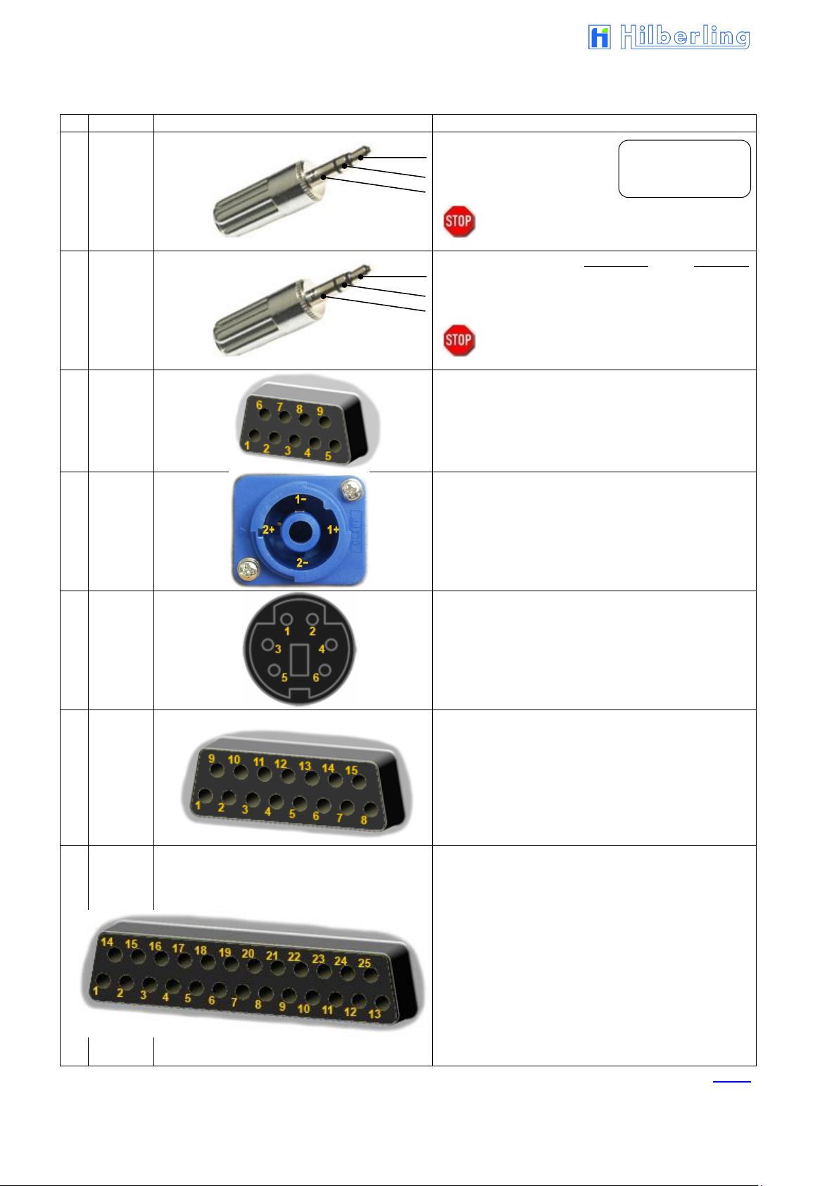
6
No
Label
Figure
Pin Assignment
J15
ext. SPKR
add.
1 Tip 60 kHz OUT MAIN RX
2 Ring 60 kHz OUT SUB RX
3 Sleeve GND
Caution: Using mono type plugs will shorten the
audio output and may damage the
transceiver
J16
ext. SPKR
alt.
STATUS: Audio NORM Audio SPLIT
1 Tip AUDIO OUT MAIN and SUB RX SUB RX
2 Ring <not connected>
3 Sleeve GND GND
Caution: Using mono type plugs will shorten the
audio output and may damage the
transceiver
J17
AUX-TX
(PTT/ALC)
1 PTT to HF-PA 6 EXT ALC IN (0 ... −10 V 2))
2 PTT EXT IN 7 PTT to HF-PA
3 PO FORWARD DC OUT 8 PO REFLECTED DC OUT
4 PTT to VHF-PA 1) 9 EXT TUN/PA READY=LOW
5 GND
1)
Circuit to ground 2) adjustable by P7
J18
DC
IN
2− 13.8 V DC (RX ; switched by relay)
1+ 50 V DC (PA ; switched by relay)
1− GND
2+ 13.8 V DC (Relay HN ; switched to GND by
PT8000 switch POWER
J19
Keyboard
1 DATA
2 <not connected>
3 GND
4 VCC
5 CLK
6 < not connected >
J20
AUDIO
IN/OUT
1 PTT AUDIO A 9 PTT AUDIO B
2 AUDIO DATA IN 3) 10 AUDIO DATA GND
3 AUDIO DATA GND 11 AUDIO DATA OUT
4 GND 12 GND
5 AUDIO OUT MAIN-RX 13 GND
6 GND 14 AUDIO OUT SUB-RX
7 GND 15 TP1
8 TP2
3)
0 dBm @ 600 Ohm
J21
Transverter
1 GND 14 AGC VOLTAGE MAIN
2 AGC VOLTAGE SUB 15 DATA EXT PA A
3 DATA EXT PA B 16 DATA EXT PA C
4 DATA EXT PA D 17 GND
5 +12V Transverter 1 4) 18 PTT Transverter 1 A
6 PTT Transverter 1 B 19 GND
7 +12V Transverter 2 4) 20 PTT Transverter 2 A
8 PTT Transverter 2 B 21 GND
9 < not connected > 22 < not connected >
10 DC EXT PA CONTROL 23 GND
11 GND 24 RS232 TX (CAT)
12 RS232 RX (CAT) 25 GND
13 GND
4)
max. 1 Ampere
Tab. 4
Connector for
Panorama Display /
Waterfall Diagram
4.1.3 Wiring J15 to J21

PT-8000A Operating Manual v2.01.10 7
No.
Label
Type
Description
1
MIC-PTT
Microphone Threaded Socket
8-pol
Microphone connector for Hilberling T9, AUDIO input 0 dBm @ 600 Ohm, and
MAIN-RX and SUB-RX AUDIO outputs.
2
PHONE
EIA-453 / IEC 60603-11
TRS 6.3 mm Socket
Headphones (impedance 8 ... 600 Ohm)
3
CW-KEY
EIA-453 / IEC 60603-11
TRS 6.3 mm Socket
Connector: – Keyer for CW (morse key/ keyer with paddle / automatic keyer)
– Control of the internal CW keyer
Tab. 5
No.
Label
Figure
Pin Assignment
1
MIC-PTT
0 dBm
1 MIC AUDIO IN
2 PTT
3 MAIN-RX AUDIO OUT (e.g. headset)
4 0 dBm AUDIO IN 1)
5 MIC AUDIO IN / DC +10 V internal
6 SUB-RX AUDIO OUT (e.g. headset)
7 MIC GND
8 PTT GND
1)
0 dBm @ 600 Ohm
2
PHONE
1 Tip + Audio OUT MAIN-RX
2 Ring + Audio OUT SUB-RX
3 Sleeve GND
NOTE: Audio for PHONE is derived from audio preamplifier
especially designed for phone operations.
Caution: Using mono type plugs will shorten the
audio output and may damage the
transceiver
3
CW-KEY
STATUS: Int. Keyer 2) Ext. Keyer 3)
1 Tip DOT CW-Key
2 Ring DASH <not connected>
3 Sleeve GND GND
2)
using the internal keyer (iambic or normal, P. 65)
3)
using an external keyer (P. 65)
Tab. 6
Electret Mic
1 2 3
Fig. 4
Dynamic Mic
4.2 Connectors at Front Panel
4.2.1 Connection Sockets 1 - 3
4.2.2 Wiring

8
No
Label
Type
Description
J1
AC
IEC-60320-C13 male connector
Input main power 90 – 260 V AC 50/60 Hz (cable P. 10 / Fig. 8)
J2
AUX
13.8 VDC
2x Socket 4 mm;
+ Clamp
Auxiliary output 13.8 V DC / 5 A
E
Socket 4 mm
Grounding wire – must be connected to PT-8000A transceiver (cable P.10 / Fig. 10)
Threaded Pin M6
Grounding stud – must be connected to PT-8000A transceiver and to station ground
J3
SPKR 8 Ω
EIA-453 / IEC 60603-11
TRS 3.5 mm Socket
Input audio signal MAIN- and SUB-RX/ only SUB-RX (Audio Norm/Split) from
PT-8000A socket J16 to built-in speaker; 4.5 W max. @ 8 Ω; (cable P. 10 / Fig. 11)
J4
DC
Cliffcon Socket
4-pol
Power connector for interconnection cable to PT-8000A (cable P. 10 / Fig. 9;
PT-8000A Socket J18)
AC-FUSE
Circuit breaker for AC mains at rear panel socket J1 rated 16 A @ 90 – 260 V AC
Tab. 7
E
J3
J4
J1
J2
Circuit breaker for AC/J1
Fig. 5
5 POWER SUPPLY HN-8000
5.1 General Description
Each PT-8000A is equipped with its power supply HN-8000, which delivers 13.8 V DC @ 8 A internal / 5 A external
and additional 50 V DC @ 14 A max., i.e. the overall performance is about 900 W.
Operating voltages from the mains can be in the range of 90 VAC to 260 VAC without any degradation in output
power. Only the efficiency will vary slightly. It complies with special regulations in some countries regarding power
factor compensation (PFC). The HN-8000 provides triple HF shielding and feedthrough filters.
In addition the HN-8000 provides an auxiliary output 13.8 VDC @ 5 A at the back panel, e.g. to deliver further
shack equipment.
5.2 Connectors at Rear Panel
Connection Sockets J1 - J4

PT-8000A Operating Manual v2.01.10 9
Make sure before connecting to mains to turn OFF (press down) both
mains switches (LINE and PA).
ON/OFF for DC Low Power
13.8 V (J4) PT-8000A RX and
DC AUX 13.8 V (J2) rear panel
ON/Off for DC Output
50 V (J4) PT-8000A
TX Power Amplifier
Automatic Fuse for DC-
Output 13.8 V / 5 A (J2)
AUX rear panel
Power Meter
PA DC-Input
Fig. 6
Fig. 7
Fig. 8
The power meter indicates the DC
5.3 Operating and Display Elements at Front Panel
input power of the final power
amplifier – hence computation of
efficiency could be easily done by
comparing RF-power out as
indicated on PT-8000 display and
DC-input shown here.
6 ACCESSORIES
6.1 Base Station Microphone Dynamic T9
6.2 Wiring / Cables
Best suited for all voice operations is the Hilberling Dynamic T9 especially designed
for the PT-8000A.
Isolated from any mechanical vibrations and designed to be used from more closer as
well as from greater distance it will always guarantee high fidelity audio and if desired
an extra punch to the signal.
It is equipped with a microphone preamp.
Impedance is 600 Ω @ 1 kHz. The acoustic characteristic is kidney-shaped.
Finish: Black anodized
AC line voltage cable (power grid ⬄ HN-8000) length approx. 1.7 m

10
Fig. 9
Fig. 10
Fig. 11
Fig. 12
Fig. 13a
Fig. 13b
DC power cable (HN-8000 ⬄ PT-8000A) length approx. 1.2 m
Ground cable (HN-8000 ⬄ PT-8000A) length approx. 1.0 m
Speaker cable (HN-8000 ⬄ PT-8000A) length approx. 0.9 m
Data cable (PT-8000A / USB-B ⬄ PC / USB-A) length approx. 1.8 m
6.3 Operating Manual and Software/Documentation CD-ROM
This manual version 2.01.xx
CD-ROM

PT-8000A Operating Manual v2.01.10 11
Power On
7 INSTALLATION / INITIAL OPERATION
7.1 Introduction
Prior to any operation of the PT-8000A read this Operation Manual carefully notably
before activating the transmitter.
The PT-8000A will be delivered with following presettings:
The preselectors of both RX are calibrated and all data are stored in RX-CPU
memory, which is buffered through a NiCd battery.
The transmitter is unlocked according to the band plans of that IARU region
(see Page 28) the PT-8000A is delivered.
The IARU region can be changed by software update.
Prior applying main power to the power supply HN-8000 please verify the following
points (7.2).
7.2 Cable Connections
7.3 Initial Settings
Please check at the rear panel of PT-8000A and HN-8000:
Antenna(s) is/are connected properly
Grounding stud is connected to station ground
Grounding wire is connected to both PT-8000A and HN-8000
DC cable is connected to both PT-8000A and HN-8000
For initial operation we recommend not to connect external amplifier, transverter or
devices for remote operation.
Please check at the front panel of HN-8000 (see Page 9):
Both switches (LINE and PA) are pushed down (off)
Please check at the front panel of PT-8000A (see Page 12):
Main switch (POWER) is pushed down (off)
Volume controls MAIN and SUB are set fully counter-clockwise
TX-PWR knob is set fully counter-clockwise
MIC-GAIN knob is set fully counter-clockwise
PROC knob is set fully counter-clockwise
Microphone T9 is connected
Connect power supply HN-8000 to main power
Turn on both LINE and PA on HN-8000
Turn on POWER at PT-8000A
It is up to the operator to switch PA off (switch PA at the HN-8000) during reception
only.

12
Function
Name
Description
Power ONOFF
POWER
All supply voltages from power supply HN-8000 are disconnected by this switch
Before turning ON verify settings for MIC-GAIN, PROC, TX-PWR and audio
volume settings for MAIN and SUB-RX are turned fully counter-clockwise.
After switching ON:
LED MAIN-RX will illuminate
LEDs of all pushbuttons will illuminate for 1 second (functional check)
Volume MAIN-RX
(PT + HN / PT only)
ONOFF Speaker
(PT only)
MAIN
Volume for audio MAIN-Receiver.
The RX is always turned on – audio is always present regardless of RX-status (active or in the
background – see below).
Pushing toggles the speaker of PT-8000A ON and OFF (s. P. 54).
Volume SUB-RX
(PT + HN / HN only)
ONOFF Speaker
(HN only)
SUB
Volume for audio SUB-Receiver.
The RX is always turned on – audio is always present regardless of RX-status (active or in the
background – see below).
Pushing toggles the speaker of HN-8000 ON and OFF (s. P. 54).
TFT-Display
÷
The display represents the primary means to control through “Softkeys” and to show all relevant data
for RX and TX operations.
Primary VFO Tuning Knob
active RX
÷
Tuning of VFO A/B of active RX. MAIN- and SUB-RX are always receiving. The term active is used in
the following context: Active means which RX (MAIN or SUB) is controlled by the main Display
(through soft switches) and which RX-Data is completely shown in the display.
Default setting: MAIN RX is the active RX.
Secondary VFO Tuning
Knob background RX
SUB VFO
Tuning of VFO A/B of RX, which is not the active one i.e. working in the Background (see above).
Default setting: SUB-RX is in the background
Set internal Reference
REF-SET
When operating the PT-8000A with its internal reference (10MHz-VCXO) this control will allow
calibration the VCXO. Tuning range ± 1 ppm (s. P. 55). The LED EXT-REF will illuminate if an
external reference signal is detected
Tab. 8
POWER
ONOFF
TFT Display
(s. P. 13)
Volume MAIN- and SUB-RX
Speaker ON⬄OFF
VFO (MAIN) Tuning
„active“ RX (s. P. 38)
VFO (SUB) Tuning
RX „in the background“
MAIN-RX / TX / SUB-RX
LED for status (s. P. 19)
Softkeys
(s. P. 13)
Fig. 14
Softkey menu
(s. P. 13)
MIC-GAIN
(s. P. 69)
PROC
(s. P. 69)
TX-PWR
(s. P. 70)
8 OPERATING AND DISPLAY ELEMENTS
In this chapter, the operating and display elements will be introduced.
8.1 Main Operating and Display Elements

PT-8000A Operating Manual v2.01.10 13
RX in the background
(limited access through controls)
selected VFO
active RX
(full access through
controls)
Note: Each VFO setting
includes bandwidth and
mode
RX: S-Meter
TX: RF Power Meter
Frequency + ID
(A/B)
Selected VFO
Bandwidth
@ 2nd IF Filter
selected VFO
RX ID
(MAIN/SUB)
Frequency + ID
(B/A)
Standby VFO
Operating Mode
Selected VFO
Operating
Mode
Frequency
Bandwidth of
2nd IF filters
DSP Filter Marker
Band Information
or Linear Scale
RX ID
(MAIN/SUB resp.
TRV/CONV)
Fig. 15
Softkeys
and
Softkey Menu
SWR Meter
Squelch Marker
Softkeys
Softkey Menu
ALC/COMP Meter
RF GAIN Marker
S Meter
8.2 TFT-Display
The display of the PT-8000A shows relevant data of both receivers, MAIN-RX and
SUB-RX, and the transmitter (TX):
All settings for the active RX
Main settings for the RX in the background
General Data for RX and TX
Functions to be activated by the adjacent keys (softkeys)
The six keys (so-called softkeys) right next to the display give access to the functions
named on the display at right border (in the Softkey Menu). The functions can be:
Activate a device function, selection of an adjustment option, call up of superior or
submenu.
Thus adapted softkey menus for almost all pushbuttons on the front panel allow direct
access to many allocated functions.

14
No
Module/Function
Mode
Description
Options
Display
Page
1
Antenna Preamplifier
HF
1.8 ... 30MHz
ON / OFF
AMP 10dB
59
VHF
50 ... 148MHz
ON / OFF
AMP VHF
61
2
Preselector
HF
1.8 ... 30MHz
ON / OFF
Preselect
59
3
Antenna Attenuator
HF ON / OFF
ATT 10dB
59
4
Antenna Connector
HF
Alternatively select
HF-ANT 1
ANT 1
59
HF-ANT 1+RX
ANT 1 RX
HF-ANT 2
ANT 2
VHF
Firmly assigned
VHF-ANT
ANT VHF
5
Noise Reduction
HF/VHF
DSP NR
ON / OFF
NR
48
Noise Blanker
RX NB
ON / OFF
NB
both ON
NR/NB
6
Notch Filter DSP
HF/VHF
DSP Notch Filter
ON / OFF
Notch 1
47
Notch Filter IF
IF Notch Filter
ON / OFF
Notch 2
both ON
Notch 1 2
7
12V Power Supply
VHF
For external purpose
ON / OFF
AMP-DC
61
Tab. 10
No
Module/Function
Description
Options
Page
1
VOX
Voice Operated TX
ON / OFF
70
2
3-Band TX-EQ Display
only visible if EQ Menu is active
64
3
Status-Field
Antenna and RX Adjustments
s. Tab. 10
14
4
Temperature MAIN-CPU
— 5 LEVELER
TX Audio Dynamic Controller
ON / OFF
63
6
PROCESSOR
TX IF-2 Compression
ON / OFF
69
7
EQUALIZER
TX 3-Band EQ
ON / OFF
64
8
Temperature PA
— 9 RIT / XIT
ON / OFF
43
10
SPLIT
ON / OFF
41/42
Tab. 9
Displayed Options
in the
Status Field
HF Mode
VHF Mode
1 2 3 4 5 6 5 6 7 4 1
Fig. 16
1 2 3 4 5 6 7 8 9
More indications
on the
Display
Fig. 17a
Fig. 17b
10

PT-8000A Operating Manual v2.01.10 15
BAND
HF Ham Radio Bands
(except for 60m band)
/
Numeric Buttons for Numerical
Frequency Input
ANT-TUNER
(MOX –Manually Operated Transmit)
DISPLAY
MENU I
– Software Update
– Calibration
– Brightness Display
– Voice Recorder
– Audio Norm / Split
MENU II
– Baud Rate USB
– Baud Rate J21
METER
– ALC / COMP (TX)
– S-Meter Scales
DSP
Activating:
Digital FILTERs
Automatic Multi NOTCH Filter
Automatic Noise Reduction
NR
FUNCTION
Automatic Gain Control AGC
Search over Memory
Channels SCAN **
VFO
Locking the VFOs
LOCK
Toggle VFO AB
Activating RIT/XIT
MODE
VHF Ham Radio Bands /
„0“- Key for Numerical Frequency Input
Basic Settings RX/TX
Memory Channels Write and – MEM
Filter Selection (Xtal and DSP)
STEP-VFO
Numerical Frequency Input - ENTER
Toggle MAIN-RX / SUB-RX
Channel storage management - CHANNEL
Operating Modes – SSB/CW
– AM/FM
– RTTY/DATA/Audio
Fig. 18
** Function temporarily disabled
8.3 Clustered Front Panel Controls
Various fix function keys (pushbuttons; in opposite to softkeys with variable functions, right of display, see Page 13)
are clustered in several button areas as shown below. Detailed description of functions starts at Page 20.
Pushing each (grey) button causes a beep; its volume is adjustable by the ZERO-BEAT knob (see next page).

16
NOISE BLANKER
Activate (OFF⬄ON)
Adjust Limit of Disturbance
IF-NOTCH FILTER
Activate (OFF⬄ON)
Adjust Frequency
SQUELCH
Keying (⇨OFF)
Adjust Threshold
RF-GAIN
Adjust RF-Gain
Deactivate AGC (ON⬄OFF)
TX-MONITOR
Adjust TX Volume
TX-DELAY
Adjust Switchover Time TX⇨RX
Adjustments / Settings for VOX Operation
Threshold
ANTI TRIP
DELAY
ZERO-BEAT
(Test Tone)
Keying 440Hz (⇨ON) FM-Mode: 1750 Hz)
Adjust Level
Adjust Level of Push-button Beep
MIC-GAIN
Adjustment Level
----------------------------VOX
Activate (OFF⬄ON)
MIC-PROCESSOR
(Speech Processor)
Activate (OFF⬄ON)
Adjust Compression Ratio 0 ... 20
dB
CW KEY SPEED
Adjust Automatic Key Speed CW
MAIN-RX
Adjust Audio Volume MAIN-RX
Deactivate Speaker PT-8000A
(ON⬄OFF)
SUB-RX
Adjust Audio Volume SUB-RX
Deactivate Speaker HN-8000
(ON⬄OFF)
RX FILTER WIDTH/SHIFT
Switch WIDTH⇨SHIFT⇨BFO
Adjust WIDTH/SHIFT/BFO
Select TX EQ Band
STEP-VFO / MEM/CH
Select VFO Decimal Place
Adjust VFO Frequency
Select MEM/CHANNEL
Select: TX Filter / VOICE REC Track /
HF Delay TX-Ext / TRV Operating Band
Fig. 19a
Fig. 19b
TX-POWER
(PA-Power)
Switch10W⬄200W
Adjust Power Level
8.4 Controls with Integrated Push-Button Function and Controls for Adjustments

PT-8000A Operating Manual v2.01.10 17
Fig. 20
Fig. 21
8.5 Side Panel Controls (Level Adjustments)
Sometimes it can be necessary to customize the input and output level of the PT8000A for special requirements. Boreholes in both left and right hand side enable the
access to trim potentiometers which allow manipulating the preadjustment of levels.
8.5.1 Input Level – Left Hand Side
P2 Microphone Sensitivity (Preadjustment)
Socket MIC-PTT Pin 1/5 (front panel);
fine adjustment with knob MIC
(see Page 69)
P6 Adjustment Level 0dBm Audio IN
Socket MIC-PTT Pin 4 (front panel)
The adjustment of sensitivity from MIC and Data
Input are twofold: Coarse adjustment (P2) is
done at an early stage right after the input
transformers. MIC gain settings from the front
panel controls amplifier and gain leveler circuit
on the TX board.
8.5.2 Output Level – Right Hand Side
P1 MAIN-RX Adjustment of audio volume
Headphones Speaker
Socket MIC-PTT Pin 3 (front panel)
Socket PHONE (Output Headphones)
(front panel)
P3 MAIN-RX Volume (Preadjustment)
Socket J20 Pin 5 AUDIO OUT MAIN-RX
(rear panel)
P4 SUB-RX Adjustment of audio volume
Headphones Speaker
Socket MIC-PTT Pin 6 (front panel)
Socket PHONE (Output Headphones)
(front panel)
P5 SUB-RX Volume (Preadjustment)
Socket J20 Pin 14 AUDIO OUT SUB-RX
(rear panel)
Please use an appropriate tool to adjust the controls to prevent any damage to the
variable resistors.

18
LED glows
Meaning
Page
TUNER
Antenna Tuner activated
68
START
Automatic Antenna Tuner Adjustment
activated
68
Tab. 11b
LED glows
Meaning
Page
MENU I *
unallocated
MENU II *
unallocated
METER *
unallocated
Tab. 11c
LED glows
Meaning
Page
FILTER
DSP Filter activated
45
NOTCH
Automatic DSP Multi-Notch Filter activated
47
NR
DSP Noise Reduction activated
48
Tab. 11d
LED glows
Meaning
Page
AGC
Automatic Gain Control disabled
50
SCAN **
Storage Frequency Scanning activated
52
Tab. 11e
LED glows
Meaning
Page
MEM
Memory mode activated
36
CHANNEL
Memory operation mode activated
34
DATA
Data mode activated
26
LOCK
VFO locking activated
44
RIT/XIT
RIT/XIT frequency deviation activated
43
Tab. 11a
Fig. 22a
Fig. 22c
Fig. 22b
Fig. 22d
Fig. 22e
* LED temporarily disabled
** Function temporarily disabled
8.6 Pushbuttons with LED Status Display
To inform about the status of several main functions of the PT8000A – in addition to display information – some pushbuttons
are equipped with LED, respectively the status of fundamental
operating conditions are indicated by LED.
Status displays as follows:
Further status displays:

PT-8000A Operating Manual v2.01.10 19
MAIN-RX
and
SUB-RX
Fig. 22f
Fig. 22g
8.7 LED Status Display
The three main modes of PT-8000A (MAIN-RX / SUB-RX / TX) are displayed with
colored LED.
The PT-8000A incorporates a transmitter and two independent receivers (MAIN RX
and SUB-RX). Both receivers are permanently operating. Even if a receiver is in the
background i.e. not fully accessible through all main controls the receiver is operating
with its last settings when it has been the active one.
One transmitter and two receivers are operated in three main modes:
MAIN-RX is active and SUB is working in the background
(green MAIN-RX LED glows)
SUB-RX is active and MAIN is working in the background
(yellow SUB-RX LED glows)
TX is operating (red TX-LED glows)
Note: The MAIN RX VFOs will always determine the transmit (TX) frequencies and
other operating parameters.
Exception Split-Mode: In this case the selected (displayed) SUB-RX-VFO determines the
transmit frequency (see Page 42).
The red LED EXT REF will be on when an external 10 MHz signal is representing the
frequency reference.
The internal 10 MHz system clock no longer takes effect.

20
Fig. 23
Settings of the
RX which is the
active one
Settings of the RX
background
Fig. 24
9 MAIN- AND SUB-RX OPERATIONS
The PT-8000A incorporates a transmitter and two independent receivers (MAIN-RX
and SUB-RX). Both receivers are permanently operating. Even if a receiver is in the
background i.e. not fully accessible through all main controls the receiver is operating
with its last settings when it has been the active one.
Using MAIN- and SUB-RX allows duplex operation mode.
Each of the two RX provides again two VFO: VFO A and VFO B. The active VFO is
called selected VFO, the other is called VFO in standby (s. P. 40).
Two controls are doubled, hence for these functions MAIN-/SUB-RX are always
accessible regardless of their status active or stand-by:
1. The selected VFO of the active RX (usually MAIN-RX) is always accessible through
MAIN tuning knob. The selected VFO of the RX working in the background (usually
SUB RX) is always accessible through SUB VFO knob.
2. The volume of MAIN- and SUB-RX is permanently adjustable through the
respective controls MAIN and SUB.
Both knobs have a push function:
Pushing MAIN will turn off PT-8000A speaker, pushing SUB will turn off HN8000 speaker. (see also Page 54).
The push button MAIN/SUB (located in the cluster MODE) toggles between the two RX
changing their status active or background.
After power on the PT-8000A the MAIN-RX is the active one (corresponding SUB-RX is
working in the background).
LED MAIN-RX and LED SUB-RX indicate which RX is the active one and so which is
accessible through all knobs and buttons on the front panel.
In the upper left corner the display shows the label of the active one (MAIN or
SUB).
Frequency, mode, filter bandwidths and S-meters are displayed for MAIN and
SUB respectively (see Figure 24).
Activation of noise reduction (NR), noise blanker (NB), DSP Filter, DSP-Notch, IF-
Notch, preamplifier, preselector and the squelch marker are displayed exclusively
for the active RX.
operating in the

PT-8000A Operating Manual v2.01.10 21
Example
When toggling between MAIN- and SUB-RX the actual settings of the controls used at
last are not transferred to the new active RX – instead the former settings of this RX are
the actual one – until they are overwritten by the respective control.
The squelch threshold set to the RX working in the background will stay the actual one
when this RX becomes the active – until one touches the squelch control to set the
threshold to a new setting.
The large S-meter is always allocated to the active RX. The smaller S-meter is
indicating the field strength of the RX working in the background.
Transmitting (TX) is only possible when MAIN-RX is the active one and SUB-RX is
working in the background.
When transmitting the SUB-RX may be used to monitor own RF-signal. Receiving with
SUB-RX on a separate antenna is limited however: Excessive field strength may trip the
protection circuits. Receiving at frequencies adjacent to the transmitting frequency may
be limited even by the superior dynamic characteristics of the PT-8000A receivers which are of course finite.

22
SSB/CW menu
Key
Operating Modes
Page
SSB / CW
USB / LSB and CW / CW–
s. b.
AM / FM
AM / AME USB / AME LSB and FM / FM RPT / FM RPT–
24
DATA
switchable „ operating sub mode“ DATA / RTTY / Audio
26
Tab. 12
Fig. 26
Fig. 25
10 MODES OF OPERATION MODE
In order to select different operating modes three push buttons (keys) are available in
the button area MODE:
When SSB/CW or AM/FM button is pushed the last selected mode (SSB/CW or
AM/FM) is memorized and reactivated.
When e.g. a band key with other adjustments were active before, the adjustments of
the buttons SSB/CW and AM/FM are preserved.
The display shows the activated mode to the left of frequency. The corresponding
softkey is shown inverse.
10.1 Single Side Band and Continuous Wave SSB / CW
10.1.1 SSB Single Side Band
Pushing SSB/CW button activates the allocated last used mode (USB, LSB, CW or
CW–) and will call up the SSB/CW menu.
If this is e.g. a SSB mode, a second press toggles to the last activated CW mode.
Upper Side Band;
the softkey will be displayed inverse (as shown here);
the display will show USB (to the left of frequency).
Lower Side Band;
the softkey will be displayed inverse;
the display will show LSB (to the left of frequency).
Continuous Wave normal mode (CW-pitch in USB);
the softkey will be displayed inverse;
the display will show CW (to the left of frequency).
Continuous Wave inverse mode (CW-pitch in LSB);
the softkey will be displayed inverse;
the display will show CW– (to the left of frequency).
Cyclic change of frequency tuning steps:
1 Hz 10 Hz 100 Hz 1 kHz

PT-8000A Operating Manual v2.01.10 23
Parameter
Value
Transceiver Operation
Frequency
BFO Frequency
Figure 27b
* Factory hardware extension
Fig. 27a
10.1.2 CW Continuous Wave
In CW (resp. CW–) mode the parameters Pitch, Width and BFO as well as their
specific value can be selected by using the knob WIDTH/SHIFT.
Pushing WIDTH/SHIFT knob will cycle between the parameters:
Pitch Width BFO
The chosen parameter and its current value are displayed left of status field in
combination with a small graphic:
Turning WIDTH/SHIFT knob will allow the following:
Pitch Varying the distance of the BFO frequency against the transceiver operation
frequency (and against the filter center frequency; transceiver operation
frequency and filter are linked).
The tone pitch of the received signal is changing.
Tuning range: 400 … 1000 Hz
Increments: 50 Hz (DSP on and off)
Width Select filter bandwidth to following values:
DSP on: 50 / 100 / 200 / 400 / 500 Hz
DSP off: 500 Hz (fixed) ( / 250 Hz with optional hardware
extension *)
BFO Shifting the filter (filter center frequency) against BFO frequency and
transceiver operation frequency (BFO frequency and transceiver operation
frequency are linked).
The tone pitch of the received signal does not change.
Tuning range: –250 Hz ... +250 Hz
Increments: 10 Hz (DSP on and off)
After power on the BFO offset is set to zero (default value).
The frequency of the monitoring TX signal (800 Hz ; volume adjustable by the Monitor
control, see page 71 ; 20.7 ; Fig. 109), is not influenced by the Pitch value.

24
FM menu
AM menu
Fig. 28
Fig. 29
10.2 AM / FM Amplitude Modulation / Frequency Modulation
Pushing AM/FM button activates the last used mode (AM, AME USB, AME LSB, FM,
FM RPT or FM RPT+) and will call up the allocated softkey menu (AM menu
respectively FM menu). Is this e.g. one of the AM modes, pushing AM/FM again
toggles to the last activated FM mode.
Amplitude Modulation (carrier and two sidebands);
the softkey will be displayed inverse (as shown here);
the display will show AM (to the left of frequency).
AM Synchronous (AME – AM Equivalent; carrier and Upper Sideband);
the softkey will be displayed inverse;
the display will show AME (to the left of frequency).
AM Synchronous (AME – AM Equivalent; carrier and Lower Sideband);
the softkey will be displayed inverse;
the display will show AME (to the left of frequency).
Cyclic change of frequency tuning steps:
1 Hz 10 Hz 100 Hz 1 kHz
Frequency Modulation (standard mode);
the softkey will be displayed inverse (as shown here);
the display will show FM (to the left of frequency).
FM repeater mode “standard”; the transmit frequency is lower (0 ... 2 MHz) than the
receive frequency; the softkey will be displayed inverse;
the display will show FM– (to the left of frequency).
FM repeater mode “inverse”; the transmit frequency is higher (0 ... 2 MHz) than the
receive frequency; the softkey will be displayed inverse;
the display will show FM+ (to the left of frequency).
Push and hold to monitor the repeater receive frequency (the softkey will be displayed
inverse); squelch is deactivated; only available if repeater mode is selected.
Push to set the frequency shift for repeater mode (the softkey will be displayed inverse
flashing; range 0 … 2 MHz (see next Page).
Cyclic change of frequency tuning steps:
1 Hz 10 Hz 100 Hz 1 kHz

PT-8000A Operating Manual v2.01.10 25
10.2.1 Repeater Mode – How to Set the Repeater Frequency Shift
When pushing SET RPT softkey (FM menu):
SET RPT softkey will flash inverse.
VFO display will show the actual transmit frequency.
Band- respectively linear scale changes (range 0 ... 2.000)
Set VFO to desired transmit frequency hence define the shift within a tuning range
from 0 … 2000 kHz.
The frequency resolution selected for the VFO will apply for this setting. It can be
modified by STEP-VFO softkey in the same menu.
Alternatively use STEP-VFO knob to set the frequency shift.
Pushing SET RPT again will terminate the SET RPT mode.
The frequency shift is used both for RPT– and RPT+.
Switch to a different operating mode will terminate the setting as well.
Numerical frequency shift input is not possible.
10.2.2 Repeater Mode – TX Frequency Display
Activation of PTT (pushing TX-ON button in the cluster ANT-TUNER respectively TX
pushbutton at Microphone T9) changes frequency display of the selected VFO:
Now the TX frequency – decreased (FM-) or increased (FM+) by adjusted frequency
shift - is shown.

26
DATA menu
Fig. 30
Alternative Termination
of DATA Operation
10.3 DATA Transmission (Digital Operation Modes)
The function DATA enables to send out signals which modulate the transmitter by
using following inputs:
0 dBm AUDIO IN (microphone socket MIC-PTT pin 4, see Page 7 Tab. 6)
AUDIO DATA IN (J20 AUDIO IN/OUT pin 2, see Page 6 Tab. 4)
This is basically possible with all modes – where appropriate. Thus why it is called
„operation sub mode“
When pushing DATA button located in the cluster MODE:
DATA-LED will stay off.
DATA menu will be called up.
In case this softkey is activated the signal at the 0dBm input (MIC-PTT Pin 4)
will be transmitted when PTT is switched; the softkey will be displayed
inverse; DATA-LED will turn on.
In case this softkey is activated the signal at the AUDIO DATA IN input (J20
Pin 2+3/10) will be transmitted when PTT is switched; the softkey will be
displayed inverse as shown here; DATA-LED will turn on.
RTTY operation; the filter will be shifted according to the frequency offset of
modulation tones (2125 Hz / 2295 Hz); the softkey will be displayed inverse; the
display will show RTTY (to the left of frequency).
This softkey toggles the source of audio signals at AUDIO DATA OUT output (J20 Pin
11+3/10) between MAIN-RX and SUB-RX (display accordingly OUT MAIN or
OUT SUB).
In case this softkey is activated the signal at the AUDIO DATA IN input (J20 Pin
2+3/10) will be transmitted when PTT is switched by an external software command
(USB interface); the softkey will be displayed inverse.
TX 0dBm, TX DATA and DATA Mike are only working alternatively.
DATA mode may be selected in all operating modes.
Only when DATA mode is selected a PTT signal can be fed through USB interface
(handshake signal).
In case the DATA softkey menu is displayed pushing DATA will terminate the currently
active DATA mode (TX 0dBm,TX DATA or DATA Mike).
If the menu is not displayed pushing DATA will call it up and only a second push will
terminate the currently active DATA mode:
DATA-LED will turn off.

PT-8000A Operating Manual v2.01.10 27
Fig. 31
11 SELECTING FREQUENCIES
To select or change a frequency there are the following options:
Select with band buttons (see below).
Numerical input (see Page 32).
Recall from a memory channel (see Page 34).
11.1 Select with BAND Buttons
Pushing a band pushbutton selects one of two stored frequencies
within the desired band (see Table 13 and 14 / Page 28).
The MF and each HF amateur radio band (excl. 60 m) is allocated to
a pushbutton in the cluster BAND.
The VHF amateur radio bands and the RX-only range above 110 MHz
are accessible by button 0 VHF in the cluster MODE and additional
select in the VHF softkey menu.
Each band button stores two frequencies exclusively for this band. Pressing the button
again will toggle between the last two frequencies used within this band.
The last used frequency within a band is stored automatically, so the stored frequency
will change continuously when tuning within the band with VFO knob or STEP-VFO
knob.
In case the BAND limits are exceeded through tuning the last valid frequency that has
been stored will remain. Press button again for return the PT-8000A to the last used
frequency.
The two stored frequencies of a band are correlated to each VFO. Selecting the
alternate VFO will give access to another two frequencies in that band (which were
used with this VFO). Of course this is applicable for both MAIN- and SUB-RX.
Mode, filter adjustments (width/shift), antenna and tuning increments (STEP VFO) are
stored along with the respective frequency.
A numerical input of a frequency (see Page 32) within the selected band will overwrite
one of the two stored frequencies (the last frequency used).
11.1.1 HF Amateur Radio Bands
Pressing e.g. button 14 5 (located in the cluster BAND) selects the last used
frequency within the 20 m band of the selected VFO.
The VFO menu (see Page 41) will be displayed.
Pressing again will toggle between the last two frequencies used within this band.
Two more frequencies are allocated to the „stand-by“-VFO.

28
Button
Band
Sign
Frequency Range
1.8 1
160 m
MF
1.8101 /1.800
2,3
...
2.000 MHz
3.5 2
80 m
HF
3.500
...
3.8001 / 4.0002 / 3.9003 MHz
–
60 m
5.260
...
5.410 MHz
7.0 3
40 m
7.000
...
7.2001 / 7.300
2,3
MHz
10 4
30 m
10.100
...
10.150 MHz
14 5
20 m
14.000
...
14.350 MHz
18 6
17 m
18.068
...
18.168 MHz
21 7
15 m
21.000
...
21.450 MHz
24 8
12 m
24.890
...
24.990 MHz
28 9
10 m
28.000
...
29.700 MHz
Tab. 13
Button
Band
Sign
Frequency Range
0 VHF → Softkey 50
6 m
VHF
50.000
...
52.0001 / 54.000
2,3
MHz
0 VHF → Softkey 70
4 m
70.0001
...
70.5001 MHz
0 VHF → Softkey 144
2 m
144.000
...
146.0001 / 148.00
2,3
MHz
0 VHF → Softkey 110
RX Range
110.000
...
143.999 MHz
Tab. 14
1
= IARU Region 1 2 = IARU Region 2 3 = IARU Region 3
1
= IARU Region 1 2 = IARU Region 2 3 = IARU Region 3
The following MF/HF amateur radio bands – slightly modified depending on IARU
region the TRX will operate – are defined in the PT-8000A software as TX bands. They
are directly selectable with band pushbuttons (except 60 m):
11.1.2 VHF Amateur Radio Bands
Pushing button 0 VHF located in the cluster MODE will call up the VHF menu (see
Page 29) and will recall the last used frequency on the last used VHF band (50 MHz,
70 MHz, 144 MHz or 110 MHz, the corresponding softkey will be displayed inverse).
Pushing the button of the current band (the softkey is shown inverse) switches to the
second frequency stored in this band.
The following VHF amateur radio bands are defined as TX bands in the PT-8000A and
selectable via button 0 VHF and the respectively assigned softkey (plus one additional
RX-only range):
If a transverter has been used the last time while VHF operation pushing button 0 VHF
will activate the transverter again, the corresponding frequency will be shown on the
display and the softkey Trans will be displayed inverse.

VHF menu
Fig. 32
PT-8000A Operating Manual v2.01.10 29
Select 2 m band; the softkey will be displayed inverse (as shown here); pressing this
key again will toggle between the last two frequencies used within this band.
Select RX Range 110 ... 143.990 MHz; the softkey will be displayed inverse; pressing
this key again will toggle between the last two frequencies used within this band.
Select 4 m band; the softkey will be displayed inverse; pressing this key again will
toggle between the last two frequencies used within this band.
Select 6 m band; the softkey will be displayed inverse; pressing this key again will
toggle between the last two frequencies used within this band.
Transverter select menu will be called up (see next Page); in case a Transverter is
already selected the softkey is displayed inverse.
VFO menu will be called up (see Page 41).
Only one transverter can be activated at a time for each of the receivers. To operate
two transverters MAIN- and SUB-RX must be allocated to different transverters.
It should be noted that it is not possible to form a transceiver with SUB-RX. Hereby the
transverter only works as a converter.

30
Transverter Band Select menu
Transverter Select menu
Fig. 33
Fig. 34
11.1.3 Transverter Operation
Pushing softkey Trans (VHF menu) will call up the Transverter Select menu. If a
transverter is already selected the softkey is displayed inverse.
Return to VHF menu (see previous Page).
Select transverter #1; the softkey will be displayed inverse; pushing again will call up
the Transverter Band Select menu (see below).
Select transverter #2; the softkey will be displayed inverse; pushing again will call up
the Transverter Band Select menu (see below).
VFO menu will be called up (see Page 41).
If transverter 1 is selected (displayed inverse) pushing again softkey Trans 1 will call up
the Transverter Band Select menu (applies accordingly to Trans 2)
Return to Transverter Select menu (see above).
Activates 2 m band (144 ... 148 MHz); the softkey will be displayed
inverse; push again and hold allows to select a transverter operating
band using STEP-VFO knob (see Page 31).
Activates 6 m band (50 ... 54 MHz); the softkey will be displayed inverse (as shown
here); push again and hold allows to select a transverter operating band using STEPVFO knob (see Page 31).
Activates 10 m band (28 … 30 MHz); the softkey will be displayed inverse; push again
and hold allows to select a transverter operating band using STEP-VFO knob (see
Page 31).

PT-8000A Operating Manual v2.01.10 31
No.
Frequency Range
1
432
...
434 MHz
2
435
...
437 MHz
3
1.268
...
1.270 GHz
4
1.296
...
1.298 GHz
5
2.320
...
2.322 GHz
6
3.400
...
3.402 GHz
7
3.456
...
3.458 GHz
8
5.760
...
5.762 GHz
9
10.368
...
10.370 GHz
10
10.450
…
10.452 GHz
11
24.048
…
24.050 GHz
12
47.088
...
47.090 GHz
13
75.976
...
75.978 GHz
Tab. 15
Changing of allocated
transverters
Transverter Operation
Frequency Bands
Fig. 35
If one of the softkeys (144/50/28) is pushed and held, the transverter operation
frequency band is displayed instead of the standby VFO frequency, see Figure 35.
Using control STEP-VFO / MEM/CH
gives access to all transverter
operation frequency bands as listed
below (Table 15).
When releasing the transverter softkey
the new frequency band is transferred
and will be stored.
The following 13 transverter operation frequency bands are available:
When the PT-8000A operates in transverter mode the transmitter output is directed to
the TX-ext. connector on the rear panel (see Page 5 / Table 3 / socket J14).
A transverter for one of the bands shown in Table 15 must be selected so that it can
operate properly with drive power 10 m, 6 m or 2 m.
Maximum power level at J14 is +20 dBm.
Hooking up multiple transverters requires external distribution of TX signals from TX-ext.
J14.

32
ENTER menu
Fig. 37a
Fig. 38
MHz
kHz
Hz
MHz
kHz
Fig. 37b
Can not be
edited
Fig. 36
11.2 Numerical Frequency Input ENTER
Pushing button ENTER located in the cluster MODE will call up the ENTER menu and
will activate the numerical frequency input:
The frequency display will show blanks for all digits. A cursor indicates („_“) which
digit can be edited.
The number of blanks/digits are shown depends on the resolution selected by using the
Softkeys STEP , STEP or STEP VFO (s. P. 41). E.g. the resolution is 1 kHz the
frequency will be displayed as follows:
Pushing the respective numbers from 1.8 1 to 28 9 allocated to the BAND
buttons (located in the cluster BAND) and 0 VHF (located in the cluster MODE)
will insert the digits from left to right.
Pushing button ENTER (cluster MODE or softkey) again will complete the input;
the RX transfers the frequency; the VFO menu will be displayed:
Numerical input will be aborted;
the last used frequency will be displayed instead;
the last used softkey menu will be called up.
The cursor will jump to the next left position; the last digit input will be deleted; a
leading empty digit will reappear.
Frequency input will be completed;
the RX transfers the frequency (function is the same as key ENTER in the cluster MODE
does);the VFO softkey menu will be displayed.
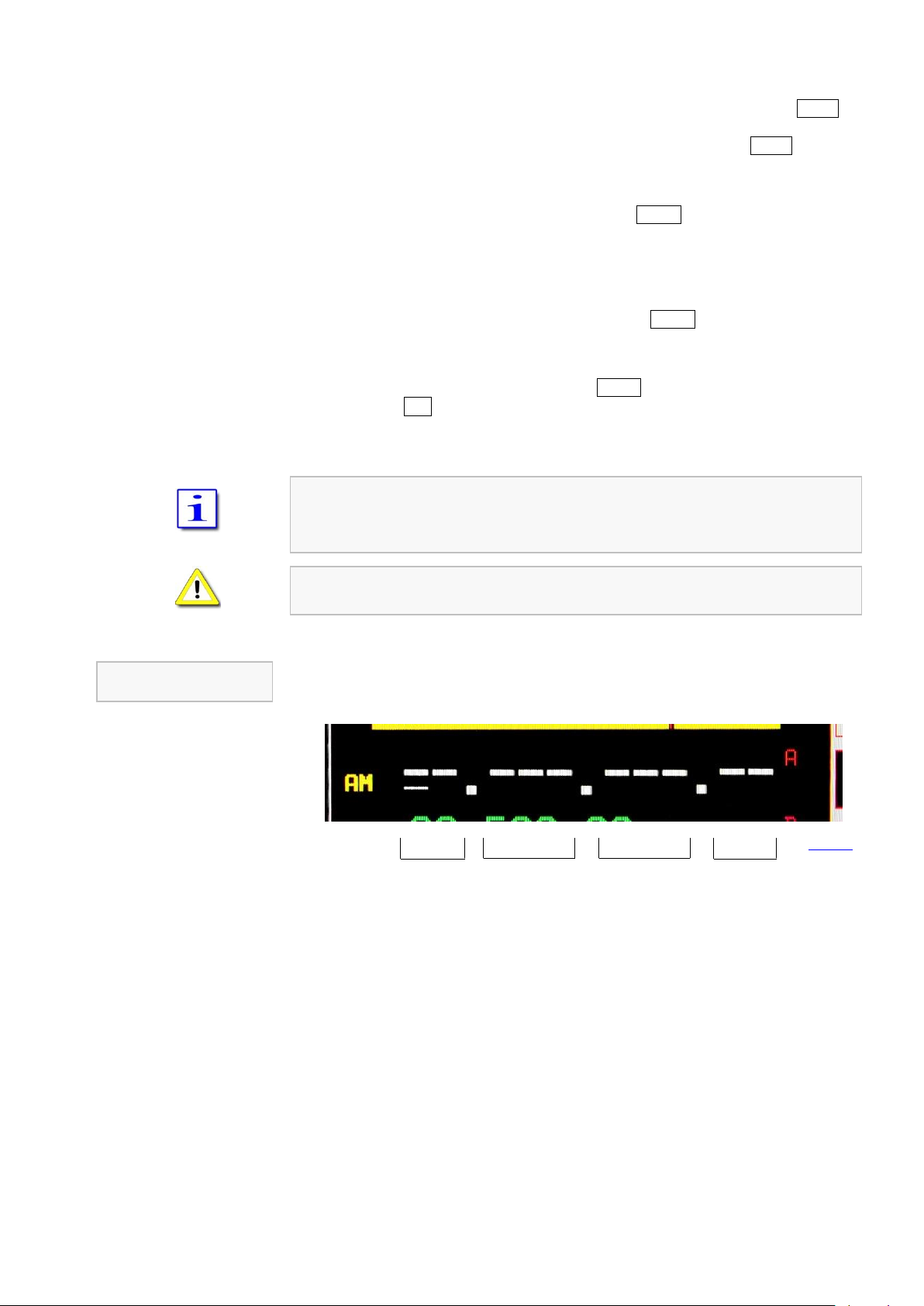
PT-8000A Operating Manual v2.01.10 33
Numerical Input
Transverter Operation
MHz
kHz
Hz
GHz
Fig. 39
Because the numerical input always starts with the 100 MHz digit possibly the 0 VHF
button first must be pushed. So this digit disappears and the Cursor jumps one digit to
the right to the 10 MHz digit. These can be deleted as well by pushing 0 VHF button
again, the cursor jumps to the 1 MHz digit, etc.
It is not necessary to key all digits (e.g. “0”). Pushing ENTER after the last digit will set
all lower digits to zero. After a valid numerical input is acknowledged the frequency will
be displayed and the respective RX will operate on that frequency.
In case the least significant digit is typed in the numerical input is terminated and the
frequency is transferred to the respective VFO (Pushing ENTER is not required). The RX
operates with the new frequency.
In case the input is not acknowledged through ENTER or completely input or not
aborted through ESC, after a period of 10 seconds without any activity the numerical
input will be terminated and the last frequency used will be selected again. The last
used softkey menu will be called up.
If the entered frequency is outside of RX frequency ranges of the PT-8000A the VFO
will jump to the upper border of the next lower RX frequency range. If input frequency is
< 9 kHz it will jump to 9 kHz.
In case the input frequency is a valid BAND frequency one of the two stored
frequencies of this BAND will be overwritten by the numerical input.
In transverter operation two additional digits will be displayed for 1 and 10 gigahertz
range:
In this case the 1 Hz digit is not available for numerical input.

34
CHANNEL menu
Fig. 41
Fig. 40
** Function temporarily disabled
11.3 Channel Operation
11.3.1 Recall of Stored Frequencies CHANNEL
Recalling of VFO adjustments (frequency, mode and filter bandwidth) will be done by
pushing button CHANNEL located in the cluster MODE. It gives access to 3 banks of
memory each storing 99 channels provided by PT-8000A.
When a memory channel is selected the stored adjustments are active with the current
RX immediately. They can be transferred to the VFO permanently (CHAN⇨VFO) or
can be restored with changed parameters as well (overwriting) (SET MEM).
When pushing CHANNEL:
The last used channel will be activated and the RX operates with its frequency and
the other stored adjustments.
CHANNEL LED will be on.
CHANNEL menu will be called up (see below).
The frequency display of the standby VFO will be substituted by information about
the active channel (see Page 35 Figure 42).
When CHANNEL function is active toggling between MAIN-/SUB-RX and VFO-A/B is
inhibited.
Select bank #1; the softkey will be displayed inverse.
Select bank #2; the softkey will be displayed inverse.
Select bank #3; the softkey will be displayed inverse (as shown here).
Select (earmark) actual channel for SCAN mode **; this can also be done by pushing
the knob MEM/CH / STEP-VFO.
Writing channel to selected VFO from active RX. The CHANNEL mode will be
terminated and the VFO menu will be called up (see Page 35).
Writing current VFO adjustments to selected memory channel; if this channel was
selected for SCAN mode the earmark will be deleted; it must be selected again if
required (see also Page 36 – MEM).

PT-8000A Operating Manual v2.01.10 35
Displayed Memory Channel
Information
Termination of
CHANNEL Operation
Bank #
Channel #
Mode
Bandwidth
Stored Frequency
SCAN Marker
Fig. 42
CHANNEL Operation
** SCAN Function temporarily disabled
After selecting the memory bank through pushing softkeys BANK 1, BANK 2 and
BANK 3 the control MEM/CH / STEP-VFO gives access to 99 memory channels by
turning.
Both MAIN- and SUB-RX can read and write into the memory.
The frequency resolution of the stored value depends on the resolution of the current
frequency. It will be written to the VFO in the same manner.
Channels which are selected for SCAN operation (see chapter 16, Page 52) are
marked by an asterisk (*). If the frequency of the marked channel lies within the SCAN
boundaries it will be used for SCAN operations. **
If there was no memory content written to the VFO by pushing softkey CHAN⇨VFO,
pushing CHANNEL again will terminate CHANNEL operation.
If the CHANNEL menu is not displayed, pushing CHANNEL will call it up and second
pushing will terminate CHANNEL operation:
The last used VFO frequency will be activated.
VFO menu will be called up.
CHANNEL LED will turn off.

36
MEM menu
Fig. 43
Fig. 44
11.3.2 Storage of Frequencies MEM
Pushing button MEM located in the cluster MODE will store the frequency and
additional VFO values of the active RX to one of the 297 memory channels organized
in three banks with 99 memory channels each bank.
Other than CHANNEL operation (see Page 34) the RX will stay on its current VFO
adjustments while MEM functions are executed.
When pushing MEM:
MEM LED will be on.
MEM menu will be called up (see below).
The frequency display of the standby VFO will be substituted by information about
the selected memory channel (see Page 37 Figure 45).
When MEM function is activated toggling between MAIN- and SUB-RX is inhibited;
same with toggling VFO-A and B.
Select bank #1; the softkey will be displayed inverse.
Select bank #2; the softkey will be displayed inverse.
Select bank #3; the softkey will be displayed inverse (as shown here).
Writing current VFO adjustments to selected memory channel; if this channel was
selected for SCAN mode the earmark will be deleted; it must be selected again if
required (see also Page 34 – CHANNEL).
Pushing softkey BANK 1, BANK 2 and BANK 3 gives access to the banks. Use
MEM/CH / STEP-VFO to select desired memory channel (0 … 99).

PT-8000A Operating Manual v2.01.10 37
Termination of
MEM Operation
Bank #
Channel #
Mode
Bandwidth
Stored Frequency
SCAN Marker
Fig. 45
Displayed Memory Channel
Information
MEMory Operation
Mode and filter bandwidth are stored as well.
When MEM function will be activated, at first always the last used bank # is selected
and displayed with its first (lowest number) empty memory.
In case all memory channels are written the last used memory channel will be
displayed and when pushing VFO⇨MEM overwritten.
When overwriting a memory channel there is no warning.
Memory channels are accessible from both MAIN- and SUB-RX.
If the MEM menu is displayed pushing MEM will terminate this mode and the VFO
menu will be displayed.
If the MEM menu is not displayed pushing MEM will call it up and a second push will
terminate MEM operation:
VFO menu will be called up.
MEM LED will turn off.
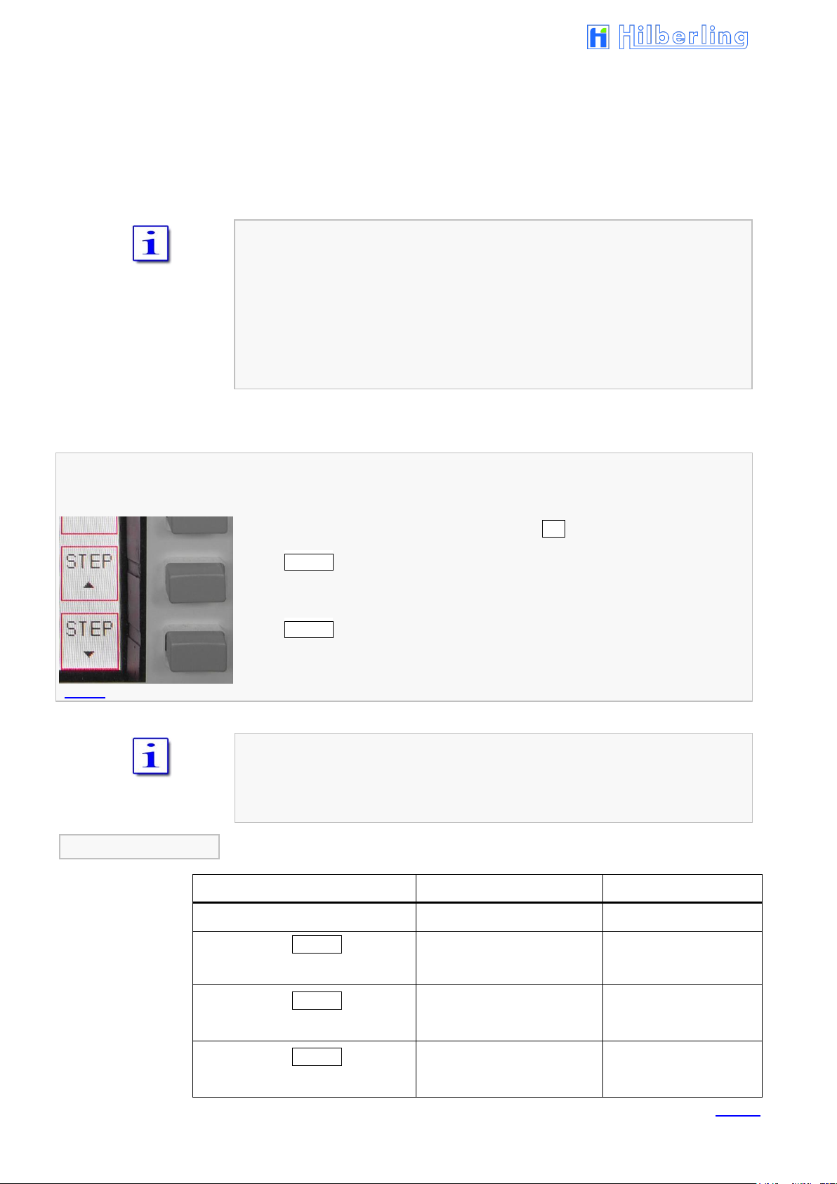
38
VFO menu (detail)
Displayed VFO Frequency
Transceiver Frequency
Tuning Increments
1.234.567
1,234.567 kHz
1 Hz
1st pushing STEP
1.234.560
1,234.560 kHz
10 Hz
2nd pushing STEP
1.234.500
1,234.500 kHz
100 Hz
3rd pushing STEP
1.234.000
1,234.000 kHz
1 kHz
Example
Tab. 16
Fig. 46
11.4 VFO Main Tuning Knob (active RX) and SUB VFO Tuning Knob (RX in the Background)
Primary means of tuning the active RX (MAIN- or SUB-RX) is the Main Tuning Knob
VFO. With a full rotation it generates 512 steps, so that depending on the chosen
tuning increments 512 Hz, 5.12 kHz, 51.2 kHz or 512 kHz can be run through.
The Tuning Knob SUB VFO generates 256 steps with a full rotation, so that depending
on the chosen tuning increments 256 Hz, 2.56 kHz, 25.6 kHz or 256 kHz can be run
through.
General frequency coverage of both RX is 9 kHz to 30 MHz, 50 to 54 MHz, 69.9 MHz
to 70.7 MHz and 110 MHz to 148 MHz. Due to the frequency scheme of the PT8000A the ranges between them are blanked out.
Transmit operation is only possible on the allocated amateur radio bands of that IARU
region in which one the TRX will operate after delivery (see Page 28 / Table 13 and
14).
In case the transmit boundaries are to be modified (commercial application; signal
generator operation; new amateur radio frequencies) please contact Hilberling GmbH
for further information about a software update.
The tuning increments of the VFO are adjustable through STEP selection, which is
allocated to the softkey menu VFO.
If the VFO menu is not displayed, push button VFO A/B (see Page 40).
Softkey STEP (towards fine tuning) decreases the tuning increments by power of 10.
Additional digits appear at the VFO frequency readout.
Softkey STEP (towards coarse tuning) increases the tuning increments by power of
10. Lesser digits appear at the VFO frequency readout.
Selectable increments are 1 Hz / 10 Hz / 100 Hz / 1 kHz.
Digits below the selected tuning width are set to 0 and will be displayed in dark grey.

PT-8000A Operating Manual v2.01.10 39
Fig. 48
Fig. 47
Each mode has been allocated a default tuning increment setting:
FM: 100 Hz
SSB / CW / AM: 10 Hz
Changing the operating mode will reset the current setting to default values.
11.5 STEP-VFO Control
Operation with knob STEP-VFO allows VFO tuning with further increments.
The STEP-VFO Control is placed in the cluster MODE. The control enables tuning in
10 kHz, 100 kHz and 1 MHz increments.
Pushing the knob activates the STEP-VFO function:
A cursor appears at the 100 kHz digit of the frequency display:
Turning the knob will now tune the VFO by 100 kHz steps.
Pushing the knob a second time will move the cursor to the 10 kHz digit. Turning
the knob will result in tuning the VFO by 10 kHz steps.
Pushing the knob a third time will move the cursor to the 1 MHz digit – hence
tuning can now be established by 1 MHz steps.
Pushing the knob again will result in a movement of the cursor again to the 100
kHz digit, then 1 kHz, 1 MHz, and so on.
Neither pushing the knob nor turning the control for more than 3 seconds will
terminate the STEP-VFO function. If re-activated by pushing the knob the cursor will
appear at the last used position.
When power up the PT-8000A and STEP-VFO will be activated the cursor will initially
occur at the 100 kHz position.

40
active RX
(shown: MAIN-RX)
selected VFO (shown: A)
RX in the background
(shown: SUB-RX)
selected VFO (A or B)
Fig. 49
Fig. 51
Fig. 50
11.6 VFO Management
Both receivers (MAIN- and SUB-RX) have its own two VFOs – VFO A and
VFO B. Switching between VFO A and VFO B is established through VFO
A/B pushbutton. The button is located in the cluster VFO.
In addition to frequencies the VFOs store filter bandwidth and
operation mode.
When pushing button VFO A/B:
In case the VFO softkey menu is already displayed the active RX will change its
VFO (A⇨B or B⇨A).
If a different softkey menu is displayed the first push will call up the VFO menu.
The second push will alter the VFO A and VFO B.
Both frequencies displayed for the active RX will alter its
position. The white display always shows the selected VFO. The
VFO can be identified through the red nominators A
respectively B.
The smaller green display always shows the alternate VFO that
is in standby mode.
Only the SUB-RXs selected VFO frequency is displayed without its identifier A or B.

PT-8000A Operating Manual v2.01.10 41
VFO menu active RX: MAIN-RX with selected VFO A
VFO menu active RX: SUB-RX with selected VFO B
Fig. 52
Fig. 53
Example
Example
In case the MAIN-RX is the active RX and its VFO A is the selected VFO, the VFO menu
is displayed as follows:
The frequency of the selected VFO (shown: A) from the active RX (shown: MAIN-RX) will
be copied to the selected VFO (without identifier) from the RX in the background
(shown: SUB-RX).
The frequency of the selected VFO (without identifier) from the RX in the background
(shown: SUB-RX) will be copied to the selected VFO (shown: A) from the active RX
(shown: MAIN-RX).
The frequency of the selected VFO (shown: A) from the active RX (shown: MAIN-RX) will
be copied to the VFO in standby (shown: B) from the active RX (shown: MAIN-RX).
VFO SPLIT: The Frequency of the selected VFO (shown VFO A) from the active MAINRX will be used for RX; the selected VFO (without identifier) from the SUB-RX in the
background will determine the TX frequency (see also P. 42); to the left of the Display
SPLIT will be displayed; the softkey will be displayed inverse.
Softkey STEP (towards fine tuning) decreases the tuning increments by power of 10.
One more digit will appear at the VFO frequency readout each pushing.
Softkey STEP (towards coarse tuning) increases the tuning increments by power of
10. One digit less will be shown at the VFO frequency readout each pushing.
SPLIT operation using VFO A and VFO B (= VFO SPLIT) is only possible with the
MAIN-RX (the active RX. SUB-RX is in the background).
In case the SUB-RX is the active RX and its VFO B is the selected VFO, the VFO menu
is displayed as follows:
The frequency of the selected VFO (shown: B) from the active RX (shown: SUB-RX) will
be copied to the selected VFO (without identifier) from the RX in the background
(shown: MAIN-RX).
The frequency of the selected VFO (without identifier) from the RX in the background
(shown: MAIN-RX) will be copied to the selected VFO (shown: B) from the active RX
(shown: SUB-RX).
The frequency of the selected VFO (shown: B) from the active RX (shown: SUB-RX) will
be copied to the VFO in standby (shown: A) from the active RX (shown: SUB-RX).
VFO SPLIT is not applicable if SUB-RX is the active one; for SPLIT operation the MAINRX must be active, see above.
Softkey STEP (towards fine tuning) decreases the tuning increments by power of 10.
Additional digits appear at the VFO frequency readout.
Softkey STEP (towards coarse tuning) increases the tuning increments by power of
10. Lesser digits appear at the VFO frequency readout.

42
11.7 SPLIT Operation
VFO SPLIT operation in the PT-8000A is realized by using the MAIN and the SUB-RX.
The selected VFO from MAIN-RX determines the RX frequency; the selected VFO from
SUB-RX determines the TX frequency.
To enable VFO SPLIT operation, MAIN-RX must be the active RX and SUB-RX operates
in the background.
The PT-8000A stays in the current operation mode of MAIN-RX when transmitting,
even though there is selected a different mode in SUB-RX. Only the frequency of SUBRX will be used.
Procedure:
Tune with the active VFO from MAIN-RX to the desired receive frequency.
Tune with the active VFO from SUB-RX to the desired transmit frequency.
When pushing softkey SPLIT (VFO menu):
When pushing PTT, the desired frequency from SUB-RX will be used for transmit
instead of the receive frequency of MAIN-RX.
To the left of the Display, below operation mode indicator, SPLIT will be displayed
The softkey will be displayed inverse
Pushing SPLIT again will terminate VFO SPLIT operation.
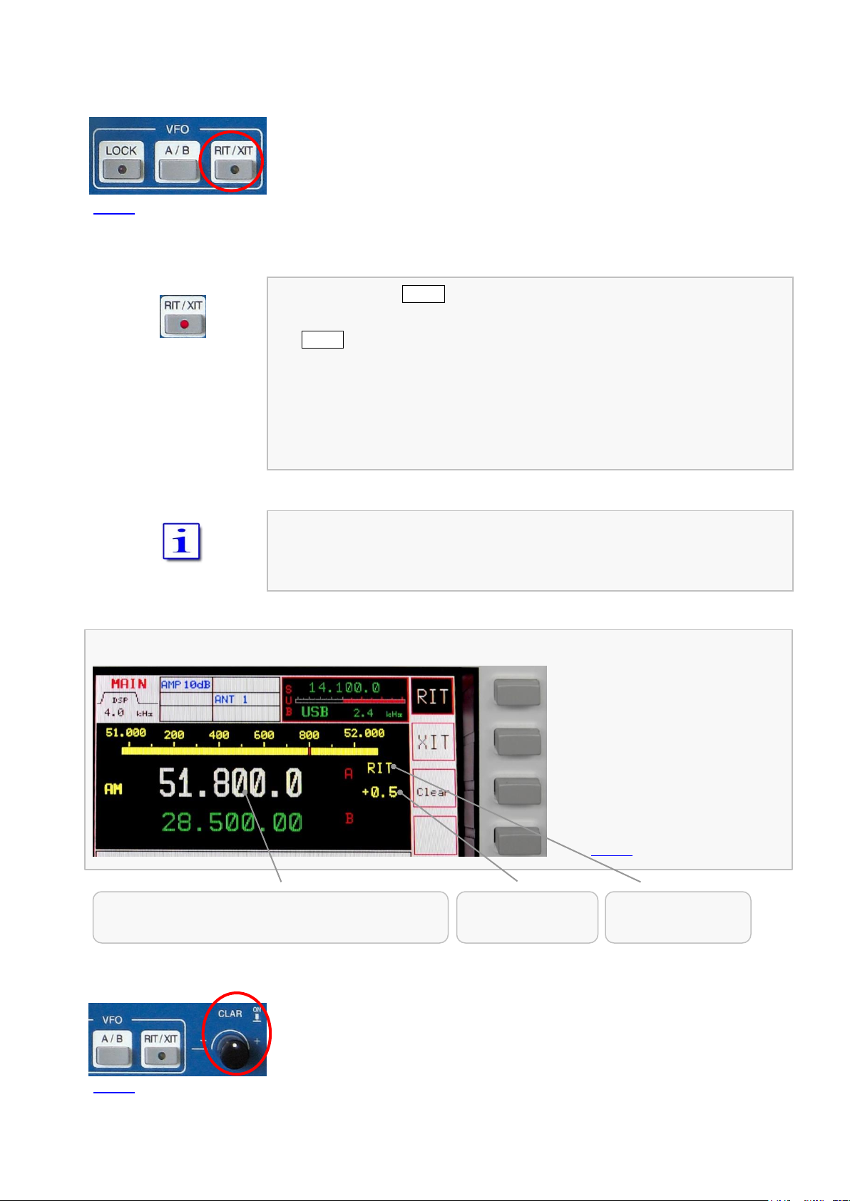
PT-8000A Operating Manual v2.01.10 43
RIT/XIT menu / RIT/XIT offset
Fig. 55
RIT: Resulting RX Frequency when receiving
XIT: Resulting TX Frequency when transmitting
Offset Frequency
RIT / XIT
Status
RIT or XIT
Fig. 54
Fig. 56
11.8 RIT / XIT Operation
RIT (Receiver Incremental Tuning) allows to shift/adjust the receiving frequency
plus/minus 9.999 kHz against the transmit frequency. The MAIN-RX and the transmitter
are no longer „transceive“. RIT is only possible with the MAIN-RX.
XIT (Transmitter Incremental Tuning) allows to shift/adjust the transmitting frequency
plus/minus 9.999 kHz against the receiving frequency. The MAIN-RX and the
transmitter are no longer „transceive“. RIT is only possible with the MAIN-RX.
When pushing button RIT/XIT located in the cluster VFO:
RIT/XIT LED will be on.
RIT/XIT menu will be called up. RIT or XIT will be displayed inverse (after power-on
RIT will be activated = power-on default).
CLAR knob will be activated (functions see below, Fig. 56).
RIT or XIT and the offset frequency will be displayed right next to the frequency
(after power-on RIT will be activated; the offset frequency will be set to 0.000 kHz
= power-on default).
In case of RIT is activated, the display will show the RX frequency affected by offset
frequency (= resulting RX frequency). When TX operation during XIT activation, the
display will show the TX frequency affected by offset frequency (= resulting TX
frequency).
Activation RIT (as shown here)
Activation XIT
Reset the offset to zero
Turning knob CLAR (clarifier) located right next to the cluster VFO will adjust the
offset frequency.
Pushing knob CLAR will toggle the offset frequency between selected value and
0.000 kHz.
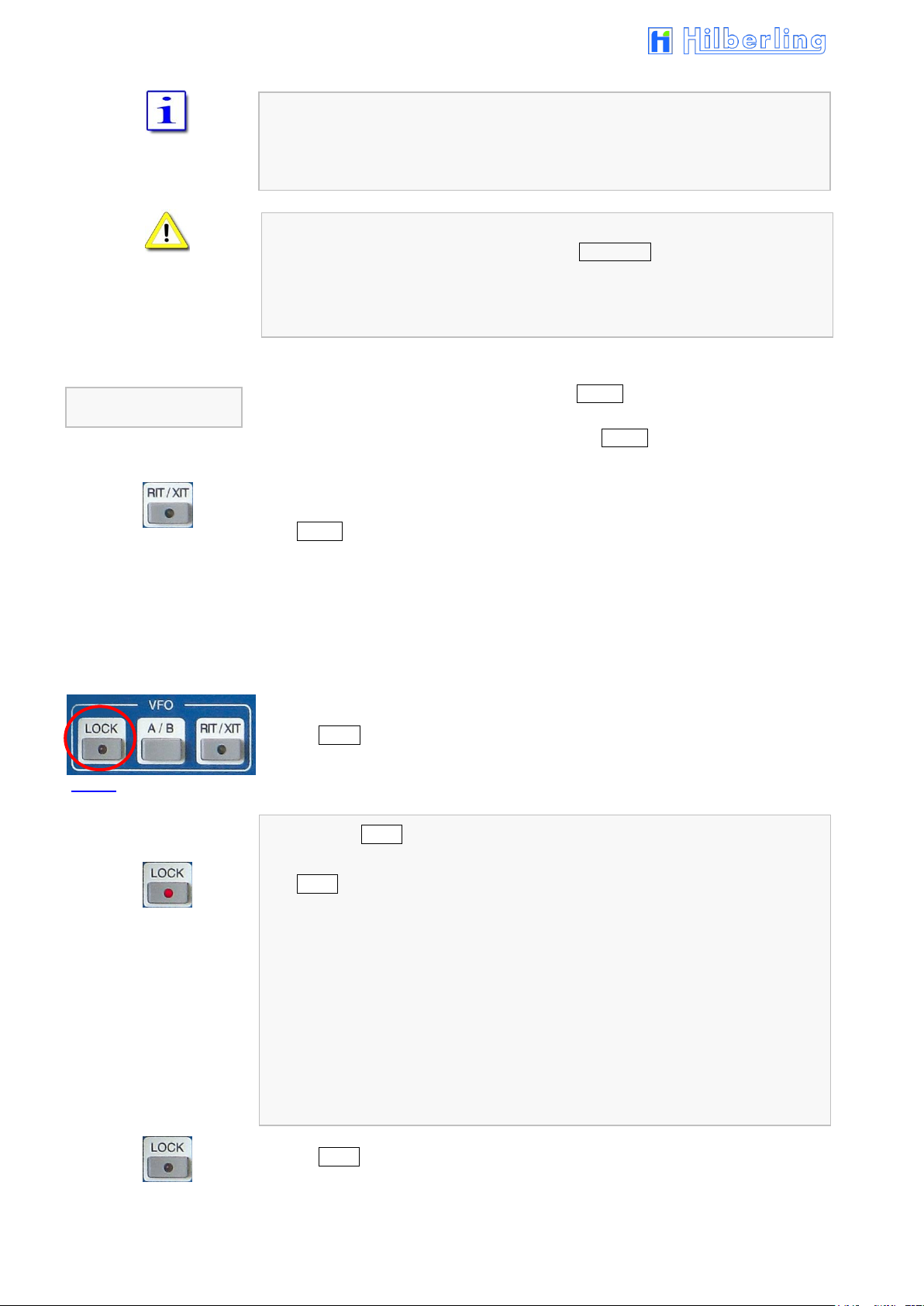
44
Termination of
RIT/XIT Operation
Fig. 57
The tuning range of RIT/XIT amounts to ±9.999 kHz.
The tuning increments of the CLAR control is identical to the selected STEP rate for
frequency tuning of selected VFO.
RIT/XIT are not available for SUB-RX.
In case the SUB-RX is the active one (pushbutton MAIN/SUB) RIT/XIT and the offset are
no longer displayed for the MAIN-RX which now operates in background.
Changing MODE will always terminate RIT/XIT operation.
If the RIT/XIT softkey menu is displayed, pushing RIT/XIT will terminate this mode and
the VFO menu will be called up.
If the RIT/XIT softkey menu is not displayed, pushing RIT/XIT will call it up and a second
push will terminate RIT/XIT operation:
VFO menu will be called up.
RIT/XIT-LED will turn off.
Display of RIT / XIT and the offset frequency will be blanked out.
11.9 Locking VFO Settings LOCK
All controls that will have an effect on the frequency selected can be locked through
pushing LOCK button which is located in the cluster VFO.
When pushing LOCK:
LOCK LED will be on.
The following controls (knobs, buttons) are locked:
MAIN-RX VFO
SUB-RX VFO
STEP-VFO
BAND
CHANNEL / MEM
RIT / XIT
MAIN / SUB
VFO A / B
Pushing LOCK again will terminate locking of controls; LED will turn off.

PT-8000A Operating Manual v2.01.10 45
Fig. 59a
Filter Bandwidth
Transceiver Frequency
DSP activated
Fig. 59b
Fig. 58
12 FILTER BANDWIDTH AND SHIFT FUNCTION FILTER WIDTH / SHIFT
Filtering in the PT-8000A is obtained in the 1st IF @ 40.7 MHz with a 6-pol. Filter and
in the 2nd IF (IF-2) @ 10.7 MHz with an "IM3 Protector" said prefilter with bandwidth
0.5 kHz, 3 kHz and 15 kHz.
Prefilters are selected automatically depending on operation mode (default filter;
manual filter selection see Pages 59 to 62)
After passing through the 16-pol. quartz filter ladder the channel selection can be
further enhanced by Digital Signal Processing (DSP) working in the audio range.
The DSP performs the following tasks:
Interpolation between analogue filter bandwidths @ 10.7 MHz.
Slope increase of the filter flanks @ 10.7 MHz and elimination of effects of group
delays by the filters.
Shift the placement of the filters (SHIFT function respective band-pass tuning).
Activating DSP filtering is accomplished by the pushbutton FILTER located in the cluster
DSP (Bandwidth and Shift/Pitch see Page 46 – 12.2).
In case the FILTER LED is off (shown in pic 58) only the analogue (Xtal-) filters are
active. The selected bandwidth is displayed and graphically expressed (see Page 46 /
12.1).
When pushing FILTER:
The DSP will be activated.
FILTER-LED will be on.
The display will indicate “DSP” operation.
WIDTH and SHIFT control located in the cluster MODE is used to adjust the filter
bandwidth and to shift the passband across the spectrum.
Pushing the knob will toggle between WIDTH and SHIFT function, turning will select the
current value.
For specific feature in CW mode see Page 23.
Depending on operation MODE there are analogue filters available which are
interpolated in bandwidth by the DSP (see Page 46).

46
LSB/USB
CW
AM
FM
LSB/USB
CW
AM
FM
* Factory hardware extension
12.1 Filter Bandwidth DSP Off
Depending on MODE the following Xtal-filters (analogue filters) and passband shifts are
available (using WIDTH and SHIFT control) when DSP is not activated:
Width 1.8 / 2.0 / 2.4 / 2.7 / 3.1 / 6.0 kHz
Shift -200 Hz ... 600 Hz in 100 Hz steps
The 3.0 and 15.0 kHz filter are the allocated IF-2 filter for SSB mode.
Width 0.5 kHz ( / 0.25 kHz with optional hardware extension *)
Shift/Pitch 400 Hz ... 1,000 Hz in 100 Hz steps
The 0.5 kHz filter is the allocated IF-2 filter for CW mode.
Width 15.0 kHz
Shift n/a
The 15.0 kHz filter is the allocated IF-2 filter for AM mode.
Width 15.0 kHz
Shift n/a
The 15.0 kHz filter is the allocated IF-2 filter for FM mode.
When Noise Blanker is active, always the 15.0 kHz filter operates.
12.2 Filter Bandwidth DSP On
Depending on MODE the following bandwidths (Xtal-filters and analogue filters) and
passband shifts are available (using WIDTH and SHIFT control) when DSP is activated:
Width
2.6 / 2.7 / 2.8 / 2.9 / 3.0 / 3.1 / 3.2 / 3.3 / 3.4 / 3.5 / 4.6 / 6.0 kHz
Shift 0 Hz ... 600 Hz in 50 Hz steps
Width 50 / 100 / 200 / 400 / 500 Hz
Shift/Pitch 400 … 1,000 Hz in 50 Hz steps
Width
Shift n/a
Width
Shift n/a
For FM the “bandwidth” is related to the audio response only; RF-bandwidth remains
always 15.0 kHz.
When Noise Blanker is active, always the 15.0 kHz filter operates.
1.0 / 1.2 / 1.4 / 1.6 / 1.8 / 1.9 / 2.0 / 2.1 / 2.2 / 2.3 / 2.4 / 2.5
The 3.0 and 15.0 kHz filter are the allocated IF-2 filter for SSB mode.
The 0.5 kHz filter is the allocated IF-2 filter for CW mode.
2.4 / 2.5 / 2.6 / 2.7 / 2.8 / 2.9 / 3.0 / 3.1 / 3.2 / 3.3 / 3.4 / 3.5
4.6 / 6.0 kHz
The 15.0 kHz filter is the allocated IF-2 filter for AM mode.
2.4 / 2.5 / 2.6 / 2.7 / 2.8 / 2.9 / 3.0 / 3.1 / 3.2 / 3.3 / 3.4 / 3.5
4.6 / 6.0 kHz
The 15.0 kHz filter is the allocated IF-2 filter for FM mode.

PT-8000A Operating Manual v2.01.10 47
Fig. 60
Fig. 61
Fig. 63
Fig. 62
13 NOTCH FUNCTIONS / NOISE REDUCTION / NOISE BLANKER
13.1 Notch Filter: IF-Notch and DSP Multi Notch
Two notch filters of different type are available in the PT-8000A.
One is working at 2nd IF @ 10.7 MHz – it´s the classical type of manual notch filtering
using a Xtal bridge – the IF-NOTCH.
The other one is part of the DSP – it´s an Automatic Multi-Notch Filter (ANF/MNF) –
here called the DSP NOTCH.
IF-NOTCH and DSP-NOTCH may be engaged simultaneously.
Notch filtering is not available in AM and FM. In case NOTCH filtering is active and
operation mode is changed to AM/FM, both NOTCH filters will cease operation.
After power on both NOTCH filters are off.
13.1.1 IF-NOTCH Filter
The IF-NOTCH will be
activated by pushing
the control IF-NOTCH
which is located as
depicted:
On display, IF NOTCH is outlined as NOTCH 2.
Turning IF-NOTCH will adjust the variable notch through the passband hence the
interference will be almost nullified.
13.1.2 DSP Multi NOTCH Filter („digital“ MNF)
Pushing button NOTCH located in the
cluster DSP will activate the automatic multinotch filtering (ANF/MNF):
On display, DSP NOTCH is outlined as NOTCH 1.
DSP NOTCH-LED will be on.
The DSP will now detect even multiple interferences and will cancel them effectively.

48
Fig. 64
Fig. 66
Fig. 67
Fig. 65
13.2 DSP Noise Reduction NR
Pushing button NR located in the cluster
DSP will activate the Automatic Noise
Reduction (ANR or short NR):
On display, DSP NR is outlined as NR.
DSP NR-LED will be on.
NR is off after power on.
13.3 Noise Blanker NB
The Noise Blanker will
be activated by pushing
control RX-NB which is
located as depicted:
On display, RX-NB it is outlined as NB.
Turning control RX-NB will adjust the threshold of the noise blanker to the specific
situation. Noise is dramatically reduced hence improving the readability of weak
signals.
NB is off after power on.

PT-8000A Operating Manual v2.01.10 49
Fig. 69
Fig. 68
14 SQUELCH SQL
The SQUELCH (SQ) is activated by default and will be affected
by the control SQL which is located as depicted.
The threshold for squelch operation is adjusted by turning the
knob.
Once the SQL is activated and the threshold has engaged i.e.
the RX is silent, push and hold the SQL to override the threshold
momentarily.
To deactivate squelch function permanently turn knob SQL fully counter-clockwise.
A triangle ("") is moving in the S-meter (active RX only) according to the threshold
setting of the SQL control.
Squelch function is not possible in any operation mode if AGC is deselected and
manual gain control is engaged (see Page 51).

50
AGC menu
Fig. 70
Fig. 71
Fig. 72a
15 RX GAIN CONTROL AGC / RF-GAIN
15.1 Automatic Gain Control AGC
The AGC (Automatic Gain Control) is active after power on. Its fall time of control
voltage (hang time) is set to 1 second by factory setting and can be modified using the
AGC menu. When PT-8000A is powered off the modified hang time is stored.
Deselect AGC by pushing knob RF (see bottom and Page 51)
Pushing button AGC located in the cluster FUNCTION will call up the AGC menu:
Select AGC hang time 3 s; the softkey will be displayed inverse.
Select AGC hang time 2 s; the softkey will be displayed inverse.
Select AGC hang time 1 s (default value); the softkey will be displayed inverse (as
shown here).
Select AGC hang time 500 ms; the softkey will be displayed inverse.
Select AGC hang time 100 ms; the softkey will be displayed inverse.
When pushing AGC the LED will not turn on! It is only switched on when AGC is
deselected by pushing knob RF (see next Page).
To prevent missing of weak signals during tuning the MAIN- or SUB-RX the AGC hang
time will be set to 100 ms automatically.
Turn knob RF GAIN to define the threshold of AGC control
voltage. Pushing the knob will switch off AGC (see Manual
Gain Control, next page).
The adjusted threshold will be depicted by the RF GAIN Marker on S-Meter.

PT-8000A Operating Manual v2.01.10 51
Fig. 72b
Receiver
Control Voltage
AGC OFF
Receiver
Control Voltage
AGC ON
15.2 Manual Gain Control RF-GAIN
Pushing the control knob RF (RF-GAIN) allows switching from
AGC operation to manual gain control. Turning the knob will
set receiver control voltage to a constant value.
Full control range of the receiver is adjustable from 0 to 128
dB.
The RF GAIN Marker on S-Meter will depict the adjusted threshold.
Pushing knob RF:
Automatic Gain Control will be terminated.
AGC-LED located in the cluster FUNCTION will be on.
S-Meter will fall back to adjusted receiver control voltage.
Caution: In case a signal is present, the audio volume may exceed the comfort level.
Turning knob RF will adjust the receiver control voltage to a constant value, which can
be monitored by observing the S-Meter (active RX). This threshold voltage can be
raised to a certain level where a signal below is significantly less audible than a signal
above, which will not be levelled out.
The manual RF gain control allows adjusting the receiver control voltage according to
the needs in special receiving situations.
Pushing RF knob again will reactivate AGC.
Pushing AGC button alternatively will reactivate AGC as well.
AGC LED will turn off
Turning the knob RF will shift the receiver control voltage by a fixed value, which can
be monitored by observing the S-Meter (active RX). This AGC threshold can be raised
to a certain level where a signal below is significantly less audible than a signal above,
where AGC action will level out the signal.
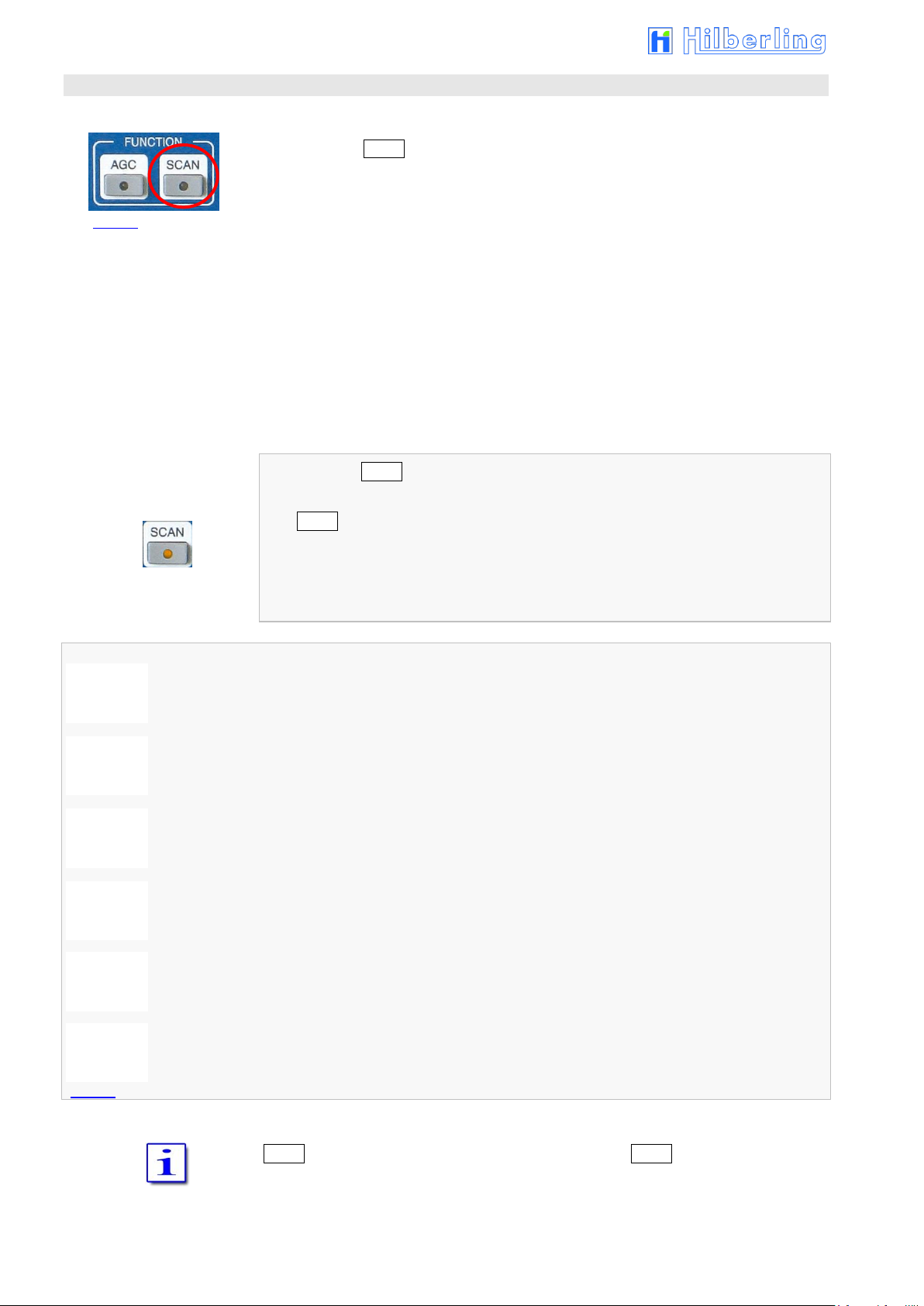
52
SCAN menu
5 s
10 s
15 s
20 s
25 s
Fig. 73
Fig. 74
16 STORAGE FREQUENCY SCANNING SCAN FUNCTION CU RRENT LY DEACTIVATED
Pushing button SCAN located in cluster FUNCTION will activate scanning of channels
which are earmarked for scanning (CHANNEL - see Page 34).
These frequencies will be checked for a signal.
The RX will scan the channels from lower to higher frequencies.
If the squelch is engaged scanning will stop when a signal on a scanned channel
opens the squelch
If the squelch is open, the RX will pause on the scanned frequency for a time
defined. After this time has elapsed the scanning will continue.
If the squelch engages during the pause scanning will continue immediately.
When pushing SCAN
SCAN-LED will be on
the frequency of the standby VFO will disappear. Instead information about the
scanned channel is displayed as in channel mode (see Page 34)
SCAN softkey menu will be called up:
Delay time is 5 seconds
Delay time is 10 seconds
Delay time is 15 seconds
Delay time is 20 seconds
Delay time is 25 seconds
Delay time is infinite
Scanning will be terminated upon activating PTT, VFO tuning, STEP-VFO or pushing
SCAN. The frequency of the standby VFO will reappear, SCAN-LED will be off.

PT-8000A Operating Manual v2.01.10 53
MENU I menu
Fig. 75
Fig. 76
17 FIRMWARE VERSIONS / CALIBRATION /
SPEAKER / DISPLAY / VOICE RECORDER MENU I
BAUD RATES CAT-INTERFACES MENU II
The button MENU located in the cluster DISPLAY provides access to show (and to
update, see appendix A2) the firmware versions, to calibrate the internal reference and
to several properties like display brightness and RX audio routing, furthermore to the
voice recorder and to the selection of baud rate of both CAT interfaces.
Pushing button MENU will call up the MENU I menu (see below).
Pushing button MENU again will call up the MENU II menu (see Page 54).
Pushing the button one more time will call up again the MENU I menu.
The SOFTWARE menu will be called up to give access to update the PT-8000A
firmware (see Appendix A2); the display will show the software versions of MAIN-, RX-,
ANT-Tuner- and Display-CPU.
The CAL menu will be called up to calibrate the internal reference (see 17.2 / P. 55).
The DIM menu will be called up to set the brightness of the display (see 17.3 / P. 56).
The VOICE REC menu will be called up to give access to recording functions
(see 17.4 / P. 57).
RX speaker allocation;
the key toggles between Audio Norm and Audio Split (see 17.1 / P. 54).

54
MENU II -Menü
Fig. 76b
Fig. 76c
Fig. 77
If a different softkey menu than MENU I is displayed, pushing twice button MENU in
the cluster DISPLAY will call up the MENU II menu:
Cyclic change of data transfer rate at USB connector (J22 / „RS232 Remote“)
9600 19200 38400* 57600 Baud
Cyclic change of data transfer rate at D-Sub „Transverter“(J21 / Pin 12 RX, Pin 24 TX)
9600 19200 38400* Baud
* Factory Setting
Make sure the parameters of the used interface of your computer (COM-Port) are the
following (Start button Control Panel System and Security System Device
Manager Ports (COM & LPT) right mouse button on e.g. xyz(COM3) Properties
Port Settings):
Bits per second (Baud): 38400 (factory setting of PT-8000A, see above;
if changed there, then change also here)
Data bits: 8
Parity: none
Stop bits: 1
Flow control: none
17.1 RX-Speaker Allocation Audio NORM / SPLIT
Audio Norm will feed audio from MAIN-RX and SUB-RX to both speakers (PT-8000A
and HN-8000).
Audio Split will separate audio from MAIN-RX and SUB-RX hence the MAINRX
signal will be fed to PT-8000A speaker and the SUB-RX signal to HN8000 speaker.
True for both settings of speaker allocation:
Turning • MAIN will adjust the volume of the MAIN-RX signal.
• SUB will adjust the volume of the SUB-RX signal.
Pushing • MAIN will turn on/off PT-8000A speaker.
• SUB will turn on/off HN-8000 speaker.

PT-8000A Operating Manual v2.01.10 55
CAL menu
REF CAL menu
Fig. 78
Fig. 79
17.2 Calibration of the Internal Reference
Pushing softkey CAL (MENU menu) will call up the Calibration menu:
Return to MENU I menu (see previous Page).
The REF CAL menu will be called up to calibrate the internal Reference (see below);
a dialog box is displayed instead of the standby VFO frequency (see Page 55 Figure
80a).
Pushing softkey Ref CAL (CAL menu) will call up Reference Calibration menu; a dialog
box is displayed instead of the standby VFO frequency (see next Page Figure 80a):
Return to CAL menu (see above).
Activating the input mask for correction value of reference oscillator;
the softkey will be displayed inverse; see next Page Figure 80b.
Storing the correction value (see next Page Figure 80d).
Setting back the correction value to zero.

56
DIM menu
Fig. 81
Fig. 80a
Fig. 80c
Fig. 80b
Fig. 80d
Fig. 80e
The dialog box for calibration of reference when pushing Ref CAL:
Pushing Ref SET will activate the input mask:
The correction value for the reference oscillator is adjustable by turning the
SUB VFO / REF SET knob. Tuning range ± 10 Hz Ref (±1 ppm).
Pushing Ref Enter will terminate the input procedure; the new value will be stored
permanently:
17.3 Brightness of Display DIM
Pushing softkey DIM (MENU menu) will call up DIM softkey menu:
Return to the MENU menu.
Lightens up the display stepwise.
Display brightness is adjustable in ten steps.
Darkens the display stepwise.
Display brightness is adjustable in ten steps.

PT-8000A Operating Manual v2.01.10 57
VOICE REC menu
Fig. 82a
Recording
Playback
Graphics Display
Fig. 82b
17.4 Audio Recording VOICE RECORDER
For audio signal recordings there are 4 recording tracks available with a capacity of
29.8 seconds each track.
Pushing softkey VOICE REC (MENU menu) will call up the VOICE REC menu;
a graphic (Figure 82b) will be displayed right next to the frequency:
Return to MENU menu.
Cyclic change of record source when pushing repeatedly.
MAIN (-RX) SUB (-RX) MIC (-TX) 0dBm (-TX) DATA (-TX)
Start and Stop of recording (toggle mode); Start and Stop will be displayed
accordingly.
Play and Stop playing (toggle mode) of all takes of the current track; Play and Stop will
be displayed accordingly.
Clear recording memory (current track only).
Loop all recordings (current track only).
The selected memory track is shown as a blue number and a yellow marker above
the track graphic; select track by turning STEP-VFO knob.
Recording position and status is shown as R> [seconds] and a blue bar in the
graphic.
Play position is shown as P> [seconds] and a red marker line in the graphic.
If one track is only partially written one or more recordings can be added.
In case the memory track has reached its capacity the recording will be ceased.
Rec Start will be displayed. However, a new record is not possible until the
memory has been cleared.
Playback will always start at the very beginning of the track.
When playback is finished (end of record or Stop) Play softkey is displayed.
The loop function may be activated during playback; the record will be repeated
endless until Stop is activated.
All Audio Signals (CW, SSTV etc.) can be recorded.
If the records are to be transmitted simply key the TX (transmit key T9; TX / ON key)
when playback is running.

58
METER menu
Fig. 83
Fig. 84
Fig. 85a
Fig. 85b
Fig. 86a
Fig. 86b
Fig. 86c
18 SCALE SELECT METER
Pushing button METER located in the cluster DISPLAY will call up the METER menu with
the following options:
1. Selection of meter display right below the S-Meter (Figure 85a/b):
Control voltage of the Automatic Level Control (ALC)
MIC compression level (COMP)
2. Selection of scale units for input signal strength (Figure 86a/b/c):
Hams radio units (S + dB)
Input power @ 50 Ohm (dBm)
Input voltage @ 50 Ohm (dBµV).
Control voltage of the ALC will be displayed (SSB mode
only);
the softkey will be displayed inverse (as shown here).
Compression level from MIC / TX will be
displayed;
the softkey will be displayed inverse.
S-Meter indicates S + dB;
softkey displayed inverse
(as shown here).
S-Meter indicates dBm;
softkey displayed inverse.
S-Meter indicates dBµV;
softkey displayed inverse.

PT-8000A Operating Manual v2.01.10 59
RX menu HF
Fig. 87
Fig. 88
19 BASIC SETTINGS RX/TX
19.1 RX Settings
19.1.1 HF: Antenna Select / Preamplifier / Preselector / Attenuator / IF-2 Filters
Pushing button RX/TX located in the cluster MODE will call up two types of menus
which gives access to various basic settings for RX and TX.
The last used menu (TX or RX) will be called up.
Depending on whether HF or VHF is selected the menus and display
described below may vary.
Pushing button RX/TX or softkey RX (TX menu) will call up the RX menu HF with
following options:
Select antenna #1 or – second press – antenna #1 for TX and an additional RX
antenna; the display will show ANT 1 or ANT 1 RX if appropriate. (see Page 14, Table
10, No. 4), the softkey will display as well (inverse as shown). See note below.
Select antenna #2 – the display will show ANT 2 if appropriate (see Page 14, Table
10, No. 4), the softkey will be displayed inverse.
Activate Preamplifier (on / off); the display will show AMP 10dB (see Page 14, Table
10, No. 1); the softkey will be displayed inverse.
*** only available 1.8 to 30 MHz ***
Activate Preselector (on / off); the display will show Preselect (see Page 14, Table 10,
No. 2); the softkey will be displayed inverse.
*** only available 1.8 to 30 MHz ***
Access to ATT/IF-2-Filter menu HF to activate the attenuator and to select a different
IF-2 filter (see next Page).
Access to TX menu (see Page 63).
Note
In case the antenna selection of MAIN- or SUB-RX will be changed from ANT 1 to ANT
1 RX (or vice versa), the other RX is also affected if it is not connected to ANT 2.
If one of both RX is connected to ANT 2, changing the antenna selection of the other
RX from ANT 1 to ANT 1 RX (or vice versa) will take no effect.

60
ATT / IF-2-Filter menu HF
Fig. 89
19.1.2 HF: Attenuator / IF-2 Filter Select
Pushing softkey ATT / IF-2 (RX menu HF) will call up ATT / IF-2-Filter menu HF:
Return to the RX menu HF (see previous Page).
Activate 10 dB Attenuator (on / off); the display will show ATT (see Page 14, Table 10,
No. 3); the softkey will be displayed inverse.
Select 15.0 kHz IF-2 filter; default filter for AM and FM mode as well as for SSB if filter
bandwidth > 3.0 kHz; the softkey will be displayed inverse.
Select 3.0 kHz IF-2 filter; default filter for SSB mode if filter bandwidth ≤ 3.0 kHz; the
softkey will be displayed inverse (as shown here).
Select 0.5 kHz IF-2 filter; default filter for CW mode;
the softkey will be displayed inverse.
If the Noise Blanker (NB) is activated the 15 kHz IF-2 filter will always be selected.
If MODE is changed the default filters will be activated immediately. Same is true for
power ON condition.

PT-8000A Operating Manual v2.01.10 61
RX menu VHF
Fig. 90
19.1.3 VHF: Preamplifier PRE AMP / DC on Antenna OUT DC AMP
Pushing button RX/TX or softkey RX (TX menu) will call up the RX menu VHF with the
following options:
Preamplifier will be activated; the display will show AMP VHF
(see Page 14, Fig. 17b and Table 10, No. 1);
the softkey will be displayed inverse.
Access to IF-2-Filter menu VHF to select a different IF-2 filter
(see next Page).
When activating this function 12 Volt DC are fed to the VHF antenna connector (J1) in
order to run remote switches or remotely operated amplifiers through this supply
voltage. The current is rated to 1 Amp;
the softkey will be displayed inverse.
Access to TX menu (see Page 63).

62
IF-2-Filter menu VHF
IF-2
Fig. 91
19.1.4 VHF: IF-2 Filter Select
Pushing softkey IF-2 (RX menu VHF) will call up IF-2-Filter menu VHF:
Return to the RX menu VHF (see previous Page).
Select 15.0 kHz IF-2 filter; default filter for AM and FM mode as well as for SSB if filter
bandwidth > 3.0 kHz; the softkey will be displayed inverse.
Select 3.0 kHz IF-2 filter; default filter for SSB mode if filter bandwidth ≤ 3.0 kHz; the
softkey will be displayed inverse (as shown here).
Select 0.5 kHz IF-2 filter; default filter for CW mode;
the softkey will be displayed inverse.
If the Noise Blanker (NB) is activated, the 15 kHz IF-2 filter will always be selected.
If MODE is changed the default filters will be activated immediately. Same is true for
power-on condition.

TX menu
Fig. 92
PT-8000A Operating Manual v2.01.10 63
19.2 TX Settings
19.2.1 Leveler TX-Audio LEV
Pushing button RX/TX or softkey TX (RX menu HF or VHF) provides access to the TX
menu, which offers the following functions:
Access to 3 band equalizer for TX (see next Page).
Activating TX Audio Leveler (on/off); the display shows LEV (above S-Meter);
the softkey will be displayed inverse.
Access to KEYER menu (see Page 65).
Access to TX filter / TX shift menu (see Page 66).
Access to TX OUT menu (see Page 67).
Access to RX menu HF (Page 59) respectively VHF (Page 61).

64
EQUALIZER menu
EQ Band 1
EQ Band 2
EQ Band 3
0 ... 500 Hz
500 ... 1500 Hz
1500 ... 3000 Hz
Tab. 17
Fig. 94
1 2 3
EQU bands
Fig. 93a
1 2 3
EQU bands
Fig. 93b
19.2.2 Equalizer Operation TX-Audio EQ
To control the sound of TX audio signals the PT-8000A provides a 3 band equalizer
featuring the following frequency bands:
When pushing softkey EQ (on TX menu, see previous page):
The display will show the EQ graphics in status “Off” in the upper left corner
instead of filter adjustments.
Cursors representing the values of the three bands are set to “0”;
the equalizer is inactive (yet).
EQUALIZER menu will be called up:
Return to TX menu (see previous Page).
Increase gain of selected EQ band in 1dB steps. Maximum gain is +9dB
(adjustable only when EQ is activated).
Select EQ band in a cyclic manner (see Table 17 on top; here shown: Band 1).
Band 1 Band 2 Band 3
Decrease gain of selected EQ band in 1dB steps. Maximum gain is -9dB
(adjustable only when EQ is activated).
Reset all previous settings to 0 dB for all 3 EQ bands
(only possible if EQ is activated).
Activating the Equalizer (on/off); the display will show EQ (above S-Meter);
the softkey will be displayed inverse.
The frequency band adjustments can be edited.
When pushing softkey EQ (on this EQUALIZER menu):
The equalizer will be activated; the softkey will be displayed inverse;
the frequency band adjustments will take effect and can be edited
The display will show the current EQ settings in the upper left corner.
The selected band cursor is blue colored; its value in dB for increase/decrease will
be displayed next to it.
The display will show EQ (above S-Meter)

PT-8000A Operating Manual v2.01.10 65
KEYER menu
Fig. 95
Adjustment of EQ bands is also possible with WIDTH/SHIFT control (as long as the
EQUALIZER menu will be displayed and EQ is activated):
Pushing will select one of the three EQ bands in a cyclic manner.
Band 1 Band 2 Band 3
Turning will adjust the value of increase/decrease.
Settings only will take effect when equalizer has been activated by softkey EQ
(EQUALIZER menu, see Figure 94).
The EQ graphics will only be shown as long as the EQUALIZER menu will also be
displayed.
19.2.3 Keyer Select
Pushing softkey Keyer (TX menu) will call up the KEYER menu:
Return to TX menu (see Page 63).
Select one of the following modes of the internal keyer in a cyclic manner:
Iambic Mode A Iambic Mode B Ultimatic
The respective softkey will be displayed inverse (as shown here).
Select Normal mode of internal keyer;
the softkey will be displayed inverse.
Reverses paddle function to accommodate left-/right hand operation (on/off);
the softkey will be displayed inverse.
Shuts off internal keyer to allow use of external keying device;
the softkey will be displayed inverse.
See also:
TX-DELAY – Adjust the time for transmit⇨receive switching for CW mode: Page 71
KEY SPEED – Adjust CW keying speed of the internal keyer: Page 71.

66
TX-Filter / TX-Shift menu
Fig. 96
19.2.4 TX Filter Select / TX Shift Select
Pushing softkey TX-Fi / TX-Sh (TX menu) will call up the TX-Filter TX-Shift menu:
Return to TX menu (see Page 63).
Select TX filter bandwidth; softkey t will be displayed inverse for
4 seconds; along the way turn STEP-VFO knob to select new value; after
a period of 4 seconds without any activity or when pushing the knob
selecting mode will be terminated.
Select TX passband shifting: The Softkey will be displayed inverse for 4
seconds; along the way turn STEP-VFO knob to select new value; after a
period of 4 seconds without any activity or when pushing the knob
selecting mode will be terminated.
Turning STEP-VFO/MEM/CH knob will allow the following:
Filter – Select TX filter bandwidth.
Tuning range: 2.2 ... 3.4 kHz
Increments: 0.1 kHz
Shift – Select TX passband shifting.
Tuning range: 0 ... 300 Hz
Increments: 25 Hz
Pushing knob STEP-VFO/MEM/CH or a period of 4 seconds without any activity will
terminate selecting mode.

PT-8000A Operating Manual v2.01.10 67
TX OUT menu
Fig. 97
19.2.5 TX Signal Settings
Pushing softkey TX-OUT (TX menu) will call up the TX OUT menu:
Return to TX menu (see Page 63)
TX signal will be routed to the internal power amplifier; the display will show the 10 W
or 250/100 W (HF/VHF) Power Meter Scale (see Page 70 , Fig. 104b/c/d);
the softkey will be displayed inverse (as shown here) <default>.
Additional delay of the RF signal in relation to the PTT signal between
0 ms and 50 ms with 5 ms steps; pushing Delay (the softkey will be
displayed inverse) and turn STEP-VFO knob; input mode will
deactivate after 5 seconds of inactivity.
Activation “Wait for External Device”: The PT-8000A sends out no RF signal unless an
enable signal (e.g. from an external PA) is present at J17 pin 9.
TX signal will be routed to socket TX ext. +20dBm (J14; BNC; rear panel) to drive
external equipment (power amplifier, transverter). The internal power amplifier will be
shut down; the display will show the 100mW Power Meter Scale (see Page 70 ;
Fig. 104e); the softkey will be displayed inverse.
Adjustment the Impedance (Microphone socket Pin 1/5+7) to low-ohmic (600 Ω @
1 kHz (Hilberling T9); the Softkey will be displayed inverse [as shown here] <default<)
and high-ohmic microphones (up to 50 kΩ @ 1 kHz).

68
Fig. 98
Fig. 99
Fig. 100a
Fig. 100b
Fig. 100c
20 TRANSMITTER CONTROLS
Various controls for transmitter settings are located on the front panel as depicted.
Transmitting (TX) is only possible when MAIN-RX is the active one and SUB-RX is
working in the background.
20.1 Antenna Tuner ANT-TUNER
20.1.1 Activate TUNER
For protecting the power amplifier the output power will be reduced if SWR is greater
than 1.5. Up to SWR close to 2.0 the internal antenna tuner enables to increase the
antenna adjustment (see also Page 3)
Pushing TUNER button will activate the antenna tuner.
TUNER-LED will be on.
20.1.2 Start Re-Tuning Cycle START
Pushing button START will start the detection and storage for optimal adjustment of the
antenna tuner at the current frequency. The output power is reduced to driver power.
START-LED will be on.
The antenna tuner starts its automatic alignment and will terminate automatically.
START-LED will be off.
20.1.3 Permanent Transmit Operation TX / ON
Pushing button TX/ON will switch PTT permanently.
E.g. when antenna tuner has been adjusted (20.1.1 and 20.1.2) the output power can
be checked.
Pushing TX/ON will activate TX operation.
TX-LED will be on.
Pushing TX/ON again will terminate TX operation.
MAIN-RX LED will be on.

PT-8000A Operating Manual v2.01.10 69
Fig. 102
Fig. 101
Fig. 103
20.2 ZERO-BEAT
Push and hold knob ZERO-BEAT will activate a 440 Hz sinus
tone in RX and TX mode, in FM mode there is a 1750 Hz sinus
tone.
In RX mode the tone will be heard in both RX. The volume might
be adjusted by turning the knob.
In TX mode the tone will be transmitted with microphone signal.
Given both transmitting and receiving stations can activate a 440 Hz tone, an
interference might be heard in case both station vary in RX and/or TX frequencies.
20.3 Microphone Sensitivity MIC (Gain)
Turning knob MIC (Gain) will adjust microphone sensitivity.
When operating by microphone Hilberling T9 and in normal
mode of speaking the knob should be adjusted between
position clock 9 and clock 12.
The correct modulation can be monitored on the ALC display (see Page 58, SSB mode
only). If the yellow or red range is shown, the microphone sensitivity should be
reduced.
For preadjustment of microphone sensitivity see Page 17 , Fig. 20.
ALC display is only available in USB/LSB mode.
Pushing the knob will (de-)activate VOX functions (see next Page).
20.4 Compression TX Audio PROC
Pushing knob PROC will turn on and off microphone processor.
Turning the knob will increase the processor level (compression
level).
Adjust not to exceed COMP limits shown on the COMP-meter (s. P. 58).
If PROC is active PROC will be displayed (above S-Meter).
PROC is only available in USB/LSB mode.

70
Fig. 104a
Fig. 104b
Fig. 104c
Fig. 104e
Fig. 106
Fig. 105
Fig. 104d
20.5 Transmit Power Control TX-PWR
Pushing the TX-PWR control will toggle the transmitter between
low- (driver power 10 Watt) and high power (PA 200 Watt HF /
100 Watt VHF).
Turning the knob allows to adjust the power continuously between 10 mW and
10 Watt respectively 1 Watt and 200/100 Watt (HF/VHF).
Power is displayed in W
The Power Meter is accordingly scaled:
Driver Power 10 W
PA Power 200 W (HF)
PA Power 100 W (VHF)
If the internal PA is deactivated for use an external one, (TX EXT is selected on TX OUT
menu, Page 67), the scale below is always shown:
TX EXT Power 100 mW
PEP
.
20.6 VOX Operation
20.6.1 VOX Threshold
Pushing the knob MIC will activate VOX („Voice Operated TX”)
operation.
Voice operated transmission enables switching PTT without
pushing TX button on microphone T9 nor button TX/ON.
To the left of the display, above operation mode indicator, VOX will be displayed.
Turning the knob MIC will affect the microphone gain (MIC-Gain; see previous Page).
If VOX has been turned on this control adjusts the trigger level
for VOX activation. Adjust sensitivity to your convenience and
speech habits.
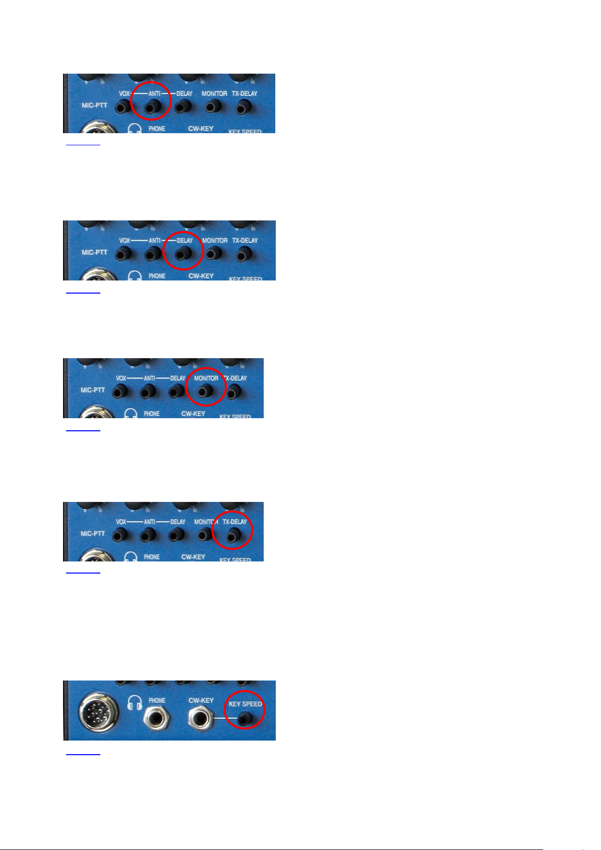
PT-8000A Operating Manual v2.01.10 71
Fig. 110
Fig. 111
Fig. 108
Fig. 109
Fig. 107
20.6.2 ANTI-TRIP VOX
Signals from the speaker(s) might trigger or trip the VOX
unintentionally. VOX ANTI-TRIP will counteract this. Adjust to
get both reliable action and anti-trip of VOX circuit.
20.6.3 Hold Time VOX DELAY
DELAY of VOX circuit allows adjusting the hold time of VOX
activation hence to get smooth VOX operation and to
counteract any VOX switching between fluently spoken voice.
20.7 Monitoring TX Signal MONITOR
20.8 Fall Time TX on CW TX-DELAY
Turning TX-DELAY clockwise will increase the turn-around which allows alignment to
individual CW habits.
TX⇨RX turn-around time: about 15 ms … 2 s.
Turning the MONITOR control will adjust the volume of the
audio to monitor the transmission of PT-8000A (avoiding
acoustic feedback). Setting control fully counter-clockwise for
terminate MONITOR function.
Turning TX-DELAY will affect the time for transmit-receive
switching (turn-around time) on CW mode. Setting TX-Delay
fully counter-clockwise ensures the shortest possible T/R turnaround – called BK (break in).
20.9 Keying Speed CW KEY SPEED
Turning KEY SPEED controls the speed of the internal keyer
(Normal mode / Iambic keyer mode A and B / Ultimatic mode;
see Page 65).
The CW weight remains constant.
CW keying speed: 5 … 60 WPM (words per minute).

72
< Blank Page >

Appendix
A1 IF Monitor Software (Windows® Program)
A2 Firmware Update and Update Software (Windows® Program)
A3 Technical Documents
A4 Customer Information
A5 Lists

< Blank Page >

PT-8000A Appendix A1 v2.01.10 A1- 1
A1 IF-MONITOR SOFTWARE
A1.1 Introduction
This appendix gives a description how to install and setup the Hilberling IF-Monitor software on your PC. Using this
software you can monitor a frequency band with a maximum range of 50 kHz (max. 25 kHz both left and right to the
PT-8000A center frequency).
Please note: Installation and use of the IF-Monitor software needs basic knowledge in handling a Windows®
computer. If you are unsure to install and setup of new programs please look for help in your personal environment
or get in touch directly to your dealer or Hilberling GmbH.
A1.2 Hardware Requirements
The IF-Monitor software will work only with a PC or laptop (the following only refers to PC) with Microsoft Windows®
operating system. Processing audio data sent by PT-8000A to the PC requires an audio input (sound card) with a
192 kHz sample rate and 24 bit resolution.
All in all is required:
1. Windows computer (administrator rights required!) featuring:
Windows XP/Vista/7/8.1/10
3 MB free disk space memory
Audio input (internal or external sound card) with a 192 kHz sample rate / 24 bit resolution
2. IF-Monitor program (will be installed on PC)
3. Audio connection cable stereo 3.5 mm phone jack
®
A1.3 Setup Software
The setup software is delivered with the PT-8000A transceiver on CD-ROM. It will
install the Hilberling IF-Monitor program on your PC.
Load the CD-ROM into the CD/DVD/BD drive.
Say on your PC this drive is allocated to the character D: the setup file can be found in
the following directory:
D:\Software\
Alternatively, the setup file first can be copied to the Windows desktop or into any
other directory on the PCs hard disk drive, e.g.:
C:\Downloads\
A1.4 Installation of the IF Monitor Program
To start the installation double-click the file
setup_PT8000_IFMonitor.exe.
On CD-ROM it can be found in the directory \Software\.
If the file was first copied to the Windows desktop or to another directory on the hard
disk, e. g. to C:\Downloads\, double-click it there.

A1- 2
Fig. A1- 2
I
II
III
The IF-Monitor program will be installed by default into the standard directory
depending on current Windows version.
A program linkage (PT8000_IF_Monitor) will be added by default to the
Windows start menu folder Start Programs PT8000_IF_Monitor.
Optional a program linkage can be created on the Windows desktop.
A1.5 Connect PT-8000A to PC by Audio Cable
For transmission of the audio data connect audio input of the PC (Line IN, 3.5 mm
stereo phone jack) to the PT-8000A (socket J15 ext. SPKR add., 3.5 mm stereo phone
jack, see Operating Manual page 5).
A1.6 Start and set up the Program
The IF-Monitor program will be started from the Windows start menu:
Start Programs PT8000_IF_Monitor PT8000_IF_Monitor
The program window will be opened to full screen size and can be minimized down to
a 800 x 600 pixel window.
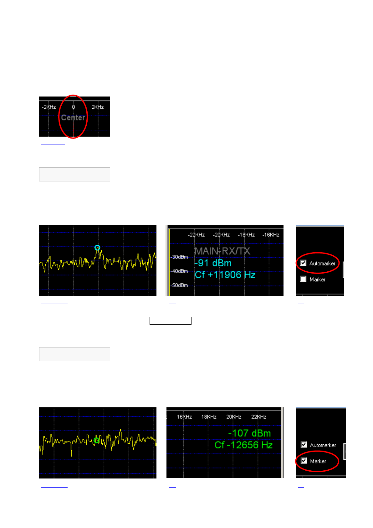
PT-8000A Appendix A1 v2.01.10 A1- 3
Automarker
Marker
Fig. A1- 4a 4b 4c
Fig. A1- 5a 5b 5c
Fig. A1- 3
A1.6.1 Program Window
The program window is structured in three areas.
In the upper area (I) options are accessible for Automarker, Marker and Peak Hold
(see chapter A1.6.2 and A1.6.3), as well as for scaling of signal level and panorama
width (see chapter A1.6.6); below, the areas are arranged for the panorama display
of MAIN-RX/TX (II) and SUB-RX (III).
A vertical red line in the middle of both display areas depicts the center frequency of
the panorama display and therefore it represents the current frequency of the PT8000A. Right of center line is shown the frequency range above the PT-8000A
frequency, left of it appropriate the frequency range below.
A1.6.2 Automarker and Marker
The Automarker (light blue circular ring) indicates the strongest signal within the
current panorama width, for each MAIN- and SUB-RX.
The strength of this signal and the frequency shifting against center frequency are
displayed in the upper left corner of the relative display area using a light blue font
(Fig. A1- 4b).
Automarker is activated each time the program was started and can be de-activated
by clicking Automarker (Fig. A1- 4c).
The Marker (light green circular ring) can be used for indication of strength and
frequency of any desired signal in the panorama.
The strength of this signal and the frequency shifting against center frequency are
displayed in the upper right corner of the relative display area using a light green font
(Fig. A1- 5b).
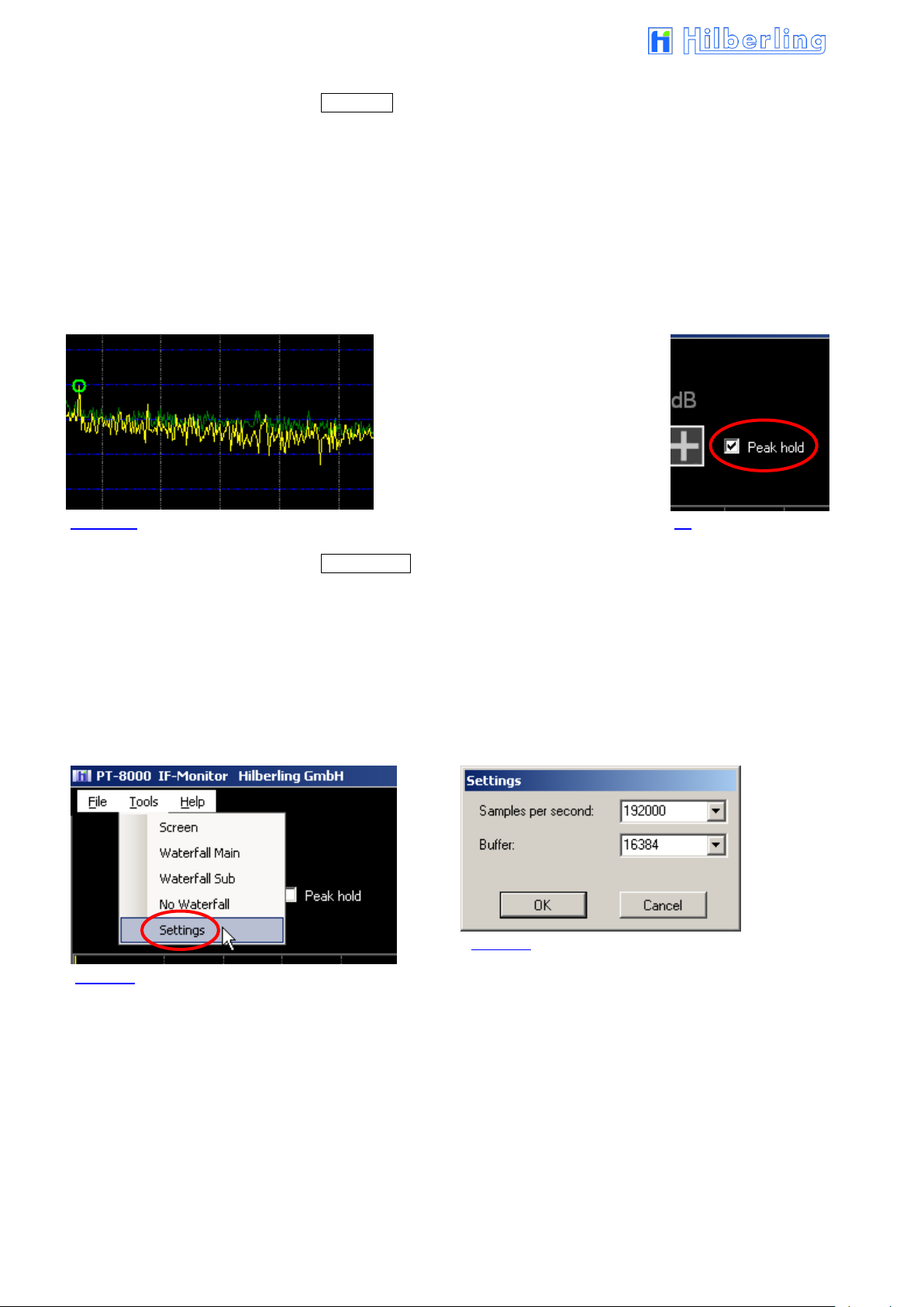
A1- 4
Fig. A1- 8
Peak curve (green)
Current curve (yellow)
Fig. A1- 6a 6b
Fig. A1- 7
Marker is deactivated each time the program was started and can be activated by
clicking Marker (Fig. A1- 5c).
When Marker is activated click into the relative display area (MAIN- (II) or SUB-RX
(III)) on a frequency shift (-line) of your choice.
A1.6.3 Peak Hold
The function Peak Hold stores the maximum value of each frequency in the panorama
over a period of three seconds and displays them as a green curve. At the end of this
period the curve will be deleted and the procedure starts from the beginning.
Peak hold is deactivated each time the program was started and can be activated by
clicking Peak hold (Fig. A1- 6b).
A1.6.4 Sample-Rate and Buffer Setup
When the program is new installed it is recommended to check the settings for sample
rate and buffer.
Click in the menu Tools the entry Settings (Fig. A1- 7).
The window Settings will be opened (Fig. A1- 8).
Samples per second: This should be 192000 (required sample rate).
If not, select this value from the drop down list.
Buffer: Interval width of frequency analysis. You may experiment with the given
values of buffer size.
Optimal depiction of the panorama curves is the goal.
For every new value click OK and check the result.

PT-8000A Appendix A1 v2.01.10 A1- 5
PC Adjustment
Fig. A1- 9
Fig. A1- 10
Fig. A1- 11
A1.6.5 Signal Level Adjustment
Because of variation in audio settings of each single computer system (PC) it is
necessary to synchronize the signal level display of IF-Monitor software and PT-8000A.
At first please check the following notes:
1. The PT-8000A is on, receives a constant signal and displays the signal strength
with the dBm scale (see chapter 18 / page 57)
2. PT-8000A and PC are proper connected according to A1.5 (page A1- 2)
3. The PC is prepared for audio signal recording (192 kHz)
If note 1 and 2 are ok, but the PT-8000A receiving signal cannot be seen in the
panorama display, check note 3.
Then proceed as follows:
Click in the Windows start menu
Start Settings
Control Panel.
The window
Control Panel
will be opened (Fig. A1- 10).
Double-click the icon
Sounds and Audio Devices.
The window
Sounds and Audio Devices Properties
will be opened (Fig. A1- 11).
Click under Audio tab
in the area Sound recording
the button
Volume...
The Recording Control panel will be opened
(Fig. A1- 12).

A1- 6
Fig. A1- 12
Fig. A1- 13
Fig. A1- 14
Make sure that sliders for
Recording, Line In and
Stereo Mix are located in
upper position and the
allocated Select boxes are
checked.
Now the PT-8000A signal
should be seen on
IF-Monitor.
If not all controls are
shown which should be
verified, open the menu
Options and click
Properties.
The window Properties
will be opened
(Fig. A1- 14).
Make sure that the boxes of Recording, Line In and Stereo
Mix are checked at least.
Click OK
Then proceed as described in Fig. A1- 12.
Close all opened windows of audio settings.

PT-8000A Appendix A1 v2.01.10 A1- 7
Fig. A1- 16
Scale move
Measured value to adjust
Move screen
Average over
Fig. A1- 15
In the IF-Monitor window open the menu
Tools
and click entry
Screen (Fig. A1- 15).
The window Screen will be opened
(Fig. A1- 16).
This window offers to you three options of settings to adjust the display of the signal
level.
Proceed as follows:
1. Use slider Scale move to shift dBm scale vertically, so that Automarkers displayed
Peak value is close to the dBm value shown on the PT-8000A display.
(Range ±50 dBm in 10 dBm steps, default value is 0)
2. Use up and down arrows or input value directly to shift the curve up and down, so
that Automarkers displayed Peak value is equal to value shown on the PT-8000A
display.
(Range ±20 dBm in 1 dBm steps, default value is 0)
3. If the curve exceeds the display range, both dBm scale and curve jointly can be
moved vertically by using up and down arrows or direct value input.
(Range ±40 dBm in 1 dBm steps, default value is 0)
This parameter allows to control the smoothing of curve. The number of measured
points which are the source of an average value can be modified by using up and
down arrows or direct value input.
(Range 0 ... 20 increment 1, default value is 3)
Click OK to terminate the adjustment.
Made changes are stored and will be used when program has been started the next
time.

A1- 8
Width [dBm]
Range from ... to ... [dBm]
140
-10 ... -150
105
-45 ... -150
70
-80 ... -150
52.5
-97.5 ... -150
42
-108 ... -150
35
-115 ... -150
Table A1- 1
Fig. A1- 17
Fig. A1- 18
Signal Level Scaling
Panorama Width Scaling
A1.6.6 Signal Level and Panorama Width Scaling
The two display areas for MAIN and SUB-RX can be scaled both vertically (signal level
/ dBm) and horizontally (panorama width / kHz).
For scaling the signal level click the buttons – and + below
Scale dB top left of the program window.
The following 6 scales are adjustable:
Default width is 140 dBm respectively -10 ... -150 dBm.
In case other ranges of scale are displayed as shown in the right column, then at least
one of the two values for Scale move and Move screen in the dialog window Screen is
unequal to 0 (see Fig. A1- 16).
For scaling the panorama width click the buttons – and +
below Span kHz top right of the program window.
There are panorama widths available of ± 25 kHz to ± 3 kHz with 1 kHz increments.
Default width is ±25 kHz.
Changes done to Scale dB and Span kHz are stored and will be used on program
restart.

PT-8000A Appendix A1 v2.01.10 A1- 9
Fig. A1- 20
I
II
III
Fig. A1- 19
A1.6.7 Waterfall Chart
For each RX a waterfall chart can be shown in addition to its panorama display. The
panorama display for the other RX will be omitted.
To view the waterfall chart of MAIN RX open the menu
Tools
and click entry
Waterfall Main.
The waterfall chart will be displayed instead of the
panorama display of SUB-RX in the lower area (III) of the
program window. It will begin to grow from the top straight
down to the maximum display range of about 35 seconds.
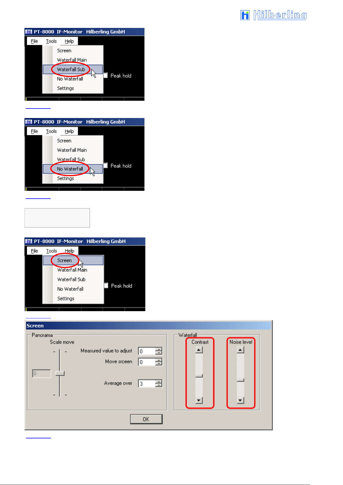
A1- 10
Color Display
Adjustment
Fig. A1- 24
Fig. A1- 21
Fig. A1- 22
Fig. A1- 23
To view the waterfall chart for the SUB RX open the menu
Tools
and click entry
Waterfall Sub.
Now the frequency panorama of the SUB-RX will be displayed
in the middle area (II), the corresponding waterfall chart in the
lower area (III).
To stop the waterfall display, open the menu
Tools
and click entry
No Waterfall.
Now both panorama displays of MAIN- and SUB-RX will be
displayed in the areas II and III of the program window.
To adjust the panorama display to make out useful signals and noise by different
colors, proceed as follows:
Open the menu
Tools
and click entry
Screen
The window Screen will be opened
(Fig. A1- 24)
Vary the settings of the sliders Waterfall contrast and Noise level, until it reaches a
good representation (useful signal light, noise dark).

PT-8000A Appendix A2 v2.01.10 A2- 1
A2 FIRMWARE UPDATE AND UPDATE SOFTWARE
A2.1 Preliminary Note
This appendix describes how to update the operation software of your PT-8000A transceiver (= firmware update).
Please note: Update of the PT-8000A operation software needs basic knowledge in handling a Windows® computer.
If you are unsure to install and set-up programs on your computer please look for help in your personal environment
or get in touch directly to your dealer or Hilberling GmbH.
A2.2 Introduction
The PT-8000A is controlled by 5 microprocessors. Therefore, a plurality of functions is defined by software. This has
clear advantages: The insertion of new features and changes in performances are possible as well as the realization
of special needs, especially for commercial applications. The update is done with a PC / laptop (hereafter referred
only to the PC) running the operating system Microsoft Windows®.
A2.3 Requirements and Procedure
To update the PT-8000A operation programs (= firmware) are required:
1. Windows computer (Administrator rights are required!) featuring:
Windows XP/Vista/7/8.1/10
14 MB free memory space on hard disk drive
USB connector
2. Update program (will be installed on PC).
3. PT-8000A operation program (firmware) in the latest version (will be transferred by the update program to
the PT-8000A); updatable is the firmware of the following microprocessors (CPUs):
MAIN-CPU
RX-CPU
ANT-Tuner-CPU
4. USB data cable (USB-A ⬄ USB-B, see Operating Manual Page 10 / Fig. 12)
For the entire update procedure we recommend the following execution, which is also reflected in the following
chapter sequence:
Preparation:
A2.4 Download the operation program(s) / the update program from the Internet
A2.5 Install the update program
A2.6 Connect the PT-8000A to the PC by USB data cable
Execution:
A2.7 Start and setup the update program
A2.8 Get PT-8000A ready to update
A2.9 Update of the MAIN-CPU or
A2.10 Update of the RX- and the ANT-Tuner-CPU
®

A2- 2
A2.4 Setup Software and Firmware
The setup software is delivered with the PT-8000A transceiver on CD-ROM. It will
install the Hilberling update program on your PC.
Load the CD-ROM into the CD/DVD/BD drive.
Say on your PC this drive is allocated to the character D: the setup file can be found in
the following directory:
D:\Software\
Alternatively, the setup file first can be copied to the Windows desktop or into any
other directory on the PCs hard disk drive, e.g.:
C:\Downloads\
Do the same with the new PT-8000A firmware. If you get it on CD-ROM it is located
in the directory
D:\Firmware\
If the firmware exists as a compressed archive file (ZIP file) it must be unpacked before
further use.
A2.5 Install Update Program on PC
To start the installation double-click the file
setup_PT8000_Update.exe.
On CD-ROM it can be found in the directory \Software\.
If the file was first copied to the Windows desktop or to another directory on the hard
disk, e. g. to C:\Downloads\, double-click it there.
The update program will be installed by default into the standard directory
depending on current Windows version.
A program linkage (PT8000_Update) will be added by default to the Windows
start menu folder Start Programs PT8000_Update.
Optional a program linkage can be created on the Windows desktop.
A2.6 Connect PT-8000A to PC by USB Data Cable
To update the software (see the following chapter A2.7) connect the PC (any USB
connector; Type A) and the PT-8000A (connector J22, Type B, see Operating Manual
Page 5) using the included USB data cable.

PT-8000A Appendix A2 v2.01.10 A2- 3
Fig. A2- 2
Fig. A2- 4
Fig. A2- 5
Fig. A2- 6
Fig. A2- 3
A2.7 Start and set up the Update Program
The update program will be started from the Windows Start menu:
Start Programs PT8000 Update Start PT8000 Update
First the program checks whether the PC's internal serial port COM 1 is available and
not already in use elsewhere.
If COM 1 is available the update program will be connected automatically and a
message box will be displayed (Fig. A2- 2).
Click OK to close the message box; the program's main window will be opened
( continue with chapter A2.7.2 Select Firmware).
If COM1 is currently not available on the PC because another application already
has access to it, an appropriate error message will be displayed (Fig. A2- 3).
Now it is necessary to set the COM port manually (see the following chapter
A2.7.1).
A2.7.1 Manual COM Port Setting
After clicking OK in the error message box (Fig. A2- 3), the Set COM port
window (Fig. A2- 4) will be opened to select a different COM port (in the
background the main program window already will be displayed).
It is advisable now to proceed in ascending order, i.e. next, select COM
port 2 by clicking COM 2.
If there appears a message box similar to Fig. A2- 2, then COM Port 2 is
connected. Click OK to close both this box and the Set COM port window
( continue with chapter A2.7.2 Select Firmware).
However, if there appears a message box similar to Fig. A2- 3 (error
message), then next, select COM port 3, etc.
If no unconnected COM port can be found, close the Set COM port
window (Fig. A2- 4) by clicking Close.
The program's main window will open (Fig. A2- 7). The large button in the
middle of the main window labeled NO COM PORT (Fig. A2- 5) indicates the
missing link.
In this case stop the update program (click Exit) and all other applications
running on the PC.
Then restart the update program and try again as described above to get a COM port
connection.

A2- 4
Fig. A2- 9
Fig. A2- 11
Fig. A2- 7
Fig. A2- 10
Fig. A2- 8
A2.7.2 Select Firmware
If COM port 1
(or another port) is
available, the program's
main window will open
with a corresponding
entry in the large
middle button. (If a
different COM port is to
be used, click the
button).
The entry No file in the field Update File indicates that no operation program has been
selected yet:
Use the Browse button to navigate to the directory where you have stored the new
operation program(s) (firmware) received from Hilberling GmbH, e.g. C:\Downloads\.
Select from the dialog box Open the new operation program
(in this example, the operation program for the MAIN-CPU /
Europe in the Downloads directory) and then click Open.
Now the selected new operation program will be displayed in the field Update File, the
version number in the field Ver.:
The field Data Length displays the file size in bytes of the operation program.

PT-8000A Appendix A2 v2.01.10 A2- 5
Fig. A2- 12
Fig. A2- 14
Fig. A2- 15
Fig. A2- 13
Tab. A2- 1
No operation program
Terminate update program
The Start button is now set to active (black font) and thus the update
program is ready for program transfer
( continue with chapter A2.8 Get PT-8000A ready to update).
If in the Open dialog box no program will be selected (by clicking Cancel), the
following message will be displayed:
In this case the Start button remains inactive (grey font).
Using the Exit button the update program may be terminated at any time.
Each PT-8000A CPU is updated separately. The filename gives a hint to the CPU, as
well as the version number:
CPU File Name Version
MAIN CPU PT8_MAIN_0137 04 Europa.H86 M 01.37 04
RX CPU PT8_RX_0118.hex R 01.18
ANT-Tuner CPU HFKoppler_V112.hex K 01.12
A2.8 Get PT-8000A ready to update
Once the PC is ready for update, now the PT-8000A needs to be set to the update
standby mode.
1. Pushing MENU button located in the cluster DISPLAY:
The MENU menu will be displayed (see Manual Page 53).
2. Pushing Soft softkey:
The SOFTWARE menu will be called up (Fig. A2- 16).
An overview of the currently loaded software versions will be shown on
display (Fig. A2- 17).

A2- 6
Fig. A2- 16
Fig. A2- 17
CPU selection
Return to MENU menu (see Manual Page 53).
Select MAIN-CPU for Update, see A2.9.
Select RX-CPU for Update, see A2.10.
Select ANT-Tuner-CPU for Update, see A2.10.
The screen Software Version PT-8000A with a list of the currently
loaded software versions will be shown on the main display area.
An update of the DISPLAY software is currently not required.
Select from the Software menu (Figure A2-16 resp. 17) the one CPU of which new
operation program you have selected in Chapter A2.7.2 to the PC program.
Depending on CPU selection the update process will be slightly different:
The update of the MAIN-CPU is described in the following chapter A2.9.
The update of the RX- and the ANT-Tuner-CPU is described in the after next
chapter A2.10

PT-8000A Appendix A2 v2.01.10 A2- 7
Fig. A2- 18
Fig. A2- 19
Fig. A2- 20
Error Messages
A2.9 Update of MAIN-CPU
Pushing MAIN Update softkey (SOFTWARE menu; Fig. A2- 16 resp. 17) will start the
update process for the MAIN-CPU.
The display will show the Bootloader screen with a prompt to start
the update program on connected PC.
If the update procedure should not be further
continued at this point, the PT-8000A is set back to
the normal mode by turning off (POWER) and restart
(after a wait of about 10 seconds).
The PT-8000A is now ready to update and the program transfer can begin.
Requirements for a successful program transfer are:
1. PT-8000A and PC are connected via USB cable (A2.6).
2. The update program has been started, a COM port is connected and the new
operation program (update file) is loaded (A2.7).
3. The PT-8000A is ready to update (A2.8).
4. The Update standby mode of the PT-8000A and the loaded operating program
agree respecting the CPU (MAIN-CPU).
Click the Start button in the main window of the update program.
The adjacent message box prompts you to set the PT-8000A ready to
update.
This is already done here, so click OK (Otherwise please catch up
before clicking, see chapter A2.8).
If a connection error is occurred (e.g. PT-8000A is not ready to update), the
adjacent message box will be shown (Fig. A2- 20).
Check the correct connection of PT-8000A and PC (by the supplied USB data cable).

A2- 8
Comparing Version
Numbers
Fig. A2- 21
Fig. A2- 22
Fig. A2- 23
Fig. A2- 24
Fig. A2- 25
Warning Notice
Does the new operation program loaded in the PC not match to the selected CPU of
the PT-8000A, this is pointed out with an error message box (Fig. A2- 21).
Note that the selected CPU of the PT-8000A matches to the operation program
loaded in the PC’s update program (letters M, R and K are prefixed to the version
number).
Now the update program compares the version numbers of the current and the new
operation program. Depending on the outcome different messages are shown on the
PT-8000A display and PC message boxes.
In case the new operation program has a higher version number than
the current version on PT-8000A, the display will show these numbers
in the lower area.
On PC screen a message box prompts you to start the program transfer.
Click OK to start the program transfer.
In case the new operation program has the same version number
as the current version on PT-8000A, the display will show a
warning notice and in the lower area these (identical) numbers.
If the update procedure should not be further
continued at this point, the PT-8000A is set back to
the normal mode by turning off (POWER) and restart
(after a wait of about 10 seconds).
On PC screen a message box will show a warning notice that the new
program version number is identical to the current version.
The message box prompts you to start or abort the program transfer.
Click OK to start the program transfer.
By clicking Cancel the program transfer will not be performed.
 Loading...