

Page 1
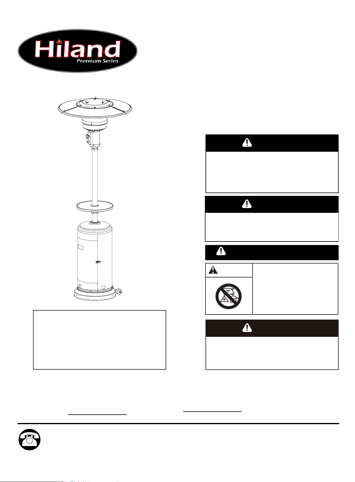
OWNER’S MANUAL
PATIO HEATER
MODEL # HLDS01
Français p. 22
p. 43
DANGER
FOR YOUR SAFETY
If you smell gas:
1. Shut off gas to the appliance.
2. Extinguish any open flame.
3. If odor continues, keep away from the appliance and
immediately call you gas supplier or fire department.
WARNING
Do not store or use gasoline or other flammable vapors
and liquids in the vicinity of this or any other appliance.
An LP-cylinder not connected for use shall not be
stored in the vicinity of this or any other appliance.
WARNING: For Outdoor Use Only
Precaution!
The Powder Coating paint process has become the most
common widely used application in the outdoor furniture
category. Unfortunately powder coating is extremely
sensitive to Humidity and Moisture. A simple process to
protect your furniture, especially flat surfaces is to apply a
simple coat of good quality car wax prior to using. If this
process is done every few months it will protect your
furniture for years to come.
DANGER
Improper installation, adjustment, alteration, service or
maintenance can cause property damage, injury or death.
Read the installation, operation and maintenance
instructions thoroughly before installing or servicing this
equipment.
CARBON MONOXIDE HAZARD
This appliance can produce
carbon monoxide which has
no odor. Using it in an enclosed
space can kill you. Never use this
appliance in an enclosed space
such as a camper, tent, car or home.
WARNING
ANS Z83.26-2014 • CSA 2.37-2014 Gas-Fired Outdoor Infrared Patio Heaters
ATTACH YOUR RECEIPT HERE
Serial Number
Questions, problems, missing parts? Before returning to your retailer, call our customer
service department at 1-888-775-1330, 7 a.m. - 4 p.m., PST, Monday - Friday.
Purchase Date
1
WH16/01
Page 2
PACKAGE CONTENTS
A
B
C
D
E
F
G
H
I
A
B
C
D
J
E
F
G
K
H
I
J
L
K
L
M
M
N
N
O
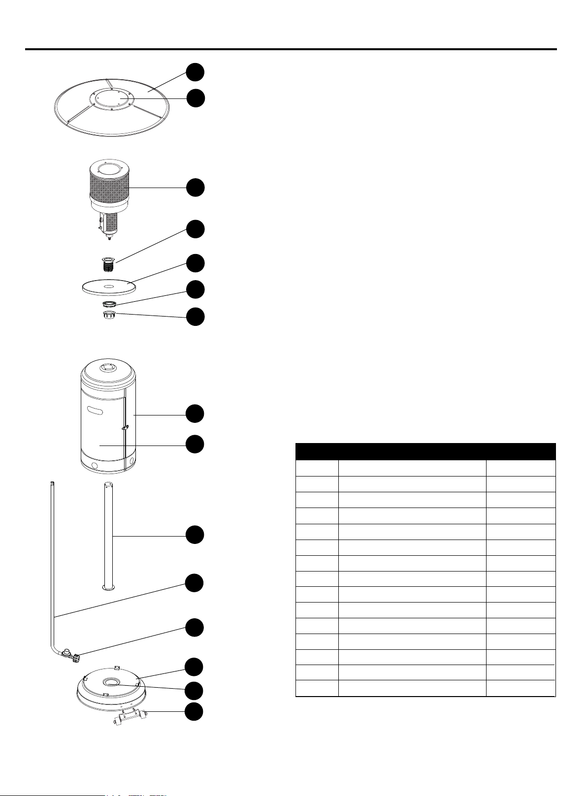
Reflector Panel
Reflector Plate
Head Assembly
Screw Coupler
Table
Tightening Spacer
Fastening Nut
Cylinder Housing
Door (preassembled)
Post
Gas Hose
Regulator
Base
Bucket (preassembled)
Wheel Kit
NOITPIRCSED TRAP QUANTITY
3
1
1
1
1
1
1
1
1
1
1
1
1
1
1
O
2
Page 3
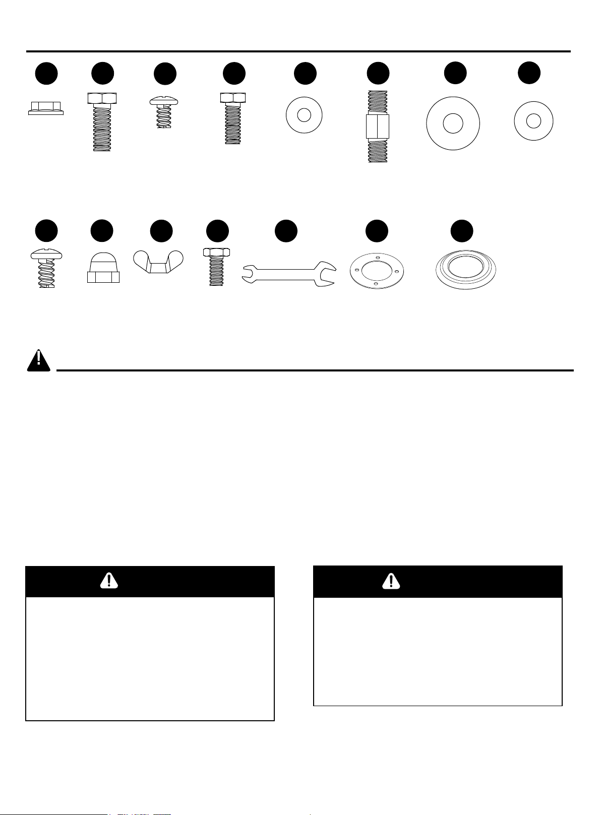
HARDWARE CONTENTS (shown actual size)
DANGER
AA
M8
Flange
Nut
Qty. 2
II
M6 x 10 mm
Screw
Qty. 9
SAFETY INFORMATION
BB
M8 x 16 mm
Bolt
Qty. 2
JJ
Cap Nut
Qty. 9
CC
M5 x 8 mm
Screw
Qty. 4
KK LL MM
Wing Nut
Qty. 3
Stainless
Steel Bolt
Qty. 4
DD EE
M6 x 10 mm
Bolt
Qty. 4
(not actual size)
Φ6
Small Flat
Washer
Qty. 4
Wrench
Qty. 1
FF
Reflector
Spacer
Qty. 3
NN
Reinforced
Ring
Qty. 1
(not actual size)
GG
Φ8 Washer
Qty. 9
OO
Deck Ring
Qty. 1
(not actual size)
HH
Φ6 Washer
Qty. 9
Please read and understand this entire manual before attempting to assemble, operate or install
the product.
This manual contains important information about the assembly, operation and maintenance of
this patio heater. General safety information is presented in these first few pages and is also
located throughout the manual. Keep this manual for future reference and to educate new users
of this product. This manual should be read in conjunction with the labeling on the product. Safety
precautions are essential when any mechanical or propane-fueled equipment is involved. These
precautions are necessary when using, storing, and servicing this item. Using this equipment with the
respect and caution demanded will reduce the possibilities of personal injury or property damage.
The following symbols shown below are used extensively throughout this manual. Always heed
these precautions, as they are essential when using any mechanical or fueled equipment.
DANGER
Failure to comply with the precautions and
instructions provided with this heater can
result in death, serious bodily injury and
property loss or damage from hazards of fire,
explosion, burn, asphyxiation, and/or carbon
monoxide poisoning. Only persons who can
understand and follow the instructions
should use or service this heater.
FOR YOUR SAFETY
If you smell gas:
1. Shut off gas to the appliance.
2. Extinguish any open flame.
3. If odor continues, keep away from the
appliance and immediately call your gas
supplier or fire department.
3
Page 4
SAFETY INFORMATION
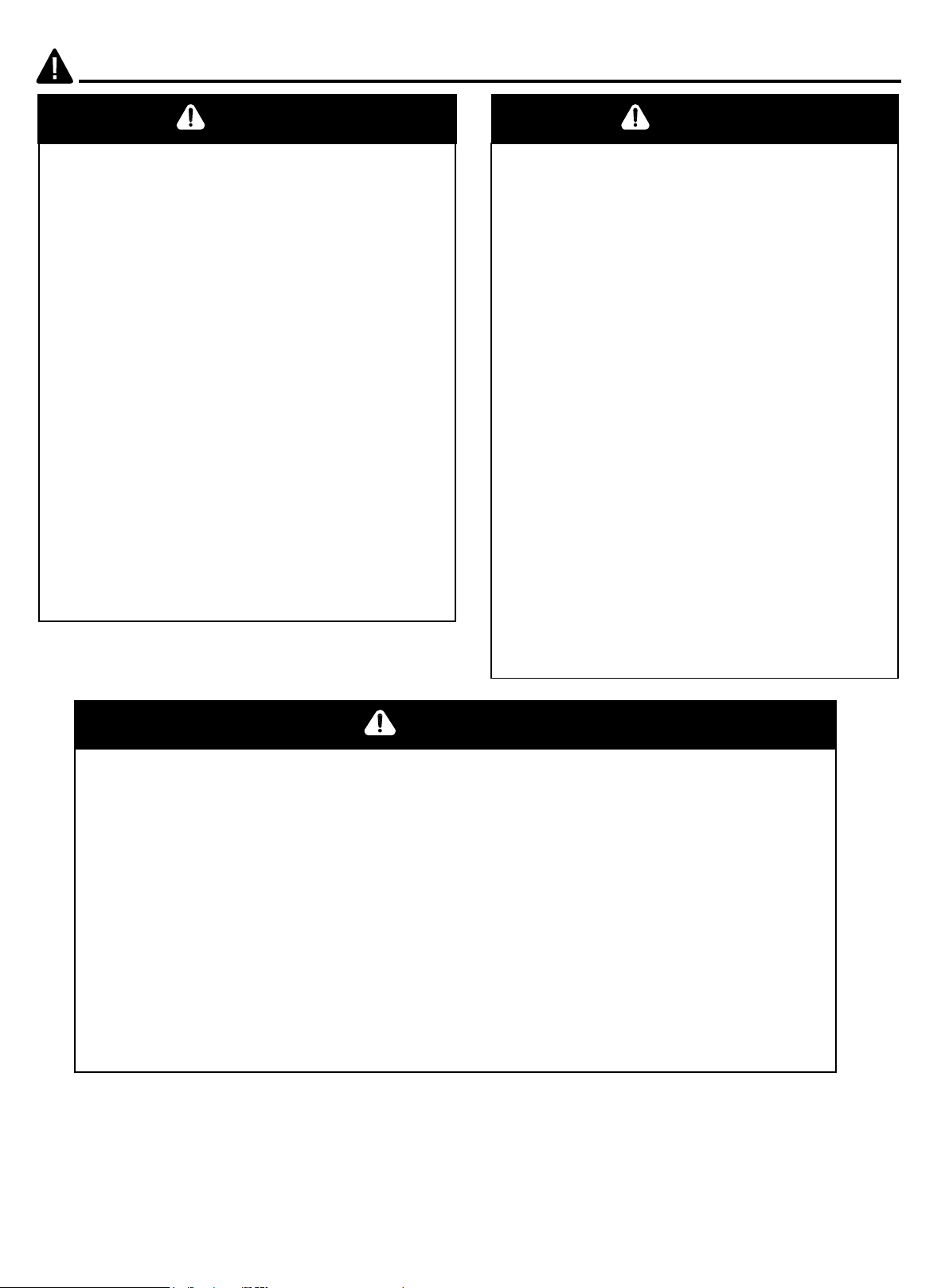
DANGER
• EXPLOSION - FIRE HAZARD
• Keep solid combustibles, such as building
materials, paper or cardboard, a safe distance
away from the heater as recommended by the
instructions.
• Provide adequate clearances around air
openings into the combustion chamber.
• Never use the heater in spaces that do or
may contain volatile or airborne combustibles,
or products such as gasoline, solvents, paint
thinner, dust particles or unknown chemicals.
• During operation, this product can be a
source of ignition. Keep heater area clear and
free from combustible materials, gasoline,
paint thinner, cleaning solvents and other
flammable vapors and liquids. Do not use
heater in areas with high dust content.
Minimum heater clearances from combustible
materials: three (3) feet from the sides and two
(2) feet from the top.
DANGER
• CARBON MONOXIDE HAZARD
• This heater is a combustion appliance. All
combustion appliances produce carbon
monoxide (CO) during the combustion
process. This product is designed to
produce extremely minute, non-hazardous
amounts of CO if used and maintained in
accordance with all warnings and
instructions. Do not block air flow into or
out of the heater.
• Carbon Monoxide (CO) poisoning
produces flu-like symptoms, watery eyes,
headaches, dizziness, fatigue and possibly
death. You can't see it and you can't smell
it. It's an invisible killer. If these symptoms
are present during operation of this product
get fresh air immediately!
• For outdoor use only.
• Never use inside house, or other
unventilated or enclosed areas.
• This heater consumes air (oxygen). Do not
use in unventilated or enclosed areas to
avoid endangering your life.
DANGER
• EXPLOSION - FIRE HAZARD
• Never store propane near high heat, open flames, pilot lights, direct sunlight, other
ignition sources or where temperatures exceed 120˚F.
• Propane vapors are heavier than air and can accumulate in low places. If you
smell gas, leave the area immediately.
• Never install or remove propane cylinder while heater is lighted, near flame,
pilot lights, other ignition sources or while heater is hot to touch.
• This heater is red hot during use and can ignite flammables too close to the burner.
Keep flammables at least 3 feet from sides and 2 feet from top. Keep gasoline and
other flammable liquids and vapors well away from heater.
• Store the propane cylinder outdoors in a well ventilated space out of reach of
children. Never store the propane cylinder in an enclosed area (house, garage, etc.).
If heater is to be stored indoors, disconnect the propane cylinder for outdoor storage.
4
Page 5
SAFETY INFORMATION
WARNING
We cannot foresee every use that may be
made of our heaters.
Check with your local fire safety authority if you
have questions about heater use.
Other standards govern the use of fuel gases
and heat producing products for specific uses.
Your local authorities can advise you about
these.
If no local codes exist, follow National Fuel Gas
Code, ANS Z223.1. In Canada, installation
must conform to local codes. If no local codes
exist, follow the current National standards of
CANADA CAN/CGA-B 149.2.
WARNING
California Proposition 65
Combustion by-products produced when using
this product contain chemicals known to the
state of California to cause cancer,
birth defects, and other reproductive harm.
WARNING
Do not store or use gasoline or other flammable
vapors and liquids in the vicinity of this or any
other appliance.An LP-cylinder not connected
for use shall not be stored in the vicinity of this
or any other appliance.
WARNING
Improper installation, adjustment, alteration,
service or maintenance can cause property
damage, injury or death. Read the installation,
operation and maintenance instructions
thoroughly before installing or servicing this
equipment.
WARNING
Certain materials or items, when stored under
the heater, will be subjected to radiant heat
and could be seriously damaged.
WARNING
BURN HAZARD
• Never leave heater unattended when hot
or in use.
• Keep out of reach of children.
5
Page 6
SAFETY INFORMATION
WARNING
• This product is fueled by propane gas. Propane
gas is invisible, odorless, and flammable. An
odorant is normally added to help detect leaks
and can be described as a “rotten egg” smell.
The odorant can fade over time so leaking gas is
not always detectable by smell alone.
• Propane gas is heavier than air and leaking
propane will sink to the lowest level possible.
It can ignite by ignition sources including matches,
lighters, sparks or open flames of any kind many
feet away from the original leak.
Use only propane gas set up for vapor withdrawal.
• Store or use propane gas in compliance with local
ordinances and codes or with ANS/NFPA 58.
Turn off propane when not in use.
CAUTION
SERVICE SAFETY
• Keep all connections and fittings clean. Make
sure propane cylinder valve outlet is clean.
• During set up, check all connections and
fittings for leaks using soapy water.
Never use a flame.
• Use as a heating appliance only. Never alter
in any way or use with any device.
WARNING
• Alert children and adults to the hazards of
high surface temperatures. Stay away from
these surfaces to avoid burning skin or
igniting clothing.
• Carefully supervise young children when in
the vicinity of the heater.
• Do not hang clothing or any other flammable
materials from the heater, or place on or near
the heater.
• Replace any guard or protective device
removed for servicing the appliance prior to
placing back in service.
• Installation and repair should be done by a
qualified service person. The heater should be
inspected before use and annually by a
qualified service person.
More frequent cleaning may be required as
necessary.
It is imperative that the control compartment,
burners,and circulating air passageway of the
appliance be kept clean.
PREPARATION
Before beginning assembly of product, make sure all parts are present. Compare parts with
package contents list and hardware contents above. If any part is missing or damaged, do not
attempt to assemble the product. Contact customer service for replacement parts.
Estimated Assembly Time: 60 minutes
Tools Required for Assembly (not included): Phillips Screwdriver and Leak Detection Solution.
6
Page 7
ASSEMBLY INSTRUCTIONS
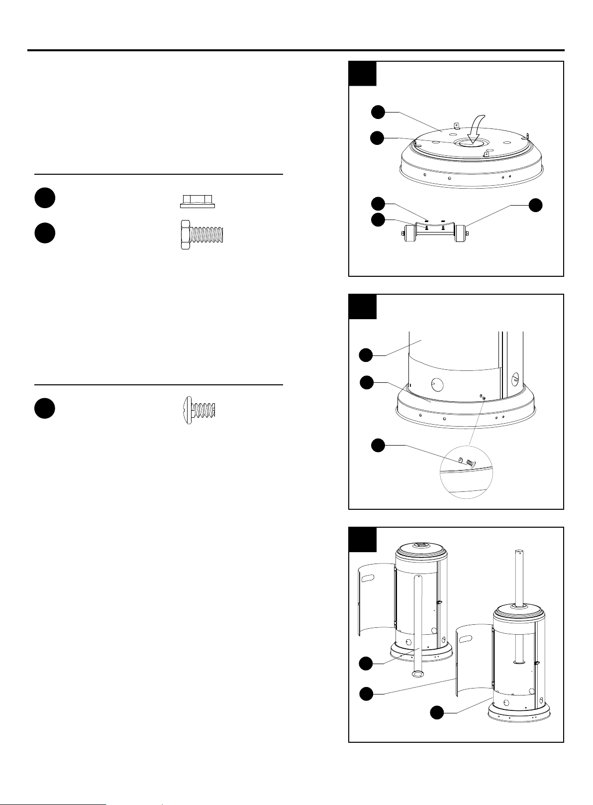
1. Line up holes on the bracket of wheel assembly (O)
with the corresponding holes on base (M), then insert
M8 x 16 mm bolts (BB) through holes. Hand tighten with
M8 flange nuts (AA). Be sure the wheel assembly (O) is
parallel to the base (M).
Note: To improve stability, the preassembled bucket (N)
can be filled with sand (not included).
Hardware Used
AA
BB
M8 Flange Nut
M8 x 16 mm Bolts
x 2
x 2
2. Attach cylinder housing (H) loosely to base (M) with
M5 x 8 mm screws (CC).
1
2
M
N
AA
BB
Fill sand
O
Hardware Used
CC
M5 x 8 mm Screw
x 4
3. Open the preassembled door (I) on cylinder housing
(H) and place post (J) through the hole on the top.
H
M
CC
3
J
I
H
TT
7
Page 8
ASSEMBLY INSTRUCTIONS
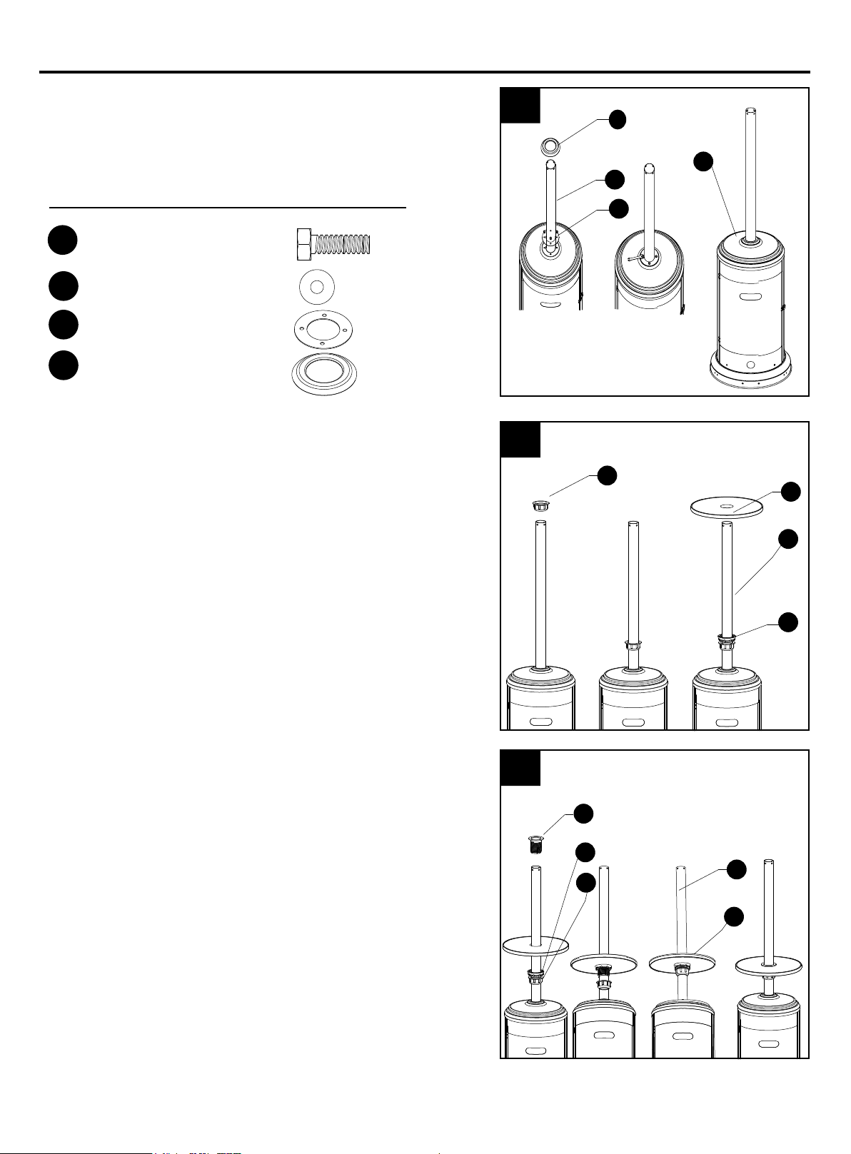
4. Secure post (J) to cylinder housing (H) using the
reinforced ring (NN), M6 x 10 mm bolts (DD) and
Φ6 small flat washers (EE). Fasten and cover
with the deck ring (OO).
Hardware Used
DD
M6 x 10 mm Bolt
EE
Φ6 Small Flat Washer
Reinforced Ring
NN
Deck Ring
OO
5. Slide fastening nut (G) down the post (J) with the
rounded side facing down. Next, slide the tightening
spacer (F) down the post (J) with the smaller side facing
down. Put the table (E) on the post (J) with the metallic
side facing up.
x 4
x 4
x 1
x 1
4
oo
H
J
NN
5
G
E
6. Insert the screw coupler (D) on the post (J), inserting
it through the middle of the table (E) on the post (J).
Thread the tightening spacer (F) on the bottom of the
table (E) counterclockwise onto the screw coupler (D).
Tighten securely to hold the table (E) to the screw
coupler (D). Thread the fastening nut (G)
counterclockwise. Tighten securely to lock in place.
Loosen the fastening nut (G) to adjust the position of the
table (E) on the post (J).
J
F
6
D
G
J
F
E
8
Page 9
ASSEMBLY INSTRUCTIONS
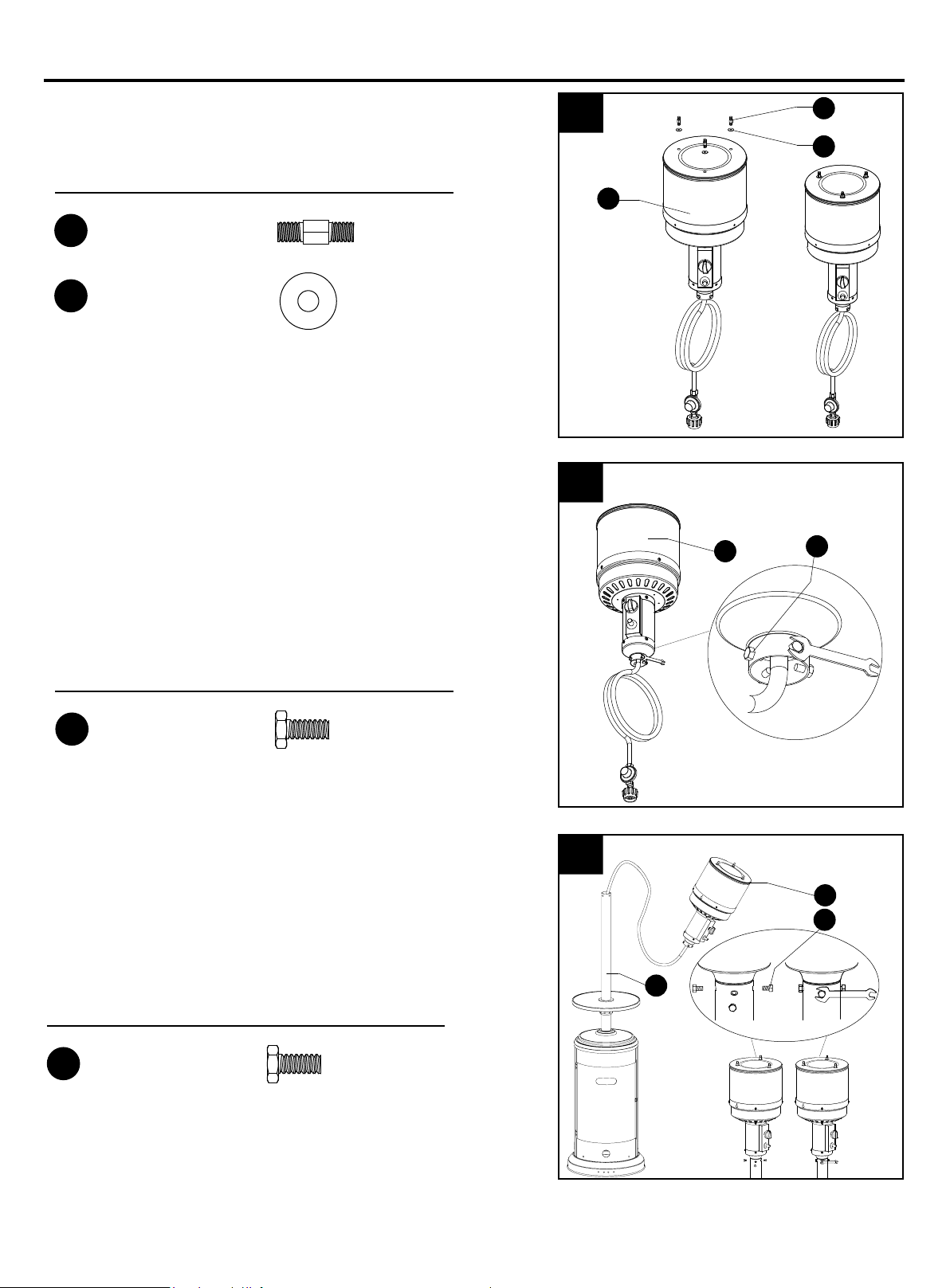
7. Attach reflector spacers (FF) and Ø8 washers
(GG) to the top of head assembly (C). Tighten the
reflector spacers (FF).
Hardware Used
FF
Reflector Spacer
GG
Φ8 Washer
x 3
x 3
8. Unscrew stainless steel bolts (LL) from head
assembly (C).
8
7
C
C
FF
GG
LL
Hardware Used
LL
Stainless Steel Bolt
x 4
9. Insert hose of head assembly (C) into post (J). Secure
head assembly (C) to post (J) with stainless steel
bolts (LL).
Note: The control knob on head assembly (C) should
be above the decal on post (J).
Hardware Used
LL
Stainless Steel Bolt
x 4
9
C
LL
J
9
Page 10

ASSEMBLY INSTRUCTIONS
10. Remove protective cover from reflector panel (A)
and reflector plate (B).
Note: In order to achieve proper alignment of
reflector sections, it may be necessary to loosen the
preassembled bolts prior to assembly and retighten
once complete.
11. Attach reflector panels (A) together using
M6 x 10 mm screws (II) and Φ6 washers (HH). Secure
loosely with cap nuts (JJ).
10
A
B
11
JJ
HH
Hardware Used
Φ 6 Washer
HH
II
M6 X 10 mm Screw
JJ
Cap Nut
x 3
x 3
x 3
12. Attach reflector plate (B) to reflector panels (A)
using M6 x 10 mm screws (II) and Φ6 washers (HH).
Secure loosely with cap nuts (JJ). Once properly
aligned, tighten all screws and the preassembled bolts.
Hardware Used
HH
Φ 6 Washer
x 6
II
12
JJ
II
M6 X 10 mm Screw
JJ
Cap Nut
x 6
x 6
HH
II
10
Page 11
ASSEMBLY INSTRUCTIONS
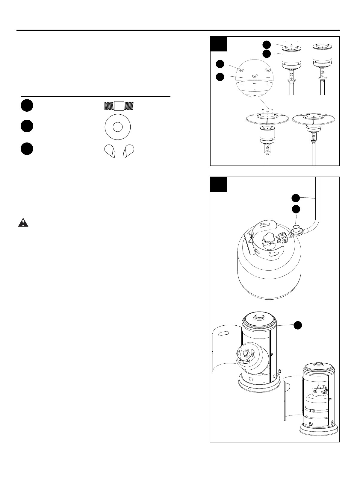
13. Slide Φ8 washers (GG) over the threaded ends of
reflectors spacers (FF). Attach reflector assembly to
head assembly (C). Place Φ8 washers (GG) over threaded
ends of reflector spacers (FF) sticking out through reflector
assembly and secure with wing nuts (KK).
Note: Do not overtighten.
Hardware Used
13
KK
GG
FF
C
FF
Reflector Spacer
GG
Φ8 Washer
KK
Wing Nut
x 3
x 6
x 3
14. Screw gas hose (K) and regulator (L) onto propane
cylinder (not included). Do not cross-thread.
Place the propane cylinder into the cylinder housing (H),
then close the door (I).
WARNING: Use a standard 20 lb. propane cylinder
only.
Use this heater only with a propane vapor withdrawal
supply system. See chapter 5 of the standard for
storage and handling of liquefied petroleum gas,
ANS/NFPA 58. Your local library or fire department
should have this book.
A minimum supply pressure of 0.4 P.S.I. is required for
the purpose of input adjustment for propane gas.
Storage of an appliance indoors is permissible only if
the cylinder is disconnected and removed from the
appliance. A cylinder must be stored outdoors in a
well-ventilated area out of the reach of children. A
disconnected cylinder must have dust caps tightly
installed and must not be stored in a building, garage
or any other enclosed area. The minimum permissible
gas supply pressure of 10 W.C. is required for purpose
of input adjustment. A minimum of 17,000 BTUs per
hour is the required input rating for a heater with a
rating less than full.
The pressure regulator and hose assembly supplied
with the appliance must be used.
The installation must conform with local codes, or in the
absence of local codes,with national fuel gas code,
ANS Z223.1/NFPA54, natural gas and propane
Installation Code, CSA B149.1, or propane storage and
handling code, B149.2.
14
K
J
L
H
11
Page 12
ASSEMBLY INSTRUCTIONS
A dented, rusted or damaged propane cylinder may be
hazardous and should be checked by your cylinder
supplier. Never use a propane cylinder with a damaged
valve connection.
The propane cylinder must be constructed and marked
in accordance with the specifications for LP gas
cylinders of the U.S. Department of Transportation
(DOT) or the standard for cylinders, spheres and
tubes for transportation of dangerous goods and
commission, CAN/CSA-B339.
The cylinder must have a listed overfilling prevention
device.
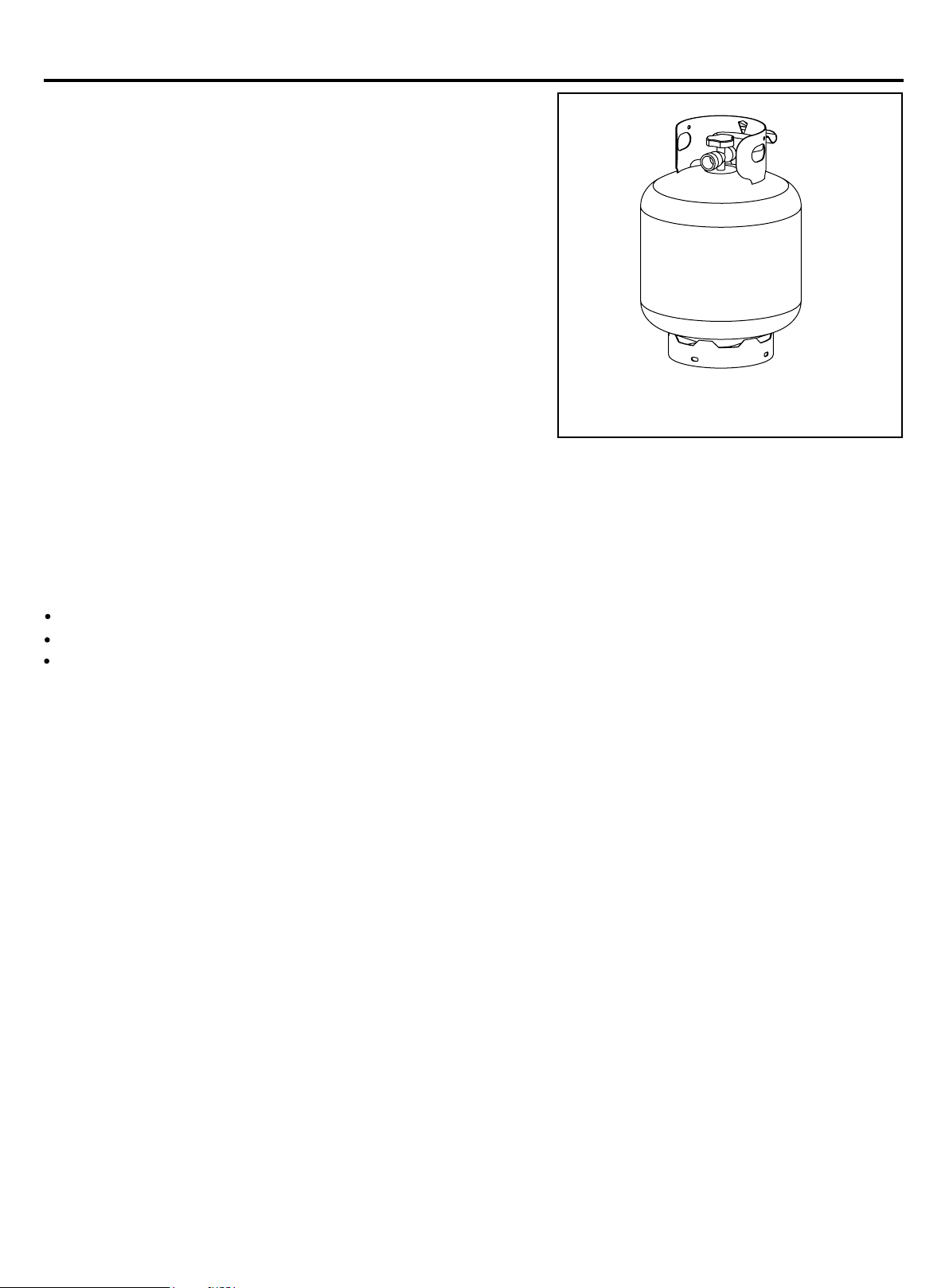
The cylinder must have a connection device compatible with the connection for the appliance.
The cylinder used must include a collar to protect the cylinder valve.
Standard 20 lb. tank
Never connect an unregulated propane cylinder to the heater.
Do not store a spare LP-gas cylinder under or near this appliance.
Never fill the cylinder beyond 80 percent full.
Place the dust cap on the cylinder valve outlet whenever the cylinder is not
in use. Only install the type of dust cap on the cylinder valve that is provided with
the cylinder valve. Other type of caps or plugs may result in leakage of propane.
12
Page 13
OPERATION INSTRUCTIONS
WARNING
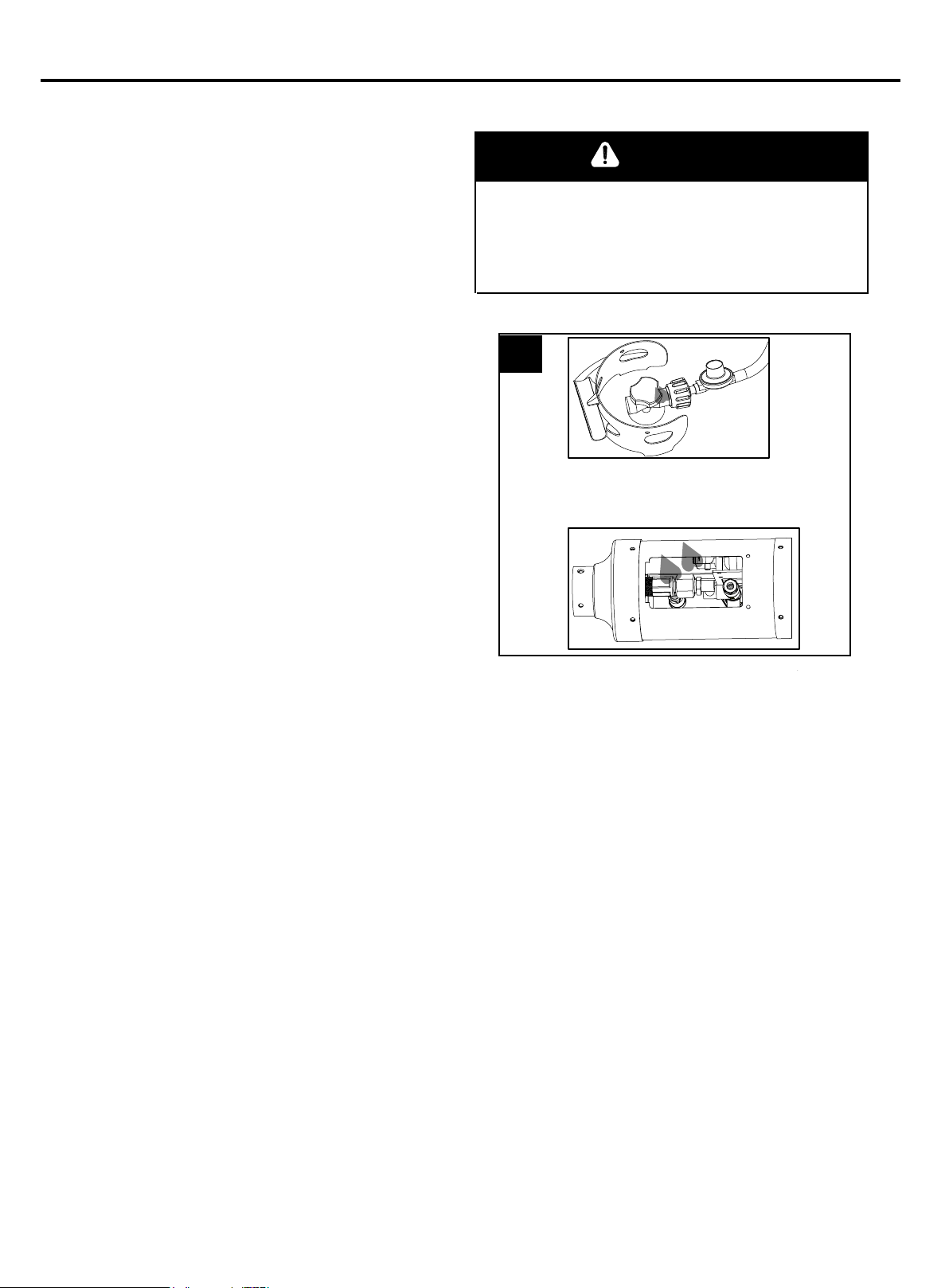
To check for a leak:
1. Make 2-3 oz. leak check solution (one part
liquid dishwashing detergent and three parts
water).
2. Apply several drops of solution where
regulator connects to cylinder and to all hose
and valve connections
3. Make sure all patio heater and light valves
are OFF.
4. Turn cylinder valve ON.
If bubbles appear at any connection, there is a
leak.
1. Turn cylinder valve OFF.
2. If leak is at regulator/cylinder valve connection:
Disconnect, reconnect, and perform another
leak check. Apply the soapy solution to all hose and
valve connections. If you continue to see bubbles
after several attempts, cylinder valve is defective
and should be returned to cylinder’s place of
purchase.
3. If leak is at hose/regulator connection:
This part is defective and you should contact the
customer service department for replacement.
• Perform all leak tests outdoors.
• Extinguish all open flames.
• NEVER leak test when smoking.
• Do not use the heater until all connections have been
leak tested and do not leak.
1
Regulator / Cylinder
connection
If NO bubbles appear at any connection, the connections are secure.
NOTE: Whenever gas connections are loosened or removed, you must perform a complete leak test.
13
Page 14
OPERATION INSTRUCTIONS
DANGER
• CARBON MONOXIDE HAZARD
• For outdoor use only. Never use inside house, or other
unventilated or enclosed areas. This heater consumes air
(oxygen). Do not use in unventilated or enclosed areas to
avoid endangering your life.
Caution: Do not attempt to operate until you have read and understand all General Safety Information
in this manual and all assembly is complete and leak checks have been performed.
Before Turning Gas Supply ON:
1. Your heater was designed and approved for outdoor use only. Do NOT use it inside a building,
garage, or any other enclosed area.
2. Make sure surrounding areas are free of combustible materials, gasoline, and other flammable
vapors or liquids.
3. Ensure that there is no obstruction to air ventilation. Be sure all gas connections are tight and
there are no leaks.
4. Be sure the cylinder cover is clear of debris. Be sure any component removed during assembly or
servicing is replaced and fastened prior to starting.
Before Lighting:
1. Heater should be thoroughly inspected before each use, and by a qualified service person at least
annually. If relighting a hot heater, always wait at least 5 minutes.
2. Inspect the hose assembly for evidence of excessive abrasion, cuts, or wear. Suspected areas
should be leak tested. If the hose leaks, it must be replaced prior to operation. Only use the
replacement hose assembly specified by manufacturer.
Lighting:
Note: This heater is equipped with a pilot light that allows for safer
startups and shutdowns. Pilot must
be lit before main burner can be started.
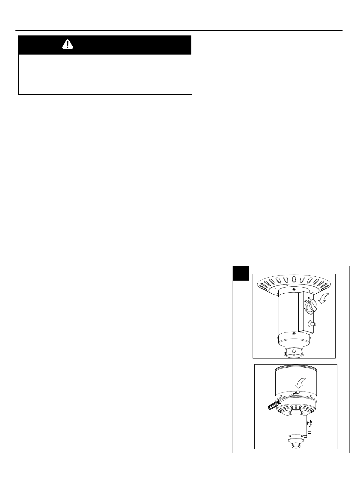
1. Turn the control knob to the “OFF” position.
2. Fully open LP cylinder valve.
3. Open viewing hole by sliding cover to either side.
4. Push control knob in and rotate to pilot position.
Note: For initial start or after any cylinder change, hold control
knob in for 2 minutes to purge air from
gas lines before proceeding.
2
14
Page 15
OPERATION INSTRUCTIONS
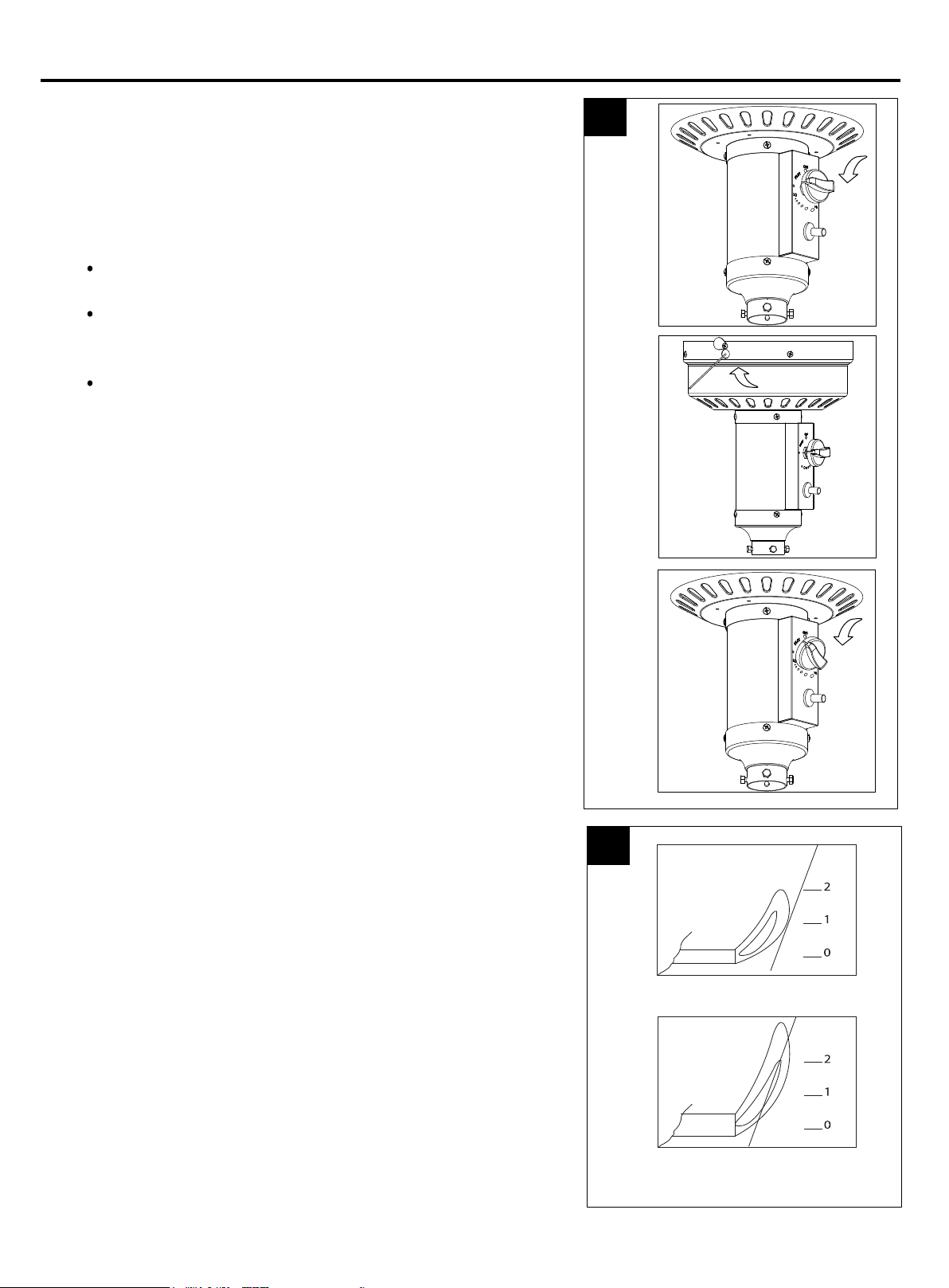
5. Push and release the igniter button until pilot flame
is visible through viewing hole.
6. Once the pilot is lit, continue to depress the control knob for
30 seconds.
7. If the pilot does not stay lit, repeat steps 4 to 6.
8. If after repeating steps 4 to 6 unit does not light,
then:
Push in control knob and turn counterclockwise to
“PILOT”.
As you are depressing the control knob, place long stem
lighter into the ignition hole on the emitter screen to light
the pilot
Repeat step 7.
3
9. Push in and turn the control knob to the “LOW”, then
release control knob. If you want a higher temperature,
push in the control knob and turn counterclockwise to the
“HIGH”.
Note: If pilot fails to remain lit, all valves should be closed
and a waiting period of at least 5 minutes should pass before
attempting to light
If you experience any ignition problem please consult
“Troubleshooting” on page 19.
Caution: Avoid inhaling fumes emitted from the heater’s first
use. Smoke and odor from the burning of oils used in
manufacturing will appear. Both smoke and odor will dissipate
after approximately 30 minutes. The heater should NOT
produce thick black smoke.
Note: The burner may be noisy when initially turned on.
To eliminate excessive noise from the burner,
turn the control knob to the PILOT position.
Then, turn the knob to the level of heat desired.
4
in.
in.
in.
Nomal
in.
in.
15
in.
Abnormal
Page 16
OPERATION INSTRUCTIONS
WARNING
WARNING
FOR YOUR SAFETY
Be careful when attempting to manually ignite this
heater. Holding in the control knob for more than 10
seconds before igniting the gas will cause a ball of
flame upon ignition.
When Heater is ON:
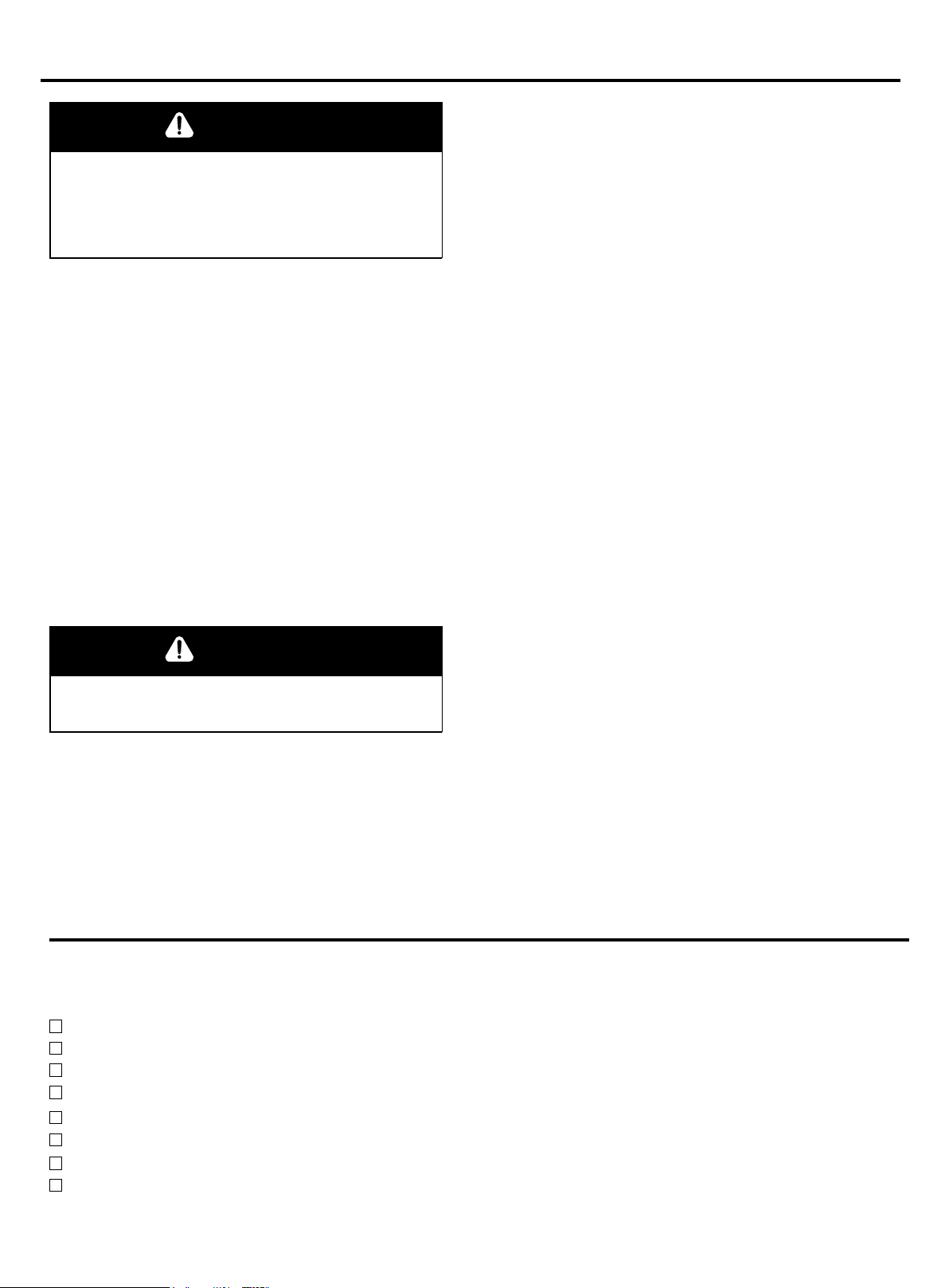
Emitter screen will become bright red due to intense heat. The color is more visible at night. Burner
will display tongues of blue and yellow flame. These flames should not be yellow or produce thick
black smoke, indicating an obstruction of airflow through the burners. The flame should be blue with
straight yellow tops. If excessive yellow flame is detected, turn off heater and consult “Troubleshooting”
on page 19.
Re-lighting:
Note: For your safety, control knob cannot be turned OFF without first depressing control knob in
PILOT position and then rotating it to OFF.
1. Turn control knob to OFF.
2. Wait at least 5 minutes, to let gas dissipate, before attempting to relight pilot.
3. Repeat the “Lighting” steps on prior page.
FOR YOUR SAFETY
Heater will be hot after use. Handle with extreme care.
Shut Down:
1. Turn control knob clockwise to PILOT. (Normally, burner will make a slight popping sound when
extinguished.) Burner will extinguish but PILOT will remain ON.
2. To extinguish PILOT, depress control knob and continue to turn it clockwise to OFF.
3. Turn cylinder valve clockwise to OFF and disconnect regulator when heater is not in use.
Note: After use, some discoloration of the emitter screen is normal.
OPERATION CHECKLIST
Perform this check before each use.
Before Operating:
I am familiar with entire owner’s manual and understand all precautions noted.
All components are properly assembled, intact and operable.
No alterations have been made.
All gas connections are secure and do not leak.
Wind velocity is below 10 mph.
Unit will operate at reduced efficiency below 40°F.
Heater is outdoors (outside any enclosure).
There is adequate fresh air ventilation.
16
Page 17
OPERATION INSTRUCTIONS
WARNING
Heater is away from gasoline or other flammable liquids or vapors.
Heater is away from windows, air intake openings, sprinklers and other water sources.
Heater is at least 24 in. on top and at least 36 in. on sides from combustible materials.
Heater is on a hard and level surface.
There are no signs of spider or insect nests.
All burner passages are clear.
All air circulation passages are clear.
Children ARE alerted of the hazards of high surface temperatures.
After Operation
1. Gas control is in OFF position.
2. Gas tank valve is OFF.
3. Disconnect gas line.
CARE AND MAINTENANCE
FOR YOUR SAFETY:
• Do NOT touch or move heater for at least 45 minutes after use.
• Reflector is hot to the touch.
• Allow reflector to cool before touching.
Keep exterior surfaces clean.
Use warm soapy water for cleaning. Never use flammable or corrosive cleaning agents.
While cleaning your unit, be sure to keep the area around the burner and pilot assembly dry at all
times. Do not submerge the control valve assembly. If the gas control is submerged in water, do
NOT use it. It must be replaced.
Keep the appliance area clear and free from combustible materials, gasoline and other
flammable vapors and liquids.
Do not obstruct the flow of combustion and ventilation air.
Keep the ventilation opening(s) of the cylinder enclosure free and clear from debris.
Air flow must be unobstructed. Keep controls, burner, and circulating air passageways clean.
17
Page 18

CARE AND MAINTENANCE
Spiders and insects can nest in burner or orifices. This dangerous condition can damage heater and
render it unsafe for use. Clean burner holes by using a heavy-duty pipe cleaner. Compressed air may
help clear away smaller particles.
Carbon deposits may create a fire hazard. Clean dome and burner screen with warm soapy water if
any carbon deposits develop.
Note: In a salt-air environment (such as near an ocean), corrosion occurs more quickly than normal.
Frequently check for corroded areas and repair them promptly.
Use high-quality automobile wax to help maintain the appearance of the heater. Apply to exterior
surfaces from the pole down. Do not apply to emitter screen or domes.
Between uses:
Turn Control Knob OFF.
Disconnect LP source.
Store heater upright in an area sheltered from direct contact with inclement weather (such as rain,
sleet, hail, snow, dust and debris).
If desired, cover heater to protect exterior surfaces and to help prevent build-up in air passages.
Note: Wait until heater is cool before covering.
During periods of extended inactivity or when transporting:
Turn Control Knob OFF.
Disconnect LP source and move to a secure, well-ventilated location outdoors.
Store heater upright in an area sheltered from direct contact with inclement weather (such as rain,
sleet, hail, snow, dust and debris).
If desired, cover heater to protect exterior surfaces and to help prevent build-up in air passages.
Never leave LP cylinder exposed to direct sunlight or excessive heat.
Note: Wait until heater is cool before covering.
Service
Only a qualified service person should repair gas passages and associated components.
Caution: Always allow heater to cool before attempting service.
18
Page 19

TROUBLESHOOTING
PROBLEM POSSIBLE CAUSE CORRECTIVE ACTION
1. Cylinder valve is closed 1. Open valve
Pilot won’t light
Note: Heater operates
at reduced efficiency
below 40ºF
Pilot won’t stay lit
Burner won’t light
2. Blockage in orifice or pilot tube
3. Air in gas line
4. Low gas pressure with cylinder valve
fully open
5. Igniter fails
1. Dirt built up around pilot
2. Connection between gas valve and pilot
assembly is loose
3. Thermocouple is not operating correctly
1. Propane cylinder is frosted over
2. Blockage in orifice
3. Control knob is not in ON position
2. Clean or replace orifice or pilot
tube
3. Open gas line and bleed it
(pressing control knob in) for not
more than 1 - 2 minutes or until
you smell gas
4. Turn cylinder valve OFF and
replace cylinder
5 .Use match to light pilot; obtain new
igniter and replace
1. Clean dirt from around pilot
2. Tighten connection and perform
leak check
3. Replace thermocouple
1. Wait until the propane cylinder
warms up and becomes unfrosted
2. Clear blockage
3. Turn control knob to ON
Burner flame is low
Thick black smoke
Gas odor with
extreme yellow
tipping of flame.
.
Heater glow is
excessively uneven.
Heater makes
popping noises.
1. Gas pressure is low
2. Outdoor temperature is less than 40ºF and
tank is less than 1/4 full
3. Control knob fully ON
4. Spiders and insects nest in burner or
orifices
1. Blockage in burner
1. Spiders and insects nest in burner or
orifices
1. Spiders and insects nest in burner or
orifices
1. Spiders and insects nest in burner or
orifices
1. Turn cylinder valve OFF and
replacecylinder
2. Use a full cylinder
3. Check burner and orifices for
blockage
4. Clean burner and orifices
1. Remove blockage and clean burner
inside and outside
1. Clean burner and orifices
1. Clean burner and orifices
1. Clean burner and orifices
Carbon build-up
1. Dirt or film on reflector and burner screen
19
1. Clean reflector and burner screen
Page 20

ONE-YEAR LIMITED WARRANTY
CUSTOMERS IN USA
Do not return this product to the store where you purchased it. Please call 1-888-775-1330
for assistance.
CUSTOMERS IN CANADA
Only return this product to the store if it was purchased within 90 days. If you have problems
after 90 days of purchase, please CALL 1-888-775-1330. DATED PROOF OF PURCHASE
REQUIRED FOR WARRANTY SERVICE.
This product is inspected, tested and carefully packaged to minimize the chance of damage
during shipment. If a part (excluding light bulbs and fuses*) within one year from the date of
purchase proves to be defective in material or fabrication under normal use, the part will be
repaired or replaced. The Company's obligation under the warranty is to replace or repair
defective parts at our discretion. Any expenses or damage resulting from the installation,
removal or transportation of the product will the responsibility of the owner and are not
covered by this warranty. The owner assumes all other risks arising out from the use or
misuse of the product. The warranty will be void if the product damage or failure is deemed
by the Company to be caused by accident, alteration, misuse, abuse, incorrect installation or
removal, or connection to an incorrect power source by the owner. The Company neither
assumes, nor authorizes any person or entity to assume for it any obligation or liability
associated with its products.
* Light bulbs and fuses are not covered under this warranty.
If you have any questions regarding the warranty or service, please call our toll
free number: 1-888-775-1330.
Distributed by:
AZ Patio Heaters, LLC
Toll Free Number 1-888-775-1330
Sales Service and Repair
www.azpatioheaters.com
20
Page 21
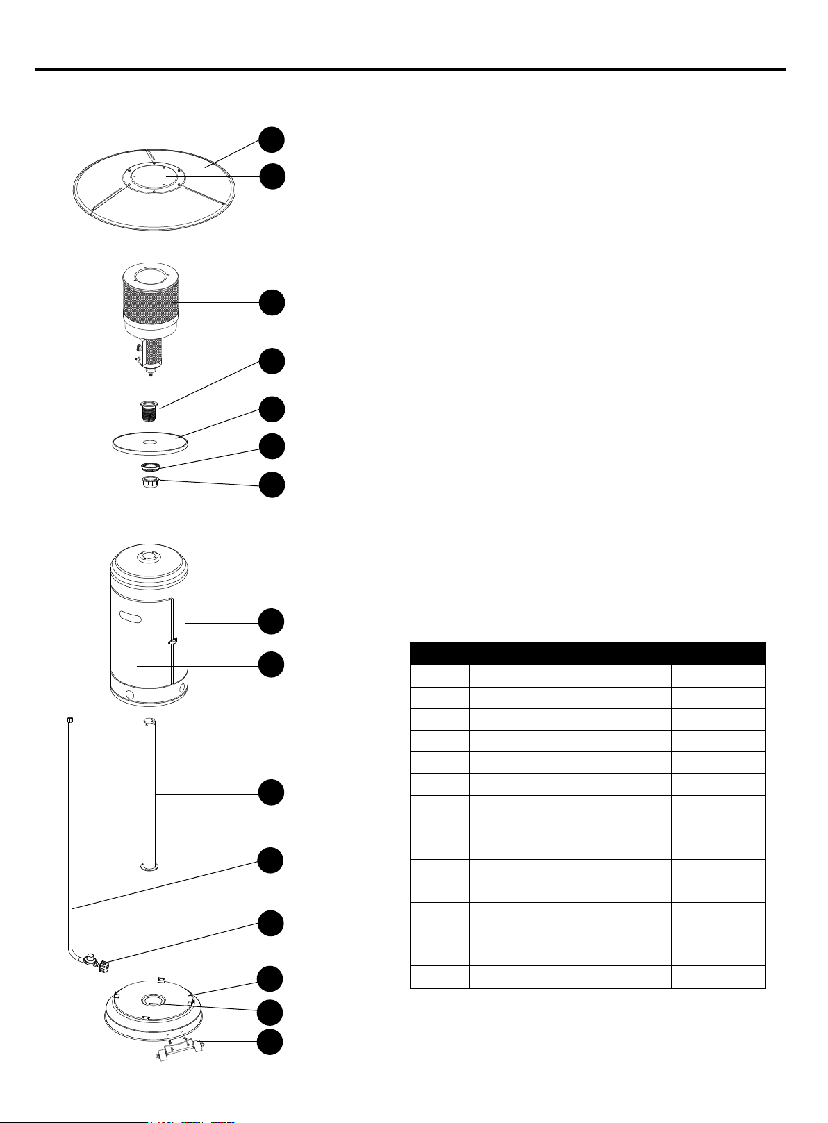
REPLACEMENT PARTS LIST
For replacement parts, call our customer service department at 1-888-775-1330,
7 a.m. - 4 p.m., PST, Monday - Friday.
A
B
C
D
E
F
G
H
NOITPIRCSED TRAP QUANTITY
I
J
K
L
M
A
B
C
D
E
F
G
H
I
J
K
L
M
N
O
Reflector Panel
Reflector Plate
Head Assembly
Screw Coupler
Table
Tightening Spacer
Fastening Nut
Cylinder Housing
Door (preassembled)
Post
Gas Hose
Regulator
Base
Bucket (preassembled)
Wheel Kit
3
1
1
1
1
1
1
1
1
1
1
1
1
1
1
N
Printed in China
O
21
 Loading...