

Page 1

Vision Box
User Manual
UD04763B
Page 2

Vision Box User Manual
1
TABLE OF CONTENTS
Chapter 1 Overview ............................................................................................... 6
1.1 Introduction .................................................................................................. 6
1.2 Features ........................................................................................................ 6
1.3 Specifications ............................................................................................... 6
Chapter 2 Panels and Connections ....................................................................... 8
2.1 Dimensions................................................................................................... 8
2.2 Installation .................................................................................................... 8
2.3 Panels ........................................................................................................... 9
2.4 GPIO Connections ..................................................................................... 11
2.4.1 Pin Definitions .................................................................................. 11
2.4.2 OutputConnections............................................................................ 11
Chapter 3 Operation of I/O and Demo .............................................................. 13
3.1 Input/Output Pattern ................................................................................... 13
3.2 Operation of Demo..................................................................................... 13
3.2.1 Selecting Pattern ............................................................................... 14
3.2.2 Triggering by I/O .............................................................................. 14
3.2.3 Triggering by Serial Port ................................................................... 15
3.2.4 Configuring Serial Port Property ...................................................... 16
Chapter 4 Video Output Configuration ............................................................. 19
4.1 HDMI Video Output .................................................................................. 19
4.2 Remote Access ........................................................................................... 19
Chapter 5 System and Driver Installation ......................................................... 20
5.1 Installing Operating System ....................................................................... 20
5.2 Installing the Driver ................................................................................... 20
Page 3

Vision Box User Manual
2
Quick Start Guide
COPYRIGHT © 2017 Hangzhou Hikvision Digital Technology Co., Ltd.
ALL RIGHTS RESERVED.
Any and all information, including, among others, wordings, pictures, graphs are the properties of
Hangzhou Hikvision Digital Technology Co., Ltd. or its subsidiaries (hereinafter referred to be
“Hikvision”). This user manual (hereinafter referred to be “the Manual”) cannot be reproduced,
changed, translated, or distributed, partially or wholly, by any means, without the prior written
permission of Hikvision. Unless otherwise stipulated, Hikvision does not make any warranties,
guarantees or representations, express or implied, regarding to the Manual.
About this Manual
This Manual is applicable to Vision Box.
The Manual includes instructions for using and managing the product. Pictures, charts, images and
all other information hereinafter are for description and explanation only. The information
contained in the Manual is subject to change, without notice, due to firmware updates or other
reasons. Please find the latest version in the company website
(http://www.hikrobotics.com/en/index.aspx).
Please use this user manual under the guidance of professionals.
Trademarks Acknowledgement
and other Hikvision’s trademarks and logos are the properties of Hikvision in various
jurisdictions. Other trademarks and logos mentioned below are the properties of their respective
owners.
Legal Disclaimer
TO THE MAXIMUM EXTENT PERMITTED BY APPLICABLE LAW, THE PRODUCT DESCRIBED, WITH ITS
HARDWARE, SOFTWARE AND FIRMWARE, IS PROVIDED “AS IS”, WITH ALL FAULTS AND ERRORS,
AND HIKVISION MAKES NO WARRANTIES, EXPRESS OR IMPLIED, INCLUDING WITHOUT LIMITATION,
MERCHANTABILITY, SATISFACTORY QUALITY, FITNESS FOR A PARTICULAR PURPOSE, AND
NON-INFRINGEMENT OF THIRD PARTY. IN NO EVENT WILL HIKVISION, ITS DIRECTORS, OFFICERS,
EMPLOYEES, OR AGENTS BE LIABLE TO YOU FOR ANY SPECIAL, CONSEQUENTIAL, INCIDENTAL, OR
INDIRECT DAMAGES, INCLUDING, AMONG OTHERS, DAMAGES FOR LOSS OF BUSINESS PROFITS,
BUSINESS INTERRUPTION, OR LOSS OF DATA OR DOCUMENTATION, IN CONNECTION WITH THE
USE OF THIS PRODUCT, EVEN IF HIKVISION HAS BEEN ADVISED OF THE POSSIBILITY OF SUCH
DAMAGES.
REGARDING TO THE PRODUCT WITH INTERNET ACCESS, THE USE OF PRODUCT SHALL BE WHOLLY
AT YOUR OWN RISKS. HIKVISION SHALL NOT TAKE ANY RESPONSIBILITES FOR ABNORMAL
OPERATION, PRIVACY LEAKAGE OR OTHER DAMAGES RESULTING FROM CYBER ATTACK, HACKER
ATTACK, VIRUS INSPECTION, OR OTHER INTERNET SECURITY RISKS; HOWEVER, HIKVISION WILL
PROVIDE TIMELY TECHNICAL SUPPORT IF REQUIRED.
SURVEILLANCE LAWS VARY BY JURISDICTION. PLEASE CHECK ALL RELEVANT LAWS IN YOUR
JURISDICTION BEFORE USING THIS PRODUCT IN ORDER TO ENSURE THAT YOUR USE CONFORMS
THE APPLICABLE LAW. HIKVISION SHALL NOT BE LIABLE IN THE EVENT THAT THIS PRODUCT IS
USED WITH ILLEGITIMATE PURPOSES.
IN THE EVENT OF ANY CONFLICTS BETWEEN THIS MANUAL AND THE APPLICABLE LAW, THE LATER
PREVAILS.
Page 4

Vision Box User Manual
3
Regulatory Information
FCC Information
Please take attention that changes or modification not expressly approved by the party
responsible for compliance could void the user’s authority to operate the equipment.
FCC compliance: This equipment has been tested and found to comply with the limits for a Class A
digital device, pursuant to part 15 of the FCC Rules. These limits are designed to provide
reasonable protection against harmful interference when the equipment is operated in a
commercial environment. This equipment generates, uses, and can radiate radio frequency energy
and, if not installed and used in accordance with the instruction manual, may cause harmful
interference to radio communications. Operation of this equipment in a residential area is likely to
cause harmful interference in which case the user will be required to correct the interference at
his own expense.
FCC Conditions
This device complies with part 15 of the FCC Rules. Operation is subject to the following two
conditions:
1. This device may not cause harmful interference.
2. This device must accept any interference received, including interference that may cause
undesired operation.
EU Conformity Statement
This product and - if applicable - the supplied accessories too are marked with "CE" and
comply therefore with the applicable harmonized European standards listed under the
EMC Directive 2014/30/EU, the LVD Directive 2014/35/EU, the RoHS Directive 2011/65/EU.
2012/19/EU (WEEE directive): Products marked with this symbol cannot be disposed of
as unsorted municipal waste in the European Union. For proper recycling, return this
product to your local supplier upon the purchase of equivalent new equipment, or
dispose of it at designated collection points. For more information see: www.recyclethis.info
2006/66/EC (battery directive): This product contains a battery that cannot be disposed
of as unsorted municipal waste in the European Union. See the product documentation
for specific battery information. The battery is marked with this symbol, which may
include lettering to indicate cadmium (Cd), lead (Pb), or mercury (Hg). For proper recycling, return
the battery to your supplier or to a designated collection point. For more information see:
www.recyclethis.info
Industry Canada ICES-003 Compliance
This device meets the CAN ICES-3 (A)/NMB-3(A) standards requirements.
Page 5
Vision Box User Manual
4
Applicable Models
This manual is applicable to the MV-VB2100-032/120G Vision Box.
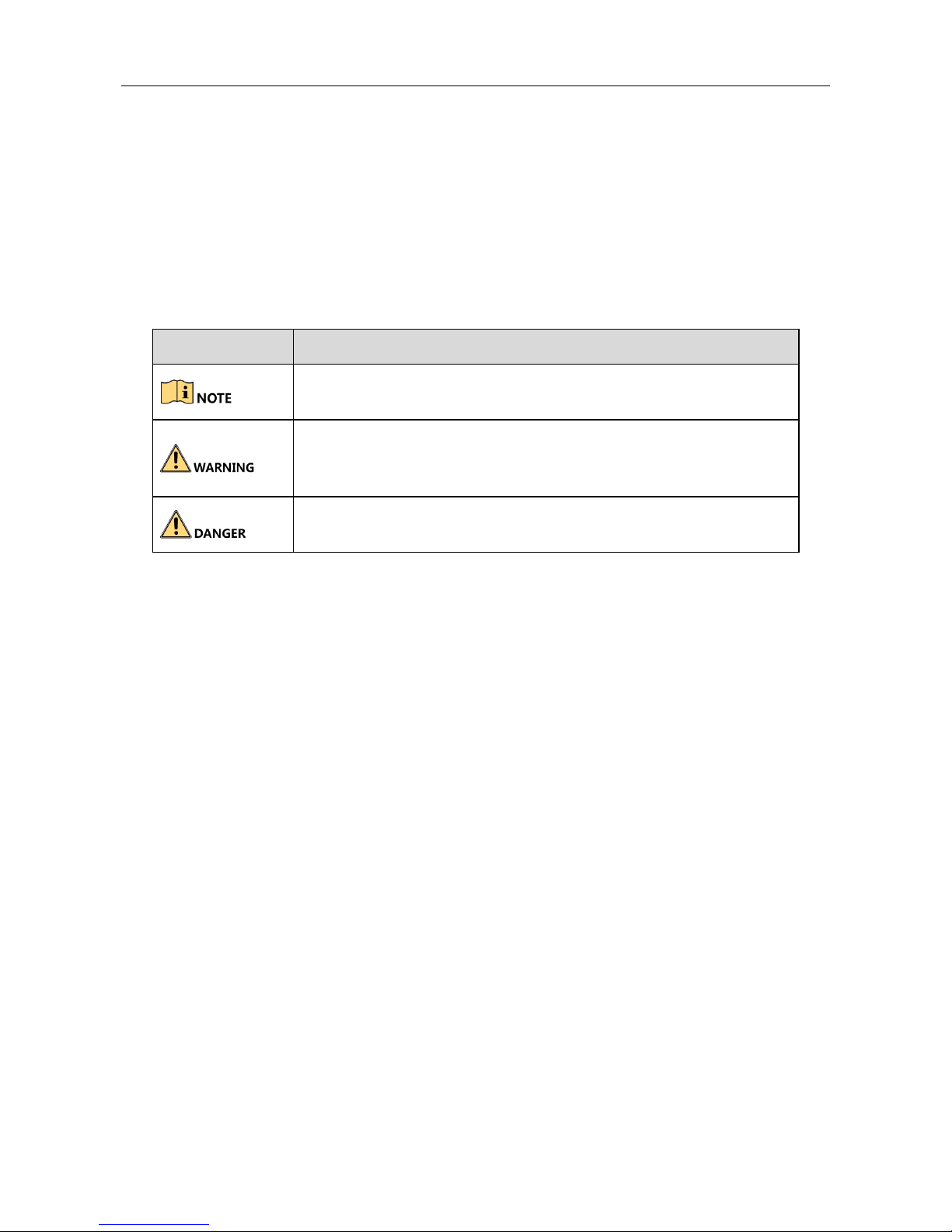
Symbol Conventions
The symbols that may be found in this document are defined as follows.
Symbol
Description
Provides additional information to emphasize or supplement
important points of the main text.
Indicates a potentially hazardous situation, which if not avoided,
could result in equipment damage, data loss, performance
degradation, or unexpected results.
Indicates a hazard with a high level of risk, which if not avoided, will
result in death or serious injury.
Page 6

Vision Box User Manual
5
Safety Instructions
Proper configuration of all passwords and other security settings is the responsibility of the
installer and/or end-user.
In the use of the product, you must be in strict compliance with the electrical safety
regulations of the nation and region. Please refer to technical specifications for detailed
information.
Input voltage should meet both the SELV (Safety Extra Low Voltage) and the Limited Power
Source with 100~240 VAC or 12 VDC according to the IEC60950-1 standard. Please refer to
technical specifications for detailed information.
Do not connect several devices to one power adapter as adapter overload may cause
over-heating or a fire hazard.
Please make sure that the plug is firmly connected to the power socket.
If smoke, odor or noise rise from the device, turn off the power at once and unplug the power
cable, and then please contact the service center.
Preventive and Cautionary Tips
Before connecting and operating your device, please be advised of the following tips:
Ensure unit is installed in a well-ventilated, dust-free environment.
Unit is designed for indoor use only.
Keep all liquids away from the device.
Ensure environmental conditions meet factory specifications.
Ensure unit is properly secured to a rack or shelf. Major shocks or jolts to the unit as a result of
dropping it may cause damage to the sensitive electronics within the unit.
Use the device in conjunction with an UPS if possible.
You shall acknowledge that the use of the product with Internet access might be under
network security risks. For avoidance of any network attacks and information leakage, please
strengthen your own protection. If the product does not work properly, please contact with
your dealer or the nearest service center.
Power down the unit before connecting and disconnecting accessories and peripherals.
Improper use or replacement of the battery may result in hazard of explosion. Replace with
the same or equivalent type only. Dispose of used batteries according to the instructions
provided by the battery manufacturer.
Page 7

Vision Box User Manual
6
Chapter 1 Overview
1.1 Introduction
Designed for the control system, the Vision Box has integrated with the various interfaces and
image processing algorithms in the machine vision applications, featuring stable performance,
compact structure, fast response, etc. The Box adopts the Intel® AtomTM E3845 Quad-core SoC
processor, with the excellent computing performance, low consumption and outstanding system
expandability.
It can be widely applied to the robots, medical instruments, laser equipment, numerical control
machine tools, package test, etc.
1.2 Features
Onboard Intel E3845 SOC, 1.91GHz CPU, providing 200% CPU and 350% GPU performance
more than the last-generation D525/D2550 processor.
Adoption of Gen7 GPU greatly enhances the image processing performance.
Compact structure design
4GB DDR3L memory
-10 ºC to +50 ºC fanless working temperature
Two Intel-chip Gigabit network interfaces, with the enhanced surge-protection design to
ensure the stable access by machine vision cameras.
Two independent HDMI video outputs.
8 GPIO.
1.3 Specifications
Model
MV-VB2100-032G
MV-VB2100-120G
Processor
Intel E3845 chip, 4-core 1.91GHz
Memory
4GB DDR3L-1333
Operating System
Win7, Win8, Linux
Graphic/Video
Gen7 GPU
Hardware accelerated H.264 video encoding
Hardware accelerated multiple video decoding
formats
Page 8

Vision Box User Manual
7
Display
2 independent HDMI outputs at 2560×1600
resolution
Network
2 Intel i210 Gigabit Ethernet chips
2 RJ45 Gigabit Ethernet interfaces
Enhanced surge-protection
Storage
32GB SSD
120GB SSD
USB interface
1 × USB 3.0 host interface
1 × composite interface (USB3.0 client+ USB2.0 host)
2 × USB 2.0 host interface
External
interfaces
1 RS-485(half-duplex)
1 RS-232
GPIO
4 inputs/4 outputs
Audio
HAD Stereo Line-out
and single-track Mic-in
Power supply
24 VDC /1A
Consumption
(without hard
disk)
≤ 12 W
Working
temperature
-10 ºC to +50 ºC
Working
humidity
10% to 90%RH non-condensing
Dimensions
(W × D × H)
135mm × 91mm × 45mm (5.3inch × 3.6inch × 1.8inch)
Page 9

Vision Box User Manual
8
Chapter 2 Panels and Connections
2.1 Dimensions
Refer to the following figure for the outline and dimensions of the Vision Box:
134
.8
7.2
91 45
50
80
4-M3 4
Figure 2-1 Outline and Dimensions
2.2 Installation
Use four M3 set screws to install the Vision Box.
Page 10

Vision Box User Manual
9
Figure 2-2 Installation
2.3 Panels
Refer to the following figure for the interfaces on the panel of Vision Box:
USB3.0
AUDIO
RS485
LAN
DC 24V
RS232
B
A
千兆网口
RS232接口
USB接口
USB2.0
音频接口
RS485接口
电源接口
LAN
PWR
HDD
HDMI1
USB2.0 HDMI2
G 4 3 2 1G C 4 3 2 1
1 2 3 4 G 1 2 3 4 C G
DI DO
千兆网口
电源指示灯
HDMI接口
电源开关
GPIO接口
USB2.0接口
硬盘读写灯
1
2
3
4
5
6
7
8
9
10
13
11
12
Figure 2-3 Indicators and Interfaces on the Panels
Table 2-1 Panel Description
No.
Name
Descriptions
1
HDMI1/HDMI2
HDMI video output at up to 2560×1600 resolution.
2
POWER
Power indicator turns yellow when the device is
running.
Page 11

Vision Box User Manual
10
3
LAN Interface
RJ-45 10/100/1000 Mbps self-adaptive Ethernet
interface.
4
USB 2.0 interface
2 USB 2.0 Universal Serial Bus (USB) interfaces for
additional devices such as USB mouse and USB Hard
Disk Drive (HDD).
5
HDD
HDD indicator blinks red when data is being read
from or written to HDD.
6
GPIO
4 GPIO input and 4 GPIO output connectors.
7
Power
Switch for turning on/off the device.
8
USB 3.0 interface
1 USB 3.0 host interface
1 composite interface (USB3.0 client+ USB2.0 host)
9
RS-232 Interface
Connector for RS-232 devices.
10
LAN Interface
RJ-45 10/100/1000 Mbps self-adaptive Ethernet
interface.
11
Power Supply
24V DC,1A power supply
12
RS-485 Interface
Connector for RS-485 devices.
13
Audio In/Out
HAD Stereo Line-out and single-track Mic-in
Page 12

Vision Box User Manual
11
2.4 GPIO Connections
2.4.1 Pin Definitions
Refer to the following table for the pin definitions of GPIO inputs and outputs:
Table 2-2 Pin Definitions
Pin No.
Name
Definition
1
DI1
Optical isolation input 1
2
DI2
Optical isolation input 2
3
DI3
Optical isolation input 3
4
DI4
Optical isolation input 4
5
IN_GND
Optical isolation input GND
6
DO1
Optical isolation output 1
7
DO2
Optical isolation output 2
8
DO3
Optical isolation output 3
9
DO4
Optical isolation output 4
10
COMMON
Common
11
OUT_GND
Optical isolation output
GND
The voltage for the optical isolation input is: 10-30V high TTL, 0-2V TTL.
The voltage for the optical isolation output is: 5-30V high TTL, 0-1.1V TTL, max. 90mA reverse
current.
2.4.2 OutputConnections
Connection Mode A
The following connection can be adopted when the external device are connected, such as the LED,
relay, beeper, etc.
Page 13

Vision Box User Manual
12
Figure 2-4 Connection Mode A
Connection Mode B
When the output is used as the signal, you need to add a pull-up resistor (12V/1~ 4k, 24V/2 ~ 8k)
between the Common and Output to form a level signal. Refer to the following figure:
Figure 2-5 Connection Mode B
Page 14

Vision Box User Manual
13
Chapter 3 Operation of I/O and Demo
3.1 Input/Output Pattern
The input channel can be triggered by the upper level device control or the I/O control. And the
PWM output and pulse output are provided.
The following three configuration patterns are selectable:
Pattern 1 (All): triggering input by I/O or serial port triggering is configurable.
Pattern 2: triggering input by I/O is configurable only.
Pattern 3: triggering input by serial port enabling command is configurable only.
3.2 Operation of Demo
Open the Vision Box Mfc Demo to enter the following window:
Figure 3-1 Demo Interface
Please go to the official website to download the latest Demo.
Page 15

Vision Box User Manual
14
3.2.1 Selecting Pattern
Three patterns are selectable: PATTERN_ALL (pattern 1), PATTERN_I_O (pattern 2) and
PATTERN_SERIAL (pattern 3).
Step 1 Check the checkbox of Show to enable the settings.
Step 2 Select a pattern from the drop-down list.
PATTERN_ALL: trigger the input by I/O or serial port enabling as user demand.
PATTERN_I_O: trigger input by I/O only.
PATTERN_SERIAL: trigger input by serial port enabling command only.
Step 3 Click the SendCommand to complete the settings.
Figure 3-2 Select Pattern
3.2.2 Triggering by I/O
Task1: Input Settings
The input settings must be configured when the external signal (e.g., photoelectric sensor) is used
for triggering the input port.
Figure 3-3 Input Triggering Pattern
Step 1 Check the checkbox of Show to enable the settings.
Step 2 Select the SSET_STATU mode to configure the parameters.
1) Check the checkbox of port 1-4 as demand.
2) Select the IO_INPUT from the drop-down list.
3) Check the checkbox of output ports.
4) Select the ACTION_START and configure it to EDGE_RISING or EDGE_FALLING triggering
mode.
5) Set the delay time (ms) and select the NOTICE_ON or NOTICE_SEND to send the notice or
not.
6) Click the SendCommand to complete the settings.
Page 16

Vision Box User Manual
15
Step 3 Repeat the sub steps 1) to 3) of Step 2, and select the ACTION_END and configure it to
EDGE_RISING or EDGE_FALLING triggering mode. And repeat the sub steps 5) to 6) of Step 2
to complete the settings.
Task2: Output Settings
The PWM output and pulse output can be configured. The PWM output setting is taken as the
example in the following instructions.
Figure 3-4 PWM Output Settings
Step 1 Select the SSET_STATU mode to configure the parameters.
Step 2 Check the checkbox of port 1-4 as demand.
Step 3 Select the IO_PWM_OUT from the drop-down list.
Step 4 Set the parameters of pulse width (ms), cycle time (ms), and duration (ms).
You can enter Max in the duration to set continuous outputting.
Step 5 Click the SendCommand to complete the settings.
3.2.3 Triggering by Serial Port
Purpose
The serial port parameters must be configured when you use it to trigger the input. The pulse
output setting is taken as the example in the following instructions.
Figure 3-5 Pulse Output Settings
Step 1 Set the pulse parameters.
1) Select the SSET_STATU mode to configure the parameters.
2) Check the checkbox of port 1-4 as demand.
3) Select the IO_PULSE_OUT from the drop-down list.
4) Select the LEVEL_HIGHT, and set the parameters of pulse number, duration (ms) and
pulse interval (ms).
Page 17

Vision Box User Manual
16
You can enter Max in the duration to set continuous outputting.
5) Click the SendCommand to complete the settings.
Step 2 Select the STROBE_STATUS mode and set the ENABLE_START to start enabling the serial port.
Click the SendCommand to complete the settings
Step 3 Select the STROBE_STATUS mode and set the ENABLE_END to end the serial port enabling.
Click the SendCommand to complete the settings
3.2.4 Configuring Serial Port Property
In the original operating system, the default port used by GPIO is Com2, with the baud rate of
115200, 8 data bits, and 1 stop bit.
Hardware of Vision Box serial port is corresponding to COM port, which can be seen and
configured through “Device Manager” 一> “Ports (COM & LPT)”. Right click “COM1”, select
“Properties”.
Figure 3-6 Serial port property entrance interface
In “Communications Port (Com1) Properties” interface, select “Resources” page, as shown in
Figure. IRQ information can be found in this window, IRQ corresponded to each COM port is
shown in Table 3-1.
Page 18

Vision Box User Manual
17
Figure 3-7 Serial port “Resource” window
Table 3-1 Information correspond to function and serial port hardware IRQ
Original Serial
Port No.
Correspond
Function
IRQ Information
COM1
RS232
0x00000004(04)
COM2
GPIO
0x0000000A(10)
COM3
RS485
0x00000003(03)
COM4
NULL
0x0000000B(11)
Click “Advanced” in “Port Settings” page of “Communications Port (Com1) Properties” interface,
modify the serial port number correspond to hardware in system, as shown in Figure 3-8.
Page 19

Vision Box User Manual
18
Figure 3-8 Hardware modification window correspond to serial port
The Com1 of the Vision Box corresponds to the RS-232, the Com3 to RS-485, and the Com4 is null.
Figure 3-9 Serial Port Property
Page 20

Vision Box User Manual
19
Chapter 4 Video Output Configuration
4.1 HDMI Video Output
The Vision Box provides two HDMI output interfaces for connection to the HDMI display unit (or to
VGA display unit with HDMI-to-VGA adapter). Up to 2560 x 1600 resolution is supported.
4.2 Remote Access
The Vision Box is installed with the MVWhere client software for device access to the LAN. Use the
MVWhere client software to find the IP address of the controller for remote access.
Figure 4-1 Use MVWhere to Find Box IP Address
Default user name: administrator, password: 123456. Based on the security requirements, it is
strongly recommended that the user modify the initial password when first using Vision Box.
Page 21

Vision Box User Manual
20
Chapter 5 System and Driver Installation
5.1 Installing Operating System
The operating system can be installed via USB storage device (e.g., USB DVD, USB mobile disk, etc.).
Connect the USB storage device and operate the following instructions to install the system in the
BIOS mode.
Option 1
Step 1 Start up the device and press the DELETE key to enter the BIOS settings page.
Step 2 Enter the Save&Quit menu, find the USB storage device you connect and enter it to install
the system according to the prompts.
Option 2
Step 1 Start up the device and press the DELETE key to enter the BIOS settings page.
Step 2 Enter the Advanced > CSM Configuration menu and set the Boot option filer to Legacy only.
Step 3 Enter the BOOT menu, and set the Boot Option #1 to the boot from your USB storage device.
Step 4 Save the settings and exit from the BIOS.
Step 5 Reboot the device to load the operating system from the USB storage device.
After the completion of the operating system, you need the change the Boot Option #1 back to the
boot from hard disk.
5.2 Installing the Driver
Select and install the driver programs from the provided CD-ROM of the product. For upgrading
requirement, go to the official website to download the latest driver package.
Figure 5-1 Install the Driver
Page 22

Vision Box User Manual
21
 Loading...