

HIKVISION MV-CA030-10GM, MV-CA003-30GM, MV-CA050-20GM, MV-CA013-20GM, MV-CA013-20GC User Manual
...Page 1
User Manual of Area Scan GigE Camera
1
User Manual
UD.6L0201D2172A01
Machine Vision
Area Scan GigE Camera
Page 2

User Manual of Area Scan GigE Camera
2
User Manual
COPYRIGHT ©2015 Hangzhou Hikvision Digital Technology Co., Ltd.
ALL RIGHTS RESERVED.
Any and all information, including, among others, wordings, pictures, graphs are the properties of
Hangzhou Hikvision Digital Technology Co., Ltd. or its subsidiaries (hereinafter referred to be
“Hikvision”). This user manual (hereinafter referred to be “the Manual”) cannot be reproduced,
changed, translated, or distributed, partially or wholly, by any means, without the prior written
permission of Hikvision. Unless otherwise stipulated, Hikvision does not make any warranties,
guarantees or representations, express or implied, regarding to the Manual.
About this Manual
This Manual is applicable to Machine Vision GigE Camera.
The Manual includes instructions for using and managing the product. Pictures, charts, images and
all other information hereinafter are for description and explanation only. The information contained
in the Manual is subject to change, without notice, due to firmware updates or other reasons. Please
find the latest version in the company website (http://www.hikrobotics.com/en/).
Please use this user manual under the guidance of professionals.
Trademarks Acknowledgement
and other Hikvision’s trademarks and logos are the properties of Hikvision in
various jurisdictions. Other trademarks and logos mentioned below are the properties of their
respective owners.
Legal Disclaimer
TO THE MAXIMUM EXTENT PERMITTED BY APPLICABLE LAW, THE PRODUCT
DESCRIBED, WITH ITS HARDWARE, SOFTWARE AND FIRMWARE, IS PROVIDED “AS
IS”, WITH ALL FAULTS AND ERRORS, AND HIKVISION MAKES NO WARRANTIES,
EXPRESS OR IMPLIED, INCLUDING WITHOUT LIMITATION, MERCHANTABILITY,
SATISFACTORY QUALITY, FITNESS FOR A PARTICULAR PURPOSE, AND
NON-INFRINGEMENT OF THIRD PARTY. IN NO EVENT WILL HIKVISION, ITS
DIRECTORS, OFFICERS, EMPLOYEES, OR AGENTS BE LIABLE TO YOU FOR ANY
SPECIAL, CONSEQUENTIAL, INCIDENTAL, OR INDIRECT DAMAGES, INCLUDING,
AMONG OTHERS, DAMAGES FOR LOSS OF BUSINESS PROFITS, BUSINESS
INTERRUPTION, OR LOSS OF DATA OR DOCUMENTATION, IN CONNECTION WITH THE
USE OF THIS PRODUCT, EVEN IF HIKVISION HAS BEEN ADVISED OF THE POSSIBILITY
Page 3

User Manual of Area Scan GigE Camera
3
OF SUCH DAMAGES.
REGARDING TO THE PRODUCT WITH INTERNET ACCESS, THE USE OF PRODUCT
SHALL BE WHOLLY AT YOUR OWN RISKS. HIKVISION SHALL NOT TAKE ANY
RESPONSIBILITES FOR ABNORMAL OPERATION, PRIVACY LEAKAGE OR OTHER
DAMAGES RESULTING FROM CYBER ATTACK, HACKER ATTACK, VIRUS INSPECTION,
OR OTHER INTERNET SECURITY RISKS; HOWEVER, HIKVISION WILL PROVIDE
TIMELY TECHNICAL SUPPORT IF REQUIRED.
SURVEILLANCE LAWS VARY BY JURISDICTION. PLEASE CHECK ALL RELEVANT
LAWS IN YOUR JURISDICTION BEFORE USING THIS PRODUCT IN ORDER TO ENSURE
THAT YOUR USE CONFORMS THE APPLICABLE LAW. HIKVISION SHALL NOT BE
LIABLE IN THE EVENT THAT THIS PRODUCT IS USED WITH ILLEGITIMATE PURPOSES.
IN THE EVENT OF ANY CONFLICTS BETWEEN THIS MANUAL AND THE APPLICABLE
LAW, THE LATER PREVAILS.
Regulatory Information
FCC Information
FCC compliance: This equipment has been tested and found to comply with the limits for a digital
device, pursuant to part 15 of the FCC Rules. These limits are designed to provide reasonable
protection against harmful interference when the equipment is operated in a commercial
environment. This equipment generates, uses, and can radiate radio frequency energy and, if not
installed and used in accordance with the instruction manual, may cause harmful interference to
radio communications. Operation of this equipment in a residential area is likely to cause harmful
interference in which case the user will be required to correct the interference at his own expense.
FCC Conditions
This device complies with part 15 of the FCC Rules. Operation is subject to the following two
conditions:
1. This device may not cause harmful interference.
2. This device must accept any interference received, including interference that may cause
undesired operation.
EU Conformity Statement
This product and - if applicable - the supplied accessories too are marked with
"CE" and comply therefore with the applicable harmonized European standards
listed under the EMC Directive 2004/108/EC, the RoHS Directive 2011/65/EU.
Page 4
User Manual of Area Scan GigE Camera
4
2012/19/EU (WEEE directive): Products marked with this symbol cannot be
disposed of as unsorted municipal waste in the European Union. For proper
recycling, return this product to your local supplier upon the purchase of
equivalent new equipment, or dispose of it at designated collection points. For
more information see: www.recyclethis.info.
Safety Instruction
These instructions are intended to ensure that the user can use the product correctly to avoid danger
or property loss.
The precaution measure is divided into ‘Warnings’ and ‘Cautions’:
Warnings: Serious injury or death may be caused if any of these warnings are neglected.
Cautions: Injury or equipment damage may be caused if any of these cautions are neglected.
Warnings Follow these safeguards to
prevent serious injury or death.
Cautions Follow these precautions to
prevent potential injury or material
damage.
Warnings:
Please adopt the power adapter which can meet the safety extra low voltage (SELV) standard.
And source with 12 VDC (depending on models) according to the IEC60950-1 and Limited
Power Source standard.
To reduce the risk of fire or electrical shock, do not expose this product to rain or moisture.
This installation should be made by a qualified service person and should conform to all the
local codes.
Please install blackouts equipment into the power supply circuit for convenient supply
interruption.
Please make sure that the ceiling can support more than 50(N) Newton gravities if the camera is
fixed to the ceiling.
If the product does not work properly, please contact your dealer or the nearest service center.
Never attempt to disassemble the camera yourself. (We shall not assume any responsibility for
problems caused by unauthorized repair or maintenance.)
Page 5

User Manual of Area Scan GigE Camera
5
Cautions:
Make sure the power supply voltage is correct before using the camera.
Do not drop the camera or subject it to physical shock.
Do not touch sensor modules with fingers. If cleaning is necessary, use a clean cloth with a bit
of ethanol and wipe it gently. If the camera will not be used for an extended period of time, put
on the lens cap to protect the sensor from dirt.
Do not aim the camera lens at the strong light such as sun or incandescent lamp. The strong
light can cause fatal damage to the camera.
The sensor may be burned out by a laser beam, so when any laser equipment is being used,
make sure that the surface of the sensor not be exposed to the laser beam.
Do not place the camera in extremely hot, cold temperatures (the operating temperature should
be between -0°C to 50°C), dusty or damp environment, and do not expose it to high
electromagnetic radiation.
To avoid heat accumulation, ensure there is good ventilation to the device.
Keep the camera away from water and any liquids.
While shipping, pack the camera in its original, or equivalent, packing materials. Or packing
the same texture.
Improper use or replacement of the battery may result in hazard of explosion. Please use the
manufacturer recommended battery type.
Page 6

User Manual of Area Scan GigE Camera
6
Table of Contents
Chapter 1 Overview .......................................................................................................................... 9
1.1 Introduction .................................................................................................................................... 9
1.2 Main Features ................................................................................................................................. 9
1.3 Specifications ................................................................................................................................ 10
1.3.1 MV-CA003-30GM/GC Specification ....................................................................................................... 10
1.3.2 MV-CA003-30GM/GC Response Curve .................................................................................................. 11
1.3.3 MV-CA013-20GM/GC Specification ....................................................................................................... 11
1.3.4 MV-CA013-20GM Response Curve ......................................................................................................... 13
1.3.5 MV-CA013-30GM/GC Specification ....................................................................................................... 13
1.3.6 MV-CA013-30GM/GC Response Curve .................................................................................................. 14
1.3.7 MV-CA030-10GM/GC Specification ....................................................................................................... 15
1.3.8 MV-CA030-10GM/GC Response Curve .................................................................................................. 16
1.3.9 MV-CA050-20GM Specification .............................................................................................................. 16
1.3.10 MV-CA050-20GM Response Curve ......................................................................................................... 17
1.3.11 MV-CA060-10GC Specification ............................................................................................................... 18
1.3.12 MV-CA060-10GC Response Curve .......................................................................................................... 19
1.3.13 MV-CA060-11GM Specification .............................................................................................................. 19
1.3.14 MV-CA060-11GM Response Curve ......................................................................................................... 20
1.3.15 MV-CA003-50GM/GC Specification ....................................................................................................... 21
1.3.16 MV-CA003-50GM/GC Response Curve .................................................................................................. 22
1.3.17 MV-CA023-10GM/GC Specification ....................................................................................................... 22
1.3.18 MV-CA023-10GM/GC Response Curve .................................................................................................. 23
1.3.19 MV-CA050-10GM/GC Specification ....................................................................................................... 24
1.3.20 MV-CA050-10GM/GC Response Curve .................................................................................................. 25
1.3.21 MV-CE100-30GM/GC Specification ........................................................................................................ 25
1.3.22 MV-CE100-30GM/GC Response Curve ................................................................................................... 26
1.3.23 MV-CA003-20GM/GC Specification ....................................................................................................... 27
1.3.24 MV-CA003-20GM/GC Response Curve .................................................................................................. 28
1.3.25 MV-CA013-20GN Specification .............................................................................................................. 28
1.3.26 MV-CA013-20GN Response Curve ......................................................................................................... 29
1.3.27 MV-CA050-20GN Specification .............................................................................................................. 30
1.3.28 MV-CA050-20GN Response Curve ......................................................................................................... 31
1.4 Camera Physical Interfaces ......................................................................................................... 31
1.4.1 Camera Dimension ................................................................................................................................... 31
1.4.2 Rear Panel Introduction ............................................................................................................................ 33
Page 7

User Manual of Area Scan GigE Camera
7
1.4.3 Power and I/O Interface Introduction ....................................................................................................... 34
1.4.4 Installation Accessories ............................................................................................................................. 35
Chapter 2 Camera Installation and Configuration ....................................................................... 36
2.1 Installing the Camera .................................................................................................................. 36
2.2 Network Configuration ................................................................................................................ 36
2.2.1 Local Network Configuration ................................................................................................................... 37
2.2.2 Camera IP Configuration .......................................................................................................................... 38
2.3 Camera Configuration ................................................................................................................. 40
2.3.1 Setting via Attribute Tree .......................................................................................................................... 40
2.3.2 Setting via Menu Bar ................................................................................................................................ 43
Chapter 3 Functions ....................................................................................................................... 45
3.1 Device Control .............................................................................................................................. 45
3.1.1 Name Modification ................................................................................................................................... 45
3.2 Image Format and Frame Rate .................................................................................................. 46
3.2.1 Camera Data Format ................................................................................................................................. 46
3.2.2 Frame Rate ................................................................................................................................................ 49
3.2.3 ROI Setting ............................................................................................................................................... 49
3.3 Global Shutter and Rolling Shutter ............................................................................................ 51
3.3.1 Global Shutter ........................................................................................................................................... 51
3.3.2 Rolling Shutter .......................................................................................................................................... 51
3.4 Image Acquisition and Transmission .......................................................................................... 53
3.4.1 Internal Trigger Mode ............................................................................................................................... 53
3.4.2 External Trigger Signal and Working Mode ............................................................................................. 54
3.5 Strobe Output ............................................................................................................................... 56
3.6 Acquisition Mode under External Trigger ................................................................................. 59
3.7 Overlap Exposure and Non-overlap Exposure .......................................................................... 61
3.7.1 Non-overlap Exposure .............................................................................................................................. 61
3.7.2 Overlap Exposure ..................................................................................................................................... 62
3.8 Counter Control ........................................................................................................................... 63
3.9 Imaging Parameter Setting ......................................................................................................... 65
3.9.1 Exposure Time .......................................................................................................................................... 65
3.9.2 Gain Control ............................................................................................................................................. 65
Page 8

User Manual of Area Scan GigE Camera
8
3.9.3 White balance ........................................................................................................................................... 66
3.9.4 Region Setting of Auto Functions ............................................................................................................. 67
3.9.5 Look Up Table (LUT) ............................................................................................................................... 68
3.9.6 Gamma Correction .................................................................................................................................... 69
3.9.7 Brightness, Hue and Saturation ................................................................................................................. 70
3.9.8 Image Reverse ........................................................................................................................................... 70
3.9.9 HDR Cycling Mode .................................................................................................................................. 71
3.9.10 Test pattern ................................................................................................................................................ 72
3.10 I/O Electric Feature ..................................................................................................................... 74
3.10.1 Line0 Opto-isolated Input Circuit ............................................................................................................. 74
3.10.2 Line1 Opto-isolated Output Circuit .......................................................................................................... 75
3.10.3 Line2 Configurable Bi-direction I/O Circuit ............................................................................................. 77
3.11 Transport Layer Control ............................................................................................................. 79
3.11.1 DHCP and Persistent IP ............................................................................................................................ 79
3.11.2 Efficient Bandwidth and Setting ............................................................................................................... 80
3.12 User Parameter and Preference Setting ..................................................................................... 81
3.12.1 Parameters Saving and Loading ................................................................................................................ 81
3.12.2 Embedded Information ............................................................................................................................. 82
3.13 Firmware Updating ...................................................................................................................... 85
Chapter 4 Troubleshooting............................................................................................................. 86
4.1 Indicator Status Definition .......................................................................................................... 86
4.2 Indicator Status Description ........................................................................................................ 86
4.3 FAQ ............................................................................................................................................... 87
Chapter 5 Support........................................................................................................................... 88
Appendix ............................................................................................................................................ 89
Page 9

User Manual of Area Scan GigE Camera
9
Chapter 1 Overview
1.1 Introduction
The Machine Vision Camera is an image capturing device capable of real-time transmission of
uncompressed image through a gigabit Ethernet interface. Remote image capturing and camera
control, for example, the operating mode and the image parameters adjustment, are supported by
client software.
1.2 Main Features
The gigabit Ethernet interface provides the bandwidth of 1 Gbps and reaches the maximum
transmission distance of 100 meters.
128 MB onboard memory stores images for burst transmission and retransmission.
Supports AEC (automatic exposure control), LUT, Gamma Correction, etc..
Use hardware external trigger or software trigger to synchronize several cameras or cameras
with external devices.
Supports image capturing with different exposure modes.
The color camera adopts the color interpolation algorithm to reproduce colors faithfully. It
also supports automatic white balance (AWB).
Compatible with GigE Vision Protocol (V1.2) and third-party software.
Note: The functions in this manual are for reference only and may differ from the devices.
Page 10
User Manual of Area Scan GigE Camera
10
1.3 Specifications
1.3.1 MV-CA003-30GM/GC Specification
Table 1-1 MV-CA003-30GM/GC Specification
Model
Parameters
MV-CA003-30GM
MV-CA003-30GC
0.3 MP 1/3" CMOS Machine Vision GigE Camera
Camera
Sensor Type
MT9V034
Sensor Size
1/3”
Resolution
752×480
Pixel Size
6 μm
Frame Rate
60fps
Dynamic Range
>52dB
SNR
>37dB
Gain
0-22dB
Exposure Time
32μs-1sec
Shutter Mode
Global shutter, supporting Auto, Manual, One-Push, etc. exposture modes.
Data Interface
Gigabit Ethernet
Digital I/O
Opto-isolated input x 1
Opto-isolated output x 1
Bi-directional non-isolated I/O x 1
Image Buffer
128MB
Data Format
Mono 8/10/10p/12/12p
Mono 8/10/12
Bayer BG 8/10/10p/12/12p
YUV 422 8, YUV 422 8 UYVY
RGB8
General
Power Supply and
Consumption
<2.5W@12VDC or PoE, voltage 5 to 15V
Temprature
Working Temprature 0°C to 50°C, Storage Temprature -30°C to 70°C
Dimension
29mm×29mm×42mm
Weight
≈68g
Page 11
User Manual of Area Scan GigE Camera
11
Lens Mount
C-Mount
Control Client
MVS or third-party client software which supports GigE Vision protocol
OS
Windows XP/7/8 32/64bits
Compatibility
GigE Vision
Certifications
CE, FCC, and RoHS
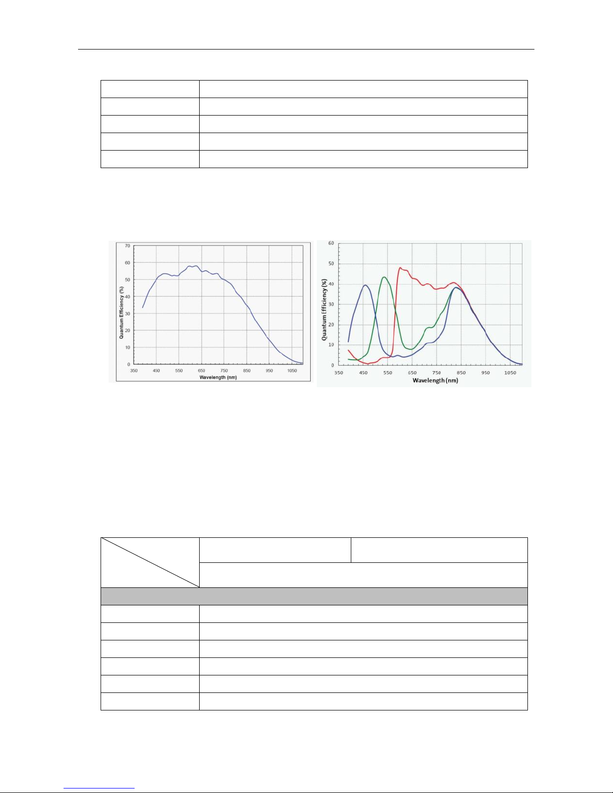
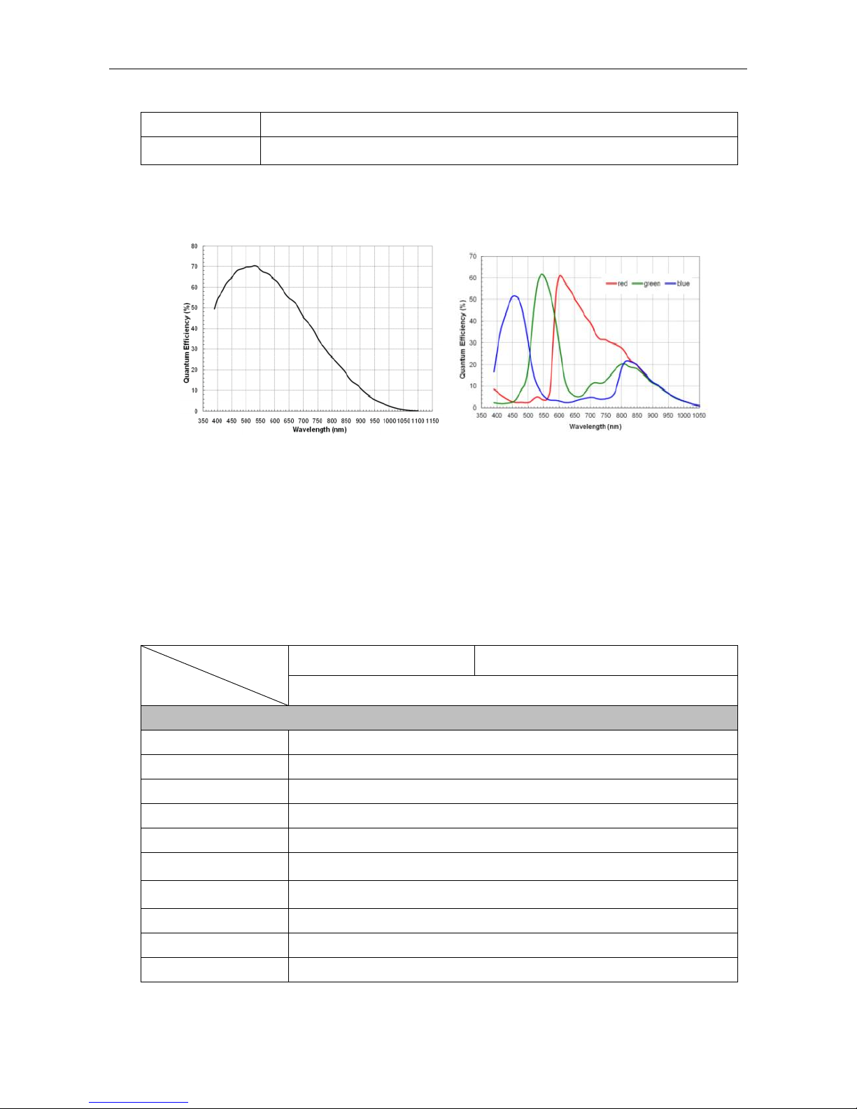
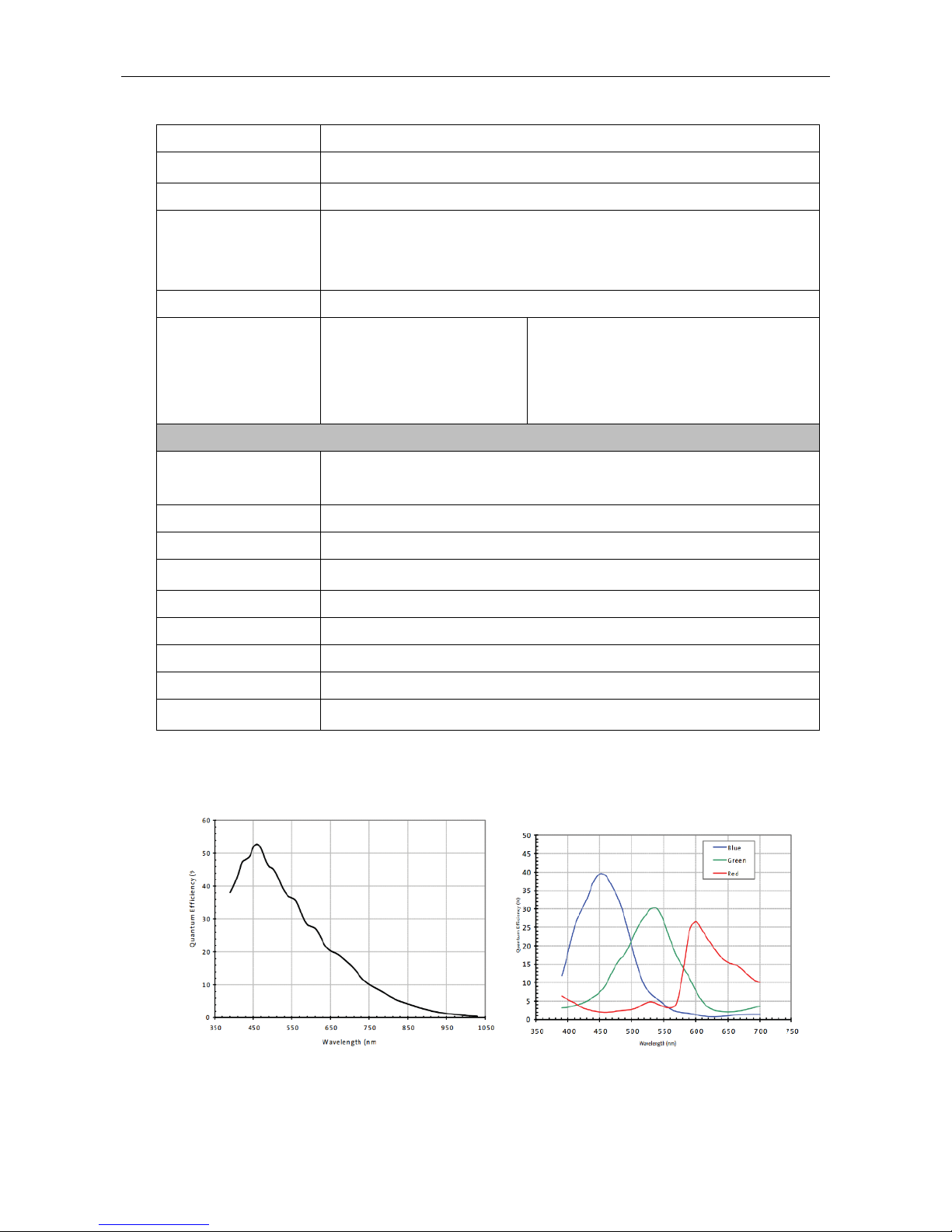
1.3.2 MV-CA003-30GM/GC Response Curve
MV-CA003-30GM Quantum Efficiency MV-CA003-30GC Quantum Efficiency
Figure 1-1 MV-CA003-30GM/GC Response Curve
Note: The response curve data is provided by the chip manufacturer.
1.3.3 MV-CA013-20GM/GC Specification
Table 1-2 Specification of MV-CA013-20GM
Model
Parameters
MV-CA013-20GM
MV-CA013-20GC
1.3 MP 1/2" CMOS Machine Vision GigE Camera
Camera
Sensor Type
PYTHON 1300
Sensor Size
1/2”
Resolution
1280×1024
Pixel Size
4.8μm
Frame Rate
90fps
Dynamic Range
>60dB
Page 12

User Manual of Area Scan GigE Camera
12
SNR
>40dB
Gain
0-15dB
Exposure Time
10μs-10sec
Shutter Mode
Global shutter, supporting Auto, Manual, One-Push, etc. exposture modes.
Data Interface
Gigabit Ethernet
Digital I/O
Opto-isolated input x 1
Opto-isolated output x 1
Bi-directional non-isolated I/O x 1
Image Buffer
128MB
Data Format
Mono 8/10/10p/12/12p
Mono 8/10/12
Bayer BG 8/10/10p/12/12p
YUV 422 8, YUV 422 8 UYVY
RGB8
General
Power Supply and
Consumption
<2.6W@12VDC or PoE, voltage 5 to 15V
Temprature
Working Temprature 0°C to 50°C, Storage Temprature -30°C to 70°C
Dimension
29mm×29mm×42mm
Weight
≈90g
Lens Mount
C-Mount
Control Client
MVS or the third-party client software which supports GigE Vision protocol
OS
Windows XP/7/8 32/64bits
Compatibility
GigE Vision V1.2
Certifications
CE, FCC, and RoHS
Page 13
User Manual of Area Scan GigE Camera
13
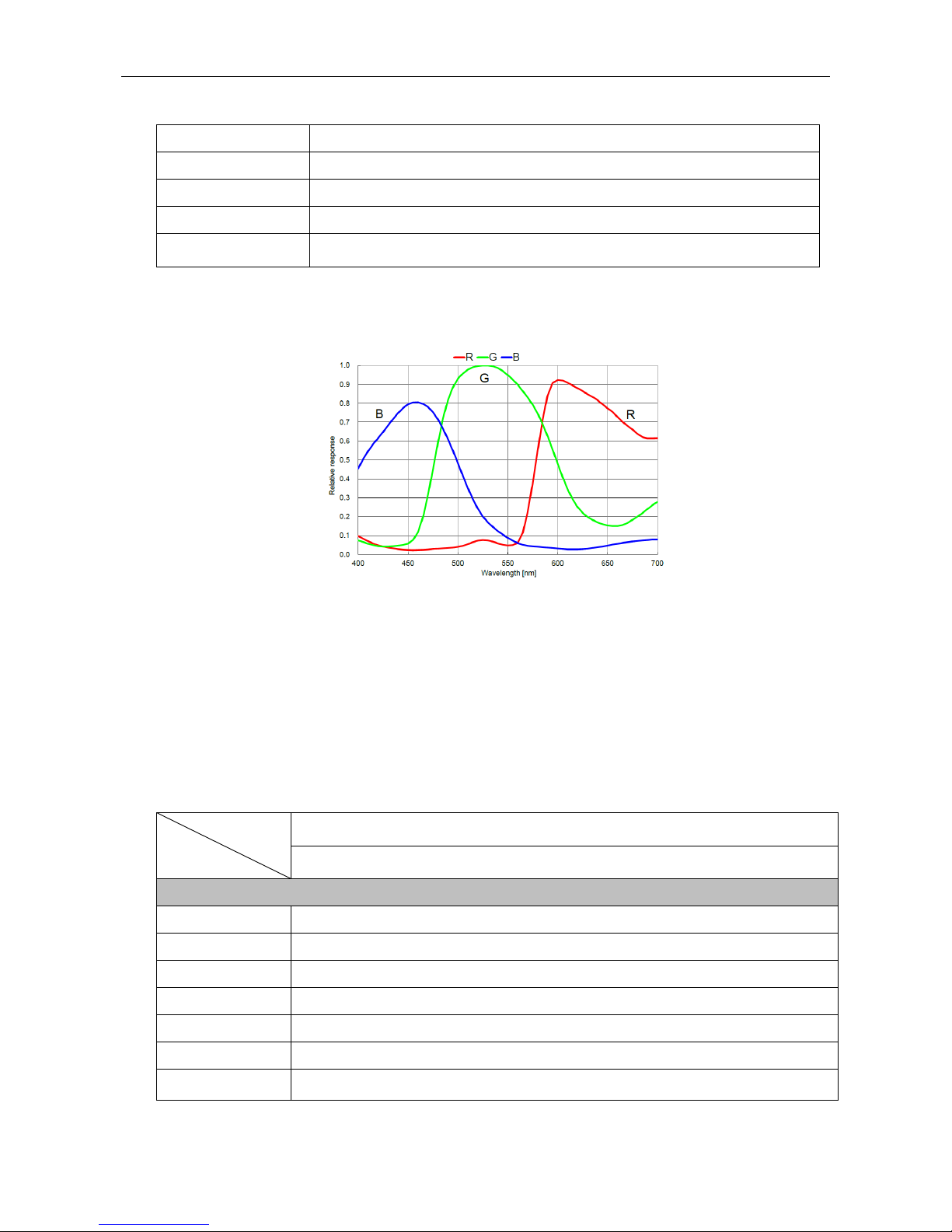
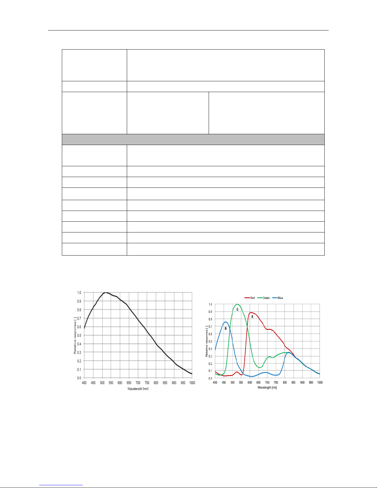
1.3.4 MV-CA013-20GM/GC Response Curve
MV -CA013-20GM Quantum Efficiency MV-CA013-20GC Quantum Efficiency
Figure 1-2 MV-CA013-20GM/GC Response Curve
Note: The response curve data is provided by the chip manufacturer.
1.3.5 MV-CA013-30GM/GC Specification
Model
Parameter
MV-CA013-30GM
MV-CA013-30GC
1.3MP 1/3" CMOS Machine Vision GigE Camera
Camera
Sensor Type
AR0134
Sensor Size
1/3”
Resolution
1280×960
Pixel Size
3.75μm
Frame Rate
53fps
Dynamic Range
>60dB
SNR
>37dB
Gain
0-15dB
Exposure Time
19μs-1sec
Shutter Mode
Global shutter, supporting Auto, Manual, One-Push, etc. exposture modes.
Data Interface
Gigabit Ethernet
Digital I/O
Opto-isolated input x 1
Opto-isolated output x 1
Bi-directional non-isolated I/O x 1
Page 14
User Manual of Area Scan GigE Camera
14
Image Buffer
128MB
Data Format
Mono 8/10/10p/12/12p
Mono8/10/12
Bayer GR 8/10/10p/12/12p
YUV422 8 YUV 422 8 UYVY
RGB8
General
Power Supply and
Consumption
<2.5W@12VDC or PoE, voltage 5 to 15V
Temprature
Working Temprature 0°C to 50°C, Storage Temprature -30°C to 70°C
Dimension
29mm×29mm×42mm
Weight
≈68g
Lens Mount
C-Mount
Control Client
MVS or the third-party client software which supports GigE Vision protocol
OS
Windows XP/7/8 32/64bits
Compatibility
GigE Vision
Certifications
CE, FCC, RoHS
1.3.6 MV-CA013-30GM/GC Response Curve
MV-CA013-30GM Quantum Efficiency MV-CA013-30GC Quantum Efficiency
Figure 1-3 MV-CA013-30GM/GC Response Curve
Note: The response curve data is provided by the chip manufacturer.
Page 15

User Manual of Area Scan GigE Camera
15
1.3.7 MV-CA030-10GM/GC Specification
Table 1-3 Specification of MV-CA030-10GM/GC
Model
Parameters
MV-CA030-10GM
MV-CA013-30GC
3 MP 1/1.8" CCD Machine Vision GigE Camera
Camera
Sensor Type
ICX687
Sensor Size
1/1.8”
Resolution
1920×1440
Pixel Size
3.69 μm
Frame Rate
25fps
Dynamic Range
>61dB
SNR
>40dB
Gain
0-20dB
Exposure Time
26μs-10sec
Shutter Mode
Global shutter, supporting Auto, Manual, One-Push, etc. exposture modes.
Data Interface
Gigabit Ethernet
Digital I/O
Opto-isolated input x 1
Opto-isolated output x 1
Image Buffer
128MB
Data Format
Mono 8/10/10p/12/12p
Mono8/10/12
Bayer GB 8/10/10p/12/12p
YUV422 8, YUV422 8 UYVY
RGB8
General
Power Supply and
Consumption
<4W@12VDC or PoE
Temprature
Working Temprature 0°C to 50°C, Storage Temprature -30°C to 70°C
Dimension
44mm×29mm×60mm
Weight
≈86g
Lens Mount
C-Mount
Control Client
MVS or the third-party client software which supports GigE Vision protocol
OS
Windows XP/7/8 32/64bits
Compatibility
GigE Vision
Page 16
User Manual of Area Scan GigE Camera
16
Certifications
CE, FCC, and RoHS
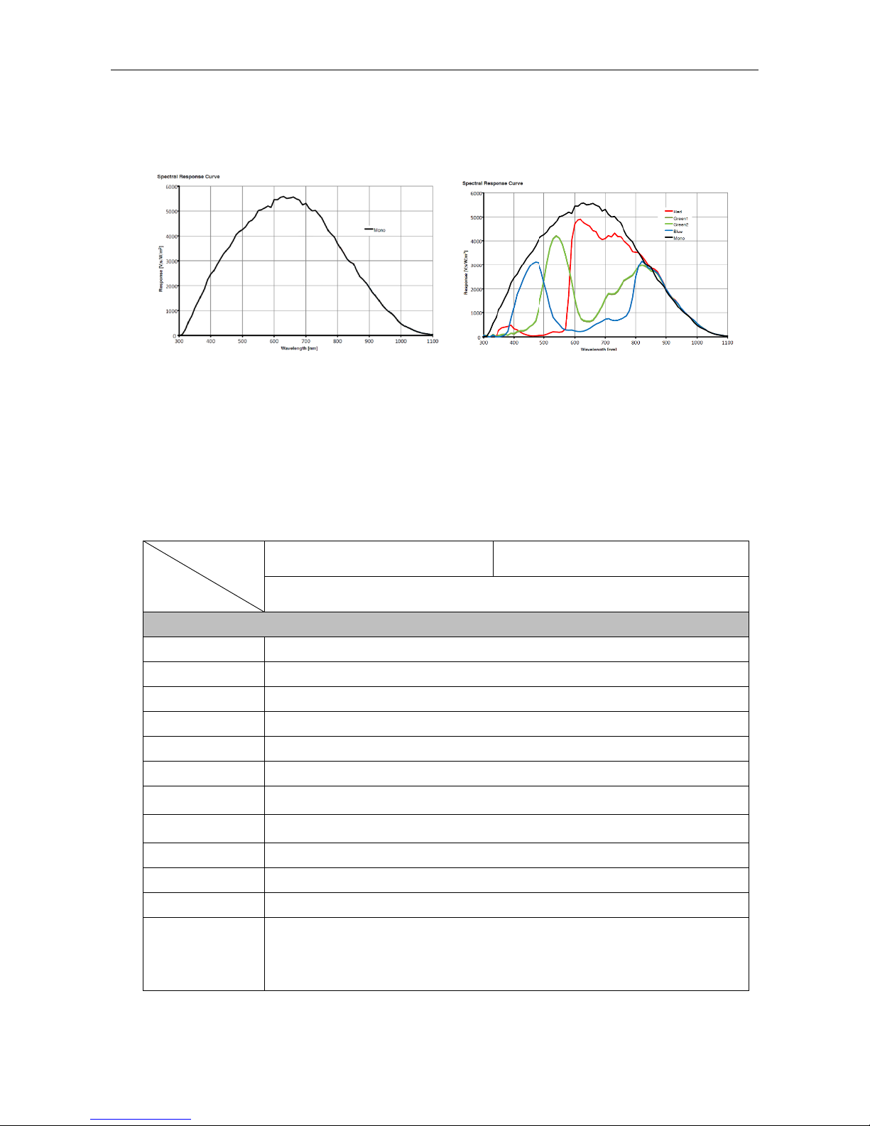
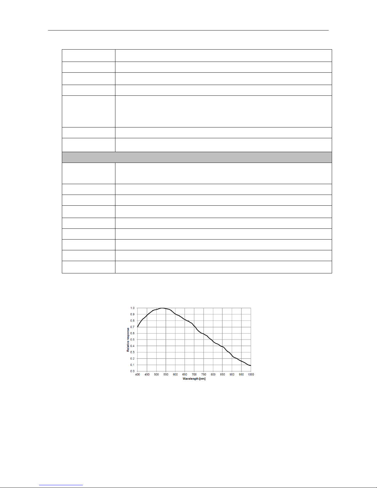
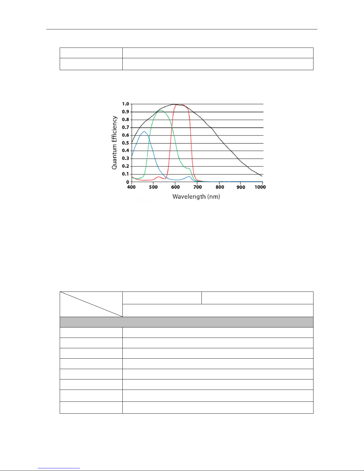
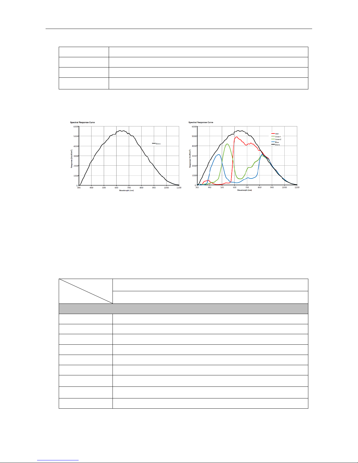
1.3.8 MV-CA030-10GM/GC Response Curve
MV-CA030-10GM Spectral Response MV-CA030-10GC Spectral Response
Figure 1-4 MV-CA030-10GM/GC Response Curve
Note: The response curve data is provided by the chip manufacturer.
1.3.9 MV-CA050-20GM/GC Specification
Table 1-4 Specification of MV-CA050-20GM/GC
Model
Parameters
MV-CA050-20GM
MV-CA050-20GC
5MP 1" CMOS Machine Vision GigE Camera
Camera
Sensor Type
PYTHON 5000
Sensor Size
1”
Resolution
2592×2048
Pixel Size
4.8μm
Frame Rate
22fps
Dynamic Range
>60dB
SNR
>40dB
Page 17
User Manual of Area Scan GigE Camera
17
Gain
0-15dB
0-10dB
Exposure Time
10μs-10sec
Shutter Mode
Global shutter, supporting Auto, Manual, One-Push, etc. exposture modes.
Data Interface
Gigabit Ethernet
Digital I/O
Opto-isolated input x 1
Opto-isolated output x 1
Bi-directional non-isolated I/O x 1
Image Buffer
128MB
Data Format
Mono 8/10/10p/12/12p
Mono8/10/12
Bayer BG 8/10/10p/12/12p
YUV422 8, YUV422 8 UYVY
RGB8
General
Power Supply and
Consumption
<3.3W@12VDC or PoE, voltage 5 to 15V
Temprature
Working Temprature 0°C to 50°C, Storage Temprature -30°C to 70°C
Dimension
29mm×29mm×42mm
Weight
≈68g
Lens Mount
C-Mount
Control Client
MVS or the third-party client software which supports GigE Vision protocol
OS
Windows XP/7/8 32/64bits
Compatibility
GigE Vision
Certifications
CE, FCC, and RoHS
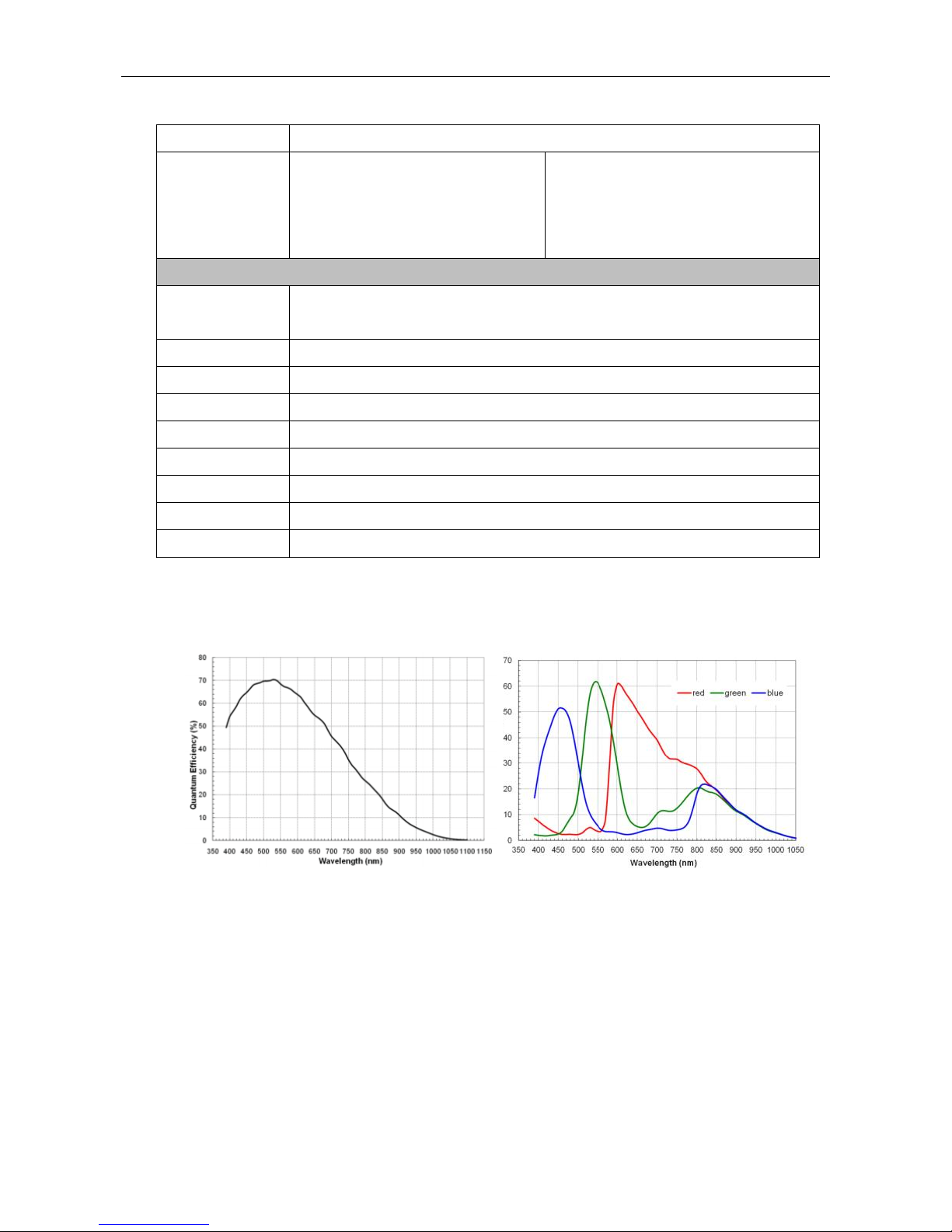
1.3.10 MV-CA050-20GM/GC Response Curve
MV-CA050-20GM Quantum Efficiency MV-CA050-20GC Quantum Efficiency
Figure 1-5 MV-CA050-20GM/GC Response Curve
Page 18
User Manual of Area Scan GigE Camera
18
Note: The response curve data is provided by the chip manufacturer.
1.3.11 MV-CA060-10GC Specification
Table 1-5 Specification of MV-CA060-10GC
Model
Parameters
MV-CA060-10GC
6MP 1/1.8" CMOS Machine Vision GigE Camera
Camera
Sensor Type
IMX178
Sensor Size
1/1.8”
Resolution
3072×2048
Pixel Size
4.8 μm
Frame Rate
17fps
Dynamic Range
>65dB
SNR
>40dB
Gain
0-20dB
Exposure Time
27μs-2.5sec
Shutter Mode
Rolling shutter, supporting Auto, Manual, One-Push, etc. exposture modes.
Data Interface
Gigabit Ethernet
Digital I/O
Opto-isolated input x 1
Opto-isolated output x 1
Bi-directional non-isolated I/O x 1
Image Buffer
128MB
Data Format
Mono8/10/12
Bayer RG 8/10/10p/12/12p
YUV422 8,YUV 422 8 UYVY
RGB8
General
Power Supply and
Consumption
<3.5W@12VDC or PoE, voltage 5 to 15V
Temprature
Working Temprature 0°C to 50°C, Storage Temprature -30°C to 70°C
Dimension
29mm×29mm×42mm
Weight
≈68g
Page 19
User Manual of Area Scan GigE Camera
19
Lens Mount
C-Mount
Control Client
MVS or the third-party client software which supports GigE Vision protocol
OS
Windows XP/7/8 32/64bits
Compatibility
GigE Vision
Certifications
CE,FCC,RoHS
1.3.12 MV-CA060-10GC Response Curve
Figure 1-6 MV-CA060-10GC Response Curve
Note: The response curve data is provided by the chip manufacturer.
1.3.13 MV-CA060-11GM Specification
Table 1-6 MV-CA060-11GM Specification
Model
Parameters
MV-CA060-11GM
6 MP 1/3" CMOS Machine Vision GigE Camera
Camera
Sensor Type
IMX178
Sensor Size
1/1.8”
Resolution
3072×2048
Pixel Size
2.4μm
Frame Rate
17fps
Dynamic Range
>65dB
SNR
>40dB
Page 20
User Manual of Area Scan GigE Camera
20
Gain
0-20dB
Exposure Time
27μs-2.5sec
Shutter Mode
rolling shutter,supporting Auto, Manual, One-Push, etc. exposture modes.
Data Interface
Gigabit Ethernet
Digital I/O
Opto-isolated input x 1
Opto-isolated output x 1
Bi-directional non-isolated I/O x 1
Image Buffer
128MB
Data Format
Mono 8/10/10p/12/12p
General
Power Supply and
Consumption
<3.5W@12VDC or PoE, voltage 5 to 15V
Temprature
Working Temprature 0°C to 50°C, Storage Temprature -30°C to 70°C
Dimension
29mm×29mm×42mm
Weight
≈68g
Lens Mount
C-Mount
Control Client
MVS or the third-party client software which supports GigE Vision protocol
OS
Windows XP/7/8 32/64bits
Compatibility
GigE Vision
Certifications
CE,FCC,RoHS
1.3.14 MV-CA060-11GM Response Curve
Figure 1-7 MV-CA060-11GM Response Curve
Note: The response curve data is provided by the chip manufacturer.
Page 21
User Manual of Area Scan GigE Camera
21
1.3.15 MV-CA003-50GM/GC Specification
Table 1-7 MV-CA003-50GM/GC Specification
Model
Parameters
MV-CA003-50GM
MV-CA003-50GC
0.3 MP 1/3" CCD Machine Vision GigE Camera
Camera
Sensor Type
RJ33B4AD0DT
Sensor Size
1/3”
Resolution
640×480
Pixel Size
7.4μm
Frame Rate
200fps@
Dynamic Range
>52dB
SNR
>37dB
Gain
0-20dB
Exposure Time
20μs-1sec
Shutter Mode
Global shutter, supporting Auto, Manual, One-Push, etc. exposture modes.
Data Interface
Gigabit Ethernet
Digital I/O
Opto-isolated input x 1
Opto-isolated output x 1
Bi-directional non-isolated I/O x 1
Image Buffer
128MB
Data Format
Mono 8/10/10p/12/12p
Mono 8/10/12
Bayer GB 8/10/10p/12/12p
YUV 422 8,YUV 422 8 UYVY
RGB8
General
Power Supply and
Consumption
≈3.6W@12VDC or PoE, voltage 5 to 15V
Temprature
Working Temprature 0°C to 50°C, Storage Temprature -30°C to 70°C
Dimension
29mm×29mm×42mm
Weight
≈68g
Lens Mount
C-Mount
Control Client
MVS or the third-party client software which supports GigE Vision protocol
OS
Windows XP/7/8 32/64bits
Page 22
User Manual of Area Scan GigE Camera
22
Compatibility
GigE Vision
Certifications
CE,FCC,RoHS
1.3.16 MV-CA003-50GM/GC Response Curve
MV-CA003-50GM Quantum Efficiency MV-CA003-50GC Quantum Efficiency
Figure 1-8 MV-CA003-50GM/GC Response Curve
Note: The response curve data is provided by the chip manufacturer.
1.3.17 MV-CA023-10GM/GC Specification
Table 1-8 MV-CA023-10GM/GC Specification
Model
Parameter
MV-CA023-10GM
MV-CA023-10GC
2.3 MP 1/1.2" CMOS Machine Vision GigE Camera
Camera
Sensor Type
IMX249
Resolution
1920×1200
Pixel Size
5.86μm
Frame Rate
30fps
Dynamic Range
>70dB
SNR
>40dB
Gain
0-20dB
Exposure Time
26μs-0.1sec
Shutter Mode
Global shutter, supporting Auto, Manual, One-Push, etc. exposture modes.
Data Interface
Gigabit Ethernet
Page 23
User Manual of Area Scan GigE Camera
23
Digital I/O
Opto-isolated input x 1
Opto-isolated output x 1
Bi-directional non-isolated I/O x 1
Image Buffer
128MB
Data Format
Mono 8/10/10p/12/12p
Mono 8/10/12
Bayer RG 8/10/10p/12/12p
YUV 422 8,YUV 422 8 UYVY
RGB8
General
Power Supply and
Consumption
≈3W@12VDC or PoE, voltage 5 to 15V
Temprature
Working Temprature 0°C to 50°C, Storage Temprature -30°C to 70°C
Dimension
29mm×29mm×42mm
Weight
≈68g
Lens Mount
C-Mount
Control Client
MVS or the third-party client software which supports GigE Vision protocol
OS
Windows XP/7/8 32/64bits
Compatibility
GigE Vision
Certifications
CE,FCC,RoHS
1.3.18 MV-CA023-10GM/GC Response Curve
MV-CA023-10GM Quantum Efficiency MV-CA023-10GC Quantum Efficiency
Figure 1-9 MV-CA023-10GM/GC Response Curve
Note: The response curve data is provided by the chip manufacturer.
Page 24
User Manual of Area Scan GigE Camera
24
1.3.19 MV-CA050-10GM/GC Specification
Table 1-9 MV-CA050-10GM/GC Specification
Model
Parameter
MV-CA050-10GM
MV-CA050-10GC
5 MP 2/3" CMOS Machine Vision GigE Camera
Camera
Sensor Type
IMX264
Sensor Size
2/3”
Resolution
2448×2048
Pixel Size
3.45μm
Frame Rate
23.5fps
Dynamic Range
>60dB
SNR
>40dB
Gain
0-17dB
Exposure Time
20μs-10sec
Shutter Mode
Global shutter, supporting Auto, Manual, One-Push, etc. exposture modes.
Data Interface
Gigabit Ethernet
Digital I/O
Opto-isolated input x 1
Opto-isolated output x 1
Bi-directional non-isolated I/O x 1
Image Buffer
128MB
Data Format
Mono 8/10/10p/12/12p
Mono 8/10/12
Bayer RG 8/10/10p/12/12p
YUV 422 8,YUV 422 8 UYVY
RGB8
General
Power Supply and
Consumption
≈3.3W@12VDC or PoE, voltage 5 to 15V
Temprature
Working Temprature 0°C to 50°C, Storage Temprature -30°C to 70°C
Dimension
29mm×29mm×42mm
Weight
≈68g
Lens Mount
C-Mount
Control Client
MVS or the third-party client software which supports GigE Vision protocol
OS
Windows XP/7/8 32/64bits
Page 25
User Manual of Area Scan GigE Camera
25
Compatibility
GigE Vision
Certifications
CE,FCC,RoHS
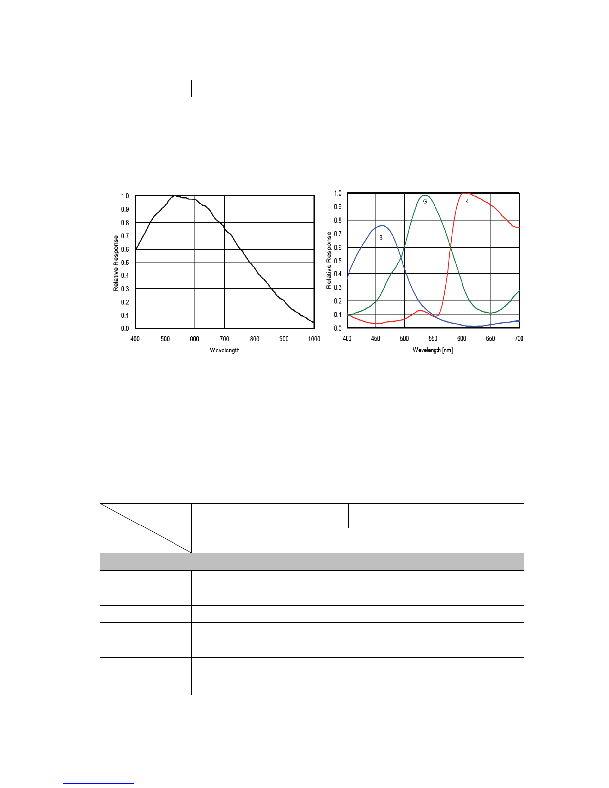
1.3.20 MV-CA050-10GM/GC Response Curve
MV-CA050-10GM/GC Quantum Efficiency
Figure 1-10 MV-CA050-10GM/GC Response Curve
Note: The response curve data is provided by the chip manufacturer.
1.3.21 MV-CE100-30GM/GC Specification
Table 1-10 MV-CE100-30GM/GC Specification
Model
Parameter
MV-CE100-30GM
MV-CE100-50GC
10 MP 1/2.3" CMOS Machine Vision GigE Camera
Camera
Sensor Type
MT9J003
Sensor Size
1/2.3”
Resolution
3840×2748
Pixel Size
1.67μm
Frame Rate
7fps
Dynamic Range
>65dB
SNR
>34dB
Gain
0-15.3dB
Page 26
User Manual of Area Scan GigE Camera
26
Exposure Time
50μs-2sec
Shutter Mode
rolling shutter,supporting Auto, Manual, One-Push, etc. exposture modes.
Data Interface
Gigabit Ethernet
Digital I/O
Opto-isolated input x 1
Opto-isolated output x 1
Bi-directional non-isolated I/O x 1
Image Buffer
128MB
Data Format
Mono 8/10/10p/12/12p
Mono 8/10/12
Bayer GR 8/10/10p/12/12p
YUV 422 8,YUV 422 8 UYVY
RGB8
General
Power Supply and
Consumption
≈2.6W@12VDC or PoE, voltage 5 to 15V
Temprature
Working Temprature 0°C to 50°C, Storage Temprature -30°C to 70°C
Dimension
29mm×29mm×42mm
Weight
≈68g
Lens Mount
C-Mount
Control Client
MVS or the third-party client software which supports GigE Vision protocol
OS
Windows XP/7/8 32/64bits
Compatibility
GigE Vision
Certifications
CE,FCC,RoHS
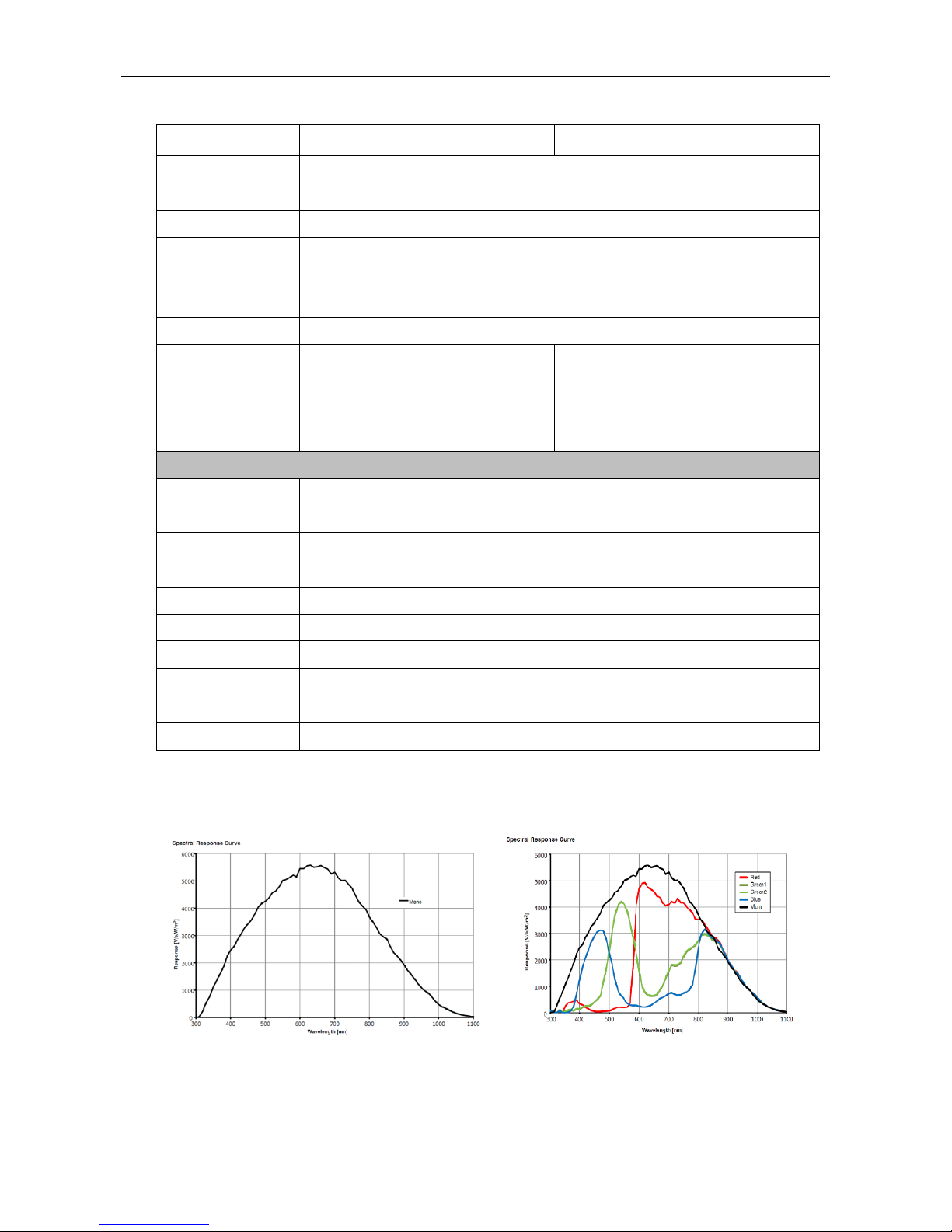
1.3.22 MV-CE100-30GM/GC Response Curve
MV-CE100-30GM Quantum Efficiency MV-CE100-30GC Quantum Efficiency
Figure 1-11 MV-CE100-30GM/GC Response Curve
Page 27

User Manual of Area Scan GigE Camera
27
Note: The response curve data is provided by the chip manufacturer.
1.3.23 MV-CA003-20GM/GC Specification
Table 1-11 MV-CA003-20GM/GC Specification
Model
Parameter
MV-CA003-20GM
MV-CA003-20GC
0.3 MP 1/4" CMOS Machine Vision GigE Camera
Camera
Sensor Type
PYTHON 300
Sensor Size
1/4”
Resolution
672×512
Pixel Size
1.67μm
Frame Rate
300fps
Dynamic Range
>60dB
SNR
>40dB
Gain
0-15dB
Exposure Time
10μs-10sec
Shutter Mode
Global shutter, supporting Auto, Manual, One-Push, etc. exposture modes.
Data Interface
Gigabit Ethernet
Digital I/O
Opto-isolated input x 1
Opto-isolated output x 1
Bi-directional non-isolated I/O x 1
Image Buffer
128MB
Data Format
Mono 8/10/10p/12/12p
Mono 8/10/12
Bayer RG 8/10/10p/12/12p
YUV 422 8,YUV 422 8 UYVY
RGB8
General
Power Supply and
Consumption
≈2.6W@12VDC or PoE, voltage 5 to 15V
Temprature
Working Temprature 0°C to 50°C, Storage Temprature -30°C to 70°C
Dimension
29mm×29mm×42mm
Weight
≈68g
Lens Mount
C-Mount
Page 28
User Manual of Area Scan GigE Camera
28
Control Client
MVS or the third-party client software which supports GigE Vision protocol
OS
Windows XP/7/8 32/64bits
Compatibility
GigE Vision V1.2
Certifications
CE,FCC,RoHS
1.3.24 MV-CA003-20GM/GC Response Curve
MV-CA003-20GM Quantum Efficiency MV-CA003-20GC Quantum Efficiency
Figure 1-12 MV-CA003-20GM/GC Response Curve
Note: The response curve data is provided by the chip manufacturer.
1.3.25 MV-CA013-20GN Specification
Table 1-12 MV-CA013-20GN Specification
Model
Parameter
MV-CA013-20GN
1.3 MP 1/2" CMOS Near-infrared enhanced Machine Vision GigE Camera
Camera
Sensor Type
PYTHON 1300
Sensor Size
1/2”
Resolution
1280×1024
Pixel Size
4.8μm
Frame Rate
90fps
Dynamic Range
>60dB
SNR
>40dB
Gain
0-15dB
Exposure Time
10μs-10sec
Page 29
User Manual of Area Scan GigE Camera
29
Shutter Mode
Global shutter, supporting Auto, Manual, One-Push, etc. exposture modes.
Data Interface
Gigabit Ethernet
Digital I/O
Opto-isolated input x 1
Opto-isolated output x 1
Bi-directional non-isolated I/O x 1
Image Buffer
128MB
Data Format
Mono 8/10/10p/12/12p
General
Power Supply and
Consumption
≈2.6W@12VDC or PoE, voltage 5 to 15V
Temprature
Working Temprature 0°C to 50°C, Storage Temprature -30°C to 70°C
Dimension
29mm×29mm×42mm
Weight
≈68g
Lens Mount
C-Mount
Control Client
MVS or the third-party client software which supports GigE Vision protocol
OS
Windows XP/7/8 32/64bits
Compatibility
GigE Vision
Certifications
CE,FCC,RoHS
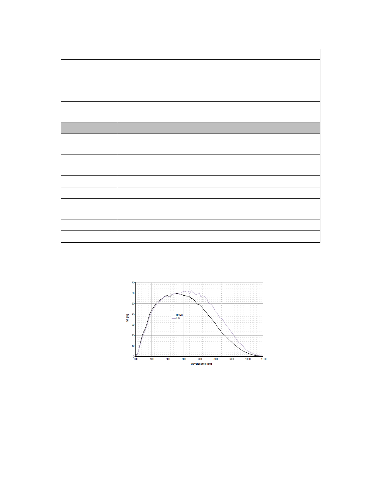
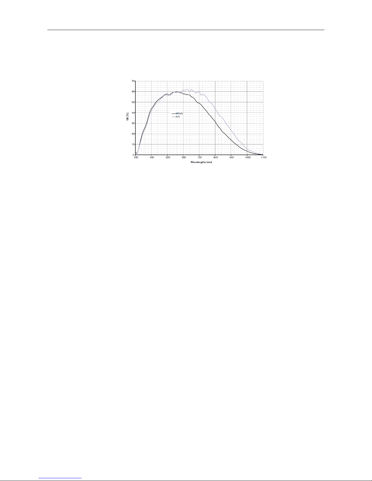
1.3.26 MV-CA013-20GN Response Curve
MV-CA013-20GN Quantum Efficiency
Figure 1-13 MV-CA013-20GN Response Curve
Note: The response curve data is provided by the chip manufacturer.
Page 30
User Manual of Area Scan GigE Camera
30
1.3.27 MV-CA050-20GN Specification
Table 1-13 MV-CA050-20GN Specification
Model
Parameter
MV-CA050-20GN
5 MP 1" CMOS Machine Vision GigE Camera
Camera
Sensor Type
PYTHON 5000
Sensor Size
1”
Resolution
2592×2048
Pixel Size
4.8μm
Frame Rate
22fps
Dynamic Range
>60dB
SNR
>40dB
Gain
0-15dB
Exposure Time
10μs-10sec
Shutter Mode
Global shutter, supporting Auto, Manual, One-Push, etc. exposture modes.
Data Interface
Gigabit Ethernet
Digital I/O
Opto-isolated input x 1
Opto-isolated output x 1
Bi-directional non-isolated I/O x 1
Image Buffer
128MB
Data Format
Mono 8/10/10p/12/12p
General
Power Supply and
Consumption
≈3.3W@12VDC or PoE, voltage 5 to 15V
Temprature
Working Temprature 0°C to 50°C, Storage Temprature -30°C to 70°C
Dimension
29mm×29mm×42mm
Weight
≈68g
Lens Mount
C-Mount
Control Client
MVS or the third-party client software which supports GigE Vision protocol
OS
Windows XP/7/8 32/64bits
Compatibility
GigE Vision
Certifications
CE,FCC,RoHS
Page 31
User Manual of Area Scan GigE Camera
31
1.3.28 MV-CA050-20GN Response Curve
MV-CA050-20GN Quantum Efficiency
Figure 1-14 MV-CA050-20GN Response Curve
Note: The response curve data is provided by the chip manufacturer.
1.4 Camera Physical Interfaces
1.4.1 Camera Dimension
The mechanical dimension of the MV-CA030-10GM/GC is shown below. The camera should be
installed with M3*3 screws.
Page 32

User Manual of Area Scan GigE Camera
32
2xM3 3
4xM3 3
26
4
60
9.5
29
44
52
4
26
Figure 1-15 Dimension of MV-CA030-10GM/GC
The mechanical dimension of the MV-CA003-30GM/GC, MV-CA013-20GM,
MV-CA013-30GM/GC, MV-CA050-20GM, MV-CA060-10GM/GC is shown below. The camera
should be installed with M3*3 or M2*3 screws.
Page 33

User Manual of Area Scan GigE Camera
33
29
29
4211.675
3-M3 3
4-M2 3
20
23.7
12
22
3
4.5
Figure 1-16 Dimension of Other Models
Note: The camera adopts the C-Mount lens interface. The flange back length of lens is
17.5mm±0.15mm.
1.4.2 Rear Panel Introduction
The rear panel of the machine vision camera is shown in the figure below.
1
2
3
4
2
1
2
3
4
2
Type I
Type II
Page 34

User Manual of Area Scan GigE Camera
34
Figure 1-17 Rear Panel
Table 1-14 Description of the Rear Panel
No.
Description
1
RJ45 gigabit Ethernet interface
2
M2 screw holes for network cable securing
3
6-pin power and I/O interface
4
Status indicator LED
1.4.3 Power and I/O Interface Introduction
The description of the 6-pin power and I/O connector is shown in the table below.
1
2
3 4
5
6
Figure 1-18 Power and I/O Interface
Table 1-15 Description
No.
Signal
I/O Type
Description
1
12V
Input
DC 12V
2
Opt-Iso In
Input
Opto-isolated input
3
GPIO
Input/output
Can be configured as input or output
4
Opt-Iso Out
Output
Opto-isolated output
5
I/O Ground
Input
Opt- isolated I/O grounding
6
GND
Input
Power and GPIO grounding
For the MV-CA030-10GM/GC camera, Pin3 is in the Not Connect status.
Page 35

User Manual of Area Scan GigE Camera
35
1.4.4 Installation Accessories
Prepare the installation accessories listed below before you install the machine vision camera.
Table 1-16 Accessory List
No.
Accessory Name
Number
Description
1
Camera
1
The machine vision camera.
2
Power I/O cable
1
The 6-pin cable (included) or extension cable (not
included).
3
Power adapter
1
12V DC power adapter (Min. 1A)
4
Ethernet cable with
proper length
1
CAT-5e or CAT-6 Ethernet cable
5
Lens (Optional)
1
C-Mount Lens
6
Mounting Bracket
(Optional)
1
The mounting bracket has four M2 holes and one
1/4-32UNF interface.
Page 36

Chapter 2 Camera
Installation and
Configuration
2.1 Installing the Camera
Steps:
1. Unpack the camera package and install the lens (optional) to the camera body
by rotating the lens clockwise.
2. Fix the camera to the desired position.
3. Use CAT-5e or CAT-6 network cable to connect the camera with a switch or a
network card.
4. Choose a power supply method.
Direct supply: Use the supplied cord with a 6-pin power and I/O interface to
connect the camera to a power adapter (DC 12V for the camera).
PoE (Power over Ethernet): Use a network cable to connect the camera to a
switch or a network card that supports PoE function.
Note: The machine vision network camera adopts a gigabit network interface. To
guarantee the bandwidth for real-time image transmission, you need to use a CAT-5e
or CAT-6 network cable.
2.2 Network Configuration
Purpose:
Before using the camera, you need to configure the IP address of the camera. The IP
addresses of the camera and the local computer should belong to the same network
segment. You can use the ping command on the local computer to test the network
connectivity.
Before you start:
Download the MVS control client from the website and install it on your PC. Refer to
Page 37

User Manual of Area Scan GigE Camera
37
the User Manual of MVS Client Software for details.
2.2.1 Local Network Configuration
Steps:
1. Click Start -> Control Panel -> Network and Internet -> Network and Sharing
Center -> Change adapter settings, select the network connection and click
Properties.
2. Double click the TCP protocol, and you can set select Obtain an IP address
automatically.
3. (Optional) You can also select Use the following IP address, and set the IP
address as the same subnet with the camera.
Figure 2-1 IP Address Setting
4. Click OK to save the settings.
5. You also need to enable the jumbo frame of the NIC. For different operating
Page 38

User Manual of Area Scan GigE Camera
38
systems, the path to setting the jumbo frame may be different. Here we take
Windows 7 as an example.
1) Click Start -> Control Panel -> Hardware and Sound -> Device Manager ->
Network adapters, double click the NIC to enter its properties interface.
2) Click Advanced tab.
3) Select Jumbo Frame from the property list and select the value as 9KB
MTU.
4) Click OK to save the settings.
Note: Jumbo frame is not supported by some types of NIC. We recommend you to use
the NIC which supports jumbo frame for better image transmission.
2.2.2 Camera IP Configuration
You can use the client software to complete network configuration for the camera.
Steps:
1. Double click the “MVS IP Configurator.exe” to open the configuration tool.
You can find the tool in the installation directory.
2. Select the camera to configure.
Figure 2-2 Camera Network Parameters Setting (1)
Page 39
User Manual of Area Scan GigE Camera
39
3. You can view the camera status and modify the settings.
If the camera status is Free, the camera is available and you can edit its IP
address.
If the camera status is In Use, it means the client software or other processes
are accessing the camera. You need to stop the live view and disconnect the
camera, or terminate other processes to access the camera.
If the camera status is Not Reachable, the network of the camera is
exceptional and you should check the camera network settings.
Note: The camera status may be In Use if the camera IP address is conflicted with
other device. Please make sure the IP address is not occupied before setting the
camera IP address.
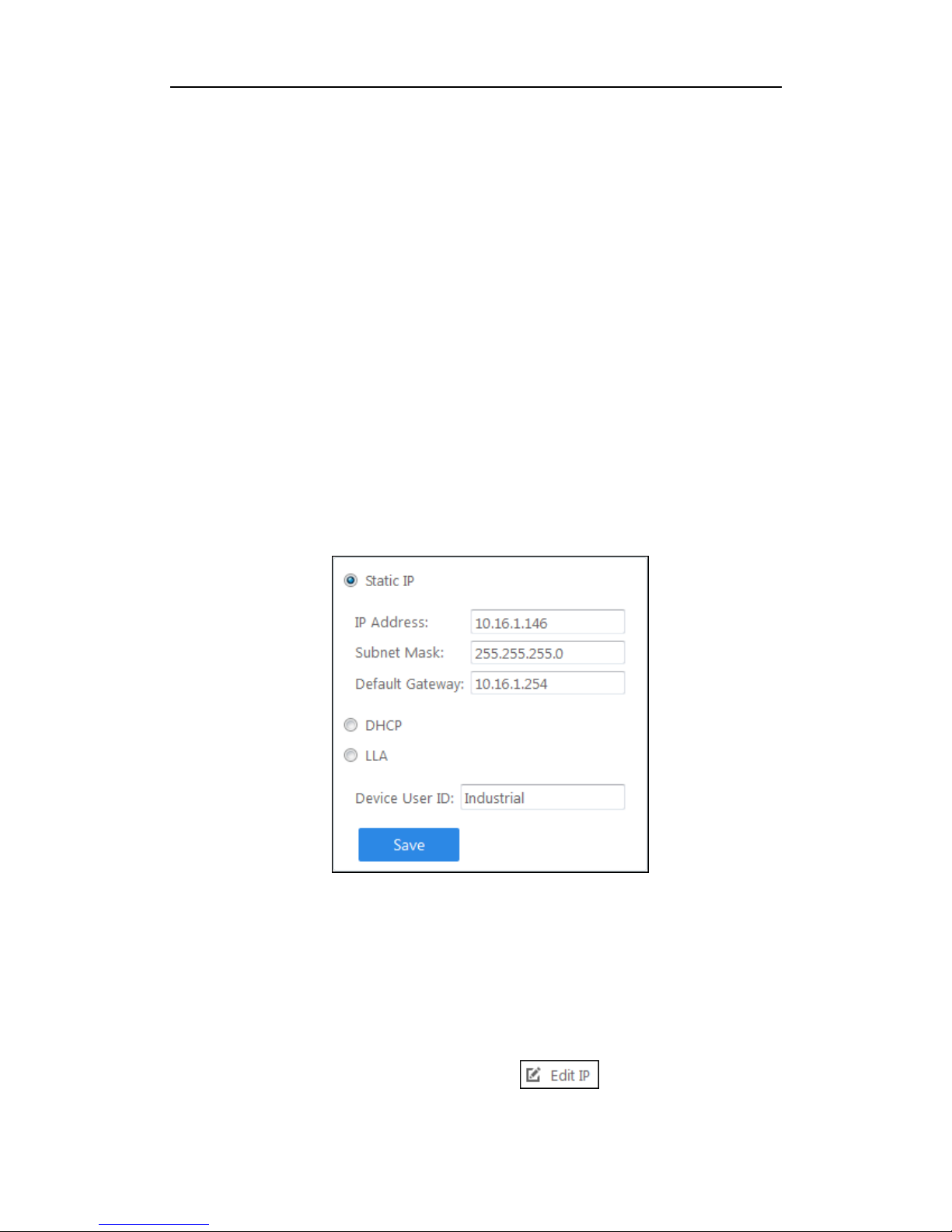
4. If the camera status is Free, you can edit its IP address.
1) Select the IP type as Static IP, DHCP, or LLA.
Figure 2-3 Camera Network Parameters Setting (2)
If you set the IP type as Static IP, you can set the IP address, subnet mask, and default
gateway.
You can also edit the the camera name in Device User ID field.
Click Save to save the settings.
2) Select the camera to be edited and click button.
Page 40

User Manual of Area Scan GigE Camera
40
3) In the pop-up window, you can edit the IP address of the camera. For Static
IP type, you can also edit the subnet mask and default gateway.
Figure 2-4 Camera Network Parameters Setting (3)
4) Click OK to save the settings.
2.3 Camera Configuration
Note: Configure the camera via the control client. There two methods available: setting via the
attribute tree or via the menu bar.
2.3.1 Setting via Attribute Tree
The software can read the XML file of camera attributes and display it in tree format.
Steps:
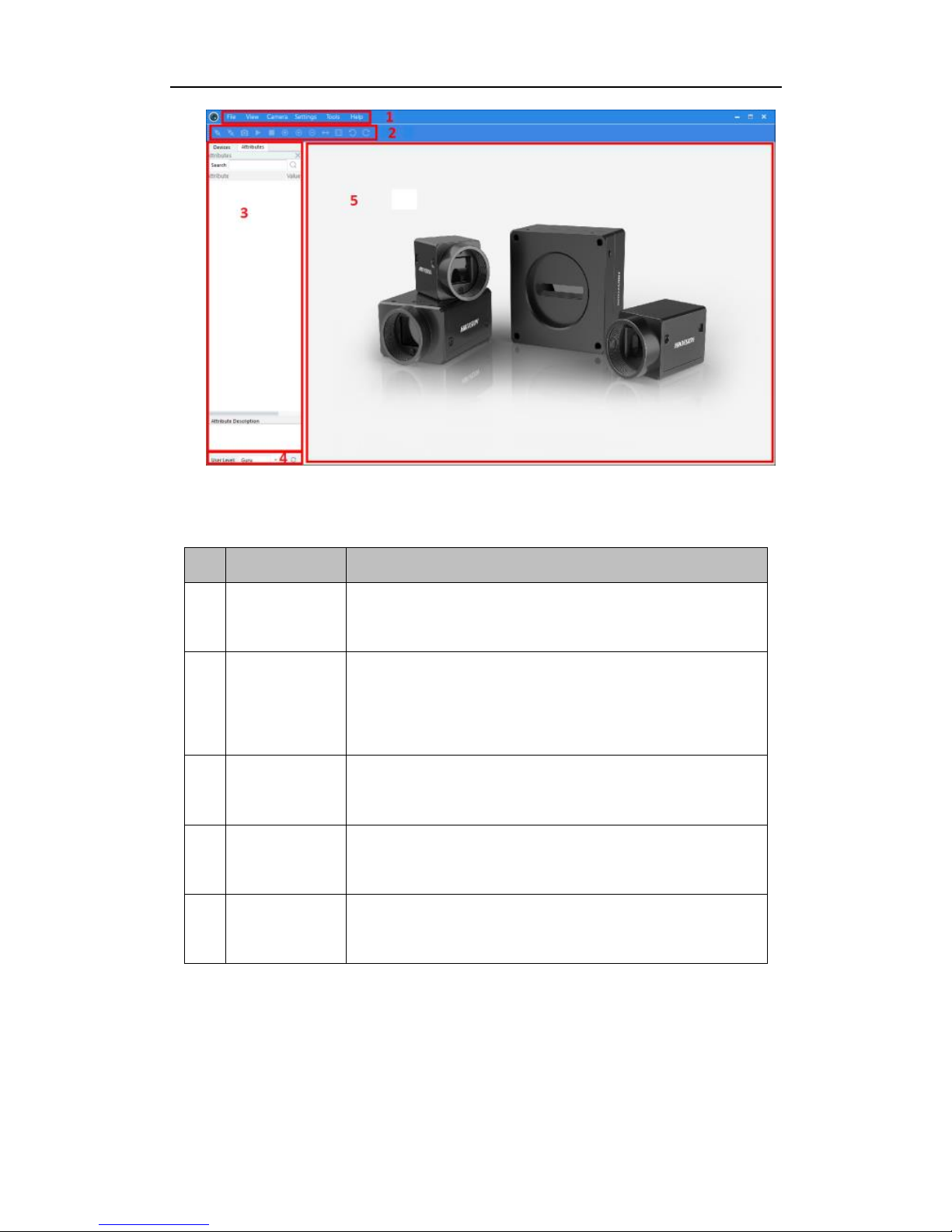
1. Double click the MVS icon to open the client software. The main user
interface and the description of the client software are shown in Figure 2-5 and
Table 2-1.
Page 41
User Manual of Area Scan GigE Camera
41
Figure 2-5 Main User Interface of the Client Software
Table 2-1 Description of the Main User Interface
No.
Area Name
Description
1
Menu Bar
Function modules including File, View, Camera,
Settings, Tools, and Help.
2
Control
Toolbar
Contorl the image of live view including
starting/stopping live view, zooming in/out, recording,
capturing, etc.
3
Device and
Attribute Tree
Display the online machine vision cameras in the same
LAN with the client software and the device attributes.
4
User Level
Area
Switch the user level quickly as beginner, expert or guru.
5
Live View
Area
View the live video of the selected machine vision
camera.
Note: For detailed information, refer the User Manual of MVS Control Client.
2. Double click the camera on the device list in Device and Attribute Tree area.
3. Click the Attributes tab to enter the camera attribute page.
Note: You can switch the user level as Beginner, Expert or Guru which displays
Page 42
User Manual of Area Scan GigE Camera
42
different camera attributes. For Guru Level, it provides the most comprehensive
camera attributes for professional use. Here we take Guru Level as an example.
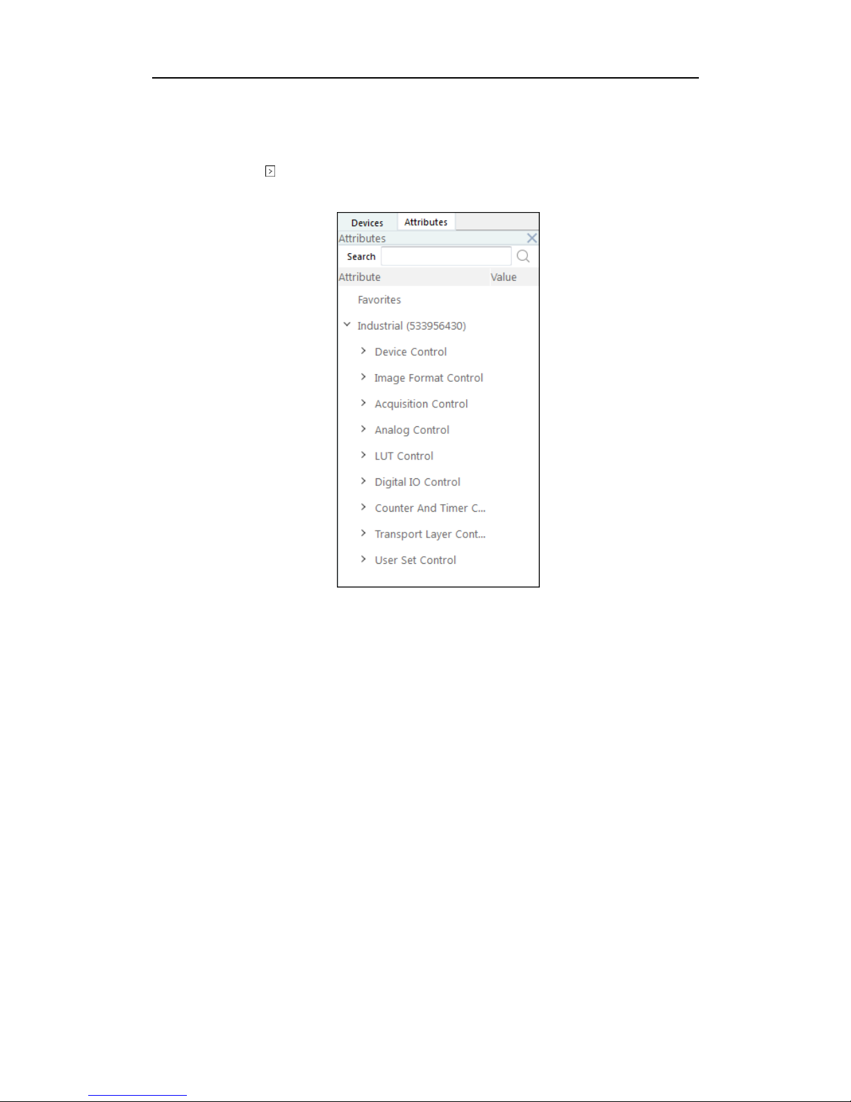
4. Click the icon before each attribute to view and edit the details.
Figure 2-6 Attribute Page
Device Control: In the Device Control attribute, you can view the camera details
include device type, version, manufacturer details, device ID, device alias,
device temperature, etc. You can modify the alias and reset the device.
Image Format Control: In the Image Format Control attribute, you can view the
live view image width and height, pixel size, etc. You can modify the image
reverse status, test pattern and the embedded information, etc.
Acquisition Control: In the Acquisition Control attribute, you can set the trigger
mode, trigger source, exposure details, etc.
Analog Control: In the Analog Control attribute, you can adjust analog gain,
black level, brightness, gamma, sharpness, AOI, etc.
LUT Control: In the LUT Control attribute, you can view the user lookup table
and set the LUT index and value.
Page 43
User Manual of Area Scan GigE Camera
43
Digital IO Control: In the Digital IO Control attribute, you can manage the digital
input and output.
Counter and Timer Control: In the Counter and Timer Control attribute, you can
set the counter and timer function. It can count the triggering signal and control
the exposure according to the user needs.
Transport Layer Control: In the Transport Layer Control attribute, you can set the
parameters of transport layer of the camera.
User Set Control: In the User Set Control attribute, you can save or load the
parameter configuration set by users. You can set the default parameter when
running the software.
2.3.2 Setting via Menu Bar
You can set the camera attribute via the menu bar which classifies the camera
attributes.
Click Settings -> Attributes to enter the attributes setting interface.
Page 44

User Manual of Area Scan GigE Camera
44
Figure 2-7 Setting via Menu Bar
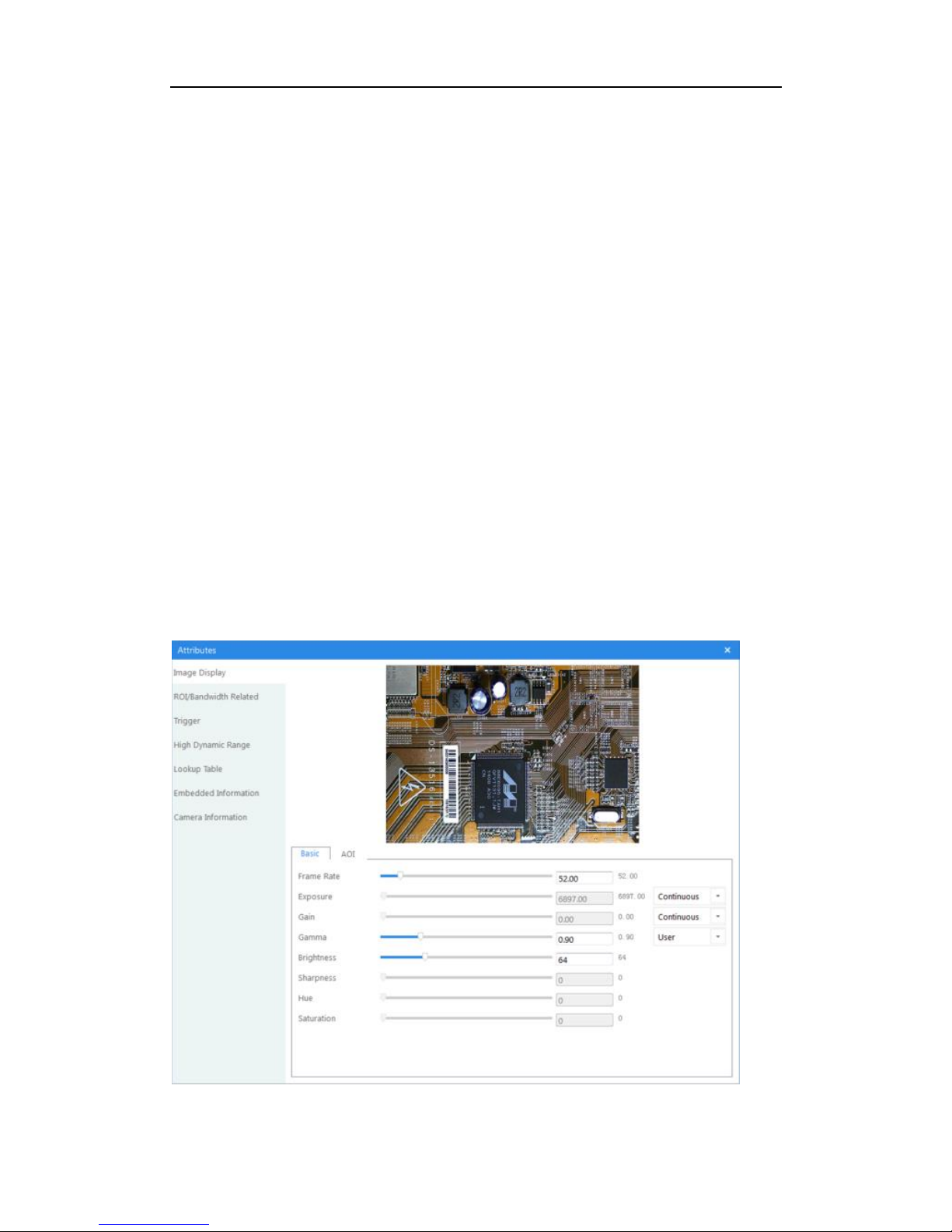
You can set the image display, ROI, bandwidth, trigger mode, high dynamic range,
lookup table, embedded information and camera information.
Note: Functions and Attributes of machine vision cameras may be different among
different camera models. Refer to the actual user interface and the user manual of the
camera for detailed information.
Page 45

User Manual of Area Scan GigE Camera
45
Chapter 3 Functions
3.1 Device Control
3.1.1 Name Modification
Run client software and click Device Control. You will see the device type, the
version information, the device serial number and so on. Input the device name in
Device User ID as shown in Figure 3-1.
Figure 3-1 Device Name Modification
You can turn on the heartbeat detection mechanism, reset the device and view the
device temperature in Device Control, as shown in Figure 3-2.
Page 46

User Manual of Area Scan GigE Camera
46
Figure 3-2 Device Information
3.2 Image Format and Frame Rate
Support different image format and customized ROI setting. The specified ROI will
increase the image frame rate in some models.
Note: The following figures are for reference only. The actual format depends on the
camera’s supported formats.
3.2.1 Camera Data Format
The supporting pixel format of MV-CA camera is shown in Table 3-1.
Table 3-1 Data Format Table
Format
Mono8
Mono
10/10p
Mono12/
12p
RGB
8
Bayer
8
Bayer
10/10p
Bayer
12/12
p
YUV
422
YUV 422
(UYVY)
MV-CA003-30GM
Y Y ---
---
---
---
---
---
---
MV-CA003-30GC
Y
---
--- Y BG
BG
--- Y Y
MV-CA013-20GM
Y Y ---
---
---
---
---
---
---
MV-CA013-30GM
Y Y Y
---
---
---
---
---
---
MV-CA013-30GC
Y
---
--- Y GR
GR
GR Y Y
MV-CA030-10GM
Y Y Y
---
---
---
---
---
---
Page 47

User Manual of Area Scan GigE Camera
47
MV-CA030-10GC
Y
---
--- Y GB
---
GB Y Y
MV-CA050-20GM
Y Y ---
---
---
---
---
---
---
MV-CA060-10GM
Y Y ---
---
---
---
---
---
---
MV-CA060-10GC
Y
---
--- Y RG
RG
RG Y Y
Note: YUV 422 8 is the default output data format for color camera. Mono8 is the
default output format for black and white camera. “Y” means support and “---” means
not support.
Color camera changes from the original data to RGB8 by color interpolation
algorithm. Bayer GB, Bayer GR and any other patterns are shown in the following
four figures.
Figure 3-3 Bayer GR Pixel Pattern
Figure 3-4 Bayer GB Pixel Pattern
Figure 3-5 Bayer BG Pixel Pattern
Figure 3-6 Bayer RG Pixel Pattern
Page 48
User Manual of Area Scan GigE Camera
48
The camera uses 12 bit ADC (some only support 10 bit ADC). Support 8 bit data
output according to your data processing capacity.
The camera will capture 8 bit from Most Significant Bits just as MSB8 output, in
order to maintain the grey level output of the image data.
The bytes number corresponding to different formats are shown in Table 3-2.
Table 3-2 Pixel Format
Pixel Format
Byte Number
Mono 8, Bayer GB/GR/BG/RG 8
1
Bayer GR/GB/RG 12 Packed, Bayer BG/GR/RG 10
Packed, Mono10 Packed, Mono12 packed
1.5
Bayer GR/GB/RG 12, Bayer BG/GR/RG 10, YUV
4:2:2 (YUYV), YUV4:2:2 (YUYV) Packed
2
RGB 8
3
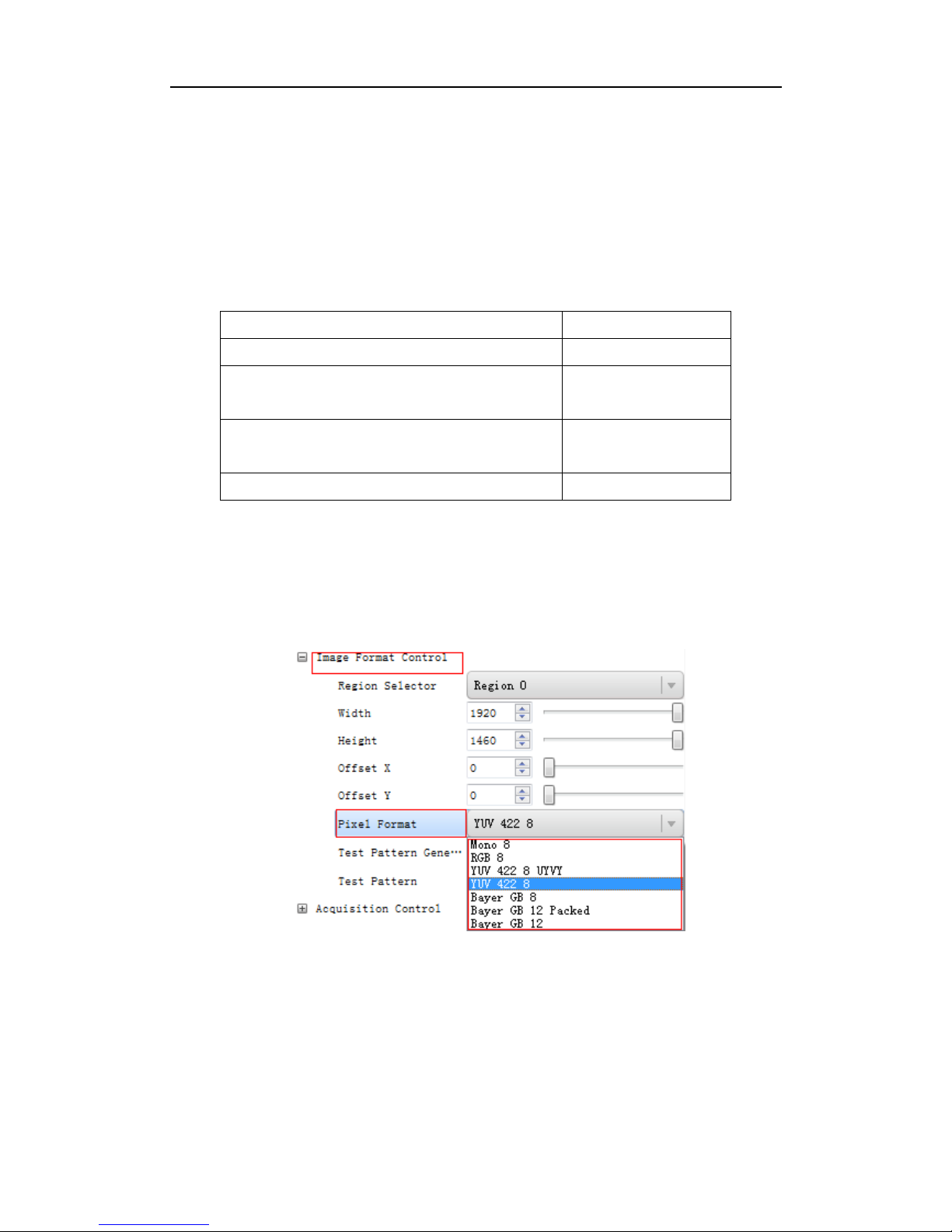
Click Image Format Control in the attribute list and select Pixel Format. You will find
the supported pixel format. Choose the appropriate data output format as shown in
Figure 3-7 and finish setting.
Figure 3-7 Frame Rate Setting
Page 49

User Manual of Area Scan GigE Camera
49
3.2.2 Frame Rate
The network transmission bandwidth, pixel format and output ROI resolution decides
the maximum camera frame rate. Please refer to the frame rate formula when setting
ROI.
Click Acquisition Control in the attribute list and select Acquisition Frame Rate. Input
available frame rate as shown in Figure 3-8 and finish setting.
Figure 3-8 Frame Rate Setting
3.2.3 ROI Setting
The following three factors decide the maximum camera frame rate:
Frame Readout time: the shorter the image height, the less the readout time and
the higher the frame rate.
Exposure time: the less the exposure time, the higher the frame rate.
Bandwidth: the wider the bandwidth, the higher the frame rate.
The camera can output ROI images depending on your requires. ROI setting can
decrease the data transmission bandwidth and increase the camera frame rate. The
following formulas show the frame rate corresponding to the ROI:
Fps1 = 1/(ROI height * T1 + ROI OffsetY * T2 + T3);
Page 50

User Manual of Area Scan GigE Camera
50
Fps2 = 1/Exp Time;
Fps3 = Bandwidth / PayloadSize;
Table 3-3 ROI and Frame Rate Parameter Table
Value
Model
T1(us)
T2(us)
T3(us)
MV-CA003-30GM/GC
31.33
0
1410.15
MV-CA013-20GM
11.06
0
375.89
MV-CA013-30GM/GC
18.69
0
691.66
MV-CA030-10GM/GC
25.83
4.31
2273.33
MV-CA050-20GM
18.77
0
150.19
MV-CA060-10GM/GC
17.82
0
1493.3
The lowest frame rate within the three formulas is Resulting Frame Rate.
Click Image Format Control and move. Select Width and Height. Adjust the ROI on
the right side. The value in the Offset X and the Offset Y refer to the ROI starting
point at the top left corner. The following figure shows the ROI setting.
Figure 3-9 ROI Setting
Note: For more information about bandwidth and Payload Size, please see the chapter
of Transmission Layer Control.
Page 51

User Manual of Area Scan GigE Camera
51
3.3 Global Shutter and Rolling Shutter
3.3.1 Global Shutter
Support global shutter camera. Exposure starts and ends in each line simultaneously.
Data readout is after the exposure. The time for the sensor collecting exposure and for
the data readout are the same, but as shown in Figure 3-10, different in the actual
readout time.
Line 1
Line 2
Line 3
Line 4
Line 5
Line n
Line n-1
Readout
Readout
Exposure
Figure 3-10 Global Shutter
3.3.2 Rolling Shutter
Support rolling shutter camera. The exposure starts in the first row, and the data will
read out simultaneously. After the whole action, the rest of rows start to expose and
read out one by one. The time for the sensor collecting exposure and for the data
readout are the same, but as shown in Figure 3-11, different in the exposure starting
time.
Page 52

User Manual of Area Scan GigE Camera
52
Line 1
Line 2
Line 3
Line 4
Line 5
Line n
Line n-1
Readout
Readout
Exposure
Offset=Readout
Figure 3-11 Rolling Shutter
The figure of rolling shutter’s signal readout under internal trigger mode
Sensor
exposure
Intergration1 Intergration2 Intergration3
Frame 1
Readout
Frame 2
Readout
Figure 3-12 Internal Trigger Mode
The figure of rolling shutter’s signal readout under the external trigger mode
Page 53

User Manual of Area Scan GigE Camera
53
Trigger_in1
Sensor
exposure
Intergration
1
Intergration
2
Trigger delay
Trigger_in2
Trigger delay
Frame time Frame time
Frame1
Readout
Frame2
Readout
Figure 3-13 External Trigger Mode
3.4 Image Acquisition and Transmission
Image acquisition mode is divided into internal trigger mode and external trigger
mode. Internal trigger mode includes continuous acquisition mode and single frame
acquisition mode. External trigger mode includes software trigger mode and hardware
external trigger mode.
Select On or Off in Trigger Mode to select either internal trigger mode or external
trigger mode. (Off refers to the internal trigger mode and On refers to the external
trigger mode.)
3.4.1 Internal Trigger Mode
The Camera can output one image or several images continuously in the internal
trigger mode.
Click Acquisition Control in the attribute list. Select Acquisition Mode and you will
see elements of Continuous and SingleFrame. Continuous refers to outputting images
Page 54

User Manual of Area Scan GigE Camera
54
continuously based on the configured frame rate. SingleFrame refers to outputting
only one image, as shown in Figure 3-14.
Figure 3-14 Internal Trigger Mode
3.4.2 External Trigger Signal and Working Mode
The signal for the camera to acquire external trigger signal includes the software
trigger signal and the signal from external level.
Under the external trigger signal mode, the camera can output images according to
single frame mode, burst mode, PWM mode and any other working modes.
Software trigger mode
Support software trigger mode. When setting software trigger mode, the client
software will send command to the camera to capture and transfer images by gigabit
network.
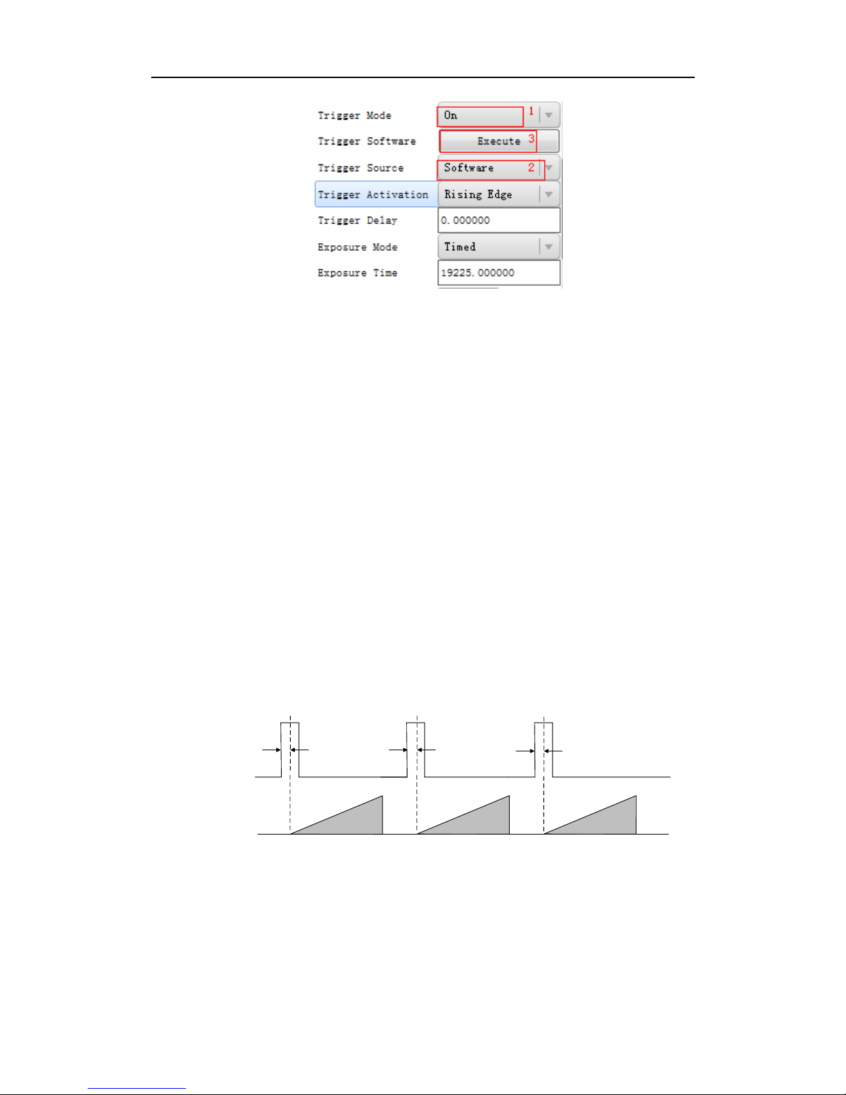
Click Acquisition Control in the attribute list and select Trigger Mode. Choose On to
open trigger mode. Select Trigger Source and choose Software to switch to the
software external trigger status. Click Execute in Trigger Software to trigger image
acquisition, as shown in Figure 3-15.
Page 55
User Manual of Area Scan GigE Camera
55
Figure 3-15 Software Trigger Mode Setting
Hardware external trigger mode
Select Trigger Source and Choose Hardware to switch to the hardware external trigger
status.
Available parameter setting of input signal from hardware external trigger:
(1) Trigger edge selection
Selecting Rising Edge/Falling Edge under the external signal is available.
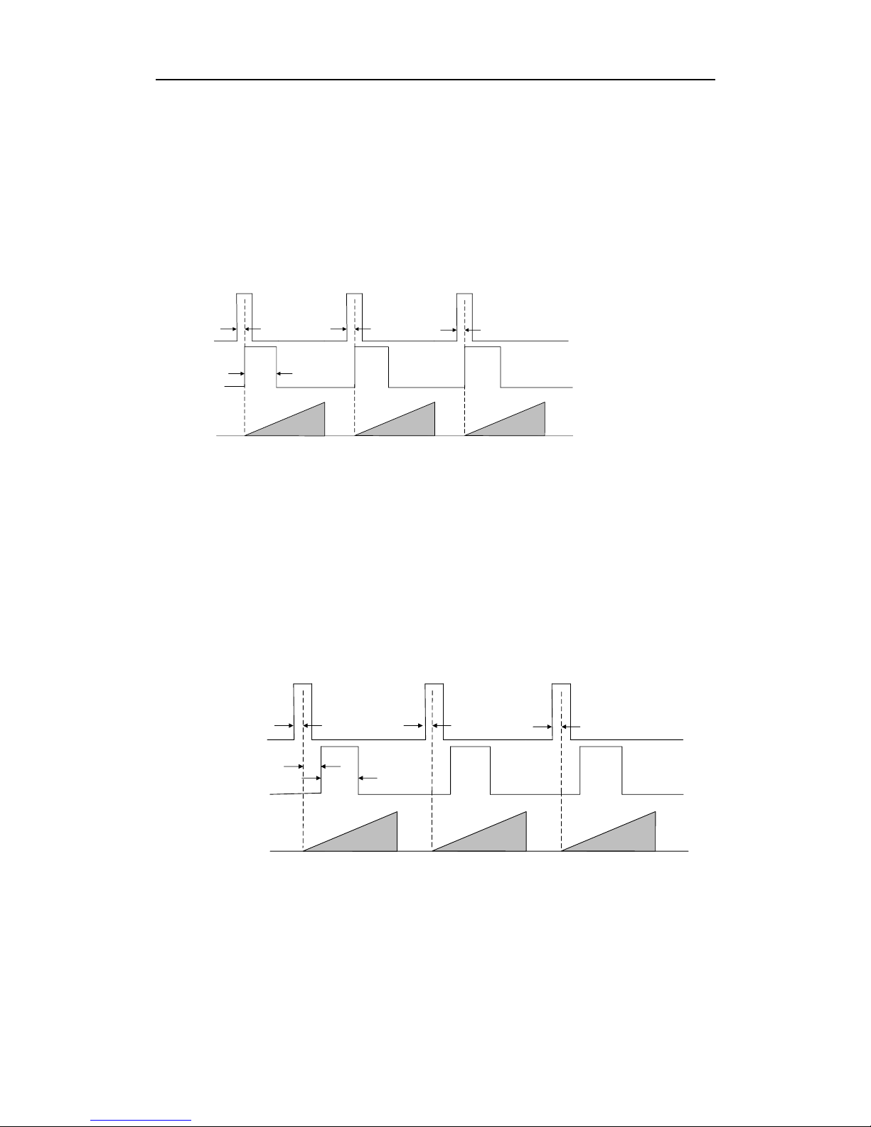
(2) Trigger delay
As shown in Figure 3-16, in order to integrate later, the camera can set delay time
when receiving the trigger signal. As shown in Figure 3-17, the delay time can be set
through Trigger Delay. The range is from 0 to 32000000 and the unit is μs.
Sensor
exposure
Intergration1 Intergration2 Intergration3
Trigger_in1
Trigger
delay
Trigger_in2
Trigger
delay
Trigger_in3
Trigger
delay
Figure 3-16 Signal Delay Principle
Page 56

User Manual of Area Scan GigE Camera
56
Figure 3-17 Delay Time Setting
(3) Triggering Anti-jitter
The noise may exist in external trigger’s input signal and it may cause spurious
triggering status if it goes into the camera. Thus the debounce is necessary.
The debounce parameter can be set through Line Debouncer Time in the client
software. The unit is μs. The timing sequence map is shown in Figure 3-18. The
camera will ignore the trigger signal if the debouncer time is longer than the
triggering signal time.
Trigger_in1 Trigger_in2 Trigger_in3
Trigger_in2 Trigger_in3
Before
debounce
After
debounce
Debouncer Time Debouncer Time
Figure 3-18 The Debounce of Triggering Input Signal Sequence Map
3.5 Strobe Output
Strobe is external trigger output signal and is used for controlling external devices
such as flashing light and so on. You can set the Strobe polarity, duration, output delay
Page 57

User Manual of Area Scan GigE Camera
57
and pre-trigger through the client software.
As shown in Figure 3-19, click Digital IO Control. Select Line Selector and choose
output pin. Check Strobe Enabled and finish setting.
Figure 3-19 Strobe Output Mode
Available Strobe parameter setting:
(1) Polarity setting
Tick Line Inverter to set polarity external trigger’s output signal, as shown in Figure
3-20.
Figure 3-20 Modifying Strobe Polarity
Page 58
User Manual of Area Scan GigE Camera
58
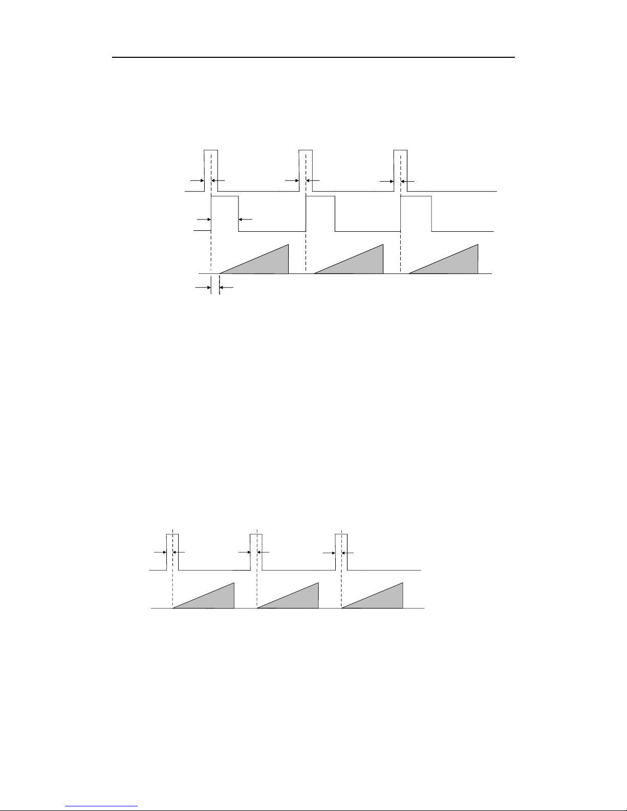
(2) Strobe valid time
As shown in Figure 3-21, Strobe is set to high level. When exposure starts, Strobe will
output immediately. Strobe Line Duration value decides the Strobe duration: when the
Strobe Line Duration value is 0, the Strobe duration is equal to the exposure time;
when the Strobe Line Duration value is not 0, the Strobe duration is equal to Strobe
Line Duration value.
Strobe
Trigger_in1
Sensor
exposure
Intergration1 Intergration2 Intergration3
Trigger
delay
Trigger_in2
Trigger
delay
Trigger_in3
Trigger
delay
Duration
Figure 3-21 Strobe Valid Electrical Level Duration
(3) Strobe output delay
The camera supports the function of Strobe signal output delay to satisfy special
application: as shown in Figure 3-22, when exposure starts, the Strobe output is not
valid immediately. Instead, the Strobe output will delay according to the setting in
Strobe Line Delay.
Strobe
Trigger_in1
Sensor
exposure
Intergration1 Intergration2 Intergration3
Strobe
delay
Trigger_in2
Trigger
delay
Trigger_in3
Trigger
delay
Duration
Trigger
delay
Figure 3-22 Strobe Output Delay Sequence Map
(4) Strobe pre-trigger
Support Strobe pre-trigger. Strobe signal is valid before the sensor exposure. This
Page 59
User Manual of Area Scan GigE Camera
59
function can apply to the LED light that takes time to be stable after starting. It is
necessary for a stable light source when capturing images. Pre-trigger time can be set
through Strobe Line Pre Delay in the client as shown in Figure 3-23.
Strobe
Trigger_in1
Sensor
exposure
Intergration1 Intergration2 Intergration3
Trigger
delay
Trigger_in2
Trigger
delay
Trigger_in3
Trigger
delay
Duration
Strobe pre delay
Figure 3-23 Strobe Pre-trigger Sequence Map
3.6 Acquisition Mode under External Trigger
The acquisition mode under external trigger includes single frame mode, burst mode
and PWM mode. The relationship among the input trigger signal, the Strobe output
signal, the exposure time and readout time under different modes is as follows:
(1) Single frame mode
Expose only once when inputting one trigger signal.
Sensor
exposure
Intergration1 Intergration2 Intergration3
Trigger_in1
Trigger
delay
Trigger_in2
Trigger
delay
Trigger_in3
Trigger
delay
Figure 3-24 Single Frame Mode
The frame rate and exposure time decide to trigger the next frame or not when reading
out camera data. If exposure is in progress, the camera will ignore another external
trigger signal. You can set a longer exposure time to achieve Bulb Shutter.
Page 60

User Manual of Area Scan GigE Camera
60
(2) Burst mode
The camera supports burst mode: receiving one trigger signal and outputting multiply
frames images. You can set the burst number by Acquisition Burst Frame Count in the
client software. The range is from 0 to 1023. The sequence map is shown in Figure
3-25. If Burst Frame Count = 3, one trigger signal will output three frames images and
at the same time output three strobe signals.
Strobe
Trigger_in1
Sensor
exposure
Intergration1 Intergration2 Intergration3
Trigger
delay
Duration
Figure 3-25 Burst Mode Sequence Map
(3) PWM mode
Support PWM mode. The difference in the sensor’s exposure time is the main
difference between the PWM mode and the single frame mode. In the PWM mode,
the duration of trigger source decides the sensor’s exposure time of each frame. The
sequence map is shown in Figure 3-26.
Strobe
Trigger_in1
Sensor
exposure
Intergration1 Intergration2 Intergration3
Trigger
delay
Trigger_in2
Trigger_in3
Duration
Trigger
delay
Trigger
delay
Figure 3-26 PWM Mode Sequence Map
Page 61

User Manual of Area Scan GigE Camera
61
Note: Only the camera of MV-CA030-10GM/GC supports PWM mode.
3.7 Overlap Exposure and Non-overlap Exposure
To capture one frame of image includes the exposure and the readout. According to
the overlap relationship between the exposure time and the readout time, cameras
with different chips can be divided into overlap exposure and non-overlap exposure.
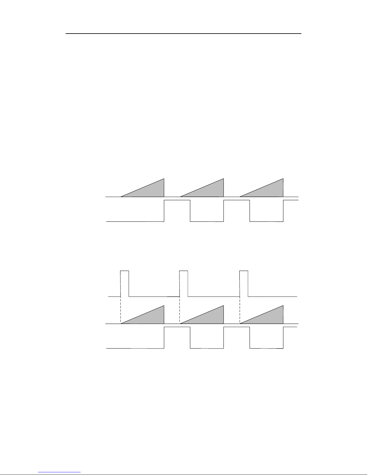
3.7.1 Non-overlap Exposure
After completing the current frame’s exposure and readout, the next frame starts to
expose and read out. This process is called non-overlap exposure. The non-overlap
exposure’s frame period is larger than the sum of the exposure time and the readout
time as shown in Figure 3-27and Figure 3-28.
Non-overlap exposure under internal trigger mode
Sensor
exposure
Intergration1
Intergration2
Intergration3
Frame 1
Readout
Frame 2
Readout
Figure 3-27 Internal Mon-overlap Exposure
Non-overlap exposure under external trigger mode
Trigger_in1
Trigger_in2 Trigger_in3
Sensor
exposure
Intergration1
Intergration2
Intergration3
Frame 1
Readout
Frame 2
Readout
Page 62
User Manual of Area Scan GigE Camera
62
Figure 3-28 External Non-overlap Exposure
The camera will ignore the receiving external signal in the readout section under this
mode.
3.7.2 Overlap Exposure
Overlap exposure refers to the overlap between the current frame exposure and the
last frame readout. In other words, when the last frame starts to read out, the current
frame starts to expose simultaneously.
Overlap exposure under internal trigger mode
Sensor
exposure
Intergration1 Intergration2 Intergration3
Frame 1
Readout
Frame 2
Readout
Figure 3-29 Internal Trigger Overlap Exposure
Overlap exposure under external trigger mode
Sensor
exposure
Intergration1 Intergration2 Intergration3
Trigger_in1 Trigger_in2 Trigger_in3
Frame 1
Readout
Frame 2
Readout
Figure 3-30 External Trigger Overlap Exposure
Note: Cameras of MV-CA003-30GM/GC, MV-CA013-30GM/GC,
MV-CA060-10GM/GC do not support overlap exposure under external trigger mode.
Page 63
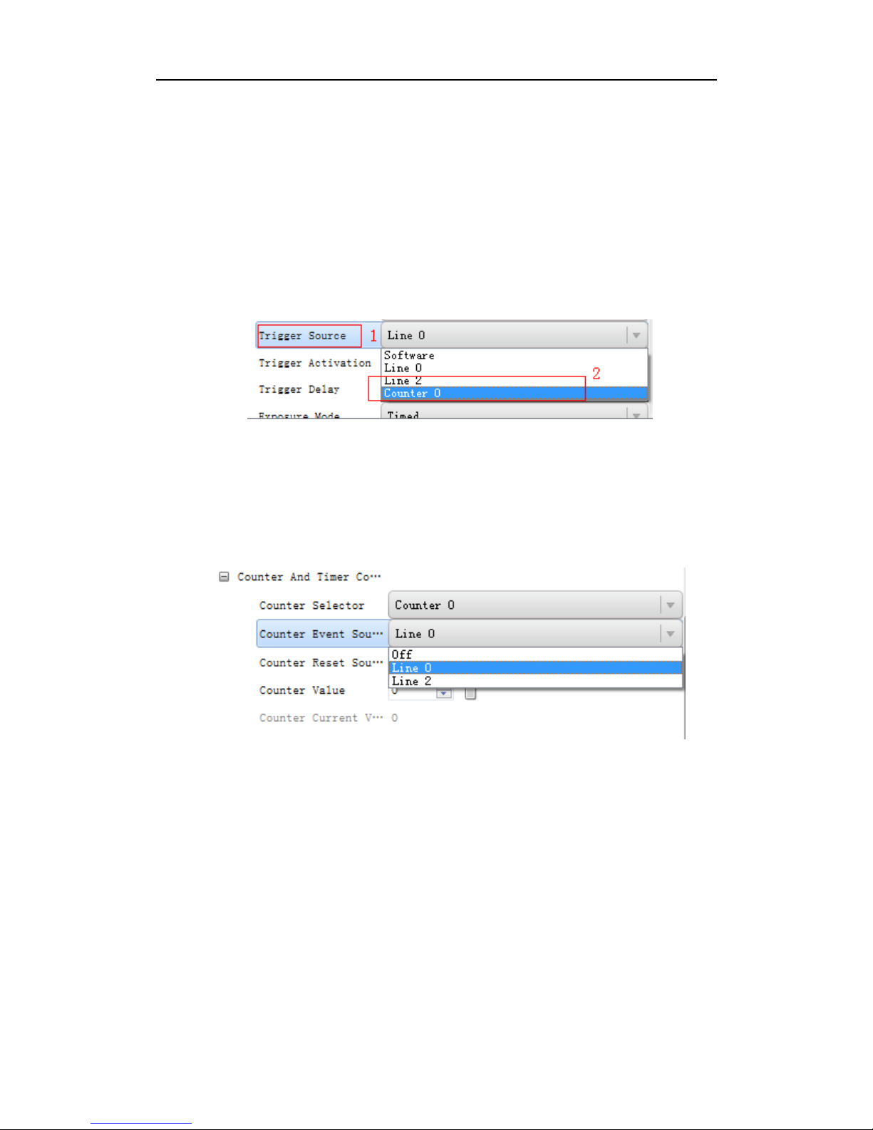
User Manual of Area Scan GigE Camera
63
3.8 Counter Control
The counter can divide frequencies that from external inputting trigger signal. You can
control the exposure depends on your expectations. Operation steps are as follows:
As shown in Figure 3-31, click Acquisition Burst Frame Count and select Trigger
Source. Choose Counter 0.
Figure 3-31 Trigger Source Configuration
As shown in Figure 3-32, click Counter And Timer Control and select external trigger
source which needs frequency division.
Figure 3-32 Counter Frequency Division Configuration
Note: By default, Line 0 is signal input pin. Line 2 is configurable input and output
pin. Configure Line 2 to input pin in Digital IO Control, as shown in Figure 3-33, in
order to do frequency division for Line 2.
Page 64

User Manual of Area Scan GigE Camera
64
Figure 3-33 Configuring Line 2 Pin to Input
In Counter And Timer Control, you should set Counter Value. Parameter value range
is from 1 to 1023. Please see the red 2 in Figure 3-34.
Figure 3-34 Counter Parameter Setting
By default, Counter Reset Source is OFF as shown in the red 1 in Figure 3-34. Click
Counter And Timer Control and select Counter Reset Source. Choose Software and
click Execute to reset the counter, as shown in Figure 3-35.
Figure 3-35 Resetting The Counter
Page 65

User Manual of Area Scan GigE Camera
65
3.9 Imaging Parameter Setting
3.9.1 Exposure Time
Please refer to the camera technical index to acquire the supported exposure time. The
exposure control supports manual mode, single mode and continuous mode. When
setting trigger mode, the single mode and continuous mode are invalid. When setting
single mode or continuous mode, the exposure time will be limited by Auto Exposure
Time Lower Limit and Auto Exposure Time Upper Limit. The time range should only
be set between Auto Exposure Time Lower Limit and Auto Exposure Time Upper
Limit.
Click Acquisition Control in the attribute list. Select Auto Exposure Time Lower
Limit and Auto Exposure Time Upper Limit. Input available parameter to the numeric
field. Set the running parameter range of the auto exposure time, as shown in Figure
3-36.
Figure 3-36 Exposure Control
3.9.2 Gain Control
Please refer to the camera technical index to acquire the supported Gain Value. Gain
Control supports manual mode, single mode and continuous mode. Gain Control
under these three modes can be shown as follows:
Manual mode: Set Gain according to the user’s setting value.
Single mode: Set Gain value automatically according to the target image brightness.
Set once only.
Page 66
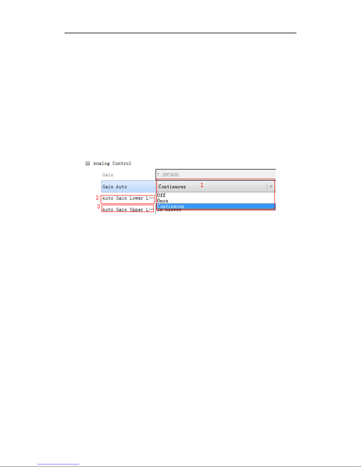
User Manual of Area Scan GigE Camera
66
Continuous mode: Adjusting Gain continuously according to the target image
brightness.
When setting single mode or continuous mode, Gain is limited by Auto Gain Lower
Limit and Auto Gain Upper Limit. Gain Range should only be set between Auto Gain
Lower Limit and Auto Gain Upper Limit.
Click Analog Control in the attribute list. Click Gain Auto. Select Gain Mode. Input
available parameter in the numeric field and finish setting, as shown in Figure 3-37.
Figure 3-37 Gain Control
The noise increases when Gain increases. Auto exposure and Auto Gain are mutually
restricted. When the image is dark, the camera will firstly increase the exposure time.
Secondly, the camera starts to adjust Gain Value when the exposure time turns to the
maximum. When the image is bright, the camera will firstly decrease Gain Value.
Secondly, it starts to adjust the exposure time when Gain Value turns to the minimum.
3.9.3 White balance
The camera supports the white balance. The white balance refers to the camera color
adjustment depending on different light sources. Adjust the Gain Value of the image’s
R channel and B channel to keep white regions white under different color
temperatures. Ideally, the proportion of R channel, G channel and B channel in the
white region is 1:1:1.
Page 67

User Manual of Area Scan GigE Camera
67
Table 3-4 White Balance Status Introduction
Status
Description
OFF
MBW mode: You can adjust the R, G, and B gain value manully. The
adjustable range is 1 to 4095, 1024 means the ratio is 1.0 .
ONCE
Adjust the white balance value according to the current scene and the
adjustment stops automatically after a while. The adjustment adopts a algrithm
that looks for the gray blocks in the Bayer data.
Note: The white balance adjustment is only available in color models.
Click Analog Control in the attribute list. Click Balance White Auto and Balance
Ratio Selector. Select available white balance status parameter and finish setting, as
shown in Figure 3-38.
Figure 3-38 White Balance Setting
3.9.4 Region Setting of Auto Functions
The camera can adjust exposure time and white balance automatically to achieve your
expectations. By default, the camera will adjust the brightness and the white balance
of the whole image. In addition, you can also set an area of interest, which is called
AOI. The camera will adjust the AOI in the image. And the area outside the selected
region will also be changed.
Page 68

User Manual of Area Scan GigE Camera
68
Regional exposure and regional white balance are generally used in the back light
scene and the scene with the great difference of regional brightness. You can also
select rectangle region. The camera will adjust the region’s exposure and white
balance to achieve the best image quality.
Click Analog Control in the attribute list. Select Auto Function AOI Selector. Choose
AOI1 or AOI2. Adjust Auto Function AOI Width value and Auto Function AOI
Height value and finish setting, as shown in Figure 3-39.
Figure 3-39 AOI Setting
Note: The available exposure region and the white balance region are the overlapped
part of the setting region and the image region. If there is no overlap, the available
region refers to the whole image.
3.9.5 Look Up Table (LUT)
LUT is the grey level mapping table. You can change the grey level in your interested
regions. The operation can be linearity curve or custom mapping curve. LUT and
Gamma are mutually exclusive.
Set the user mode to Guru Mode. Click LUT Enable and adjust the parameters, as
shown in Figure 3-40.
Page 69

User Manual of Area Scan GigE Camera
69
Figure 3-40 LUT Setting
3.9.6 Gamma Correction
The camera supports Gamma Correction. Normally, the output of the camera chip and
the number of photon that the sensor (on the chip) received are linear. And Gamma
Correction provides a non-linear output. If the Gamma value is between 0.5 and 1, the
image brightness decreases while the brightness of the dark area increases. If the
Gamma value is between 1 and 4, the image brightness increases while the brightness
of the dark area decreases.
1
0.9
0.8
0.7
0.6
0.5
0.4
0.3
0.2
0
1
0.90.80.70.6
0.50.40.3
0.2
0
0.1
0.1
Gamma=1
Gamma=0.5
Gamma=2
Gamma=4
Figure 3-41 Gamma Curve
Page 70

User Manual of Area Scan GigE Camera
70
Click Analog Control in the attribute list. Select Gamma and Gamma Selector and set
the parameter as shown in Figure 3-42.
Figure 3-42 Gamma Setting
Note: Different cameras versions have different default function parameters. The
figures shown above are only for reference.
3.9.7 Brightness, Hue and Saturation
Brightness
You can adjust the brightness of the exposure target. The default value is 64. The
larger the value, the brighter the image.
Hue
You can adjust the hue value in HSV. The default value is 128.
Saturation
You can adjust the saturation value in HSV. The default value is 128. The larger the
value, the higher the saturation and the stronger the color.
Note: The hue and the saturation are only for the color camera.
3.9.8 Image Reverse
The camera supports image horizontal mirroring. Open the mirroring function to gain
the horizontal mirroring image. Click Image Format Control. Tick Reverse X
Page 71

User Manual of Area Scan GigE Camera
71
(horizontal) or Reverse Y (vertical) according to your preference, as shown in Figure
3-43.
Figure 3-43 Tick Mirroring Function
AOI
Output
Reverse
(horizontal)
Figure 3-44 The Comparison of ROI Output Before And After Mirroring
3.9.9 HDR Cycling Mode
The camera supports HDR cycling mode: the camera can capture images in cycling
mode depending on four groups of parameters. You can configure exposure time and
Gain independently by setting parameters in each group.
Click Acquisition Control and choose Selector. Set parameters in each group. Set
Page 72

User Manual of Area Scan GigE Camera
72
available parameter in HDR Shutter and HDR Gain. Tick HDR Enable and finish
setting, as shown in Figure 3-45.
Figure 3-45 Four Groups of Parameters’ HDR Cycling.
Parameter 0
Exposure Time 0
Gain 0
Parameter 1
Parameter 2
Parameter 3
Exposure Time 1
Gain 1
Exposure 2
Gain 2
Exposure 3
Gain 3
Figure 3-46 HDR Cycling Map
Note: The camera of MV-CA030-10GM/GC does not support HDR cycling mode.
3.9.10 Test pattern
Click Image Format Control in the attribute list. Select Test Pattern and set the
parameter. The default test pattern is OFF, as shown in Figure 3-47.
Page 73

User Manual of Area Scan GigE Camera
73
Figure 3-47 Test Pattern
The camera provides four test patterns, including Mono Bar, Vertical Color Bar,
Horizontal Color Bar and Checkboard as shown in the following four figures.
Note: Color camera and black and white camera have different test patterns. The
specific test pattern is decided by the camera function.
Figure 3-48 Mono Bar Test Pattern
Figure 3-49 Vertical Color Bar Test Pattern
Page 74
User Manual of Area Scan GigE Camera
74
Figure 3-50 Horizontal Color Bar Test Pattern
Figure 3-51 Checkboard Test Pattern
3.10 I/O Electric Feature
3.10.1 Line0 Opto-isolated Input Circuit
In controlling camera I/O, Line0 input circuit can be shown in Figure 3-52.
Page 75
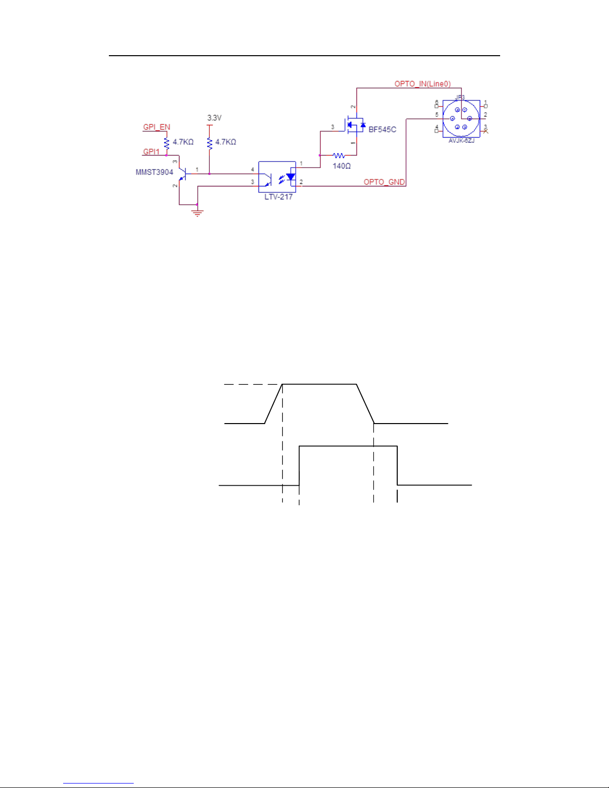
User Manual of Area Scan GigE Camera
75
Figure 3-52 Input Circuit
Logic 0 input level: 0~1VDC (OPTO_IN pin)
Logic 1 input level: 1.5~24VDC (OPTO_IN pin)
Maximum input current: 25 mA
Please make sure the input voltage is not from 1V to 1.5V as the electric status among
the two values is not stable.
Logic 1
Input Level
Logic 0
Input Level
Internal Logic
TDR TDF
Figure 3-53 Input Logic Level
Input rising delay (TDR): 2.6μs
Input falling delay (TDF): 19.2μs
3.10.2 Line1 Opto-isolated Output Circuit
In controlling I/O, Line1 output circuit can be shown in Figure 3-54.
Page 76

User Manual of Area Scan GigE Camera
76
1
2
34
5
6
1
2
34
5
6
External Resistor
External Voltage
33Ω PTC
510Ω
GPO
MMST3904
2
1
3
OPTO_OUT(Line1)
OPTO_GND
OPTO_GND
LTV-217
1
2
4
3
100Ω
Figure 3-54 Output Circuit
Maximum Line1 output current: 25 mA
Logic 1
Output Level
Logic 0
Output Level
Internal
Logic
TDR TDF TFTR
Figure 3-55 Output Logic Level
Opto-isolated output electric feature can be shown in Table 3-5 (The external voltage
is 3.3 V and the external resistance is 1 K.)
Table 3-5 Output Electric Feature
Parameter
Symbol
Value
Output Logic Low Level
VL
575mV
Output Logic High Level
VH
3.3V
Output Rising Time
TR
8.4us
Output Falling Time
TF
1.9us
Output Rising Delay
TDR
16.6us
Output Falling Delay
TDF
3.6us
Table 3-6 shows the corresponding current and the parameter of output logic low level
when the opto-isolated outputs the different external voltage and resistance.
Page 77
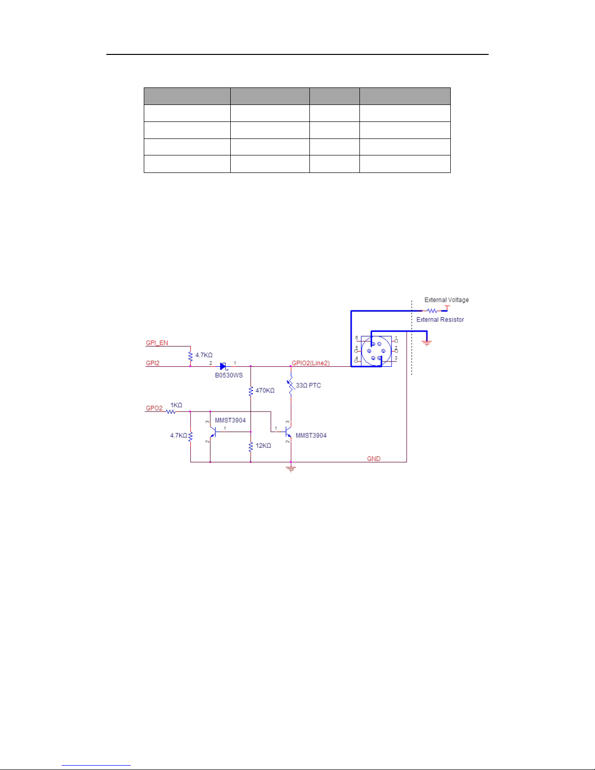
User Manual of Area Scan GigE Camera
77
Table 3-6 The Parameter of Output Logic Low Level
External Voltage
External Resistor
VL
Output Current
3.3V
1KΩ
575mV
2.7mA
5V
1KΩ
840mV
4.1mA
12V
2.4KΩ
915mV
4.6mA
24V
4.7KΩ
975mV
4.9mA
3.10.3 Line2 Configurable Bi-direction I/O Circuit
In controlling I/O, the configurable bi-direction non-isolated IO circuit of Line2 can
be shown in Figure 3-56.
Figure 3-56 Line2 Bi-direction I/O Circuit
Note: The camera of MV-CA030-10GM/GC has no such function.
1. Configure Line2 to input pin
Logic 0 input level: 0~0.5VDC (GPIO2 pin)
Logic 1 input level: 1.5~30VDC (GPIO2 pin)
Please make sure the input voltage is not from 0.5V to 1.5V as the electric status
among the two values is not stable.
Page 78
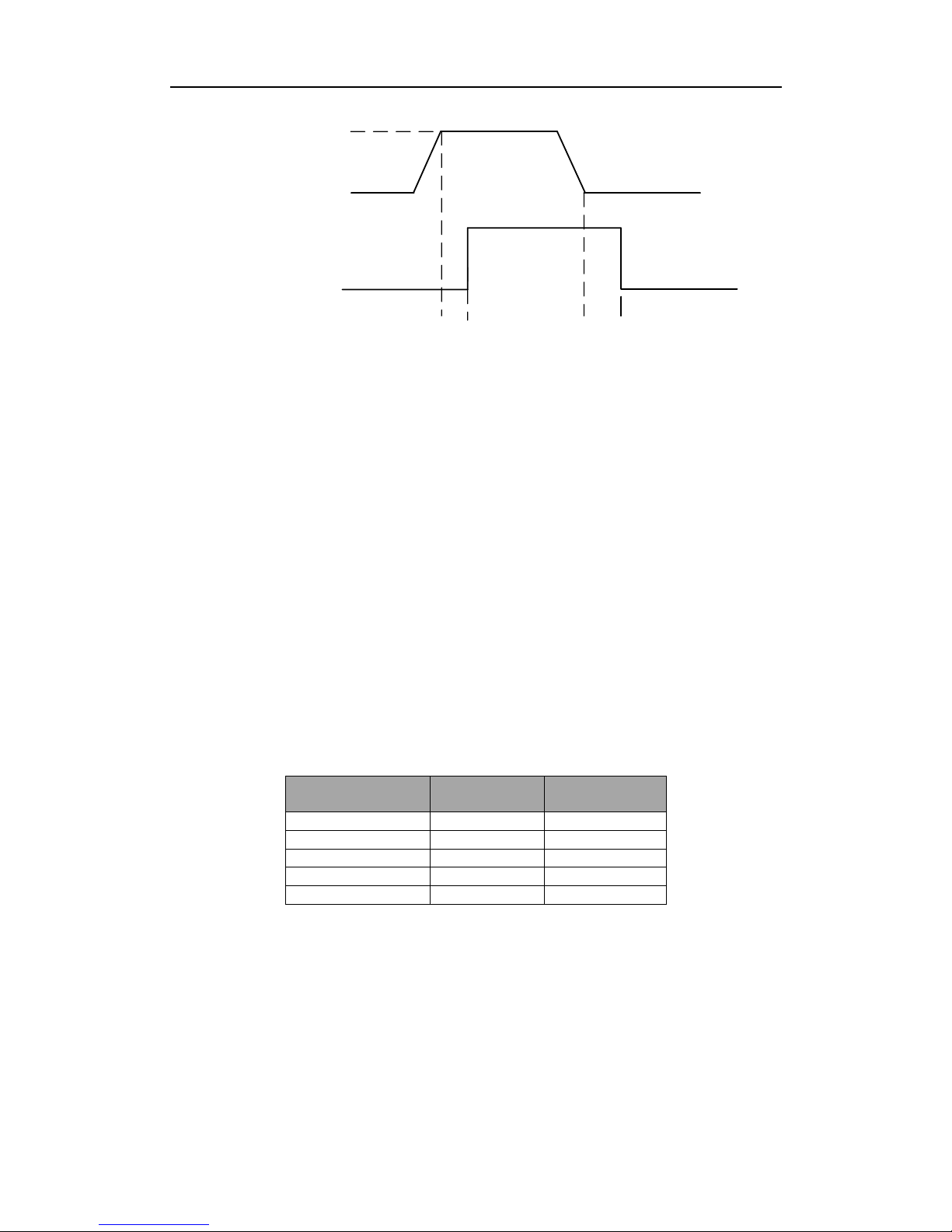
User Manual of Area Scan GigE Camera
78
Logic 1
Input Level
Logic 0
Input Level
Internal Logic
TDR TDF
Figure 3-57 Inputting Logic Level
Please connect to GND pin first to protect GPIO pin and then input voltage to Line2
pin.
2. Configure Line2 to output pin
The available maximum current is 25mA and the output impedance is 40Ω.
When the environment temperature is 25 degree centigrade, the relationship among
external voltage, impedance and the output low level can be shown in Table 3-7.
Table 3-7 The Parameter of Output Logic Low Level
External Voltage
External
Resistor
VL(GPIO2)
3.3V
1KΩ
160mV
5V
1KΩ
220mV
12V
1KΩ
460mV
24V
1KΩ
860mV
30V
1KΩ
970mV
When the external voltage of 1KΩ external resistance turns to 5V, features of output
logic level and electric feature in GPIO2 configuration can be shown in Figure 3-58
and Table 3-8.
Page 79
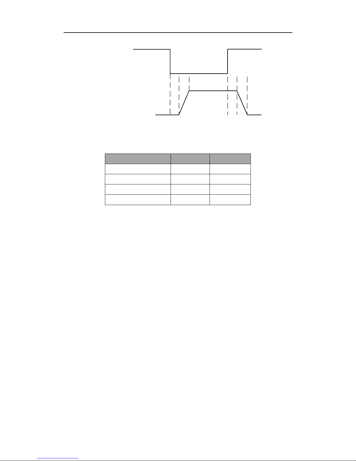
User Manual of Area Scan GigE Camera
79
Logic 1
Output Level
Logic 0
Output Level
Internal
Logic
TDR TDF TFTR
Figure 3-58 Output Logic Level
Table 3-8 Output Electric Feature
Parameter
Symbol
Value
Output Logic Low Level
TR
0.06us
Output Logic High Level
TF
0.016us
Output Rising Time
TDR
0.03us
Output Falling Time
TDF
0.28us
3.11 Transport Layer Control
3.11.1 DHCP and Persistent IP
The camera supports connecting with PC through DHCP or Persistent IP. As shown in
Figure 3-59, the camera will acquire IP according to the following order.
(1) If the camera’s Persistent IP is available and the configured Persistent IP is
available, the camera will load this Persistent IP. Or execute (2).
(2) If DHCP function is available and the acquired IP address is available, the camera
will load IP address that acquired by DHCP. Or execute (3).
(3) Acquire LLA.
Page 80

User Manual of Area Scan GigE Camera
80
Figure 3-59 The Transport Layer Control Interface
3.11.2 Efficient Bandwidth and Setting
Packet Size and Packet Delay control the 1000M Ethernet’s actual bandwidth. The
theoretical calculation of 1000M network port’s image loading bandwidth is:
BandWidth=((PacketSize–(IP+UDP+GVSP Header))/(PacketSize + MACHeader+
CRC+ Packet-Delay)) * 1000M/bps.
Normally, IP/UDP/GVSP Header takes 36 bytes. MAC Header takes 14 bytes. CRC
Page 81
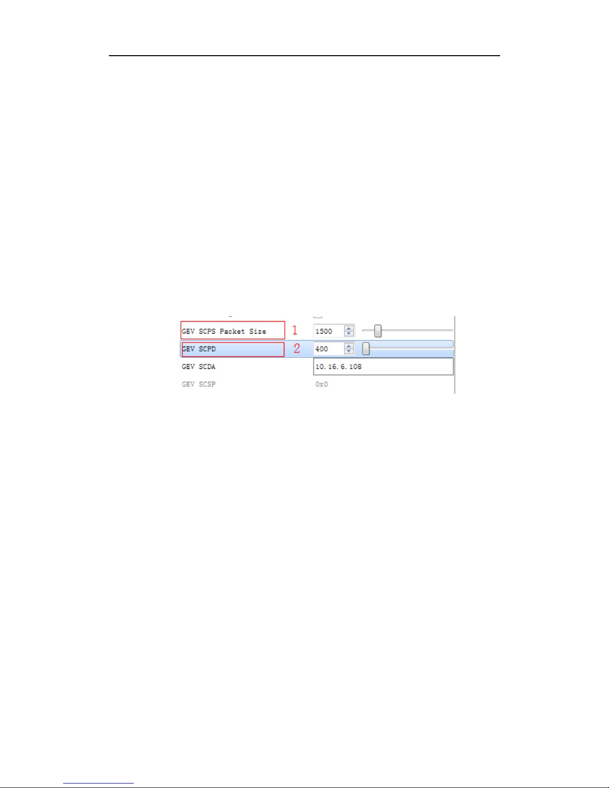
User Manual of Area Scan GigE Camera
81
takes 4 bytes. Taking setting Packet Size 1500 and Packet Delay 400 as an example,
the actual network bandwidth is
BandWidth=(1500-36)/(1500+14+4+400)*1000Mbps=759.36 Mbps
The actual network bandwidth is smaller than the theoretical one because of the
network message, GVCP, GCSP leader, Trailer and any other overheads.
Set Packet Size (GEV SCPS Packet Size) value and Packet Delay (GEV SCPD) value
by using the slider and the input box. You can set these two parameters according to
the computer performance and the network card performance in the condition of no
data package loss, as shown in Figure 3-60.
Figure 3-60 Packet Size Setting And Packet Delay Setting
3.12 User Parameter and Preference Setting
3.12.1 Parameters Saving and Loading
The camera can save four groups of parameters, including one group of factory
parameter and three groups of configurable parameters. You can save currently
configured parameter and set corresponded default parameter when logging in at next
time in User Set Control in the attribute list.
Configuration method: Select one of the parameter names in the drop-down box in
User Set Selector. Save current parameter setting. In the drop-down box of User Set
Page 82

User Manual of Area Scan GigE Camera
82
Default, select one of the parameters when the client runs, as shown in Figure 3-61.
Click Execute in both User Set Save and User Set Load.
Figure 3-61 Parameters Saving And Loading
Figure 3-62 shows the relationship among four groups of parameters.
Currently
Configured
Parameter
User Parameter 1
Unser
Parameter 2
User Parameter 3
Default
Parameter
Load
Save
Load
Figure 3-62 The Relationship Among Four Groups of Parameters
3.12.2 Embedded Information
The camera supports embedding information into the image data. The current
supporting embedded information is:
Timestamp
Analog gain
Exposure time
Page 83

User Manual of Area Scan GigE Camera
83
Average brightness
White balance gain
Frame number
Trigger counter
ROI
The above eight information will be embedded in the image data one by one
according to the client. If the information is not available, it will not be embedded.
The AOI will not affect the embedding. If the region of AOI is small, the first line of
the image data is not enough for embedding. Then the information will be embedded
in the second line.
Each embedded information of the available data will be put in the least 8 significant
bits (No matter in MONO8 or RGB24).
The Embedded information is as following:
Timestamp: Take four bytes: transmission with four available data.
Data format: The data format of the timestamp is shown in Figure 3-63.
Second_count
5bits
Cycle_count
13bits
Cycle_offset
14bits
125us
intervals
1s
intervals
Least
significant
Most
significant
Figure 3-63 Timestamp Format
Analog gain: Take four bytes: transmission with four available data. Connect the least
significant 8 bit of the four data together.
Page 84

User Manual of Area Scan GigE Camera
84
The data format of analog gain: Show the connected data directly. The range is form
0 to 1023. The Most Significant Bits will complement 0 automatically.
Exposure time: Take four bytes: transmission with four available data. Connect the
least significant 8 bit of the four data together.
The data format of the exposure time: The connected least significant 8 bit of the
four data is the number of the exposure line. Multiply the line number to 25.8μs. The
result is the exposure time. The unit is μs.
Average Brightness: Take four bytes: transmission with four available data. Connect
the least significant 8 bit of the four data together.
The data format of the average brightness: Show the connected data directly. The
range is form 0 to 4095. The Most Significant Bits will complement 0 automatically.
White balance gain: Contains three components of gain. It consumes 8 bytes in total,
including two bytes for R channel of Gain, two bytes for G channel of Gain and four
bytes for B channel of Gain. In other words, the transmission uses eight available
image data.
Data format of white balance gain: Each channel consumes 2 bytes. The range is
form 0 to 4095.
Frame number: Take four bytes.
Frame number format: Connect four bytes directly. The range is form 0 to 2^32.
Trigger counter: Take 4 bytes. The range is from 0 to 2^32.
ROI: Take three bytes in the initial position. The length and the width consume three
bytes.
The data format of ROI:
(1) The initial position of ROI takes three bytes. The length and the width consume
three bytes.
(2) The initial coordinate of ROI’ column takes one and a half bytes. The initial
coordinate of ROI’s row takes one and a half bytes. The column coordinate is in
the front of the row coordinate. The coordinate of the length and the width also
consume one and a half bytes respectively.
Page 85

User Manual of Area Scan GigE Camera
85
Click Image Format Control in the attribute list. Select Embedded Image Info Selector.
Choose the parameter in the drop-down box and finish setting, as shown in Figure
3-64.
Figure 3-64 Embedded Information
3.13 Firmware Updating
Support firmware updating via LAN. After selecting available device in the device list,
open Tool>Firmware Updating Tool in the Menu. Select available firmware updating
kit, as shown in Figure 3-65.
Figure 3-65 Firmware Update
Page 86

User Manual of Area Scan GigE Camera
86
Chapter 4
Troubleshooting
4.1 Indicator Status Definition
Table 4-1 LED Indicator Status
LED Status
Definition
Steady On
The LED indicator keeps lights on all the time
Unlit
The LED indicator keeps unlit all the time
Fast Flicker
The LED indicator flickers every 200ms to 300ms
Slow Flicker
The LED indicator flickers every 1000ms.
Extreme Slow Flicker
The LED indicator flickers every 2000ms.
4.2 Indicator Status Description
Table 4-2 LED Status Description
Indicator Status
Camera Status
Indicator in
Red
Indicator in
Blue
- - The camera is off or hardware damaged.
-
Steady On
The camera is starting up.
Fast Flicker
-
Uboot loading failed.
Extreme Slow
Flicker
-
IP address confliction or connection error
-
Slow Flicker
Idle while the camera is in the internal trigger mode.
-
Fast Flicker
Transmitting image while the camera is in the internal
trigger mode.
Extreme Slow
Flicker
Transmitting image while the camera is in the external
trigger mode.
The indicator flickers red and blue
alternately evey 1 second.
Upgrading the firmware.
Slow Flicker
-
Camera works normally but is not able to tranmit data.
Steady on
-
Upgrading the firmware failed. Contact the technical
support.
Page 87

User Manual of Area Scan GigE Camera
87
4.3 FAQ
Table 4-3 FAQ
No
Problem
Description
Possible Reasons
Solutions
1
1. The camera
cannot be detected
by the client
software.
2. The camera is
detected by the
client software but
connecting failed.
1. The camera does not
work properly.
2. The network cable is
disconected.
3. The camera and the
PC that runs the MVS
client software are not in
the same subnet.
1. Confirm if the power supply of camera
is well connected (via LED indicator), and
the network connects properly (via
network interface indicator).
2. Use MVS IP Configurator to detect the
camera and change the IP address.
3. Confirm if the GenICam and network
Filter driver are installed on the PC.
2
The camera is in
read-only status.
The camera is connected
with another client
software.
Plug out the network cable, and replace it
3 seconds later.
3
The live view of
camera is black.
1. The iris is closed.
2. Camera error
1. Open the iris.
2. Reboot the camera.
4
Camera cannot be
triggered
1. Incorrect cable
connection.
2. The camera works in
the internal trigger mode
Make sure the trigger mode is correct and
the external trigger is well connected.
5
The live view and
image is normal,
while the image
saved could not be
displayed properly.
The image format
mismacthes.
Make sure the image format what you
saved is supported.
Page 88

User Manual of Area Scan GigE Camera
88
Chapter 5 Support
You can also get support through the following ways:
1. Website -- Visit www.hikrobotics.com/en/ for documentation and online technical
support.
2. Hotline -- contact us at 400-700-5998.
3. Mail -- 400@hikvison.com, our support staff will reply in time.
Page 89

User Manual of Area Scan GigE Camera
89
Appendix
Revision History
Doc.
ID No.
Version
Revision
Date
Revision Description
UD.6L
0201D
2172A
01
V1.0.0
2016/02/19
Initial version.
UD.6L
0201D
2172A
01
V1.1.0
2017/10/11
1. The sensor type for all cameras was specified
in model details
2. The sensor size for all cameras was
individually described in the specifications
3. The data format for all cameras was updated
4. The frame rate for all cameras was updated
regardless of the resolution
5. The weight of the camera was changed from
‘67g’ to ‘68g’ in Section1.3.1 on page 10
6. The specification for MV-CA013-20GC was
added in Section 1.3.3 on page 11
7. The dynamic range was changed from
‘>80dB’ to ‘>60dB’ in Section 1.3.3 on page
11
8. The gain was changed from ‘0-24dB’ to
‘0-15dB’ in Section 1.3.3 on page 12
9. The exposure time was changed from
‘5μs-5sec’ to ‘10μs-10sec’ in Section 1.3.3 on
page 12
10. The quantum efficiency curve for
MV-CA013-20GC was added in Section 1.3.4
on page 13
11. The exposure time for MV-CA030-10GM/GC
was changed from ‘20μs-10sec’ to
‘26μs-10sec’ in Section 1.3.7 on page15
12. The dimension of the camera was changed
from ‘44mm×29mm×58mm’ to
‘44mm×29mm×60mm’ in Section 1.3.7 on
page 15
13. The specification of MV-CA050-20GC was
added
Page 90

User Manual of Area Scan GigE Camera
90
14. The resolution for MV-CA050-20GM was
corrected in Section 1.3.9 on page 16
15. The exposure time was changed from ‘5μs-5s’
to ‘10μs-10sec’ in Section 1.3.9 on page 17
16. The quantum efficiency curve for
MV-CA050-20GC was added in Section
1.3.10 on page 17
17. The specification of MV-CA060-10GM was
removed in Section 1.3.11 on page 18
18. The gain of MV-CA060-10GC was changed
from ‘0-30dB’ to ‘0-20dB’ in Section 1.3.11
on page 18
19. The exposure time was changed from
‘27μs-10s’ to ‘27μs-2.5sec’ in Section 1.3.11
on page 18
20. The specifications and response curves of the
following cameras were added:
MV-CA060-11GM, MV-CA003-50GM/GC,
MV-CA023-10GM/GC,
MV-CA050-10GM/GC,
MV-CE100-30GM/GC,
MV-CA003-20GM/GC, MV-CA013-20GN,
MV-CA050-20GN
21. Support details were added in Chapter 5
22. The typesetting of the manual was slightly
changed
23. Added Revision History
24. Modified document name according to
standardizing naming rule
Page 91

User Manual of Area Scan GigE Camera
91
 Loading...