

Page 1

iDS-TP40-16B Traffic Incident Detection Server
User Manual
UD07079B
Page 2

User Manual of iDS-TP40-16B Traffic Incident Detection Server
User Manual
COPYRIGHT © 2017 Hangzhou Hikvision Digital Technology Co., Ltd.
ALL RIGHTS RESERVED.
Any and all information, including, among others, wordings, pictures, graphs are the properties of
Hangzhou Hikvision Digital Technology Co., Ltd. or its subsidiaries (hereinafter referred to be
“Hikvision”). This user manual (hereinafter referred to be “the Manual”) cannot be reproduced,
changed, translated, or distributed, partially or wholly, by any means, without the prior written
permission of Hikvision. Unless otherwise stipulated, Hikvision does not make any warranties,
guarantees or representations, express or implied, regarding to the Manual.
About this Manual
This Manual is applicable to Traffic Incident Detection Server.
The Manual includes instructions for using and managing the product. Pictures, charts, images and
all other information hereinafter are for description and explanation only. The information
contained in the Manual is subject to change, without notice, due to firmware updates or other
reasons. Please find the latest version in the company website
(http://overseas.hikvision.com/en/).
Please use this user manual under the guidance of professionals.
Trademarks Acknowledgement
and other Hikvision’s trademarks and logos are the properties of Hikvision in various
jurisdictions. Other trademarks and logos mentioned below are the properties of their respective
owners.
Legal Disclaimer
TO THE MAXIMUM EXTENT PERMITTED BY APPLICABLE LAW, THE PRODUCT DESCRIBED, WITH ITS
HARDWARE, SOFTWARE AND FIRMWARE, IS PROVIDED “AS IS”, WITH ALL FAULTS AND ERRORS,
AND HIKVISION MAKES NO WARRANTIES, EXPRESS OR IMPLIED, INCLUDING WITHOUT LIMITATION,
MERCHANTABILITY, SATISFACTORY QUALITY, FITNESS FOR A PARTICULAR PURPOSE, AND
NON-INFRINGEMENT OF THIRD PARTY. IN NO EVENT WILL HIKVISION, ITS DIRECTORS, OFFICERS,
EMPLOYEES, OR AGENTS BE LIABLE TO YOU FOR ANY SPECIAL, CONSEQUENTIAL, INCIDENTAL, OR
INDIRECT DAMAGES, INCLUDING, AMONG OTHERS, DAMAGES FOR LOSS OF BUSINESS PROFITS,
BUSINESS INTERRUPTION, OR LOSS OF DATA OR DOCUMENTATION, IN CONNECTION WITH THE
USE OF THIS PRODUCT, EVEN IF HIKVISION HAS BEEN ADVISED OF THE POSSIBILITY OF SUCH
DAMAGES.
REGARDING TO THE PRODUCT WITH INTERNET ACCESS, THE USE OF PRODUCT SHALL BE WHOLLY
AT YOUR OWN RISKS. HIKVISION SHALL NOT TAKE ANY RESPONSIBILITIES FOR ABNORMAL
OPERATION, PRIVACY LEAKAGE OR OTHER DAMAGES RESULTING FROM CYBER ATTACK, HACKER
ATTACK, VIRUS INSPECTION, OR OTHER INTERNET SECURITY RISKS; HOWEVER, HIKVISION WILL
PROVIDE TIMELY TECHNICAL SUPPORT IF REQUIRED.
SURVEILLANCE LAWS VARY BY JURISDICTION. PLEASE CHECK ALL RELEVANT LAWS IN YOUR
JURISDICTION BEFORE USING THIS PRODUCT IN ORDER TO ENSURE THAT YOUR USE CONFORMS
THE APPLICABLE LAW. HIKVISION SHALL NOT BE LIABLE IN THE EVENT THAT THIS PRODUCT IS
USED WITH ILLEGITIMATE PURPOSES.
IN THE EVENT OF ANY CONFLICTS BETWEEN THIS MANUAL AND THE APPLICABLE LAW, THE LATER
PREVAILS.
1
Page 3
User Manual of iDS-TP40-16B Traffic Incident Detection Server
Symbol
Description
Provides additional information to emphasize or supplement
important points of the main text.
Indicates a potentially hazardous situation, which if not avoided,
could result in equipment damage, data loss, performance
degradation, or unexpected results.
Indicates a hazard with a high level of risk, which if not avoided, will
result in death or serious injury.
Symbol Conventions
The symbols that may be found in this document are defined as follows.
Safety Instructions
Please adopt the power adapter which can meet the safety extra low voltage (SELV) standard.
To reduce the risk of fire or electrical shock, do not expose this product to rain or moisture.
This installation should be made by a qualified service person and should conform to all the
local codes.
Please install blackouts equipment into the power supply circuit for convenient supply
interruption.
If the product does not work properly, please contact your dealer or the nearest service center.
Never attempt to disassemble the camera yourself. (We shall not assume any responsibility for
problems caused by unauthorized repair or maintenance.)
Preventive and Cautionary Tips
Make sure the power supply voltage is correct before using the device.
Do not drop the device or subject it to physical shock.
Do not place the device in extremely hot, cold temperatures (please refer to the product
specification for the operating temperature), dusty or damp environment, and do not expose
it to high electromagnetic radiation.
To avoid heat accumulation, good ventilation is required for a proper operating environment.
Keep the device away from water and any liquid.
While shipping, the device should be packed in its original packing.
2
Page 4

User Manual of iDS-TP40-16B Traffic Incident Detection Server
Improper use or replacement of the battery may result in hazard of explosion. Please use the
manufacturer recommended battery type.
3
Page 5

User Manual of iDS-TP40-16B Traffic Incident Detection Server
Table of Contents
Chapter 1 Function Overview ......................................................................................................... 6
1.1 Main Functions ................................................................................................................... 6
1.2 Features .............................................................................................................................. 6
Chapter 2 Hardware Introduction .................................................................................................. 8
2.1 Specifications ..................................................................................................................... 8
2.2 Front Panel of iDS-TP40-16B .............................................................................................. 8
2.3 Rear Panel of iDS-TP40-16B ............................................................................................... 9
2.4 Available Models .............................................................................................................. 10
2.5 Installation and Typical Application ................................................................................. 10
2.5.1 Installation ............................................................................................................... 10
2.5.2 Typical Application .................................................................................................. 16
Chapter 3 Getting Started .............................................................................................................. 17
3.1 Activation ......................................................................................................................... 17
3.1.1 Activating via SADP ................................................................................................. 17
3.1.2 Activating via Web Browser .................................................................................... 19
3.2 Login ................................................................................................................................. 20
Chapter 4 Network Configuration ............................................................................................... 21
4.1 Viewing Network Parameters of Smart Analysis Units .................................................... 21
4.2 Configuring Network of Traffic Incident Detection Server ............................................... 22
Chapter 5 System Configuration .................................................................................................. 25
5.1 Basic Configuration .......................................................................................................... 25
5.2 Time Configuration .......................................................................................................... 25
Chapter 6 Resource Management ................................................................................................. 27
6.2 Adding Group ................................................................................................................... 27
6.3 Adding Device ................................................................................................................... 29
6.4 Adding Camera ................................................................................................................. 30
6.5 Modifying the Added Device/Camera .............................................................................. 33
6.6 Modifying the Added Group ............................................................................................ 33
6.7 Deleting the Added Device/Camera ................................................................................. 34
6.8 Deleting the Added Group ............................................................................................... 34
6.9 Exporting Control Center/Area/Device Information ........................................................ 35
6.10 Importing Control Center/Area/Device Information ..................................................... 36
4
Page 6

User Manual of iDS-TP40-16B Traffic Incident Detection Server
Chapter 7 Live View ....................................................................................................................... 38
Chapter 8 Camera Configuration ................................................................................................. 40
8.1 Configuring Camera Location ........................................................................................... 40
8.2 Configuring Picture Composition ..................................................................................... 40
8.3 Configuring Character Overlay ......................................................................................... 41
8.4 Configuring Scene ............................................................................................................ 43
8.4.1 Configuring Lane ..................................................................................................... 43
8.4.2 Configuring Incident Rule ........................................................................................ 45
8.4.3 Configuring Preset Scene ........................................................................................ 50
8.5 Configuring Manual Evidence Capture ............................................................................ 52
8.6 Configure Scene Patrol ..................................................................................................... 53
Chapter 9 Management and Maintenance .................................................................................. 55
9.1 Viewing Performance of the Server ................................................................................. 55
9.2 Searching Log Files ........................................................................................................... 56
9.3 Upgrading Software .......................................................................................................... 57
9.4 Restoring Default Settings ................................................................................................ 59
9.5 Managing User Accounts .................................................................................................. 60
5
Page 7

User Manual of iDS-TP40-16B Traffic Incident Detection Server
Chapter 1 Function Overview
Traffic Incident Detection Server iDS-TP40-16B is a high performance intelligent multi-channel
video analysis device. It is designed for real-time detection of multiple traffic incidents in
urban/expressway/tunnel, and it also collects traffic data and performs picture capture and license
plate recognition. Different models of this series support intelligent incident detection of 4/8/16-ch
network cameras and traffic data collection.
1.1 Main Functions
Supports access of average surveillance cameras, smart cameras, monitoring point camera and
e-police cameras, etc.
Multiple incident detection: Illegal parking, wrong-way driving, pedestrian, driving on the lane
line, illegal lane change, objects dropped down, occupy emergency lane, congestion, flow,
roadblock, construction.
Multiple traffic data collection: vehicle type, lane traffic, lane speed, headway time, headway
distance, lane occupation time ratio, lane occupation space ratio, queue length and traffic
status.
Supports access of 4/8/16-ch cameras, automatic traffic incident detection, incident picture
capture, and traffic data collection.
Supports main stream resolutions of 3 MP and below, including 3 MP (2048 × 1536), 2MP
(1920 × 1200, 1920 × 1080, 1600 × 1200), 1 MP (1360 × 1024, 1280 × 720).
1.2 Features
Reliability
1. Operating temperature: 5 °C to 40 °C .
2. Operating humidity: 10% to 90% (non-condensing).
3. Continuous video incident detection result output.
Utility
1. Easy operation, friendly UI.
2. Logs for configuration and alarms; running environment information available in maintenance.
Security
User permission management.
6
Page 8

User Manual of iDS-TP40-16B Traffic Incident Detection Server
Conformity
1. International electronic product certification, including CCC, CE and FCC, etc.
2. Production permit.
7
Page 9
User Manual of iDS-TP40-16B Traffic Incident Detection Server
Item
iDS-TP40-16B
Operation Interface
Web
Network Interface
4 × 10/100/1000M self-adaptive network interface
VGA Interface
4 × USB 3.0; 2 × USB 2.0
Indicator
UID, alarm, power and status
Button
Power and reset
Power
1+1 redundant hot-plugging power module
Dimensions (W × D × H)
439 × 591 × 44 mm (16.9 × 23.3 × 1.7 inch); standard 19
inch 1U chassis
Operating Temperature
5 °C to 40 °C
Operating Humidity
10% to 90% (non-condensing)
Chapter 2 Hardware Introduction
2.1 Specifications
Below is a hardware list of traffic incident detection server, here iDS-TP40-16B is taken as an
example.
Table 2-1 Technical Specifications
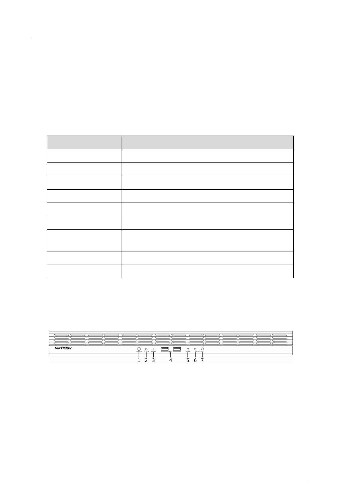
2.2 Front Panel of iDS-TP40-16B
Please see below for illustration and detailed information of buttons and indicators on the front
panel of the device.
Figure 2-1 Front Panel
8
Page 10
User Manual of iDS-TP40-16B Traffic Incident Detection Server
No.
Item
Description
1
Power Button/Indicator
Power button: turn on/off the power; press and hold
for 3s to force shut down the device.
Power indicator: turns blue when the device is
powered on.
2
Status Indicator
Solid blue: device is operating normmaly.
Off: error occurred.
3
Reset Button
Press to restart the device.
4
USB Interface
2 × USB 2.0
5
Alarm Indicator
Solid red: main board error.
6
UID Indicator
Turns blue when UID is enabled to quickly locate the
server.
7
UID Button
Turns on/off UID indicator.
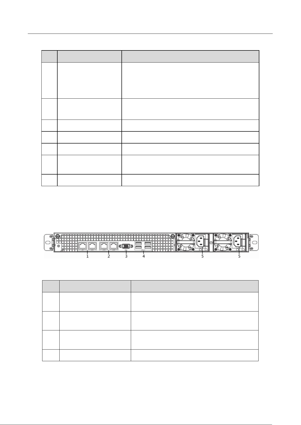
No.
Item
Description
1
LAN1/LAN2 Network
Interface
2 × 1000M data interface
2
LANA/LANB Network
Interface
2 × management interface
3
VGA Interface/Debugging
Interface
For device debugging.
4
USB 3.0 Interface
4 × USB 3.0.
Table 2-2 Buttons and Indicators on Front Panel
2.3 Rear Panel of iDS-TP40-16B
Please see below for illustration and detailed information of interfaces and indicators on the rear
panel of the device.
Figure 2-2 Rear Panel
Table 2-3 Interfaces and Indicators on Rear Panel
9
Page 11
User Manual of iDS-TP40-16B Traffic Incident Detection Server
5
Redundant 1+1 Power
Input Interface
Connects to power cable and provides redundant
power.
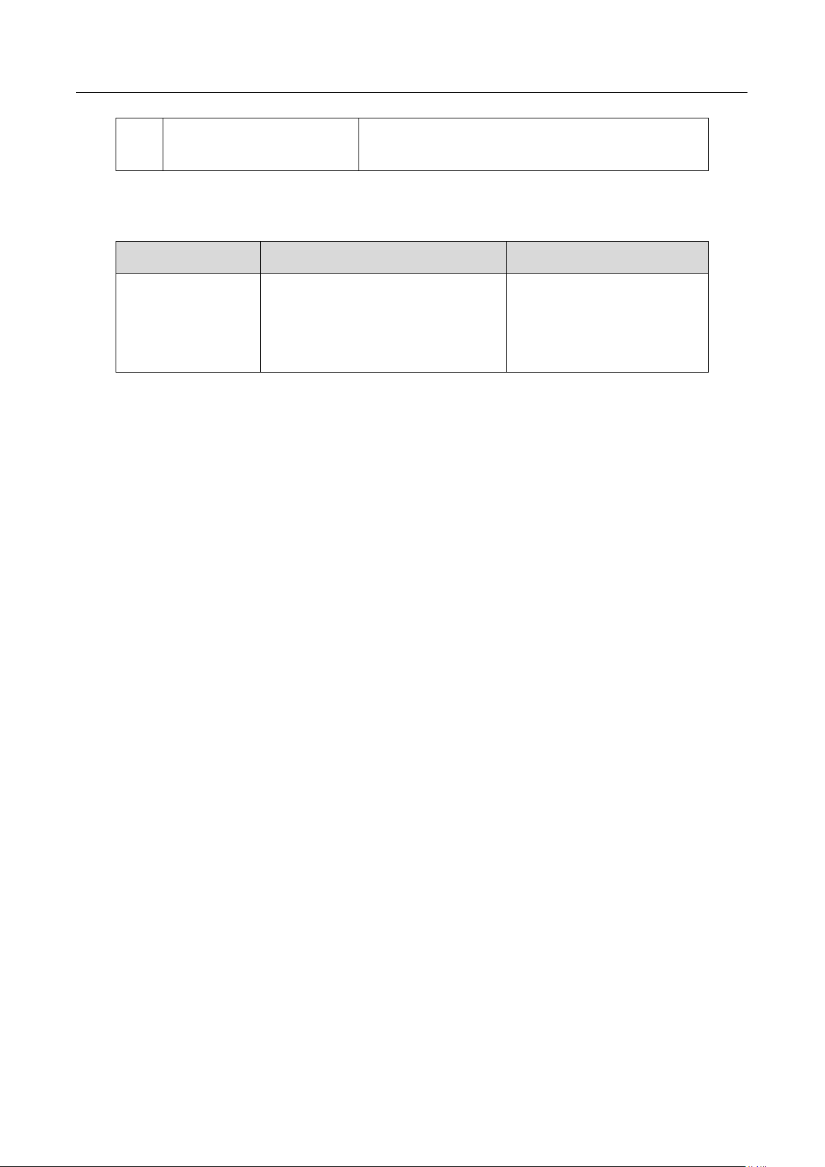
Product Series
Features
Remark
iDS-TP40-16B
Access of 16-ch camera for
real-time video stream analysis;
Self-adaptive to different
resolutions.
The hardware that is
responsible for real-time
video analysis varies with
the number of channels.
2.4 Available Models
2.5 Installation and Typical Application
2.5.1 Installation
Cautions
Operating temperature
If the device will be installed on an independent or multiple racks, the operating temperature of
the rack may exceed the room temperature. Please consider the maximum recommended ambient
temperature (TMRA) of the installation environment and the device.
Heat dissipation
The device should be installed in one chassis to avoid the reduction in amount of heat dissipation
airflow required by security operations.
Device load
The device should be installed in one chassis to avoid unbalanced load.
Circuit overload
Circuit overload protection should be taken into consideration for scenario when the circuit of
device accepts other power connection that may affect the circuit load.
Grounding
The rack should be grounded at any time. Pay attention to the branch circuit that is directly
connected besides the main power connection.
Installation position
Keep enough space in the rack and reserve space before and behind the rack to ensure proper
airflow and maintenance.
10
Page 12

User Manual of iDS-TP40-16B Traffic Incident Detection Server
Preparation
Check the whether the packaging is damaged.
Pick a proper installation location that is dust-free and well-ventilated.
Avoid heat/noise generating environment; be close to grounded power socket.
Keep the device in dry environment. Rain drops, moisture and liquids will corrode the circuit.
The device is a precision equipment and should be handled with anti-static measures during
installation and operation.
The server should not share a power socket with other devices; extension cord is not
recommended; connect the server to a UPS if possible.
The device is a Class A product and may cause radioactive interference. In this case, necessary
measures should be taken.
Installing Power Module
The device comes with two standard 100 to 240 V power modules. To install a power modules:
1. Align the module with the rail.
2. Clip the rear of module into the slot and push the module along the rail.
3. Push the module further until its front is leveled with the rear panel of the server to make sure
the module is successfully mounted.
Removing Power Module
To remove a power module:
1. Press the blue paddle to the left while pulling the module out.
2. Pull the module out until it is completely removed from the server.
Installing on Chassis
The chassis should match the size of guide rails. The distance between the front and back columns
of the chassis should be within the range of 660 mm to 850 mm.
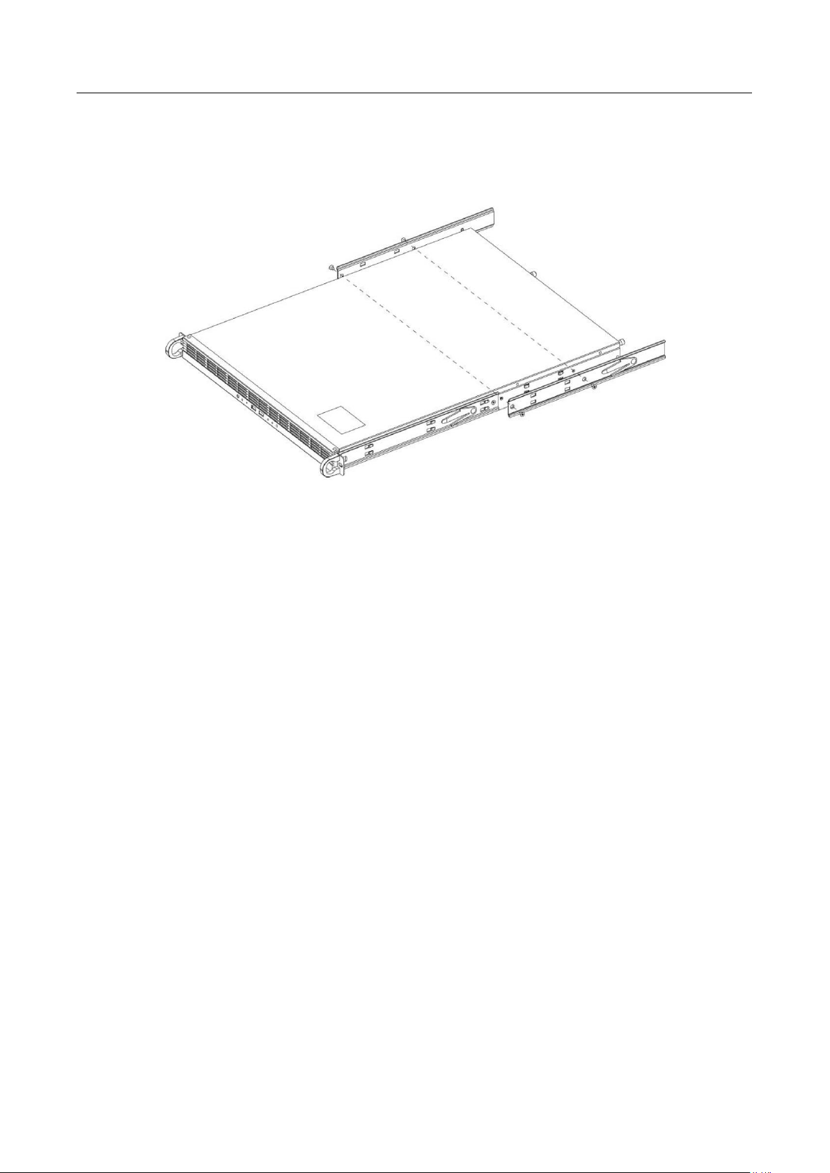
Installing Inner Rail
1. Ensure that the second half of left and right inner rails is set into place. The first half of the
inner rails has already been preinstalled on the device.
2. Clip the second part of the inner rail into the hook of both sides of the device and make sure
the screw holes are aligned to those on the inner rails.
11
Page 13
User Manual of iDS-TP40-16B Traffic Incident Detection Server
3. Fix the second part of inner rail on the device using 2 M4 flat head screws as shown in Figure
2-3.
4. Repeat the previous step to install the inner rail on the other side.
Figure 2-3 Install Inner Rails
Installing Outer Rail
1. Select 1U of space on the chassis for installation. Fix M5 cage nuts inside the chassis: 6 in the
front, 4 in the back.
2. Assemble the first and second parts of the outer rails.
3. Pull out the second part of the rail (marked with "back"), stretch it to fit installation on chassis.
4. Fix the first and second part of the outer rails on the front and back column of the chassis
respectively using 2 groups of M5x10 screws and bowl washers, as shown in Figure 2-4.
5. Repeat the previous step to install rails on the other side. Make sure the rails are paralleled.
12
Page 14

User Manual of iDS-TP40-16B Traffic Incident Detection Server
Figure 2-4 Install Outer Rails
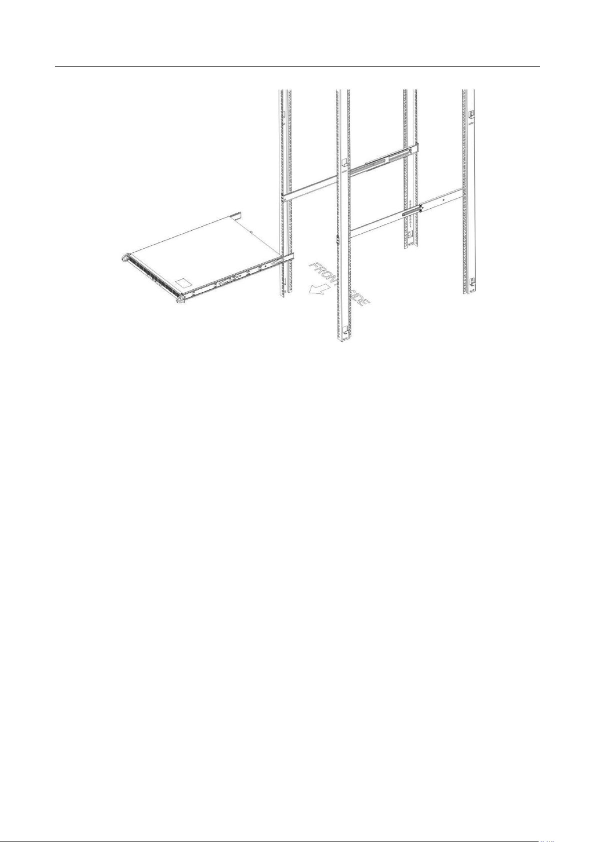
Installing Server on Chassis
1. Make sure the inner rails are installed on the server and the outer rails are installed on the
chassis.
2. Align the inner and outer rails, as shown in Figure 2-5.
13
Page 15
User Manual of iDS-TP40-16B Traffic Incident Detection Server
Figure 2-5 Install Server on Chassis
3. Push the server along the outer rails and 2 clicks can be heard. Push the server until it is
completely mounted into the chassis.
4. (Optional) Fix the server on the chassis using 2 groups of M5x16 screws and bowl washers, as
shown in Figure 2-6. The installation is completed.
14
Page 16

User Manual of iDS-TP40-16B Traffic Incident Detection Server
Figure 2-6 Fix the Server
When pulling the server out of the chassis, move the plastic paddle up on the left, and move the
plastic paddle down on the right.
15
Page 17
User Manual of iDS-TP40-16B Traffic Incident Detection Server
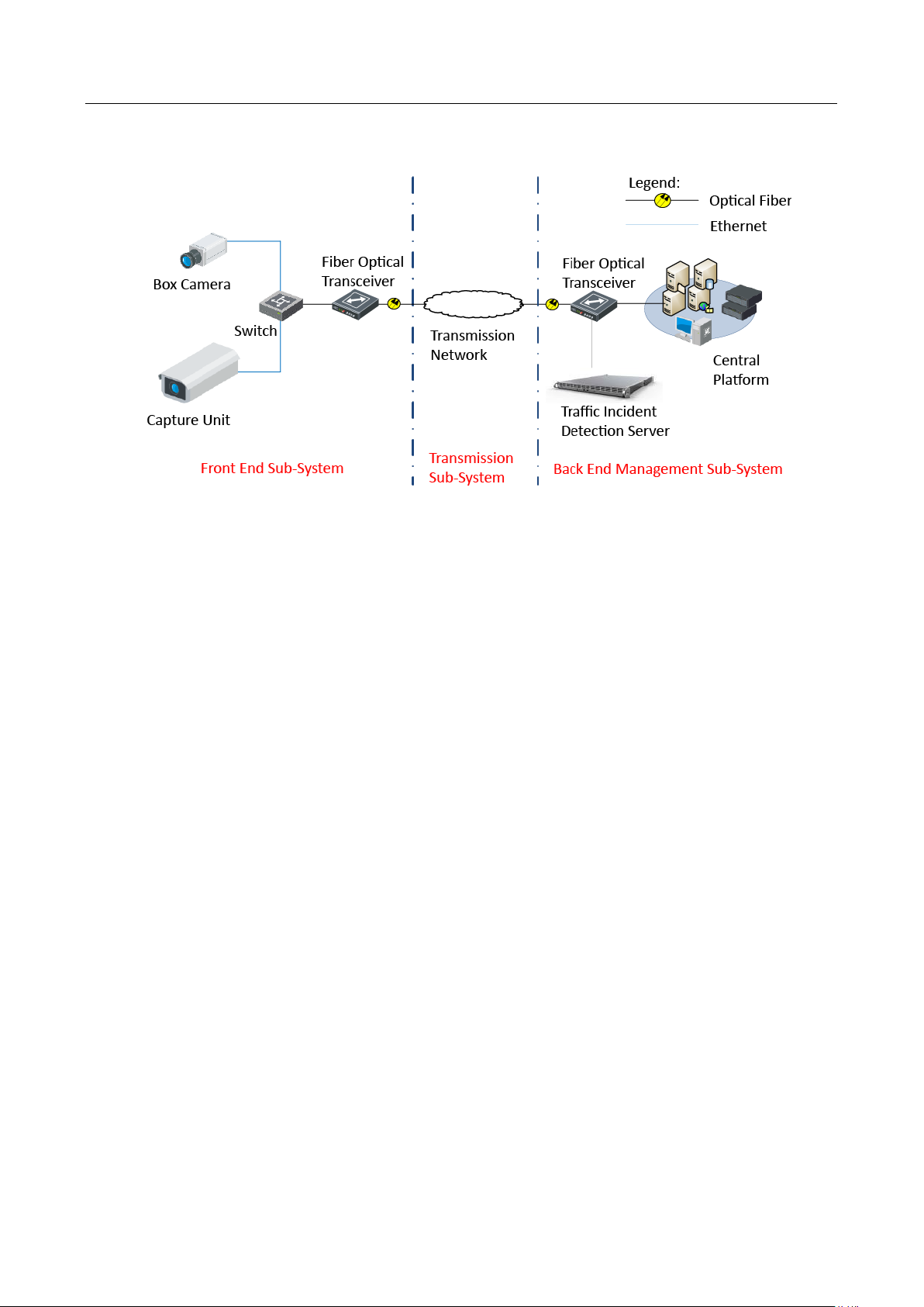
2.5.2 Typical Application
Figure 2-7 Typical Application
16
Page 18
User Manual of iDS-TP40-16B Traffic Incident Detection Server
Chapter 3 Getting Started
3.1 Activation
You need to active the device and set the password for first-time login. You can activate via SADP or
web browser.
3.1.1 Activating via SADP
SADP software is enclosed on the compact disc. You can also download it from the company
website.
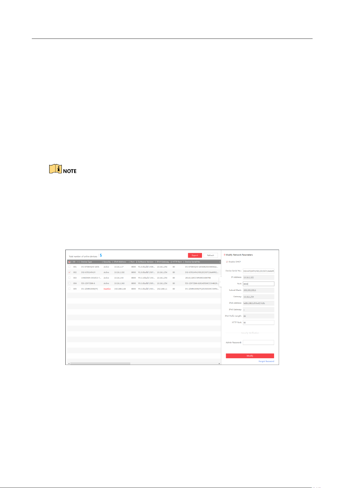
Step 1 Install SADP software. After launching the SADP software, it automatically searches the
online devices every 1 minute from the subnet where your computer locates. It displays the
total number and information of the searched devices in the device list. Device information
including the device type, IP address, port number, gateway, etc. will be displayed as the
figure below.
Figure 3-1 SADP Activation
Step 2 Select the device which you need to activate by checking the checkbox and the device
information will be displayed in a list on the right side. In Activate the Device panel, create a
password for the device and confirm the password. The system will judge password strength
automatically, and we highly recommend you to use a strong password to ensure your data
security.
17
Page 19
User Manual of iDS-TP40-16B Traffic Incident Detection Server
Figure 3-2 Create the Password
STRONG PASSWORD RECOMMENDED–A strong password ranges from 8 to 16 characters, and
must contain at least two of the following categories: numbers, lowercases, uppercases and special
characters. And we recommend you reset your password regularly, especially in the high security
system, resetting the password monthly or weekly can better protect your product.
Step 3 Click Activate to activate the device. A “The device is activated.” hint window pops up when
the password is set successfully.
Step 4 Modify the network parameters. Select the device to be modified in the device list by
checking the checkbox and the network parameters of the device will be displayed in Modify
Network Parameters panel on the right side. Set the network parameters including IP
address, sub network mask, gateway, etc.
18
Page 20

User Manual of iDS-TP40-16B Traffic Incident Detection Server
Figure 3-3 Modify the Parameters
Step 5 Enter the password of the admin account of the device in the Admin Password field and
click Modify to modify the parameters.
When setting IP address, keep the device IP address and the computer IP address in the
same network segment.
“Admin” is device’s administrator user. We recommend you to create a new user to operate
for protecting your data security.
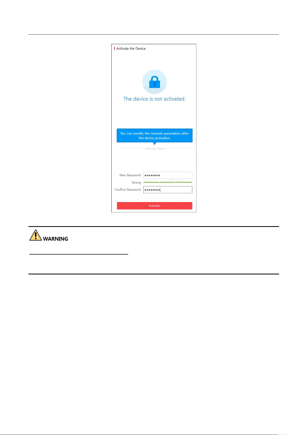
3.1.2 Activating via Web Browser
Step 1 Enter the default IP address (192.168.1.64) of the device in the address bar of the web
browser and press the Enter key to enter the activation page.
Figure 3-4 Activation
19
Page 21

User Manual of iDS-TP40-16B Traffic Incident Detection Server
Step 2 Enter the user name (admin), activation password, and confirm the password.
Step 3 Click Activate to activate the device.
STRONG PASSWORD RECOMMENDED–A strong password ranges from 8 to 16 characters, and
must contain at least two of the following categories: numbers, lowercases, uppercases and special
characters. And we recommend you reset your password regularly, especially in the high security
system, resetting the password monthly or weekly can better protect your product.
3.2 Login
Purpose
You can log in to the device via web browser for further operations such as live view, local
configuration, etc.
Step 1 In the address bar of the web browser, enter the IP address of the device, and press the
Enter key to enter the login page.
Step 2 Enter the user name and password.
Figure 3-5 Login
Step 3 Click Login to log in to the device.
Step 4 For the first time login, you should install the plug-in before you can access the functions.
Click Please click here to download and install the plug-in. Close the browser when
installing the plug-in. on the live view page, run and install the plug-in according to the
prompt. After the installation of plug-in, re-open the web browser and log in again.
Please close your web browser during the installation of the plug-in.
20
Page 22

User Manual of iDS-TP40-16B Traffic Incident Detection Server
Chapter 4 Network Configuration
Purpose
The traffic incident detection server contains eight smart analysis units, used to do smart analysis
of cameras. You can view the information of the smart analysis units, and configure the network of
the server.
4.1 Viewing Network Parameters of Smart Analysis Units
Step 1 Go to Network Management.
Figure 4-1 Smart Analysis Units Information
Step 2 View the information of the smart analysis units, including the IP Address, Serial No., Version,
Fan Status, Online Status, Status, and UID Indicator.
Step 3 (Optional) Click Reboot to reboot the units or click Shutdown to shut down the units.
Step 4 Click Local to enter the configuration page. The page shows the network parameters of the
smart analysis units.
Figure 4-2 Basic Configuration
Step 5 View the parameters below.
Name: the name of the smart analysis units.
Smart Analysis Unit IP Address: the IP address of the smart analysis units.
Resource Allocation: it shows the amount of the smart analysis units in the server.
21
Page 23

User Manual of iDS-TP40-16B Traffic Incident Detection Server
You cannot configure the network parameters of the smart analysis units.
4.2 Configuring Network of Traffic Incident Detection Server
Purpose
There are four network interfaces of the server. LAN represents G1 and G2 interfaces. They share
one IP address for debugging. LAN1 represents G3 interface. LAN2 represents G4 interface. G3 and
G4 are in different network segments for device management, and can be configured in the same
network segment. You can configure the network parameters of the network interfaces.
Step 1 Go to Network Management > Local > Configuration > Network Configuration.
Step 2 Configure LAN.
1) Click LAN to enter the LAN Configuration page.
Figure 4-3 Network Configuration
Figure 4-4 LAN Configuration
22
Page 24

User Manual of iDS-TP40-16B Traffic Incident Detection Server
2) Configure the network parameters.
3) Click Save and the note pops up as below.
4) Click OK to save the settings.
Step 3 Configure LAN1 or LAN2.
Figure 4-5 Note (1)
1) Click LAN1 or LAN2 to enter the configuration page.
Figure 4-6 LAN1 Configuration
2) Configure the network parameters.
3) Click Save and the note pops up as below.
23
Page 25

User Manual of iDS-TP40-16B Traffic Incident Detection Server
4) Click OK to save the settings.
Figure 4-7 Note (2)
24
Page 26

User Manual of iDS-TP40-16B Traffic Incident Detection Server
Chapter 5 System Configuration
5.1 Basic Configuration
Purpose
You can configure the IP address and port of the listening server, and the SDK port of the device.
Step 1 Go to System Management > System Configuration > Basic Configuration.
Figure 5-1 Basic Configuration
Step 2 Enter the Listening Server IP Address, Listening Server Port, and SDK Port.
Step 3 Click Save to save the settings.
5.2 Time Configuration
Purpose
You can synchronize time by NTP or manually.
Step 1 Go to System Management > System Configuration > Time Configuration.
Step 2 Synchronize time.
NTP
1) Click NTP radio button to enable the function.
2) Configure the following parameters.
Server Address: IP address of NTP server.
NTP Port: Port of NTP server.
Interval: The time interval between the two synchronizing actions with NTP server.
25
Page 27

User Manual of iDS-TP40-16B Traffic Incident Detection Server
Figure 5-2 Time Sync. by NTP Server
If the device is connected to a public network, you should use a NTP server that has a time
synchronization function, such as the server at the National Time Center (IP Address:
210.72.145.44). If the device is set in a customized network, NTP software can be used to establish
a NTP server for time synchronization.
Manual Time Sync.
1) Click Manual Time Sync. radio button to enable the function.
2) Click Set Time text field to set time in the pop-up calendar.
Step 3 Click Save to save the settings.
Figure 5-3 Manual Time Sync.
26
Page 28

User Manual of iDS-TP40-16B Traffic Incident Detection Server
Chapter 6 Resource Management
Purpose
You need to add cameras to the server and manage them in resource management. The cameras
should be added according to the group structure. There are four levels of the structure. The first
level is administrator and you can add control centers or areas to it. In each control center, you can
add control centers or areas to it. Devices can only be added to the control centers, and cameras
can only be added to areas. Devices can be understood as cameras.
Figure 6-1 Group Structure
6.2 Adding Group
Purpose
You should add group first before adding cameras or devices to it. The group can be a control
center or an area.
Step 1 Go to Resource Management.
Figure 6-2 Resource Management
Step 2 Click Add.
Step 3 Select Add Group.
Step 4 Select the Type. Control Center and Area are selectable.
Step 5 Click Group and the page pops up as below.
27
Page 29

User Manual of iDS-TP40-16B Traffic Incident Detection Server
Figure 6-3 Select Group
Step 6 Select the group to add the control center or area.
You cannot add a control center to an area or add an area to an area. Or the note pops up to
remind you to check if the selected one is local control center.
Figure 6-4 Note (3)
Step 7 Enter the Name of the group.
28
Page 30

User Manual of iDS-TP40-16B Traffic Incident Detection Server
Figure 6-5 Add Group
Step 8 Click Save to save the settings.
6.3 Adding Device
Purpose
You can add device to administrator or a control center.
Step 1 Go to Resource Management.
Figure 6-6 Resource Management
Step 2 Click Add.
Step 3 Select Add Device.
29
Page 31

User Manual of iDS-TP40-16B Traffic Incident Detection Server
Step 4 Configure the parameters.
Protocol Type: ONVIF and SDK are selectable.
Control Center: Select a control center to add the device.
Device Name: Enter the name of the device.
IP Address: Enter the IP address of the device.
Protocol Port: If you select ONVIF, the port is 80. If you select SDK, the port is 8000.
User Name: Enter the user name of the device.
Password: Enter the password of the device.
Device Type: Select the device type as speed dome or box camera.
Step 5 Click Save to save the settings.
6.4 Adding Camera
Figure 6-7 Add Device
Purpose
You can add camera to an area.
Step 1 Go to Resource Management.
30
Page 32

User Manual of iDS-TP40-16B Traffic Incident Detection Server
Step 2 Click Add.
Step 3 Select Add Camera.
Figure 6-8 Resource Management
Figure 6-9 Add Camera
Step 4 Click Area to select the area to add the camera.
You must select the area belonging to the control center which has been added devices or
cameras.
31
Page 33

User Manual of iDS-TP40-16B Traffic Incident Detection Server
Figure 6-10 Select Area
Step 5 Click Camera to add the camera which has been added in the upper-level control center.
1) Check the camera(s) to be added.
2) Click OK to add the camera(s).
Figure 6-11 Select Camera
32
Page 34

User Manual of iDS-TP40-16B Traffic Incident Detection Server
6.5 Modifying the Added Device/Camera
Purpose
After adding devices/cameras, you can modify the information of them.
Step 1 Go to Resource Management. The added devices/cameras will be listed on the right.
Figure 6-12 Device/Camera List
Step 2 Check the added device/camera and click Modify or click a device name to enter the
modification page.
Figure 6-13 Device/Camera Information
Step 3 Modify the information.
Step 4 Click Save to save the settings.
6.6 Modifying the Added Group
Purpose
You can modify the name of the added control centers or areas.
Step 1 Go to Resource Management.
33
Page 35

User Manual of iDS-TP40-16B Traffic Incident Detection Server
Step 2 Select a control center or area from the left tree.
Step 3 Click Modify.
Figure 6-14 Modify Group
Step 4 Modify the Name.
Step 5 Click Save to save the settings.
6.7 Deleting the Added Device/Camera
Purpose
You can delete the added device/camera in the control center or area.
Step 1 Go to Resource Management.
Step 2 Click the control center or area containing the added device/camera from the left tree, and
the device/camera list will be shown on the right.
Figure 6-15 Device/Camera List
Step 3 Check the device/camera to be deleted.
Step 4 Click Delete to delete the selected device/camera.
6.8 Deleting the Added Group
Purpose
You can delete the added control centers or areas.
Step 1 Go to Resource Management.
Step 2 Select a control center or area from the left tree.
Step 3 Click Delete and the note pops up as below.
34
Page 36

User Manual of iDS-TP40-16B Traffic Incident Detection Server
Figure 6-16 Delete Group
Step 4 Click OK to delete the group.
6.9 Exporting Control Center/Area/Device Information
Purpose
You can export the added control center/area/device information to the local PC.
Step 1 Go to Resource Management.
Step 2 Click Export.
Figure 6-17 Export
Step 3 Click OK to export the table to the local PC.
Step 4 View the exported information. There are three sheets displaying the information of the
added control centers, areas, and devices.
Figure 6-18 Control Center Information
35
Page 37

User Manual of iDS-TP40-16B Traffic Incident Detection Server
Figure 6-19 Area Information
Figure 6-20 Device Information
The parent ID of the control center refers to the ID of the local root directory.
The parent ID of area shall be the same with the ID of the control center containing the
area.
The parent ID of device shall be the same with the ID of the area or control center
containing the device.
The protocol of the device is marked as 1 or 2. 1 means ONVIF, and 2 means SDK.
6.10 Importing Control Center/Area/Device Information
Purpose
You can import the control center/area/device information which has been exported from another
server to the current server, or import the edited information template to the server.
Step 1 Go to Resource Management.
Step 2 Click Import and the window pops up as below.
Figure 6-21 Import
Step 3 Click Export Template to export the template.
36
Page 38

User Manual of iDS-TP40-16B Traffic Incident Detection Server
Figure 6-22 Export Template
Step 4 Click OK to export and save the template to the local PC.
Step 5 Edit the template. You can refer to step 4 of Chapter 6.9 Exporting Control
Center/Area/Device Information for reference.
Step 6 Click Browse to select the edited template.
Step 7 Click OK to import it to the server, and the window pops up as below.
Figure 6-23 Note
Step 8 Click OK to finish importing.
37
Page 39

User Manual of iDS-TP40-16B Traffic Incident Detection Server
Chapter 7 Live View
Purpose
After adding the devices/cameras, you can view the real-time video in the live view page.
Step 1 Go to Live View. The added devices/cameras are listed on the left Camera List.
Step 2 Double click the camera name to realize live view.
Step 3 (Optional) Capture manual evidence.
1) Click .
2) Draw a rectangle on the live view image, and you can capture evidence within the
rectangle. The note window pops up as below.
3) Click OK to finish manual evidence capture.
Figure 7-1 Live View
Figure 7-2 Note
38
Page 40

User Manual of iDS-TP40-16B Traffic Incident Detection Server
Only speed dome supports manual evidence capture.
The traffic incident detection server shall be armed on DS-TP50-12DT terminal server or
iVMS-8600 platform first. The captured pictures will be stored in the directory configured
for storing them in the terminal server or platform.
39
Page 41

User Manual of iDS-TP40-16B Traffic Incident Detection Server
Chapter 8 Camera Configuration
8.1 Configuring Camera Location
Purpose
You can configure the location of the camera.
Step 1 Go to Camera Configuration > Camera Location.
Figure 8-1 Camera Location Configuration
Step 2 Configure the parameters.
Select Channel: Select the camera for location configuration.
Direction: Select the direction of the lane monitored by the selected camera.
Camera No.: Enter the camera No.
Camera Location No.: Enter the camera location No.
Camera Location Information Description: Enter the information of the camera location,
such as XX Intersection.
Step 3 (Optional) Check the channel(s) to copy the same configuration. Or check Select All to copy
the configuration to all the cameras.
Step 4 Click Save to save the settings.
8.2 Configuring Picture Composition
Purpose
40
Page 42

User Manual of iDS-TP40-16B Traffic Incident Detection Server
For the captured pictures of the detected incidents, you can configure the picture composition
mode.
Step 1 Go to Camera Configuration > Picture Composition.
Figure 8-2 Picture Composition Configuration
Step 2 Configure the parameters.
Select Channel: Select the camera for incidents capture.
Composition: Select Yes to enable captured picture composition, or select No to disable the
function.
X-Picture Composition Mode: Select the composition mode for the captured pictures.
Up to 4 pictures can be captured once.
Step 3 (Optional) Check the channel(s) to copy the same configuration. Or check Select All to copy
the configuration to all the cameras.
Step 4 Click Save to save the settings.
8.3 Configuring Character Overlay
Purpose
You can configure the character overlay of the captured pictures. Multiple information such as
intersection No., camera No., and lane No. can be overlaid on the captured pictures.
Step 1 Go to Camera Configuration > Character Overlay.
41
Page 43

User Manual of iDS-TP40-16B Traffic Incident Detection Server
Step 2 Configure the parameters.
Select Channel: Select the camera for character overlay configuration.
Overlay Mode: Select the overlay mode. You can overlay characters below picture, above
picture, or inside picture.
Overlay Line Percentage: Enter the percentage of the overlay content occupying one line. If
the content occupies more than one line, it will break lines according to the configured
percentage. E.g., if you enter 60, then the overlay content will break lines when it reaches
60% of one line.
Upper/Left Overlay Start Coordinate: Enter the upper/left start coordinate of the overlay
content.
Number of Space(s) After Overlay Item: Enter the number of space(s) after one overlay item.
E.g., if you enter 1, there will be one space between each overlay item.
Character Size: Select the overlay character size.
Character Spacing: Enter the space number between each character.
Figure 8-3 Character Overlay Configuration
42
Page 44

User Manual of iDS-TP40-16B Traffic Incident Detection Server
Foreground/Background Color RGB: Click to select the foreground/background color.
Overlay Content:
1) Click the text field to enter the Overlay Information Configuration page.
Figure 8-4 Overlay Information Configuration
2) Check the content to be overlaid on the pictures.
Capture Time (milliseconds) means overlaying the capture time accurate to milliseconds. Capture
Time means overlaying the capture time accurate to seconds. The two options cannot be selected
at the same time.
3) Click Save to save the settings.
Step 3 (Optional) Check the channel(s) to copy the same configuration. Or check Select All to copy
the configuration to all the cameras.
Step 4 Click Save to save the settings.
8.4 Configuring Scene
Purpose
You can configure the incident rule, lane property, and preset scene for the cameras supporting
capture in different scenes.
8.4.1 Configuring Lane
Purpose
43
Page 45

User Manual of iDS-TP40-16B Traffic Incident Detection Server
Configure the number of lane(s), lane property, and draw the lanes.
Step 1 Go to Camera Configuration > Scene.
Step 2 Select the channel for lane configuration.
Step 3 Select the scene.
Step 4 Click Lane Configuration tab.
Figure 8-5 Lane Configuration
Step 5 Select the Number of Lane(s). Up to 6 lanes are selectable.
Step 6 Draw lane lines.
1) Click Draw Left Lane Line X or Draw Right Lane Line X.
2) Use the mouse to draw the lane line(s) on the live view image.
3) (Optional) Click Clear to clear the drawn lane lines.
Step 7 Click Configure Lane Information to configure the lane property.
44
Page 46

User Manual of iDS-TP40-16B Traffic Incident Detection Server
Figure 8-6 Lane Information Configuration
1) Select the Lane Type. Normal Lane and Non-Motor Vehicle Lane are selectable.
2) Select the Lane Direction. Undefined, Front, and Back are selectable.
3) Select the Left Lane Line Type. Solid White Line, Dotted Line, and Yellow Line are
selectable.
4) Select the Right Lane Line Type. Solid White Line, Dotted Line, and Yellow Line are
selectable.
5) Click Save to save the settings.
Step 8 Click Save to save the settings.
8.4.2 Configuring Incident Rule
Purpose
The traffic incident detection server can detect multiple types of traffic incidents, such as illegal
parking, wrong-way driving, driving on the lane line, etc. and realize real-time alarm. You can
enable the incidents and configure the parameters.
Before you start
Configure the lane first before incident rule configuration.
Step 1 Go to Camera Configuration > Scene.
Step 2 Select the channel for incident rule configuration.
Step 3 Select the scene.
Step 4 Click Incident Rule tab.
45
Page 47

User Manual of iDS-TP40-16B Traffic Incident Detection Server
Figure 8-7 Incident Rule Configuration
Step 5 Select the Scene Mode. Unknown Scene Mode, High-Speed Scene Mode, Urban Scene
Mode, and Tunnel/Underground Parking Lot Mode are selectable.
Step 6 Check the incident type(s) for detection.
Step 7 Configure the parameters for the checked incident(s).
Illegal Parking: Configure the following parameters. When it detects that a vehicle is
parked illegally on the linked lane(s) for the configured duration, the alarm will be
triggered. Captured pictures will be output in the configured composition mode. The
pictures will be uploaded to client via SDK arming or listening mode.
Figure 8-8 Illegal Parking
The number of captured picture depends on the configuration in the preset scene. Refer to
Chapter 8.4.3 Configuring Preset Scene for reference.
Wrong-Way Driving: Configure the following parameters. When it detects that a vehicle is
driven in the conflicted direction of the lane, the alarm will be triggered. Two pictures will
be output in the configured composition mode. The pictures will be uploaded to client via
SDK arming or listening mode.
46
Page 48

User Manual of iDS-TP40-16B Traffic Incident Detection Server
Figure 8-9 Wrong-Way Driving
The lane direction shall be configured in lane information configuration first. Refer to Chapter 8.4.1
Configuring Lane for reference.
Pedestrian: Configure the following parameters. When it detects that a pedestrian is
passing through the lane for the configured duration, the alarm will be triggered. Two
pictures will be output in the configured composition mode. The pictures will be uploaded
to client via SDK arming or listening mode.
Figure 8-10 Pedestrian
Driving on the Lane Line: Configure the following parameters. When it detects that a
vehicle is driven on the lane line, the alarm will be triggered. Four pictures including a
close-up picture will be output in the configured composition mode. The pictures will be
uploaded to client via SDK arming or listening mode.
Figure 8-11 Driving on the Lane Line
You shall configure the lane line as dotted line, solid white line, or yellow line first. Refer to Chapter
8.4.1 Configuring Lane for reference.
Illegal Lane Change: Configure the following parameters. When it detects that the driver
changes lane illegally, the alarm will be triggered. Four pictures including a close-up
picture will be output in the configured composition mode. The pictures will be uploaded
to client via SDK arming or listening mode.
47
Page 49

User Manual of iDS-TP40-16B Traffic Incident Detection Server
Figure 8-12 Illegal Lane Change
You shall configure the lane line as dotted line, solid white line, or yellow line first. Refer to Chapter
8.4.1 Configuring Lane for reference.
Objects Dropped Down: Configure the following parameters. When it detects that there
are dropped objects on the lane for the configured duration, the alarm will be triggered.
Two pictures will be output in the configured composition mode. The pictures will be
uploaded to client via SDK arming or listening mode.
Figure 8-13 Objects Dropped Down
The dropped objects shall be at least 16 × 16 px in the scene. Or it cannot be detected.
Occupy Emergency Lane: Configure the following parameters. When it detects that a
vehicle occupies the emergency lane for the configured duration, the alarm will be
triggered. Captured pictures will be output in the configured composition mode. The
pictures will be uploaded to client via SDK arming or listening mode.
Figure 8-14 Occupy Emergency Lane
Congestion: Configure the following parameters. When it detects that congestion appears
on the lane for the configured duration, the alarm will be triggered. One captured picture
will be output. The picture will be uploaded to client via SDK arming or listening mode
every configured filter time.
48
Page 50

User Manual of iDS-TP40-16B Traffic Incident Detection Server
Figure 8-15 Congestion
Flow: Configure the following parameters. The traffic flow will be counted every count
time, and the information will be uploaded via SDK.
Figure 8-16 Flow
Roadblock: Configure the following parameters. When it detects that roadblock appears
on the lane for the configured duration, the alarm will be triggered. Captured pictures will
be output. The pictures will be uploaded to client via SDK arming or listening mode.
Figure 8-17 Roadblock
Construction: Configure the following parameters. When it detects that the lane is in
construction, and roadblock and people appear on the lane for the configured duration,
the alarm will be triggered. Two captured pictures will be output in the configured
composition mode. The pictures will be uploaded to client via SDK arming or listening
mode every configured filter time.
Step 8 Click Save to save the settings.
Figure 8-18 Construction
49
Page 51

User Manual of iDS-TP40-16B Traffic Incident Detection Server
8.4.3 Configuring Preset Scene
Purpose
You can configure the PTZ of the camera, the preset scene and the illegal parking capture
parameters in the scene.
Step 1 Go to Camera Configuration > Scene.
Step 2 Select the channel for incident rule configuration.
Step 3 Select the scene.
Step 4 Click Preset Scene tab.
Step 5 Configure the scene location.
1) Click the directional buttons or operate zoom/focus/iris to configure the current scene
location.
2) Slide the slider to adjust the PTZ speed.
3) Click Set Current Scene Location to save the current scene.
4) (Optional) If you change the scene location, click Turn to Current Scene Location to return
to the current scene location.
Figure 8-19 Preset Scene Configuration
50
Page 52

User Manual of iDS-TP40-16B Traffic Incident Detection Server
Figure 8-20 Scene Location Configuration
Step 6 Configure the basic parameters.
1) Check Enable This Scene to enable the scene.
2) Enter the Scene Name.
3) Select the Direction.
Step 7 Configure the illegal parking capture parameters.
1) Configure the Number of Picture(s). Up to 4 pictures can be captured once.
2) Configure the Single Evidence Capture Timeout. If you select the picture type as close
view, and no license plate is recognized within the configured timeout, a close-view
picture will be captured forcedly.
3) Click Picture Configuration to configure the captured picture parameters.
a) Enter the Capture Interval for each picture. The interval ranges from 1s to 300s. The
pictures will be captured every configured interval.
b) Select the Picture Type. Distant View, Close View, and Close-up View are selectable.
c) Click Save to save the settings.
Figure 8-21 Picture Configuration
Step 8 Click Save to save the settings.
51
Page 53

User Manual of iDS-TP40-16B Traffic Incident Detection Server
8.5 Configuring Manual Evidence Capture
Purpose
Except smart capture of different types of illegal parking, you can also capture the incidents
manually. Configure the manual evidence capture parameters before capturing manually.
Step 1 Go to Camera Configuration > Manual Evidence Capture.
Figure 8-22 Manual Evidence Capture Configuration
Step 2 Select the channel of manual evidence capture.
Step 3 Select the Number of Picture(s). Up to 4 pictures can be captured once.
Step 4 Click Picture Configuration to configure the detailed information of captured pictures. Refer
to step 4) of step 7 in Chapter 8.4.3 Configuring Preset Scene.
Figure 8-23 Picture Configuration
Step 5 Enter the Single Evidence Capture Timeout. If you select the picture type as close view, and
no license plate is recognized within the configured timeout, a close-view picture will be
captured forcedly.
Step 6 (Optional) Check the channel(s) to copy the same configuration. Or check Select All to copy
the configuration to all the cameras.
52
Page 54

User Manual of iDS-TP40-16B Traffic Incident Detection Server
Step 7 Click Save to save the settings.
8.6 Configure Scene Patrol
Purpose
You can configure the scene patrol schedule of each day in a week. Then the configured scene will
be enabled according to the scene schedule.
Step 1 Go to Camera Configuration > Scene Patrol.
Figure 8-24 Scene Patrol Configuration
Step 2 Select the channel.
Step 3 Check Enable Patrol Schedule.
Step 4 Click a day in a week and configure the schedule. Up to 16 periods can be configured for a
day.
1) Click to set the start time and end time.
2) Click Configuration to configure the auto-switch scene.
a) Click Add New Rule. Up to 12 rules can be added for one period.
b) Select the Scene.
c) Set the Dwell Time.
d) (Optional) Click or to adjust the sequence.
53
Page 55

User Manual of iDS-TP40-16B Traffic Incident Detection Server
e) (Optional) Click to delete the rule.
f) Click Save to save the settings.
Figure 8-25 Auto-Switch Scene Configuration
Step 5 Repeat step 4 to configure the other periods.
Step 6 Repeat the steps above to configure the other days in a week.
Or check the day(s) to copy the same configuration. Or check Select All to copy the
configuration to all the days.
Step 7 (Optional) Check the channel(s) to copy the same configuration. Or check Select All to copy
the configuration to all the cameras.
Step 8 Click Save to save the settings.
54
Page 56

User Manual of iDS-TP40-16B Traffic Incident Detection Server
Chapter 9 Management and Maintenance
9.1 Viewing Performance of the Server
Purpose
You can view the CPU usage rate, network IO, and temperature of the server.
Step 1 Go to Network Management > Local > Performance.
Figure 9-1 Performance in Line Chart Mode
Step 2 View the performance including CPU usage rate, network IO, and temperature.
Step 3 (Optional) Click to show in the line chart mode. Or click to shown in the bar chart
mode.
55
Page 57

User Manual of iDS-TP40-16B Traffic Incident Detection Server
Figure 9-2 Performance in Bar Chart Mode
9.2 Searching Log Files
Purpose
The operation and alarm information of the server can be stored in log files, which can be viewed
and exported at any time.
Step 1 Go to System Management > Log Management > Alarm Log/Operation Log.
Step 2 Set the Start Time and End Time.
Step 3 Click Search to search the log files. The matched log files will be displayed on the list.
Figure 9-3 Log Search
Step 4 (Optional) Export the log files.
1) Click Export. The note window pops up as below.
56
Page 58

User Manual of iDS-TP40-16B Traffic Incident Detection Server
Figure 9-4 Note
2) Click OK to export the log files.
3) Select the directory to save the log files. Then the log files will be saved in the local PC in
the format of txt.
9.3 Upgrading Software
Purpose
You can upgrade the smart analysis units of the server.
Step 1 Go to System Management > Software Upgrade.
Figure 9-5 Software Upgrade
Step 2 Check the smart analysis unit.
Step 3 Click Next to enter the page below.
Figure 9-6 Select Upgrade File
Step 4 Click Browse to select the upgrade file.
57
Page 59

User Manual of iDS-TP40-16B Traffic Incident Detection Server
Figure 9-7 Upload File
Step 5 After the file is uploaded, click Next to confirm the operation.
Figure 9-8 Confirm the Operation
Step 6 Click OK to start upgrading.
Figure 9-9 Start Upgrading
Step 7 After the file is completely uploaded, click Exit to finish upgrade.
Figure 9-10 Finish Upgrading
58
Page 60

User Manual of iDS-TP40-16B Traffic Incident Detection Server
9.4 Restoring Default Settings
Purpose
You can simply restore the server or restore all the parameters of the server to default settings.
Step 1 Go to System Management > System Configuration > Default Configuration.
Figure 9-11 Default Configuration
Step 2 Select the restoring type.
Simply Restore: Restore all parameters, except the device IP address, to the default settings.
Restore All: Restore all parameters to default settings.
Step 3 Confirm the operation.
Figure 9-12 Simply Restore
59
Page 61

User Manual of iDS-TP40-16B Traffic Incident Detection Server
Figure 9-13 Restore All
Step 4 Click OK to restore.
The device will reboot automatically after restoring to the default settings.
9.5 Managing User Accounts
Purpose
There is a default account in the DVR: Administrator. You can configure a new password for the
admin.
Step 1 Go to System Management > System Configuration > User Configuration.
Figure 9-14 User Configuration
Step 2 Click admin to edit the password.
Step 3 Edit the password.
Figure 9-15 User Configuration
60
Page 62

User Manual of iDS-TP40-16B Traffic Incident Detection Server
Step 4 Click Save to save the settings.
0100001071010
61
Page 63

User Manual of iDS-TP40-16B Traffic Incident Detection Server
62
 Loading...