

Hikvision iDS-2CD6810F-IV-C-4mm, iDS-2CD6810F-IV-C-2-8mm, iDS-2CD6810F-C-4mm, iDS-2CD6810F-C-2mm, iDS-2CD6810F-C-2.8mm User Manual
...Page 1

Dual-Lens People Counting Camera User Manual
0
User Manual
UD12330B
Dual-Lens People Counting Camera
Page 2

Dual-Lens People Counting Camera User Manual
1
User Manual
COPYRIGHT ©2018 Hangzhou Hikvision Digital Technology Co., Ltd.
ALL RIGHTS RESERVED.
Any and all information, including, among others, wordings, pictures, graphs are the
properties of Hangzhou Hikvision Digital Technology Co., Ltd. or its subsidiaries
(hereinafter referred to be “Hikvision”). This user manual (hereinafter referred to be
“the Manual”) cannot be reproduced, changed, translated, or distributed, partially or
wholly, by any means, without the prior written permission of Hikvision. Unless
otherwise stipulated, Hikvision does not make any warranties, guarantees or
representations, express or implied, regarding to the Manual.
About this Manual
This Manual is applicable to Indoor and Outdoor Dual-Lens People Counting Camera.
The Manual includes instructions for using and managing the product. Pictures, charts,
images and all other information hereinafter are for description and explanation only.
The information contained in the Manual is subject to change, without notice, due to
firmware updates or other reasons. Please find the latest version in the company
website (http://overseas.hikvision.com/en/).
Please use this user manual under the guidance of professionals.
Trademarks Acknowledgement
and other Hikvision's trademarks and logos are the properties of
Hikvision in various jurisdictions. Other trademarks and logos mentioned below are
the properties of their respective owners.
Legal Disclaimer
TO THE MAXIMUM EXTENT PERMITTED BY APPLICABLE LAW, THE
PRODUCT DESCRIBED, WITH ITS HARDWARE, SOFTWARE AND
FIRMWARE, IS PROVIDED “AS IS”, WITH ALL FAULTS AND ERRORS, AND
HIKVISION MAKES NO WARRANTIES, EXPRESS OR IMPLIED, INCLUDING
WITHOUT LIMITATION, MERCHANTABILITY, SATISFACTORY QUALITY,
Page 3

Dual-Lens People Counting Camera User Manual
2
FITNESS FOR A PARTICULAR PURPOSE, AND NON-INFRINGEMENT OF
THIRD PARTY. IN NO EVENT WILL HIKVISION, ITS DIRECTORS, OFFICERS,
EMPLOYEES, OR AGENTS BE LIABLE TO YOU FOR ANY SPECIAL,
CONSEQUENTIAL, INCIDENTAL, OR INDIRECT DAMAGES, INCLUDING,
AMONG OTHERS, DAMAGES FOR LOSS OF BUSINESS PROFITS, BUSINESS
INTERRUPTION, OR LOSS OF DATA OR DOCUMENTATION, IN
CONNECTION WITH THE USE OF THIS PRODUCT, EVEN IF HIKVISION HAS
BEEN ADVISED OF THE POSSIBILITY OF SUCH DAMAGES.
REGARDING TO THE PRODUCT WITH INTERNET ACCESS, THE USE OF
PRODUCT SHALL BE WHOLLY AT YOUR OWN RISKS. HIKVISION SHALL
NOT TAKE ANY RESPONSIBILITIES FOR ABNORMAL OPERATION,
PRIVACY LEAKAGE OR OTHER DAMAGES RESULTING FROM CYBER
ATTACK, HACKER ATTACK, VIRUS INSPECTION, OR OTHER INTERNET
SECURITY RISKS; HOWEVER, HIKVISION WILL PROVIDE TIMELY
TECHNICAL SUPPORT IF REQUIRED.
SURVEILLANCE LAWS VARY BY JURISDICTION. PLEASE CHECK ALL
RELEVANT LAWS IN YOUR JURISDICTION BEFORE USING THIS PRODUCT
IN ORDER TO ENSURE THAT YOUR USE CONFORMS THE APPLICABLE
LAW. HIKVISION SHALL NOT BE LIABLE IN THE EVENT THAT THIS
PRODUCT IS USED WITH ILLEGITIMATE PURPOSES.
IN THE EVENT OF ANY CONFLICTS BETWEEN THIS MANUAL AND THE
APPLICABLE LAW, THE LATER PREVAILS.
Safety Instruction
These instructions are intended to ensure that the user can use the product correctly to
avoid danger or property loss.
The precaution measure is divided into ‘Warnings’ and ‘Cautions’:
Warnings: Serious injury or death may be caused if any of these warnings are
neglected.
Page 4

Dual-Lens People Counting Camera User Manual
3
Cautions: Injury or equipment damage may be caused if any of these cautions are
neglected.
Warnings Follow these safeguards to
prevent serious injury or death.
Cautions Follow these precautions to
prevent potential injury or material
damage.
Warnings:
Proper configuration of all passwords and other security settings is the
responsibility of the installer and/or end-user.
In the use of the product, you must be in strict compliance with the electrical
safety regulations of the nation and region. Please refer to technical specifications
for detailed information.
Input voltage should meet both the SELV (Safety Extra Low Voltage) and the
Limited Power Source with 12 VDC according to the IEC60950-1 standard.
Please refer to technical specifications for detailed information.
Do not connect several devices to one power adapter as adapter overload may
cause over-heating or a fire hazard.
Please make sure that the plug is firmly connected to the power socket. When the
product is mounted on wall or ceiling, the device shall be firmly fixed.
If smoke, odor or noise rise from the device, turn off the power at once and unplug
the power cable, and then please contact the service center.
Cautions:
Make sure the power supply voltage is correct before using the camera.
Do not drop the camera or subject it to physical shock.
Do not touch sensor modules with fingers. If cleaning is necessary, use clean cloth
with a bit of ethanol and wipe it gently. If the camera will not be used for an
Page 5

Dual-Lens People Counting Camera User Manual
4
extended period, please replace the lens cap to protect the sensor from dirt.
Do not aim the camera at the sun or extra bright places. Blooming or smearing
may occur otherwise (which is not a malfunction), and affect the endurance of
sensor at the same time.
The sensor may be burned out by a laser beam, so when any laser equipment is in
using, make sure that the surface of sensor will not be exposed to the laser beam.
Do not place the camera in extremely hot, cold (the operating temperature shall be
-10°C to +40°C for indoor cameras, and -30°C to +60°C for outdoor and mobile
cameras), dusty or damp locations, and do not expose it to high electromagnetic
radiation.
To avoid heat accumulation, good ventilation is required for operating
environment.
Keep the camera away from liquid while in use.
While in delivery, the camera shall be packed in its original packing, or packing of
the same texture.
Regular part replacement: a few parts (e.g. electrolytic capacitor) of the equipment
shall be replaced regularly according to their average enduring time. The average
time varies because of differences between operating environment and using
history, so regular checking is recommended for all the users. Please contact with
your dealer for more details.
Improper use or replacement of the battery may result in hazard of explosion.
Replace with the same or equivalent type only. Dispose of used batteries
according to the instructions provided by the battery manufacturer.
If the product does not work properly, please contact your dealer or the nearest
service center. Never attempt to disassemble the camera yourself. (We shall not
assume any responsibility for problems caused by unauthorized repair or
maintenance.)
Page 6

Dual-Lens People Counting Camera User Manual
5
Table of Contents
Chapter 1 System Requirement ........................................................................... 1
Chapter 2 Network Connection ........................................................................... 2
2.1 Setting the Network Camera over the LAN ........................................................ 2
2.1.1 Wiring over the LAN ......................................................................................................... 2
2.1.2 Activating the Camera ...................................................................................................... 3
2.2 Setting the Network Camera over the WAN ...................................................... 9
2.2.1 Static IP Connection .......................................................................................................... 9
2.2.2 Dynamic IP Connection ................................................................................................... 10
Chapter 3 Access to the Network Camera........................................................... 12
3.1 Accessing by Web Browsers ............................................................................ 12
3.2 Accessing by Client Software .......................................................................... 13
Chapter 4 People Counting ................................................................................ 15
4.1 Non-Mobile Model Configuration ................................................................... 15
4.1.1 Rule Settings ................................................................................................................... 15
4.1.2 Data Uploading Setting ................................................................................................... 20
4.1.3 Advanced Settings ........................................................................................................... 20
4.2 Mobile Model Configuration .......................................................................... 21
4.2.1 Rule Settings ................................................................................................................... 21
4.2.2 Data Uploading Setting ................................................................................................... 23
4.2.3 Advanced Settings ........................................................................................................... 25
4.3 Statistics Output ............................................................................................ 26
Chapter 5 Live View .......................................................................................... 27
5.1 Live View Page ............................................................................................... 27
5.2 Starting Live View .......................................................................................... 28
5.3 Recording and Capturing Pictures Manually .................................................... 28
Chapter 6 Network Camera Configuration ........................................................ 29
6.1 Configuring Local Parameters ......................................................................... 29
6.2 Configure System Settings .............................................................................. 31
6.2.1 Configuring Basic Information ........................................................................................ 31
6.2.2 Configuring Time Settings ............................................................................................... 32
6.2.3 Configuring RS232 Settings ............................................................................................. 34
6.2.4 Configuring RS485 Settings ............................................................................................. 35
6.2.5 Configuring DST Settings ................................................................................................. 36
6.2.6 Open Source Software License ....................................................................................... 37
Page 7

Dual-Lens People Counting Camera User Manual
6
6.3 Maintenance ................................................................................................. 37
6.3.1 Upgrade & Maintenance ................................................................................................. 37
6.3.2 Log .................................................................................................................................. 38
6.3.3 System Service ................................................................................................................ 39
6.4 Security Settings ............................................................................................ 40
6.4.1 Authentication ................................................................................................................ 40
6.4.2 Security Service............................................................................................................... 40
6.5 User Management ......................................................................................... 41
6.5.1 User Management .......................................................................................................... 41
Chapter 7 Network Settings ............................................................................... 45
7.1 Configuring Basic Settings .............................................................................. 45
7.1.1 Configuring TCP/IP Settings ............................................................................................ 45
7.1.2 Configuring DDNS Settings .............................................................................................. 47
7.1.3 Configuring Port Settings ................................................................................................ 48
7.1.4 Configure NAT (Network Address Translation) Settings .................................................. 49
7.2 Configure Advanced Settings .......................................................................... 50
7.2.1 Configuring FTP Settings ................................................................................................. 50
7.2.2 Configuring Email Settings .............................................................................................. 52
7.2.3 Platform Access ............................................................................................................... 54
7.2.4 HTTPS Settings ................................................................................................................ 55
7.2.5 Configuring QoS Settings ................................................................................................ 57
7.2.6 Configuring 802.1X Settings ............................................................................................ 58
7.2.7 Configuring HTTP Listening ............................................................................................. 59
Chapter 8 Video/Audio Settings ......................................................................... 61
8.1 Configuring Video Settings ............................................................................. 61
Chapter 9 Image Settings .................................................................................. 64
9.1 Configuring Display Settings ........................................................................... 64
9.2 Configuring OSD Settings ................................................................................ 66
Chapter 10 Event Settings ................................................................................ 67
10.1 Basic Events ................................................................................................... 67
10.1.1 Configuring Video Tampering Alarm .............................................................................. 67
10.1.2 Configuring Alarm Input ................................................................................................. 71
10.1.3 Configuring Alarm Output .............................................................................................. 72
10.1.4 Handling Exception ......................................................................................................... 73
Chapter 11 Storage Settings ............................................................................. 74
11.1 Configuring Record Schedule .......................................................................... 74
11.2 Configure Capture Schedule ........................................................................... 76
Chapter 12 Playback........................................................................................ 79
Page 8

Dual-Lens People Counting Camera User Manual
7
Chapter 13 Picture .......................................................................................... 81
Chapter 14 Application .................................................................................... 82
14.1 People Counting Statistics .............................................................................. 82
Appendix ............................................................................................................. 83
Appendix 1 SADP Software Introduction ................................................................. 83
Appendix 2 Port Mapping ........................................................................................ 86
Page 9

Dual-Lens People Counting Camera User Manual
1
Chapter 1 System Requirement
Operating System: Microsoft Windows XP SP1 and above version
CPU: 2.0 GHz or higher
RAM: 1G or higher
Display: 1024×768 resolution or higher
Web Browser: Internet Explorer 8.0 and above version, Mozilla Firefox 30.0 to 51,
and Google Chrome 31 to 51.
Page 10

Dual-Lens People Counting Camera User Manual
2
Chapter 2 Network Connection
Note:
You shall acknowledge that the use of the product with Internet access might be
under network security risks. For avoidance of any network attacks and
information leakage, please strengthen your own protection. If the product does
not work properly, please contact with your dealer or the nearest service center.
To ensure the network security of the network camera, we recommend you to
have the network camera assessed and maintained termly. You can contact us if
you need such service.
Before you start:
If you want to set the network camera via a LAN (Local Area Network), please
refer to Section 2.1 Setting the Network Camera over the LAN.
If you want to set the network camera via a WAN (Wide Area Network), please
refer to Section 2.2 Setting the Network Camera over the WAN.
2.1 Setting the Network Camera over the LAN
Purpose:
To view and configure the camera via a LAN, you need to connect the network
camera in the same subnet with your computer, and install the SADP or iVMS-4200
software to search and change the IP of the network camera.
Note: For the detailed introduction of SADP, please refer to Appendix 1.
2.1.1 Wiring over the LAN
The following figures show the two ways of cable connection of a network camera
and a computer:
Purpose:
To test the network camera, you can directly connect the network camera to the
computer with a network cable as shown in Figure 2-1.
Page 11

Dual-Lens People Counting Camera User Manual
3
Refer to the Figure 2-2 to set network camera over the LAN via a switch or a
router.
Network Cable
or
Network Camera
Computer
Figure 2-1 Connecting Directly
Network Cable
Network Cable
or
or
Network Camera Computer
Figure 2-2 Connecting via a Switch or a Router
2.1.2 Activating the Camera
You are required to activate the camera first by setting a strong password for it before
you can use the camera.
Activation via Web Browser, Activation via SADP, and Activation via Client Software
are all supported.
Activation via Web Browser
Steps:
1. Power on the camera, and connect the camera to the network.
2. Input the IP address into the address bar of the web browser, and click Enter to
enter the activation interface.
Notes:
The default IP address of the camera is 192.168.1.64.
The computer and the camera should belong to the same subnet.
For the camera enables the DHCP by default, you need to use the SADP software
Page 12

Dual-Lens People Counting Camera User Manual
4
to search the IP address.
Figure 2-3 Activation via Web Browser
3. Create a password and input the password into the password field.
STRONG PASSWORD RECOMMENDED–We highly recommend you
create a strong password of your own choosing (using a minimum of 8
characters, including at least three of the following categories: upper case letters,
lower case letters, numbers, and special characters) in order to increase the
security of your product. And we recommend you reset your password regularly,
especially in the high security system, resetting the password monthly or weekly
can better protect your product.
4. Confirm the password.
5. Click OK to save the password and enter the live view interface.
Activation via SADP Software
SADP software is used for detecting the online device, activating the camera, and
resetting the password.
Get the SADP software from the supplied disk or the official website, and install the
SADP according to the prompts. Follow the steps to activate the camera.
Steps:
1. Run the SADP software to search the online devices.
2. Check the device status from the device list, and select the inactive device.
Page 13

Dual-Lens People Counting Camera User Manual
5
Select inactive device.
Input and confirm
password.
Figure 2-4 SADP Interface
Note:
The SADP software supports activating the camera in batch. Refer to the user manual
of SADP software for details.
3. Create a password and input the password in the password field, and confirm the
password.
STRONG PASSWORD RECOMMENDED– We highly recommend
you create a strong password of your own choosing (using a minimum
of 8 characters, including at least three of the following categories:
upper case letters, lower case letters, numbers, and special characters) in
order to increase the security of your product. And we recommend you
reset your password regularly, especially in the high security system,
resetting the password monthly or weekly can better protect your
product.
Note:
You can enable the Hik-Connect service for the device during activation.
4. Click Activate to start activation.
You can check whether the activation is completed on the popup window. If activation
failed, please make sure that the password meets the requirement and try again.
5. Change the device IP address to the same subnet with your computer by either
modifying the IP address manually or checking the checkbox of Enable DHCP.
Page 14

Dual-Lens People Counting Camera User Manual
6
Figure 2-5 Modify the IP Address
6. Input the admin password and click Modify to activate your IP address
modification.
The batch IP address modification is supported by the SADP. Refer to the user manual
of SADP for details.
Activation via Client Software
The client software is versatile video management software for multiple kinds of
devices.
Get the client software from the supplied disk or the official website, and install the
software according to the prompts. Follow the steps to activate the camera.
Steps:
1. Run the client software and the control panel of the software pops up, as shown in
the figure below.
Page 15

Dual-Lens People Counting Camera User Manual
7
Figure 2-6 Control Panel
2. Click the Device Management icon to enter the Device Management interface, as
shown in the figure below.
Figure 2-7 Device Management Interface
Page 16

Dual-Lens People Counting Camera User Manual
8
3. Check the device status from the device list, and select an inactive device.
4. Click the Activate button to pop up the Activation interface.
5. Create a password and input the password in the password field, and confirm the
password.
STRONG PASSWORD RECOMMENDED–We highly recommend
you create a strong password of your own choosing (using a minimum of
8 characters, including at least three of the following categories: upper
case letters, lower case letters, numbers, and special characters) in order
to increase the security of your product. We recommend you reset your
password regularly, especially in the high security system, resetting the
password monthly or weekly can better protect your product.
Figure 2-8 Activation Interface (Client Software)
6. Click OK button to start activation.
7. Click the Modify Netinfo button to pop up the Network Parameter Modification
interface, as shown in the figure below.
Page 17

Dual-Lens People Counting Camera User Manual
9
Figure 2-9 Modifying the Network Parameters
8. Change the device IP address to the same subnet with your computer by either
modifying the IP address manually or checking the checkbox of Enable DHCP.
9. Input the password to activate your IP address modification.
2.2 Setting the Network Camera over the WAN
Purpose:
This section explains how to connect the network camera to the WAN with a static IP
or a dynamic IP.
2.2.1 Static IP Connection
Before you start:
Please apply a static IP from an ISP (Internet Service Provider). With the static IP
address, you can connect the network camera via a router or connect it to the WAN
directly.
Connecting the network camera via a router
Steps:
1. Connect the network camera to the router.
Page 18

Dual-Lens People Counting Camera User Manual
10
2. Assign a LAN IP address, the subnet mask and the gateway. Refer to Section 2.1.2
for detailed IP address configuration of the network camera.
3. Save the static IP in the router.
4. Set port mapping, e.g., 80, 8000, and 554 ports. The steps for port mapping vary
according to the different routers. Please call the router manufacturer for
assistance with port mapping.
Note: Refer to Appendix 2 for detailed information about port mapping.
5. Visit the network camera through a web browser or the client software over the
internet.
Figure 2-10 Accessing the Camera through Router with Static IP
Connecting the network camera with static IP directly
You can also save the static IP in the camera and directly connect it to the internet
without using a router. Refer to Section 2.1.2 for detailed IP address configuration of
the network camera.
Figure 2-11 Accessing the Camera with Static IP Directly
2.2.2 Dynamic IP Connection
Before you start:
Please apply a dynamic IP from an ISP. With the dynamic IP address, you can connect
the network camera to a modem or a router.
Connecting the network camera via a router
Steps:
Page 19

Dual-Lens People Counting Camera User Manual
11
1. Connect the network camera to the router.
2. In the camera, assign a LAN IP address, the subnet mask and the gateway. Refer
to Section 2.1.2 for detailed IP address configuration of the network camera.
3. In the router, set the PPPoE user name, password and confirm the password.
4. Set port mapping. E.g. 80, 8000, and 554 ports. The steps for port mapping vary
depending on different routers. Please call the router manufacturer for assistance
with port mapping.
Note: Refer to Appendix 2 for detailed information about port mapping.
5. Apply a domain name from a domain name provider.
6. Configure the DDNS settings in the setting interface of the router.
7. Visit the camera via the applied domain name.
Page 20

Dual-Lens People Counting Camera User Manual
12
Chapter 3 Access to the Network
Camera
3.1 Accessing by Web Browsers
Steps:
1. Open the web browser.
2. In the browser address bar, input the IP address of the network camera, and press
the Enter key to enter the login interface.
Note:
The default IP address is 192.168.1.64. You are recommended to change the IP
address to the same subnet with your computer.
3. Input the user name and password and click Login.
The admin user should configure the device accounts and user/operator permissions
properly. Delete the unnecessary accounts and user/operator permissions.
Note:
The IP address gets locked if the admin user performs 7 failed password attempts
(5 attempts for the user/operator).
Figure 3-1 Login Interface
4. Click Login.
5. Install the plug-in before viewing the live video and operating the camera. Follow
the installation prompts to install the plug-in.
Page 21

Dual-Lens People Counting Camera User Manual
13
Figure 3-2 Download and Install Plug-in
Note: You may have to close the web browser to finish the installation of the
plug-in.
6. Reopen the web browser after the installation of the plug-in and repeat steps 2 to 4
to login.
Note: For detailed instructions of further configuration, please refer to the user
manual of network camera.
3.2 Accessing by Client Software
The product CD contains the iVMS-4200 client software. You can view the live video
and manage the camera with the software.
Follow the installation prompts to install the software. The control panel and live view
interface of iVMS-4200 client software are shown as below.
Page 22

Dual-Lens People Counting Camera User Manual
14
Figure 3-3 iVMS-4200 Control Panel
Figure 3-4 iVMS-4200 Main View
Page 23

Dual-Lens People Counting Camera User Manual
15
Chapter 4 People Counting
Purpose:
People counting function is used to calculate the number of people entering, exiting,
and passing by an area. It is widely applied to the entrances and exits.
Before you start:
The camera is recommended to be installed right above the entrance/exit, and make
sure it is installed properly.
Refer to Quick Start Guide of Dual-Lens People Counting Camera for installation
advice.
About the task:
Configuration for Mobile Model and Non-Mobile Model are different:
Non-Mobile Model Camera, see Section 4.1
Mobile Model Camera, see Section 4.2
4.1 Non-Mobile Model Configuration
To complete the configuration, you should:
Set up counting rule.
Set up data uploading.
Set up advanced parameters.
4.1.1 Rule Settings
Rule setting is compulsory for proper functioning of the camera.
Rule
Steps:
1. Enter configuration interface: Configuration > People Counting
2. Enable people counting function.
3. Set up camera calibration. Auto calibration and manual calibration are selectable.
Page 24

Dual-Lens People Counting Camera User Manual
16
Auto Calibration: camera automatically calculates the lens height.
Manual Calibration: lens height should be measured by the users.
Note:
If the level ground area occupies less than 25% of the whole image, use manual
calibration.
• Auto Calibration
i. Select calibration mode as Auto.
ii. Drag the calibration area (the green rectangle in image) to cover a level
area of the ground. You can adjust the size of the green rectangle by
dragging its angles.
Notes:
The calibration area is recommended to cover a richly-textured
surface with balanced brightness distribution.
Do not put the calibration area near the edge of the image.
iii. Click Calibration.
The camera calculates the lens height and returns the value, and displays
the red count area and the orange detection line in image.
iv. Check the returned lens height and compare it with the actual lens height
to see if the camera is properly calibrated.
A convenient way is that you check the Display Height checkbox
(People Counting > Advanced), ask a person to go pass the camera, and
check the calculated height of the person displayed in live image. If the
height error is less than 5%, then the auto calibration is considered as a
valid one.
If the auto calibration is considered invalid, repeat above steps again. Or
you can use manual calibration.
Page 25

Dual-Lens People Counting Camera User Manual
17
Figure 4-1 Auto Calibration
• Manual Calibration
Manual calibration is recommended if it is easy to measure the lens height.
i. Select calibration mode as Manual.
ii. Measure the lens height from the ground. Input the value into the Lens
Height field.
iii. Click Calibration.
The camera displays the red count area and the orange detection line in
image.
iv. Check the calibration effect.
A convenient way is that you check the Display Height checkbox
(People Counting > Advanced), ask a person to go pass the camera, and
check the calculated height of the person displayed in live image. If the
height error is less than 5%, then the calibration is considered as a valid
one.
Page 26

Dual-Lens People Counting Camera User Manual
18
If the calibration is considered invalid, repeat above steps again.
Figure 4-2 Manual Calibration
4. Adjust detection line and the direction.
You can drag the straight line and its endpoints to adjust its position and length to
better cover the entrance/exit. Click to change the direction of the detection
line arrow. The arrow stands for the direction of entering.
If the returned straight line cannot cover the entrance/exit, you can click and
adjust the position and shape of the returned polyline. Click to change the
direction of the detection line arrow. The arrow stands for the direction of
entering.
Notes:
• The detection line should completely cover the entrance/exit after adjustment.
No person could pass without crossing the detection line.
• The detection line should be placed within the count area.
• The detection line should be placed at ground area of the image.
Page 27

Dual-Lens People Counting Camera User Manual
19
Arming Schedule
Steps:
1. Click Arming Schedule to edit the arming schedule.
2. Click on the time bar and drag the mouse to select the time period.
Figure 4-3 Arming Schedule
Note: Click on the selected time period, you can adjust the time period to the
desired time by either moving the time bar or input the exact time period.
3. (Optional) Click Delete to delete the current arming schedule, or click Save to
save the settings.
4. Move the mouse to the end of each day, a copy dialogue box pops up, and you
can copy the current settings to other days.
5. Click Save to save the settings.
Note: The time of each period can’t be overlapped. Up to 8 periods can be
configured for each day.
Linkage Method
1. Check the checkbox to select the linkage method. You can enable the linkage
method Notify Surveillance Center when an event occurs.
Note: The linkage methods vary according to the different camera models.
Page 28

Dual-Lens People Counting Camera User Manual
20
Figure 4-4 Linkage Method
Notify Surveillance Center
Send an exception or alarm signal to remote management software when an event
occurs.
4.1.2 Data Uploading Setting
Data uploading is about how and when the counting data can be sent to clients and
users.
You can upload people counting data to surveillance center and client software
through SDK and HTTP (if configured).
To upload real-time data, check the Real-Time Upload Data checkbox.
To upload data regularly, set the Data Statistics Cycle as desired.
Note: If data uploading by HTTP is required, set up the HTTP Data Transmission
parameters.
You can send people counting report to configured email address.
Select report type (daily report, weekly report, monthly report, and annual report)
to activate the function.
Note: Go to Configuration > Network > Advanced Settings > Email to set up
email. Refer to Section 7.2.2.
4.1.3 Advanced Settings
Advanced page shows some maintenance settings which are not necessary for proper
functioning.
Display Rule info. on Stream
Check to write rule information of people counting on video stream.
Display Height
Page 29

Dual-Lens People Counting Camera User Manual
21
Calculated height information can be displayed on persons in the live image.
Note: To display height on person, you should first enable Display POS
Information at Local settings.
Height Filter
Enable the function and set a height value. Persons and objects shorter than the
set value are not counted as a valid target.
Flow Overlay
It displays real-time flow information on screen. You can select displayed data
type from the drop-down list.
Counting Status
It displays the current status of the camera. You can click the Refresh button to
refresh the status.
Reset Counter
You can set up a daily reset time. Or you can reset the counter manually by click
Manual Reset.
Clear Local Counting Data
To clear stored data on flash memory of the camera, you can click the Clear
button.
Note: Always do the operation with caution. Deleted data cannot be restored.
4.2 Mobile Model Configuration
To complete the configuration, you should:
Set up counting rule.
Set up data uploading.
Set up advanced parameters.
4.2.1 Rule Settings
Rule setting is compulsory for proper functioning of the camera.
Page 30

Dual-Lens People Counting Camera User Manual
22
Rule
Steps:
1. Enter configuration interface: Configuration > People Counting
2. Enable people counting function.
3. Set up camera calibration.
a. Measure the lens height from the lens to the first step of the entry/exit area.
Input the value into the Lens Height from Entry/Exit Area field.
b. Click Calibration.
The camera displays the red count area and the orange detection line in
image.
c. Click and draw entry/exit area in image.
The drawn area should perfectly cover (neither too big nor too small) the first
step of the entry/exit area.
d. Adjust detection line and the direction.
You can drag the detection line and its endpoints to adjust its position and
length to better cover the entry/exit area. Click to change the direction of
the detection line arrow. The arrow stands for the direction of entering.
Note:
The arrow should point to the inside of the vehicle.
Figure 4-5 An Example of Detection Line and Entry/Exit Area
Arming Schedule
Steps:
Page 31

Dual-Lens People Counting Camera User Manual
23
1. Click Arming Schedule to edit the arming schedule.
2. Click on the time bar and drag the mouse to select the time period.
Figure 4-6 Arming Schedule
Note: Click on the selected time period, you can adjust the time period to the
desired time by either moving the time bar or input the exact time period.
3. (Optional) Click Delete to delete the current arming schedule, or click Save to
save the settings.
4. Move the mouse to the end of each day, a copy dialogue box pops up, and you
can copy the current settings to other days.
5. Click Save to save the settings.
Note: The time of each period can’t be overlapped. Up to 8 periods can be
configured for each day.
Linkage Method
1. Check the checkbox to select the linkage method. You can enable the linkage
method Notify Surveillance Center when an event occurs.
Note: The linkage methods vary according to the different camera models.
Figure 4-7 Linkage Method
Page 32

Dual-Lens People Counting Camera User Manual
24
Notify Surveillance Center
Send an exception or alarm signal to remote management software when an event
occurs.
4.2.2 Data Uploading Setting
Select a trigger counting mode. None, or trigger by alarm input.
None: Camera keeps counting, unaffected by door status.
When you select None, people counting data is sent to surveillance center and
client software through SDK (default) and HTTP (if configured).
To upload real-time data, check the Real-Time Upload Data checkbox.
To upload data regularly, set the Data Statistics Cycle as desired.
Trigger by Alarm Input: Camera judges the door status by alarm input signals.
Counting only happens when the door status is considered as open.
1. Select Alarm Input Signal Type according to the actual signal type of the
vehicle.
Note: Alarm input should be configured. Go to Event > Basic Event > Alarm
Input. Refer to Section 10.1.2
Level Signal: If high level is door open and low level is door closed, set the
alarm type as NO. If high level is door closed and low level is door open, set
the alarm type as NC.
Pulse Signal: Set the alarm type of both alarm input No. A<-1 and alarm
input No. A<-2 as NO.
2. (Optional) If RS-485 data transmission is required, select ON.
Then you should set RS-485 parameters at System > System Settings >
RS485
3. (Optional) If data uploading by HTTP is required, set up the HTTP Data
Transmission parameters.
Page 33

Dual-Lens People Counting Camera User Manual
25
4.2.3 Advanced Settings
Advanced page shows some maintenance settings which are not necessary for proper
functioning.
Display Rule info. on Stream
Check to write rule information of people counting on video stream.
Display Height
Calculated height information can be displayed on persons in the live image.
Note:
To display height on person, you should first enable Display POS Information at
Local settings.
Height Filter
Enable the function and set a height value. Persons and objects shorter than the
set value are not counted as a valid target.
Flow Overlay
It displays real-time flow information on screen. You can select displayed data
type from the drop-down list.
Counting Status
It displays the current status of the camera. You can click the Refresh button to
refresh the status.
Door Status
It displays the vehicle door status. Click Refresh to update the status.
Reset Counter
You can set up a daily reset time. Or you can reset the counter manually by click
Manual Reset.
Clear Local Counting Data
To clear stored data on flash memory of the camera, you can click the Clear
button.
Note: Always do the operation with caution. Deleted data cannot be restored.
Page 34

Dual-Lens People Counting Camera User Manual
26
4.3 Statistics Output
You can search and output the counting statistics on Application tab.
Steps:
1. Select the report type. Daily report, weekly report, monthly report, and annual
report are selectable.
Daily report calculates the data on the date you selected; weekly report calculates
for the week your selected date belongs to; monthly report calculates for the
month your selected date belongs to; and the annual report calculates for the year
your selected date belongs to.
2. Select the statistics type. People Entered, People Exited and People Passing by are
selectable.
3. Select the start time, and click Counting.
The counting result displays in the statistic result area. Click Table, Bar Chart, or
Line Chart to display the result in different way.
Note: If you select table to display the statistics, there is an Export button to
export the data in an excel file.
Figure 4-8 Statistics
Page 35

Dual-Lens People Counting Camera User Manual
27
Chapter 5 Live View
5.1 Live View Page
Purpose:
The live view page allows you to view the real-time video, capture images, and
configure video parameters.
Log in the network camera to enter the live view page, or you can click Live View on
the menu bar of the main page to enter the live view page.
Descriptions of the live view page:
Toolbar
Live View
Window
Menu Bar
Figure 5-1 Live View Page
Menu Bar:
Click each tab to enter Live View, Playback, Picture, Application, and Configuration
page respectively.
Live View Window:
Display the live video.
Toolbar:
Toolbar allows you to adjust the live view window size, the stream type, and the
plug-ins. It also allows you to process the operations on the live view page, e.g.,
Page 36

Dual-Lens People Counting Camera User Manual
28
start/stop live view, capture, record, start/stop digital zoom, etc.
For IE (Internet Explorer) users, plug-ins as webcomponents and quick time are
selectable. And for Non-IE users, webcomponents, quick time, VLC or MJPEG is
selectable if they are supported by the web browser.
5.2 Starting Live View
In the live view window, click on the toolbar to start the live view of the camera.
Figure 5-2 Live View Toolbar
Table 5-1 Descriptions of the Toolbar
Icon
Description
/
Start/Stop live view.
The window size is 4:3.
The window size is 16:9.
The original widow size.
Self-adaptive window size.
Live view with the main stream.
Live view with the sub stream.
Click to select the third-party plug-in.
Manually capture the picture.
/
Manually start/stop recording.
/
Start/stop digital zoom function.
Note: The icons vary according to the different camera models.
5.3 Recording and Capturing Pictures Manually
In the live view interface, click on the toolbar to capture the live pictures or click
to record the live view. The saving paths of the captured pictures and clips can be
set on the Configuration > Local page.
Note: The captured image will be saved as JPEG file or BMP file in your computer.
Page 37

Dual-Lens People Counting Camera User Manual
29
Chapter 6 Network Camera
Configuration
6.1 Configuring Local Parameters
Purpose:
The local configuration refers to the parameters of the live view, record files and
captured pictures. The record files and captured pictures are the ones you record and
capture using the web browser and thus the saving paths of them are on the PC
running the browser.
Steps:
1. Enter the Local Configuration interface: Configuration > Local.
Figure 6-1 Local Configuration Interface
2. Configure the following settings:
Live View Parameters: Set the protocol type and live view performance.
Protocol Type: TCP, UDP, MULTICAST and HTTP are selectable.
TCP: Ensures complete delivery of streaming data and better video quality,
yet the real-time transmission will be affected.
Page 38

Dual-Lens People Counting Camera User Manual
30
UDP: Provides real-time audio and video streams.
HTTP: Allows the same quality as of TCP without setting specific ports for
streaming under some network environments.
MULTICAST: It’s recommended to select MCAST type when using the
Multicast function. For detailed information about Multicast, refer to Section
7.1.1 Configuring TCP/IP Settings.
Play Performance: Set the play performance to Shortest Delay or Auto.
Rules: It refers to the rules on your local browser, select enable or disable to
display or not display the colored marks when the motion detection, face
detection, or intrusion detection is triggered. E.g., enabled as the rules are, and
the face detection is enabled as well, when a face is detected, it will be marked
with a green rectangle on the live view.
Display POS Information: POS information is returned values and
information by embedded algorithm. It can be height information of persons,
license plate number, and so on.
Image Format: Choose the image format for picture capture.
Record File Settings: Set the saving path of the recorded video files. Valid for the
record files you recorded with the web browser.
Record File Size: Select the packed size of the manually recorded and
downloaded video files to 256M, 512M or 1G. After the selection, the
maximum record file size is the value you selected.
Save record files to: Set the saving path for the manually recorded video files.
Save downloaded files to: Set the saving path for the downloaded video files
in playback mode.
Picture and Clip Settings: Set the saving paths of the captured pictures and
clipped video files. Valid for the pictures you capture with the web browser.
Save snapshots in live view to: Set the saving path of the manually captured
pictures in live view mode.
Save snapshots when playback to: Set the saving path of the captured
pictures in playback mode.
Page 39

Dual-Lens People Counting Camera User Manual
31
Save clips to: Set the saving path of the clipped video files in playback mode.
Note: You can click Browse to change the directory for saving the clips and pictures,
and click Open to open the set folder of clips and picture saving.
3. Click Save to save the settings.
6.2 Configure System Settings
Purpose:
Follow the instructions below to configure the system settings, include System
Settings, Maintenance, Security, and User Management, etc.
6.2.1 Configuring Basic Information
Enter the Device Information interface: Configuration > System > System
Settings > Basic Information.
In the Basic Information interface, you can edit the Device Name and Device No..
Other information of the network camera, such as Model, Serial No., Firmware
Version, Encoding Version, Number of Channels, Number of HDDs, Number of
Alarm Input and Number of Alarm Output are displayed. The information cannot be
changed in this menu. It is the reference for maintenance or modification in future.
Page 40

Dual-Lens People Counting Camera User Manual
32
Figure 6-2 Basic Information
6.2.2 Configuring Time Settings
Purpose:
You can follow the instructions in this section to configure the time synchronization
and DST settings.
Steps:
1. Enter the Time Settings interface, Configuration > System> System Settings >
Time Settings.
Page 41

Dual-Lens People Counting Camera User Manual
33
Figure 6-3 Time Settings
2. Select the Time Zone of your location from the drop-down menu.
3. Configure the NTP settings.
(1) Click to enable the NTP function.
(2) Configure the following settings:
Server Address: IP address of NTP server.
NTP Port: Port of NTP server.
Interval: The time interval between the two synchronizing actions with NTP
server.
(3) (Optional) You can click the Test button to test the time synchronization
function via NTP server.
Figure 6-4 Time Sync by NTP Server
Note: If the camera is connected to a public network, you should use a NTP server
that has a time synchronization function, such as the server at the National Time
Page 42

Dual-Lens People Counting Camera User Manual
34
Center (IP Address: 210.72.145.44). If the camera is set in a customized network,
NTP software can be used to establish a NTP server for time synchronization.
Configure the manual time synchronization.
(1) Check the Manual Time Sync. item to enable the manual time
synchronization function.
(2) Click the icon to select the date, time from the pop-up calendar.
(3) (Optional) You can check Sync. with computer time item to synchronize the
time of the device with that of the local PC.
Figure 6-5 Time Sync Manually
Click Save to save the settings.
6.2.3 Configuring RS232 Settings
The RS232 port can be used in two ways:
Parameters Configuration: Connect a computer to the camera through the serial
port. Device parameters can be configured by using software such as
HyperTerminal. The serial port parameters must be the same as the serial port
parameters of the camera.
Transparent Channel: Connect a serial device directly to the camera. The serial
device will be controlled remotely by the computer through the network.
Steps:
1. Enter RS232 Port Setting interface: Configuration> System > System Settings >
RS232.
Page 43

Dual-Lens People Counting Camera User Manual
35
2. Configure the Baud Rate, Data Bit, Stop Bit, Parity, Flow Control, and Usage.
Figure 6-6 RS232 Settings
Note: If you want to connect the camera by the RS232 port, the parameters of the
RS232 should be exactly the same with the parameters you configured here.
3. Click Save to save the settings.
6.2.4 Configuring RS485 Settings
Purpose:
The RS485 serial port is used to control the PTZ of the camera. The configuring of
the PTZ parameters should be done before you control the PTZ unit.
Steps:
1. Enter RS-485 Port Setting interface: Configuration > System > System
Settings > RS485.
Page 44

Dual-Lens People Counting Camera User Manual
36
Figure 6-7 RS-485 Settings
2. Set the RS485 parameters and click Save to save the settings.
By default, the Baud Rate is set as 9600 bps, the Data Bit is 8, the stop bit is 1 and
the Parity and Flow Control is None.
Note: The Baud Rate, PTZ Protocol and PTZ Address parameters should be exactly
the same as the PTZ camera parameters.
6.2.5 Configuring DST Settings
Purpose:
Daylight Saving Time (DST) is a way of making better use of the natural daylight by
setting your clock forward one hour during the summer months, and back again in the
fall.
Configure the DST according to your actual demand.
Steps:
1. Enter the DST configuration interface.
Configuration > System > System Settings > DST
Page 45

Dual-Lens People Counting Camera User Manual
37
Figure 6-8 DST Settings
2. Select the start time and the end time.
3. Select the DST Bias.
4. Click Save to activate the settings.
6.2.6 Open Source Software License
Information about the open source software that applies to the IP camera can be
checked if required. Go to Configuration > System Settings > About.
6.3 Maintenance
6.3.1 Upgrade & Maintenance
Purpose:
The upgrade & maintenance interface allows you to process the operations, including
reboot, partly restore, restore to default, export/import the configuration files, and
upgrade the device.
Enter the Maintenance interface: Configuration > System > Maintenance >
Upgrade & Maintenance.
Reboot: Restart the device.
Restore: Reset all the parameters, except the IP parameters and user information,
to the default settings.
Default: Restore all the parameters to the factory default.
Note: After restoring the default settings, the IP address is also restored to the default
IP address, please be careful for this action.
Page 46

Dual-Lens People Counting Camera User Manual
38
Export/Import Config. File: Configuration file is used for the batch
configuration of the camera, which can simplify the configuration steps when
there are a lot of cameras needing configuring.
Steps:
1. Click Device Parameters to export the current configuration file, and save it
to certain place.
2. Click Browse to select the saved configuration file and then click Import to
start importing configuration file.
Note: You need to reboot the camera after importing configuration file.
Upgrade: Upgrade the device to a certain version.
Steps:
1. Select firmware or firmware directory to locate the upgrade file.
Firmware: Locate the exact path of the upgrade file.
Firmware Directory: Only the directory the upgrade file belongs to is
required.
2. Click Browse to select the local upgrade file and then click Upgrade to start
remote upgrade.
Note: The upgrading process will take 1 to 10 minutes. Please don't disconnect
power of the camera during the process, and the camera reboots automatically
after upgrade.
6.3.2 Log
Purpose:
The operation, alarm, exception and information of the camera can be stored in log
files. You can also export the log files on your demand.
Before you start:
Please configure network storage for the camera or insert a SD card in the camera.
Steps:
1. Enter log searching interface: Configuration > System > Maintenance > Log.
Page 47

Dual-Lens People Counting Camera User Manual
39
Figure 6-9 Log Searching Interface
2. Set the log search conditions to specify the search, including the Major Type,
Minor Type, Start Time and End Time.
3. Click Search to search log files. The matched log files will be displayed on the
log list interface.
Figure 6-10 Log Searching
4. To export the log files, click Export to save the log files.
6.3.3 System Service
System service settings refer to the hardware service the camera supports. Supported
functions vary according to the different cameras. For the cameras support IR LED,
ABF (Auto Back Focus), Auto Defog, or Status LED, you can select to enable or
disable the corresponding service according to the actual demands.
Page 48

Dual-Lens People Counting Camera User Manual
40
6.4 Security Settings
Configure the parameters, including Authentication, and Security Service from
security interface.
6.4.1 Authentication
Purpose:
You can specifically secure the stream data of live view.
Steps:
1. Enter the Authentication interface: Configuration > System > Security >
Authentication.
Figure 6-11 RTSP Authentication
2. Select the RTSP Authentication type basic or disable in the drop-down list to
enable or disable the RTSP authentication.
Note: If you disable the RTSP authentication, anyone can access the video stream by
the RTSP protocol via the IP address.
3. Click Save to save the settings.
6.4.2 Security Service
To enable the remote login, and improve the data communication security, the camera
provides the security service for better user experience.
Steps:
1. Enter the security service configuration interface: Configuration > System >
Security > Security Service.
Page 49

Dual-Lens People Counting Camera User Manual
41
Figure 6-12 Security Service
2. Check the checkbox of Enable Illegal Login Lock, and then the IP address will
be locked if the admin user performs 7 failed user name/password attempts (5
times for the operator/user).
Note: If the IP address is locked, you can try to login the device after 30 minutes.
6.5 User Management
6.5.1 User Management
Purpose:
The admin user can add, delete or modify user accounts, and grant them different
permissions. We highly recommend you manage the user accounts and permissions
properly.
Steps:
1. Enter the User Management interface: Configuration >System >User
Management
Figure 6-13 User Management Interface
Adding a User
The admin user has all permissions by default and can create/modify/delete other
accounts.
Page 50

Dual-Lens People Counting Camera User Manual
42
The admin user cannot be deleted and you can only change the admin password.
Steps:
1. Click Add to add a user.
2. Input the User Name, select Level and input Password.
Notes:
● Up to 31 user accounts can be created.
● Users of different levels own different default permissions. Operator and user
are selectable.
● STRONG PASSWORD RECOMMENDED–We highly recommend you
create a strong password of your own choosing (using a minimum of 8
characters, including at least three of the following categories: upper case
letters, lower case letters, numbers, and special characters) in order to
increase the security of your product. And we recommend you reset your
password regularly, especially in the high security system, resetting the
password monthly or weekly can better protect your product.
3. You can check or uncheck the permissions for the new user.
4. Click OK to finish the user addition.
Page 51

Dual-Lens People Counting Camera User Manual
43
Figure 6-14 Add a User
Modifying a User
Steps:
1. Left-click to select the user from the list and click Modify.
2. Modify the User Name, Level and Password.
3. STRONG PASSWORD RECOMMENDED–We highly recommend you
create a strong password of your own choosing (using a minimum of 8
characters, including at least three of the following categories: upper case
letters, lower case letters, numbers, and special characters) in order to
increase the security of your product. And we recommend you reset your
password regularly, especially in the high security system, resetting the
password monthly or weekly can better protect your product.
4. You can check or uncheck the permissions.
5. Click OK to finish the user modification.
Page 52

Dual-Lens People Counting Camera User Manual
44
Figure 6-15 Modify a User
Deleting a User
Steps:
1. Click to select the user you want to delete and click Delete.
2. Click OK on the pop-up dialogue box to confirm the deletion.
Page 53

Dual-Lens People Counting Camera User Manual
45
Chapter 7 Network Settings
Purpose:
Follow the instructions in this chapter to configure the basic settings and advanced
settings.
7.1 Configuring Basic Settings
Purpose:
You can configure the parameters, including TCP/IP, DDNS, Port, and NAT, etc., by
following the instructions in this section.
7.1.1 Configuring TCP/IP Settings
Purpose:
TCP/IP settings must be properly configured before you operate the camera over
network. The camera supports both the IPv4 and IPv6. Both versions can be
configured simultaneously without conflicting to each other, and at least one IP
version should be configured.
Steps:
1. Enter TCP/IP Settings interface: Configuration > Network > Basic
Settings > TCP/IP
Page 54

Dual-Lens People Counting Camera User Manual
46
Figure 7-1 TCP/IP Settings
2. Configure the basic network settings, including the NIC Type, IPv4 or IPv6
Address, IPv4 or IPv6 Subnet Mask, IPv4 or IPv6 Default Gateway, MTU settings
and Multicast Address.
3. (Optional) Check the checkbox of Enable Multicast Discovery, and then the
online network camera can be automatically detected by client software via
private multicast protocol in the LAN.
4. Configure the DNS server. Input the preferred DNS server, and alternate DNS
server.
5. Click Save to save the above settings.
Notes:
The valid value range of MTU is 1280 ~ 1500.
The Multicast sends a stream to the multicast group address and allows multiple
clients to acquire the stream at the same time by requesting a copy from the
multicast group address. Before utilizing this function, you have to enable the
Page 55

Dual-Lens People Counting Camera User Manual
47
Multicast function of your router.
A reboot is required for the settings to take effect.
7.1.2 Configuring DDNS Settings
Purpose:
If your camera is set to use PPPoE as its default network connection, you can use the
Dynamic DNS (DDNS) for network access.
Before you start:
Registration on the DDNS server is required before configuring the DDNS settings of
the camera.
Steps:
1. Enter the DDNS Settings interface: Configuration > Network > Basic
Settings > DDNS.
2. Check the Enable DDNS checkbox to enable this feature.
3. Select DDNS Type. Two DDNS types are selectable: DynDNS and NO-IP.
DynDNS:
Steps:
(1) Enter Server Address of DynDNS (e.g. members.dyndns.org).
(2) In the Domain text field, enter the domain name obtained from the DynDNS
website.
(3) Enter the User Name and Password registered on the DynDNS website.
(4) Click Save to save the settings.
Page 56

Dual-Lens People Counting Camera User Manual
48
Figure 7-2 DynDNS Settings
NO-IP:
Steps:
(1) Choose the DDNS Type as NO-IP.
Figure 7-3 NO-IP DNS Settings
(2) Enter the Server Address as www.noip.com
(3) Enter the Domain name you registered.
(4) Enter the User Name and Password.
(5) Click Save and then you can view the camera with the domain name.
Note: Reboot the device to make the settings take effect.
7.1.3 Configuring Port Settings
Purpose:
Page 57

Dual-Lens People Counting Camera User Manual
49
You can set the port No. of the camera, e.g., HTTP port, RTSP port and HTTPS port.
Steps:
1. Enter the Port Settings interface, Configuration > Network > Basic Settings >
Port
Figure 7-4 Port Settings
2. Set the HTTP port, RTSP port, HTTPS port and server port of the camera.
HTTP Port: The default port number is 80, and it can be changed to any port No.
which is not occupied.
RTSP Port: The default port number is 554 and it can be changed to any port No.
ranges from 1 to 65535.
HTTPS Port: The default port number is 443, and it can be changed to any port
No. which is not occupied.
Server Port: The default server port number is 8000, and it can be changed to
any port No. ranges from 2000 to 65535.
3. Click Save to save the settings.
Note: A reboot is required for the settings to take effect.
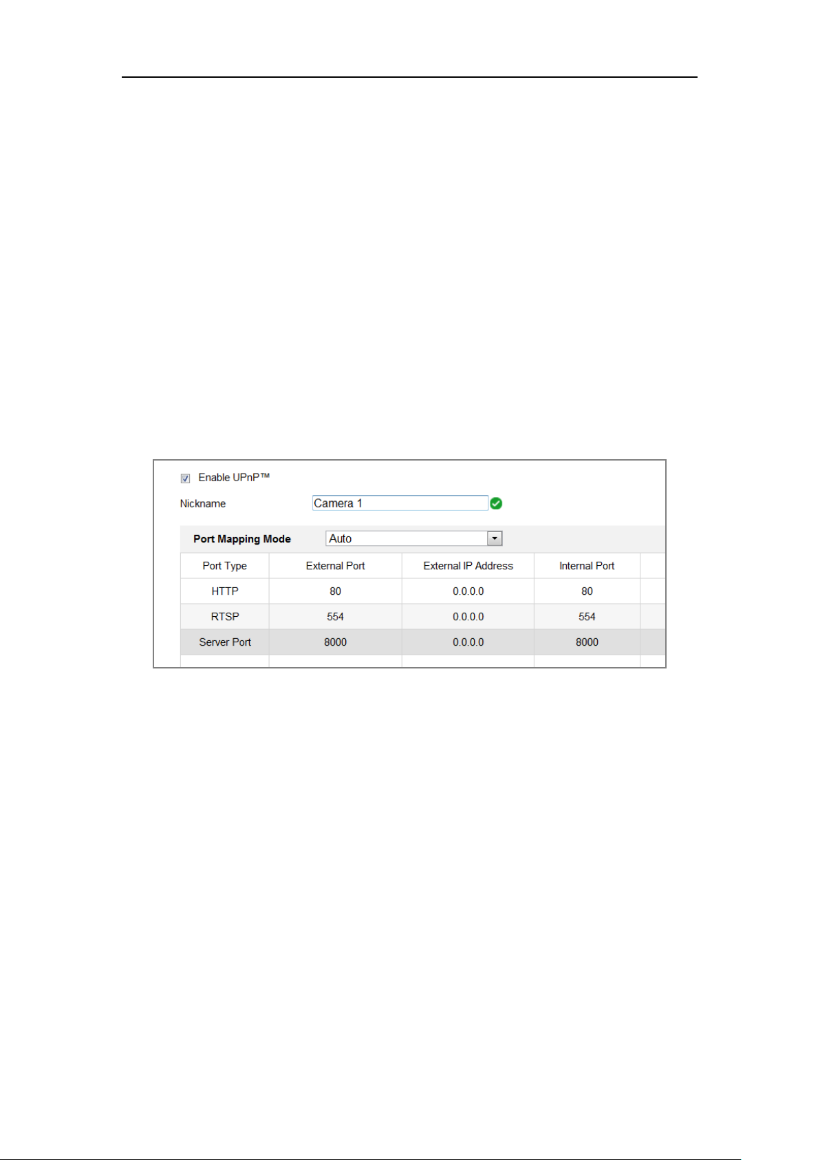
7.1.4 Configure NAT (Network Address Translation) Settings
Purpose:
NAT interface allows you to configure the UPnP™ parameters.
Universal Plug and Play (UPnP™) is a networking architecture that provides
compatibility among networking equipment, software and other hardware devices.
The UPnP protocol allows devices to connect seamlessly and to simplify the
Page 58
Dual-Lens People Counting Camera User Manual
50
implementation of networks in the home and corporate environments.
With the function enabled, you don’t need to configure the port mapping for each port,
and the camera is connected to the Wide Area Network via the router.
Steps:
1. Enter the NAT settings interface. Configuration > Network > Basic Settings >
NAT.
2. Check the checkbox to enable the UPnP™ function.
3. Choose a nickname for the camera, or you can use the default name.
4. Select the port mapping mode. Manual and Auto are selectable. And for manual
port mapping, you can customize the value of the external port.
5. Click Save to save the settings.
Figure 7-5 UPnP Settings
7.2 Configure Advanced Settings
Purpose:
You can configure the parameters, including FTP, Email, HTTPS, QoS, 802.1x, etc.,
by following the instructions in this section.
7.2.1 Configuring FTP Settings
Purpose:
You can configure the FTP server related information to enable the uploading of the
captured pictures to the FTP server. The captured pictures can be triggered by events
Page 59

Dual-Lens People Counting Camera User Manual
51
or a timing snapshot task.
Steps:
1. Enter the FTP Settings interface: Configuration > Network > Advanced
Settings > FTP.
Figure 7-6 FTP Settings
2. Input the FTP address and port.
3. Configure the FTP settings; and the user name and password are required for the
FTP server login.
For your privacy and to better protect your system against security risks, we
strongly recommend the use of strong passwords for all functions and
network devices. The password should be something of your own choosing
(using a minimum of 8 characters, including at least three of the following
categories: upper case letters, lower case letters, numbers and special
characters) in order to increase the security of your product.
Proper configuration of all passwords and other security settings is the
responsibility of the installer and/or end-user.
4. Set the directory structure and picture filing interval.
Directory: In the Directory Structure field, you can select the root directory,
Page 60

Dual-Lens People Counting Camera User Manual
52
parent directory and child directory. When the parent directory is selected, you
have the option to use the Device Name, Device Number or Device IP for the
name of the directory; and when the Child Directory is selected, you can use the
Camera Name or Camera No. as the name of the directory.
5. Check the Upload Picture checkbox to enable the function.
Upload Picture: To enable uploading the captured picture to the FTP server.
Anonymous Access to the FTP Server (in which case the user name and
password won’t be required.): Check the Anonymous checkbox to enable the
anonymous access to the FTP server.
Note: The anonymous access function must be supported by the FTP server.
6. Click Save to save the settings.
7.2.2 Configuring Email Settings
Purpose:
The system can be configured to send an Email notification to all designated receivers
if an alarm event is detected, e.g., motion detection event, video loss, video tampering,
etc.
Before you start:
Please configure the DNS Server settings under Configuration > Network > Basic
Settings > TCP/IP before using the Email function.
Steps:
1. Enter the TCP/IP Settings (Configuration > Network > Basic Settings >
TCP/IP) to set the IPv4 Address, IPv4 Subnet Mask, IPv4 Default Gateway and
the Preferred DNS Server.
Note: Please refer to Section 7.1.1 Configuring TCP/IP Settings for detailed
information.
2. Enter the Email Settings interface: Configuration > Network >Advanced
Settings > Email.
3. Configure the following settings:
Page 61

Dual-Lens People Counting Camera User Manual
53
Sender: The name of the email sender.
Sender’s Address: The email address of the sender.
SMTP Server: IP address or host name (e.g., smtp.263xmail.com) of the SMTP
Server.
SMTP Port: The SMTP port. The default TCP/IP port for SMTP is 25 (not
secured). And the SSL SMTP port is 465.
Email Encryption: None, SSL, and TLS are selectable. When you select SSL or
TLS and disable STARTTLS, e-mails will be sent after encrypted by SSL or TLS.
The SMTP port should be set as 465 for this encryption method. When you select
SSL or TLS and enable STARTTLS, emails will be sent after encrypted by
STARTTLS, and the SMTP port should be set as 25.
Note: If you want to use STARTTLS, make sure that the protocol is supported by
your e-mail server. If you check the Enable STARTTLS checkbox when the
protocol is not supported by your e-mail sever, your e-mail will not be encrypted.
Attached Image: Check the checkbox of Attached Image if you want to send
emails with attached alarm images.
Interval: The interval refers to the time between two actions of sending attached
pictures.
Authentication (optional): If your email server requires authentication, check
this checkbox to use authentication to log in to this server and input the login user
name and password.
For your privacy and to better protect your system against security risks, we
strongly recommend the use of strong passwords for all functions and
network devices. The password should be something of your own choosing
(using a minimum of 8 characters, including at least three of the following
categories: upper case letters, lower case letters, numbers and special
characters) in order to increase the security of your product.
Proper configuration of all passwords and other security settings is the
Page 62

Dual-Lens People Counting Camera User Manual
54
responsibility of the installer and/or end-user.
The Receiver table: Select the receiver to which the email is sent. Up to 3
receivers can be configured.
Receiver: The name of the user to be notified.
Receiver’s Address: The email address of user to be notified.
Figure 7-7 Email Settings
4. Click Save to save the settings.
7.2.3 Platform Access
Purpose:
Platform access provides you an option to manage the devices via platform.
Steps:
1. Enter the Platform Access settings interface: Configuration > Network >
Advanced Settings > Platform Access
2. Check the checkbox of Enable to enable the platform access function of the
Page 63

Dual-Lens People Counting Camera User Manual
55
device.
3. Select the Platform Access Mode.
Note: Hik-Connect is an application for mobile devices. With the App, you can
view live image of the camera, receive alarm notification and so on.
If you select Platform Access Mode as Hik-Connect,
1) Click and read "Terms of Service" and "Privacy Policy" in pop-up window.
2) Create a verification code or change the verification code for the camera.
Note:
• The verification code is required when you add the camera to Hik-Connect
app.
• For more information about the Hik-Connect app, refer to Hik-Connect
Mobile Client User Manual.
4. You can use the default server address. Or you can check the Custom checkbox
on the right and input a desired server address.
5. Click Save to save the settings.
7.2.4 HTTPS Settings
Purpose:
HTTPS provides authentication of the web site and its associated web server, which
Page 64

Dual-Lens People Counting Camera User Manual
56
protects against Man-in-the-middle attacks. Perform the following steps to set the port
number of https.
E.g., If you set the port number as 443 and the IP address is 192.168.1.64, you may
access the device by inputting https://192.168.1.64:443 via the web browser.
Steps:
1. Enter the HTTPS settings interface. Configuration > Network > Advanced
Settings > HTTPS.
2. Check the checkbox of Enable to enable the function.
3. Create the self-signed certificate or authorized certificate.
Create the self-signed certificate
(1) Select Create Self-signed Certificate as the Installation Method.
(2) Click Create button to enter the creation interface.
Figure 7-8 Create Self-signed Certificate
(3) Enter the country, host name/IP, validity and other information.
(4) Click OK to save the settings.
Note: If you already had a certificate installed, the Create Self-signed
Certificate is grayed out.
Create the authorized certificate
(1) Select Create the certificate request first and continue the installation as
the Installation Method.
(2) Click Create button to create the certificate request. Fill in the required
information in the popup window.
(3) Download the certificate request and submit it to the trusted certificate
Page 65

Dual-Lens People Counting Camera User Manual
57
authority for signature.
(4) After receiving the signed valid certificate, import the certificate to the
device.
4. There will be the certificate information after your successfully creating and
installing the certificate.
Figure 7-9 Installed Certificate
5. Click the Save button to save the settings.
7.2.5 Configuring QoS Settings
Purpose:
QoS (Quality of Service) can help solve the network delay and network congestion by
configuring the priority of data sending.
Steps:
1. Enter the QoS Settings interface: Configuration > Network > Advanced
Settings > QoS
Figure 7-10 QoS Settings
2. Configure the QoS settings, including Video/Audio DSCP, Event/Alarm DSCP
Page 66

Dual-Lens People Counting Camera User Manual
58
and Management DSCP.
The valid value range of the DSCP is 0 to 63. The bigger the DSCP value is, the
higher the priority is.
Note: DSCP refers to the Differentiated Service Code Point; and the DSCP value
is used in the IP header to indicate the priority of the data.
3. Click Save to save the settings.
Note: A reboot is required for the settings to take effect.
7.2.6 Configuring 802.1X Settings
Purpose:
The IEEE 802.1X standard is supported by the network cameras, and when the feature
is enabled, the camera data is secured and user authentication is needed when
connecting the camera to the network protected by the IEEE 802.1X.
Before you start:
The authentication server must be configured. Please apply and register a user name
and password for 802.1X in the server.
For your privacy and to better protect your system against security risks, we
strongly recommend the use of strong passwords for all functions and network
devices. The password should be something of your own choosing (using a
minimum of 8 characters, including at least three of the following categories:
upper case letters, lower case letters, numbers and special characters) in order to
increase the security of your product.
Proper configuration of all passwords and other security settings is the
responsibility of the installer and/or end-user.
Steps:
1. Enter the 802.1X Settings interface, Configuration > Network > Advanced
Settings > 802.1X
Page 67

Dual-Lens People Counting Camera User Manual
59
Figure 7-11 802.1X Settings
2. Check the Enable IEEE 802.1X checkbox to enable the feature.
3. Configure the 802.1X settings, including Protocol, EAPOL version, User Name,
Password and Confirm.
Note: The EAPOL version must be identical with that of the router or the switch.
4. Enter the user name and password to access the server.
5. Click Save to finish the settings.
Note: A reboot is required for the settings to take effect.
7.2.7 Configuring HTTP Listening
Purpose:
The camera can send alarm information to the destination IP or host name via HTTP
protocol. If the network is disconnected, the data can be uploaded to the destination IP
or host name after the network connection is normal.
Before you start:
The destination IP or host name should support the HTTP protocol to receive the
alarm information.
Steps:
1. Enter the HTTP Listening interface, Configuration > Network > Advanced
Settings > Listening.
Page 68

Dual-Lens People Counting Camera User Manual
60
Figure 7-12 HTTP Listening
2. Enter the desired destination IP or host name, URL and port.
3. You can click Test to test whether the entered IP address or host name are valid.
4. Or you can click Default to reset the destination IP or host name.
Page 69

Dual-Lens People Counting Camera User Manual
61
Chapter 8 Video/Audio Settings
8.1 Configuring Video Settings
Steps:
1. Enter the Video Settings interface, Configuration > Video/Audio > Video
Figure 8-1 Video Settings
2. Select the Stream Type of the camera to main stream (normal) or sub-stream.
Notes: The main stream is usually for recording and live view with good
bandwidth, and the sub-stream can be used for live view when the bandwidth is
limited.
3. You can customize the following parameters for the selected stream type.
Video Type:
Select the stream type to video stream, or video & audio composite stream. The
audio signal will be recorded only when the Video Type is Video & Audio.
Resolution:
Select the resolution of the video output.
Bitrate Type:
Page 70

Dual-Lens People Counting Camera User Manual
62
Select the bitrate type to constant or variable.
Video Quality:
When bitrate type is selected as Variable, 6 levels of video quality are selectable.
Frame Rate:
Set the frame rate. The frame rate is to describe the frequency at which the video
stream is updated and it is measured by frames per second (fps). A higher frame
rate is advantageous when there is movement in the video stream, as it maintains
image quality throughout.
Max. Bitrate:
Set the max. bitrate from 32 to 16384 Kbps. The higher value corresponds to the
higher video quality, but the better bandwidth is required.
Note: The maximum limit of the max. bitrate value varies according to different
camera platforms. For certain cameras, the maximum limit is 8192 Kbps or 12288
Kbps.
Max. Average Bitrate:
When you set a maximum bitrate, its corresponding recommended maximum
average bitrate will be shown in the Max. Average Bitrate box. You can also set the
maximum average bitrate manually from 32 Kbps to the value of the set maximum
bitrate.
Profile:
Basic profile, Main Profile, and High Profile for coding are selectable.
I Frame Interval:
Set I Frame Interval from 1 to 400.
Smoothing:
It refers to the smoothness of the stream. The higher value of the smoothing is, the
better fluency of the stream will be, though, the video quality may not be so
satisfactory. The lower value of the smoothing is, the higher quality of the stream
will be, though it may appear not fluent.
4. Click Save to save the settings.
Note:
Page 71

Dual-Lens People Counting Camera User Manual
63
The video parameters vary according to different camera models. Refer to the actual
display page for camera functions.
Page 72

Dual-Lens People Counting Camera User Manual
64
Chapter 9 Image Settings
Purpose:
Follow the instructions in this chapter to configure the image parameters, including
display settings, and OSD settings.
9.1 Configuring Display Settings
Purpose:
Configure the image adjustment, exposure settings, day/night switch, backlight
settings, white balance, image enhancement, video adjustment, and other parameters
in display settings.
Note: The display parameters vary according to the different camera models. Please
refer to the actual interface for details.
Steps:
1. Enter the Display Settings interface, Configuration > Image > Display Settings.
Image Adjustment
Brightness describes bright of the image, which ranges from 1 to 100.
Sharpness describes the edge contrast of the image, which ranges from 1 to 100.
Exposure Settings
If the camera is equipped with the fixed lens, only Manual is selectable, and the
iris mode is not configurable.
The Exposure Time refers to the electronic shutter time, which ranges from 1 to
1/100,000s. Adjust it according to the actual luminance condition.
Gain of image can also be manually configured from 0 to 100. The bigger the
value is, the brighter would the image be, and the noise would also be amplified
to a larger extent.
Page 73

Dual-Lens People Counting Camera User Manual
65
Figure 9-1 Exposure Settings
Day/Night Switch
Day/Night Switch controls the status of supplement light.
Day, Night, Auto, and Scheduled-Switch are selectable for day/night switch.
Figure 9-2 Day/Night Switch
Day: the camera stays at day mode.
Night: the camera stays at night mode.
Auto: the camera switches between the day mode and the night mode according
to the illumination automatically. The sensitivity ranges from 0 to 7, the higher
the value is, the easier the mode switches. The filtering time refers to the interval
time between the day/night switch. You can set it from 5s to 120s.
Scheduled-Switch: Set the start time and the end time to define the duration for
day/night mode.
Image Enhancement
Digital Noise Reduction: DNR reduces the noise in the video stream. OFF,
Normal and Expert are selectable. Set the DNR level from 0 to 100 in Normal
Mode.
Video Adjustment
Video Standard: 50 Hz and 60 Hz are selectable. Choose according to the
different video standards; normally 50 Hz for PAL standard and 60 Hz for NTSC
standard.
Page 74

Dual-Lens People Counting Camera User Manual
66
Capture Mode: It’s the selectable video input mode to meet the different
demands of field of view and resolution.
9.2 Configuring OSD Settings
Purpose:
You can customize the camera name, time/date format, display mode, and OSD size
displayed on the live view.
Steps:
1. Enter the OSD Settings interface: Configuration > Image > OSD Settings.
2. Check the corresponding checkbox to select the display of camera name, date or
week if required.
3. Edit the camera name in the text field of Camera Name.
4. Select from the drop-down list to set the time format and date format.
5. Select from the drop-down list to set the time format, date format, display mode,
OSD size and OSD color.
6. Configure the text overlay settings.
(1) Check the checkbox in front of the textbox to enable the on-screen display.
(2) Input the characters in the textbox.
7. Click Save to save the settings.
Page 75

Dual-Lens People Counting Camera User Manual
67
Chapter 10 Event Settings
10.1 Basic Events
You can configure the basic events by following the instructions in this section,
including video tampering, alarm input, alarm output, and exception, etc. These
events can trigger the linkage methods, such as Notify Surveillance Center, Send
Email, Trigger Alarm Output, etc.
Note: Check the checkbox of Notify Surveillance Center if you want the alarm
information to be pushed to PC or mobile client software as soon as the alarm is
triggered.
10.1.1 Configuring Video Tampering Alarm
Purpose:
You can configure the camera to trigger the alarm when the lens is covered and take
certain alarm response actions.
Steps:
1. Enter the video tampering Settings interface, Configuration > Event > Basic
Event > Video Tampering.
Page 76

Dual-Lens People Counting Camera User Manual
68
Figure 10-1 Video Tampering Alarm
2. Check Enable checkbox to enable the video tampering detection.
3. Set the video tampering area.
4. Set arming schedule for video tampering.
Task 1: Set the Arming Schedule
Figure 10-2 Arming Schedule
Page 77

Dual-Lens People Counting Camera User Manual
69
Steps:
1. Click Arming Schedule to edit the arming schedule.
2. Click on the time bar and drag the mouse to select the time period.
Figure 10-3 Arming Schedule
Note: Click on the selected time period, you can adjust the time period to the
desired time by either moving the time bar or input the exact time period.
3. (Optional) Click Delete to delete the current arming schedule, or click Save to
save the settings.
4. Move the mouse to the end of each day, a copy dialogue box pops up, and you
can copy the current settings to other days.
5. Click Save to save the settings.
Note: The time of each period can’t be overlapped. Up to 8 periods can be configured
for each day.
5. Check the checkbox to select the linkage method taken for the video tampering.
Task 2: Set the Linkage Method
Check the checkbox to select the linkage method. Audible Warning, Send Email,
Notify Surveillance Center, Upload to FTP/Memory Card/NAS, Trigger Channel and
Trigger Alarm Output are selectable. You can specify the linkage method when an
event occurs.
Page 78

Dual-Lens People Counting Camera User Manual
70
Figure 10-4 Linkage Method
Note: The linkage methods vary according to the different camera models.
Audible Warning
Trigger the audible warning locally. And it only supported by the device that
have the audio output.
Notify Surveillance Center
Send an exception or alarm signal to remote management software when an event
occurs.
Send Email
Send an email with alarm information to a user or users when an event occurs.
Note: To send the Email when an event occurs, please refer to Section 7.2.3 to
complete Email setup in advance.
Upload to FTP/Memory Card/NAS
Capture the image when an alarm is triggered and upload the picture to a FTP
server.
Notes:
● Set the FTP address and the remote FTP server first. Refer to Section 7.2.2
Configuring FTP Settings for detailed information.
● Go to Configuration > Storage > Schedule Settings> Capture > Capture
Parameters page, enable the event-triggered snapshot, and set the capture
interval and capture number.
● The captured image can also be uploaded to the available SD card or network
disk.
Page 79

Dual-Lens People Counting Camera User Manual
71
Trigger Channel
The video will be recorded when the motion is detected. You have to set the
recording schedule to realize this function. Please refer to Section 11.1 for
detailed information.
Trigger Alarm Output
Trigger one or more external alarm outputs when an event occurs.
Note: To trigger an alarm output when an event occurs, please refer to Section
10.1.3 Configuring Alarm Output to set the related parameters.
6. Click Save to save the settings.
10.1.2 Configuring Alarm Input
Steps:
1. Enter the Alarm Input Settings interface: Configuration > Event > Basic
Event > Alarm Input.
2. Choose the alarm input No. and the Alarm Type. The alarm type can be NO
(Normally Open) and NC (Normally Closed). Edit the name to set a name for the
alarm input (optional).
Figure 10-5 Alarm Input Settings
Page 80

Dual-Lens People Counting Camera User Manual
72
3. Click Arming Schedule to set the arming schedule for the alarm input.
4. Click Linkage Method and check the checkbox to select the linkage method
taken for the alarm input.
5. You can copy your settings to other alarm inputs.
6. Click Save to save the settings.
10.1.3 Configuring Alarm Output
Figure 10-6 Alarm Output Settings
Steps:
1. Enter the Alarm Output Settings interface: Configuration> Event > Basic
Event > Alarm Output.
2. Select one alarm output channel in the Alarm Output drop-down list. You can
also set a name for the alarm output (optional).
3. The Delay time can be set to 5sec, 10sec, 30sec, 1min, 2min, 5min, 10min or
Manual. The delay time refers to the time duration that the alarm output remains
in effect after alarm occurs.
Page 81

Dual-Lens People Counting Camera User Manual
73
7. Click Arming Schedule to enter the Edit Schedule Time interface.
4. You can copy the settings to other alarm outputs.
5. Click Save to save the settings.
10.1.4 Handling Exception
The exception type can be HDD full, HDD error, network disconnected, IP address
conflicted and illegal login to the cameras.
Steps:
1. Enter the Exception Settings interface: Configuration > Event > Basic Event >
Exception.
2. Check the checkbox to set the actions taken for the Exception alarm. Refer to
Section 0.
Figure 10-7 Exception Settings
3. Click Save to save the settings.
Page 82

Dual-Lens People Counting Camera User Manual
74
Chapter 11 Storage Settings
Before you start:
To configure record settings, please make sure that you have the network storage
device or local storage device configured.
11.1 Configuring Record Schedule
Purpose:
There are two kinds of recording for the cameras: manual recording and scheduled
recording. In this section, you can follow the instructions to configure the scheduled
recording. By default, the record files of scheduled recording are stored in the local
storage or in the network disk.
Steps:
1. Enter the Record Schedule Settings interface: Configuration > Storage >
Schedule Settings > Record Schedule.
Figure 11-1 Recording Schedule Interface
2. Check the checkbox of Enable to enable scheduled recording.
3. Click Advanced to set the camera record parameters.
Page 83

Dual-Lens People Counting Camera User Manual
75
Figure 11-2 Record Parameters
Pre-record: The time you set to start recording before the scheduled time or
the event. For example, if an alarm triggers recording at 10:00, and the
pre-record time is set as 5 seconds, the camera starts to record at 9:59:55.
The Pre-record time can be configured as No Pre-record, 5s, 10s, 15s, 20s, 25s,
30s or not limited.
Post-record: The time you set to stop recording after the scheduled time or the
event. For example, if an alarm triggered recording ends at 11:00, and the
post-record time is set as 5 seconds, the camera records until 11:00:05.
The Post-record time can be configured as 5s, 10s, 30s, 1 min, 2 min, 5 min or
10 min.
Stream Type: Select the stream type for recording.
Note: The record parameter configurations vary depending on the camera model.
4. Select a Record Type. The record type can be Continuous, Motion Detection,
Alarm, Motion | Alarm, Motion & Alarm, and Event.
Continuous
If you select Continuous, the video will be recorded automatically according
to the time of the schedule.
Record Triggered by Motion Detection
If you select Motion Detection, the video will be recorded when the motion is
detected.
Besides configuring the recording schedule, you have to set the motion
detection area and check the checkbox of Trigger Channel in the Linkage
Method of Motion Detection Settings interface.
Page 84

Dual-Lens People Counting Camera User Manual
76
Record Triggered by Alarm
If you select Alarm, the video will be recorded when the alarm is triggered
via the external alarm input channels.
Besides configuring the recording schedule, you have to set the Alarm Type
and check the checkbox of Trigger Channel in the Linkage Method of
Alarm Input Settings interface.
Record Triggered by Motion & Alarm
If you select Motion & Alarm, the video will be recorded when the motion
and alarm are triggered at the same time.
Besides configuring the recording schedule, you have to configure the settings
on the Motion Detection and Alarm Input Settings interfaces.
Record Triggered by Motion | Alarm
If you select Motion | Alarm, the video will be recorded when the external
alarm is triggered or the motion is detected.
Besides configuring the recording schedule, you have to configure the settings
on the Motion Detection and Alarm Input Settings interfaces.
Record Triggered by Events
If you select Event, the video will be recorded if any of the events is triggered.
Besides configuring the recording schedule, you have to configure the event
settings.
5. Select the record type, and click-and-drag the mouse on the time bar to set the
record schedule.
6. Click Save to save the settings.
11.2 Configure Capture Schedule
Purpose:
You can configure the scheduled snapshot and event-triggered snapshot. The captured
picture can be stored in the local storage or network storage.
Steps:
Page 85

Dual-Lens People Counting Camera User Manual
77
1. Enter the Capture Settings interface: Configuration > Storage > Storage
Settings > Capture.
Figure 11-3 Capture Configuration
2. Go to Capture Schedule tab to configure the capture schedule by click-and-drag
the mouse on the time bar. You can copy the record schedule to other days by
clicking the green copy icon on the right of each time bar.
3. Click Advanced to select stream type.
Figure 11-4 Advanced Setting of Capture Schedule
4. Click Save to save the settings.
5. Go to Capture Parameters tab to configure the capture parameters.
(1) Check the Enable Timing Snapshot checkbox to enable continuous
snapshot.
(2) Select the picture format, resolution, quality and capture interval.
Page 86

Dual-Lens People Counting Camera User Manual
78
(3) Check the Enable Event-triggered Snapshot checkbox to enable
event-triggered snapshot.
(4) Select the picture format, resolution, quality, capture interval, and capture
number.
Figure 11-5 Set Capture Parameters
6. Set the time interval between two snapshots.
7. Click Save to save the settings.
Page 87

Dual-Lens People Counting Camera User Manual
79
Chapter 12 Playback
Purpose:
This section explains how to view the remotely recorded video files stored in the
network disks or SD cards.
Steps:
1. Click Playback on the menu bar to enter playback interface.
Figure 12-1 Playback Interface
2. Select the date and click Search.
Figure 12-2 Search Video
3. Click to play the video files found on this date.
The toolbar on the bottom of Playback interface can be used to control playing
Page 88

Dual-Lens People Counting Camera User Manual
80
process.
Figure 12-3 Playback Toolbar
Table 12-1 Description of the buttons
Button
Operation
Button
Operation
Play
Capture a picture
Pause
/
Start/Stop clipping video
files
Stop
/
Audio on and adjust
volume/Mute
Speed down
Download
Speed up
Playback by frame
/
Enable/Disable
digital zoom
Note: You can choose the file paths locally for downloaded playback video files and
pictures in Local Configuration interface.
You can also input the time and click to locate the playback point in the Set
playback time field. You can also click to zoom out/in the progress bar.
Figure 12-4 Set Playback Time
Figure 12-5 Progress Bar
The different colors of the video on the progress bar stand for the different video
types.
Figure 12-6 Video Types
Page 89

Dual-Lens People Counting Camera User Manual
81
Chapter 13 Picture
Click Picture to enter the picture searching interface. You can search, view, and
download the pictures stored in the local storage or network storage.
Notes:
Make sure HDD, NAS or memory card are properly configured before you
process the picture search.
Make sure the capture schedule is configured. Go to Configuration > Storage >
Schedule Settings > Capture to set the capture schedule.
Figure 13-1 Picture Search Interface
Steps:
1. Select the file type from the dropdown list. Continuous, Motion, Alarm, Motion |
Alarm, Motion & Alarm, Line Crossing, Intrusion Detection, and Scene Change
Detection are selectable.
2. Select the start time and end time.
3. Click Search to search the matched pictures.
4. Check the checkbox of the pictures and then click Download to download the
selected pictures.
Note:
Up to 4000 pictures can be displayed at one time.
Page 90

Dual-Lens People Counting Camera User Manual
82
Chapter 14 Application
Click Application to enter the statistics counting interface. You can search, view, and
download the counting data stored in the local storage or network storage.
Note: Application function varies according to the different camera models.
14.1 People Counting Statistics
After you enable the people counting function, you can view and download the people
counting data from application tab. To get more intuitional results, you can display the
data in different charts.
Steps:
1. Select the report type. Daily report, weekly report, monthly report, and annual
report are selectable.
Note: Daily report calculates the data on the date you selected; weekly report
calculates for the week your selected date belongs to; monthly report calculates
for the month your selected date belongs to; and the annual report calculates for
the year your selected date belongs to.
2. Select the statistics type. People Entered, and People Exited are selectable.
3. Select the start time, and click Counting.
Note: If you enable Data Per Stop, the camera counts the data when an alarm is
triggered. If not, the camera counts the scheduled uploading data.
The counting result displays in the statistic result area. Click Table, Bar Chart, or
Line Chart to display the result in different way.
Note: If you select table to display the statistics, there is an Export button to
export the data in an excel file.
Figure 14-1 People Counting
Page 91

Dual-Lens People Counting Camera User Manual
83
Appendix
Appendix 1 SADP Software Introduction
Description of SADP
SADP (Search Active Devices Protocol) is a kind of user-friendly and installation-free
online device search tool. It searches the active online devices within your subnet and
displays the information of the devices. You can also modify the basic network
information of the devices using this software.
Search active devices online
Search online devices automatically
After launch the SADP software, it automatically searches the online devices
every 15 seconds from the subnet where your computer locates. It displays the
total number and information of the searched devices in the Online Devices
interface. Device information including the device type, IP address and port
number, etc. will be displayed.
Figure A.1.1 Searching Online Devices
Note:
Device can be searched and displayed in the list in 15 seconds after it went
online; it will be removed from the list in 45 seconds after it went offline.
Search online devices manually
Page 92

Dual-Lens People Counting Camera User Manual
84
You can also click to refresh the online device list manually. The
newly searched devices will be added to the list.
You can click or on each column heading to order the information;
you can click to expand the device table and hide the network parameter panel on
the right side, or click to show the network parameter panel.
Modify network parameters
Steps:
1. Select the device to be modified in the device list and the network parameters of
the device will be displayed in the Modify Network Parameters panel on the
right side.
2. Edit the modifiable network parameters, e.g. IP address and port number.
3. Enter the password of the admin account of the device in the Admin Password
field and click to save the changes.
For your privacy and to better protect your system against security risks, we
strongly recommend the use of strong passwords for all functions and network
devices. The password should be something of your own choosing (using a
minimum of 8 characters, including at least three of the following categories:
upper case letters, lower case letters, numbers and special characters) in
order to increase the security of your product.
Proper configuration of all passwords and other security settings is the
responsibility of the installer and/or end-user.
Page 93

Dual-Lens People Counting Camera User Manual
85
Figure A.1.2 Modify Network Parameters
Page 94
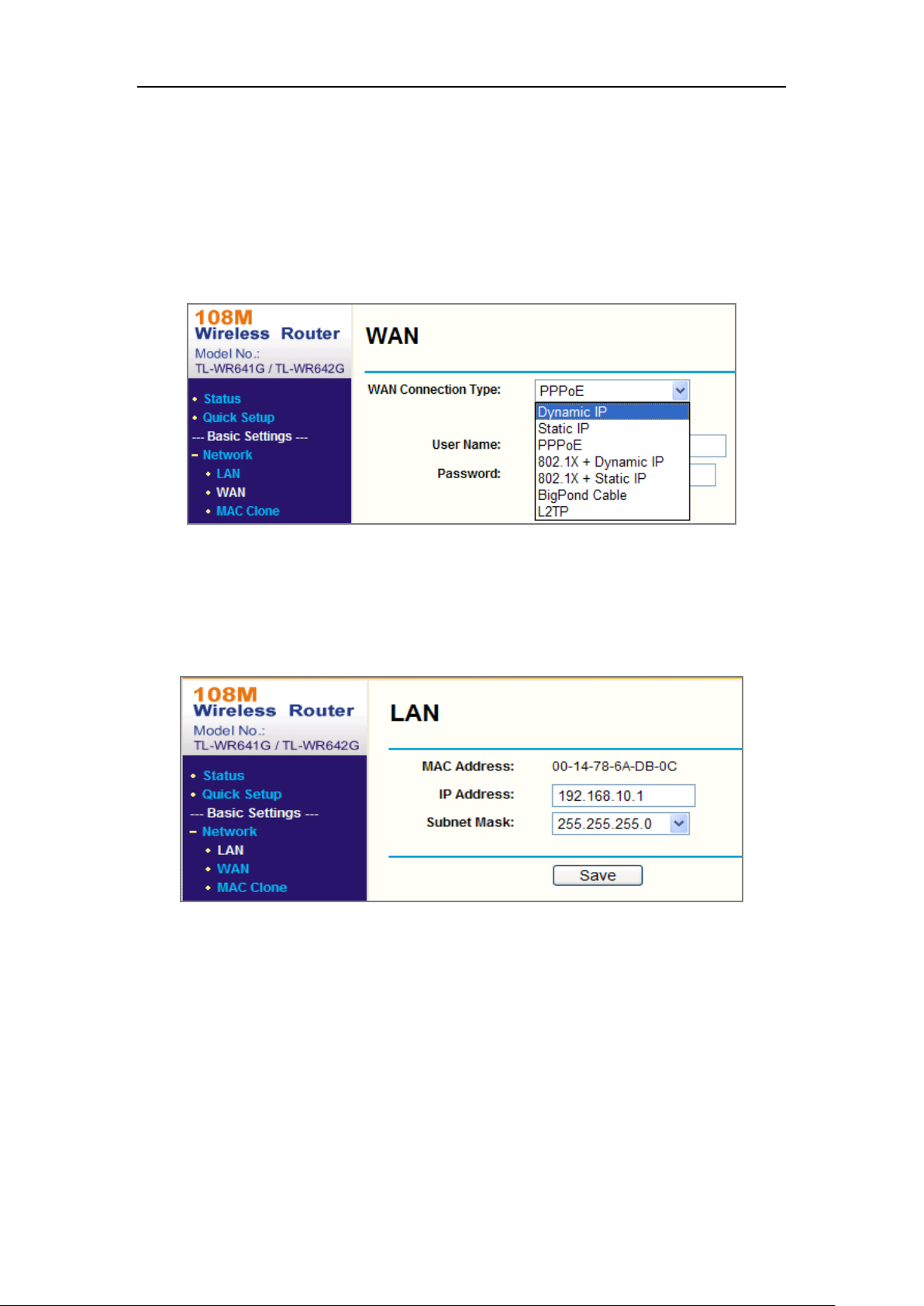
Dual-Lens People Counting Camera User Manual
86
Appendix 2 Port Mapping
The following settings are for TP-LINK router (TL-WR641G). The settings vary
depending on different models of routers.
Steps:
1. Select the WAN Connection Type, as shown below:
Figure A.2.1 Select the WAN Connection Type
2. Set the LAN parameters of the router as in the following figure, including IP
address and subnet mask settings.
Figure A.2.2 Set the LAN parameters
3. Set the port mapping in the virtual severs of Forwarding. By default, camera uses
port 80, 8000 and 554. You can change these ports value with web browser or
client software.
Example:
When the cameras are connected to the same router, you can configure the ports of
a camera as 80, 8000, and 554 with IP address 192.168.1.23, and the ports of
Page 95

Dual-Lens People Counting Camera User Manual
87
another camera as 81, 8001, 555, 8201 with IP 192.168.1.24. Refer to the steps as
below:
Steps:
1. As the settings mentioned above, map the port 80, 8000, 554 and 8200 for the
network camera at 192.168.1.23
2. Map the port 81, 8001, 555 and 8201 for the network camera at 192.168.1.24.
3. Enable ALL or TCP protocols.
4. Check the Enable checkbox and click Save to save the settings.
Figure A.2.3 Port Mapping
Note: The port of the network camera cannot conflict with other ports. For example,
some web management port of the router is 80. Change the camera port if it is the
same as the management port.
Page 96

Dual-Lens People Counting Camera User Manual
88
 Loading...