

Page 1

Network Security Control Panel User Manual
i
UD07466B
Network Security Control Panel
User Manual
Page 2

Network Security Control Panel User Manual
ii
User Manual
COPYRIGHT © 2017 Hangzhou Hikvision Digital Technology Co., Ltd.
ALL RIGHTS RESERVED.
Any and all information, including, among others, wordings, pictures, graphs are the properties
of Hangzhou Hikvision Digital Technology Co., Ltd. or its subsidiaries (hereinafter referred to be
“Hikvision”). This user manual (hereinafter referred to be “the Manual”) cannot be reproduced,
changed, translated, or distributed, partially or wholly, by any means, without the prior written
permission of Hikvision. Unless otherwise stipulated, Hikvision does not make any warranties,
guarantees or representations, express or implied, regarding to the Manual.
About this Manual
This Manual is applicable to Control Panel
The Manual includes instructions for using and managing the product. Pictures, charts, images
and all other information hereinafter are for description and explanation only. The information
contained in the Manual is subject to change, without notice, due to firmware updates or other
reasons. Please find the latest version in the company website
(http://overseas.hikvision.com/en/).
Please use this user manual under the guidance of professionals.
Trademarks Acknowledgement
and other Hikvision’s trademarks and logos are the properties of Hikvision in
various jurisdictions. Other trademarks and logos mentioned below are the properties of their
respective owners.
Legal Disclaimer
TO THE MAXIMUM EXTENT PERMITTED BY APPLICABLE LAW, THE PRODUCT DESCRIBED, WITH
ITS HARDWARE, SOFTWARE AND FIRMWARE, IS PROVIDED “AS IS”, WITH ALL FAULTS AND
ERRORS, AND HIKVISION MAKES NO WARRANTIES, EXPRESS OR IMPLIED, INCLUDING WITHOUT
LIMITATION, MERCHANTABILITY, SATISFACTORY QUALITY, FITNESS FOR A PARTICULAR
PURPOSE, AND NON-INFRINGEMENT OF THIRD PARTY. IN NO EVENT WILL HIKVISION, ITS
DIRECTORS, OFFICERS, EMPLOYEES, OR AGENTS BE LIABLE TO YOU FOR ANY SPECIAL,
CONSEQUENTIAL, INCIDENTAL, OR INDIRECT DAMAGES, INCLUDING, AMONG OTHERS,
DAMAGES FOR LOSS OF BUSINESS PROFITS, BUSINESS INTERRUPTION, OR LOSS OF DATA OR
DOCUMENTATION, IN CONNECTION WITH THE USE OF THIS PRODUCT, EVEN IF HIKVISION HAS
BEEN ADVISED OF THE POSSIBILITY OF SUCH DAMAGES.
REGARDING TO THE PRODUCT WITH INTERNET ACCESS, THE USE OF PRODUCT SHALL BE
WHOLLY AT YOUR OWN RISKS. HIKVISION SHALL NOT TAKE ANY RESPONSIBILITES FOR
ABNORMAL OPERATION, PRIVACY LEAKAGE OR OTHER DAMAGES RESULTING FROM CYBER
ATTACK, HACKER ATTACK, VIRUS INSPECTION, OR OTHER INTERNET SECURITY RISKS; HOWEVER,
HIKVISION WILL PROVIDE TIMELY TECHNICAL SUPPORT IF REQUIRED.
SURVEILLANCE LAWS VARY BY JURISDICTION. PLEASE CHECK ALL RELEVANT LAWS IN YOUR
JURISDICTION BEFORE USING THIS PRODUCT IN ORDER TO ENSURE THAT YOUR USE CONFORMS
THE APPLICABLE LAW. HIKVISION SHALL NOT BE LIABLE IN THE EVENT THAT THIS PRODUCT IS
USED WITH ILLEGITIMATE PURPOSES.
Page 3

Network Security Control Panel User Manual
iii
IN THE EVENT OF ANY CONFLICTS BETWEEN THIS MANUAL AND THE APPLICABLE LAW, THE
LATER PREVAILS.
0201001061111
Regulatory Information
FCC Information
Please take attention that changes or modification not expressly approved by the party
responsible for compliance could void the user’s authority to operate the equipment.
FCC compliance: This equipment has been tested and found to comply with the limits for a Class
B digital device, pursuant to part 15 of the FCC Rules. These limits are designed to provide
reasonable protection against harmful interference in a residential installation. This equipment
generates, uses and can radiate radio frequency energy and, if not installed and used in
accordance with the instructions, may cause harmful interference to radio communications.
However, there is no guarantee that interference will not occur in a particular installation. If this
equipment does cause harmful interference to radio or television reception, which can be
determined by turning the equipment off and on, the user is encouraged to try to correct the
interference by one or more of the following measures:
—Reorient or relocate the receiving antenna.
—Increase the separation between the equipment and receiver.
—Connect the equipment into an outlet on a circuit different from that to which the receiver is
connected.
—Consult the dealer or an experienced radio/TV technician for help.
This equipment should be installed and operated with a minimum distance 20cm between the
radiator and your body.
FCC Conditions
This device complies with part 15 of the FCC Rules. Operation is subject to the following two
conditions:
1. This device may not cause harmful interference.
2. This device must accept any interference received, including interference that may cause
undesired operation.
EU Conformity Statement
This product and - if applicable - the supplied accessories too are
marked with "CE" and comply therefore with the applicable harmonized
Page 4
Network Security Control Panel User Manual
iv
European standards listed under the R&TTE Directive 1999/5/EC, the EMC Directive
2004/108/EC, the LVD Directive 2006/95/EC, the RoHS Directive 2011/65/EU.
2012/19/EU (WEEE directive): Products marked with this symbol cannot
be disposed of as unsorted municipal waste in the European Union. For
proper recycling, return this product to your local supplier upon the
purchase of equivalent new equipment, or dispose of it at designated
collection points. For more information see: www.recyclethis.info
2006/66/EC (battery directive): This product contains a battery that
cannot be disposed of as unsorted municipal waste in the European
Union. See the product documentation for specific battery information.
The battery is marked with this symbol, which may include lettering to
indicate cadmium (Cd), lead (Pb), or mercury (Hg). For proper recycling,
return the battery to your supplier or to a designated collection point.
For more information see: www.recyclethis.info
Industry Canada ICES-003 Compliance
This device meets the CAN ICES-3 (B)/NMB-3(B) standards requirements.
This device complies with Industry Canada licence-exempt RSS standard(s). Operation is subject
to the following two conditions:
(1) this device may not cause interference, and
(2) this device must accept any interference, including interference that may cause undesired
operation of the device.
Le présent appareil est conforme aux CNR d'Industrie Canada applicables aux appareils
radioexempts de licence. L'exploitation est autorisée aux deux conditions suivantes :
(1) l'appareil ne doit pas produire de brouillage, et
(2) l'utilisateur de l'appareil doit accepter tout brouillage radioélectrique subi, même si le
brouillage est susceptible d'en compromettre le fonctionnement.
Under Industry Canada regulations, this radio transmitter may only operate using an antenna of
a type and maximum (or lesser) gain approved for the transmitter by Industry Canada. To reduce
potential radio interference to other users, the antenna type and its gain should be so chosen
Page 5
Network Security Control Panel User Manual
v
that the equivalent isotropically radiated power (e.i.r.p.) is not more than that necessary for
successful communication.
Conformément à la réglementation d'Industrie Canada, le présent émetteur radio peut
fonctionner avec une antenne d'un type et d'un gain maximal (ou inférieur) approuvé pour
l'émetteur par Industrie Canada. Dans le but de réduire les risques de brouillage radioélectrique
à l'intention des autres utilisateurs, il faut choisir le type d'antenne et son gain de sorte que la
puissance isotrope rayonnée équivalente (p.i.r.e.) ne dépasse pas l'intensité nécessaire à
l'établissement d'une communication satisfaisante.
This equipment should be installed and operated with a minimum distance 20cm between the
radiator and your body.
Cet équipement doit être installé et utilisé à une distance minimale de 20 cm entre le radiateur
et votre corps.
Safety Instruction
These instructions are intended to ensure that the user can use the product correctly to avoid
danger or property loss.
The precaution measure is divided into ‘Warnings’ and ‘Cautions’:
Warnings: Serious injury or death may be caused if any of these warnings are neglected.
Cautions: Injury or equipment damage may be caused if any of these cautions are neglected.
Warnings Follow these safeguards to
prevent serious injury or
death.
Cautions Follow these precautions to
prevent potential injury or
material damage.
Warnings:
Please adopt the power adapter which can meet the safety extra low voltage (SELV)
standard. The power consumption cannot be less than the required value.
Do not connect several devices to one power adapter as an adapter overload may cause
over-heating and can be a fire hazard.
When the product is installed on a wall or ceiling, the device should be firmly fixed.
To reduce the risk of fire or electrical shock, do not expose the indoor used product to rain
Page 6

Network Security Control Panel User Manual
vi
or moisture.
This installation should be made by a qualified service person and should conform to all the
local codes.
Please install blackouts equipment into the power supply circuit for convenient supply
interruption.
If the product does not work properly, please contact your dealer or the nearest service
center. Never attempt to disassemble the product yourself. (We shall not assume any
responsibility for problems caused by unauthorized repair or maintenance.)
Please do not look directly into the laser light within 6 meters because laser is hazardous to
humans.
Cautions:
Make sure the power supply voltage is correct before using the product.
Do not drop the product or subject it to physical shock. Do not install the product on
vibratory surface or places.
Do not expose it to high electromagnetic radiating environment.
Do not aim the lens at the strong light such as sun or incandescent lamp. The strong light
can cause fatal damage to the product.
The sensor may be burned out by a laser beam, so when any laser equipment is being used,
make sure that the surface of the sensor not be exposed to the laser beam.
For working temperature, please refer to the specification manual for details.
To avoid heat accumulation, good ventilation is required for a proper operating
environment.
While shipping, the product should be packed in its original packing.
Please use the provided glove when open up the product cover. Do not touch the product
cover with fingers directly, because the acidic sweat of the fingers may erode the surface
coating of the product cover.
Please use a soft and dry cloth when clean inside and outside surfaces of the product cover.
Do not use alkaline detergents.
Improper use or replacement of the battery may result in hazard of explosion. Please use
the manufacturer recommended battery type.
Page 7

1
Content
Chapter 1 System Introduction ____________________________________ 3
1.1 Overview ______________________________________________________ 3
1.2 System Definition _______________________________________________ 3
1.2.1 Partition _________________________________________________________ 3
1.2.2 Public Partition ____________________________________________________ 3
1.2.3 Zone ____________________________________________________________ 4
1.2.4 Zone Type ________________________________________________________ 4
1.2.5 Relay ____________________________________________________________ 6
1.2.6 User Operations ___________________________________________________ 6
Chapter 2 System Controlling _____________________________________ 8
2.1 Keypad Introduction _____________________________________________ 8
2.2 Keypad Indicator ________________________________________________ 9
2.2.1 Control Panel Start-up ______________________________________________ 9
2.2.2 Alarm Keypad Start-up ______________________________________________ 9
2.2.3 Buzzer Description ________________________________________________ 13
2.3 Keypad Operation Code _________________________________________ 14
Single Partition Mode _____________________________________________________ 14
Multi-Partitions Mode _____________________________________________________ 14
2.3.1 Device Initialization _______________________________________________ 15
2.3.2 Control Panel Arming and Disarming _________________________________ 15
2.3.3 Zone Bypass Operation ____________________________________________ 16
2.3.4 Instant Arming ___________________________________________________ 19
2.3.5 Stay Arming _____________________________________________________ 19
2.3.6 Force Arming ____________________________________________________ 20
2.3.7 Canceling Keypad Alarm____________________________________________ 23
2.3.8 Single-Zone Operation _____________________________________________ 26
2.3.9 Alarm Output Alarm _______________________________________________ 27
2.3.10 Emergency Alarm _________________________________________________ 28
2.3.11 Group Bypass ____________________________________________________ 29
2.3.12 System Status Query ______________________________________________ 30
2.3.13 Changing User Password via Master Code _____________________________ 32
2.3.14 Remote Control Operation __________________________________________ 32
2.3.15 Controlling Card-Swiping User _______________________________________ 35
2.3.16 Control Panel Programming Operation ________________________________ 38
2.3.17 Prompt Operation ________________________________________________ 39
2.3.18 LCD Backlight Control ______________________________________________ 40
2.3.19 Keypad Volume Adjusting __________________________________________ 41
2.3.20 Language Switch (Chinese/English) ___________________________________ 41
2.3.21 Zone Testing _____________________________________________________ 41
2.3.22 Test Report Manually Relaying _______________________________________ 42
2.3.23 Project Mode ____________________________________________________ 44
Page 8

Network Security Control Panel User Manual
2
2.3.24 Control Panel Soft Recovery _________________________________________ 45
2.3.25 Auto-Search _____________________________________________________ 45
2.3.26 Auto-Registration _________________________________________________ 46
2.3.27 Signal Strength Query _____________________________________________ 47
2.3.28 Keypad Locking and Unlocking ______________________________________ 47
Chapter 3 Trouble Shooting _____________________________________ 48
Page 9

Network Security Control Panel User Manual
3
Chapter 1 System Introduction
1.1 Overview
Network security control panel uses embedded microcontroller technology for zone
monitoring and system status detection. The alarm or status reports can be transmitted to
the central alarm monitoring station through programming. Multiple alarm types and
report transmission methods (telephone network, the Ethernet network, and the GPRS
wireless network) are supported. A mobile client is attached for key fobs such as pushing
alarm notifications or status reports and remote arming/disarming. The control panel is
deployed mainly in the security systems of shopping malls, stores, residences, apartments,
communities, and so on.
1.2 System Definition
1.2.1 Partition
Definition
Partition is an independent area divided from the security control panel.
Partitions are independent control system, and can provide arming/disarming
function respectively.
Usage
It is partitions that make it possible for users with different demands to share and
use a same intrusion alarm system. Users can disarm zones in one partition even
though zones in other partitions are in the arming status. Every system user can
be configured to have different permissions, and to operate any partition.
1.2.2 Public Partition
Definition
Public partition is considered a special one which can be shared to other
partitions. It is usually applied to manage or control the public area related with
other areas controlled by other partitions in one building.
Logic
The public partition is armed automatically when all partitions linked with the
Page 10

Network Security Control Panel User Manual
4
public partition are in the arming status.
The public partition is disarmed automatically when any of partitions linked with
the public partition is in the disarming status.
The user also can arm or disarm the public partition independently.
Limit
For the public partition of multiple security control panels, up to 2 other
partitions can be linked to it.
1.2.3 Zone
Definition
Zone is a basic concept in the security control panel system. It refers to a
protection area in the system, and is regarded as the maximum recognizable unit
to distinguish the alarm event. As a connection between the detector and the
security control panel, it determines whether to trigger an alarm according to the
resistance value of the alarm controller.
1.2.4 Zone Type
24-Hr Audible Alarm Zone
The detectors of this zone are in 24 hours’ alert condition, which will
not be affected by arming and disarming operation or be bypassed.
When the zone detects alarm events, the sound and light alarming
prompt will be triggered on the keyboard. The siren output will be
triggered when the siren is linked, meanwhile the generated event
report will be uploaded to the center receiver, and the zone alarm
status can be checked on the client. This zone type is generally applied
to emergency button, smoke detector and glass break detector.
24-Hr Silent Alarm Zone
The detectors of this zone are in 24 hours’ alert condition, which will
not be affected by arming and disarming operation or be bypassed.
When the zone detects alarm events, the sound and light alarming
prompt will be triggered on the keyboard. The siren output will be
triggered when the siren is linked, meanwhile the generated event
report will be uploaded to the center receiver, and the zone alarm
status can be checked on the client. This zone type is generally applied
to the sites equipped with emergency button (e.g. bank, jewelry
counter).
24-Hr Auxiliary alarm zone
The detectors of this zone are in 24 hours’ alert condition, which will
Page 11

Network Security Control Panel User Manual
5
not be affected by arming and disarming operation or be bypassed.
When the zone detects alarm events, the sound and light alarming
prompt will be triggered on the keyboard. The siren output will be
triggered when the siren is linked, meanwhile the generated event
report will be uploaded to the center receiver (the uploaded report is
different with the report of 24-Hr Audible Alarm Zone), and the zone
alarm status can be checked on the client. Generally, it is used to define
a zone with emergency button, or a zone used to monitor devices, such
as water detector or temperature sensor.
Fire Alarm Zone
The detectors of this zone are in 24 hours’ alert condition, which will
not be affected by arming and disarming operation or be bypassed.
When the zone detects alarm events, the sound and light alarming
prompt will be triggered on the keyboard. The siren output will be
triggered when the siren is linked, meanwhile the generated event
report will be uploaded to the center receiver (the uploaded report is
different with the report of 24-Hr Audible Alarm Zone), and the zone
alarm status can be checked on the client. This zone type is generally
used in the smoke detector.
Perimeter Zone/Instant Zone
When the system is armed, the detectors of this zone will be in alert
condition. The zone will be immediately triggered when it detects
alarm event, and the system will alarm instantly without any delay time.
When the system is disarmed, if the zone hasn’t recovered, a zone
alarm recovered report will be automatically reported to the center
receiver, and the zone turns to fault status. This zone type can be
assigned to all the detectors, especially the detectors that used to
protect doors and windows.
Entering/Exiting Delayed Zone
The system will provide exiting delay after performing the arming
operation. The zone will not alert during exiting delay and the detectors
of this zone will be in alert condition at the end of exiting delay. When
the system is in arm away or arm stay, it will provide enter delay when
the zone detects alarm event. Users must disarm the system by the end
of enter delay, if not, the zone alarm will be triggered. When the
system is in arm instant, the alarm will occur instantly after the zone
detects alarm event, and the system will not provide enter delay. Both
the exiting delay and enter delay can be programmable set. This zone
type is mainly used in entrance/exit route (e.g. front door/main
entrance), which is a key route to operate keyboard for users.
Page 12

Network Security Control Panel User Manual
6
Interior Follower Zone
After arming the system, if the delayed Zone is first triggered, the
system will provide an entry delay when the interior follower zone is
triggered. If not, the interior follower zone will trigger alarm instantly.
The delay parameters of interior follower zone are the same with the e
delayed zone. It is mostly set in the rest room or hall (e.g. motion
detector), which is a key place to operate keyboard for users.
Key Arming/Disarming Zone
When the zone detects the output of detector event, the partition
arming will be triggered, while the recovery of detector event will
trigger disarming of the partition. This zone type will not be affected by
arming and disarming, and also can’t be bypassed. The zone can’t
display the alarm status, but can show fault status if the detector hasn’t
recovered after performing the disarming operation.
1.2.5 Relay
Definition
Relay refers to a programmable relay output of the security control panel, and a
connection between the security control panel and the follow-up output device.
By linking the relay, the security control panel can send the system event to the
cascading device, so as to connect the external light, or enable or disable other
devices.
1.2.6 User Operations
Arming
When the arming turns on, the intrusion detector starts work normally and turn
on the intrusion detection. The zones and loops that under the arming status are
detected in real time.. Once the resistance value exceeds the threshold, the alarm
starts.
Away Arming
When all the people in the detection area leave, turn on the Away Arming mode
to turn on all zones in the system after the defined dwell time.
Instant Arming
When all the people in the detection area leave, turn on the Instant Arming mode
to turn on all zones in the system instantly.
Stay Arming
The people stays inside the detection area, turn on the Stay Arming mode to turn
on all the perimeter burglary detection (such as perimeter detector, magnetic
contacts, curtain detector in the balcony), at the meanwhile, the detectors inside
Page 13

Network Security Control Panel User Manual
7
the detection area are bypassed (such as PIR detectors). People can move inside
the area and not trigger alarm.
Disarming
If you want to turn off the arming of the detectors, you should disarm the system.
Then the zones that disarmed are not protected, even an event occurs and
triggers the detectors, and no alarm will be trigger by controller.
Bypass
You can bypass any zone to turn off the protection of it when some exception
occurs while other zones can work normally.
Bypass Recovering
You can recover the zone that is by passed to make it work normally and be
protected.
Group Bypass
You can bypass several zones to turn off the protection of them when some
exception occurs while other zones can work normally.
Group Bypass Recovering
You can recover the zones that are group bypassed to make them work normally
and be protected.
Page 14
Network Security Control Panel User Manual
8
Chapter 2 System Controlling
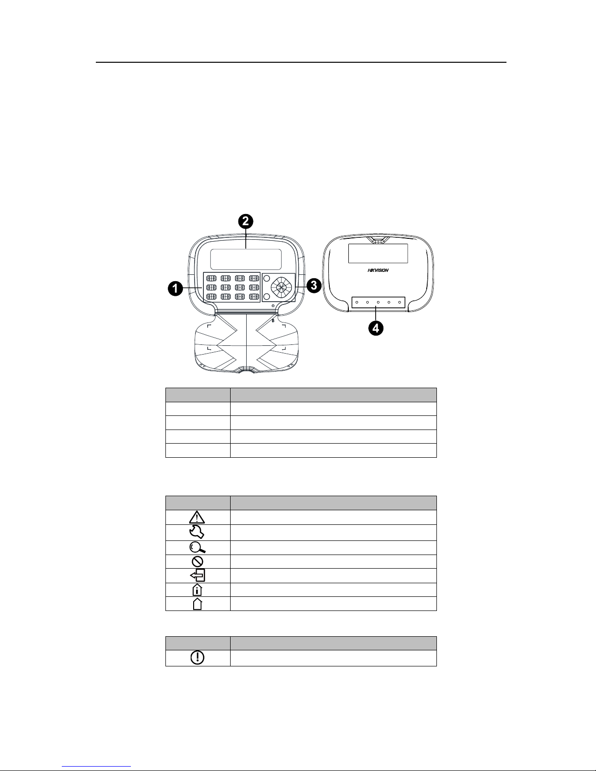
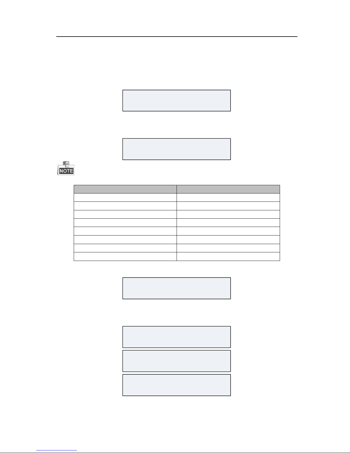
2.1 Keypad Introduction
Take DS-PK00 series keypad as an example. Please refer to the user manual based on the
corresponded model for other appearance.
No.
Description
1
Keypad
2
LED/LCD Screen
3
Control Panel
4
Indicator Bar
Control Panel
Button
Description
Panic Button
Programming Button
Search Button
Bypass Button
Exit Button
Stay Arming Button
Away Arming Button
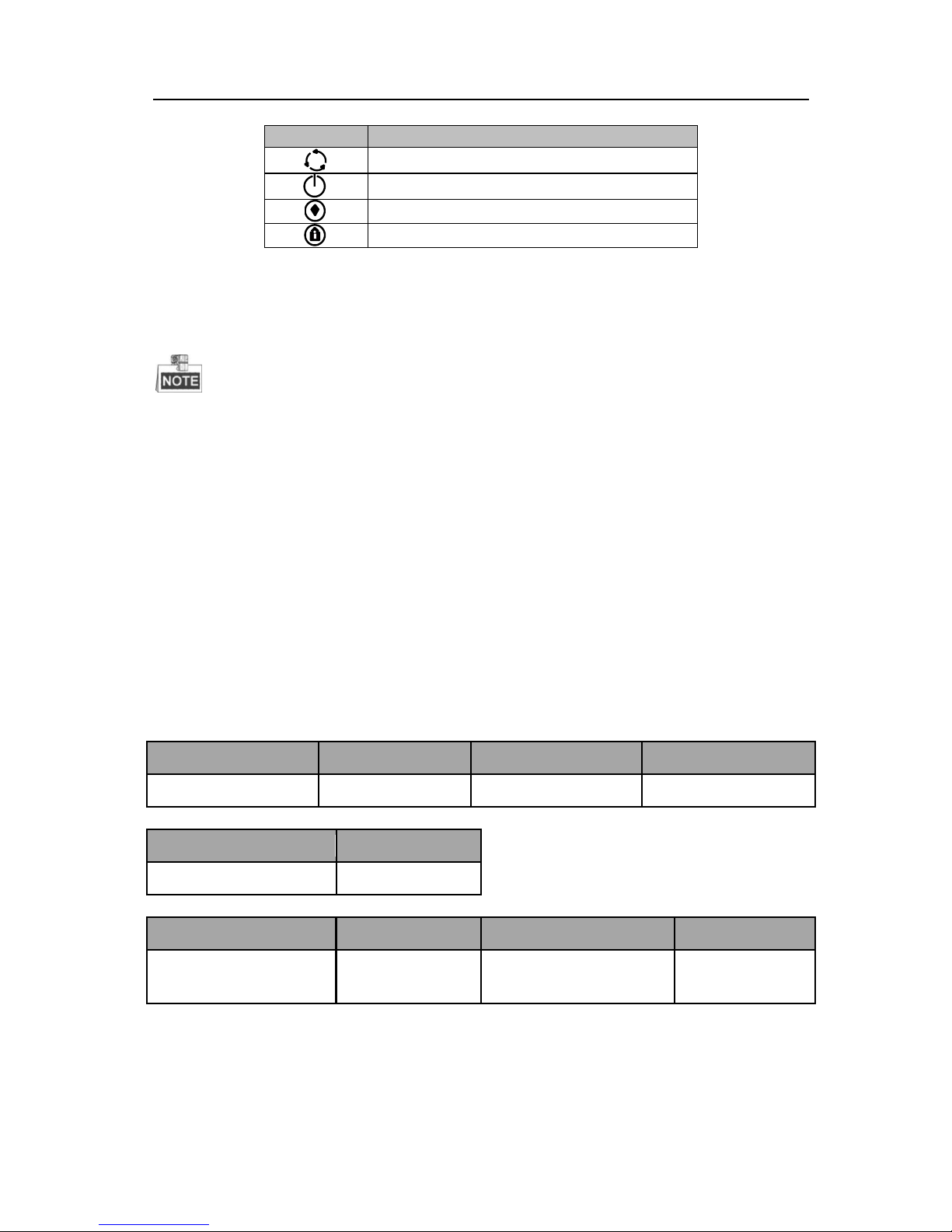
Indicator Bar
Button
Description
Status Indicator
Page 15
Network Security Control Panel User Manual
9
Button
Description
Operating Indicator
Power Indicator
Arming Indicator
Stay Arming Indicator
2.2 Keypad Indicator
For configuring the security control panel, you should restore the system of the control
panel after start-up.
2.2.1 Control Panel Start-up
The keypad registration will be completed in 32 seconds after the control panel being
power on. The system then will complete the start-up and enter the properly status of
working.
2.2.2 Alarm Keypad Start-up
The LED keypad will make continuously prompt tones if the keypad does not receive the
registration respond from the control panel in 20 seconds after it being power on. While
the registration is succeeded, the working status indicator will turn green.
Indicator Description
Status
Working Status
Indicator
Working Status
Indicator
Normal
Solid Green
System Fault
Solid Red
Power
Working Status
Indicator
Power On
Solid Green
Stay
Working Status
Indicator
Working Status
Indicator
Partition Perimeter
Disarmed
OFF
Partition System
Perimeter Armed
Orange
Page 16

Network Security Control Panel User Manual
10
Arm
Working Status
Indicator
Working Status
Indicator
Partition Armed
Solid Red
Partition System
Disarmed
Solid Green
Password Modifying
Flicking Green
Fob Code Matching
Flicking Green
Testing Mode
Solid Red
Programming
Flicking Green
OPERATING
Working Status
Indicator
Working Status
Indicator
Normal
Solid Green
Programming
Flicking Green
Password Modifying
Flicking Green
Fob Code Matching
Flicking Green
Engineering Mode
Solid Red
System Fault
Flicking Orange
LED Zone Indicator
Zone
Working Status
Indicator
Working Status
Indicator
Normal
OFF
Fault
Solid Red
Alarm
Flicking Red
Bypass
Solid Green
Zone Indicator under Engineering Mode (The corresponding zone indicator light will turn
orange when operating):
No.
Description
No.
Description
1
Off Hook
5
Sending CID Report
2
Dialing
6
Receiving Confirmation
3
Alarm Receiver Off Hook
7
Control Panel On Hook
4
Receiving Handshake
8
Alarm Receiver On Hook
Zone Indicator under Status Mode (The corresponding indicator light will be solid red if
there is any fault):
No.
Description
No.
Description
1
AC Current Interrupted
5
RS-485 Device Disconnected
2
Low Voltage of Storage
Battery
6
Wired Network Exception
3
Movement Prevention of
Control Panel Turning On
7
Wireless Network Exception
4
Telephone Line Disconnected
8
Reserved
Page 17
Network Security Control Panel User Manual
11
LCD Keypad Displayed Information
The system status display demonstration indicates the keypad display interface of system
status without any key pressing.
Powering on Display Demonstration
The display demonstration after powering on is shown below.
HIKVISION
System Status (normal) Display Demonstration
The display demonstration of system status (working properly) is shown below.
Global Keypad
SYS1D SYS2R SYS3A SYS4R
SYS5R SYS6R SYS7R SYS8R
The system status description is shown below.
System Status
Description
SYS1D
Partition1 Disarmed
SYS2R
Partition2 Ready
SYS3A
Partition3 Armed
SYS4R
Partition4 Ready
SYS5R
Partition5 Ready
SYS6R
Partition6 Ready
SYS7R
Partition7 Ready
SYS8R
Partition8 Ready
Partition Keypad
HIKVISION
System Fault
Keypad Standby Status Display Demonstration
The standby status display demonstration is shown below.
HIKVISION
SYS1D SYS2R SYS3A SYS4R
SYS5R SYS6R SYS7R SYS8R
V1.2.1 build 131211
2014.04.18 19:24:26
Page 18
Network Security Control Panel User Manual
12
The LCD keypad displays the version of the control panel and the time of operation.
Global Keypad Programming Status Display Demonstration
The programing status includes normal status and abnormal status. The demonstration is
shown below.
Normal Status
Programming...
Abnormal Status
Zone/Module Exception
Programming...
System Status (abnormal) Display Demonstration
Global Keypad
SYS1D SYS2R SYS3A SYS4R
SYS5R SYS6R SYS7R SYS8R
Partition Keypad
The system exception display of the partition keypad includes interfaces of alarm, fault and
bypass.
Zone Alarm
Zone Alarm
001 002 003 004 005 006
Zone Offline
Zone Offline
001 002 003 004 005 006
Zone Fault
Zone Fault
001 002 003 004 005 006
Zone Bypass
Zone Bypass
001 002 003 004 005 006
System Pacing Display Demonstration
The system pacing display demonstration is shown below.
Page 19
Network Security Control Panel User Manual
13
Work Test
001 002 003 004 005 006
System Fault Display Demonstration
The system fault display demonstration is shown below.
AC Power Off;
Low Battery Voltage;
Display Demonstration in Project Mode
The demonstration is shown below.
Network1: Connecting…
Network1: Connected
Network1: Sending Report…
Network1: Sending report
succeeded.
2.2.3 Buzzer Description
No.
Sound Prompt
Description
1
One Beep
Pressing keys prompt; The command is timed out or
the command is too long.
2
Two Beeps
Valid command. Uploading the report completed.
3
Five Beeps
Invalid command. Failed to upload the report in 60s.
4
Continuous Beeping for
Two Seconds
Fault Prompt
5
Slowly Continuous
Beeps
Entry/Exit Delay
6
Rapidly Continuous
Beeps
Entry/Exit Delay, less than 10s.
7
Rapid Beeps
Zone Alarm; The keyboard is not registered.
Page 20

Network Security Control Panel User Manual
14
No.
Sound Prompt
Description
8
Three Long Beeps and
Two Short Beeps
The tampering prevention of the keyboard is turned
on.
9
Three Beeps
Registering the keyboard completed.
10
One Beep In Two
Seconds
Two minutes before auto arming/disarming; One
minute before arming for temporary password.
11
Three Beeps In One
Second
One minute before auto arming/disarming; 15s
before arming for temporary password.
2.3 Keypad Operation Code
Single Partition Mode
Default Status: the control is in the single partition mode, that is, only partition 1 is enabled.
Multi-Partitions Mode
1) In the multi-partitions mode (equal to or more than 2 partitions), there are 2
modes for keypad operations: global keypad mode, and partition keypad mode.
Global Keypad Mode: In this mode, the user does not enter the partition. The
object of keypad operation is the whole system of the control panel.
Partition Keypad Mode: In this mode, the user enters the partition. The object of
keypad operation is the partition that the user enters.
When initializing the device, the partition 1 is enabled and the global keypad
mode is disabled by default. The global keypad enters the partition mode, and
cannot be switched into the global mode. The system will enable the global mode
automatically unless the partition except for partition 1 is enabled.
The command for entering partition is “*3n#”, in which the range of n is from 1 to
8, standing 8 partitions.
The command for exiting partition is “*#”.
2) Only the administrator and the installer have the permission to operate the global
keypad. On the global keypad, the administrator can view and operate all partitions and the
whole control panel system.
3) When operating on the partition keypad, the administrator can only operate the
partition which the keypad belongs to.
Page 21

Network Security Control Panel User Manual
15
2.3.1 Device Initialization
Function: The control panel can be recovered through the alarm keypad initialization.
Command:[Installer Password] + [*] + [8] + [9] + [#]
Demonstration:
E.g., the installer
password is 012345.
LCD Display
Press the installer
password: [0] [1] [2] [3]
[4] [5].
xxxxxx*89
Press [*] to enter the
working mode.
Press the device
initialization command:
[8] and [9].
Press [#] to confirm the
operation.
If the operation is successful,
Operation Succeeded
If the operation is failed,
Operation Failed
2.3.2 Control Panel Arming and Disarming
Function: The operation of control panel arming and disarming is the same. After the
operation is completed, the arming status of the control panel will be changed (the
status of arming will be exchanged into disarming), and vice versa.
Command:[User Password] + [#]
Page 22

Network Security Control Panel User Manual
16
Demonstration:
E.g., the user password
is 1234.
LCD Display
Arming: The current status is status of disarming.
Press the user
password: [1] [2] [3]
[4].
xxxx
Press [#], and the
status of disarming will
be changed into
arming.
If the operation is successful,
Operation Succeeded
If the operation is failed,
Operation Failed
Disarming: The current status is status of arming.
Press the user
password: [1] [2] [3]
[4].
xxxx
Press [#], and the
status of arming will be
changed into
disarming.
If the operation is successful,
Operation Succeeded
If the operation is failed,
Operation Failed
2.3.3 Zone Bypass Operation
Zone Bypass
Function: After bypassing a zone, all the alarm devices in this zone will be blocked.
Command:[User Password] + + [Zone No.] + [#]
Page 23

Network Security Control Panel User Manual
17
Demonstration:
E.g., the user password is
1234, and the zone No. Is
3.
LCD Display
Press the user password:
[1] [2] [3] [4].
xxxx Bypass 03
Press the bypass key:
.
Press the zone No.: [0]
[3].
Press [#] to confirm the
operation.
If the operation is successful,
Operation Succeeded
If the operation is failed,
Operation Failed
Multi-Zones Bypass Operation
Function: Through the multi-zones bypass operation, multiple zones can be bypassed
continuously, and all alarm devices in these zones will be blocked.
Command:
[User Password]
[Zone No.]
[Bypass]
[#]
+
++
15 Seconds
[Zone No.][Bypass] [#]
++
+
[Zone No.][Bypass] [#]
++
Page 24

Network Security Control Panel User Manual
18
Demonstration:
E.g., the user password is
1234, and the zone is No.
03, No. 04, and No. 05.
LCD Display
Press the user password:
[1] [2] [3] [4].
Note: For the continuous
bypass operation, the user
password is required to be
entered once only.
xxxx Bypass 03
Press the bypass key
to bypass zone No. 3.
Press the zone No.: [0] [3].
Press [#] to confirm the
operation.
Press the bypass key
to bypass zone No. 4.
Bypass 04
Press the zone No.: [0] [4].
Press [#] to confirm the
operation.
Press the bypass key
to bypass zone No. 5.
Bypass 05
Press the zone No.: [0] [5].
Press [#] to confirm the
operation.
If the operation is successful,
Operation Succeeded
If the operation is failed,
Page 25

Network Security Control Panel User Manual
19
Operation Failed
Multi-zones bypass/bypass recovery should be conducted in 15 seconds. For example,
bypass operations of the zone No. 04 and zone No. 05 should be completed in 15
seconds in the above demonstration.
2.3.4 Instant Arming
Function: The control panel can be set into the instant arming status via the keypad. The
instant arming means that the exiting delay is 0s.
Command: [User password]+[*]+[7]+[#]
Demonstration:
E.g., the user password is
1234.
LCD Display
Press the user password:
[1] [2] [3] [4].
xxxx*7
Press [*] to enter the
working mode.
Press [7], and the control
panel enters the instant
arming status.
Press [#] to confirm the
operation.
If the operation is successful,
Operation Succeeded
If the operation is failed,
Operation Failed
2.3.5 Stay Arming
Function: After the operation is completed, the partition will change the status of disarming
(current status) into arming immediately. The bypass supported zone of the partition will do
auto-bypass simultaneously.
Command: [User Password]+[*]+[4]+[#]
Page 26

Network Security Control Panel User Manual
20
Demonstration:
E.g., the user password is
1234.
LCD Display
Press the user password: [1]
[2] [3] [4].
xxxx*4
Press [*] to enter the
working mode.
Press [4], and the control
panel enters the stay
arming status.
Press [#] to confirm the
operation.
If the operation is successful,
Operation Succeeded
If the operation is failed,
Operation Failed
2.3.6 Force Arming
Force Normal(Away) Arming
Function: After the operation is completed, all the zones in fault status except the 24-hour
arming zones will be bypassed.
Command:[User Password]+ +[#]
Page 27

Network Security Control Panel User Manual
21
Demonstration:
E.g., the user password
is 1234, and the zone
number is 03.
LCD Display
Press the user password:
[1] [2] [3] [4].
xxxx Bypass 03
Press the bypass key:
.
Press [#] to confirm the
operation.
If the operation is successful,
Operation Succeeded
If the operation is failed,
Operation Failed
Force Instant Arming
Function: After the operation is completed, all the zones in fault status except the 24-hour
arming zones will be bypassed. The force instant arming means that the exiting delay is 0s.
Command: [User password]+[*]+[7]+ +[#]
Page 28

Network Security Control Panel User Manual
22
Demonstration:
E.g.,the user password
is 1234.
LCD Display
Press the user
password: [1] [2] [3]
[4].
xxxx*7
Press [*] to enter the
working mode.
Press[7], and the
control panel enters
the force instant
arming status.
Press the bypass key:
.
Press [#] to confirm the
operation.
If the operation is successful,
Operation Succeeded
If the operation is failed,
Operation Failed
Force Stay Arming
Function: After the operation is completed, all the zones in fault status except the 24-hour
arming zones will be bypassed. The bypass supported zone of the partition will do
auto-bypass simultaneously.
Command: [User Password]+[*]+[4]+ +[#]
Page 29

Network Security Control Panel User Manual
23
Demonstration:
E.g.,the user password
is 1234.
LCD Display
Press the user
password: [1] [2] [3]
[4].
xxxx*4
Press [*] to enter the
working mode.
Press [4], and the
control panel enters
the force stay arming
status.
Press the bypass key:
.
Press [#] to confirm the
operation.
If the operation is successful,
Operation Succeeded
If the operation is failed,
Operation Failed
2.3.7 Canceling Keypad Alarm
Function: When the alarm is triggered, it can be cancelled by the keypad. The alarm can be
cancelled both under the arming and disarming status.
Canceling Alarm under the Arming Status
Command: [User Password]+[*]+[1]+[#]
Page 30

Network Security Control Panel User Manual
24
Demonstration:
E.g., the user password is
1234.
LCD Display
Press the user password: [1]
[2] [3] [4].
xxxx*1
Press [*] to enter the working
mode.
Press [1] to cancel the alarm
under the arming status.
Press [#] to confirm the
operation.
If the operation is
successful,
Operation Succeeded
If the operation is failed,
Operation Failed
Canceling Alarm under the Disarming Status
Command 1: [User Password]+[*]+[1]+[#]
Page 31

Network Security Control Panel User Manual
25
Demonstration:
E.g., the user password is
1234.
LCD Display
Press the user password: [1]
[2] [3] [4].
xxxx*1
Press [*] to enter the
working mode.
Press [1] to cancel the
alarm under the disarming
status.
Press [#] to confirm the
operation.
If the operation is successful,
Operation Succeeded
If the operation is failed,
Operation Failed
Command 2:[*]+[1]+[#]
Page 32

Network Security Control Panel User Manual
26
Demonstration:
LCD Display
Press [*] to enter the
working mode.
*1
Press [1] to cancel the
alarm under the disarming
status.
Press [#] to confirm the
operation.
If the operation is successful,
Operation Succeeded
If the operation is failed,
Operation Failed
2.3.8 Single-Zone Operation
Single-Zone Arming and Disarming
Function: The operation of control panel arming and disarming is the same. After the
operation is completed, the arming status of the control panel will be changed (the status
of arming will be exchanged into disarming), and vice versa.
Command: [User Code] + [Project] +[n]+[n]+[n]+[#]
([n]+[n]+[n] refer to the zone No..)
Canceling Single-Zone Alarm
Function: When the alarm is triggered, it can be cancelled by the keypad. The alarm can be
cancelled both under the arming and disarming status. For the disarming status, the alarm
can be cancelled without the user code.
Canceling Alarm under the Arming Status
Command: [User Code] + [*] + [Project] +[n]+[n]+[n]+[#]
([n]+[n]+[n] refer to the zone No..)
Page 33

Network Security Control Panel User Manual
27
2.3.9 Alarm Output Alarm
Function: You can enable or disable the alarm output function by the alarm keypad.
Enabling Alarm Output
Command:[User Password] + [*] + [8] + [5] + [n]+[n]+[n] + [#]
([n]+[n]+[n] refer to the 3-digit alarm output channel No..)
Demonstration:
E.g., the user password is
1234, and the alarm output
channel No. is 001.
LCD Display
Press the user password: [1]
[2] [3] [4].
xxxx*85001
Press [*] to enter the
working mode.
Enable the alarm output by
pressing [8] [5].
Press the alarm output
channel No.: [0] [0] [1].
Press [#] to confirm the
operation.
If the operation is successful,
Operation Succeeded
If the operation is failed,
Operation Failed
Disable Alarm Output
Command:[User Password] + [*] + [8] + [6] + [n]+[n]+[n] + [#]
([n]+[n]+[n] refer to the 3-digit alarm output channel No..)
Page 34

Network Security Control Panel User Manual
28
Demonstration:
E.g., the user password is
1234, and the alarm
output channel No. is 001.
The alarm output function
of the alarm output
channel No. 001 has been
enabled.
LCD Display
Press the user password:
[1] [2] [3] [4].
xxxx*86001
Press [*] to enter the
working mode.
Disable the alarm output
by pressing [8] [6].
Press the alarm output
channel No.: [0] [0] [1].
Press [#] to confirm the
operation.
If the operation is successful,
Operation Succeeded
If the operation is failed,
Operation Failed
For the security control panel with bus extension module, up to 256 alarm output
channels can be supported, and thus the value range of nnn is from 001 to 256.
2.3.10 Emergency Alarm
Press and hold the key for 3 seconds or more. The emergency alarm will be triggered
after a double-beep sound.
Page 35

Network Security Control Panel User Manual
29
2.3.11 Group Bypass
Group Bypass
Function: After a partition is conducted with group bypass, all the alarm devices in
group-bypass supported zone of the partition will be blocked.
Command:[User Password] + [*] + [4] + [1] + [#]
Demonstration:
E.g., the user password is
1234.
LCD Display
Press the user password:
[1] [2] [3] [4].
xxxx*41
Press [*] to enter the
working mode.
Enable group bypass by
pressing [4] [1].
Press [#] to confirm the
operation.
If the operation is successful,
Operation Succeeded
If the operation is failed,
Operation Failed
Group Bypass Recovery
Function: After recovering the group bypass of a partition, all the alarm devices in
group-bypass supported zone of the partition will be revalidated.
Command: [User Password] + [*] + [4] + [2] + [#]
Page 36

Network Security Control Panel User Manual
30
Demonstration:
E.g., the user password is
1234.
LCD Display
Press the user password: [1]
[2] [3] [4].
xxxx*42
Press [*] to enter the
working mode.
Disable group bypass by
pressing [4] [2].
Press [#] to confirm the
operation.
If the operation is
successful,
Operation Succeeded
If the operation is failed,
Operation Failed
Group bypass operation and group bypass recovery operation are available to all group
bypass supported zones in the partition.
2.3.12 System Status Query
Function: Press key to search the current system default information of the
control panel.
In query mode, there are special meanings for the 8 indicators on the alarm keypad.
Page 37

Network Security Control Panel User Manual
31
No.
Description
No.
Description
1
AC Power Loss
5
Keypad Disconnection
2
Low Battery
6
Network Disconnection
3
Tampering Alarm Enabling
7
Wireless Network Exception
4
Telephone Line Disconnection
8
Expanstion Bus Exception
Demonstration:
E.g., the master code is 1111, the user
No. Is 001, and the new user password
is 5678.
LCD Display
Enter Password Changing Progress: [Master Code] + [*] + [0] +
[#]
Press the master code: [1] [1] [1] [1].
xxxx*0
Change Password via Master Code
Enter the User No.
Press [*] to enter the working mode.
Press [0] to enter the password
changing progress.
Press [#] to confirm the operation.
Appoint the User:[User No.] + [#]
Press the user No. whose password is
to be changed: [0] [0] [1].
xx
Change Password via Master Code
Enter the New Password
Press [#] to confirm the user.
Page 38

Network Security Control Panel User Manual
32
2.3.13 Changing User Password via Master Code
Function: You can change the user password of the keypad via the master code.
Command:
[Master Code] + [*] + [0] + [#]
[User No.] + [#]
[New Password] + [#]
[New Password] + [#]
The user password will be changed by the above four steps.
2.3.14 Remote Control Operation
Matching Codes between Control Panel and Remote Control
Function: You can match the codes of the remote control with ones of the control panel via
the keypad.
1. Enter the code matching mode.
Command: [User Password] + [ * ] + [ 9 ] + [ 1 ] + [Remote Control No.] + [ # ]
Enter New Password:[New Password] + [#]
Press the new password of the
appointed user: [5] [6] [7] [8].
xxxx
Change Password via Master Code
Enter the New Password Again
Press [#] to confirm the operation.
Confirm New Password:[New Password] + [#]
Press the new password of the
appointed user again: [5] [6] [7] [8].
xxxx
Press [#] to confirm the new password.
Page 39

Network Security Control Panel User Manual
33
Demonstration:
E.g., the user password is
1234, and the remote
control No. is 001.
LCD Display
Press the user password: [1]
[2] [3] [4].
xxxx*91001
Press [*] to enter the
working mode.
Press [9] [1] to enter the
code matching mode.
Press the remote control
No.: [0] [0] [1].
Press [#] to confirm the
operation.
If the operation is successful,
Operation Succeeded
If the operation is failed,
Operation Failed
2. Press any key of the keypad, and the code is matched. The keypad will exit the
code matching mode automatically.
Deleting Appointed Code-Matched Remote Control
Function: You can delete an appointed remote control which has matched the code with
the control panel.
Command: [User Password] + [ * ] + [ 9 ] + [ 0 ] + [ Remote Control No.] + [ # ]
Page 40

Network Security Control Panel User Manual
34
Demonstration:
E.g., the user password is
1234, and the remote
control No. is 001.
LCD Display
Press the user password:
[1] [2] [3] [4].
xxxx*91001
Press [*] to enter the
working mode.
Enter the mode for
deleting code matched
remote control by
pressing [9] [0].
Press the remote control
No.: [0] [0] [1].
Press [#] to confirm the
operation.
If the operation is successful,
Operation Succeeded
If the operation is failed,
Operation Failed
Deleting All Code-Matched Remote Control
Function: You can delete all remote controls which have matched code with the control
panel.
Command: [User Password] + [ * ] + [ 9 ] + [ 2 ] + [ # ]
Page 41

Network Security Control Panel User Manual
35
Demonstration:
E.g., the user password is
1234.
LCD Display
Press the user password:
[1] [2] [3] [4].
xxxx*92001
Press [*] to enter the
working mode.
Enter the mode for
deleting all code matched
remote controls by
pressing [9] [2].
Press [#] to confirm the
operation.
If the operation is successful,
Operation Succeeded
If the operation is failed,
Operation Failed
2.3.15 Controlling Card-Swiping User
Function: You can conduct configurations for the card-swiping user.
Matching the Card No. with the Control Panel
1. Enter the matching mode
Command: [Master Code] + [Project] + [10] + [User No.] + [#]
Page 42

Network Security Control Panel User Manual
36
Demonstration:
E.g., the master code is
1234, and the user No. is
001.
LCD Display
Press the master code: [1]
[2] [3] [4].
xxxxProject10001
Press [Project] to enter
the project mode.
Press [1] [0] to the mode
for entering the user’s
card No..
Press the user No.: [0] [0]
[1].
Press [#] to confirm the
operation.
If the operation is successful,
Operation Succeeded
If the operation is failed,
Operation Failed
2. Swipe the card, and the keypad will exit the matching mode automatically.
Deleting Appointed Matched Card
Command: [Master Code] + [Project] + [1] + [1] + [User No.] + [ # ]
Page 43

Network Security Control Panel User Manual
37
Demonstration:
E.g., the master code
is 1234, and the user
No. is 001.
LCD Display
Press the master
code: [1] [2] [3] [4].
xxxxProject11001
Press [Project] to
enter the project
mode.
Enter the mode for
deleting appointed
matched card by
pressing [1] [1].
Press the user No.: [0]
[0] [1].
Press [#] to confirm
the operation.
If the operation is successful,
Operation Succeeded
If the operation is failed,
Operation Failed
In the card matching mode, you can delete the appointed card by swiping the card.
Command: [Master Code] + [Project] + [1] + [2] + [ # ]
Deleting All Matched Card
Command: [Master Code] + [Project] + [1] + [5 ] + [User No.] + [ # ]
Page 44

Network Security Control Panel User Manual
38
Demonstration:
E.g., the master code is
1234, and the user No. is
001.
LCD Display
Press the master code:
[1] [2] [3] [4].
xxxxProject15001
Press [Project] to enter
the project mode.
Enter the mode for
deleting all matched
cards by pressing [1] [5].
Press the user No.: [0]
[0] [1].
Press [#] to confirm the
operation.
If the operation is successful,
Operation Succeeded
If the operation is failed,
Operation Failed
Exiting Card Matching (Card Deleting) Mode
Command: [*] + [ # ]
2.3.16 Control Panel Programming Operation
Function: The control panel can be configured via alarm keypad operation.
Entering Programming Mode
Command:[Installer Password] + [*] + [0] + [#]
Page 45

Network Security Control Panel User Manual
39
Demonstration:
E.g., the installer
password is 012345.
LCD Display
Enter the installer
password: [0] [1] [2] [3] [4]
[5].
xxxxxx*0
Press [*] to enter the
working mode.
Press [0] to enter the
programming mode of
control panel.
Press [#] to confirm the
operation.
If the operation is successful,
Operation Succeeded
Programming...
If the operation is failed,
Operation Failed
Exiting Programming Mode
Command:[*] +[#]
2.3.17 Prompt Operation
Enabling/Disabling Key Tone
Function: You can enable or disable the key tone via the keypad.
Command:[*] + [5] + [1] + [#]
Disabling Fault Prompt
Function: You can disable the fault alarm prompt via the keypad. It will prompt a new tone
if there is a new fault.
Command:[*] + [5] + [6] + [#]
Page 46

Network Security Control Panel User Manual
40
2.3.18 LCD Backlight Control
LCD Backlight Time Control
Function: The duration of enabling LCD backlight can be configured via the keypad.
Command:[*]+[5]+[2]+[n]+[n]+[n]+[#]
Demonstration:
E.g., the duration of
enabling LCD backlight is
15 seconds.
LCD Display
Press [*] to enter the
working mode.
*52015
Enter the LCD backlight
configuration mode by
pressing [5] [2].
Pressing the backlight-on
duration: [0] [1] [5].
Note: [0] [1] [5] means
15 seconds.
Press [#] to confirm the
operation.
If the operation is successful,
Operation Succeeded
If the operation is failed,
Operation Failed
[n][n][n] means the duration in which the backlight is on, and the value 999 means
that the backlight is normally on.
LCD Backlight off
Function: You can disable the LCD backlight via the keypad.
Command: [ * ] + [ 8 ] + [ # ]
Page 47

Network Security Control Panel User Manual
41
2.3.19 Keypad Volume Adjusting
Function: You can adjust the volume via the keypad.
Command: [*]+[6]+[n]+[#]
[n] means the volume value. The value 0 means mute and 9 means the maximum
volume. The larger the number, the louder the volume is.
You need to touch the keypad first to enable the adjusting function.
2.3.20 Language Switch (Chinese/English)
Function: You can switch the language (Chinese or English) via the keypad.
Display English
Command: [ * ] + [ 9 ] + [ 1 ] + [ 1 ] + [ # ]
Display Chinese
Command: [ * ] + [ 9 ] + [ 1 ] + [ 0 ] + [ # ]
2.3.21 Zone Testing
Function: The zone testing function is used for keypad debugging.
Command:[User Password] + [*] + [6] + [0] + [#]
Page 48

Network Security Control Panel User Manual
42
Demonstration:
E.g., the user password
is 1234.
LCD Display
Press the user
password: [1] [2] [3]
[4].
xxxx*60
Press [*] to enter the
working mode.
Press [6] [0] to enter
the zone testing mode.
Press [#] to confirm
the operation.
If the operation is successful,
Operation Succeeded
If the operation is failed,
Operation Failed
The function of zone testing is only available under the status of disarming and
non-fault of the zone. The system will do auto-arming in the zone testing mode without
reporting any CID log. The siren will start warning after the alarm is triggered and stop
warning if the alarm is dismissed.
If the zone is disarmed, it will exit the zone testing mode automatically.
2.3.22 Test Report Manually Relaying
Function: You can relay test report manually. One operation generates one test report. It is
used to test the communication between the control panel and center after installing the
system or during the inspection.
Command:[User Password] + [*] + [6] + [1] + [#]
Page 49

Network Security Control Panel User Manual
43
Demonstration:
E.g., the user password
is 1234.
LCD Display
Press the user
password: [1] [2] [3]
[4].
xxxx*61
Press [*] to enter the
working mode.
Relay test report
manually by pressing
[6] [1].
Press [#] to confirm
the operation.
If the operation is successful,
Operation Succeeded
If the operation is failed,
Operation Failed
Page 50

Network Security Control Panel User Manual
44
2.3.23 Project Mode
Function: You can enter the project mode, and configure the control panel via the keypad.
Entering Project Mode
Command:[User Password] + [Project] + [9]+ [0]+ [n] + [#]
Demonstration:
E.g., the user password is
1234, and you want to
configure the telephone
uploading mode.
LCD Display
Press the user password:
[1] [2] [3] [4].
xxxxProject*901
Press the project key
Project.
Press the control panel
debugging command: [9]
[0].
Press the uploading
mode: [n].
Note: Different values of
[n] refer to different
uploading modes.
Press [#] to confirm the
operation.
If the operation is successful,
Operation Succeeded
If the operation is failed,
Operation Failed
Exiting Project Mode
There are 3 options for exiting the project mode:
Hold and press the project key [Project].
Press [Status].
Press [*] [#].
Page 51

Network Security Control Panel User Manual
45
When the value of n is 1 or 2, it means telephone 1 or 2.
When the value of n is 3 or 4, it means network 1 or 2.
When the value of n is 5 or 6, it means GPRS center 1 or 2.
2.3.24 Control Panel Soft Recovery
Function: You can do the control panel soft recovery operation via the keypad. There is a
default value of the master code, which can control all partitions and be modified.
Command:[Master Code] + [*] + [6] + [8] + [#]
Demonstration:
E.g., the master code is
1234.
LCD Display
Press the master code:
[1] [2] [3] [4].
xxxx*68
Press [*] to enter the
working mode.
Press [6] [8] to do the
control panel soft
recovery operation.
Press [#] to confirm the
operation.
If the operation is successful,
Operation Succeeded
If the operation is failed,
Operation Failed
All unissued CID logs will not be reissued. Newly generated report will be issued after
system recovery.
The timer of the test report will not be cleared, and will remain the value before
recovery till the recovery processes being completed.
2.3.25 Auto-Search
Function: You can enter the auto-searching mode of the global keypad via the alarm
keypad.
Command:[Installer Password] + [*] + [8] + [2] + [#]
Page 52

Network Security Control Panel User Manual
46
Demonstration:
E.g., the installer
password is 012345.
LCD Display
Press the installer
password: [0] [1] [2] [3]
[4] [5].
xxxxx*82
Press [*] to enter the
working mode.
Press [8] [2] to enter the
auto-searching mode of
the global keypad.
Press [#] to confirm the
operation.
If the operation is successful,
Operation Succeeded
If the operation is failed,
Operation Failed
2.3.26 Auto-Registration
Function: You can enter the auto-registration mode of the global keypad via the alarm
keypad.
Command:[Installer Password] + [*] + [8] + [3] + [#]
Page 53

Network Security Control Panel User Manual
47
Demonstration:
E.g., the installer
password is 012345.
LCD Display
Press the installer
password: [0] [1] [2] [3] [4]
[5].
xxxxx*83
Press [*] to enter the
working mode.
Press [8] [3] to enter the
auto-registration mode of
the global keypad.
Press [#] to confirm the
operation.
If the operation is successful,
Operation Succeeded
If the operation is failed,
Operation Failed
2.3.27 Signal Strength Query
Function: You can view the 3G, 4G, and SUB-1G wireless signal strength via the alarm
keypad.
Command:[*] + [2] + [0] + [#]
2.3.28 Keypad Locking and Unlocking
If a user failed to operate for five times, the keypad will be locked for 30 seconds. During
the lock duration, the keypad backlight blinks and all of the key operations are invalid. The
keypad will be unlocked after 30 seconds.
Page 54

Network Security Control Panel User Manual
48
Chapter 3 Trouble Shooting
Q: What is the function of Project button of LCD keypad?
A: Project button has button switch function besides normal instruction button, such
as:
When sensor or module is abnormal, press and hold the Project button to switch to
other interfaces manually. When the sensor/module is abnormal or the keypad, press
the Project button once and the current display interface will be paused for 20s; press it
again to switch to the next LCD screen interface.
Q: How to manually switch to other abnormal interfaces when the LCD keypad displays
sensor/module is abnormal?
A:
1. Among the LCD keypad abnormal display interfaces, display interface of the sensor
alarm, module abnormal display interface are of first priority; the sensor abnormal
interface is of second priority, sensor bypass interface is of third priority.
2. If interfaces of different priority exist at same time, the system automatically displays
the interface of first priority.
3. The switch between interfaces of same priority: there are two ways to switch display
interface of the sensor alarm to sensor off-line display interface.
1) System auto-switch: The system will refresh automatically. If the current
display interface is accomplished and other interfaces of same priority exist,
system will auto switch to other interfaces.
2) Manually switch: Press the Project button continuously until it switches to
the interface to display.
4. Switch between interfaces of different priority: from sensor alarm interface to sensor
bypass interface:
Press and hold the Project button for multiple times until it switches to the interface to
display.
Q: What is the meaning of LCD keypad Arm/Disarm, Operate indicators?
A: LCD system keypad indicator:
1. The meaning of Arm/Disarm indicator (Red and Green) is shown below:
Working Status
Indicator Status
Working Status
Indicator Status
Enter programming
Green, Blink
Parameters
Initialization
Green, Blink
System Arming
Red, Normally On
System Disarming
Green, Normally On
2. The meaning of Operate indicator (Green) is shown below:
Page 55

Network Security Control Panel User Manual
49
Working Status
Indicator Status
Working Status
Indicator Status
Enter programming
Green, Blink
Parameters
Initialization
Green, Blink
System Abnormal
Green, Blink
System Normal
Green, Normally On
Q: What are the steps of LED keypad to program the control panel?
A:
1. In overall keypad programming mode, the program command is: {installer password} +
{*} + {0} + {#};
2. To view the configuring operation for alarm control panel, please refer to alarm keypad
configuring code;
For example: program user password 2#, the password has arm/disarm function, does
not send arming report, does not allow bypass, password is 5678, and the program
code is shown as follow:
Command Code Arming Type Password End
{0}{0}{2} {3} {5}{6}{7}{8} {#}
3. Set program command
There are 2 alert sound of correct or 5 alert sound of error and corresponding OSD
notices after each program command is over. When 5 alert sound of error is heard and
the screen displays Operation Failed, there is error in program command setting and
the user need to reset correct program command. When 2 alert sound of correct is
heard and the screen displays Operation Succeeded but the setting parameters are
not the parameters needed, you can operate according to program command once
again.
4. Exit program mode, the program command is: {*} + {#}.
Q: What is the meaning of LED keypad Arm/Disarm, Operate, Camera indicators?
A:
LED alarm keypad Arm/Disarm indicator:
Working Status
Indicator Status
Working Status
Indicator Status
Armed
Red, Normally On
Enter Programming
Green, Blink
Disarmed
Green, Normally On
Main Operator
Change Password
Green, Blink
LED alarm keypad Operate indicator:
Working Status
Indicator Status
Working Status
Indicator Status
Normal
Green, Normally On
Keypad Not Logged In
Red, Blink
System Error
Orange, Blink
Enter Programming
Green, Blink
Project
Red, Normally On
Change Password
Green. Blink
Page 56

Network Security Control Panel User Manual
50
LED alarm keypad Camera indicator:
Working Status
Indicator Status
Working Status
Indicator Status
Sensor Normal
Off
Sensor Error
Red, Normally On
Sensor Alarm
Red, Blink
Sensor Bypass
Green, Normally On
LED keypad Camera indicator under Project Mode:
No.
Description
No.
Description
1
Off-hook
5
Send CID Report
2
Dial
6
Receive Alert Sound
3
Alarm Connecter Disconnection
7
Control Panel Off-hook
4
Receive the Hand-shack Sound
8
Alarm Connector On-hook
LED keypad Camera indicator under Status Mode:
No.
Description
No.
Description
1
AC Power off
5
Keypad Off-line
2
Battery Low Voltage
6
Network Cable Off-line
3
Control Panel Tamper-proof On
7
No SIM Card
4
ADSL Cable Off-line
8
Reserved
Q: What is the meaning of LED keypad alert sound?
A: The meaning of LED keypad alert sound is as follows:
No.
Keypad Alert Sound
Description
1
1 Sound
Keypad Prompt, Error Operating Prompt
2
2 Sound
Correctly answered, report uploading
succeeded
3
5 Sound
Incorrectly answered, report uploading failed
in 60s
4
Last for 2s
Error Prompt
5
Intermittent Slow Sound,
Continuously
Enter/Exit Delay
6
Intermittent Rapid Sound,
Continuously
Enter/Exit Delay, 10s Left
7
Rapid Beep
Sensor Alarm, Keypad not logged in
Page 57

Network Security Control Panel User Manual
51
No.
Keypad Alert Sound
Description
8
3 Long 2 Short
Keypad Tamper-proof On
Q: How to remove alarm memory?
A: There are two situations of removing alarm memory as shown below:
1) Under disarming mode: Press {*} + {1} + {#} or {Password} + {*} + {1} + {#}.
2) Under arming mode: Press {Password} + {*} + {1} + {#}.
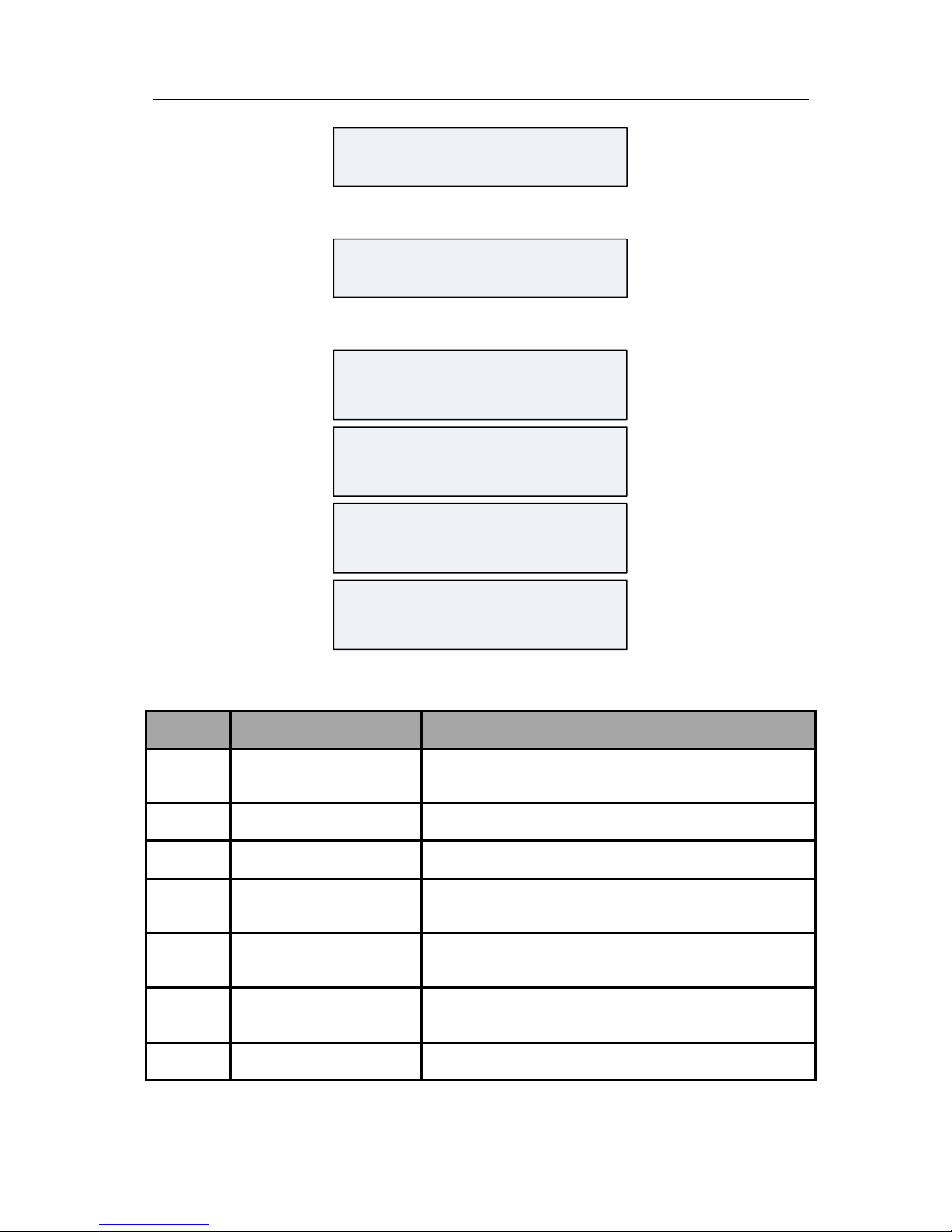
Q: How to input hexadecimal number?
A: Input hexadecimal number with {*} button and number button {0} ~ {5}.
Q: How to set LED keypad address?
A: Set LED keypad address with the DIP address of keypad.
Conversion Table
Hexadecimal Number
Corresponding Key
A
C
B
D
E
F
*0
*2
*1
*3
*4
*5
Page 58

Network Security Control Panel User Manual
52
DIP
Add. DIP
Add. DIP
Add. DIP
Add
.
21 3 4 5
ON
DIP
0
21 3 4 5
ON
DIP
1
21 3 4 5
ON
DIP
2
21 3 4 5
ON
DIP
3
21 3 4 5
DIP
ON
4
21 3 4 5
DIP
ON
5
21 3 4 5
DIP
ON
6
21 3 4 5
DIP
ON
7
21 3 4 5
ON
DIP
8
21 3 4 5
ON
DIP
9
21 3 4 5
ON
DIP
10
21 3 4 5
ON
DIP
11
21 3 4 5
DIP
ON
12
21 3 4 5
DIP
ON
13
21 3 4 5
DIP
ON
14
21 3 4 5
DIP
ON
15
21 3 4 5
ON
DIP
16
21 3 4 5
ON
DIP
17
21 3 4 5
ON
DIP
18
21 3 4 5
ON
DIP
19
21 3 4 5
DIP
ON
20
21 3 4 5
DIP
ON
21
21 3 4 5
DIP
ON
22
21 3 4 5
DIP
ON
23
21 3 4 5
ON
DIP
24
21 3 4 5
ON
DIP
25
21 3 4 5
ON
DIP
26
21 3 4 5
ON
DIP
27
21 3 4 5
DIP
ON
28
21 3 4 5
DIP
ON
29
21 3 4 5
DIP
ON
30
21 3 4 5
DIP
ON
31
Q: Why is it needed to input E at the end of keypad configured phone number?
A: Control panel can process phone number with 31 characters. Input number with 16
characters in each command address so that 2 addresses are needed for storage phone
number. However, the phone numbers are different in every place so the control panel
needs a special data bit to check if the phone number is complete. Character E ({*} {4})
is for checking if the phone number is complete.
For example: The first Alarm connecter phone number is 0571-88075998, user can input
the following command:
Command Address 460
0 5 7 1 8 8 0 7 5 9 9 8 E
For example: The first alarm connecter phone number is 17951-88075998, user can input
the following command:
Command Address 460
1 7 9 5 1 F F F 8 8 0 7 5 9 9
8
Command Address 461
E
Page 59

Network Security Control Panel User Manual
53
For example: The first alarm connecter phone number is 0571-88075998-8888, user can
input the following command:
Command Address 460
0 5 7 1 8 8 0 7 5 9 9 8 F F F
8
Command Address 461
8 8 8 E
Q: What are notes for setting password?
A: The password for each operator should be different; otherwise the setting will be failed.
For example, if the password of operator 1 is set to be 1234 hen password of operator 2
is also 1234, it will prompt to be error. In addition, the password of each operator
should be different from the control panel duress code of other operators; otherwise
the setting will be failed. For example if the password of operator No.3 is 3456 and the
password of operator No.4 is set to be3455 or 3457, it will prompt to be error.
Q: What are notes for setting duress code?
A:
1. The description of duress code is as follow:
Input duress code when the user is under duress, it will work as if the user inputs valid
password, but the system will auto-upload the alarm information. For example when a
criminal forces the user to disarm the alarm, user can input the control panel duress
code to disarm the system and upload the alarm information to the center
automatically and off the criminal’s guard.
2. Please note when setting duress code: duress code is the valid password with its last
number±1.
For example: Valid Password: 1234, Duress Code: 1235 and 1233.
For example: Valid Password: 1230, Duress Code: 1231 and 1239.
For example: Valid Password: 1239, Duress Code: 1230 and 1238.
3. Please take the following notes while using duress code:
While using duress code, it is needed to enable duress report firstly, as to program the
control panel duress report and delay. The programming command to enable Control
Panel Duress Report is as follow:
Command Address {4}{6}{4}
Enter Delay {3}
Exit Delay {6}
Siren Working Duration {2}
Control Panel Duress Report {1}
End {#}
Q: How to solve the problem of two LED keypad address being same?
A: When two LED keypad addresses are the same, the situation of two keypads demanding
bus communication at the same time will appear and cause conflict. The only solution is
to remove one keypad and reset the other keypad to an unused legal address. Restore
the control panel by processing program code ({Main Operator}{*}{6}{8}{#})
Page 60

Network Security Control Panel User Manual
54
Q: Why there is no Disarming Report?
A: To make sure the user has permission of Disarming Report, please refer to Operator
Configuration.
Q: What to do if the user cannot disarm after arming the system?
A: There are two different situations:
1. The user does not have permission to disarm, please contact the administrator.
2. Take the follow instructions when there is only one user in the system without
permission to disarm;
1) Initialize the hardware, restore the password of operator, main operator password
and permission, and then disarm with main operator. The initialization password of
operator is: 012345, the initialization password of main operator is: 1234, the
permission is: arm/disarm. There is arm/disarm report and bypass is permitted.
Please refer to FAQ of hardware initialization for more information about hardware
initialization.
2) The command code to restore factory parameters: {Password of operator} + {*} + {8}
+ {9} + {#}.
This method is not recommended because it will initialize all programming
contents.
Q: How to do the hardware initialization?
A: Control panel hardware initialization only initializes operator password: 012345 and main
operator password: 1234, main operator permission is arm/disarm. There are
arming/disarming report and allows bypass.
Steps:
1) Power off the control panel and open the cover;
2) Short the restore switch of the control panel with shorting nut or connection
cables;
3) Power on the control panel and power off it 10s later;
4) Please remove the shorting nut or connection cable on the restore switch;
5) Cover the control panel well;
6) Recharge the control panel;
Q: Why is there no response for keypad operational order but alert sound of error 10s
later?
A: It may be caused by follow situations:
1) Poor contact of the connection cable between LED keypad and the control panel,
please check if the cable is normal;
2) The LED keypad is considered as off-line in the communication. If there is other
keypad operates normal, process program command {Main Operator Password} +
{*} + {6} + {8} + {#}to restore it or power off the control panel and reboot.
Q: How does the control panel detect alternating current, storage battery, control panel
tamper-proof and ADSL cable?
A: The status of the control panel detection is as follows:
Page 61

Network Security Control Panel User Manual
55
1) The control panel detects AC power supply status once in a while;
2) The control panel detects storage battery status once in a while;
3) The control panel detects tamper-proof status once in a while;
4) The control panel detects ADSL cable status once in a while.
Q: The network is disconnected.
A:
1) Please check if the network status indicator of the board is normal on;
2) If the network status indicator is not normal on, please check if the network cable
connection is normal.
Q: What if the client cannot log in the device?
A: Troubleshoot according to the prompt.
Please check if the device IP Address and Port No. are correct. The device default IP
Address is: 192.0.0.64, and the Port No. is: 8000.
Please check if the user name and password to log in the control panel are correct. The
default user name is: admin, the word is: 12345.
Q: Why the control panel cannot communicate with the alarm center group?
A: The configuration of control panel communicating with the alarm center group is as
follows:
1) If the user communicates with the center via LAN: Configure parameters such as
monitoring IP, Port No., User Account and Communication Protocols of the remote
alarm center in Remote Configuration-> Others-> Network Center Configuration;
2) If the user communicates via dialing: Configure parameters such as phone number,
receiver identity account and communication protocols of the remote alarm center
in Remote Configuration-> Others-> Dialing Parameter Setting;
3) If the user communicates via Wi-Fi configure APN Name and Parameters of remote
alarm center in Remote Configuration-> Others-> WIFI Parameter Setting. The
parameters include monitoring IP, Port No., User Account and Communication
Protocol, etc.;
4) After setting dialing parameters, LAN parameters and WIFI parameters, configure
the uploading mode in Remote Configuration-> Uploading Mode Configuration
Q: How to configure the communication way of control panel and alarm center group?
A:
1. Center uploading mode supports at most 6 center groups, each center group divides in
main channel and 3 backup channels;
2. If the center group is enabled. Enable the center group before the use.
3. For example: The control panel needs to upload report to network alarm center 1 and
dialing alarm center1 and network alarm center 1 needs to upload report to network
alarm center 2 when it fails to upload it. The configurations are as follows:
1) Enable Group1 and Group2;
2) In the uploading mode configuration list, select N1 in center group 1 main channel,
Page 62

Network Security Control Panel User Manual
56
select N2 in backup channel 1, select T1 in Center group2 main channel.
3) Click Apply.
If the client is not opened, the user can realize communication with alarm center by
programming with keypad. For detailed operations please refer to program command
611~634.
Q: Why cannot it upload report and control after WIFI is enabled?
A: The follow situations may lead to WIWI connection failure:
1) No SIM Card or poor contact;
2) 3G module antenna is not normally connected or with poor signal;
3) WIFI parameter setting is incorrect;
4) SIM Card has no enough tariffs.
Page 63

 Loading...