

Page 1

Panic Alarm Station with Covert Camera
User Manual
Page 2

Panic Alarm Station with Covert Camera User Manual
ii
User Manual
COPYRIGHT © 2018 Hangzhou Hikvision Digital Technology Co., Ltd.
ALL RIGHTS RESERVED.
Any and all information, including, among others, wordings, pictures, graphs are the properties of
Hangzhou Hikvision Digital Technology Co., Ltd. or its subsidiaries (hereinafter referred to be
“Hikvision”). This user manual (hereinafter referred to be “the Manual”) cannot be reproduced,
changed, translated, or distributed, partially or wholly, by any means, without the prior written
permission of Hikvision. Unless otherwise stipulated, Hikvision does not make any warranties,
guarantees or representations, express or implied, regarding to the Manual.
About this Manual
This Manual is applicable to panic alarm station.
The Manual includes instructions for using and managing the product. Pictures, charts, images and
all other information hereinafter are for description and explanation only. The information
contained in the Manual is subject to change, without notice, due to firmware updates or other
reasons. Please find the latest version in the company website (http://overseas.hikvision.com/en/).
Please use this user manual under the guidance of professionals.
Trademarks Acknowledgement
and other Hikvision’s trademarks and logos are the properties of Hikvision in various
jurisdictions. Other trademarks and logos mentioned below are the properties of their respective
owners.
Legal Disclaimer
TO THE MAXIMUM EXTENT PERMITTED BY APPLICABLE LAW, THE PRODUCT DESCRIBED, WITH ITS
HARDWARE, SOFTWARE AND FIRMWARE, IS PROVIDED “AS IS”, WITH ALL FAULTS AND ERRORS,
AND HIKVISION MAKES NO WARRANTIES, EXPRESS OR IMPLIED, INCLUDING WITHOUT LIMITATION,
MERCHANTABILITY, SATISFACTORY QUALITY, FITNESS FOR A PARTICULAR PURPOSE, AND NONINFRINGEMENT OF THIRD PARTY. IN NO EVENT WILL HIKVISION, ITS DIRECTORS, OFFICERS,
EMPLOYEES, OR AGENTS BE LIABLE TO YOU FOR ANY SPECIAL, CONSEQUENTIAL, INCIDENTAL, OR
INDIRECT DAMAGES, INCLUDING, AMONG OTHERS, DAMAGES FOR LOSS OF BUSINESS PROFITS,
BUSINESS INTERRUPTION, OR LOSS OF DATA OR DOCUMENTATION, IN CONNECTION WITH THE USE
OF THIS PRODUCT, EVEN IF HIKVISION HAS BEEN ADVISED OF THE POSSIBILITY OF SUCH DAMAGES.
REGARDING TO THE PRODUCT WITH INTERNET ACCESS, THE USE OF PRODUCT SHALL BE WHOLLY
AT YOUR OWN RISKS. HIKVISION SHALL NOT TAKE ANY RESPONSIBILITES FOR ABNORMAL
OPERATION, PRIVACY LEAKAGE OR OTHER DAMAGES RESULTING FROM CYBER ATTACK, HACKER
ATTACK, VIRUS INSPECTION, OR OTHER INTERNET SECURITY RISKS; HOWEVER, HIKVISION WILL
PROVIDE TIMELY TECHNICAL SUPPORT IF REQUIRED.
SURVEILLANCE LAWS VARY BY JURISDICTION. PLEASE CHECK ALL RELEVANT LAWS IN YOUR
JURISDICTION BEFORE USING THIS PRODUCT IN ORDER TO ENSURE THAT YOUR USE CONFORMS
THE APPLICABLE LAW. HIKVISION SHALL NOT BE LIABLE IN THE EVENT THAT THIS PRODUCT IS USED
WITH ILLEGITIMATE PURPOSES.
IN THE EVENT OF ANY CONFLICTS BETWEEN THIS MANUAL AND THE APPLICABLE LAW, THE LATER
PREVAILS.
Page 3
Panic Alarm Station with Covert Camera User Manual
iii
Regulatory Information
FCC Information
Please take attention that changes or modification not expressly approved by the party responsible for compliance could void the
user’s authority to operate the equipment.
FCC compliance: This equipment has been tested and found to comply with the limits for a Class A digital device, pursuant to part 15
of the FCC Rules. These limits are designed to provide reasonable protection against harmful interference when the equipment is
operated in a commercial environment. This equipment generates, uses, and can radiate radio frequency energy and, if not installed
and used in accordance with the instruction manual, may cause harmful interference to radio communications. Operation of this
equipment in a residential area is likely to cause harmful interference in which case the user will be required to correct the
interference at his own expense.
FCC Conditions
This device complies with part 15 of the FCC Rules. Operation is subject to the following two conditions:
1. This device may not cause harmful interference.
2. This device must accept any interference received, including interference that may cause undesired operation.
EU Conformity Statement
This product and - if applicable - the supplied accessories too are marked with "CE" and comply therefore with the
applicable harmonized European standards listed under the EMC Directive 2014/30/EU, LVD Directive 2014/35/EU, the
RoHS Directive 2011/65/EU.
2012/19/EU (WEEE directive): Products marked with this symbol cannot be disposed of as unsorted municipal waste in
the European Union. For proper recycling, return this product to your local supplier upon the purchase of equivalent
new equipment, or dispose of it at designated collection points. For more information see: www.recyclethis.info
2006/66/EC (battery directive): This product contains a battery that cannot be disposed of as unsorted municipal waste
in the European Union. See the product documentation for specific battery information. The battery is marked with this
symbol, which may include lettering to indicate cadmium (Cd), lead (Pb), or mercury (Hg). For proper recycling, return
the battery to your supplier or to a designated collection point. For more information see: www.recyclethis.info
Industry Canada ICES-003 Compliance
This device meets the CAN ICES-3 (A)/NMB-3(A) standards requirements.
Page 4
Panic Alarm Station with Covert Camera User Manual
iv
Applicable Models
This manual is applicable to DS-PEA series panic alarm station.
Product
Model
Panic Alarm Station
DS-PEA1-N1, DS-PEA1-N2
Symbol Conventions
The symbols that may be found in this document are defined as follows.
Safety Instruction
The device should be used in compliance with local laws and electrical safety regulations. Refer to the
appropriate documentation for detailed information.
The input voltage should conform to IEC60950-1 standard: SELV (Safety Extra Low Voltage) and the
Limited Power Source (24 VAC/12 VDC). Refer to the appropriate documentation for detailed
information.
DO NOT connect multiple devices to one power adapter, to avoid over-heating or fire hazards caused
by overload.
Make sure the plug is properly connected to the power socket.
If smoke, odor, or noise arises from the device, immediately turn off the power, unplug the power
cable, and contact the service center.
Do not drop the device or subject it to physical shock.
Wipe the device gently with a clean cloth and a small quantity of ethanol, if necessary.
Do not aim the lens at the sun or any other bright light.
When any laser equipment is in use, make sure that the device lens is not exposed to the laser beam,
or it may burn out.
Do not expose the device to high electromagnetic radiation or extremely hot, cold, dusty, or damp
environments, the appropriate temperature is -40℃ to 60℃.
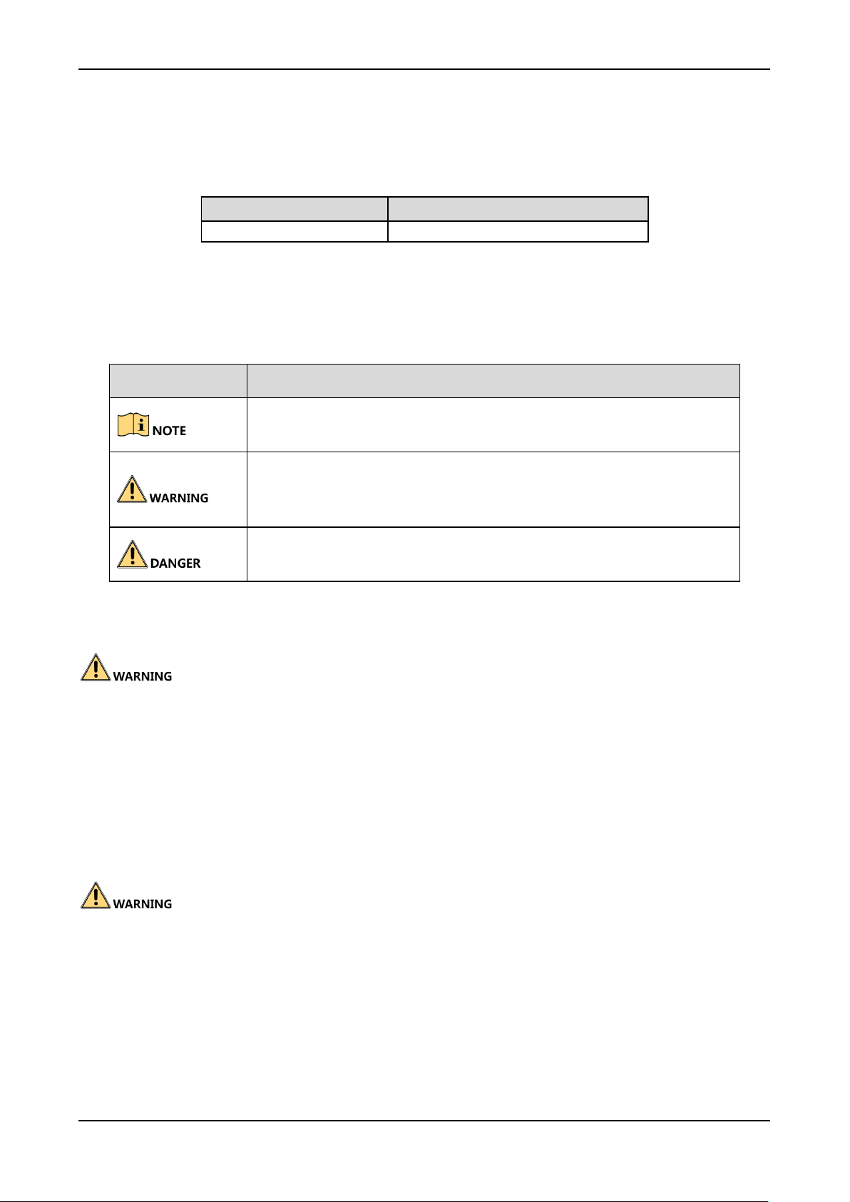
Symbol
Description
Provides additional information to emphasize or supplement
important points of the main text.
Indicates a potentially hazardous situation, which if not avoided,
could result in equipment damage, data loss, performance
degradation, or unexpected results.
Indicates a hazard with a high level of risk, which if not avoided, will
result in death or serious injury.
Page 5

Panic Alarm Station with Covert Camera User Manual
v
Place the device in a dry and well-ventilated environment.
Keep non-waterproof devices away from liquids.
Keep the device in original or similar packaging while transporting it.
A few device components (e.g., electrolytic capacitor) require regular replacement. The average
lifespan varies, so periodic checking is recommended. Contact your dealer for details.
Improper use or replacement of the battery may result in explosion hazard. Replace with the same or
equivalent type only. Dispose of used batteries in conformance with the instructions provided by the
battery manufacturer.
Never attempt to disassemble the device.
Page 6

Panic Alarm Station with Covert Camera User Manual
vi
Table of Content
Chapter 1 Overview .............................................................................................................................................................. 1
Description ....................................................................................................................................................................... 1
Key Features .................................................................................................................................................................... 1
Chapter 2 Appearance .......................................................................................................................................................... 2
Panic Alarm Station without Help Buttonn ...................................................................................................................... 2
Panic Alarm Station with Help Button.............................................................................................................................. 3
Chapter 3 Installation and Wiring .......................................................................................................................................... 4
Typical Application ........................................................................................................................................................... 4
Wiring Description ........................................................................................................................................................... 5
Network Wiring ..................................................................................................................................................... 6
Alarm Output Wiring ............................................................................................................................................ 6
Alarm Input Wiring (Normally Open) .................................................................................................................... 7
Power Supply Wiring ............................................................................................................................................. 8
Installation ....................................................................................................................................................................... 9
Installation Description ......................................................................................................................................... 9
Chapter 4 Device Remote Operation ................................................................................................................................... 10
Activation via SADP Tool ................................................................................................................................................ 10
Remote Operation via Client Software .......................................................................................................................... 11
Activation via Client Software ............................................................................................................................. 11
Add a Device ....................................................................................................................................................... 13
Zone Settings ...................................................................................................................................................... 14
Zone Event Settings ............................................................................................................................................. 16
Alarm Pop-up Window Settings .......................................................................................................................... 17
Broadcast Settings ......................................................................................................................................................... 18
Chapter 5 Remote Operation via iVMS-4200 ....................................................................................................................... 19
System Information Settings .......................................................................................................................................... 19
General Settings .................................................................................................................................................. 19
Timing Settings .................................................................................................................................................... 20
System Maintenance ........................................................................................................................................... 21
Log Searching ...................................................................................................................................................... 22
User Settings ....................................................................................................................................................... 23
Password Management ...................................................................................................................................... 25
Network Settings ........................................................................................................................................................... 25
General Network Parameters Settings ................................................................................................................ 25
Network Center Settings ..................................................................................................................................... 26
Call Center Settings ............................................................................................................................................. 27
Advanced Network Parameters Settings ............................................................................................................. 28
CMS Settings ....................................................................................................................................................... 29
Sip Settings .......................................................................................................................................................... 30
Storage Settings ............................................................................................................................................................. 31
HDD Information ` ............................................................................................................................................... 31
File Query ............................................................................................................................................................ 32
Alarm Settings ................................................................................................................................................................ 33
Zone Settings ...................................................................................................................................................... 33
Trigger Settings ................................................................................................................................................... 35
Calling Waiting Settings....................................................................................................................................... 35
Alarm Lamp Settings ........................................................................................................................................... 36
Voice Prompt Settings ......................................................................................................................................... 37
Image Settings ............................................................................................................................................................... 37
Video& Audio Settings ........................................................................................................................................ 37
OSD Settings........................................................................................................................................................ 38
Image Settings ..................................................................................................................................................... 39
Event Settings ................................................................................................................................................................ 40
Schedule Settings ................................................................................................................................................ 40
Camera Parameter Settings ........................................................................................................................................... 42
Video Parameter Settings ................................................................................................................................... 42
WDR Settings ...................................................................................................................................................... 43
Audio Detection ............................................................................................................................................................. 43
Page 7

Panic Alarm Station with Covert Camera User Manual
1
Chapter 1 Overview
Description
This series of panic alarm station with covert camera supports two-way audio communication. It is
equipped with a 2MP built-in covert camera. The device with help button or without help button
can be selected. It implements cascading communication via network cable wiring.
Key Features
Network, video and audio adaptive
Voice intercom, alarm video storage, video download and playback
Two RJ45 network interfaces, supports cascading communication
Video compression: H.264
Audio compression: G.711 and G726
Audio detection
Built-in 2MP 1080P IR HD wide angle camera; supports capture, record, and live view
Built-in high sensitivity microphone
Full-band speakers and pickups supports anti-breaking sound technology
Multiple network protocols: TCP/IP, SNMP, RTSP and SADP
Anti-electromagnetic interference, tamper-proof, explosion-proof, and anti-lightning
Page 8
Panic Alarm Station with Covert Camera User Manual
2
Chapter 2 Appearance
There are two types of the panic alarm stations: Panic alarm station without Help button and panic
alarm station with Help button.
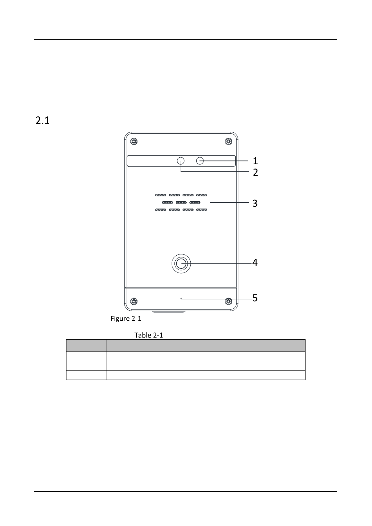
Panic Alarm Station without Help Buttonn
Panic Alarm Station without Help Button
Components Description
No.
Description
No.
Description
1
IR Light
4
Panic Button
2
Covert Camera
5
Microphone
3
Loudspeaker
Page 9
Panic Alarm Station with Covert Camera User Manual
3
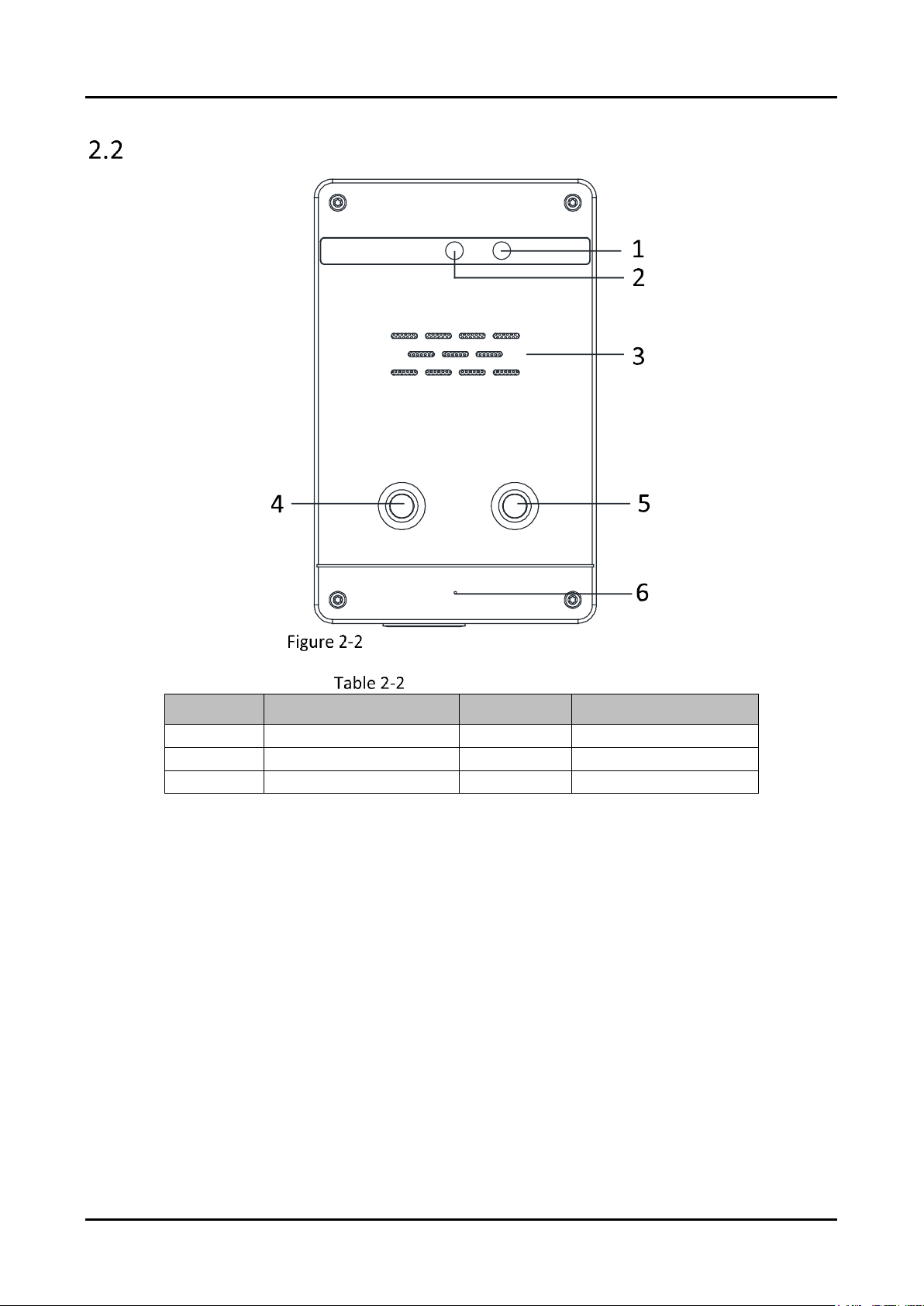
Panic Alarm Station with Help Button
Panic Alarm Station with Help Button
Components Description
No.
Description
No.
Description
1
IR Light
4
Panic Button
2
Covert Camera
5
Help Button
3
Loudspeaker
6
Microphone
Page 10
Panic Alarm Station with Covert Camera User Manual
4
Chapter 3 Installation and Wiring
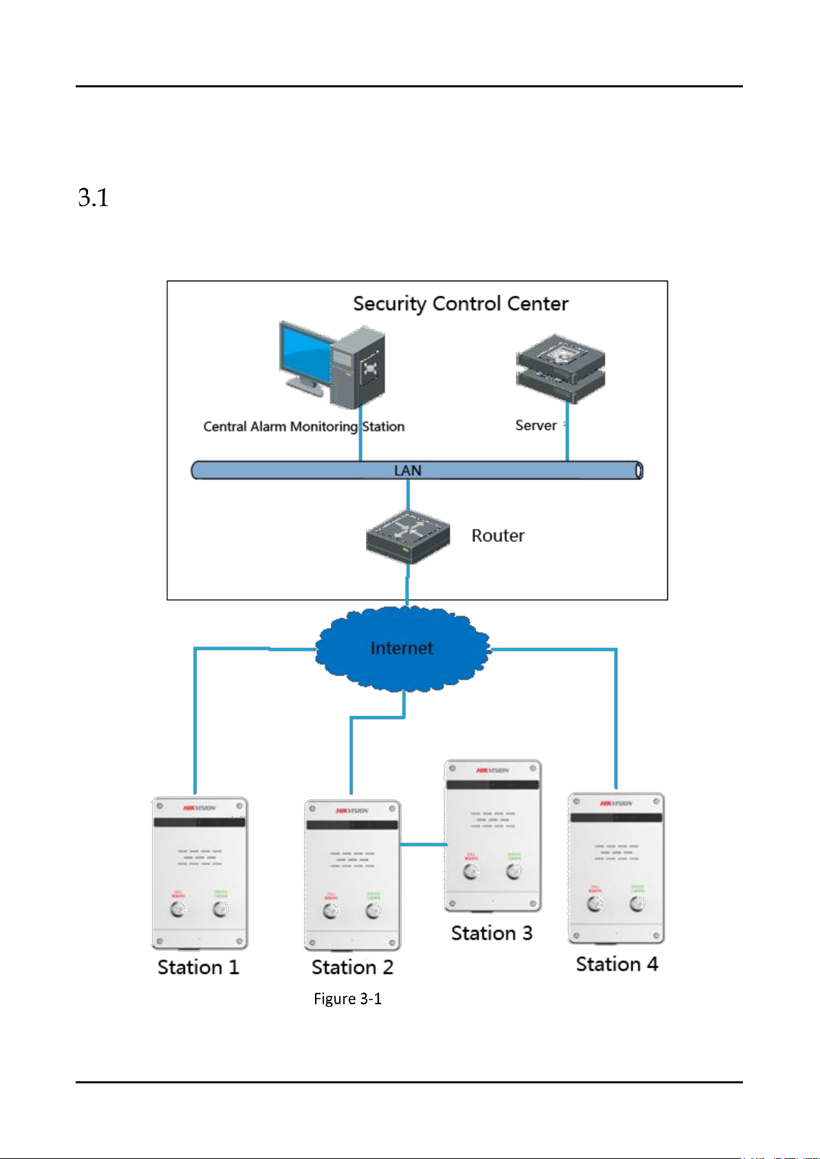
Typical Application
The series of panic alarm station supports cascading communication via network cable wiring. The
typical application of the system is shown in the following picture.
Typical Application
Page 11
Panic Alarm Station with Covert Camera User Manual
5
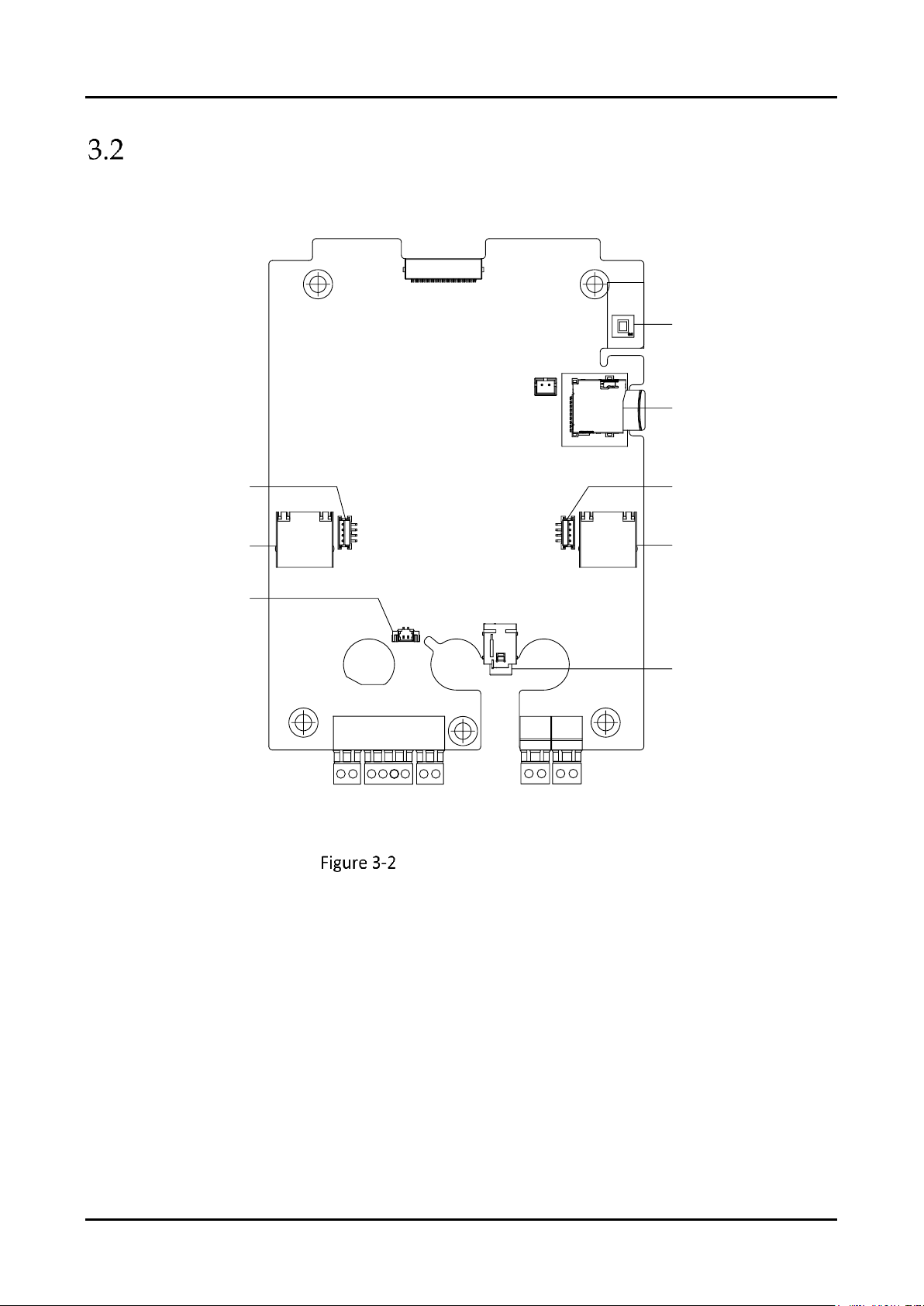
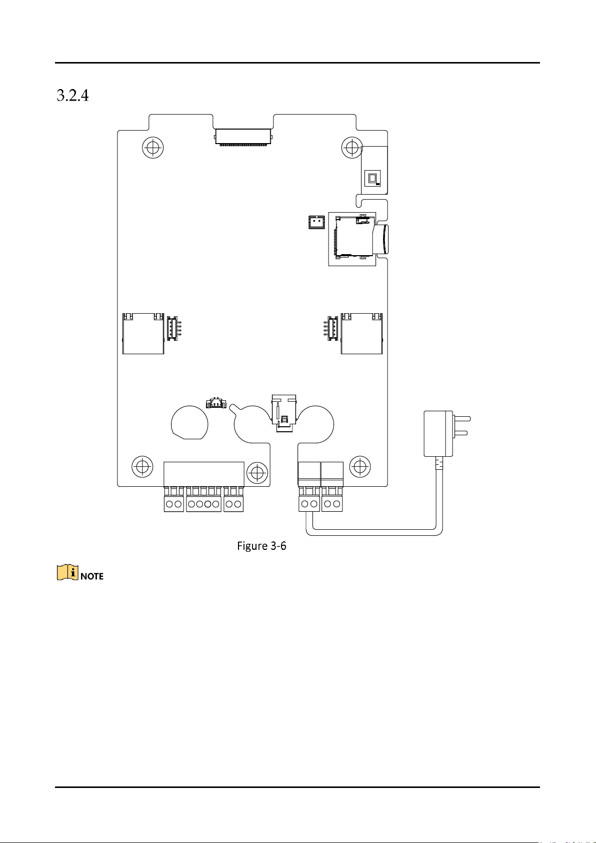
Wiring Description
Take the panic alarm station with help button as an example, the main board description is shown
in Figure 3-2.
Tampering Switch
Micro SD Card Slot
Network In Interface
Panic button Terminal
Help Button Terminal
Audio Output Terminal
Microphone
Network Out Interface
+12V
G
485-
COM
NO/NC
Z1
Z2
G
G
+12V
G
485+
Mainboard of Alarm Station
Page 12
Panic Alarm Station with Covert Camera User Manual
6
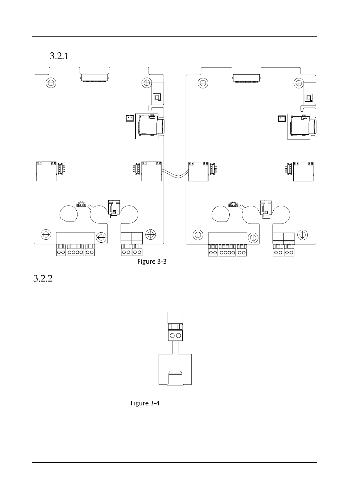
Network Wiring
Network
Out
Interface
Mainboard
Mainboard
Network
In
Interface
Network
Out
Interface
Network
In
Interface
Network Wiring
Alarm Output Wiring
+ -
Alarm Senor
+12V
G
Alarm Output Wiring
Page 13
Panic Alarm Station with Covert Camera User Manual
7
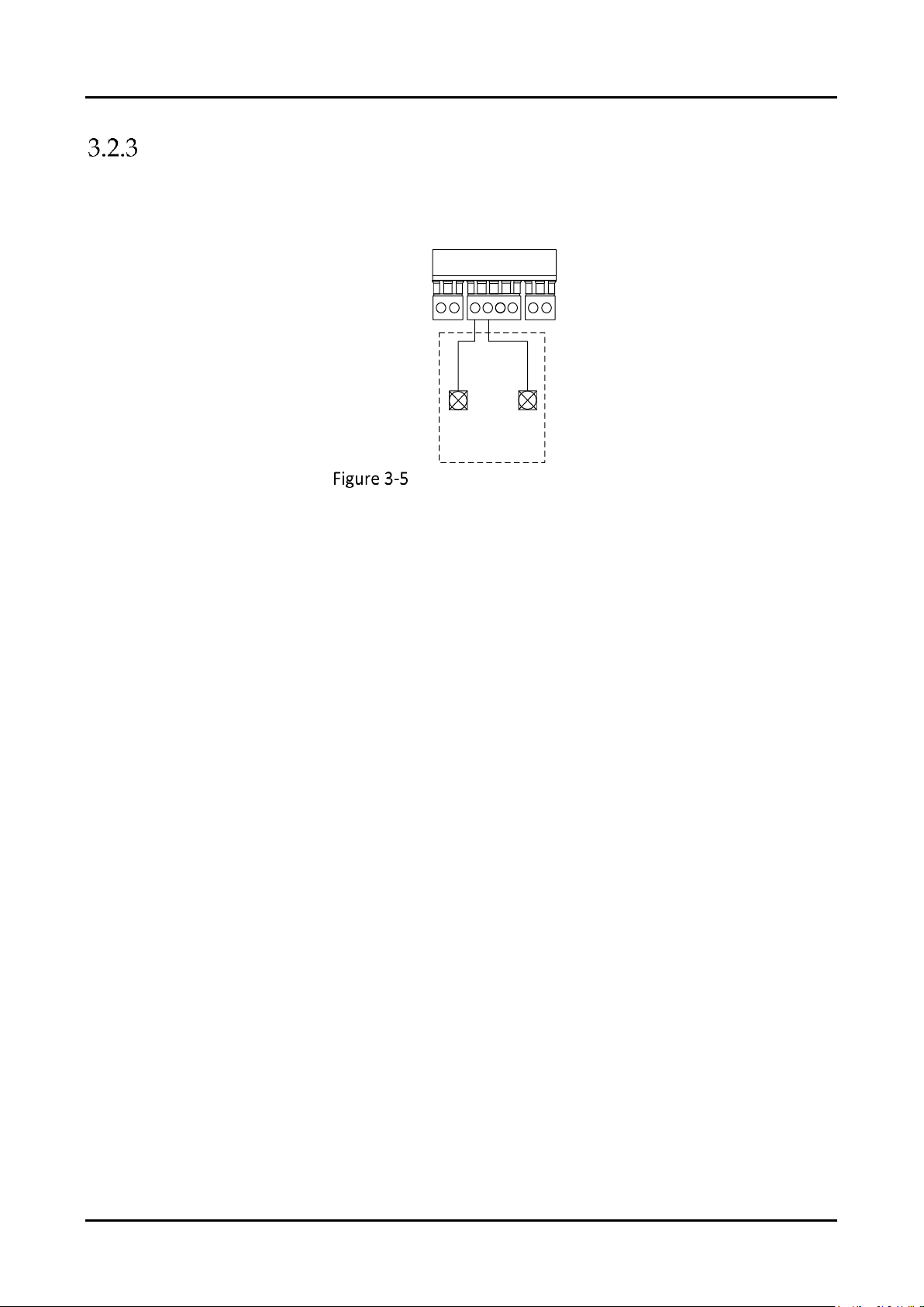
Alarm Input Wiring (Normally Open)
COM
NO/NC
Z1
Z2
G
G
+12V
G
Detector
Normal
Open
NO
C
Alarm Input Wiring (NO)
Page 14
Panic Alarm Station with Covert Camera User Manual
8
Power Supply Wiring
Power interface
Network
Out
Interface
Power Adapter
Mainboard
Network
In
Interface
Power Supply Wiring
The standard of power supply should be 12 VDC/2A.
Page 15
Panic Alarm Station with Covert Camera User Manual
9
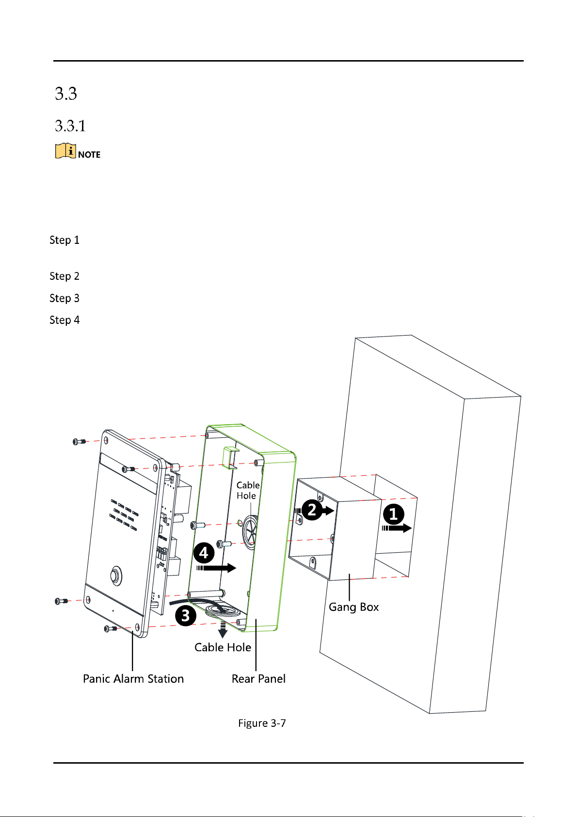
Installation
Installation Description
Please check whether there are all relevant accessories in the package before installation.
The installation of the alarm station requires 86 gang box. (Gang box is optional.)
Make sure the power supply is appropriated (12VDC).
Make sure the device is powered off before installation..
Drill a hole in the wall, and fix the gang box in the wall. The size of the hole should be 76 mm
(width) × 76 mm (length) × 50 mm (depth).
Fix the rear panel of the alarm station to the gang box with two screws (supplied).
Route the cables and complete the wiring. Refer to 3.1 for wiring details.
Secure the panic alarm station to the rear panel with four screws (supplied).
Installation
Page 16

Panic Alarm Station with Covert Camera User Manual
10
Chapter 4 Device Remote Operation
Purpose:
For the first time use of the device, you are required to activate the device and set the activation
password. You can activate the device with SADP Tool, or with iVMS-4200 client software.
The default values of alarm station are as follows.
The default IP address: 192.0.0.65.
The default port No.: 8000.
The default username (administrator): admin.
Activation via SADP Tool
Run the SADP software to search the online devices.
Check the device status from the device list, and select an inactive device.
Create a password and input the password in the password field, and confirm the password.
STRONG PASSWORD RECOMMENDED– We highly recommend you create a strong password of your own choosing
(using a minimum of 8 characters, including upper case letters, lower case letters, numbers, and special characters) in
order to increase the security of your product. And we recommend you reset your password regularly, especially in the
high security system, resetting the password monthly or weekly can better protect your product.
Click OK to save the password.
You can check whether the activation is completed on the popup window. If activation failed,
please make sure that the password meets the requirement and then try again.
Page 17

Panic Alarm Station with Covert Camera User Manual
11
Change the device IP address to the same subnet with your computer by either modifying
the IP address manually or checking the checkbox of Enable DHCP.
Input the password and click the Modify button to activate your IP address modification.
Remote Operation via Client Software
Activation via Client Software
The client software is versatile video management software for multiple kinds of devices.
Get the client software from the supplied disk or the official website, and install the software
according to the prompts. Follow the steps to activate the control panel.
Run the client software and the control panel of the software pops up, as shown in the figure
below.
Click the Device Management icon to enter the Device Management interface, as shown in
the figure below.
Click Add Device Type to enter the adding device type page.
Select Security Control Panel.
Page 18

Panic Alarm Station with Covert Camera User Manual
12
Click Security Control Panel in the Organization list.
Check the device status from the device list, and select an inactive device.
Click the Activate button to pop up the Activation interface.
Create a password and input the password in the password field, and confirm the password.
STRONG PASSWORD RECOMMENDED– We highly recommend you create a strong password of your own choosing
(using a minimum of 8 characters, including upper case letters, lower case letters, numbers, and special characters) in
order to increase the security of your product. And we recommend you reset your password regularly, especially in the
high security system, resetting the password monthly or weekly can better protect your product.
Click OK button to start activation.
Click the Modify Netinfo button to pop up the Network Parameter Modification interface, as
shown in the figure below.
Page 19

Panic Alarm Station with Covert Camera User Manual
13
Change the device IP address to the same subnet with your computer by either modifying
the IP address manually or checking the checkbox of Enable DHCP.
Input the password to activate your IP address modification.
Add a Device
Click the icon on the control panel to enter the Device Management interface and
click the Server tab.
Click Add New Device Type on the Organization list and select Security Control Panel.
Click OK to save the settings, and the added security control panel type is displayed on the
Organization list.
Click Security Control Panel and click Add Device to add the device to the management list of
the software.
Page 20

Panic Alarm Station with Covert Camera User Manual
14
You can add the active online devices in the same local subnet with the client software, or
select the adding mode by IP/Domain Name, by IP segment, by IP Server, or by HiDDNS, and
configure the corresponding settings for the device. Take IP/Domain Name as an example.
Input the required information.
Nickname: Edit a name for the device as you want.
Address: Input the device’s IP address or domain name.
Port: Input the device port number. The default value is 8000.
User Name: Input the device user name.
Password: Input the device password.
Optionally, you can check the checkbox Export to Group to create a group by the device
name. All channels and alarm inputs of the device will be imported to the corresponding
group by default.
Click Add to add the device.
Zone Settings
Click Device Management > Security Control Panel > Remote Configuration > Alarm > Zone
to enter the Zone configuration interface.
In the Alarm Input list, select an alarm input channel and click the icon to enter the zone
settings interface.
Page 21

Panic Alarm Station with Covert Camera User Manual
15
Edit the general information of the zone, including name, detector type, zone type,
sensitivity, audio file etc.
Detector Type: Select the type of the detector.
Zone Type: Select the type of zone in the partition.
Sensitivity: Select the response time of the zone.
Select the linked trigger and others.
Click Copy to to copy all these settings to other zones.
Click Save to save the settings.
Page 22

Panic Alarm Station with Covert Camera User Manual
16
Four zone types in the Zone Parameters: Instant Zone, Fire Alarm Arming Zone, 24 Hour Nonvoiced Zone and Shield Zone.
Instant Zone
Alarm is sent out without any delay once the detector is
triggered.
Fire Alarm Arming
Zone
When the 24-hour armed zone is triggered by fire alarm,
sirens will send out resonant and special sound.
24 Hour Non-voiced
Zone
When the 24-hour armed zone is triggered, it will send
alarm reports to the surveillance center without any audible
warning. The 24 hour silence alarm zone is not affected by
manual or scheduled arming/disarming.
Shield Zone
The alarm will not be triggered.
Panic alarm station has three zones among which two are ordinary zones and one is emergency
zone.
Zone Event Settings
Steps:
Click Control Panel > Event Management > Zone Event to enter the Zone Event
configuration interface.
Select the corresponding zone on the left and then tick necessary items.
(Optional) Click Copy to to tick the necessary items.
Page 23

Panic Alarm Station with Covert Camera User Manual
17
Click Save to save the settings.
The Alarm In is emergent by default.
Alarm Pop-up Window Settings
Purpose:
When the devices are armed, the alarm intercom will pop up once the detectors are triggered.
Enable Pop-up Window Function
When the devices are arming, enable the pop-up window by following the steps bellow.
Steps:
Click Tool > Device Arming Control to enter the device arming control interface.
Click the alarm device to make it in the state of arming.
Pop-up Window Operation
When the window pops up, you can
Page 24

Panic Alarm Station with Covert Camera User Manual
18
click to answer the alarm calling or service consulting;
click to reject the alarm calling or service consulting;
click to hold on the calling or consulting;
click to set volume of audio in and click to set the volume of audio out;
click to capture picture;
click to start videoing and click to stop videoing.
Broadcast Settings
Steps:
Click Tool > Broadcast to enter the broadcast management interface.
Click the corresponding item.
(Optional) Unclick the corresponding item if you want to cancel the broadcast.
Click Save to save the setting.
After the broadcast setting, the client can broadcast to multiple devices.
Page 25

Panic Alarm Station with Covert Camera User Manual
19
Chapter 5 Remote Operation via iVMS-4200
System Information Settings
Purpose:
In this section, you can configure the system parameters (such as time, log, user, security, system
maintenance and so on) for the device.
General Settings
Steps:
Click Remote Configuration > System > General to enter the general parameters
configuration interface.
Page 26

Panic Alarm Station with Covert Camera User Manual
20
Device information
Input the device name and device number.
Click the drop down menu to select whether to overwrite the record files.
Click Save to save the settings.
Timing Settings
Purpose:
Before you start configuring the security control panel, you need to do timing for the device first.
Steps:
Click Remote Configuration > System > Time to enter the time configuration interface.
Page 27

Panic Alarm Station with Covert Camera User Manual
21
Click Synchronization to do timing.
System Maintenance
The device supports system maintenance remotely. Click Remote Configuration > System > System
Maintenance to enter the interface.
Restart the System
Click Reboot to restart the device.
Page 28

Panic Alarm Station with Covert Camera User Manual
22
Restore Default Settings
Click Restore Default Settings to restore the default settings.
Except the IP address and user parameters, all other parameters of the device will be restored to factory default settings.
Restore All the Parameters to Default
Click Restore All to restore all the parameters to factory default settings.
After restoring the parameters to default, the device needs to be restarted.
Import Configuration File
The device supports importing the configuration file. Click Import Configuration File to
import the file.
Export Configuration File
The device supports exporting the configuration file. Click Export Configuration File to export
the file.
Import/Export IPC Configuration File
The device supports importing/exporting the IPC configuration file. Click Import/Export IPC
Configuration File to import/export the file.
Remote Upgrade
The device also supports remote upgrading. You can select the upgrade file including security
control panel upgrading file and alarm keypad upgrading file. Click to select the local
upgrading file and click Upgrade to upgrade the device. The upgrading progress is shown
below.
You need to enter the keypad address for keypad remote upgrade.
After upgrading, the device needs to be restarted.
Log Searching
Click Remote Configuration > System > Log to search and view the logs. Set the search mode,
major type, minor type, start time and end time, and then click Search to search the log.
Page 29

Panic Alarm Station with Covert Camera User Manual
23
User Settings
Purpose:
You can add, edit, or delete the user in this section.
Add an admin User (Only one admin user can be added)
Steps:
Click Remote Configuration > System > User to enter the user configuration interface.
Click to enter the interface of adding a network user.
Page 30

Panic Alarm Station with Covert Camera User Manual
24
Enter the corresponding user information including the user type, user name, password, IP
address, and MAC address.
Select the permission of the user.
Click OK to finish the settings.
Edit a User
Steps:
Click to enter the interface of editing the selected user.
Edit the corresponding user information including the user type, user name, password, IP
address, and MAC address.
Edit the permission of the user.
Click OK to finish the settings.
Page 31

Panic Alarm Station with Covert Camera User Manual
25
Delete a User
Steps:
Select a user needs to be deleted.
Click to delete the user.
Password Management
Click Remote Configuration > System > Password Management to set the maximum password
attempts and lock duration.
Network Settings
Purpose:
You can edit the general network parameters in this section.
General Network Parameters Settings
Steps:
Click Remote Configuration > Network > General to enter the general network configuration
interface.
Page 32

Panic Alarm Station with Covert Camera User Manual
26
Configure the NIC setting.
Click Save to save the above settings.
Network Center Settings
Purpose:
In this section, you can configure the parameters (such as server type, IP address, port NO.,and so
on) of the network center.
Steps:
Click Remote Configuration > Network > Network Center Configuration to enter the
network center configuration interface.
Page 33

Panic Alarm Station with Covert Camera User Manual
27
Click and select a network center. Two centers are selectable.
Click Enable Upload Center.
Click the dropdown menu to select a sever type. Two sever types are available: IP4/IP6 and
domain.
Enter the IP address which is used to communicate with the network alarm receiving center.
Enter the port NO. for communicating with the alarm receiving center.
Click the dropdown menu to select the protocol type.
Enter the username which is applying for displaying in the alarm receiving center.
The length of the username should be 6 characters.
Only numeric (0~9), and letter (A~F&a~f) are valid for this username.
Call Center Settings
Purpose:
You can configure the parameters (such as report uploading time period, center name, phone
number and so on) for each call center in this section.
Steps:
Click Remote Configuration > Network > Call Center Configuration to enter the call center
configuration interface.
Page 34

Panic Alarm Station with Covert Camera User Manual
28
Select a center type (only center 1 is available).
Enter the center name and phone number.
The maximum length of center name is 32 characters.
The phone number should be 31 characters and the input mode is
{NO.}{Dwell Time}{EXT NO.}. For example, in the number of 000088075998FFF8180, the
letter F (which means 2 seconds) represents the dwell time, if the number of the letter F is
N, the dwell time is N*F seconds. The number of F is suggested to be more than 3, which
means the dwell time should be more than 6 seconds.
Enter the dialing times (1~15). The dialing times represents the times that the control panel
trying to communicate the alarm receiving center.
Select the communication protocol.
Select the transmission mode: DTMF5/S and DTMF10/S.
Enter the receiver ID which is the authentication account while doing the communication
with the alarm receiving center.
Click Save to save the settings.
Advanced Network Parameters Settings
Steps:
Click Remote Configuration > Network > Advanced Settings to enter the advanced network
configuration interface.
Page 35

Panic Alarm Station with Covert Camera User Manual
29
Enter the corresponding DNS sever address.
Enter the IP address and port NO. of the control panel.
Click Save to save the settings.
CMS Settings
Purpose:
CMS is used to configure EHome protocol parameters for the device.
Steps:
Click Remote Configuration > Network > CMS to enter the CMS configuration interface.
Page 36

Panic Alarm Station with Covert Camera User Manual
30
Click the dropdown menu to select a sever type. Two sever types are available: IP4/IP6 and
domain.
Enter the IP address which is used to communicate with the service.
Enter the port NO. for communicating with the service. The default port NO. for EHome
protocol is 7660 and for privacy protocol is 10001.
Click the dropdown menu to select the communication network. Four types are available:
Auto, Wired Network Priority, Wired Network and Wireless Network.
Enter the device ID where the CID report comes from.
The length of the device ID should be 6 characters.
Only numeric (0~9), and letter (A ~ F & a ~ f) are valid for this device ID.
Click Save to save the settings.
Sip Settings
Steps:
Page 37

Panic Alarm Station with Covert Camera User Manual
31
Click Remote Configuration > Network >Sip Config to enter the Sip configuration interface.
Check Enable box to enbale the Sip server.
Enter the Sip server parameters including IP address, port No., local No., display name, login
cycle.
The server port No. ranges from 1024 to 65535.
The device ID ranges from 0 to 999999.
The characters of local No. should be 1 to 64.
The login cycle ranges from 1 to 30 (min)
Click Save to save the settings.
Storage Settings
HDD Information `
Steps:
Click Remote Configuration > Storage > General to enter the HDD Settings interface. You
can view the capacity, free space, status, type and property of the disk.
Page 38

Panic Alarm Station with Covert Camera User Manual
32
If the status of the HDD is Uninitialized, check the corresponding checkbox to select the disk
and click to start initializing the disk. When the initialization completed, the status
of disk will become Normal.
Click Save to save the settings.
This function is available only if the device is connected with HDD.
File Query
Steps:
Click Remote Configuration > Storage > File to enter the file query interface.
Page 39

Panic Alarm Station with Covert Camera User Manual
33
Enter the search criteria including camera name, property, start time and end time.
Click Search to get the file list.
Alarm Settings
Zone Settings
Steps:
Click Remote Configuration > Alarm > Zone to enter the Zone configuration interface.
Page 40

Panic Alarm Station with Covert Camera User Manual
34
In the Alarm Input list, select an alarm input channel and click the icon to enter the zone
setting interface.
Edit the general information of the Zone, including name, detector type, zone type,
sensitivity and so on.
Detector Type: Select the type of the detector.
Zone Type: Select the type of Zone in the partition.
Sensitivity: Select the response time of the Zone.
Select the linked trigger and others.
Click Copy to to copy all these settings to other Zones.
Click Save to save the settings.
Page 41

Panic Alarm Station with Covert Camera User Manual
35
Trigger Settings
Steps:
Click Remote Configuration > Alarm > Trigger to enter the trigger configuration interface.
In the Alarm Output list, select the alarm output channel and click the icon to enter
trigger parameters setting interface.
Edit the general information of the trigger, including name, output delay and so on.
Output Delay (0~5999s): Configure the alarm output time after the alarm being triggered.
Click Copy to to copy all these settings to other Zones.
Click Save to save the settings.
Calling Waiting Settings
Steps:
Click Remote Configuration > Alarm > Waiting to enter the trigger configuration interface.
Page 42

Panic Alarm Station with Covert Camera User Manual
36
Enter the Max. ring duration (40s to 80s)for reporting alarm to the center.
Enter the waiting time (10s to 60s) for the center to answer the call.
Click Save to save the settings.
Alarm Lamp Settings
Steps:
Click Remote Configuration > Alarm > Alarm Lamp Flicking to enter the trigger configuration
interface.
Check Enable Alarm Lamp Flicking box.
Enter the alarm lamp flashing duration (s).
Enter the time interval for each flashing(s).
Page 43

Panic Alarm Station with Covert Camera User Manual
37
Click Save to save the settings.
If the duration is 180s and the time interval is 3600s, the alarm lamp flashes 3 minutes each hour.
Voice Prompt Settings
Steps:
Click Remote Configuration > Alarm > Voice Promptto enter the trigger configuration
interface.
Check Enable Alarm Lamp Flicking box.
Select Female/Male voice for center busy file, refuse, and voice talking prompt.
Select the ring tone.
Slick Save to save the settings.
Image Settings
Video& Audio Settings
Steps:
Click Remote Configuration > Image > Video & Audio to enter the video/audio configuration
interface.
Page 44

Panic Alarm Station with Covert Camera User Manual
38
Select a camera needs to be configured.
Edit the general video parameters.
Scream Type: The main stream is usually for recording and live viewing with good bandwidth,
and the sub-stream can be used for live viewing when the bandwidth is limited.
Video Type: Select the stream type to video stream, or video & audio composite stream.
Bitrate Type: Select the bitrate type to constant or variable.
Resolution: Select the resolution of the video output.
Frame Rate: The frame rate is to describe the frequency at which the video stream is updated
and it is measured by frames per second (fps). A higher frame rate is advantageous when
there is movement in the video stream, as it maintains image quality throughout.
I Frame Interval: Set the I-Frame interval from 1 to 400.
Click Copy to to copy all these settings to other Zones.
Click Save to save the settings.
OSD Settings
Steps:
Click Remote Configuration > Image > Video Display to enter the OSD Settings interface.
Page 45

Panic Alarm Station with Covert Camera User Manual
39
Check the corresponding checkbox to select the display of camera name, date or week if
required.
Edit the camera name in the text field of Camera Name.
Select from the drop-down list to set the time format, date format and display mode.
Check the checkbox in front of textbox to enable the on-screen display.
Input the characters in the textbox.
Use the mouse to click and drag the red text frame in the live view window to adjust
the text overlay position.
Click Save to save the settings.
Image Settings
Steps:
Click Remote Configuration > Image > Image Settings to enter the image settings interface.
Page 46

Panic Alarm Station with Covert Camera User Manual
40
Drag the to adjust the brightness, contrast, saturation of the image.
You can also click Default Value to restore the default values.
Event Settings
Schedule Settings
Click Remote Configuration > Events > Schedule to enter the record schedule configuration
interface.
Page 47

Panic Alarm Station with Covert Camera User Manual
41
Record Schedule Settings
Steps:
Select the camera needs to be configured.
Check the checkbox of Local Recording to enable the device local recording. You can also
check ANR checkbox to enable the device continuing recording even if the network is off.
Select from the drop-down list to set the recording type including Main Stream and Sub
Stream.
Click the icon to set the record schedule.
Click Edit to enter the Templates Management interface. Select the template to be set and
you can edit the template name.
Set the time schedule for the selected template.
When the cursor turns to , you can edit the schedule time bar.
Page 48

Panic Alarm Station with Covert Camera User Manual
42
When the cursor turns to , you can move the selected time bar you just edited.
When the cursor turns to , you can lengthen or shorten the selected time bar.
Optionally, you can select the schedule time bar,
And then click the icon to delete the selected time bar,
Or click the icon to delete all the time bars,
Or click the icon to copy the time bar settings to the other dates.
Click Save to save the template, or click cancel to exit the interface.
Click Advanced Settings button to set the pre-record time, post record time, video expired
time, redundant record and audio recording.
Click Copy to to copy all these settings to other Zones.
Click Save to save the settings.
Capture Schedule Settings
Check the checkbox of Capture Settings to enable the device local capturing.
Click the icon to set the capture schedule. For details, refer to Steps 5, 6, 7
in Record Schedule Settings.
Click Copy to to copy all these settings to other Zones.
Click Save to save the settings.
Camera Parameter Settings
Video Parameter Settings
Steps:
Click Remote Configuration > Camera Parameter > Video Parameter to enter the interface.
Select the monitoring point.
Click Save to save the settings.
Page 49

Panic Alarm Station with Covert Camera User Manual
43
WDR Settings
Steps:
Click Remote Configuration > Camera Parameter > WDR to enter the interface.
Select the monitoring point and then choose whether to open.
Set the WDR level.
Click Save to save the settings.
Audio Detection
Audio detection is used to whether the voice function of the alarm station is complete and
whether the network is stable.
Steps:
Click the icon on the control panel to enter the live viewing.
Right click and click Start AudioDetection.
Use the microphone to detect the audio function.
Click Stop Audio Detection.
Page 50

Panic Alarm Station with Covert Camera User Manual
44
 Loading...