

Page 1
Installation Guide
DS-8104AH(L)I-S Series DVR
Installation Guide - DS-8104AH(L)I-S Series DVR 1
Verify Contents
Verify that the package contents are correct by checking the
items against the packing list.
Note: Please contact your dealer for damaged or missing
items.
DVR Pre-Installation
The DS-8104AH(L)I-S Series DVRs are highly advanced
surveillance equipment that should be installed with care.
Please take into consideration the following precautionary
steps before installation of the DVR.
1. Keep all liquids away from the DVR.
2. Install the DVR in a well-ventilated and dust-free area.
3. Ensure environmental conditions meet factory
specifications.
4. Install a manufacturer recommended HDD.
DVR Installation
During the installation of the DVR:
1. Use brackets for rack mounting.
2. Ensure there is ample room for audio and video cables.
3. When installing cables, ensure that the bend radius of the
cables are no less than five times than it’s’ diameter.
4. Connect both the alarm and RS-485 cable.
5. Allow at least 2cm (~0.75in) of space between racks
mounted devices.
6. Ensure the DVR is grounded.
7. Environmental temperature should be within the range of
-10ºC ~ 55ºC, 14ºF ~ 131ºF.
8. Environmental humidity should be within the range of
10% ~ 90%.
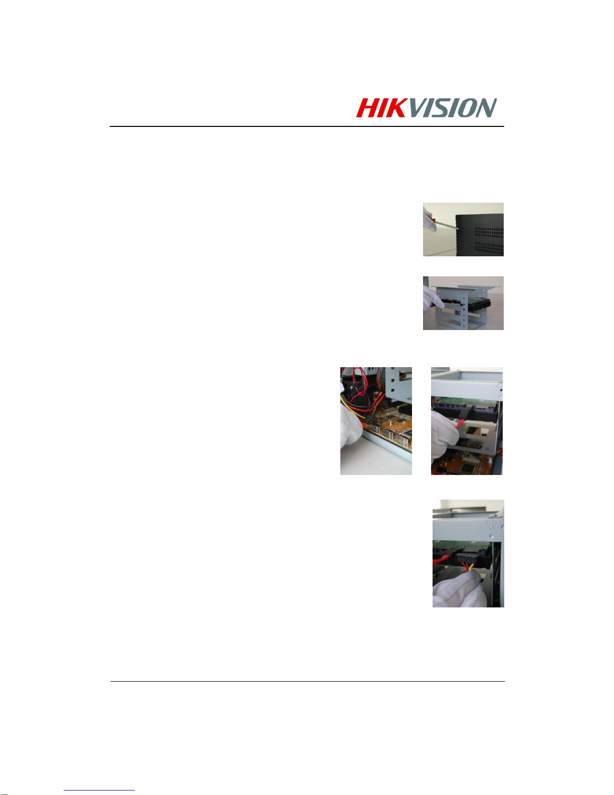
Hard Disk Installation
Before installing a hard disk drive (HDD), please make sure
the power is disconnected from the DVR. A factory
recommended HDD should be used for this installation.
Tools Required: Phillips screwdriver.
To install a HDD on your DVR:
1. Remove the lid of the DVR by unfastening the screws
on the back.
2. Take off the chassis and install the HDD on the chassis
3. Connect the HDD to the motherboard of the DVR with
the included data cable.
4. Connect the power cable to the HDD.
5. Re-install the lid of the DVR and fasten screws.
Page 2

2 Installation Guide - DS-8104AH(L)I-S Series DVR
Rear Panel Diagram
No.
Item
Description
1
VIDEO
OUT
BNC connector for video output. If VGA is connected, the interface will not function. If
VGA is not connected, the interface is used as the main video output with local video
display and menu operations.
AUDIO
OUT
BNC connector for audio output. This connector is synchronized with VIDEO OUT.
2
VIDEO IN
BNC connectors for analog video input.
3
AUDIO IN
BNC connectors for analog audio input.
4
VIDEO
OUT
RCA connector for audio output. Can be connected to analog recorder.
AUDIO
OUT
RCA connector for audio output. This connector is synchronized with VIDEO OUT and
can be connected to analog recorder.
5
VGA
VGA output. Display local video output and menu.
6
RS-232
Interface
RJ45 connector for RS232 devices.
RS-485
Interface
RJ45 connector for RS-485 devices.
7
UTP
Interface
Connector for LAN (Local Area Network).
8
USB
Interface
Connector for USB devices.
9
ALARM IN
5-ch connectors for alarm input. 1-ch has DC+12V/1A power supply for sensor.
Page 3

Installation Guide - DS-8104AH(L)I-S Series DVR 3
ALARM
OUT
2-ch connectors for alarm output.
10
LINE IN
BNC connector for audio input
11
DC OUT
DC+12V/1A power output for camera.
12
POWER
AC 100~240V
13
GROUND
Ground(needs to be connected when DVR startup)
Page 4

4 Installation Guide - DS-8104AH(L)I-S Series DVR
Peripheral Connections
Connecting to Alarm Input / Output Device
The alarm input/output interface of the DVR is shown below:
The alarm input is an open/close relay. If the input is not an
open/closed relay, follow the connection diagram below:
To connect to an AC/DC load, use the following diagram:
For DC load, JP4 can be used within the limit of 12V/1A
safely. If the interface is connected to an AC load, JP4 should
be left open. Use an external relay for safety (as shown in the
figure above).
There are 4 jumpers (JP4, JP5, JP6, and JP7) on the
motherboard, each corresponding with one alarm output. By
default, jumpers are connected. To connect an AC load,
jumpers should be removed.
Note: An external relay is needed to prevent electric shock
when connecting to an AC load.
Alarm Connection
To connect alarm devices to the DVR:
1. Disconnect pluggable block from the ALAM IN /ALARM
OUT terminal block.
2. Unfasten stop screws from the pluggable block, insert
signal cables into slots and fasten stop screws. Ensure
signal cables are in tight.
3. Connect pluggable block back into terminal block.
RS-485 Connection
To connect RS-485 of PTZ to the DVR:
1. Disconnect pluggable block from the RS-485 terminal
block.
2. Unfasten stop screws from the pluggable block, insert
signal cables into slots and fasten stop screws. Ensure
signal cables are in tight.
3. Connect pluggable block back into terminal block.
Page 5

Installation Guide - DS-8104AH(L)I-S Series DVR 5
4. Connect the other side of cable back to RJ45 of RS-485
interface.
Note: The PTZ control should be connected with the 1
st
and
2nd pin of RS-485 interface on the rear panel of DVR.
HDD Storage Calculation
Chart
The following chart shows an estimation of storage space
used based on recording at one channel for an hour at a fixed
bit rate.
Bit Rate
Storage Used
96K
42M
128K
56M
160K
70M
192K
83M
224K
98M
256K
112M
320K
140M
384K
168M
448K
196M
512K
225M
640K
281M
768K
337M
896K
393M
1024K
450M
1280K
562M
1536K
675M
1792K
787M
2048K
900M
Note: Please note that supplied values for storage space
used is just for reference. Storage space used is estimated by
formulas and may have some deviation from actual value.
 Loading...