

HIKVISION DS-8004HDI-S, DS-8008HCI-S, DS-8008HDI-S, DS-8016HDI-S, DS-8004HFI-S User Manual
...Page 1

1
DS-8000 Series Net DVR
User Manual
V2.1
Thank you for purchasing our Embedded Net DVR. This manual is applicable to DS-8000 series
Net DVRs. Please go through this User Manual before operating so as to use the DVR in the
correct and safe way.
The content of this manual is subject to change without notice.
Page 2

2
Index
Chapter1 Product Introduction .................................................................................................. 8
1.1 Summary ...................................................................................................................... 8
1.2 Model Description ........................................................................................................ 8
1.3 Features ........................................................................................................................ 9
1.4 T ypical Application .................................................................................................... 11
Chapter2 Installation ............................................................................................................... 12
2.1 Check DVR and its Accessories ................................................................................. 12
2.2 HDD Installation ........................................................................................................ 12
2.3 DS-8000HCI-S Rear Panel Connection ..................................................................... 17
2.4 DS-8000HDI-S Rear Panel Connection ..................................................................... 19
2.5 DS-8000HFI-S Rear Panel Connection ...................................................................... 20
2.6 DS-8000HSI-S Rear Panel Connection ...................................................................... 22
2.7 DS-8000HTI-S Rear Panel Connection ..................................................................... 24
2.8 DS-8000AH(F)(L)I-S Series Rear Panel Connection ................................................ 26
2.9 External Alarm In/Out Connection ............................................................................ 28
2.10 Power On.................................................................................................................... 30
Chapter3 Operational Instructions .......................................................................................... 31
3.1 DVR Front Panel ........................................................................................................ 31
3.2 IR control ................................................................................................................... 37
3.3 OSD Menu Description .............................................................................................. 39
3.3.1 Main Menu Items ............................................................................................... 39
3.3.2 Navigating Menus in DS-8000 series DVR ....................................................... 40
3.3.3 Menu Operation ................................................................................................. 43
3.4 Character Input ........................................................................................................... 45
Chapter4 Basic Operation Guide ............................................................................................ 46
4.1 Power on .................................................................................................................... 46
4.2 Live V iew ................................................................................................................... 47
4.3 Login .......................................................................................................................... 50
4.4 PTZ Control ............................................................................................................... 51
4.5 Manual Record ........................................................................................................... 53
4.6 Playback ..................................................................................................................... 55
4.7 Backup Recorded Files .............................................................................................. 60
4.8 Powering Down the DVR .......................................................................................... 65
Chapter5 Main and Spot Output ............................................................................................. 67
5.1 Main and Spot Output ................................................................................................ 67
5.2 Main and Spot Output Live View ............................................................................... 68
5.3 Main and Spot Output Playback ................................................................................. 70
5.4 Main and Spot Output to Control PTZ ....................................................................... 70
Chapter6 Advanced Operation Guide ..................................................................................... 72
6.1 User Management ...................................................................................................... 73
6.1.1 Add Users .......................................................................................................... 74
Page 3

3
6.1.2 Delete User ........................................................................................................ 75
6.1.3 Password Modification ...................................................................................... 76
6.1.4 User Rights ........................................................................................................ 77
6.2 Device ID ................................................................................................................... 79
6.3 Video Standard and VGA Setup ................................................................................ 80
6.4 Date and Time Setup .................................................................................................. 81
6.4.1 Daylight Saving Time Setup .............................................................................. 83
6.5 Image Setup ................................................................................................................ 84
6.5.1 Camera Name Setup .......................................................................................... 84
6.5.2 Video Parameter Setup ....................................................................................... 85
6.6 Mask Area Setup (Privacy Mask) ............................................................................... 87
6.7 V iew Tampering Alarm .............................................................................................. 89
6.8 V ideo Loss Alarm ....................................................................................................... 91
6.9 Motion Detection Alarm ............................................................................................ 92
6.10 Live V iew Setup ......................................................................................................... 96
6.11 Recording Setup ......................................................................................................... 97
6.12 Alarm I/O Setup ....................................................................................................... 102
6.13 Network Setup .......................................................................................................... 105
6.13.1 Network Settings ........................................................................................... 106
6.13.2 DHCP Function ........................................................................................... 108
6.13.3 PPPoE Function ........................................................................................... 109
6.13.4 IP Server Solution for DHCP ....................................................................... 110
6.14 PTZ Setup ................................................................................................................ 111
6.14.1 PTZ Connection ........................................................................................... 111
6.14.2 PTZ Settings ................................................................................................ 111
6.14.3 PTZ Control ................................................................................................. 113
6.14.4 Preset Setup ................................................................................................. 113
6.14.5 Sequence Setup ............................................................................................ 115
6.14.6 Cruise (Pattern) Setup: ................................................................................. 116
6.15 RS232 Setup ............................................................................................................. 117
6.15.1 Console Mode .............................................................................................. 117
6.15.2 Transparent Channel Mode .......................................................................... 117
6.15.3 PPP Mode .................................................................................................... 117
6.16 Exceptions Setup ...................................................................................................... 122
Chapter7 Utilities .................................................................................................................. 124
7.1 Restore Parameters ................................................................................................... 125
7.2 Hard Disk Management ........................................................................................... 125
7.3 Clear Alarm Out ....................................................................................................... 126
7.4 Reboot ...................................................................................................................... 126
7.5 Power Off ................................................................................................................. 126
7.6 View Log .................................................................................................................. 126
7.7 System Information .................................................................................................. 129
Chapter8 Firmware Upgrade ................................................................................................ 130
8.1 Upgrade from USB Flash ......................................................................................... 130
Page 4

4
8.2 Upgrade from CD ..................................................................................................... 130
8.3 Upgrade from FTP Server ........................................................................................ 131
8.3.1 FTP Server Setup ............................................................................................. 131
8.3.2 Use DVR FTP Upgrade Function .................................................................... 133
8.3.3 Use RS-232 Serial Command .......................................................................... 133
8.4 Use Client Software to Upgrade ............................................................................... 136
Appendix A Mouse Control Function ....................................................................................... 137
Appendix B HDD Capacity Calculation ................................................................................... 139
Appendix C DVR Connector Definition ................................................................................... 140
Appendix D Specifications ........................................................................................................ 146
Appendix E Quick Search ......................................................................................................... 155
Appendix F Troubleshooting .................................................................................................... 157
Appendix G Product Service ..................................................................................................... 159
Appendix H Customer Information Card .................................................................................. 160
Page 5

5
Safety Precautions
Caution:
To reduce the risk of electric shock, please do not remove the cover.
There are no user-serviceable parts inside, please contact us directly for repairing.
Important Safeguards:
1. Go through these instructions.
2. Keep these instructions.
3. Heed all warnings.
4. Follow all instructions.
5. Do not use this apparatus near water.
6. Clean only with a dry cloth.
7. Do not block any ventilation openings. Install in accordance with the manufacturer's
instructions.
8. Do not install near any heat sources such as radiators, heat registers, stoves, or other
apparatus (including amplifiers) that produce heat.
9. Do not defeat the safety purpose of the polarized or grounding-type plug. A polarized plug
has two blades with one wider than the other. A grounding-type plug has two blades and a
third grounding prong. The wide bl a de or third prong is provided for your safety. If the
provided plug does not fit into the outlet, consult an electr ician for replacement of the
obsolete outlet.
10. Protect the power cord from being walked on or pinched particularly at plugs, convenience
receptacles, and the point where they exit from the apparatus.
11. Only use attachments/accessories specified by the manufacturer.
12. Use of a cart, stand, or table is typical for temporary installations to test and demonstrate
products. Use extreme caution to ensure that the product is not subjected to shock or vibration.
When a cart is used, use caution when moving the cart/apparatus combination to avoid injury
from tip-over. Permanent installation requires a solid mounting surface for equipment with no
Page 6

6
movement or vibration.
13. Unplug this unit during lightning storms or when unused for long periods of time.
14. Refer all servicing to qualified service personnel. Servicing is required when the apparatus
has been damaged in any way, such as power-supply cord or plug is damaged, liquid has been
spilled or objects have fallen into the apparatus, the apparatus has been exposed to rain or
moisture, does not operate normally, or has been dropped.
15. Moving - Disconnect the power before moving the unit. The unit should be moved with care.
Even moderate force or shock may result in dam age to the unit and the hard disk drives.
16. Power Sources - This unit should be operated only from the type of power source indicated
on the marking label. If you are not sure of the type of power supply you plan to use, co ns ul t
your appliance dealer or local power company.
17. Overloading - Do not overload outlets and extension cords as this can result in a risk of fire or
electric shock.
18. Object and Liquid Entry - Never push objects of any kind into this unit through openings, as
they may touch dangerous voltage points or short out parts that could result in a fire or
electric shock. Never spill liqui d of any kind on the unit.
19. Replacement Parts - When replacement parts are required, be sure the service technician has
used replacement parts specified by the manufacturer or have the same characteristics as the
original part. Unauthorize d subs titutions may result in fire, electric shock, or other hazards.
20. Coax Grounding - If an outside cable system is connected to the unit, be sure the cable system
is grounded. U.S.A. models only--Section 810 of the National Electrical Code, ANSI/NFPA
No.70-1981, get information from professional electrician to proper gr ou nding of the mount
and supporting structure, grounding of the coax to a discharge unit, size of grounding
conductors, location of discharge unit, connection to grounding electrodes, and requirements
for the grounding electrode.
21. To reduce the risk of fire or electric shock, this apparatus should not be exposed to rain or
moisture and objects filled with liquids, such as vases, should not be p lace d on th is a pparatus.
22. Danger of explosion if battery is incorrectly replaced. Replace only with the same or
equivalent type. Dispose of the replaced battery in an environmentally friendly way.
Page 7

7
Cleaning:
You can clean the unit with a moist lint-free cloth or chamois leather cloth.
Warning:
This device is intended for use in public areas only. Surreptitious recording of oral
communications may be prohibite d by local law.
Unpacking:
Check the package for visible damage. If any items appear to have been damaged in shipment,
notify the shipping company. Unpack carefully. This is electronic equipment and should be
handled with care to prevent damage to the unit. Do not attempt to use the unit if any components
are damaged. If any items are missing, notify the dealer.
The shipping carton is the safest container in which to transport the unit. Save it and all
packing materials for future use. If the unit must be returned, use the original packing materials.
Packaging contents:
The package should contain the following items:
1. Digital Video Recor der
2. Accessories box
Page 8
8
Chapter1 Product Introduction
1.1 Summary
DS-8000 series Network Digital video Recorder is an excellent digital surveillance product adopts
embedded MCU (Microprocessor Control Unit) and an embedded Real-Time Operating System
(RTOS), along with the most advanced technology in the Information technology Industry such as
video and audio encoding/decoding, hard disk recording and TCP/IP transmission. The firmware
is burned into the flash, making it more stable and reliable than software programs running from a
standard disk drive.
DS-8000 series combines the advantages of Digital Video Recorder (DVR) and Digital Video
Server (DVS). It is widely applied as a stand-alone unit or a part of a powerful surveillance
system.
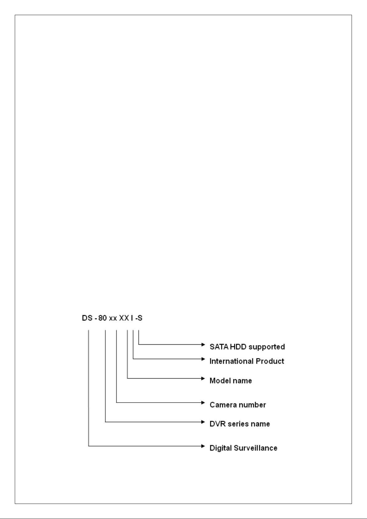
1.2 Model Description
Page 9

9
Note: This model name includes all the DS-8000 series, a real model name is just part of it.
1.3 Features
Compression:
• Support up to 16 video channels (NTSC/PAL). Each channel is independent with H.264
hardware compression.
• Support both variable bit rate and frame rate
• Support up to 16 channels audio input channels. Each channel is independent with
OggVorbis at a bit rate of 16Kbps
• Compressed video and audio are synchronous. Either composited stream (video and
audio) or video-only can be selected.
• Support 4CIF, DCIF, 2 CIF, CIF and QCIF resolution.
• Support multi-area motion detection
• Support OSD and changeable OSD position
Local functions:
Recording:
• Support multiple recording types, including schedule recording, manual recording,
motion detection recording, alarm recording, motion & alarm and motion | alarm
recording, etc.
• Support up to 8 HDDs. Each HDD can support 2000GB maximum.
• Support FAT32 file system
• Support NAS Recording.
• Support Event Recording Para. Setup.
• Support HDD S.M.A.R.T technology
• Support continuous (overwrite) and linear (stop when full) record modes
• Support backup recorded files and video/audio clips with USB memory stick (thumb
drive), USB HDD, USB CD-R/W, USB DVD-R/W SATA HDD or SATA
CD/DVD-R/W.
Page 10

10
Preview and playback:
• Support BNC analog monitor and VGA output for main output
• Support spot video and spot audio output (except DS-8004HCI-S, DS-8000HSI-S Series
and DS-8000AH(F)(L)I-S Series)
• Support user-defined preview layout
• Support Privacy Mask
• Support view tampering alert.
• Support video signal loss alert.
• Support 2-ch synchronous playback (except DS-8008HCI-S, DS-8016HCI-S &
DS-8000HSI-S series).
• Support play forward, backward, pause, frame-by-frame, etc
• Support play back by files or by time/date
• Displays local record status
PTZ:
• Support multiple PTZ protocols
• Support preset, sequence and cruise
Alarms:
• Support exception alarm, motion detection alarm, external alarm, etc
Miscellaneous:
• Support IR Remote control
• Support RS-485 keyboard (except DS-8000AH(F)(L)I-S Series)
• Support multi-level user management
• Support Mouse Operation Menu.
• Support multiple upgrade modes, including FTP, USB and CD.
Network:
• Support Advanced Network Function: NTP, DDNS and E-mail.
• Support TCP, UDP, RTP, Multicast for network viewing
• Support PPPoE
Page 11
11
• Support remote parameters setup
• Alarm information can be sent to remote center
• Network control PTZ
• Network video/audio recording
• Network download and playback recorded files from the DVR
• Remote upgrading DVR firmware
• RS-232 supports transparent channel function so that the remote PC can control serial
devices through DVR.
• Support voice talking (except DS-8000HSI-S Series)
• Support IE preview and configuration
• Support SADP protocol that enables modification of IP address, mask and port via
SADP Client.
• Support remote log query.
Development support:
• Provide network SDK (Software Development Kit)
• Provide client demo source code
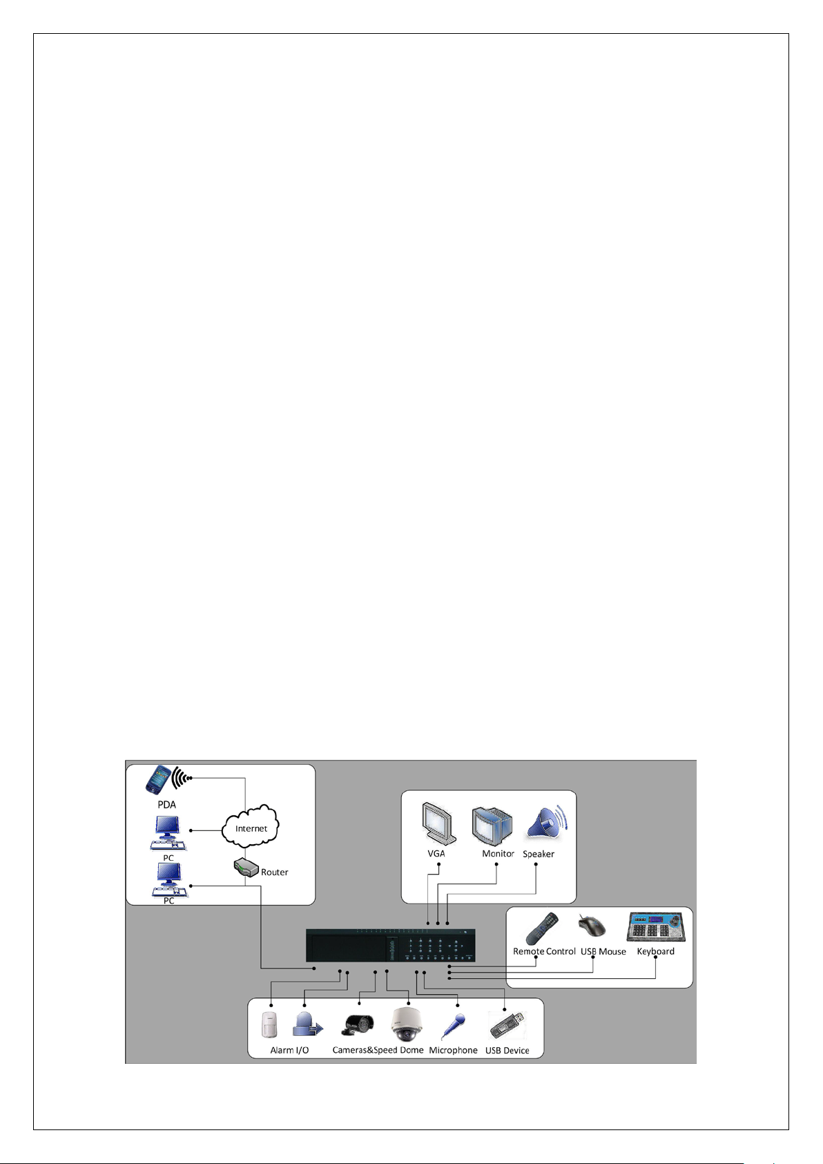
1.4 T ypical Application
Take DS-8000HFI-S for example.
Page 12

12
Chapter2 Installation
2.1 Check DVR and its Accessories
Please follow the packing list in the packing box and care fully check the contents of the shipping
container.
2.2 HDD Installation
Caution:
A factory recommended HDD should be used for this device.
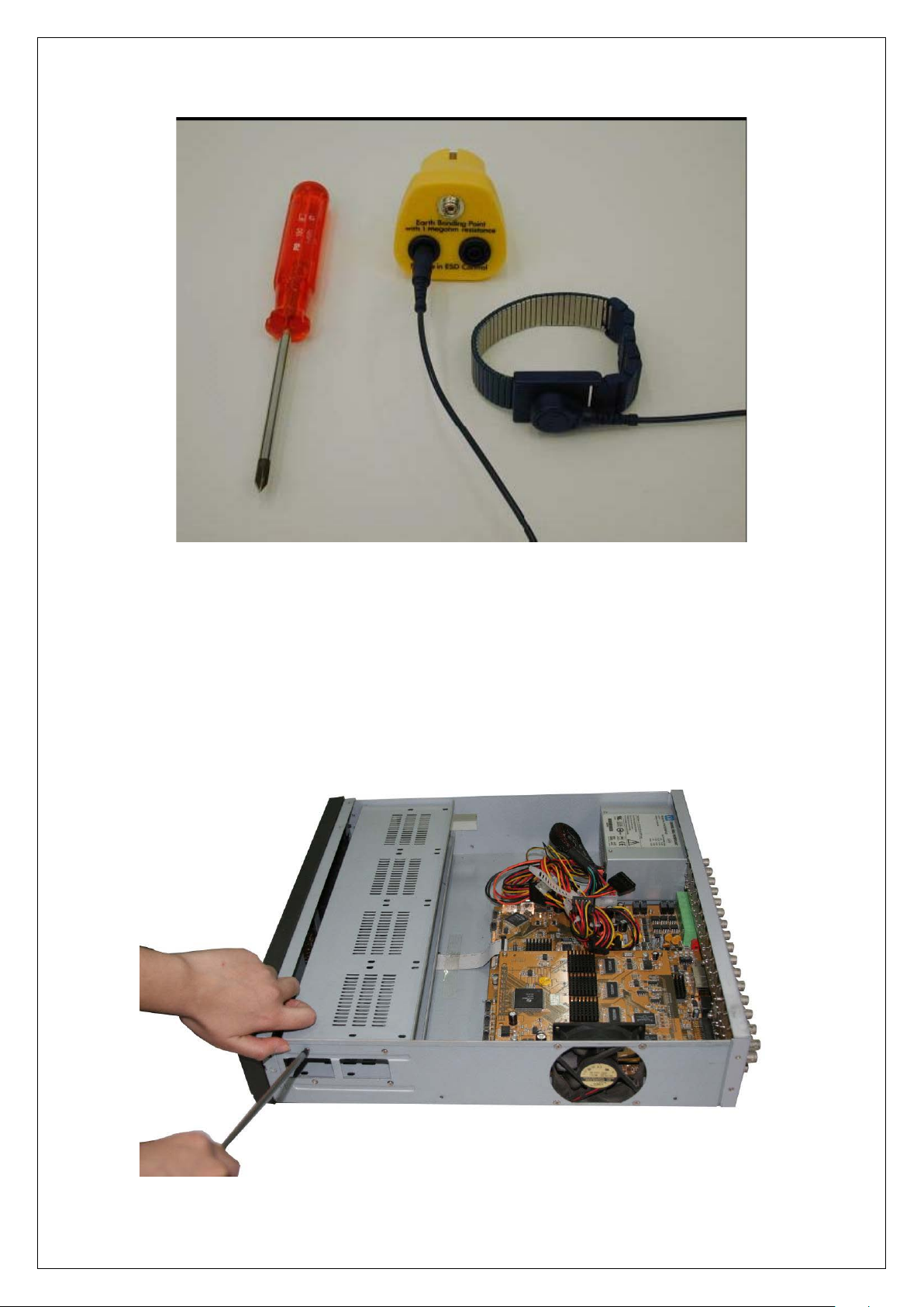
When working with electrostatic sensitive devices such as a hard disk or the DVR unit, make sure
If any of the items is missing, please contact your dealer.
you use a static-free workstation. Any electrostatic energy coming in contact with the hard disk or
DVR main board can damage it permanently.
The DVR is without HDD when leaving factory. Based on the record schedule, you can calculate
the total capacity you need (refer to Appendix A). Please ask the specialist to disassembly the
DVR and install HDD.
Installing the hard disks must be performed by qualified personnel. Unauthorized installation of
hard disks may result in permanent dam age of the disk and the rec or d er , and is performed at your
own risk.
Installing SATA HDD
1. Before installation of the HDD, switch the recorder off and unplug the power cable.
2. Place the recorder on a flat table, and make sure you take proper ESD precautions. Wear an
ESD bracelet at all times. A Philips screwdriver is required to disassemble and reassemble the
unit.
Page 13
13
3. Remove the metal top cover by removing two screws from the rear of the cover, slide the cover
towards the rear and lift it from the unit.
4. Remove the metal hard drive brackets (remove one screw from the top of the mounting plate, lift
the rear of the plate and slide backwards). To remove the bottom plate, remove the mounting
screws that are inserted from the outside of the uni t (one on each side). Make sure that the hard
disk bracket does not come into contact with the PCB, as this could cause damage.
Page 14
14
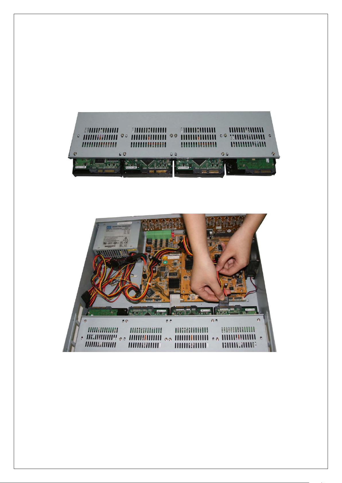
5. Place the hard disks you wish to install on the flat table with the mounting side facing up.
6. Place the metal hard disk bracket on top of the hard disks, and fasten eac h har d disk with 4
screws to the bracket.
7. Reinstall the bracket and then connect the power and data cables to the HDD and main board.
Page 15
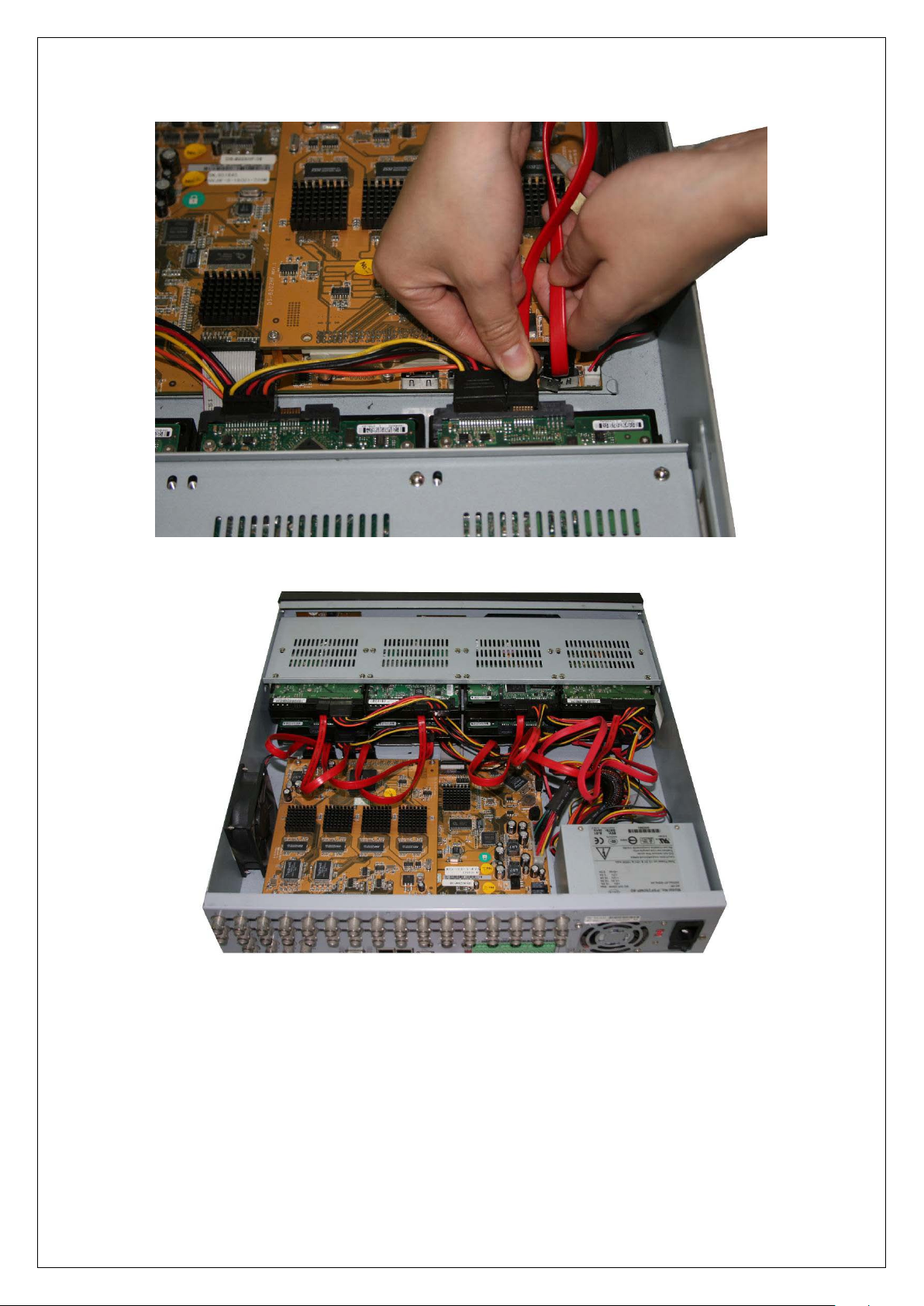
15
8. Check all connections, and reinstall the metal cover on the DVR.
9. Connect the power cable and power on the DVR.
10. Press [MENU] key to enter DVR main menu. Go to the "Utilities" menu and choose "Hard
disk" to format the hard disks. Check that all installed disks are detected by the DVR (shown in
the menu). Choose "Format" and select "All" to format all hard disks. When all drives are
Page 16
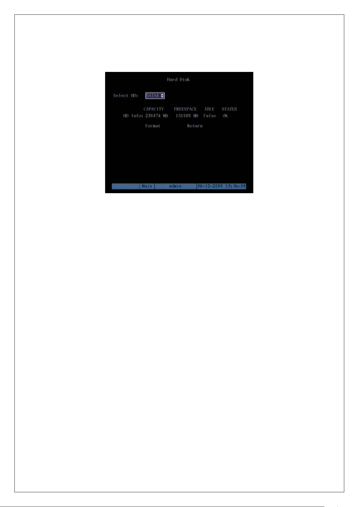
16
formatted a confirmation message will be shown on the screen. Ensure that all installed disks have
the status "OK".
Hard drive installation is completed.
Page 17
17
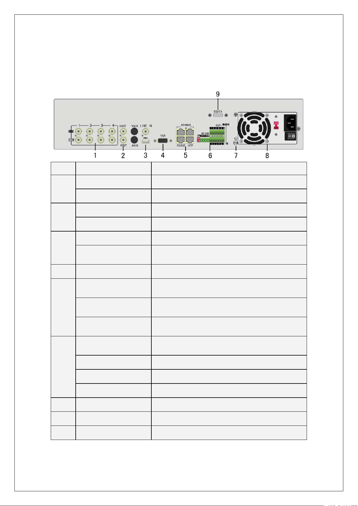
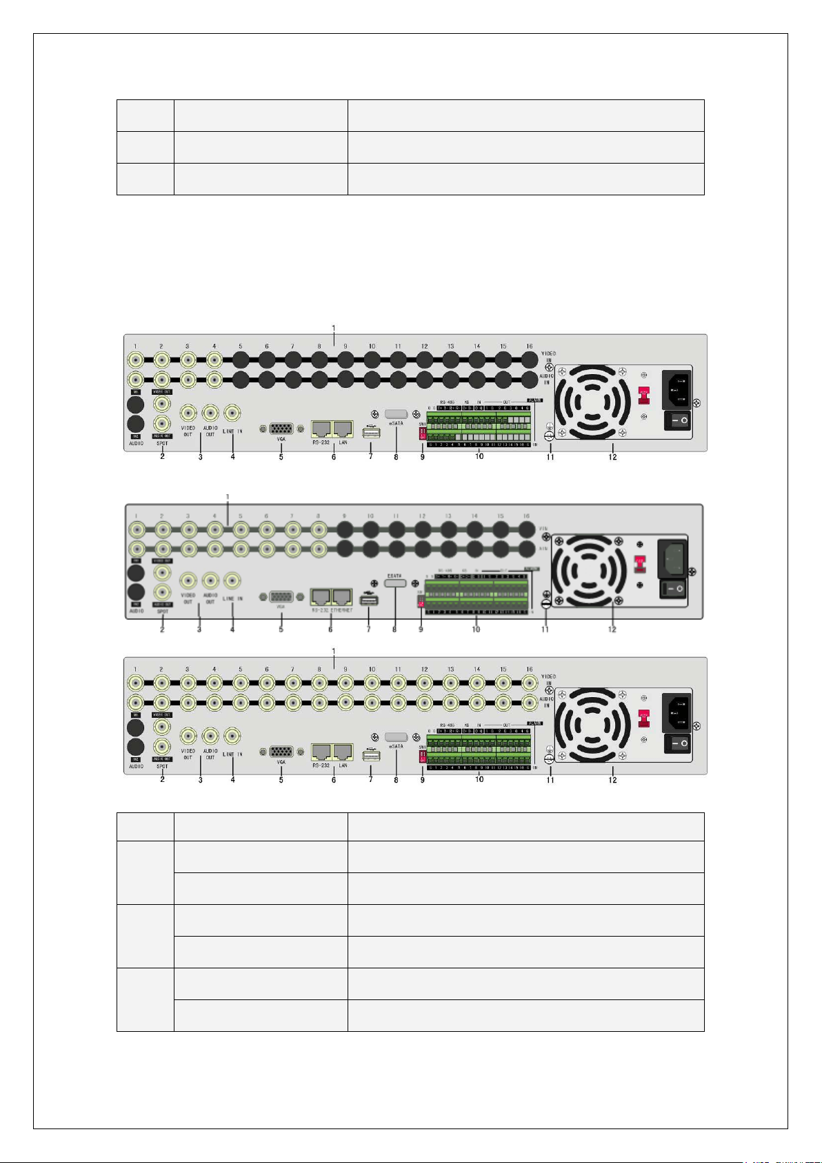
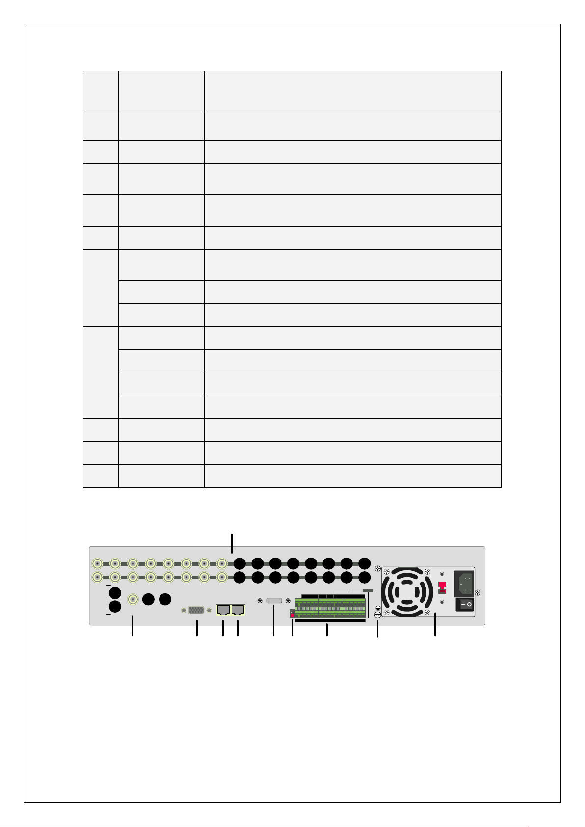
2.3 DS-8000HCI-S Rear Panel Connection
t is off. The
DS-8004HCI-S Rear Panel:
Index Physical Interface Description
Video input
1
Audio input
Main video output
2
Main audio output
Line in
3
USB interface
4
VGA interface
Keyboard interface
5
RS-232
Network Interface
SW1
Standard BNC
Standard BNC
Connect CCTV monitor, output video and menu
Local audio output
Audio line input for voice talk
USB memory disk, USB HDD, USB CD/DVD or USB
mouse
VGA display
One is for DS-1000KI keyboard, and the other is for DVR
cascade. Using Pin3 and Pin4
Connect RS-232 devices. Refer to Appendix B for pin
definition
Connect network devices. Refer to Appendix B for pin
definition
RS-485 terminal resistor switch. Defaul
resistor is 120Ω
6
7
8
9
RS-485
Alarm input
Relay output
GND
AC Input
E-SATA
PTZ connection. Using T+/T- to connect PT Z
4 sensor alarm in
2 relay outputs
Ground
100~240VAC
Optional. Extend 1st internal SATA to E-SATA.
Page 18
18
DS-8008HCI-S, DS-8016HCI-S Rear Panel:
ff. The
Index Physical Interface Description
Video input
1
Audio Input
Spot video output
2
Spot audio output
Main video output
3
Main audio output
4
Line in
5
VGA interface
RS-232
6
Network interface
7
USB Interface
8
E-SATA
Standard BNC
Standard BNC
Spot monitor for live video and playback
Spot monitor for live audio and playback
Main monitor for live video playback and menu
Main monitor for live audio and playback
Line input for audio
VGA display
Connect RS-232 devices. Refer to Appendix B for pin
definition
Connect network devices. Refer to Appendix B for pin
definition
USB flash memory, USB HDD, USB CD/DVD or USB
mouse
Optional. Extend 1st internal SATA to E-SATA.
9
SW1
RS-485
10
Keyboard interface
Alarm input
RS-485 terminal resistor switch. Default is o
resistor is 120Ω
PTZ connection. Using T+/T- to connect PTZ.
Using D+/D- for keyboard and DVR cascade connection.
16 sensor alarm in
Page 19
19
Relay output
4 relay outputs
11
12
GND
AC input
Ground
100~240VAC
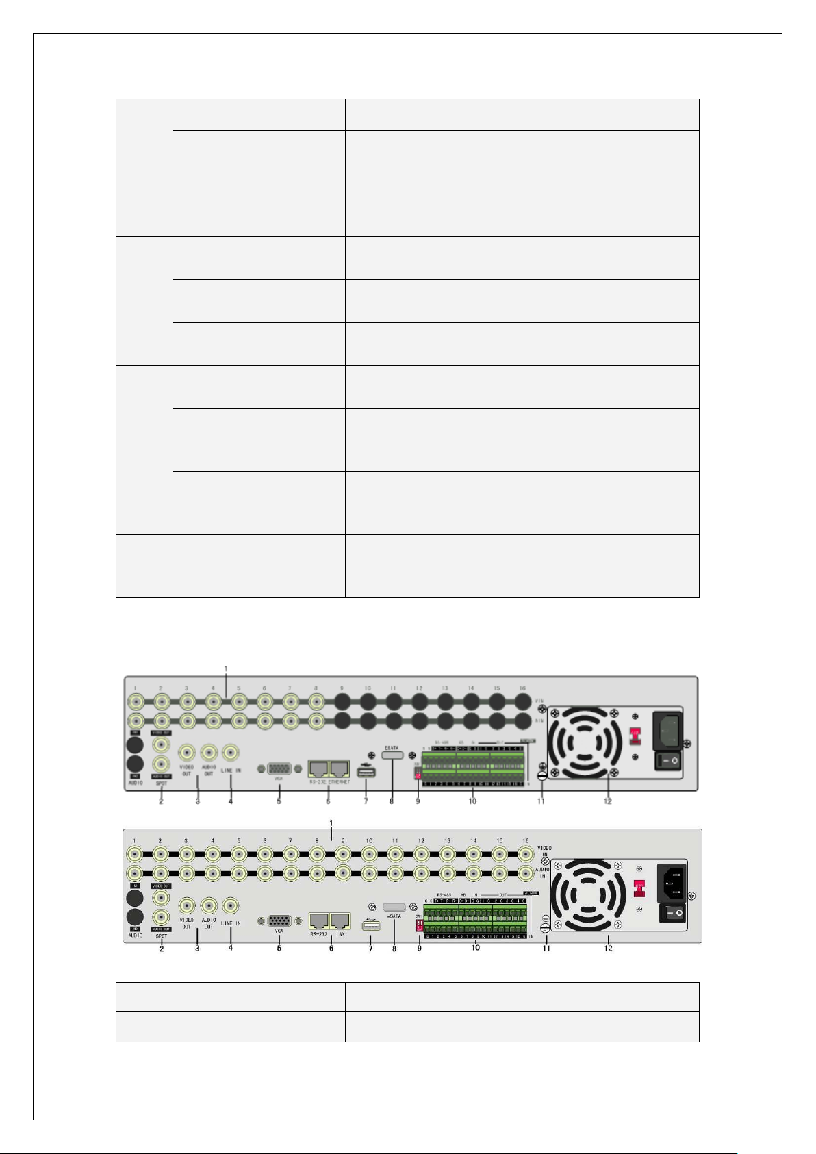
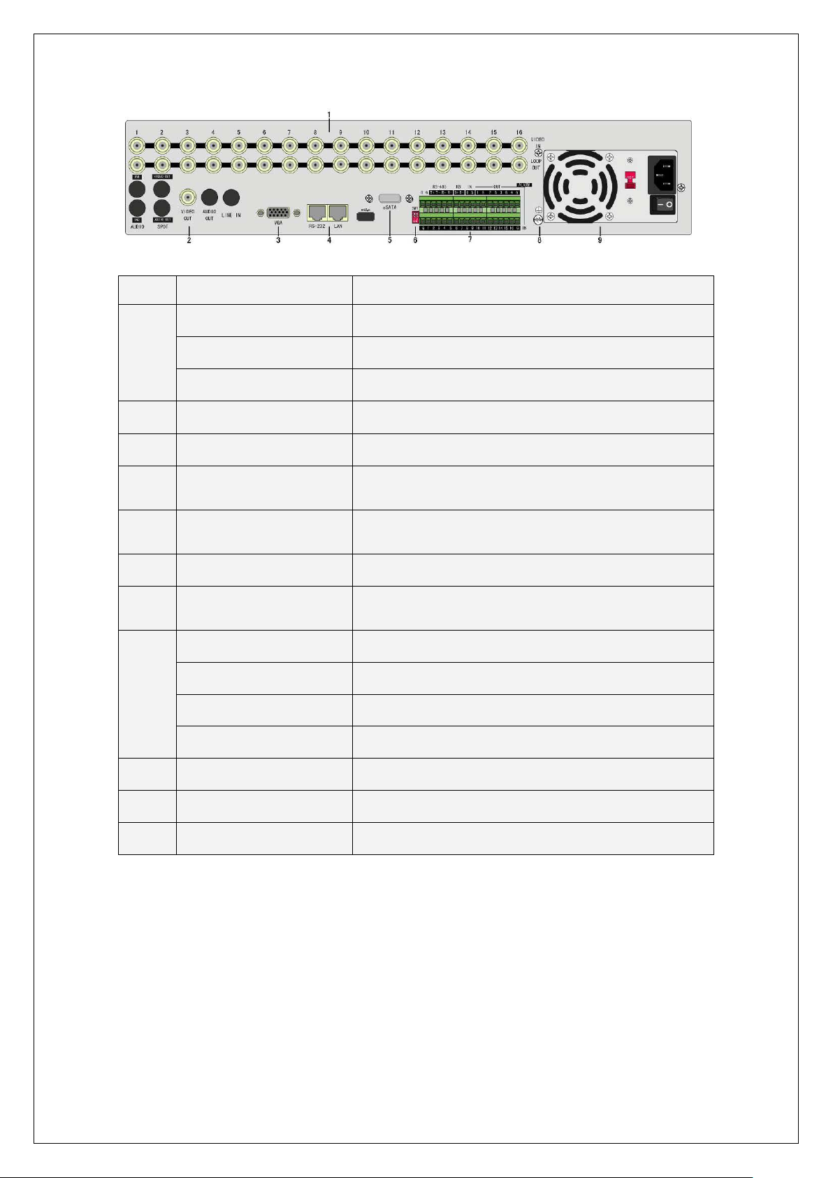
2.4 DS-8000HDI-S Rear Panel Connection
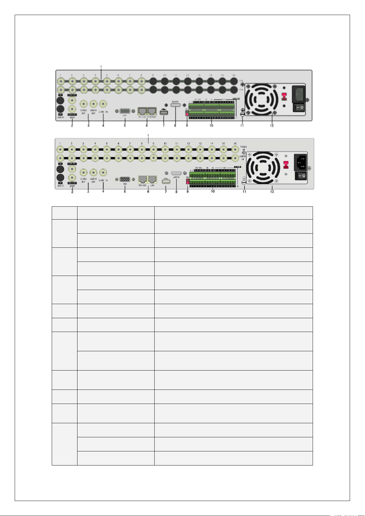
DS-8004HDI-S, DS-8008HDI-S, DS-8016HDI-S Rear Panel:
Index Physical Interface Description
Video input
1
Audio Input
Spot video output
2
Spot audio output
Main video output
3
Main audio output
Standard BNC
Standard BNC
Spot monitor for live video and playback
Spot monitor for live audio and playback
Main monitor for live video playback and menu
Main monitor for live audio and playback
Page 20
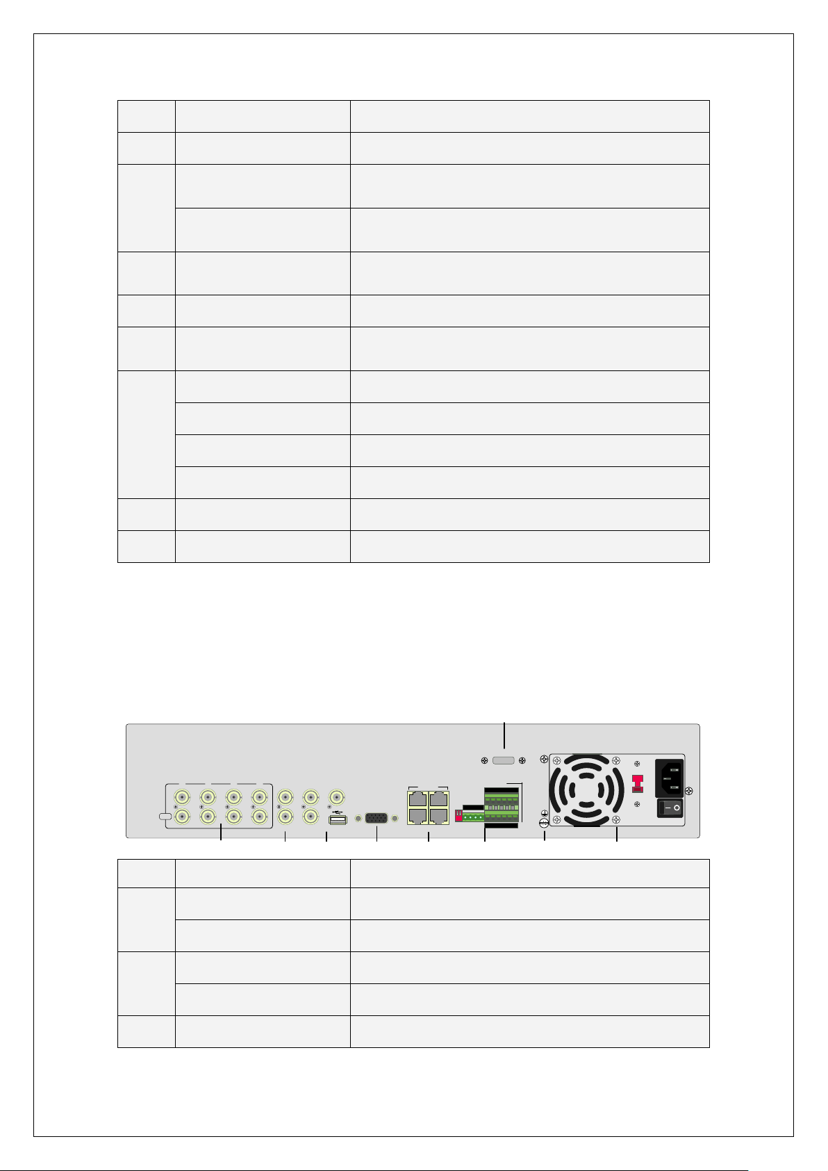
20
4
232 devices. Refer to Appendix B for pin
Connect network devices. Refer to Appendix B for pin
485 terminal resistor switch. Default is off. The
LINE IN
AAUX
VAUX
VGA
RS-232 UTP
70
706060
60604040
4040
230
7070
3
4 5 6
KEYBOARD
VOUT
AOUT
2
3 4 G G
2 G G G
1
1 G
1 2
ON
↓
SW1
2 3 41
VIN
AIN
2
1
RS-485
T+ T- R+R-
OUT
ALARM
IN
IN
ESATA
87
9
Line in
Line input for audio
5
6
7
8
9
10
11
12
VGA interface
RS-232
Network interface
USB Interface
E-SATA
SW1
RS-485
Keyboard interface
Alarm input
Relay output
GND
AC input
VGA display
Connect RS-
definition
definition
USB flash memory, USB HDD, USB CD/DVD or USB
mouse
Optional. Extend 1st internal SATA to E-SATA.
RS-
resistor is 120Ω
PTZ connection. Using T+/T- to connect PTZ.
Using D+/D- for keyboard and DVR cascade connection.
16 sensor alarm in
4 relay outputs
Ground
100~240VAC
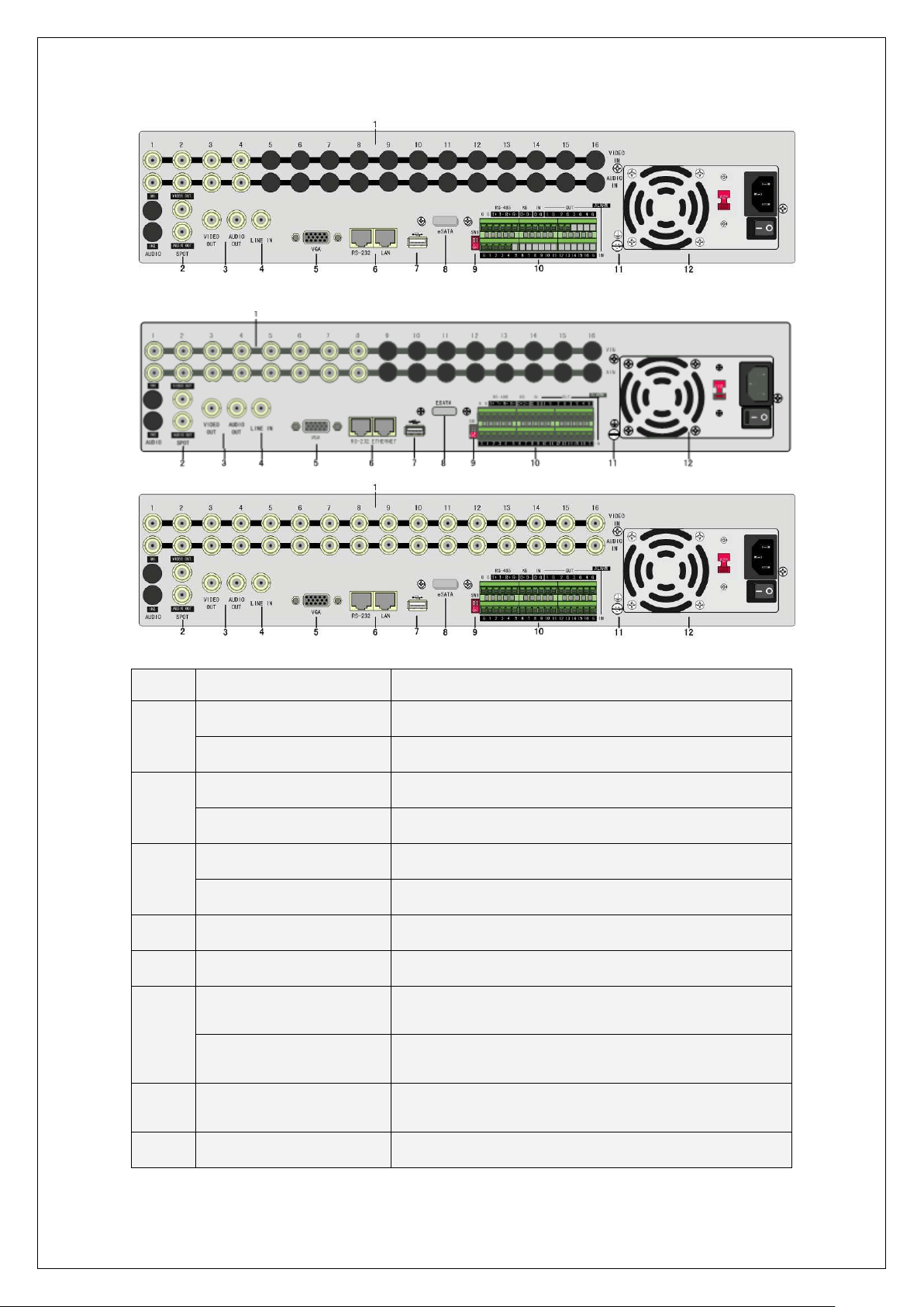
2.5 DS-8000HFI-S Rear Panel Connection
DS-8004HFI-S Rear Panel:
Index Physical Interface Description
Video input
1
Audio input
Main video output
2
Main audio output
Standard BNC
Standard BNC
Main monitor for live video, playback a nd menu.
Local audio output
3
Spot video output
Spot monitor for Live video and playback
Page 21
21
Spot audio output
Connect network devices. Refer to Appendix B for pin
ult is off. The
Spot monitor for live audio and playback
Line in
USB interface
4
VGA interface
Keyboard interface
5
RS-232
Network interface
SW1
RS-485
6
Alarm input
Alarm output
7
GND
Line input for audio
USB flash memory, USB HDD, USB CD/DVD or USB
mouse
VGA display
One is for DS-1000KI keyboard, and the other is for DVR
cascade. Using Pin3 and Pin4
Connect RS-232 devices. Refer to Appendix B for pin
definition
definition.
RS-485 terminal resistor switch. Defa
resistor is 120Ω.
PTZ connection. Using T+ T- to connect PTZ
4 sensor alarm in
2 relay outputs
Ground terminal
8
9
AC input
E-SATA
100~240VAC
Optional. Extend 1st internal SATA to E-SATA.
DS-8008HFI-S, DS8016HFI-S Rear Panel:
Index Physical Interface Description
1
Video input
Standard BNC
Page 22
22
Audio input
485 terminal resistor switch. Default is off. The
LINE IN
AAUX
VAUX
VGA
RS-232 UTP
70706060606040404040
230
7070
KEYBOARD
VOUT
AOUT
2 3 4 G G
2 G G G
1
1 G
1 2
ON
SW1
2 3 41
VIN
RS-485
T+T- R+R-
OUT
ALARM
IN
ESATA
↓
LOOP
1
2
3
4
5 6
7 8
9
10
Standard BNC
Spot video output
2
Spot audio output
Main video output
3
Main audio output
4
Line in
5
VGA interface
RS-232
6
Network interface
7
USB interface
8
E-SATA
9
SW1
RS-485
Spot monitor for live video and playback
Spot monitor for live audio and playback
Main monitor for live video, playback and menu
Main monitor for live audio and playback
Line input for audio
VGA display
Connect RS-232 devices. Refer to Appendix B for pin
definition
Connect network devices. Refer to Appendix B for pin
definition
USB memory disk, USB HDD, USB CD-R/W, USB DVD
or USB mouse
Optional. Extend 1st internal SATA to E-SATA.
RS-
resistor is 120Ω
PTZ connection. Using T+/T- to connect PT Z
Keyboard Interface
Using D+/D- for keyboard and DVR cascade connection
10
16 sensor alarm in
4 relay outputs
Ground
100~240VAC
11
12
Alarm input
Relay output
GND
AC Input
2.6 DS-8000HSI-S Rear Panel Connection
DS-8004HSI-S rear panel
Page 23
23
Index
Main video
lash memory, USB HDD, USB CD/DVD writer, or USB
1 2
ON
?
1 2 3 4 5 6 7 8
9
10 11 12 13 14 15 16
VIN
LOOP
OUT
VOUT
AOUT
AUX
VOUT
AOUT
LINE IN
SW1
VGA
RS-232ETHERNET
G G D+ D-
RS-485 KB IN
OUT
1 G 2 3 G 4 GG0 G
ALARM
IN
1 2 3 4 5 6 7 8 9 10
11 12 1314 1516
T+T- R+
R
-
G G
70
706060
60604040
4040
230
7070
ESATA
1
2
3 4
5
6
7
8
9
10
Physical
Interface
Description
1
Video Input
2
Video Loop out
3
Output
4
USB Interface
5
VGA interface
Keyboard
interface
6
RS-232
Ethernet
SW1
RS-485
7
Alarm input
Alarm output
Standard BNC.
Standard BNC.
Connect CCTV monitor, output video and menu.
USB f
mouse
VGA display.
One is for DS-1000KI keyboard, and the other is for DVR cascade.
Using Pin3 and Pin4.
Connect RS-232 devices.
Connect network devices.
RS-485 terminal resistor switch. Default is off. The resistor is 120 Ω.
PTZ connection. Using T+ T- to connect PTZ.
4 sensor alarm in.
2 replay output.
8
9
10
GND
AC input
E-SATA
Ground terminal
100~240VAC
Optional. Extend 1st internal SATA to E-SATA.
DS-8008HSI-S DS-8016HSI-S rear panel
Page 24
24
232 devices. Refer to Appendix B for pin
Connect network devices. Refer to Appendix B for pin
485 terminal resistor switch. Default is off. The
Index Physical Interface Description
Video Input
1
Video loop out
Aux audio Output
2
Main video output
3
VGA Interface
4
RS-232
5
Ethernet
6
E-SATA
7
SW1
RS-485
Keyboard Interface
8
External Alarm Input
Standard BNC.
Standard BNC.
Spot monitor for audio preview and playback.
Main monitor for video and menu.
VGA display.
Connect RS-
definition.
definition.
Optional. Extend 1st internal SATA to E-SATA.
RS-
resistor is 120Ohm.
PTZ connection. Using T+/T- to connect PTZ.
Using D+/D- for keyboard and DVR cascade connection.
16 sensor alarm in.
Relay Output
9
GND
10
11
AC Input
USB
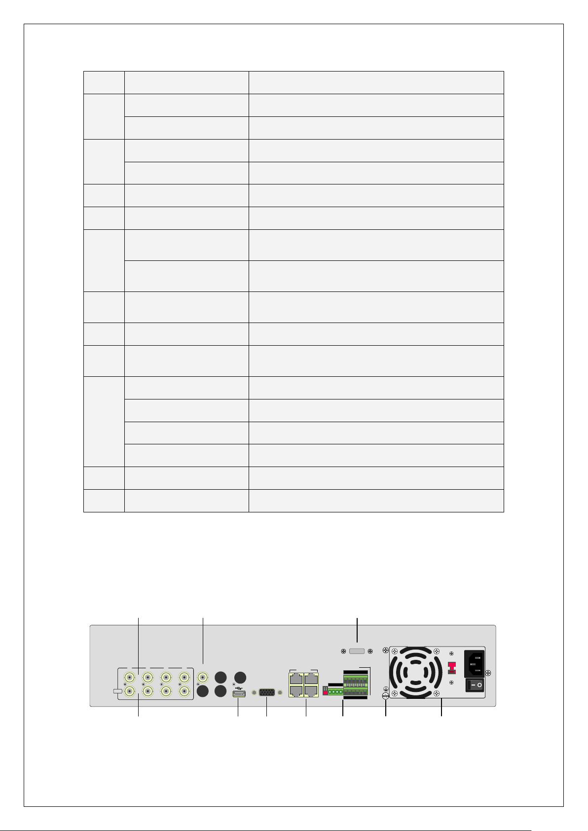
2.7 DS-8000HTI-S Rear Panel Connection
DS-8004HTI-S, DS-8008HTI-S, DS-8016HTI-S Rear Panel:
4 replay output.
Ground
100~240VAC
USB interface is on the front panel
Page 25
25
232 devices. Refer to Appendix B for pin
onnect network devices. Refer to Appendix B for pin
Index Physical Interface Description
Video input
1
Audio Input
Spot video output
2
Spot audio output
Main video output
3
Main audio output
4
Line in
5
VGA interface
RS-232
6
Network interface
7
USB Interface
8
E-SATA
Standard BNC
Standard BNC
Spot monitor for live video and playback
Spot monitor for live audio and playback
Main monitor for live video playback and menu
Main monitor for live audio and playback
Line input for audio
VGA display
Connect RS-
definition
C
definition
USB flash memory, USB HDD, USB CD/DVD or USB
mouse
Optional. Extend 1st internal SATA to E-SATA.
Page 26
26
9
485 terminal resistor switch. Default is off. The
SW1
RS-
resistor is 120Ω
RS-485
Keyboard interface
10
Alarm input
Relay output
11
12
GND
AC input
PTZ connection. Using T+/T- to connect PTZ.
Using D+/D- for keyboard and DVR cascade connection.
16 sensor alarm in
4 relay outputs
Ground
100~240VAC
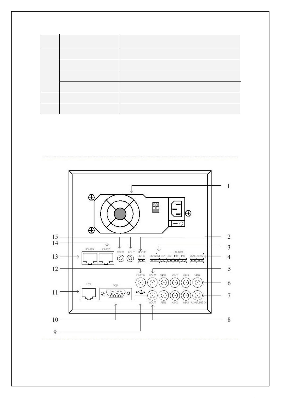
2.8 DS-8000AH(F)(L)I-S Series Rear Panel Connection
Take DS-8004AH(F)(L)-S Rear Panel for example:
Page 27

27
Index Physical Interface Description
mIn1 provides DC +12V/1A for sensor; Pin2
1
Power Adapter
2
Power Output
3
External Alarm In
Alarm Output
4
VOUT
5
VIN
6
AIN
7
ATX Standard. 220V or 110V option.
DC Output +12V/1A for camera.
Pin1 of Alar
is GND; Pin3 is used to connect approaching sensor.
AlarmIn2, In3, In4 and In5 are switch trip.
Out1: Pin1 provides DC +12V/1A output; Pin2 is GND.
Out2: Relay output (switch trip).
Local video output, BNC interface.
4 video input, BNC interface.
th
4 audio input, BNC interface. The 4
audio input is also
used as Line in for voice talk.
AOUT
8
9
10
11
12
13
14
15
USB Interface
VGA Interface
UTP Network Interface
Line In
RS-485
RS-232
Output for Backup
Audio output, BNC interface
Connecting USB memory disk, USB HDD, USB CD-R/W
Connecting VGA display.
Connecting network devices. Refer to Appendix B for pin
definition.
Use 4th audio input instead.
PTZ connection. Refer to Appendix B for pin definition.
Connecting RS-232 devices. Refer to Appendix B for pin
definition.
Connecting analog recording device for backup.
Page 28
28
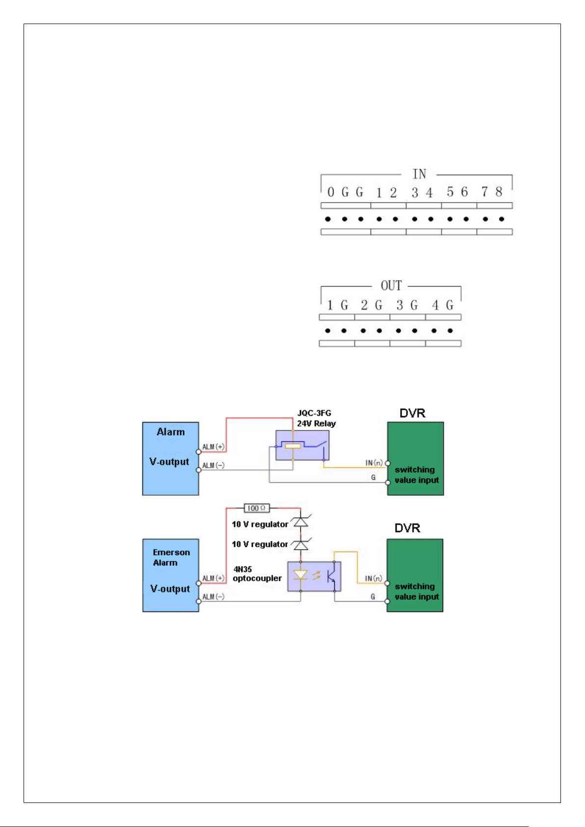
2.9 External Alarm In/Out Connection
1~8: Alarm input, support normal
Alarm input description:
Alarm input port (dry contact):
G (GND): Connect the GND of sensor.
open/normal close.
0: Reserved.
Alarm output:
1G~4G: 4 relay output.
The alarm input is switch signal,if the alarm input is not switch signal, such as voltage signal,
then please follow the connection method below.
Alarm output connection:
Page 29

29
Connect with DC device
Connect with AC device.
Please pay attention to the different application of JP4 in these applications. If the interface is
connected with DV load, JP4 can be used in these two methods safely, and suggest that this should
be used within the limit of 12V/1A. if the interface is connect with AC load, then JP4 should be
cut off, unplug the short circuit object. Please use external relay for safety. (as shown in the figure)
There are 4 short circuit objects in the mother board, every alarm output interface correspond
one of them, and they are JP4, JP5, JP6 and J P7. It is short ci rcui ted after th e DVR is produ ced, so
these short circuit objects should be unplugged when AC load is connected.
Attention! If the alarm output interface is used for control the AC circuit, short circuit
objects on mother should be unplugged, and external relay is needed to make sure the safety
of device, and prevent electric shock.
Cable connection
Device supplies the curved needle plug for signal cable connection, here is the process:
1. Unplug the green Curved needle plug in the ALARM IN and ALARM OUT interface;
Page 30

30
2. Un-fasten the screws in the curved needle plug, then put the signal cable into little metal
box and then fasten the screws.
3. Connect these curved needle plugs with the interface.
2.10 Power On
Note: Complete all cable connections before powering on the DVR.
1. Switch on all connected equipment.
2. Connect the power cable to the unit.
3. Switch on the power supply power switch.
Page 31

31
Chapter3 Operational Instructions
tus. Green means recording; Red
Device switch with power indicator lamp. Green means
; Red means DVR is powered off; No
Input number, lower case, upper case character and
[MENU] for 5 seconds to cancel
3.1 DVR Front Panel
1. T ake DS-8000HFI-S for example:
Index Type Name Description
1 IR receiver
2 Camera
indicator
Lamps
3 POWER POWER
4 Status
Lamps
5 Input keys Numeric
Function
1 - 16 Show 1-16 camera sta
means network transmission; Orange means recording and
network transmission.
DVR is operating
light means no power is supplied.
READY DVR is ready
STATUS Green means you can use IR remote control
ALARM Red means there is alarm
Modem Green means there is a modem connection.
HDD Flickering red means reading or writing HDD
LINK Green means there is a network connection
Tx/Rx Flickering green means data is being transmitted
Keys
F1 [LIGHT] in PTZ control
F2 [AUX] in PTZ control
MENU 1. Enter Menu (from live mode)
ESC Cancel and return to previous menu
symbols
2. Wiper control in PTZ mode
3. Press and hold
key-down tone
Page 32

32
(number, lower case, upper
keys PLAY 1. Local playback
6
2. [AUTO] in PTZ control
REC 1. Manual record
2. Preset in PTZ mode
EDIT 1. In edit state, delete the current cursor character
2. [IRIS+] in PTZ mode
3. Select or × to enable or disable
PTZ 1. Enter PTZ control mode
2. [IRIS-] in PTZ mode
A 1. Input character select
2. [FOCUS+] in PTZ mode
3. Display or hide the channel status bar (in live mode)
PREV 1. Multi screen selection
2. Switch menu mode into live view
3. [FOCUS-] in PTZ mode
INFO [ZOOM+] in PTZ mode
Main/Aux 1. Switch main/spot video output control mode
2. [ZOOM-] in PTZ mode
7 Control
Keys
Direction
Keys
Composed of [] , [], [] and []
1. Menu mode, use direction keys to select, press [Enter]
or [Edit] key for edit
2. PTZ direction control
3. Playback speed control
ENTER 1. Menu confirmation;
2. Select or × to enable or disable;
3. Pause playback.
case and symbol)
2. DS-8000AHI-S Front Panel
Page 33

33
network transmission; Orange means recording and network
network transmission; Orange means recording and network
network transmission; Orange means recording and network
network transmission; Orange means recording and network
Index Type Name Description
1 Status
Lamps
READY
STATUS
ALARM
MODEM
HDD
LINK
Tx/Rx
CH1
DVR is ready.
Green means you can use IR remote control.
Red means there is alarm.
Green means modem connection and dial-up successful.
Twinkle in red means reading or writing HDD.
Green means network is OK.
Twinkle in green means data is being transmitted
Channel1 working status. Green means recording; Red means
CH2
transmission.
Channel2 working status. Green means recording; Red means
CH3
transmission.
Channel3 working status. Green means recording; Red means
CH4
transmission.
Channel4 working status. Green means recording; Red means
transmission.
2 POWER POWER Device switch with power indicator lamp. Green means DVR
Page 34

34
3 Function
Press [MENU] for more than 5 seconds to cancel button
Input switch (number, lower case, upper case and
Keys
MENU
VOIP
INFO
ESC
EDIT
4 Shortcut
Keys
PLAY
REC
PTZ
PREV
A
5 Control
Keys
6 Control
Direction
Keys
ENTER 4. Menu confirmation;
Keys
7 Input Keys Numeric
Keys
is working; Red means DVR is powered off; No light means
no power is supplied.
3. Switch preview mode into menu;
4. Brush control short key【WIPER】.
5.
beep sound.
【ZOOM-】in PTZ control.
【ZOOM+】in PTZ control.
Cancel and back to parent menu.
4. In edit state, delete the current cursor character;
5. 【IRIS+】in PTZ control;
6. Select or × to enable or disable.
3. Local playback;
4. 【AUTO】in PTZ control.
3. Manual record;
4. 【SHOT】in PTZ control (adjust preset).
6. Enter into PTZ control mode;
7. 【IRIS-】in PTZ control.
4. Multi screen preview switch;
5. Switch menu mode into preview;
6. 【FOCUS-】in PTZ control.
4.
symbol);
5. 【FOCUS+】in PTZ control;
6. In preview mode, display or hide the channel status bar.
Composed of 【】,【】,【】 and 【】.
4. Menu mode, use【】/【】 to select,【】/【】 to
edit;
5. PTZ direction control;
6. Playback speed control.
5. Select or × to enable or disable;
6. Pause playback.
Input number, lower cas e, u pper case character and symbols.
3. DS-8000AHLI/AHFLI-S Front Panel
Page 35

35
The lamp is on means you can use compound keys as
numeric keys to input numeral or English characters. The
lamp is off means the compound keys can be used as
n means recording; Red
means network transmission; Orange means recording and
Channel2 working status. Green means recording; Red
means network transmission; Orange means recording and
Index Type Name Description
1 Status
Lamps
POWER
READY
STATUS
ALARM
MODEM
HDD
LINK
Tx/Rx
Power indicator lamp. Green means DVR is working; Red
means DVR is powered off. No light means no power is
supplied.
DVR is ready.
Green means you can use IR remote control.
Red means there is alarm.
Green means modem connection and dial-up successful.
Twinkle in red means reading or writing HDD.
Green means network is OK.
Twinkle in green means data is being transmitted
NUMLOCK
CH1
function keys. You can use【SHIFT】key to switch.
Channel1 working status. Gree
CH2
network transmission.
network transmission.
Page 36

36
CH3
een means recording; Red
means network transmission; Orange means recording and
Channel4 working status. Green means recording; Red
means network transmission; Orange means recording and
Channel3 working status. Gr
network transmission.
CH4
network transmission.
2 Control
Keys
Direction
Keys
ENTER
Composed of 【】,【】,【】 and 【】.
1. Menu mode, use【】/【】 to select,【】/【】
to edit;
2. PTZ direction control;
3. Playback speed control.
1. Menu confirmation;
2. Select or × to enable or disable;
3. Pause playback.
3 POWER POWER Power switch.
4 Switch
Key
5 Compound
Keys
SHIFT Switch between function keys and numeric keys. The lamp
of NUMLOCK will display the status.
MENU/1
VOIP/2
INFO/3
ESC/4
EDIT/5
PLAY/6
REC/7
PAN/8
PREV/9
A/0
Composite of【MENU】and【1】.
Composite of【VOIP】,【2】and【ABC】.
Composite of【INFO】,【3】and【DEF】.
Composite of【ESC】,【4】and【GHI】.
Composite of【EDIT】,【5】and【JKL】.
Composite of【PLAY】,【6】and【MNO】.
Composite of【REC】,【7】and【PQRS】.
Composite of【PAN】,【8】and【TUV】.
Composite of【PREV】,【9】and【WXYZ】.
Composite of【A】and【0】.
6 LCD Display For local display.
Page 37

37
3.2 IR control
Index Name Description
1 POWER Power DVR on/off
2 DEV Enable/Disable IR remote control
3 Numeric Keys Same as numeric keys on front panel
4 EDIT Same as [EDIT] key on front panel
5 A Same as [A] key on front panel
6 REC Same as [REC] key on front panel
7 PLAY Same as [PLAY] key on front panel
8 INFO Same as [INFO] key on front panel
9 VOIP
10 MENU Same as [MENU] key on front panel.
11 PREV Same as [PREV] key on front panel.
12
Direction Keys
ENTER
Same as [Main/Aux] key on front
panel.
Same as direction keys and enter key
on front panel
13 PTZ Same [PTZ] key on front panel
Page 38

38
14 ESC Same as [ESC] key on front panel
15 Reserved Reserved for future use
16 F1 Same as [F1] key on front panel
17 Lens control IRIS, FOCUS ZOOM for lens control
18 F2 Same as [F2] key on front panel
Loading the batteries into the IR controller:
1. Remove the battery cover.
2. Insert the battery. Ensure that the poles (+ and -) are correctly positioned.
3. Replace the battery cover.
Enable the IR Remote Controller:
1. Press the [DEV] key, input the DVR device ID (default is “88”. It can be changed in the
“Display” menu) and then press the [ENTER] key.
2. The “STATUS” lamp on the DVR front panel will turn green, in dicating that you can use
IR controller to operate the DVR.
Disable the IR controller:
1. When IR controller status lamp is on, press the [DEV] key.
2. The “STATUS” lamp on the DVR will turn off. The IR controller won’t control the DVR.
Turn off the DVR:
1. When IR controller status is on, press the [POWER] key for several seconds.
2. The DVR will be powered off.
Troubleshooting the IR Remote:
1. Always aim the IR Remote controller at the DVR you want to control.
2. Make sure that the correct DVR ID code is entered and the status lamp on the DVR is
green.
3. Check the batteries.
4. Make sure nothing is obstructing the IR sensor on the DVR.
5. Try another IR Remote control.
Note: If you have only one Remote unit to work w ith it is often di fficult to verify whe ther the unit
is actually working. Humans can’t see the IR LED flashing on the remote when keys are pressed.
Cameras can see the LED flash. Aim the Remote at a conveniently placed camera and you can see
the LED lash on the monitor.
Page 39

39
3.3 OSD Menu Description
3.3.1 Main Menu Items
Menu Name Function Menu Name Function
Display
Recording
Alarms
PTZ
Preview
Transact
Unit Name
Device ID
Require Password Y/N
Screen saver
Video standard
Enable Scaler
Brightness
Menu transparency
VGA resolution
DST
Date and Time
Overwrite/Stop recording
SATA1 disk usage
Recording parameters
Record schedule
Prerecord time
Post Record time
Alarm input type (NO/NC)
Alarm response and PTZ linkage
Alarm output and schedule
PTZ parameters
Preset setup
Sequence setup
Pattern setup
Out channel
Preview mode
Switch time
Audio preview
Alarm out
Display delay, Lay out
Through mode
Local port
Image
Network
Exceptions
RS232
User
Utilities
Select Camera
Camera name and position
Brightness, Contrast, Hue,
Saturation adjust
OSD Display mode, position and
OSD style setup
Privacy Mask area setup
View tampering area and response
setup
V ideo si gn al l oss
Motion detection sensitivity, area
and response setup
DVR IP address
DNS IP
Advanced settings
Multicast IP address
Remote host IP and port
PPPoE setup
E-mail
Exception
Handle Method
RS232 parameters
Add or delete user
Password setup
User rights setup
Save parameter
Restore factory parameters
Upgrade firmware
HDD management
Page 40

40
Stop alarm output
Reboot
Power off
View log
System information
3.3.2 Navigating Menus in DS-8000 series DVR
The Operation Manual provides step by step instructions in the early chapters. The later
chapters provide directions without indicating some of the individual key presses because you
will have learned the basics by then. This section provides a brief overview of navigating
through the menus using the control keys and by using the mouse. With this information you
will be able to quickly access most DVR functions. See the detailed text for further
information on particular features.
There are several methods to control the DVR.
• Front Panel Control.
• IR Remote Control.
• Mouse Control.
• Remote Software Control.
The details in the manual concentrate on the Front Panel control method. The IR Remote
control operation is essentially the same using the remote device. There are a few differences
that are mentioned in the manual. Mouse control is an option that can be used, but is not
mentioned throughout the manual. The remote software is addressed in a separate manual.
Mouse Control: There are some things to consider whe n using a mouse with the DVR. A
USB mouse is used. There is one USB connection on the rear panel of the DVR. A USB port
expander may be used to add additional USB connectivity to the DVR. This could be helpful
in exporting files to a USB device and when updating the firmware. Do not place a mouse pad
on the top cover of the DVR as this may block the access holes and cause air flow restriction
and heat buildup that may cause damage to the unit.
Most DVR operations can be performed using the mouse. If you are close enough to the unit
to use a mouse you will also be able to use the front panel and IR Remote keys for operation.
You will decide which operations are more easily performed with each control method.
In Live View control:
Double click the left mouse key on an individual camera cameo in a multi-screen display to
go to full screen. Double click again to return to the previous multi-screen display. A right
mouse click produces a pop-up menu that provides access to a large number of features.
Page 41

41
• Main Menu: Provides access to the DVR Menu.
• Single: Allows selection of any full size camera display.
• Multi-Preview: Select “Live View” of 4, 9, 12, or 16 channel multi-screen modes.
• Next Preview: Selects the next sequential display (ex. In four-channel: 1-4, 5-8, etc.).
• PTZ Control: Access PTZ camera control.
• Play: Enter playback mode.
• Manual Record: Access the Manual Record Menu.
• Close Status: (Open status): Show/hide the status line on the monitor.
• Switch VOUT : Switch to the “Spot” monitor output.
Caution: If you select “Switch VOUT” you will lose mouse control of the main monitor. The
mouse pointer will move to the Spot display. If you have a monitor connected to the “Spot”
output you can right click and se lect “Switch VOUT” to retu rn to the main display control. If
no “Spot” monitor is available you will not be able to return to the main output using the
mouse. You must press the “Main/Aux” key on the front panel, or the “VOIP/MON” key on
the IR Remote. The same issue is present when using front panel and IR Remote operation. If
the Spot monitor is inadvertently selected (by pressing the appropriate key) when there is no
Spot monitor installed, it will appear as if the uni t is not oper a ting properly.
General Mouse Menu Navigation: A standard left mouse click will select most options. Just
position the mouse over the desired menu item and select. A “right mouse click” pops-up an
option list (from the live displ ay) . Onc e in the menu , a rig ht cl i ck wil l tak e yo u to the prev io u s
menu. Walk through the following list of items to familiarize yourself with mouse operation.
Starting from the live display:
• “Right-click” the mouse to view the control options and then and select “Main Menu.”
• You can click on any of the options to enter sub menus.
• Click to select the Display Menu and view the available options.
• Additional mouse clicks will select any menu option and/or change the status of the check
boxes.
• Select the “Setup” button next to time/date. You are now in a “Sub, Sub menu.”
• Click on the “Day” window next to “Date.” The pop up box allows you to change the
number entry. Just click on the numbers you want (don’t forget leading zeros).
• Always remember to navigate to the “Confirm” button and press “Enter” to update your
selections. Otherwise the selections will not be updated.
• A “right click” will take you back to the previous menu; first to the “Display” menu,
another “Right click” to the Main Menu and another takes you back to the live display.
There are some situations where mouse operation may seem erratic (especially if you use the
scroll button) but a little practice can make this a preferred method for controlling the DVR.
Control from the Front Panel Keys:
Front Panel: All DVR functions are controllable from the front panel keys. Reaching the front
Page 42

42
panel may be difficult in some installations so the IR Remote is a good alternative when the DVR
is in sight, but not in reach.
Function Keys:
• MENU: Enter the DVR Menu.
• ESC: The escape key returns to Live mode, or to a previous menu.
• PLAY: Enters Playback.
• REC: Enters Manual Record Menu.
• EDIT: Selects the next sequential display (ex. In four-channel: 1-4, 5-8, etc.) in
Live Mode. Change sel ections in Menu Mode.
• PTZ: Enter camera control mode. (All function buttons are used for PTZ functions
when in PTZ Mode. See the red ti tling under each key for its PTZ function). Press
“ESC” to exit PTZ mode and restore normal function key operation.
• A: Show/hide the s tatus line on the monitor in Live Mode. Scroll throu gh character
entry options in Menu Mode.
• PREV: Toggle “Live View” of 1, 4, 9, 12, or 16 channel multi-screen modes.
• MAIN/AUX: Toggle between Main monitor and Spot monitor control modes.
General Front Panel Key Menu Navigation: Press the “Menu” key to enter the Main Menu.
Moving the Active Window (highlighted cursor) is done by pressing the direction keys (Up,
Down, Left, Right) and item selection is done with the “Enter” (center of arrow keys) key (or
the EDIT key). Once in the menu, “ESC” will take you to the previous menu and back to live
mode. Walk through the following list of items to familiarize yourself with key operation.
Starting from the live display:
• Press the “Menu” key to enter the “Main Menu.”
• Use the Up/Down arrow keys to enter sub menus.
• Select the Display Menu to view the available options.
• Use the arrow keys to move to selected menu options and press “Enter” to select. Enter
(or, Edit) will also change check box selections.
• Select the “Setup” button next to time/date. You are now in a “Sub, Sub menu.”
• Select the “Day” window next to “Da te” (arrow keys, then Enter). Use the number keys
to enter your numerical selections and press “Enter.”
• Always remember to navigate to the “Confirm” button and press “Enter” to update your
selections. Otherwise the selections will not be updated.
• Press “ESC” to take you back to the previous menu; first to the “Display” menu, “ESC”
again to the Main Menu and again to return to the live display.
Page 43

43
3.3.3 Menu Operation
How to access the menus:
• Press the [MENU] key to enter the DVR main menu
• Press the [PLAY] key to enter the playback menu
• Press the [REC] key to enter the manual record menu
• Press the [PTZ] key to enter the PTZ control interface
Note: You must input a valid user name and password. The default user name is “admin” and
password is “12345”.
Main Menu Description:
Main menu:
One section of the menu screen will be highlighted to indicate the input cursor position. The
Active window can be moved from one item to another by using the direction keys ([↑] [↓] []
[]). When the “Active Window” is located on an item, you can press the [ENTER] key to enter
the sub menu. For example: Move the “Active Window” to “Image” and press [ENTER] to enter
the secondary menu as follows:
Page 44

44
Each sub-menu contains several related items. Select the entry desired.
1. Check Box: Provide 2 options. “” means enable and “×” means disable. Select
either [ENTER] or [EDIT] to change selections.
2. List Box: Provides more than 2 options. However, only one of them can be selected.
You can press [ENTER] or [EDIT] to enter edit mode, then use [↑] and [↓] to select
one option. For example, on the right side of “Select Camera”, there is a list box for
you to select one camera.
3. Edit Box: Allows you to input characters. Press the [EDIT] key to enter the edit
mode. You can input characters as follows:
(1) Press the [A] key to select the entry mode (numbers, upper case, lower case or
symbols).
(2) Use [] and [] keys to move the cursor.
(3) Use the [EDIT] key to delete the character in front of the cursor.
(4) Press [ENTER] or [ESC] to exit the edit mode.
4. Button: Execute a special function or enter the next s ub-menu. For example, press
the “Policy” button to enter sub-menu. Press [Confirm] to save parameters and
return to the previous menu. Press the [Cancel] key to cancel and return to previous
menu. Grayed-out buttons indic ate the y can be operated only after another selection
is enabled.
Exiting the Menu: Press [ESC] to exit the menu and return to live view mode.
Page 45

45
3.4 Character Input
There is a status line at the bottom of all character entry screens. For example: In the “camera
name” edit box the following status line appears at the bottom of screen.
The word ”Number” indicates that you can use the numeric keys to input numbers.
Press the [A] key to change input modes. Available options are “Number”, “Uppercase”,
“Lowercase” and “Symbol”.
Uppercase
Lowercase
Symbol
There are 24 symbols in all. They are div ided into 4 pages. You can press the [0] key to scroll
through the available selections.
Note: The character input scheme may seem difficult until you become familiar with its operation.
All setup procedures may be accomplish from the remote software using a more familiar Windows
format.
Page 46

46
Chapter4 Basic Operation Guide
4.1 Power on
Note: It is always a good idea to check the power supply before connecting the AC cable and
applying power. The DS8000 is equipped with a universal power supply that will accommodate
120/240VAC, 50/60Hz. Units with an input power selector switch must be placed in the correct
input voltage position for the local area before applying power. Switch the main power switch off
before inserting the AC power cord. Connect a monitor (VGA, or co mposite) to view the GUI and
setup the unit.
If the [POWER] lamp is off, please do as follows:
1. Make sure the power cord is connected to an active power source.
2. Switch on the power key on the real panel.
If the [POWER] lamp is red:
1. Press the [POWER] key to start the DVR.
2. The power lamp will turn gr een as the unit powers up.
3. The DSP and HDD initialization process will be shown on the monitor.
The graphic includes two lines. The first line indicates the DSP hardware and the second
lists the available drives installed. A check mark (√) indicates correct operation of the
DSP and the presence of a disk drive installed in one of the eight available drive locations.
An “X” indicates improper operation or an uninstalled drive.
Note: If no drives are installed or detected, a “No Disk” message will display.
Page 47

47
4.2 Live View
At startup, the DVR will enter the live view mode. On the live display you will see the date/time,
camera name and camera/alarm status line in addition to the video from attached (and configured)
cameras. The information in the status line is described later in this manual. You can easily toggle
the status line on/off by right clicking the mouse and selecting “Show” or “Close” status, or press
the “A” key on the DVR front panel or IR Remote.
On the live screen, you will see date, time, camera names and camera status icons.
Note: To set the system date and time in “Display” menu, refer to section 6.4. To c hange camera
names in the “Image” menu, refer to section 6.5.
See the following chart for cam er a record s tatus indications:
Icon Icon Color Status Description
White No video signal
Yellow Video input
Pink Manual recording
Green Continuous recording
Page 48

48
Blue Motion detect recording
Red External alarm recording
See the following chart for alarm status indications:
Icon Icon Color Status Description
White V ideo sign al l os t
Yellow View tampering alarm
Pink Motion & External alarm
Green No alarm
Blue Motion alarm
Red External alarm
Press the numeric keys to switch to an individual camera in live view. If the DVR has less than 10
channels, press one numeric key to switch to the corresponding channel. For example: Press [2] to
view camera #2.
If the DVR ha s 10 or more 10 channels, press two numeric keys to switch to the corresponding
channel. For example: Press [0] [2] to select camera #2. Press [1] [2] to select camera #12.
Page 49

49
Press the [EDIT] key to manually sequence live views. You can set auto preview mode in the
menu (refer to section 5.2).
Press the [PREV] key to switch multi-screen views.
Press the [Enter] key to pause/resume sequence live view.
Page 50

50
4.3 Login
Note: The DVR factory default user name and password is “admin” “12345”. “admin” is the
administrator which allows access to all of the DVR functions, it cannot be renamed. The
administrator can create up to 15 individual users and ap ply indi vi du al privileges to each,.
Press the Menu key and the Login dialo g appears.
1. Use the [] / [] keys to select a user.
2. Press the [] key
Press [ENTER] to exit edit box. The “Active Window” will move to the “Confirm”
button.
3. Press [ENTER] to confirm the entry.
Note: An incorrect user name/password entry will result in an audible alarm. After three incorrect
entries the DVR will switch to the live display mode.
to enter the “Password” edit box. Input the corresponding password.
Page 51

51
4.4 PTZ Control
Note: Ensure that PTZ communication parameters have been configured properly before
attempting normal operation. Your password must have PTZ control enabled in order to control
cameras. Please refer to “PTZ Setup” in section 6.14.
Entering the PTZ control interface:
In live mode, press the [PTZ] key. In the login dialog, select a user name and input the correct
password. In menu mode, press the [PTZ] key and you will enter the PTZ control interface
directly.
There is a “PTZ Control” prompt in the PTZ control interface. The displayed camera name
indicates the camera under control. For example, “Camera 01” means you are controlling PTZ
camera #1.
Select the desired channel:
In the PTZ control mode, you can press the numeric keys to select the desired channel (Ex:
“0,””1,” for camera #1 – or “1” if using a 4/8 channel unit).
After you select the camera PTZ, you can use the shortcut keys to control the PTZ.
Page 52

52
PTZ Control Options:
Direction control keys: [↑], [↓], [←], [→]
ZOOM control keys: [ZOOM+], [ZOOM-]
FOCUS control keys: [FOCUS+], [FOCUS-]
IRIS control keys: [IRIS+], [IRIS-]
Adjust preset keys: [REC/SHOT];
Auto control key: [PLAY/AUTO]
Wiper control key : [WIPER/MENU]
Light control key: [LIGHT/F1]
Auxiliary control key: [AUX/F2]
Calling Preset positions:
In the PTZ control mode, press the [REC/SHOT] key, and then enter the preset number (three
numeric keys). The camer a will go to the cor r es p on din g preset position.
Setting Preset Positions:
To set a camera preset position, move the camera to the desired position. Press and hold the
[REC/SHOT] key while entering the preset number.
Note: A preset must be established before you will be able to call the preset in normal operation.
Refer to PTZ menu for preset setup.
When you exit PTZ control mode, the camera will stay at the current position (depending on the
dome used. Some domes may select a return to home position after a predetermined time).
Start/Stop auto PTZ control mode:
In PTZ control mode, press the [PLAY/AUTO] key to start the PTZ auto function. Press the
[PLAY/AUTO] key again to stop.
Note: When PTZ is in auto mode it will stay in auto mode when you exit the PTZ mode. You must
enter PTZ control mode again, and press the [PLAY/AUTO] key to stop.
Exit PTZ control mode:
Press [ESC] or [ENTER] to exit and return to the live view mode.
Page 53

53
4.5 Manual Record
Note: In order to perform this function the DVR must have drives installed and formatted and the
user login password must have “Record” enabled. Manual record will lose effective after reboot.
Manual record:
1. In the live view mode, press the [REC] key. In the pop-up login dialog, select a user name
and input the correct password to enter the “Manual Record” interface.
2. In menu mode, press [REC] to enter the “Manual Record” interface directly.
Manual Record Menu:
The Manual Record interface has the following selections: Channel number, channel status,
start/stop record, start all and stop all buttons.
1. Channel: Indicates available camera inputs.
2. Status: Indicates one of four settings:
recording (or set to record including: Continuous recording, alarm recording, motion
detection recording). Red means network transmission. Orange means both recording and
network transmission.
3. Start/Stop: “” means start recording corresponding channel. “×” means stop recording.
means idle. Green means the channel is
Page 54

54
4. Start All: Press this button to start all channels recording.
5. Stop All: Press this button to stop all channels from recording.
Note: Manual recording will loss effective after reb oo t.
Exit manual record:
Press the [ESC] key to enter the live view mode. Press the [MENU] key to enter the main menu.
Press the [PLAY] key to enter playback menu. Press the [PTZ] key to enter the PTZ control mode.
Page 55

55
4.6 Playback
Note: The user must have “Playback” permission associated with the user name and password in
order to enter playback mode.
Playback interface:
In the live view mode, press the [PLAY] key. In the pop-up login dialog, select a username and
input the correct password to enter the “Playback” interface.
In the menu mode, press the [PLAY] key to enter “Playback” interface directly.
Playback Menu:
The Playback interface has the following selections: Chan: Rec. Type, Time selection,
Search, Play, Select page, File list box, Backup devices, Copy and Backup Today.
1. Main Channel: Use the [↑] or [↓] key to select one channel.
2. Second Channel: If the DVR supports 2-ch playback (except DS-8008HCI-S,
DS-8016HCI-S & DS-8000HSI-S Series), you can use the [↑] or [↓] keys to select the
second channel (other than main channel). These two channels can be played back
synchronously. If you select the second channel as none, only the main channel will
playback.
Page 56

56
3. Rec Type: Use [↑] or [↓] to select recorded files type. The file type options have “All”,
“All Time”, “Motion Detect”, “Alarm” and “Manual”.
4. Time Selection: You can define the search time section. Move “Active Frame” to the
time edit box, use numeric keys to input the detail time.
5. Search: Search the matched recorded files and display them in the list box. If there is not
matched file, a corresponding dialog box will be pop-up.
6. Play by Time: Playback the recorded stream directly based on the time section.
7. Select Page: In the file list box, each page will only display 8 files. If the matched files
are more than 8, you can select page to list other files. 500 pages (4000 files) can be
searched in one time. You can use numeric keys or [↑] [↓] keys to select page.
8. File List Box: List the matched files. File started time, file size are displayed in the list
box. You can use [↑] [↓] keys to move the scroll bar to select file.
9. Backup Devices: You can select USB flash, USB HDD, USB CD/DVD or SATA
CD/DVD to backup the files or clips.
10. Copy: Start to backup.
11. Backup Today: Backup all recorded files of today.
Two playback modes:
1. Search and playback a file: In the playback menu select a channel to search, and a
record type. Move the “Active Window” to the “Search” button and press [ENTER]. The
DVR will search and list the matched files.
2. Playback by Time: In the playback interface, select a start and an end time using the
time entry boxes and then select the ”Play” button. Video playback will start from the
start time selected.
Page 57

57
One channel search
If there are more than eight matched files, use “Page No.” to select additional pages (use numeric
keys or [↑] [↓] keys to select a page). In the file list box, use the [↑] [↓] keys to move the scroll bar
to the desired file and press [ENTER] to playback the file. If a second channel is selected, these
two channels can playback synchronously.
Note: If no file match is fou nd, a message dialog will display indicating that no matching files
were found.
One-Channel Play-back
Page 58

58
Two-Channel Play-back
There is an information bar at the bottom of the display with the following information: Volume,
Play Progress, Play Speed, Played Time and File Total Time. The following front panel playback
controls are available:
1. Display/Hide information bar: [MENU]
2. Open/Close sound: [PLAY]
3. Adjust play progress: [←] (Backward), [→] (Forward). The unit is “%”.
4. Adjust play speed: Normal speed is “1x”. Use [↑] to increase play speed (2X, 4X, 8X
and MAX). Use [↓] to decrease play speed (1/2X, 1/4X, 1/8X and Single Frame). When
in “Single” pressing [ENTER] moves forward one image (single step).
5. Pause/Continue: Press [ENTER] to pause/continue playback.
6. Copy segment: [EDIT] to start copy, [EDIT] again to end copy.
7. Exit: [ESC]
8. Playback switch: When in 2-ch playback, press [PREV] to switch between main channel
and second channel.
When in the single playback mode, you can press [REC] button and use [←] [→] [↑] [↓] buttons
to select an area, then press [ENTER] button, the selected area will be enlarged in 4 times. You
Page 59

59
can press [REC] button to get back to normal playback interface.
Note: When the DVR is performing multiple tasks the actual play speed may not match the
selected speed.
Exit playback:
1. From the playback interface, press [ESC] to return to the Live mode.
2. From the playback interface, press [MENU] to enter main menu.
3. Press [REC] to enter the manual record menu.
4. Press [PTZ] to enter the PTZ control mode.
Page 60

60
4.7 Backup Recorded Files
Note: The user must have “Playback” permission associated with the user name and password in
order to enter playback mode and back-up files.
Some applications require data to be saved for a long period of time. The required information
could range from a short video clip up to the entire database. This section addresses ways to
export video from the DVR.
Back up selected files:
1. From the “live” mode, press [PLAY].
2. Enter a valid user name and password to enter the Play Back Menu.
3. Search files as indicated in section 4.6.
4. Select a file in the file list box.
5. Select the “Save Device” (USB flash memory, USB HDD, USB CD/DVD, SATA
CD/DVD or SATA HDD).
6. Select “Copy.” A pop-up dialog box will indicate that the file copy is in progress and
when the file copy is completed.
Backup intraday recorded files:
1. In the playback interface, select the “Backup Today” button and press [ENTER].
2. All intraday recorded files of all channels will be saved to the device selected. Ensure that
the backup device has sufficient space store the data selected. A pop-up dialog will
display the backup status .
Note: If backu p device is not connec ted correctly, or the DVR does not detec t the backup device,
a “Device Error” message dialog will display.
Page 61

61
Backup File
Backup video clips:
You can back-up video clips as the file is being played back. The steps are:
1. Search for and select the video you want to export.
2. Play the video and press [EDIT] to start saving the clip.
3. Press [EDIT] again to mark the end of the clip. This clip is ready for export.
4. Repeat the steps above to select additional clips (up to 30 in total).
5. Press [ESC] and a message window will display indicating the number of files to be
copied.
6. Select “Confirm” and the backup will begin. (“Cancel” will abort the process). Press
“Confirm” again at the “File Copied” message.
Page 62

62
Note: The backup function is effective when two channels are playback synchronously. In such
case, each channel can backup 30 segments so 60 segments can be backed up for two channels.
Playback backup video files:
You can playback recorded files in any PC using File Player software. File Player software is
available on the CD supplied with the DVR.
Auto Backup:
Notes:
a) SATA HDD for auto backup needs to be connected to the 1
st
SATA interface;
b) SATA H DD for auto backup needs to be formatted by selecting “format” in the auto backup
menu instead of in the HDD management menu.
1. First please enter “Recording” menu, select “Backup” for SATA1 Disk, then confirm and
restart the device to make the parameter become effective; shown as figure below:
2. Then you’ll find “Backup Today” turn to “Auto Backup” in the “Playback” interface; shown
as figure below:
Page 63

63
3. Select “Auto Backup” and enter the submenu shown as below:
4. Enable the auto backup: Pressing “confirm” or “edit” button to enable(“”) or disable(“×”)
the function.
5. Select camera you want to auto backup by using
or button and enable(“”) it by
pressing “confirm” or “edit”.
6. Day Set: select how many days you want to auto backup, there are options:1,2,3,4,5,6,7.
7. Time set: select the time period (only available when select 1 day). You can just input the start
time and end time (hh:mm:ss).
Page 64

64
8. Backup Delay: you can select time delay for auto backup by using or button, there are
options: 0min, 10min, 20min, 30min,40,50,60,70,80,9 0.
9. Save the settings by pressing “Confirm” or you can cancel it if you want.
Page 65

65
4.8 Powering Down the DVR
Note: Turning off the power switch on the rear panel, or pulling the power cord from the unit is
not recommended in order to avoid corrupting data on the disk drives. The safer method is to enter
the Menu and turn off the power using the Utilities Menu. Alternately you can press and hold the
front panel Power key (or, the IR Remote Power key) for five seconds.
Shutting down the DVR:
Using the menu:
1. Enter the “Utilities” menu. (Main, Utilities).
2. Move the “Active Window” to “Power Off” and press【ENTER】.
3. In the power off dialog, press “Confirm” to shut down the DVR.
4. Enter a user name and password as required.
Power off using the [POWER] key on the front panel or IR Remote:
1. In the “Live” mode press and hold the [POWER] key (on the front panel or IR Remote)
for more five seconds.
2. A power off dialog will ask you to confirm your selection.
3. Enter a user name and password as required. If an incorrect password is entered three
times the unit will return to the live view mode.
Page 66

66
Note: A message will display indicating “Power Off in Process.” Do not press any additional keys
while the shutdown is taking place.
Abnormal Shutdown:
Warning: Do no t power off the unit by switching off the power supply power switch or by
pulling the power plug!
Removing the power unexpectedly while the DVR is accessing the disk drives will cause damage
to the data and possibly to the drive.
Note: Maintaining constant regulated power to the DVR is essential for normal operation and to
preserve the data stored on the disk drives. A UPS (Uninterruptible Power Supply) is
recommended for all installations and essential in mission critical applications.
Page 67

67
Chapter5 Main and Spot Output
5.1 Main and Spot Output
The DVRs listed below have one main video output and one spot output. The main video output
provides access to the DVR menu. The spot output does not. It is intended for normal operation,
not system setup.
DS-8004HCI-S, DS-8008HCI-S, DS-8016HCI-S series
DS-8004HSI-S, DS-8008HSI-S, DS-8016HSI-S series
DS-8004HFI-S, DS-8008HFI-S, DS-8016HFI-S series
DS-8004HDI-S, DS-8008HDI-S, DS-8016HDI-S series
The spot output is an additional composite monitor used for viewing live video, playback video
and for local PTZ control.
Accessing the Main and Spot monitor outputs:
1. Front Panel: Press the [Main/Aux] key to toggle between the “Main” output and the
“Spot” output control mode.
2. IR Remote: Press the [VOIP/MON] key to toggle between the “Main” output and the
“Spot” output control mode.
Note: Several functions are not available in the “Spot” mode. If you can’t perform a function,
Page 68

68
ensure that you are in the “Main” mode.
5.2 Main and Spot Output Live View
The “Main” output is typically used for control of all DVR functions. It provides all the same
functionality as the VGA monitor output.
The [Main/Aux] key toggles between the “Main” and “Spot” output control modes. Select the
“Main” mode and then press the [Menu] key to enter the DVR menu. The main video output will
display the following DVR menu:
Enter the “Preview” menu:
Page 69

69
Screen Setup Options:
1. Select Out: Use “Select Out” to select the main or Spot outputs:
2. Preview Mode (Live view mode): Use the [↑] [↓] keys to select the desired screen
configuration for edit. The menu allows you to select screen formats and insert camera
numbers as desired. The number of available formats depends on the number of camera
inputs available (1, 4, 9, 12 and 16 displays are available in 16 channel units) See
“Layout” below for setup details.
3. Switch Time: This control sets the sequence dwell time in the sequence mode. Each
sequencing view will remain on the screen for the amount of time selected. Options
include 5, 10, 20, 30 seconds, 1, 2, 5 minutes and never (sequence off). For example:
With a 16 channel DVR, if you select “4 Screen” mode and a “20 Second switch time.
The DVR display will change four camera displays every 20 seconds (1-4, 5-8, 9-12, and
13-16).
4. Audio preview: If you enable audio (“”), when you view a single camera the DVR will
play the audio associated with that channel.
5. Layout: The menu provides a window divided into sections. The window sections
correspond to the screen format selected (1, 4, 9, 12 and 16). Each individual section
represents one camera. You can move the “Active Window” to each section. Use the
camera selection bar to insert the appropriate camera in the desired cameo. For example:
Select the 16 camera mode (16- screen in the mode selection). Move the “Active
Page 70

70
Window” to one of the segments and press the [Enter] (or [EDIT]) key to enter the “Edit”
mode. Press numeric keys to input a camera for that section of the multi-screen display
(”0” “1” for camera #1 on 16 channel units – “1” for camera #1 on units with less than ten
channels). The camera number will display in the window. You can arrange the display in
any camera order. If you press 0 or 00, the corresponding window will not display live
video.
6. Alarm/Aux Out: This configures the monitor that will switch to full screen on alarm.
7. Save the setup selections: Select “Confirm” to save the viewing configuration. Press
“Cancel” or [ESC] to abort.
5.3 Main and Spot Output Playback
Both the “Main” and “Spot” display can be used to playback the recorded files on the DVR HDD.
Press the [Main/Aux] key to enter “Main” or “Spot” control mode, and press the [PLAY] key to
enter “Playback” menu.
5.4 Main and Spot Output to Control PTZ
Press the Main and the Spot output may be used to perform PTZ control.
1. Press the [Main/Aux] key to select the desired output.
Page 71

71
2. Press the [PTZ] key to enter the PTZ control mode.
Note: The [Main/Aux] key is not active while in the PTZ mode. Press the [ESC] key to exit PTZ
control mode in order to change monitor control modes.
Page 72

72
Chapter6 Advanced Operation Guide
Only users that have “Parameters Setup” permissions assigned to their user name can perform the
operations in this section. When the following parameters are modified and saved, you must
reboot the DVR before the new parameters take effective. Parameters mentioned earlier do not
require a reboot.
• Any network parameters in “Network” menu
• Stream type, resolution and record schedule in “Recording” menu
• External alarm sensor type in “Alarms” menu
• View tampering alarm schedule in “Image” menu
• Video loss alarm schedule in “Image” menu
• Motion detection alarm schedule in “Image” menu
• External alarm schedule in “Alarms” menu
• Alarm output schedule in “Alarms” menu
• RS232 mode in “RS232” menu
• Change video output standard in “Display” menu
• Change PTZ parameters in “PTZ” menu
Page 73

73
6.1 User Management
The Factory Default user name and password is “admin” “12345.” The user name “admin” can’t
be changed. You can change the admin password for security reasons. Move the “Active Window”
to “User” and press the [ENTER] key to enter the “ U ser Management” menu.
Note: The system administrator (admin login name) can manage the permissions assigned to
individual users. Up to 15 additional users may be selected. When logged on as “ad min” you can
add users, delete users, modify passwords and select individual permissions for each user.
Page 74

74
6.1.1 Add Users
Additional users may be added by those with admin rights:
1. Enter the “User Management” menu (select User from the main menu).
2. In the “User Management” menu, select the “Add” button and press [ENTER].
3. Input the new user name in the pop-up dialog and press [ENTER] (up to 15 users can be
added).
Setup the password for the new user:
1. After you add a new user, the password is null (no password). You can skip this step if
Page 75

75
you do not want to change the password.
2. Enter the desired password.
3. Verify the entry.
4. Select confirm.
6.1.2 Delete User
1. In the “User Management” interface use the [] [] keys to select a user, then use []
to move the “Active Window” to the “Del” button and press [ENTER].
2. In the pop-up confirmation dialog, press “Confirm” to delete the selected user, or press
“Cancel” or [ESC] to abort deleting.
Page 76

76
6.1.3 Password Modification
Admin rights are required to change passwords.
1. Enter the User Management menu:
2. Select a user name to edit in the user name list box. Use [][] to select a user,
3. Press [→] to move the “Active Window” to password edit box and press [EDIT] to e nter
the edit status.
4. Use the numeric keys to input the new password. A password can be up to 16 numbers.
5. Move the “Active Window” to “Verify password” and reenter the password.
6. Select “Confirm” and press [ENTER]. This will activate the new password.
Note: If there is an error in entering or verifying the password an error message box will appear.
Page 77

77
In this case, press [ENTER] to return to the password edit box, and reenter the new password and
verify again.
6.1.4 User Rights
Setup permissions for new users:
1. In the users list box of the “User Management” menu, use the [] [] keys to select th e
user name, then use the [] key to move to the “Set Privileges” button and press
[ENTER].
Page 78

78
Note: Operational rights are divided into “Local Rights” and “Remote Rights”. You can assign the
necessary rights to the user.
1. Use the [] [] keys to select items and press [ENTER] or [EDIT] to enable or disable
the item. “” means the right is assigned to that user.
2. After assignment, press the “Confirm” button to save the settings, or “Cancel” to abort.
User rights description:
Local Rights: Local rights are for local operation, such as the operation using front panel, IR
controller and RS-485 keyboard and PTZ control.
1. Record: Manual start/stop recording;
2. Playback: Local playback and backup the recorded files;
3. Parameters Setup: Local setup the DVR parameters;
4. Log: Local view of the DVR log;
5. Utilities: Locally upgrade firmware, format HDD, reboot DVR and shut down DVR, etc.
Remote Rights: Remote rights are similar to local rights, the exception being that you can
perform these functions from the remote software.
PTZ Control: Remote control PTZ;
1. Record: Remote manual start/stop recording;
2. Playback: Remote playback, download of recorded files from DVR;
3. Parameters Setup: Remote setup the DVR parameters;
4. Log: Remote view of the DVR log;
5. Utilities: Remote upgrade firmware, format HDD, reboot DVR and shut down DVR, etc.
6. Audio: Client talks with DVR;
7. Live view: Network live view;
8. Alarm: Remote control of DVR alarm output;
9. Local Video Out: Remote imitation of front panel operation;
10. Com Control: DVR RS-232 transparent channel function.
MAC address:
This MAC address is not the address of DVR. It is the MAC address of the PC that will access the
DVR. If the MAC address is set to all zeros the user may connect to the DVR from any remote PC.
Page 79

79
If you setup this MAC address, only the PC with this MAC address can access the DVR using that
user name and password.
At PC end, in the DOS prompt, you can use the “ipconfig” command to see the PC MAC address.
6.2 Device ID
The device ID is a unique identifier for the DVR. When you use an IR Remote controller to
operate DVR, you must use this device ID to select the DVR. The default device ID is “88”. If
there is more than one DVR in one place, define a different device ID for each DVR. Otherwise,
the IR controller will control all DVRs with the same device ID at the same time.
1. In “Display” menu, select the device ID edit box.
2. Use the numeric keys to input a new device ID. The device ID value is ranged from
01-255.
3. Press the “Confirm” button to save the new ID, or “Cancel” to abort.
Page 80

80
6.3 Video Standard and VGA Setup
Video standard: Changing the video format (NTSC/PAL) is easily performed in the Display
menu.
1. Select the “Display Menu from the Main Menu.
2. Select the “Video Standard” button and select the appropriate standard for your area
(NTSC/PAL).
VGA setup:
You can define the VGA resolution and refresh frequency in the “Display” menu.
Options include: 1024*768/60Hz, 800*600/60Hz and 800*6 00/ 75Hz.
1. Select the Display Menu.
2. Use the [] [] keys to select the desired format.
3. Press “Confirm” to save, or “Cancel” to abort.
Page 81

81
6.4 Date and Time Setup
Setting the Date/Time:
1. Enter Display section.
2. Enter the date and the time in the appropriate boxes below DST Setup.
3. Enter section Setup next to DST.
4. Enable or disable the DST (Daylight Savings Time) option. If you enable DST you must
enter the change dates for your time zone.
5. Select “Confirm” to return to the previous menu.
Selecting the Date/Time Displ ay Settings: You can modify the Time/Date display propertie s for
each camera, including display status, position and format. You can copy the properties of one
camera to all cameras. These modifications are made in the “Image” Menu.
Page 82

82
Selecting Camera Date/Time display settings:
1. Enter the “Image” Menu and select a camera to modify.
2. Select the “Date OSD.” Options include: Opaque & Steady, Transparent & Steady,
Transparent & Flashing, Opaque & Flashing,
3. Select the “Position button next to the OSD setup. A display window will show the
position of the Time/Date display.
4. Display position and format: The image consists of a 22x15 grid NTSC (22×18 PAL).
Use the [] [] [] [] keys to move the OSD position.
5. Press the [EDIT] key to select OSD time/date format. Options include:
• MM-DD-YYYY day in week hh:mm:ss (default)
• MM-DD-YYYY hh:mm:ss
Page 83

83
• DD-MM-YYYY day in week hh:mm:ss
• DD-MM-YYYY hh:mm:ss
• YYYY-MM-DD day in week hh:mm:ss
• YYYY-MM-DD hh:mm:ss
YYYY=year, MM=month, DD=day, hh=hours, mm=minutes and ss=seconds.
6. Press [ENTER] to save and return to the “Image” menu or press [ESC] to abort.
6.4.1 Daylight Saving Time Setup
In the “Display” menu press the DST “Setup” button to enter the DST setup interface.
DST means Daylight Saving Time. Select the check box to enable the function, and enter the DST
start time and end time for you local area.
Page 84

84
6.5 Image Setup
6.5.1 Camera Name Setup
Camera Name: You can modify camera names in the “Camera Input Adjustment” Menu.
Note: Camera names can’t be copied to other cameras.
1. From the “Main Menu,” select the “Image” menu.
2. Select a camera to configure.
3. Select the “Name” entry to modify the camera name. Move the “Active Window” to the
camera name edit box and press [EDIT] to enter the edit mode. You can input numbers,
uppercase and lowercase characters (refer to Chapter 3.4). The camera name can be up to
32 characters.
4. Press [ENTER] to exit the edit mode.
5. Select “Confirm” and press [ENTER] to save the modification, or Press “Cancel” or [ESC]
to abort.
Position the name on the display:
1. If you do not want to display the camera name, disable the check box beside camera name
edit box. The disable flag is “×”. If you enable the check box, you can setu p the camera
Page 85

85
name position. You can copy the position to any other camera. The setup steps are:
2. Enable the check box on the right side of camera name, then move the “Active Window”
to the “Position” button and press [ENTER] to enter the camera name position setup
interface.
3. Use the [] [] [] [] keys to move camera name position. Press [ENTER] to return
the “Image Setup” menu. Press “Confirm” to save the settings, or “Cancel” or [ESC] to
abort.
6.5.2 Video Pa rameter Setup
This feature allows you to make changes to the visual display of individual cameras. You can
adjust the brightness, saturation, contrast and hue. You can setup the camera individually and you
can copy the video parameters of one camera to any other cameras. Here are the setup steps:
1. Enter the “Camera Input Adjustment” menu and select camera (use the [] [] keys to
select a camera).
2. Select the “Adjust” button for each parameter; Brightness, Contrast, Saturation and Hue.
Press the [ENTER] key to access the parameter overlaid on an image of the selected
camera. Use the [] [] keys to adjust as you watch the image change. When you are
satisfied with the results, press [ENTER] to return “Image Setup” menu.
Page 86

86
4. Repeat the steps above to adjust any other cameras.
5. Press “Confirm” to save the settings, or “Cancel” or [ESC] to abort.
Page 87

87
6.6 Mask Area Setup (Privacy Mask)
Some cameras may be installed in a sensitive area where it would be advantageous to mask a
portion of the image to prevent viewing and recording. A Privacy Mask can be applied to any
camera. This area will be blacked out on the viewed and recorded image. Setup of a Privacy
Mask:
1. Enter the “Camera Input Adjustment” menu:
2. Select a camera: Use the [] [] keys to select a camera.
4. Enable the check box next to the “Area” button (press the Edit key to enable “”).
5. Select the “Area” button and press [ENTER] to enter the mask area setup.
Setup mask area: In the mask area setup interface, there is one small yellow pane on the upper
left side. For NTSC cameras, the screen is divided into 22*15 sections (22*18 for PAL). Use the
[] [] [] [] keys to move the yellow pane to a starting position and press the [EDIT] key.
The yellow pane will turn red. Us e the [] [] [] [] keys to extend the red privacy mask
area.
• Note: Press the [A] key to clear all mask areas.
• The maximum mask area size is 8*8 panes. Up to four mask areas are allowed on each
camera.
Page 88

88
• Once you have the area(s) defined, press [EDIT] to accept, or [ESC] to cancel.
Saving the masked area:
• In “Camera Input Adjustment” menu, press the “Confirm” button to save the mask area,
or press “Cancel” to abort.
• You can repeat steps listed above to setup mask areas for other cameras.
Example of mask area function (blacked out area over the camera image).
Page 89

89
6.7 View T ampering Alarm
With this function enabled, an alarm will be produced when the camera view is blocked.
1. Enter the “Camera Input Adjustment” menu.
2. Select a camera: Use [] [] keys to select a camera.
3. Reach the list dialog box next to “View Tampering”.
4. Sensitivity Selection: Use the [] [] keys to select the sensitivity level. The
sensitivity options are: Low, Normal and High. Selecting one of them will active the
“Area Setup” and “Policy Setup” functions.
5. View tampering area setup: Move the “Active Window” to the “Area” button and press
[ENTER] to enter the area setup interface. The setup methods are the same as those used
for the mask area setup.
6. After setting up the area, press [ENTER] to return to the “Image Se tup” menu, or [ESC]
to abort.
Note: Only one view tampering area can be setup per camera.
Page 90

90
7. Alarm schedule setup: When there is a view tampering alarm present, the DVR will
handle the alarm based on the schedule selected. You can set 4 periods for each day of the
week. You can copy the schedule of one day to other days.
Note: Time periods may not overlap. You must reboot the DVR before the settings take effect.
8. Setup alarm policy: If a view tampering alarm occurs while the schedule is active the
DVR will respond based on the policy Selected. You can select one or more of the following:
“On Screen Warning”, “Audible tone”, “Upload to Center”, “Trigger Alarm Output” and
“Send E-mail”. Use the [] [] and [EDIT] key to enable or disable selections. “×” is disable
and “” is enable.
9. Save alarm setup: After selecting the setup parameters, press “Confirm” to return
“Camera Input Adjustment” menu. In the “Camera Input Adjustment” menu press “Confirm”
to save the setup and return to the main menu, or “Cancel” or [Esc] to abort.
10. Save all cameras: If you want to setup additional cameras, repeat steps t wo thro ug h eig ht .
In “Image Setup” menu, press “Confirm” to save all cameras parameters. Press “Cancel” key
or [ESC] key to abort.
Page 91

91
6.8 Video Loss Alarm
This feature provides an alarm when camera input video is lost.
1. Enter the “Camera Input Adjustment” menu:
2. Select camera: Use [] [] keys to select a camera.
3. Select the “Handle” option next to “Signal Loss.”
4. Setup alarm sche dule: Enter “Policy” to setup alarm schedule. A v id eo loss alarm will
be generated only during the scheduled times selected.
Note: The 4 time periods can be selected per day. The timeframes m ay not overla p.
Note: the DVR must be rebooted before the settings take effect.
Page 92

92
5. Setup alarm policy: You can select one or more response: “On Screen Warning”,
“Audible tone”, “Upload to Center” and “Trigger Alarm Output”. Use the [] [] and
[EDIT] key to enable or disable items. “×” is disable and “” is enable.
6. Save alarm setup: After making selections, press “Confirm” to return to the “Camera Input
adjustment” menu. In this menu, press “Confirm” to save current camera parameters and return
main menu.
7. Save all cameras: If you want to setup other cameras, please repeat steps two through six. In
“Image Setup” menu, press “Confirm” to save all cameras parameters, or [ESC] to abort.
6.9 Motion Detection Alarm
This feature generates an alarm when video motion is detected in a camera views.
Setting Up Motion Detection:
1. Enter the “Camera Input Adjustment” menu:
2. Select camera: Use [] [] to select one camera.
3. Select motion detec tion sensitivity: There is a selection button to the right of “Motion
Det. Level” that selects the motion detection sensitivity. There are 7 options from 0 (the
lowest) to 5 (the highest) and “Off”. Use the [] [] keys to make a selection. In the
“Off” option the DVR will not response to motion detection. If you select other options
the “Motion Area Setup” and “Policy Setup” buttons will be active. If you select low
sensitivity, such as 0, a great deal of image movement is required to generate a motion
Page 93

93
alarm. A high sensitivity setting (like 5) will respond to smaller motions within images.
The default sensitivity is 2. You may have to test different sensitivity levels in order to
find the appropriate settings for some cameras.
4. Motion area setup: You must define motion areas so that DVR will response when there
is motion in those areas. Move the “Active Window” to the “Area” button on the right
side of sensitivity selection box and press [ENTER] to enter the “Motion Area Setup”
interface.
The screen is divided into 22*15 panes (22*15 PAL). There is one yellow panel on the upper left
side. The motion area setup steps are the same as that of mask area setup (refer to chapter 6.6).
The only differences are that you can use the [PTZ] key to set the whole screen as a motion area.
Multi motion areas can be defined.
5. Setup multi areas: After you setup one motion area, press the [EDIT] key.
The yellow pane will appear again allowing another motion box selection.
6. Clear part of motion area: Move the yellow pane near the start position of the area you
want to clear. Press [EDIT] and th e yellow pane will turn black. Use the [↓] [→] keys to
enlarge or shrink the black area. Press the [EDIT] key to clear this part motion area.
7. Press [Enter] to save the changes, or [ESC] to cancel.
Note: Press [A] key to clear all motion areas.
The keys used to setup motion areas are as follows:
Page 94

94
• [↑] [↓] [←] [→]: Move yellow pane to any position.
• [EDIT]: Y ello w - panel (position) changes to red (adjust panel size).
• [→]: Right enlarge red pane;
• [←]: Left shrink red pane;
• [↓]: Down enlarge red pane;
• [↑]: Up shrink red pane;
• [PTZ]: Set whole screen as motion area;
• [A]: Clear all motion areas;
• [ENTER]: Save and return to “Image Setup” menu;
• [ESC]: Cancel setup and return to “Image Setup” menu;
Motion Alarm Policy: This feature allows you to configure multiple alarm responses based on a
single alarm input.
1. In the “Camera Input Adjustment” menu, move the “Active Window” to the “Policy”
button to the far right of “Motion Det. Level” and press [ENTER] to access the “Motion
Alarm Handle” menu:
2. Motion alarm record channel setup: Once a motion alarm has been detected that
information can be used to trigger other alarm conditions. In the “Motion Alarm Handle”
menu you can select one or more channels to record based on a camera motion alarm
input. Use the [ENTER] or [EDIT] key to enable the flag (“”).
Page 95

95
Note: To enable the linked recording function the affected channels must be enabled in the
“Recording” menu. The schedule must be in an enabled time period (if selected) and the “Rec
Type” must be set to either “Motion Detection, or Motion/Alarm.
3. Motion alarm sche dule: The motion schedule determines the time periods during which
motion alarms will be recognized by the DVR. Motion alarm responses include: “On
Screen Warning,” “Audible tone,” “Upload to Center” and “Trigger Alarm Output”. You
can setup 4 time periods for one day of the week.
Note: Time periods may not overlap.
4. Motion alarm handl ing setup: You can select one or more response methods such as
“On Screen Warning”, “Audible Warning”, “Upload to Center”, “Trigger Alarm Output”
and “Send E-mail”.
Description: If “On Screen Warning” is enabled, and a motion alarm occurs while the DVR is in
live mode, the alarmed camera will display on the monitor. If more than one alarm is present, the
alarmed cameras will sequence at a ten second rate. When the motion alarms clear, the display
returns to the previous viewing mode.
5. Save motion alar m setup: Press “Confirm” to return to the “Image Setup” menu. In the
“Image Setup” menu, press “Confirm” to save the current camera parameters.
6. Save all cameras: You can repeat steps tow through eight to setup motion detection
parameters for other cameras. Also you can copy the parameters of one camera to any
other cameras.
Note: The Motion alarm area may not be copied to other cameras.
If you want to disable the motion alarm area and motion alarm policy, select motion alarm
sensitivity as “Off”.
Page 96

96
6.10 Live V iew Setup
The “Preview” menu provides access to l ive view parameters.
In “Preview” (live) menu, you can setup live mode, screen sequence time, enable or disable audio
and live view screen formats. Please refer to section 5.2 for details.
Page 97

97
6.11 Recording Setup
Select “Recording” from the main menu.
Recording Menu Functions:
• If HD Full: There are two options: “Overwrite” and “Stop recording”. If you select the
“Overwrite” option, when all HDDs in DVR are full, the DVR will overwrite the earliest
recorded files and continue recording. If you select the “Stop recording” option, when all
drives are all full, the DVR will handle it as “Hard Disk Full” exception providing alarm
outputs as selected (please refer to chapter 6.16 for the exception menu).
st
• SATA1 Disk: For –S se ries DVR, 1
SATA interface can be extended as External SATA.
You can connect an E-SATA device (such as disk array or HDD) fo r either recording or
st
backup. In the menu, please select 1
SATA disk usage.
• Select Camera: Use the [↑] [↓] keys to select a camera.
• Record Para: There are two options, “Normal” or “Event”. Event recording includes
such as Alarm recording and Motion detection recording. You can setup normal recording
and event recording separately here.
• Stream Type: There are two options, one is “Audio&Video” stream and the other is
“Video” stream only. If you want to record video and audio, select “Audio&Video” option,
otherwise you can select the “Video” option to record video only.
Page 98

98
Note: If you change this opti on, the DVR must reboot before the changes take effect.
• Resolution: Higher resolution provides a clearer image. The resolution options from low
to high are: QCIF, CIF, 2CIF, DCIF, 4CIF.
Note: Different DVR may support the different resolution level, some supports up to 4CIF and
some may only support up to CIF. Please find the real resolutions under this list box of a particular
DVR. If you change resolution options the DVR must reboot before the changes take effect.
• Bit Rate: You can select different bit rates to accommodate different settings of
resolution and frame-rate options include: (bps): 32K, 48K, 64K, 80K, 96K, 128K, 160K,
192K, 224K, 256K, 320K, 384K, 448K, 512K, 640K, 768K, 896K, 1M, 1.25M, 1.5M,
1.75M, 2M and “User define”.
The appropriate max bit rate selection is related to the resolution selected. If you select a
high resolution, you must select high bit rate. For CIF resolution, the typical max bit rate
is 384K~768Kbps for real time compression. For 2CIF/DCIF resolution, the typical bit
rate is 512K~1Mbps real time compression. For 4CIF resolution, the typical bit rate is
1.25Mbps~1.75Mbps for real time compression. Of course, you will select the proper bit
rate based on the camera, background and image quality requirement.
• Frame Rate: Frame per second. Optio ns are: Full (NTSC is 30 FPS a nd PAL is 25FPS),
20, 16, 12, 10, 8, 6, 4, 2, 1, 1/2, 1/4, 1/8, 1/16. For lower frame rates you can select low
bit rates to save bandwidth.
Note: Some series DVR may have lower frame rate for a particular resolution.
• PreRecord Time: This sets the buffer size for retaining video/audio when you enable
motion detection recording or external alarm recording. You can define a prerecord time.
The options are: No Prerecord, 5 Seconds (default selection), 10 Seconds, 15 Seconds, 20
Seconds, 25 Seconds, 30 Seconds and Max Prerecord. MaxPreRecord is to save all data
in Prerecord buffer. The Prerecord time is related to the bit rate (the lower the bit rate, the
longer the Prerecord time).
• If the bit rate (Max bit rate) is very low, and you select the “Prerecord Time” as “5
Seconds” the actual prerecord time is more than 5 seconds. On the other side, if the bit
rate is high, and the “Prerecord Time” is set to “30 Seconds,” the actual prerecord time
Page 99

99
may be less than 30 Seconds.
• PostRecord Time: This sets the length of time the DVR will continue to record in alarm
record mode after the alarm clears. When external alarm or motion alarm ends the DVR
will continue recording for a selected period of time. The options are: 5 Seconds (default),
10 Seconds, 30 Seconds, 1 Minute, 2 Minutes, 5 Minutes and 10 Minutes.
• Enable Event Para: This setting activates Event recording parameters. “×” means
disable and “” means enable.
• Enable Rec: This setting determines whether the camera will record. Recording may be
halted based on additiona l schedule settings.
• Schedule: When you enable recording function, you can setup recording schedule.
Note: When the camera’s recording schedule is modified, you must reboot the DVR before the
changes will take effect.
All day Recording Setup:
1. Enable “Enable Rec” and enter the recording “Schedule” menu.
2. In the recording menu, use [ENTER] or [EDIT] to enable the record function (“” flag).
Select the “Schedule” button to enter the recording schedule menu.
3. Select a day and enable all day recording: Day selection options: Monday, Tuesday,
Wednesday, Thursday, Friday, Saturday and Sunday. Use the [↑] [↓] key to select a day.
Page 100

100
Move the “Active Window” to the “All Day” selection box and press [ENTER] or [EDIT]
to enable the “All Day” option. “×” means disable and “” means enable.
4. Select the Record type: The “Rec Type” options are: All Time, Motion Detect, Alarm,
Motion | Alarm, and Motion&Alarm. For the “All Day” record mode, only one record
type can be selected.
5. Copy to: You can copy the current day to other days.
6. Save: Press “Confirm” to return to the “Recording” menu. Press “Confirm” again to save
the parameters and return main menu.
Scheduled Recording Setup:
1. Enter the recording schedule menu:
2. In recording menu, use [ENTER] or [EDIT] to enable record function (“” flag), press
the “Schedule” button to enter the recording schedule menu.
3. Select a day and disable all day recording option: For “Day” item, there are options:
Monday, Tuesday, Wednesday, Thursday, Fri day, Saturday and Sunday. Navigate to the “All
Day” check box and ensure that it is deselected ([ENTER] or [EDIT] until a “×” appears in
the box). .
4. Setup time period and record type: You may select up to four time periods for each
day and each time period can select a different record type. Input the start time and the
stop time for each time period and select the record type for each time period. The
 Loading...