

HIKVISION DS-8002AHLI-S, DS-8000AHLI, DS-8004AHI-S, DS-8004AHLI-S, DS-8004AHFLI-S User Manual
...Page 1

DS-8000AHI/AHLI/AHFLI-S Embedded Net DVR
DS-8000AHI/AHLI/AHFLI-S Embedded Net DVR
User Manual
(V2.1)
Thank you for purchasing our DS-8000AHI/AHLI/AHFLI-S embedded Net DVR. This
manual is applicable to DS-8000AHI/AHLI/AHFLI-S series embedded Net DVR. Please read this
User Manual carefully to ensure that you can use the device correctly and safely.
The contents of this manual are subject to change without notic e.
Page 1 Total 116
Page 2

DS-8000AHI/AHLI/AHFLI-S Embedded Net DVR
Index
Attentions .......................................................................................................................................... 4
Chapter1 Product Introduction .................................................................................................. 5
1.1 Summary ................................................................................................................... 5
1.2 Features ..................................................................................................................... 5
Chapter2 Installation ................................................................................................................. 8
2.1 Checking the DVR and Its Accessories ..................................................................... 8
2.2 HDD Installation ....................................................................................................... 8
2.3 Rear Panel Description .............................................................................................. 9
Chapter3 Operational Instructions .......................................................................................... 13
3.1 Front Panel .............................................................................................................. 13
3.1.1 DS-8000AHI-S Front Panel ............................................................................ 13
3.1.2 DS-8000AHLI/AHFLI-S Front Panel ............................................................. 15
3.2 IR Controller ........................................................................................................... 18
3.3 Menu Description .................................................................................................... 20
3.3.1 Menu Items ..................................................................................................... 20
3.3.2 Menu Operation .............................................................................................. 21
3.4 Character Input ........................................................................................................ 22
Chapter4 Basic Operation Guide ............................................................................................ 24
4.1 Power on ................................................................................................................. 24
4.2 Preview .................................................................................................................... 24
4.3 User name and password ......................................................................................... 27
4.4 PTZ Control ............................................................................................................ 29
4.5 Manual Record ........................................................................................................ 31
4.6 Playback .................................................................................................................. 32
4.7 Backup Recorded Files ........................................................................................... 37
4.8 Voice Talk ................................................................................................................ 41
4.9 Shut down DVR ...................................................................................................... 41
Chapter5 Parameters Setup Guide .......................................................................................... 43
5.1 Administrator and Password ................................................................................... 43
5.2 Add and Delete User ............................................................................................... 45
5.3 Unit Name and Device ID ....................................................................................... 49
5.4 V ideo Ou tp ut Standard and VGA Setup .................................................................. 50
5.5 OSD Setup ............................................................................................................... 51
5.6 Video Parameters Setup .......................................................................................... 54
5.7 Mask Area Setup ..................................................................................................... 55
5.8 V iew Tampering Alarm ........................................................................................... 57
5.9 V ideo Loss Alarm .................................................................................................... 59
5.10 Motio n Detection Alarm ......................................................................................... 61
5.11 Preview Properties .................................................................................................. 65
5.12 Recording Setup ...................................................................................................... 66
5.13 External Alarm Input and Relay Output .................................................................. 70
5.14 Network Parameters ................................................................................................ 74
5.15 PTZ ......................................................................................................................... 77
Page 2 Total 116
Page 3

DS-8000AHI/AHLI/AHFLI-S Embedded Net DVR
5.16 RS232 setup ............................................................................................................ 82
5.17 Exceptions ............................................................................................................... 87
5.18 Transaction Information .......................................................................................... 88
Chapter6 Utilities .................................................................................................................... 92
6.1 Save Parameters ...................................................................................................... 92
6.2 Restore Parameters .................................................................................................. 93
6.3 Upgrade ................................................................................................................... 93
6.4 Hard Disk Management .......................................................................................... 94
6.5 Clear Alarm Out ...................................................................................................... 95
6.6 Reboot ..................................................................................................................... 95
6.7 Power Off ................................................................................................................ 95
6.8 View Log ................................................................................................................. 95
6.9 System Information ................................................................................................. 97
Chapter7 Firmware Upgrade .................................................................................................. 98
7.1 FTP Server Setup .................................................................................................... 98
7.2 Upgrade Mode ....................................................................................................... 101
Appendix A HDD Capacity Calculation ................................................................................... 102
Appendix B DVR Connect Cable Definition ............................................................................ 103
Appendix C Specification .......................................................................................................... 107
Appendix D Quick Search Function Table ................................................................................ 110
Appendix E Troubleshooting .................................................................................................... 112
Appendix F Product Service ..................................................................................................... 114
Appendix G Customer Information Card .................................................................................. 115
Page 3 Total 116
Page 4

DS-8000AHI/AHLI/AHFLI-S Embedded Net DVR
Attentions
Before using the product, please make sure that:
Please don’t place container filled with liquid on the product.
Please keep the device enough space for ventilation.
Please make sure the product works in proper temperature and humidity.
Regularly clean the circuit board, connectors, fans, and chassis by banister brush in order to
avoid short circuit caused by damp dust.
CAUTION
Danger of explosion if battery is incorrectly replaced
Replace only with the same or equivalent type
Page 4 Total 116
Page 5

DS-8000AHI/AHLI/AHFLI-S Embedded Net DVR
Chapter1 Product Introduction
1.1 Summary
DS-8000AHI/AHLI/AHFLI-S series network digital video recorder is an excellent digital
product special for ATM/POS surveillance. It adopts the embedded MCU and embedded operating
system, combining the most advanced technology in the Information Industry such as video and
audio encoding/decoding, hard disk record and TCP/IP. The firmware is burned into the flash,
making the system more stable and reliable.
DS-8000AHI/AHLI/AHFLI-S series device has the features of both digital video recorder
(DVR) and digital video server (DVS). It can work stand alone, and also be used to build a
powerful surveillance network.
1.2 Features
Compression
Support up to 4 channnels video input (PAL/NTSC). Each channel is independent with
H.264 hardware compression and real time (PAL: 25 FPS, NTSC: 30FPS). Support both
variable bitrate and variable frame rate.
Support up to 4 channels audio input. Each channel is independent with OggVorbis
compression at 16Kbps.
Compressed video and audio are synchronous. You can select either composited stream
or video-only stream.
DS-8000AHI-S and DS-8000AHLI-S support CIF and QCIF res olution.
DS-8000AHFLI-S support 4CIF resolution real time
Support multi-area motion detecti on.
Support OSD and changeable OSD position.
Support dual stream.
Local functions
Record
Support multiple record type, including schedule recording, manual recording, motion
detection, external alarm, motion&alarm, motion|alarm.
Support 4 SATA HDDs and each HDD can support 2000GB.
Support FAT32 file system
Support HDD S.M.A.R.T technology.
Support cycle or none cycle record.
Support NAS Recording
Page 5 Total 116
Page 6

DS-8000AHI/AHLI/AHFLI-S Embedded Net DVR
Support Event Recording Para. Setup
Support backup the recorded files and clips with USB memory, USB HDD, USB
CD-R/W and USB DVD-R/W.
Preview and playback
Support BNC analog moniotor and VGA output.
Support user-defined preview layout
Support privacy mask
Support view tampering alert
Support video signal loss alert
Support 2-ch synchronous playback.
Support play forward, backward, pause, frame by frame, etc.
Support play back by files or by time.
Display local record status.
PTZ
Support various PTZ protocols
Support preset, sequence and cruise
Alarms
Support exception alarm, motion detection alarm, external alarm, etc.
Others
Support IR control.
Support RS-485 keyboard.
Support multi-level user management.
Support multiple upgrade modes, including FTP, USB and CD.
Automatically recovery from abnormal conditions.
Network
Support Advanced Network Function: NTP, DDNS and E-mail
Support TCP, UDP, R TP, and Multicast for network preview.
Support PPPoE for board band dialup.
Support PSTN for narrow band dialup.
Support remote parameters setup.
Alarm information can be sent to remote center.
Network control PTZ.
Network record the real time stream.
Network download and playback the recorded files in DV R.
Remote upgrade the firmware.
RS-232 supports transparent channel function so that the remote PC can use DVR to
Page 6 Total 116
Page 7

DS-8000AHI/AHLI/AHFLI-S Embedded Net DVR
control serial devices.
Support SADP protocol
Support bi-direction voice talk or one-way voice broadcast.
Support IE to preview and configure DVR.
Support remote log query
Development support
Provide network SDK.
Provide client demo source code.
Page 7 Total 116
Page 8

DS-8000AHI/AHLI/AHFLI-S Embedded Net DVR
Chapter2 Installation
Warning: Before you install the DVR, please make sure the power of DVR is switched
off.
2.1 Checking the DVR and Its Accessories
When you get the product, check that all the items are included in your product package.
There is a list in the package. If any of the items is missing, please contact your dealer.
2.2 HDD Installation
Installation notice
Note: A factory recommended HDD should be used for this device.
The DVR has not HDD when leaving factory. Based on the record schedule, you can
calculate the total capacity you need (refer to Appendix A). Please ask the specialist to
disassembly the DVR and install HDD.
Installation instrument
One cross screw driver
HDD installation
1. Open the DVR box.
2. If you want to install 2 HDD for one SATA interface, please set master and slaver HDD.
3. Take off the HDD mounting plate.
4. Place the HDD on the mounting plate and fix it with screw.
5. Fix the mounting plate in the D V R.
6. Connect the ATA data cable correctly. The cable has three connctors for DVR main board,
master HDD and slaver HDD.
7. Plug the HDD power connector.
8. Cover and fix the DVR box.
Note: After you install the HDD, you must format them. Please refer to section 6.4.
Page 8 Total 116
Page 9
DS-8000AHI/AHLI/AHFLI-S Embedded Net DVR
In1 provides DC +12V/1A for sensor; Pin2
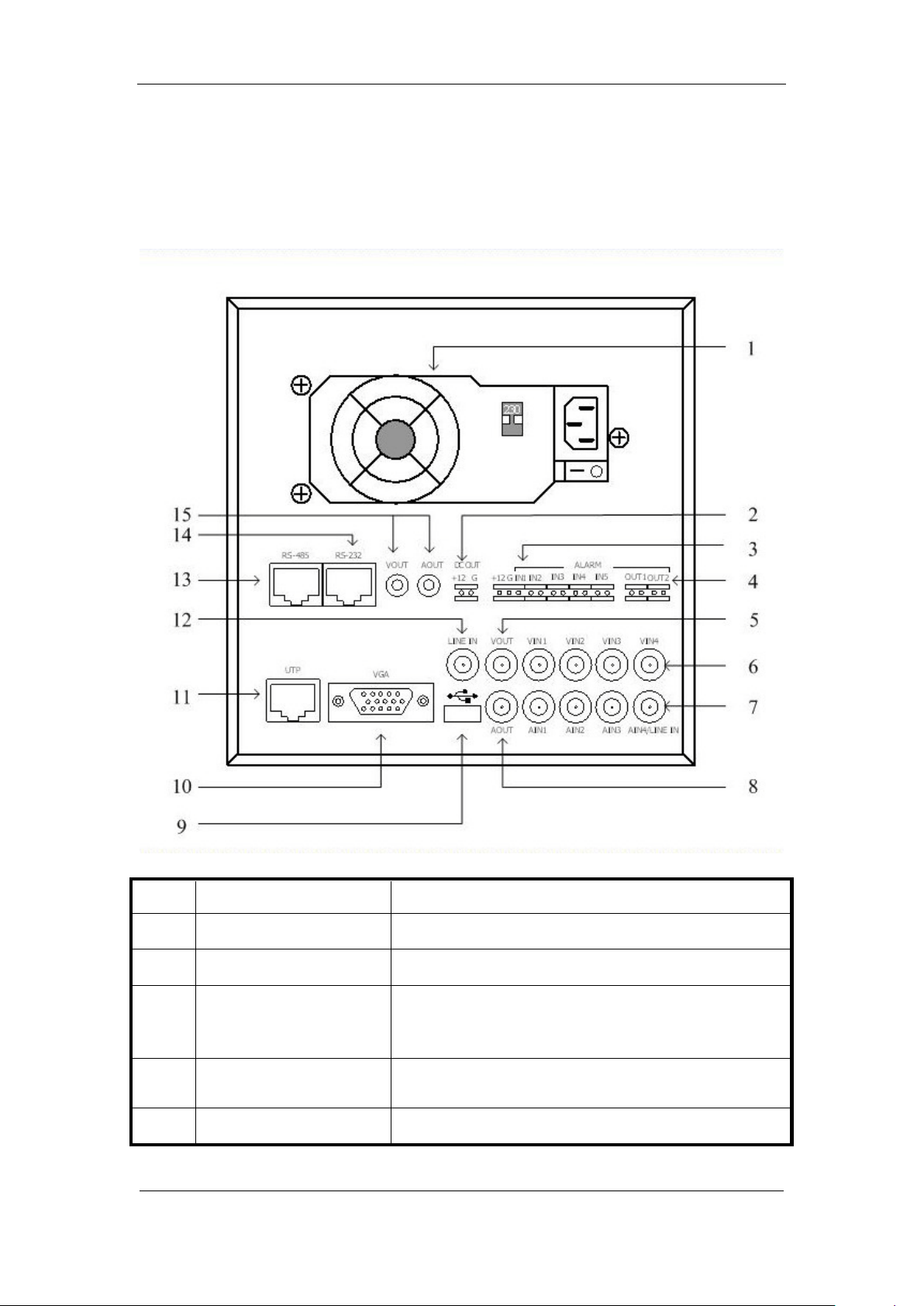
2.3 Rear Panel Description
Notice: Please refer to real product for different model.
Take DS-8004AHL-S for example:
Index Physical Interface Description
1
Power Adapter
2
Power Output
3
External Alarm In
4
Alarm Output
5
VOUT
ATX Standard. 220V or 110V option.
DC Output +12V/1A for camera.
Pin1 of Alarm
is GND; Pin3 is used to connect approaching sensor.
AlarmIn2, In3, In4 and In5 are switch trip.
Out1: Pin1 provides DC +12V/1A output; Pin2 is GND.
Out2: Relay output (switch trip).
Local video output, BNC interface.
Page 9 Total 116
Page 10

DS-8000AHI/AHLI/AHFLI-S Embedded Net DVR
6
7
8
9
10
11
12
13
14
15
VIN
AIN
AOUT
USB Interface
VGA Interface
UTP Network Interface
Line In
RS-485
RS-232
Output for Backup
4 video input, BNC interface.
4 audio input, BNC interface. The 4th audio input is also
used as Line in for voice talk.
Audio output, BNC interface
Connecting USB memory disk, USB HDD, USB CD-R/W
Connecting VGA display .
Connecting network devices. Refer to Appendix B for pin
definition.
Use 4th audio input instead.
PTZ connection. Refer to Appendix B for pin definition.
Connecting RS-232 devices. Refer to Appendix B for pin
definition.
Connecting analog recording device for backup.
Page 10 Total 116
Page 11
DS-8000AHI/AHLI/AHFLI-S Embedded Net DVR
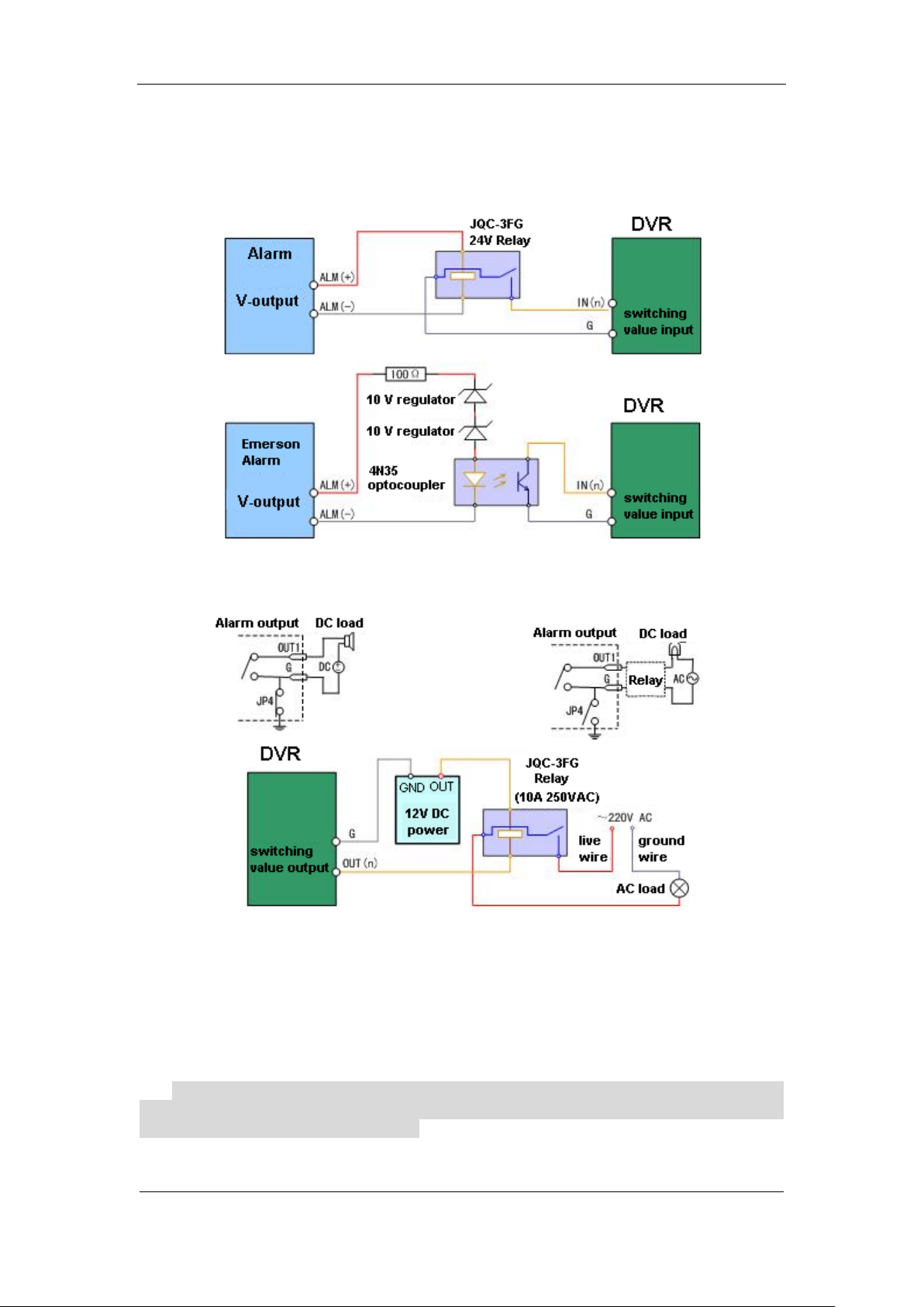
2.4 Connecting to alarm in/out device
The alarm input is switch signal,if the alarm input is not switch signal, such as voltage signal,
then please follow the connection method below.
If alarm output interfaces are connect to DC/AC load, then please refer the suggestion below.
Please pay attention to the different application of JP4 in these applications. If the interface is
connected with DV load, JP4 can be used in these two methods safely, and suggest that this should
be used within the limit of 12V/1A. if the interface is connect with AC load, then JP4 should be
cut off, unplug the short circuit object. Please use external relay for safety. (as shown in the figure)
There are 4 short circuit objects in the mother board, every alarm output interface correspond
one of them, and they are JP4, JP5, JP6 and JP7. It is short circuited after the DVR is produced, so
these short circuit objects should be unplugged when AC load is connected.
Attention! If the alarm output interface is used for control the AC circuit, short circuit
objects on mother should be unplugged, and external relay is needed to make sure the safety
of device, and prevent electric shock.
Page 11 Total 116
Page 12

DS-8000AHI/AHLI/AHFLI-S Embedded Net DVR
Illustration of cable connection
Device supplies the curved needle plug for signal cable connection, here is the process:
1、unplug the green Curved needle plug in the ALARM IN and ALARM OUT interface;
2、un-fasten the screws in the curved needle plug, then put the signal cable into little metal
box and then fasten the screws.
3、connect these curved needle plugs with the interface.
Page 12 Total 116
Page 13
DS-8000AHI/AHLI/AHFLI-S Embedded Net DVR
network transmission; Orange means recording and network
Chapter3 Operational Instructions
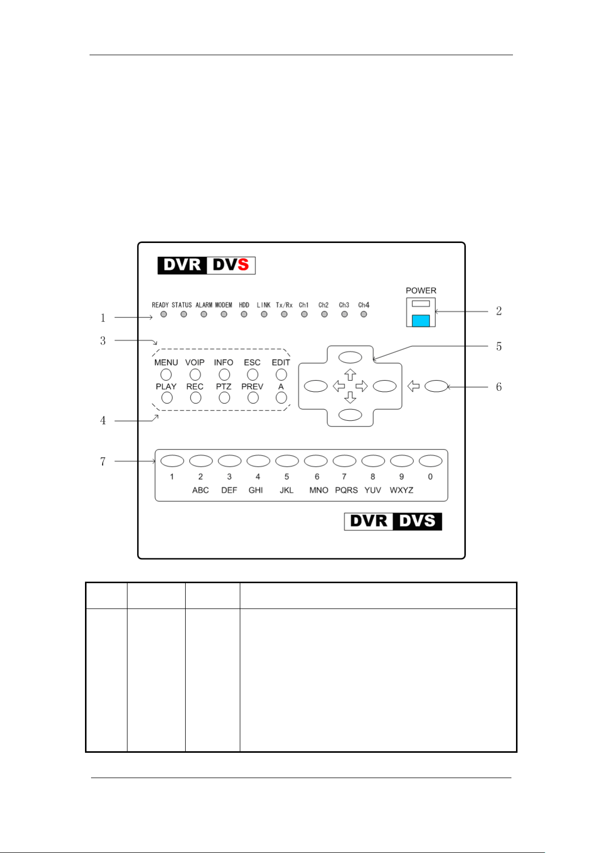
3.1 Front Panel
3.1.1 DS-8000AHI-S Front Panel
Index Type Name Description
1 Status
Lamps
READY
STATUS
ALARM
MODEM
HDD
LINK
Tx/Rx
CH1
DVR is ready.
Green means you can use IR remote control.
Red means there is alarm.
Green means modem connection and dial-up successful.
Twinkle in red means reading or writing HDD.
Green means network is OK.
Twinkle in green means data is being transmitted
Channel1 working status. Green means recording; Red means
Page 13 Total 116
Page 14

DS-8000AHI/AHLI/AHFLI-S Embedded Net DVR
network transmission; Orange means recording and network
network transmission; Orange means recording and network
network transmission; Orange means recording and network
Press [MENU] for more than 5 seconds to cancel button
Input switch (number, lower case, upper case and
CH2
transmission.
Channel2 working status. Green means recording; Red means
CH3
transmission.
Channel3 working status. Green means recording; Red means
CH4
transmission.
Channel4 working status. Green means recording; Red means
transmission.
2 POWER POWER Device switch with power indicator lamp. Green means DVR
is working; Red means DVR is powered off; No light means
no power is supplied.
3 Function
Keys
4 Shortcut
Keys
MENU
VOIP
INFO
ESC
EDIT
PLAY
REC
PTZ
PREV
A
1. Switch preview mode into menu;
2. Brush control short key【WIPER】.
3.
beep sound.
【ZOOM-】in PTZ control.
【ZOOM+】in PTZ control.
Cancel and back to parent menu.
1. In edit state, delete the current cursor character;
2. 【IRIS+】in PTZ control;
3. Select or × to enable or disable.
1. Local playback;
2. 【AUTO】in PTZ control.
1. Manual record;
2. 【SHOT】in PTZ control (adjust preset).
1. Enter into PTZ control mode;
2. 【IRIS-】in PTZ control.
1. Multi screen preview switch;
2. Switch menu mode into preview;
3. 【FOCUS-】in PTZ control.
1.
2. 【FOCUS+】in PTZ control;
3. In preview mode, display or hid e the ch an nel status bar .
5 Control
Keys
Direction
Keys
Composed of 【】,【】,【】 and 【】.
1. Menu mode, use【】/【】 to select,【】/【】 to
edit;
2. PTZ direction control;
3. Playback speed control.
6 Control
Keys
ENTER 1. Menu confirmation;
2. Select or × to enable or disable;
symbol);
Page 14 Total 116
Page 15
DS-8000AHI/AHLI/AHFLI-S Embedded Net DVR
means DVR is powered off. No light means no power is
The lamp is on means you can use compound keys as
3. Pause playback.
7 Input Keys Numeric
Keys
Input number, lower cas e, u pper case character and symbols.
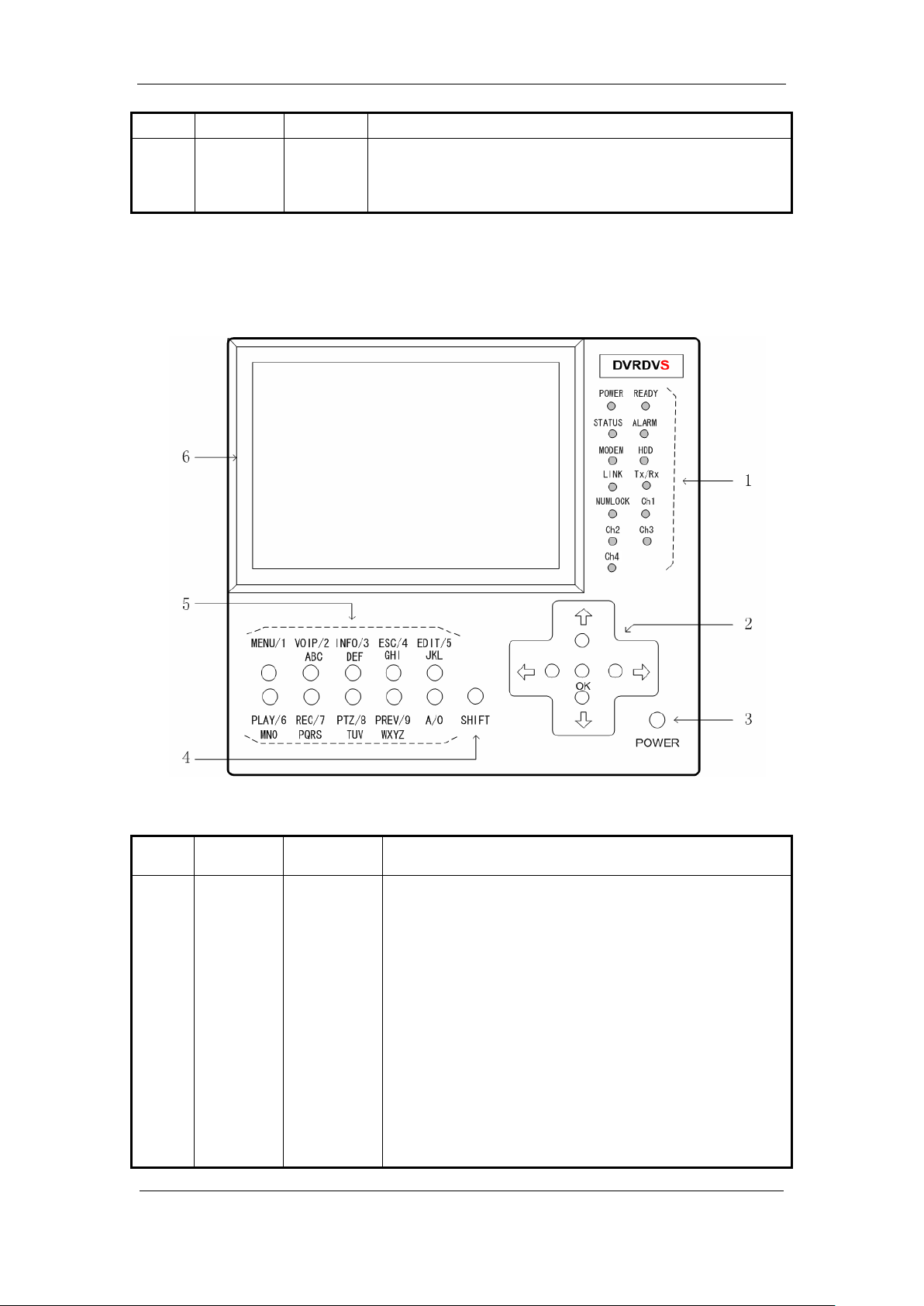
3.1.2 DS-8000AHLI/AHFLI-S Front Panel
Index Type Name Description
1 Status
Lamps
POWER
READY
STATUS
ALARM
MODEM
HDD
LINK
Tx/Rx
NUMLOCK
Power indicator lamp. Green means DVR is working; Red
supplied.
DVR is ready.
Green means you can use IR remote control.
Red means there is alarm.
Green means modem connection and dial-up successful.
Twinkle in red means reading or writing HDD.
Green means network is OK.
Twinkle in green means data is being transmitted
numeric keys to input numeral or English characters. The
Page 15 Total 116
Page 16

DS-8000AHI/AHLI/AHFLI-S Embedded Net DVR
lamp is off means the compound keys can be used as
Channel1 working status. Green means recording; Red
means network transmission; Orange means recording and
Channel2 working status. Green means recording; Red
Channel3 working status. Green means recording; Red
means network transmission; Orange means recording and
Channel4 working status. Green means recording; Red
function keys. You can use【SHIFT】key to switch.
CH1
network transmission.
CH2
means network transmission; Orange means recording and
network transmission.
CH3
network transmission.
CH4
means network transmission; Orange means recording and
network transmission.
2 Control
Keys
Direction
Keys
Composed of 【】,【】,【】 and 【】.
1. Menu mode, use【】/【】 to select,【】/【】
ENTER
2. PTZ direction control;
3. Playback speed control.
1. Menu confirmation;
2. Select or × to enable or disable;
3. Pause playback.
3 POWER POWER Power switch.
4 Switch
Key
5 Compound
Keys
6 LCD Display For local display.
Note: Please refer to DS-8000AHI-S about the compound keys functions.
SHIFT Switch between function keys and numeric keys. The lamp
of NUMLOCK will display the status.
MENU/1
VOIP/2
INFO/3
ESC/4
EDIT/5
PLAY/6
REC/7
PAN/8
PREV/9
A/0
Composite of【MENU】and【1】.
Composite of【VOIP】,【2】and【ABC】.
Composite of【INFO】,【3】and【DEF】.
Composite of【ESC】,【4】and【GHI】.
Composite of【EDIT】,【5】and【JKL】.
Composite of【PLAY】,【6】and【MNO】.
Composite of【REC】,【7】and【PQRS】.
Composite of【PAN】,【8】and【TUV】.
Composite of【PREV】,【9】and【WXYZ】.
Composite of【A】and【0】.
Examples of compound keys’ usage:
Used as function keys:
If the lamp of NUMLOCK is off, the compounds keys can be used as function keys. They are
defined as【MENU】, 【VOIP】, 【INFO】, 【ESC】, 【EDIT】, 【PLAY】, 【REC】, 【PAN】,
to edit;
Page 16 Total 116
Page 17
DS-8000AHI/AHLI/AHFLI-S Embedded Net DVR
【PREV】and【A】. Press【SHIFT】key to turn off NUMLOCK lamp when the lamp is on.
Used as numeric keys:
Press【SHIFT】to turn on NUMLOCK lamp when the lamp is off. In “Preview” and “PTZ
control” mode, the compound keys can be used as numeric keys to select channel. In “Edit” mode,
only in “Number” and “Symbol” input status (as following), you can use compound keys as
numeric keys.
You can use【SHIFT】to make compund keys int o fun ction key, and press function key【A】
to change the input status. Then you press【SHIFT】back to mumeric keys.
Used as character keys:
Press【SHIFT】key to turn off NUMLOCK lamp.
Press function key【EDIT】to enter into “Edit” mode.
Press【A】to select “Uppercase” or “Lowcase” input option.
Press【SHIFT】key to turn on NUMLOCK lamp, the compound keys can be used as character
keys.
Page 17 Total 116
Page 18
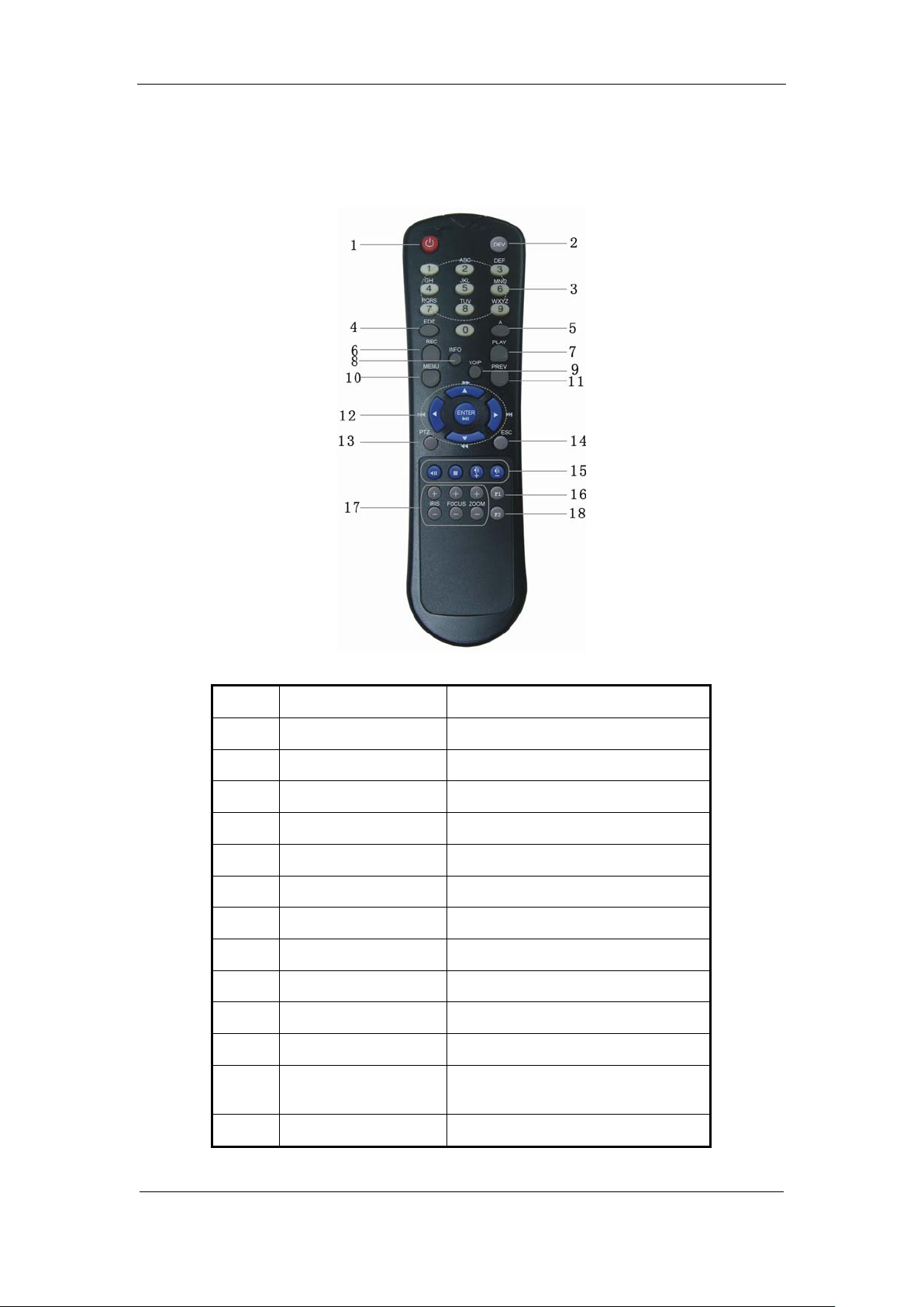
3.2 IR Controller
DS-8000AHI/AHLI/AHFLI-S Embedded Net DVR
Index Name Description
1 POWER Turn of f device.
2 DEV Enable/Disable IR remote control
3 Numeric Keys Same as numeric keys of front panel.
4 EDIT Same as EDIT key of front panel.
5 A Same as A key of front panel.
6 REC Same as REC key of front panel.
7 PLAY Same as PLAY key of front panel.
8 INFO Same as INFO key of front panel.
9 VOIP Same as VOIP key of front panel.
10 MENU Same as MENU key of front panel.
11 PREV Same as PREV key of front panel.
12
Direction Keys
ENTER
Same as direction keys and enter key
of front panel.
13 PTZ Same PTZ key of front panel.
Page 18 Total 116
Page 19

DS-8000AHI/AHLI/AHFLI-S Embedded Net DVR
IRIS, FOCUS ZOOM for camera
14 ESC Same as ESC key of front panel.
15 Reserved
16 F1 Same as【F1】key of front panel.
17 Camera control
control.
18 F2 Same as【F2】key of front panel.
Loading the batteries into the IR controller
1. Remove the battery cover.
2. Insert the battery. Please take care that the poles (+ and -) are correctly positioned.
3. Replace the battery cover.
Start to use IR controller
Press【DEV】key, input the DVR device ID (default is “88”, can be changed in “Display”
menu) and then press【ENTER】key. If the “STATUS” lamp of DVR front panel is turned into
green, it means you can use IR controller to operate this DVR.
Stop using IR controller
When IR controller status is on, press【DEV】key again, the “STATUS” lamp will be turned
off. The IR controller can no t control this DVR.
Switch the DVR off
When IR controller status is on, press【POWER】key for several seconds, the DVR will be
powered off.
When IR controller can not work normally
Check batteries poles.
Check the remaining charge in the batteries.
Check IR controller sensor is mask.
Please change another IR controller to try again. It the problem is still existed, please contact
administrator.
Page 19 Total 116
Page 20

DS-8000AHI/AHLI/AHFLI-S Embedded Net DVR
Adjust Brightness, Contrast, Hue
OSD Display mode, position and
ty, area
Resolution and recording
3.3 Menu Description
3.3.1 Menu Items
Menu Name Function Menu Name Function
Display
Recording
Alarms
PTZ
Preview
Unit name
Device ID
Require password
Screen saver
Video standard
Enable Scaler
Brightness
Menu transparency
VGA resolution
DST Setup
Date and Time
Overwrite/Stop recording
SATA1 DISK
Record Para
parameters setup
Record schedule
Enalbe EventPara
PreRecord time
PostRecord time
Alarm input type (Normal open/
Normal close)
Alarm response and PTZ linkage
Alarm output and schedule
PTZ parameters
Preset setup
Sequence setup
Cruise setup
Preview mode
Switch time
Enable/Disable audio preview
Display delay
Preview layout
Image
Network
Exceptions
RS232
User
Password
Camera name and position setup
and Saturation
OSD format setup
Mask area setup
View tampering area and response
setup
V ideo si gn al l oss
Motion detection sensitivi
and response setup
NIC Type,
IP, Mac & Port
Advanced setup,
DNS IP, Mask& Gateway
Multicast IP
Remote host IP & Port
NAS Setting
httpPort, PPPoE
E-mail Setup
Exceptions type
Exceptions response
RS232 parameters
RS232 work mode
Add or delete user
Password setup or modification
User rights setup
Page 20 Total 116
Page 21
DS-8000AHI/AHLI/AHFLI-S Embedded Net DVR
Restore parameters
Upgrade firmware
Transaction
Text input mode
ATM IP address
ATM type
Text information
Utilities
HDD management
Clear alarm output
Reboot
Power off
View log
System information
3.3.2 Menu Operation
How to enter into menu mode
Press【MENU】key to enter into DVR main menu.
Press【PLAY】short key to enter into playback menu.
Perss【REC】short key to enter into manual record menu.
Perss【PTZ】short key to enter into PTZ control interface.
Notes: You must input user name and password. The default user name is “admin” and
password is “12345”.
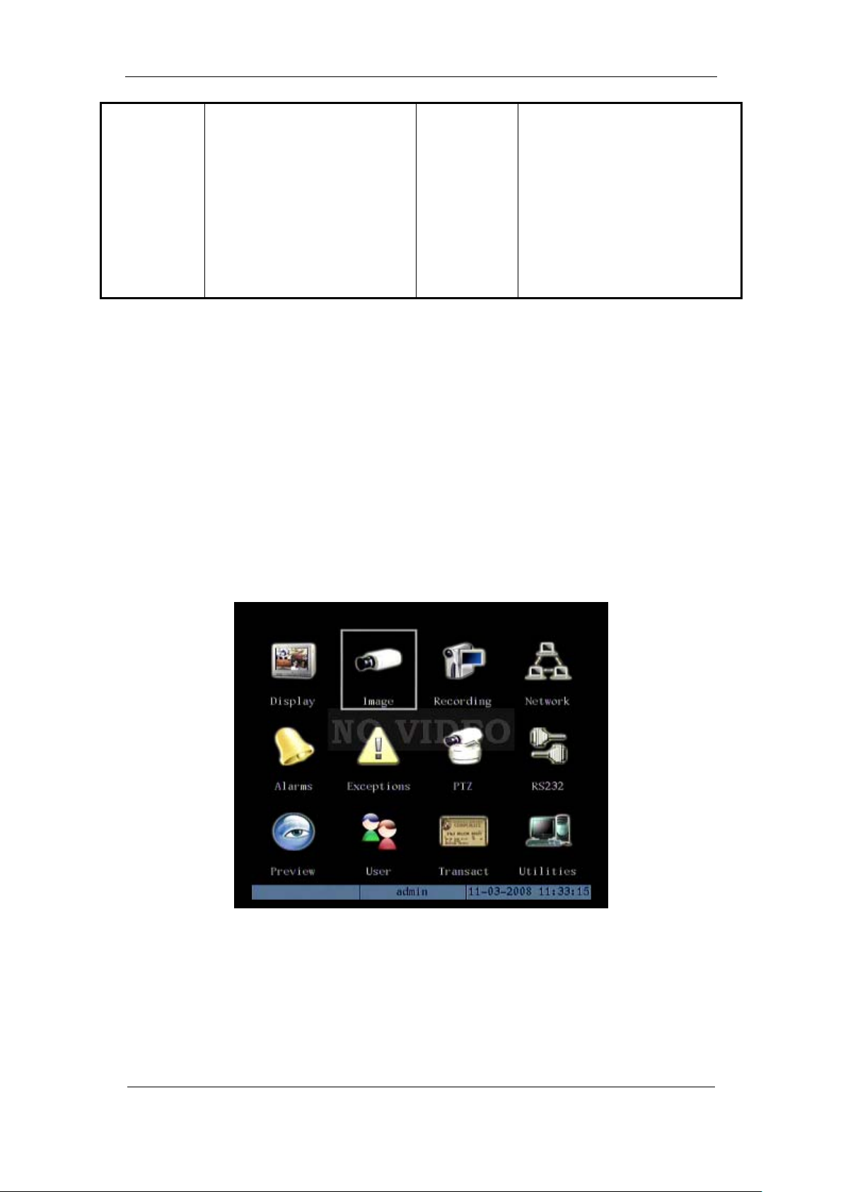
Main Menu Description
The main menu interface is following:
There is one small rectanglar frame named “Active Frame”. It can be moved from one icon to
another by using 【】or【】key. When the “Active Frame” is located on one icon, you can press
【ENTER】key to enter into the secondary menu. For example, move the “Active Frame” to
“Image” icon, press 【ENTER】to enter into the secondary menu as following:
Page 21 Total 116
Page 22
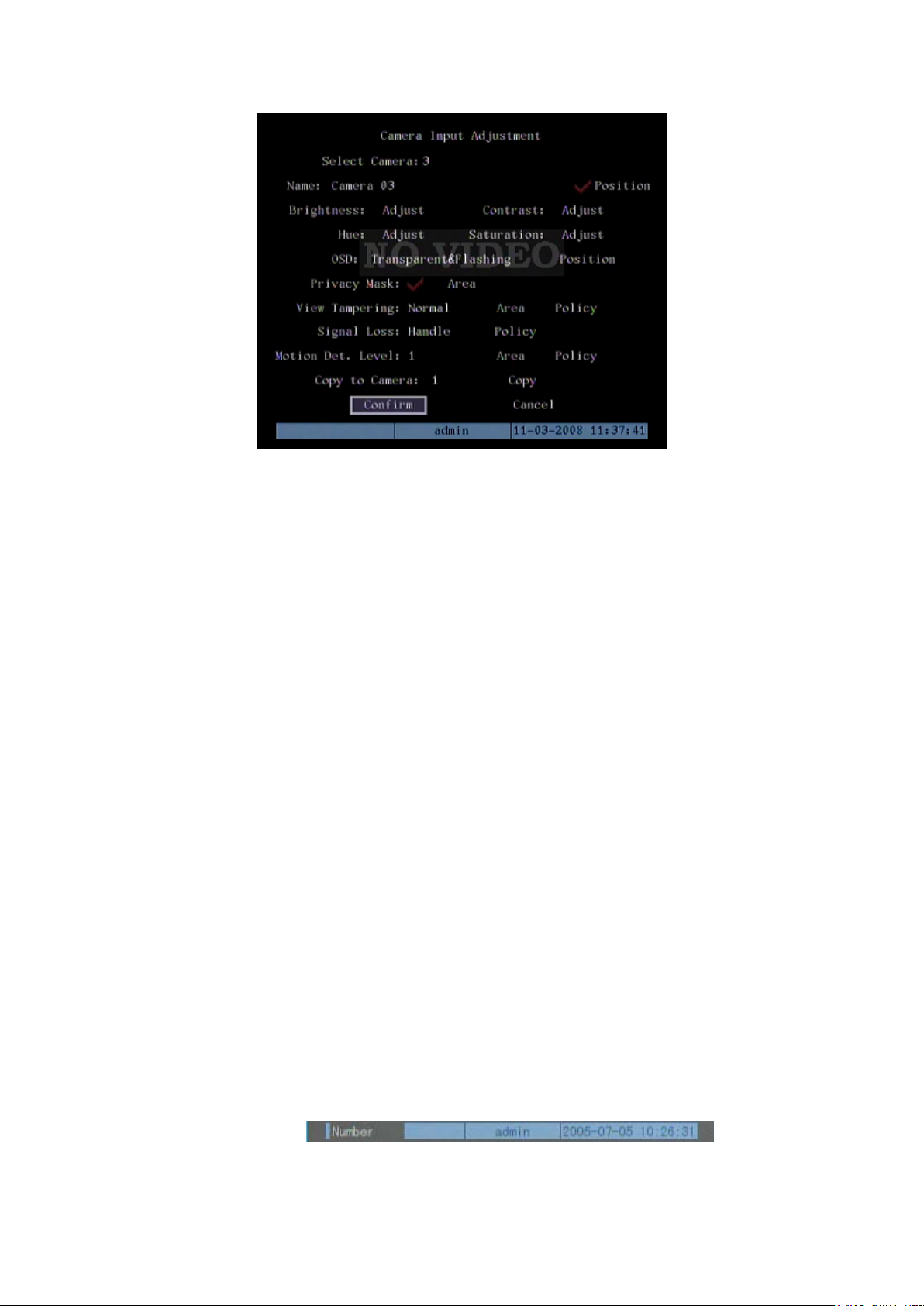
DS-8000AHI/AHLI/AHFLI-S Embedded Net DVR
Each menu contains different kinds of items. There is a small rectangular frame named
“Active Frame” which is pointing to the selected item. This “Active Frame” can be moved by
【】or【】keys. There are such kinds of menu items:
1. Check Box: Provide 2 options, “” means enable and “×” means disable. You can use
【ENTER】or【EDIT】key to switch over.
2. List Box: Provide more than 2 options. However, only one of them can be selected. You
can use【↑】and【↓】to select one option. For example, on the right side of “Select
Camera”, there is a list box for you to select one camera.
3. Edit Box: This is for you to input characters. Press【EDIT】key to enter into edit status,
you can input characters as following:
a) Press【A】key to select number, upper case, lower case or symbols;
b) Use【】and【】keys to move cursor;
c) Use【EDIT】key to delete the charcter in front of cursor;
d) Press【ENTER】or【ESC】to exit edit.
4. Button: Excute a special function or enter into next sub-menu. For example, press
“Policy” button to enter into sub-menu. Press【Confirm】to save parameters and return
to parent menu. Press【Cancel】button to cancel and return to parent menu. The button in
grey means it can be operated only after it is enabled.
How to exit menu
Press【PREV】key to exit menu and return to preview mode.
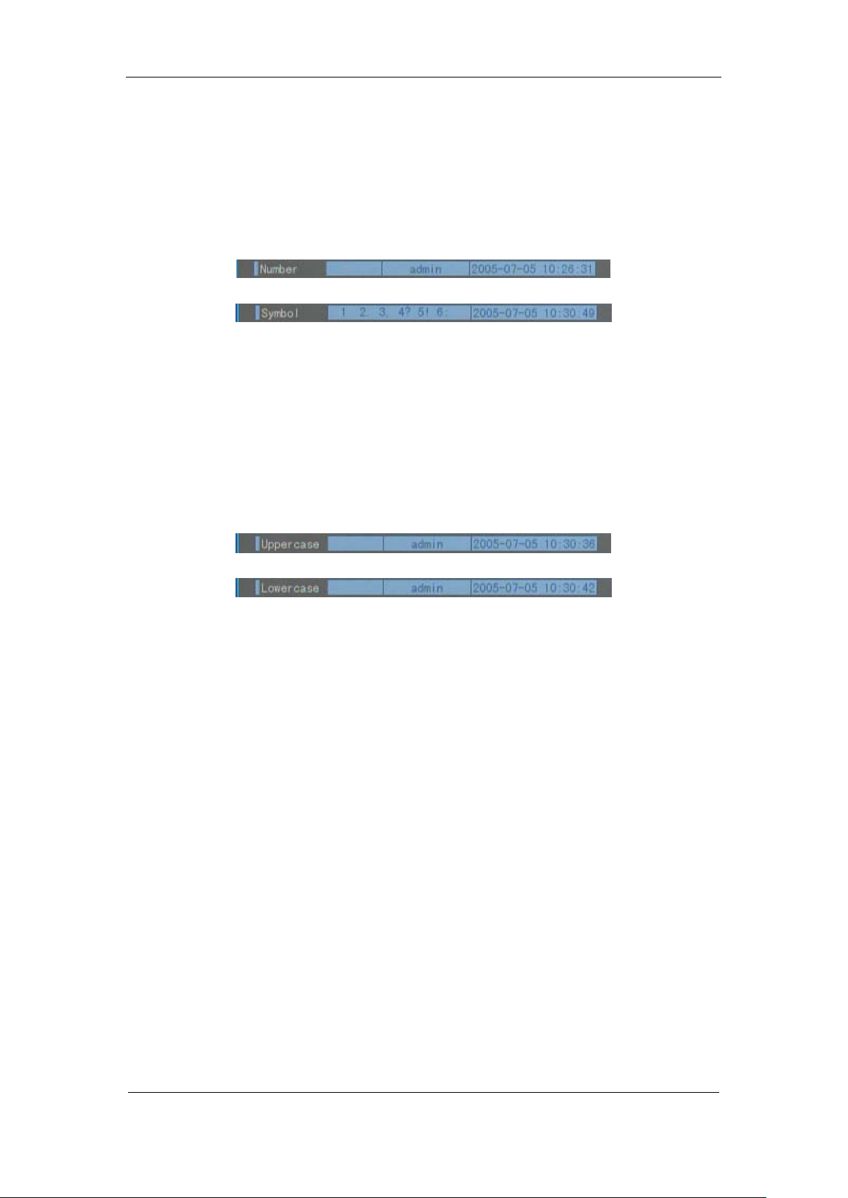
3.4 Character Input
In the menu interface, if you enter into edit status (for example, in the “camera name” edit
box), at the bottom of screen, the input status is appeared:
Here it means you can press numeric keys to input digital number.
Page 22 Total 116
Page 23

DS-8000AHI/AHLI/AHFLI-S Embedded Net DVR
Press【A】key to change input methods. You can select “number”, “Uppercase”, “Lowercase”
or “Symbol”.
Uppercase
Lowercase
Symbol
There are 24 symbols in all. They are divided into 4 pages, and you can use【0】key to turn over
page.
If you want to input English character, for example, 【ABC】 key, in the uppercase or
lowercase mode, press the button one time, you can input “A” or “a”; press the button two times
continuously, you can input “B” or “b”; press the button three times con tinuously, you can input
“C” or “c”. It is the same usage for other characters.
Please note: for DS-8000AHLI-S & DS-8000AHFLI-S, you can press【SHIFT】button to
switch between function keys and numeric keys.
Page 23 Total 116
Page 24

DS-8000AHI/AHLI/AHFLI-S Embedded Net DVR
Chapter4 Basic Operation Guide
4.1 Power on
Note: Please make sure the power supply matches DVR and AC cable connected
correctly. Before switch DVR on, please connect one monitor with VOUT or VGA interface.
Otherwise, you can not see graphic user interface and can not operate.
If【POWER】lamp is off, please do as following:
Step1: Connect AC cable correctly;
Step2: Switch on the power button on the real panel.
If【POWER】lamp is in red, just press【POWER】button to start DVR.
When DVR is started,【POWER】lamp is in green. On the monitor or VGA display, DSP and
HDD initialization process will be shown.
The first line represents DSP initialization. If the DSP icon is “×”, it means that the DSP is
initialized error, please contact administrator at once.
The second line represents HDD initialization. Icons of SATA1 master and slaver HDDs,
SATA2 master and slaver HDDs, etc are displayed. If the HDD icon is “×”, it means the
corresponding HDD is not installed or not detected. If HDD is not detected, please contact
administrator.
Note: If HDD is not installed or not detected, DVR will beep for alarm. You can disable the
alarm option in “Exceptions” menu.
4.2 Preview
DVR will enter into preview mode after it is started.
On preview screen, you can see date, time, camera name and camera status icon.
Set system date and time in “Display” menu, referring to 5.2.9; Change camera name in
“Image” menu, referring to 5.3.2.
In the screen, it will display record and alarm status of each camera. These two kinds of
status will switch over automatically.
Press【A】key to display or hide the camera status bar.
Page 24 Total 116
Page 25

DS-8000AHI/AHLI/AHFLI-S Embedded Net DVR
Camera record status is following:
Icon Icon Color Status Description
White No video signal
Yellow Vdieo input
Pink Manual recording
Green Real time recording
Blue Motion detect recording
Red External alarm recording
Page 25 Total 116
Page 26

DS-8000AHI/AHLI/AHFLI-S Embedded Net DVR
Camera alarm status is following:
Icon Icon Color Status Description
White Video signal lost
Yellow V iew tam per ing alar m
Pink Motion&External alarm
Green No alarm
Blue Motion alarm
Red External alarm
Press numeric keys to switch over individual camera preview.
Press【EDIT】key to manual cycle preview. You can set the auto preview mode in “Preview”
menu, referring to 5.11.
Press【PREV】key to switch multi-screen perview.
Page 26 Total 116
Page 27

DS-8000AHI/AHLI/AHFLI-S Embedded Net DVR
4.3 User name and password
Note: When DVR is delivered from factory, there is only one default administrator
named “admin”, and password is “12345”. The administrator’s name can not be modified,
while the password can be modified. The administrato r can create 15 users and define their
user rights.
Login
Login dialog is following:
Use【】/【】keys to select one user, perss【】key to enter into “Password” edit box, input
corresponding password, press【ENTER】key to exit edit box. The “Active Frame” will be moved
to “Confirm” button. Press【ENTER】key to enter into main menu. If there is beeper alarm, it
means the user name and password are not matched. After three error times, DVR will enter into
preview mdoe.
Modify password
For those users created by admin, they can modify their password as following:
Step1: Enter into main menu
Press【MENU】key, in the login dialog, select your user name, input the correct password, you
can enter into the main menu.
Page 27 Total 116
Page 28

DS-8000AHI/AHLI/AHFLI-S Embedded Net DVR
Setp 2: Enter into password modification menu
Move the “Active Frame” to “Password” icon by using【】/【】keys. Press【ENTER】
key to enter into following password menu:
Step 3: Input new password
Press【EDIT】key to enter into edit box. You can use numeric keys to input new password.
The password can be null. It also can be 16 numerals. Press【ENTER】to exit edit box, and move to
“Verify” item to input the ve r if y password.
Note: In edit box, use 【】/【】to move cursor and【EDIT】key to delete the numeral
in front of the cursor.
Step 4: Modify password successfully
Move the “Active Frame” to “Confirm” button, press【ENTER】key. If the password is
modified successfully, you will get the main menu. Or an error dialog will be pop up. You can
repeat step 3 to modify again.
Page 28 Total 116
Page 29

DS-8000AHI/AHLI/AHFLI-S Embedded Net DVR
4.4 PTZ Control
Note: The user must have the “PTZ control” right.
PTZ control interface
In preview mode, press【PTZ】key, in the login dialog, select one user name and input the
correct password, you can enter into PTZ control interface.
In menu mode, press【PTZ】key, you can enter into PTZ control interface directly.
There is “PTZ Control” prompt in the PTZ control interface. The displayed camera name
means which channel’s PTZ is under control. For example, “Camera 01” means you are
st
controlling the 1
camera PTZ.
Select channel
In PTZ control mode, you can press numeric keys to select channel.
After you select the camera PTZ, you can use the shortcut keys to control PTZ.
PTZ control keys description
Direction control keys: 【↑】,【↓】,【←】,【→】;
ZOOM control keys: 【ZOOM+】,【ZOOM-】;
FOCUS control keys: 【FOCUS+】,【FOCUS-】;
IRIS control keys: 【IRIS+】,【IRIS-】;
Adjust preset keys: 【REC/SHOT】;
Auto control key: 【PLAY/AUTO】;
Wiper control key : 【WIPER/MENU】;
Light control key: 【LIGHT/F1】;
Auxiliary device control key:【AUX/F2】
Page 29 Total 116
Page 30

DS-8000AHI/AHLI/AHFLI-S Embedded Net DVR
Adjust preset description
In PTZ control mode, press【REC/SHOT】key, and press the preset number (three numeric
keys), DVR will adjust the corresponding preset number. Repeat pressing【REC/SHOT】key, and
press the preset number, DVR will adjust that preset number.
When you exit PTZ control mode, the camera will stay at the current position.
Note: The PTZ preset number is set already. Please refer to PTZ menu for preset setup. V1.4
firmware can support 128 preset numbers at most.
Start/Stop auto in PTZ control mode
In PTZ control mode, press【 PLAY/AUTO】 key to start PTZ auto function. Press
【PLAY/AUTO】key again to stop.
When PTZ is in auto mode, if you exit PTZ control mode, PTZ will continue auto
function.You must enter into PTZ control mode again, and press【PLAY/AUTO】ke y to stop.
Exit PTZ contrl mode
Press【ESC】or【ENTER】to exit and return preview mode.
Page 30 Total 116
Page 31

DS-8000AHI/AHLI/AHFLI-S Embedded Net DVR
4.5 Manual Record
Note: The user must have the corresponding right, DVR has HDD and HDD is formatted
already.
Manual record
In preview mode, press【REC】key, in the pop-up login dialog, select the name and input the
correct password, you can enter into the “Manual Record” interface.
In menu mode, press【REC】key to enter into “Manual Record” interface directly.
Description
Manual record interface has following parts: channel number, channel status, start/stop record,
start all and stop all buttons.
Channel: List the channel number that DVR has.
Status: Channel work status has 4 cases:
recording (including real time recording, alarm recording, motion detection recording). Red means
network tramsmission. Orange means both recording and network transmission.
Start/Stop: ““ means you can start corresponding channl recording. “×” menas you can
stop recording.
Start All: Press this button to start all channels recording.
Stop All: Press this button to stop all channel recording.
Exit manual record
Press【ESC】key to enter into preview mode. Press【MENU】key to enter into main menu.
Press【PLAY】key to enter into playback menu. Press【PTZ】key to enter into PTZ control mode.
means idle. Green means the channel is
Page 31 Total 116
Page 32

DS-8000AHI/AHLI/AHFLI-S Embedded Net DVR
4.6 Playback
Note: The user msut have “Playback” right.
Playback interface
In preview mode, press【PLAY】key, in the pop-up login dialog, select username and input
correct password, you can enter into “Playback” interface.
In menu mode, press【PLAY】key, you can enter into “Playback” interface directly.
One Channel Playback
Two Channels Playback
Description
If DVR only supports one channel playback, you can not select second channel. If DVR can
support two channels playback, you can select second channel.
Page 32 Total 116
Page 33

DS-8000AHI/AHLI/AHFLI-S Embedded Net DVR
Main Channel: Use【↑】or【↓】key to select one channel.
Second: If DVR support 2-ch playback, you can use【↑】or【↓】key to select the second
channel except the main channel. These two channels can be playback synchronously. If you
select the second channel as none, only the main channel is playback.
Rec Type: Use【↑】or【↓】to select recorded files type. The file type options have “All”, “All
Time”, “Motion Detect”, “Alarm” and “Manual”.
Time Section: You can define the search time section. Move “Active Frame” to the time edit
box, use numeric keys to input the detail time.
Card Number: DVR can get text number through RS-232 or network port. The text is sent
from devices such as ATM machine, POS machine or others. DVR can overlay the text on the real
time image and record. You can use the text to search the recorded files and playback them. Use
the numeric keys to input the text number.
Search: Search the matched reorded files and display them in the list box. If there is not
matched file, a corresponding dialog box will be pop-up.
Play by Time: Playback the recorded stream directly based on the time section.
Select Page: In the file list box, each page will only display 8 files. If the matched files are
more than 8, you can select page to list other files. 500 pages (4000 files) can be searched in one
time. You can use numeric keys or 【↑】【 ↓】keys to select page.
File List Box: List the matched files. File started time, file size are displayed in the list
box.You can use【↑】【 ↓】keys to move the scroll bar to select file.
Backup Devices: You can select USB flash, USB HDD, USB CD-R/W to backup the files or
clips.
Copy: Start to backup.
Backup T oday: Backup all recorde d fi les of today.
Three kinds of playback mode
1. Search and playbck file: In the playback interface, you can select main channel, second
channel (2-ch palyback), record type, time section. Move “Active Frame” to “Search” button and
press【ENTER】key, DVR will search and list the matched files.
Page 33 Total 116
Page 34

DS-8000AHI/AHLI/AHFLI-S Embedded Net DVR
If the matched files are more than 8, you can use “Page No.” to select page (use numeric keys
or【↑】【 ↓】keys to select page). In the file list box, use【↑】【 ↓】keys to move the scroll bar to th e
file, press【ENTER】key to playback the file. If the second channel is selected, these two channels
can be playbak synchronously.
If DVR can not find the matched files, an error prompt will pop-up.
2. Playback by Time: In the playback interface, select main channel, second channel (2-ch
playback), record type and time section, move “Active Frame” to “Play” button, press【ENTER】
key , DVR will start to playback based on time section.
3. Search by Card No and Playback file: In the playback interface, select main channel,
second channel (2-ch playback), record type, enable card No. search option (““) and input the
card number, move “Active Frame” to “Search” button, press【ENTER】key, DVR will search and
list the matched files. If the matched files are more than 8, you can use numeric keys or【↑】【 ↓】
keys to select page. Use【↑】【 ↓】keys to move scroll bar to the file, press【ENTER】key to playback
the selected file. If DVR can not find the matched files, an error prom pt will pop-up.
Operation when playback
Playback picture:
Page 34 Total 116
Page 35

DS-8000AHI/AHLI/AHFLI-S Embedded Net DVR
One Channel Playback
Two Channels Playback
At the bottom of image, there is an information bar and the following information is included:
Volume, Play Progress, Play Speed, Played Time and File Total Time.
Display/Hide information bar: 【MENU】
Open/Close sound: 【PLAY】
Adjust play progress: 【←】(Backward),【→】(Forward). The unit is “%”.
Adjust play speed: Normal speed is “1x”. Use 【↑】to increase play speed ( 2X, 4X,
8X and MAX). Use【↓】to decrease play speed (1/2X, 1/4X, 1/8X and Frame by
Frame)
Pause/Continue: Press 【ENTER】to pause/continue playback. If played frame by
frame, Press【ENTER】to paly one frame.
Copy segment:【EDIT】
Exit: 【ESC】
Page 35 Total 116
Page 36

DS-8000AHI/AHLI/AHFLI-S Embedded Net DVR
Playback switch: When in 2-ch playback, press【PREV】to switch between main
channel and second channel.
Note: When DVR is busy, if you select high play speed, maybe there is difference for actual
play speed.
Exit playback
In playback interface, press【ESC】key to enter into preview mode.
In playback interface, press【MENU】key to enter into main menu, press【REC】key to enter
into manual record, and press【PTZ】key to enter into PTZ control mode.
Page 36 Total 116
Page 37

DS-8000AHI/AHLI/AHFLI-S Embedded Net DVR
4.7 Backup Recorded Files
Note: The user must have “Playback” right. Please connect with bac kup devices before
you start to backup.
In the playback interface, you can backup the recorded files.
In the preview mode, press【PLAY】key, in the login dialog, select username and input the
correct password, you can enter into the playback inter f ace.
In the menu mode, just press【PLAY】key, you can enter into playback interface directly.
Backup intraday recorded files
In the playback interface, move “Active Frame” to “Backup Today” button, press【ENTER】
key, all intraday recorded files of all channels will be backup to the save device. A pop-up dialog
will display the backup status.
If bakup device is not connected correctly or DVR do not detect the backup device, the
following dialog will be pop-up. Please ask administrator for more information.
Backup the files that matched your requirement
Step 1: Search the matched files
In the playback interface, select one channel and record type, input the time section, move
“Active Frame” to “Search” button, press【ENTER】key, DVR will start to find and list the
matched files.
Page 37 Total 116
Page 38

DS-8000AHI/AHLI/AHFLI-S Embedded Net DVR
Step 2: Select the files that you want to backup
In the file list box, use【↑】or【↓】keys to move the scroll bar. When the scroll bar stays at the
file you wan to backup, press【EDIT】key to select it. The symbol “” is the selection tag. You can
use the same method to select other files you want to backup. After finish, you can do next step.
Step 3: Select backup device
Please confirm the backup device: USB flash memory, USB HDD, USB CD-R/W and select
the corresponding backup device.
Step 4: Start and finish backup
Move “Active Frame” to “Save” button and press【ENTER】key to start backup.
When backup is started, corresponding message box will pop-up to indicate the result.
Backup video segment
You also can backup the image segments when the image is being playback. The steps are:
1) Enter into the interface of playback the files or playback by time;
2) Press【EDIT】key to start selecting the current playback image, and press【EDIT】again
to stop selecting. This segment is slected;
3) You can repeat step 2 to select many segments. 30 segments can be selected in all;
4) After you select all segments, press【ESC】key, a message window will pop-up. If you
press “Confirm” button, DVR will start to backup the selected segments. If you press
“Cancel” button, DVR will abort backup.
Note: The backup function is effective when two channels are playback synchronously. In
such case, each channel can backup 30 segments so 60 segments can be backup for two channels.
Auto Backup:
Page 38 Total 116
Page 39

Notes:
DS-8000AHI/AHLI/AHFLI-S Embedded Net DVR
a) SATA HDD for auto backup needs to be connected to the 1
st
SATA interface;
b) SATA HDD for auto backup needs to be formatted by selecting “format” in the auto backup
menu instead of in the HDD management menu.
1. First please enter “Recording” menu, select “Backup” for SATA1 Disk, then confirm and
restart the device to make the parameter become effective; shown as figure below:
2. Then you’ll find “Backup Today” turn to “Auto Backup” in the “Playback” interface; shown
as figure below:
Page 39 Total 116
Page 40

DS-8000AHI/AHLI/AHFLI-S Embedded Net DVR
3. Select “Auto Backup” and enter the submenu shown as below:
4. Enable the auto backup: Pressing “confirm” or “edit” button to enable(“”) or disable(“×”)
the function.
5. Select camera you want to auto backup by using
or button and enable(“”) it by
pressing “confirm” or “edit”.
6. Day Set: select how many days you want to auto backup, there are options:1,2,3,4,5,6,7.
7. Time set: select the time period (only available when select 1 day). You can just input the start
time and end time (hh:mm:ss).
8. Backup Delay: you can select time delay for auto backup by using
or button, there are
options: 0min, 10min, 20min, 30min,40,50,60,70,80,90.
9. Save the settings by pressing “Confirm” or you can cancel it if you want.
Playback the video segment
You can use our file player software to playback the video segment in PC. You can find the
player software in attached CD.
Exit playback interface
Please refer to chapter 4.6.
Page 40 Total 116
Page 41

DS-8000AHI/AHLI/AHFLI-S Embedded Net DVR
4.8 Voice Talk
【VOIP】is not available.
You can use client software to start talking with DVR.
4.9 Shut down DVR
Note: Do not switch off the power directly in case of damaging HDD. The correct step is
using “Power Off” in the “Utilities” menu, or【POWER】key on the front panel or on IR
controller.
Shut down DVR normally
Use menu
Enter into “Utilities” menu, move “Active Frame” to “Power Off” button and enter into
power off dialog, press “Confirm” to shut down the DVR.
Use【POWER】key of front panel or IR controller
Press【POWER】key for above 3 seconds.
In preview mode, a login dialog will pop-up, select user name and input password, press
【Enter】to enter into power off dialog and press “Confirm” to shut down DVR. If you input error
password for three times, DVR will return preview mode.
In menu mode, if the user has “Utilities” right, you can enter into power off dialog; press
“Confirm” to shut down DVR. Otherwise, the user can not shut down DVR.
If DVR is shut down correctly, the【POWER】lamp is in red.
Note: When message of “Shut down…” is appeared, please do not press【POWER】key any
Page 41 Total 116
Page 42

DS-8000AHI/AHLI/AHFLI-S Embedded Net DVR
more; otherwise, DVR can not be shut down.
Shut down DVR abnormally
Use the power switch of real panel
When DVR is run, if you switch off the power, the HDD in DVR will be damaged. Please
avoid such operation.
Take away the power cable
Please avoid taking away the power cable directly.
Note: In some cases, when the power supply is abnormal, DVR will be damaged. We suggest
you to use those stable power supplies.
Page 42 Total 116
Page 43

DS-8000AHI/AHLI/AHFLI-S Embedded Net DVR
Chapter5 Parameters Setup Guide
Only the users that have “Parameters Setup” right need read this chapter. When the following
parameters are modified and saved, you must reboot the DVR to make the new parameters take
into effective. Other parameters do not need to reboot.
Any network parameters
Bit rate type, resolution and record schedule
External alarm sensor type
View tampering alarm schedule
Video lost alarm schedule
Motion detection alarm schedule
External alarm schedule
Alarm output schedule
Transaction
5.1 Administrator and Password
When DVR is left from factory, there is one default administrator. The name is “admin” and
password is “12345”. The name can not be changed, while the password can be.
Password modification
Press【MENU】key, in the login dialog, select the username as “admin”, use【→】key, move
cursor to password edit box, input “12345”, press “Confirm” to enter into administrator menu.
Move “Active Frame” to “User” icon, press【ENTER】key to enter into “User Management”
menu.
Page 43 Total 116
Page 44

DS-8000AHI/AHLI/AHFLI-S Embedded Net DVR
In the user name list box, only “admin” is existed. You can use【→】key, move “Active
Frame” to password edit box, and press【EDIT】key to enter into edit status. Press numeric keys to
input the new password. The password is only combined by 16 numerals at most. After you finish
inputting password, press【ENTER】key to exit. Move “Active Frame” to “Verify password” edit
box, input the verify password. Move “Active Frame” to “Confirm” button, and press【ENTER】,
if password and verify password are the same, the password will be saved and taken into effective.
If password and verify password are not same, a warning message box will be appeared.
In this case, press【ENTER】to return password edit box, and input new password again.
Page 44 Total 116
Page 45

DS-8000AHI/AHLI/AHFLI-S Embedded Net DVR
5.2 Add and Delete User
Enter into “User Management” interface.
Add user
The steps are following:
Step 1: Enter into “User Management” menu
Please refer to chapter 5.1
Step 2: Add new user name
In the “User Management” menu, move “Active Frame” to “Add” button and press
【ENTER】, in the pop-up dialog, input the new user name (refer to chapter 3.4), press 【ENTER】
and return “User Management” menu. 15 users can be added in all.
Page 45 Total 116
Page 46

DS-8000AHI/AHLI/AHFLI-S Embedded Net DVR
Step 3: Setup the password for new user
After you add one new user, the password is null. You can skip this step if you do not want to
change the password.
In the users list box of “User Management” menu, use【】【 】keys to select the new user
name, then use【】key to the password edit box. Press【EDIT】key to enter into edit box, use
numeric keys to input the new password.
Step 3: Setup the rights for new user
The new added user has not any operational rights. You must setup rights for him.
In the users list box of “User Management” menu, use【】【 】keys to select the new user
name, then use【】key to “Default Rights” b utton, press【ENTER】, the user will have the default
rights. The default rights include local playback, remote playback and view log.
If you want to define the detail rights, move “Active Frame” to “Setup Rights” button and
press【ENTER】to enter into rights setu p menu as following:
Page 46 Total 116
Page 47

DS-8000AHI/AHLI/AHFLI-S Embedded Net DVR
Operational rights are divided into “Local Rights” and “Remote Rights”. You can assign the
necessary rights to the user. Use【】【 】key to move “Active Frame” to the corresponding right
items, press【ENTER】or【EDIT】key to enable or disable the i tem. “” means assigning the right
to that user .
After you finish, press “Enter” button, the user’s rights will be saved and return “User
Management” menu. If you press “Cancel” button, the user’s rights will be aborted.
Step 4: Save the new user’s password and rights
In the “User Management” menu, press “Confirm” button, the user’s password and rights
will be saved and return main menu. If you press “Cancel” button, the user’s password and rights
will be aborted.
User rights description
“Local Rights”:
Local rights are for local operation, such as the operation using front panel, IR controller and
RS-485 keyboard.
PTZ control: Locally control PTZ;
Record: Manual start/stop recording;
Playback: Local playback and backup the recorded files;
Parameters Setup: Locally setup the DVR parameters;
Log: Locally view the log on DVR ;
Utilities: Locally upgrade firmware, format HDD, reboot DVR and shut down DVR, etc.
“Remote Rights”:
PTZ Control: Remote control PTZ;
Record: Remote manual start/stop recording;
Playback: Remote playback, download the recorded files on DVR;
Parameters Setup: Remote setup the DVR parameters;
Log: Remote view the log on DVR;
Utilities: Remote upgrade firmware, format HDD, reboot DVR and shut down DVR, etc.
Voice: Client talks with DVR;
Preview: Network live preview;
Alarm: Remote control DVR alarm output;
Local Video Out: Remote control DVR video output;
Com Control: DVR RS-232 transparent channel function.
MAC address
This MAC address is not the address of DVR but the PC that will access DVR. If you setup
this MAC address, only the PC with this MA C addr es s can acc es s t hi s DV R.
At PC end, in DOS prompt, you can use “ipconfig” command to get the PC MAC address (6
bytes).
Page 47 Total 116
Page 48

DS-8000AHI/AHLI/AHFLI-S Embedded Net DVR
Delete user
In “User Management” interface, you can use【】【 】keys to select one user, then use【】,
move “Active Frame” to “Del” button, press【ENTER】, in the pop-up confirmation dialog, pr ess
“Confirm” button to delete the selected user and return. Press “Cancel” or【ESC】to abort deleting.
Page 48 Total 116
Page 49

DS-8000AHI/AHLI/AHFLI-S Embedded Net DVR
5.3 Unit Name and Device ID
Unit name
In the “Display” menu:
There is an item named “Unit Name”. The default unit name is “Embedded Net DVR”. Move
“Active Frame” to unit name edit box, press【EDIT】key to enter into edit status, you can modify
the unit name. About how to input characters, please refer to chapter 3.4. Press【ENTER】key to
finish modification. Select “Confirm” button and pres s【ENTER】, you can save the new unit name
and make it into effect. Press “Cancel” button or【ESC】key to abort modification.
Device ID:
When you use IR controller to operate DVR, you must use device ID to select DVR. The
default device ID of DVR is “88”. If there are more than one DVR in one place, please define
different device ID for each DVR. Otherwise, the IR controller will control all DVR with the same
device ID at the same time.
In “Display” menu, move “Active Frame” to the device ID edit box, in the edit status, you
can use numeric keys to input new device ID. The device ID value is ranged among 01-100.
After you finish the modification, press “Confirm” button to save and take effect or press
“Cancel” to abort modification .
Page 49 Total 116
Page 50

DS-8000AHI/AHLI/AHFLI-S Embedded Net DVR
5.4 Video Output Standard and VGA Setup
Video output standard
There is one VOUT BNC connector at the rear panel of DVR. It is used to connect with
analog monitor and can support PAL or NTSC video output. You can modify video output
standard to match video input.
In “Display” menu:
There is a list box named “Video Standard”, you can use【】【 】key to select PAL or NTSC
video output.
VGA setup
There is one VGA interface at the real panel of DVR. You can use it to connect with VGA
display. You can define VGA resolution; refresh frequency in “Display” menu.
There are following options: 1024*768/60Hz, 800*600/60Hz and 800*600/75Hz. You can
use【】【 】key to select.
Press “Confirm” button to save or “Cancel” to abort.
Page 50 Total 116
Page 51

DS-8000AHI/AHLI/AHFLI-S Embedded Net DVR
5.5 OSD Setup
OSD is abbreviation of “On Screen Display”. For our embedded DVRDVS, it includes
displaying system time and camera name.
OSD settings include: System time, time format, time display position, camera name, camera
name display position, etc.
System Time
In “Display” menu, you can setup DVR system date and time.
Display System Time
You can setup display properties for each camera, including display status, position and
format. Of course, you can copy the properties of one camera to all cameras.
In “Image Setup” menu as following, select one camera:
Page 51 Total 116
Page 52

DS-8000AHI/AHLI/AHFLI-S Embedded Net DVR
Display mode: There are several display modes: Opaque&Steady, Transparent&Steady,
Transparent&Flashing, Opaque&Flashing,
Move “Active Frame” to “OSD” item, you can select one mode.
Display position and format: Move “Active Frame” to “Position” button on the right side of
“OSD”, press 【ENTER】to enter into setup image, you can find there are 22*18 (for NTSC,
22*15) small panes, and OSD position is in red. You can use【】【 】【 】【 】keys to move
the OSD position.
Press【EDIT】key to select OSD format. There are following OSD formats:
MM DD YYYY W hh:mm:ss (default)
MM DD YYYY hh:mm: ss
YYYY MM DD W hh:mm:ss
YYYY MM DD hh:mm:ss
Here YYYY means year, MM means month, DD means day, W means weekday, hh menas
hour, mm means minute and ss means second.
Press【ENTER】 to save and return “Image” menu or perss to【ESC】abort modification.
Copy parameters: After you setup the properties of one camera, you can copy it’s parameter
to any other camera or all cameras.
After you save the modification, you can find the modification will be taken into effective.
You can perss “Cancel” button or【ESC】key to abort.
Camera Name
In “Image Setup” menu, you can define name for each camera. Please note that camera’s
name can not be copied.
Page 52 Total 116
Page 53

DS-8000AHI/AHLI/AHFLI-S Embedded Net DVR
The steps of camera name setup:
Step 1: Select one camera.
Step 2: Move “Active Frame” to camera name edit box, press【EDIT】key to enter into edit
status, you can input digital number, uppercase and lowercase characters (refer to Chapter 3.4).
The camera name can support 32 characters.
Step 3: Press【ENTER】key to exit edit status.
Move “Active Frame” to “Confirm” button, press【ENTER】to save the modification and you
can see the new camera name. Press “Cancel” button or【ESC】key to abort.
Setup Camera Name Position
If you do not want to display camera name, just disable the check box beside camer name
edit box. The disable flag is “×”. If you enable the check box, you can setup the camera name
position. You can copy the position to any other camera. The setup stpes are:
Step 1: Enter into “Image Setup” menu.
Step 2: Select one camera.
Step 3: Enable the check box on the right side of camer name, then you move “Active
Frame” to “Position” button, press【ENTER】to enter into camera name position setup interface, in
that interface, you can use【】【 】【 】【 】keys to move camera name position. When the
position is fixed, press【ENTER】and return “Image Setup” menu, and press “Confirm” button to
save it. In the “Image Setup” menu, perss “Cancel” button or【ESC】key, you can abort the
modification.
Page 53 Total 116
Page 54

DS-8000AHI/AHLI/AHFLI-S Embedded Net DVR
5.6 Video Parameters Setup
For different camera and different background, in order to get the best video image, you need
to adjust video parameters such as brightenss, saturation, contrast and hue, etc.
You can setup the camera individually, and also you can copy the video parameters of one
camera to any other cameras. Here are the setup steps:
Step 1: Enter into “Image Setup” menu:
Step 2: Select camera: Please use【】【】keys to select one camera.
Step 3: Adjust brightness, contrast, saturation and hue: Move “Active Frame” to the
“Adjust” button on the right side of Brightness , Contrast, Satura tion and Hue, pre ss 【ENTER】
key, you will enter into the corresponding adjust interface. In the adjust interface, there is one
scroll bar at the bottom, you can use【】【 】keys to adjust and can find the video image will be
changed at the same time. When you are satisfied with the real time video image, press【ENTER】
to return “Image Setup” menu.
Step 4: You can copy the video parameters of current camera to any other cameras. Or you
can repeat setp2 and step3 to adjust for any other camera.
After adjust, in “Image Setup” menu, press “Confirm” button to save parameters and make
them into effective. Otherwise, perss “Cancel” button or【ESC】key to abort modification.
Page 54 Total 116
Page 55

DS-8000AHI/AHLI/AHFLI-S Embedded Net DVR
5.7 Mask Area Setup
In some cases, maybe you want mask the sensitive area. This area will not be preview and
recorded. The mask area setup steps are following:
Step 1: Enter into “Image Setup” menu:
Step 2: Select one camera: You can use【】【 】keys to select one camera.
Step 3: Enter into mask area setup interface: Enable the check box beside “Privacy Mask”
item, you can press【EDIT】key to change the flag into “”, and active “Area” button . Move
“Active Frame” to “Area” button on the right side of mask c heck box, press【ENTER】key to enter
into mask area setup interface.
Page 55 Total 116
Page 56

DS-8000AHI/AHLI/AHFLI-S Embedded Net DVR
Step 4: Setup mask area: In the mask area setup interface, there is one small yellow pane on
the upper left side. For PAL camera, the whole screen is divided into 22*18 panes (22*15 for
NTSC), you can use【↑】【 ↓】【 →】【 ←】keys to move the yellow pane to y our ho pe position and
press【EDIT】key, the yellow pane will be turned into red, then you can use【↑】【 ↓】【 →】【 ←】
keys to extend the red pane. This red area is the mask area.
After you make sure the red mask area, press【EDIT】key to save the mask area. Press【ESC】
key to cancel the mask area. The maximum mask area size is 8*8 panes and the minimum size is
only one pane. You can setup 4 mask areas at most.
After you finish setup, pres s【ENTER】key to return “Image Setup” menu. You can press【A】
key to clear all mask areas.
Step 5: Save mask area: You can repeat step2, step3 and step4 to setup mask area for other
cameras. In “Image Setup” menu, press “Confirm” button to save the mask area, press “Cancel”
bbutton to abort.
Here is the example for mask area function.
If you disable the mask check box, you can cancel the mask area.
Page 56 Total 116
Page 57

DS-8000AHI/AHLI/AHFLI-S Embedded Net DVR
5.8 View T ampering Alarm
If you enable this function, when someone blocks the camera spitefully, DVR will make
warning alarm.
Step 1: Enter into “Image Setup” memu:
Step 2: Select camera: Please use【】【 】keys to select one camera.
Step 3: Select sensitivity: You can use【↑】【 ↓】keys to select the sensitivity for “View
Tampering” item. The sensitivity options are: Low, Normal and High. Select one of them will
active “Area Setup” and “Policy Setup” function.
Step 4: View tampering area setup Move “Active Frame” to “Area” button, press
【ENTER】key to enter into area setup interface. The setup methods are same as that of mask area
setup. After setup the area, press【ENTER】key to return “Image Setup” menu. You can press
【ESC】key to abort.
Only one view tampering area can be setup.
Step 5: View tampering alarm setup In “Image Setup” menu, move “Active Frame” to
“Policy” button, press【ENTER】key to enter into “View T am pering Handle” menu:
Page 57 Total 116
Page 58

DS-8000AHI/AHLI/AHFLI-S Embedded Net DVR
Step 6: Alarm schedule setup: When there is view tampering alarm happened, DVR will
handle the alarm based on the schedule. You can set 4 periods for each day one week. Also you
can copy the schedule of one day to other days.
Notes: Time periods can not be repeated. Please reboot DVR to make the parameters into
effective.
Step 7: Setup alarm policy: If there is view tampering alarm happended in schedule, DVR
will response based on the policy. You can select one or more solution including “On Screen
Warning”, “Audible W arning”, “Upload to Center” and “T rigger Alarm Output”. You can use 【↑】
【↓】and 【EDIT】key to enable or disable them. “×” is disable and “” is enable.
Step 8: Save alarm setup: After your setup, press “Confirm” button and return “Image
Setup” interface. In “Image Setup” menu, press “Confirm” button to save current camera
parameters and return main menu.
Step 9: Save all cameras: If you want to setup other cameras, please repeat from step2 to
step 8. In “Image Setup” menu, press “Confirm” key to save all cameras parameters. Press
“Cancel” button or【ESC】key to abort.
Select “Off” option for “V iew Tampering”, you can delete the view tampering area.
Note: Only one view tampering area can be setup for each camera. The view tampering area
can not be copied. If the schedule is modified, you must reboot the device to make the parameters
into effective.
Page 58 Total 116
Page 59

DS-8000AHI/AHLI/AHFLI-S Embedded Net DVR
5.9 Video Loss Alarm
When the video cable or camera has something wrong, the video image is lost. If you enable
video loss alarm, in such case, DVR will make alarm.
Step 1: Enter into “Image Setup” menu:
Step 2: Select camera: Use【】【 】keys to select one camera.
Step 3: Enter into “Video Signal Loss Handle” interface: Move “Active Frame” to the list
box on the right side of “Video Loss” item, use【】key to select “Handle” option and move
“Active Frame” to the “Policy” button on right side. Press【ENTER】to enter into “Video Signal
Loss Handle” interface:
Page 59 Total 116
Page 60

DS-8000AHI/AHLI/AHFLI-S Embedded Net DVR
Step 4: Setup alarm schedule: You can setup working schedule. Only when the video loss is
happened in the schedule, DVR will response.
Note: The 4 time periods can not be repeated. Please reboot DVR to make parameters into
effective.
Step 5: Setup alarm policy: You can select one or more response solutions, including “On
Screen Warning”, “Audible Warning”, “Upload to Center” and “Trigger Alarm Output”. You can
use 【↑】【 ↓】and 【EDIT】key to enable or disable them. “×” is disable and “” is enable.
Step 6: Save alarm setup: After your setup, press “Confirm” button and return “Image
Setup” interface. In “Image Setup” menu, press “Confirm” button to save current camera
parameters and return main m e nu.
Step 7: Save all cameras: If you want to setup other cameras, please repeat from step2 to
step 6. In “Image Setup” menu, press “Confirm” key to save all cameras parameters. Press
“Cancel” button or【ESC】key to abort.
Page 60 Total 116
Page 61

DS-8000AHI/AHLI/AHFLI-S Embedded Net DVR
5.10 Motion Det ection Alarm
If you enable this function, when there is motion detected, DVR will make alarm.
Step 1: Enter into “Image Setup” menu:
Step 2: Select camera: Use【】【 】key to select one camera.
Step 3: Select motion detection sensitivity: On the right side of “Motion Det. Level ” item,
there is a list box. That is motion detection sensitivity. There are 7 options, from 0 (the lowest) to
5 (the highest) and “Off”. You can use【↑】【 ↓】keys to select one. If you select “Off” option, DVR
will not response even if there is motion detection. If you select other options, it’ll active “Motion
Area Setup” button and “Policy Setup” button. If you select low sensitivity such as 0, only when
there are great motion detection, DVR can response. On the other side, for high sensitivity such as
5, DVR will response with small motion detection.
Step 4: Motion area setup: You must define motion areas so that DVR will response when
there is motion in those areas. Move “Active Frame” to “Area” buton on the right side of
sensitivity list box, press【ENTER】key, you can enter i nt o “Mo tion Area Setup” interface.
The whole screen is divided i nto 22*18 panes (NTSC : 22*15). There is one yel low panel on
the upper left side. The motion area setup steps are the same as that of mask area setup (refer to
chapter 5.7). The only differences are that you can us e【PTZ】key to set the whole screen as motion
area, and mutil motion areas can be defined. Press【A】key to clear all motion areas.
Setup multi areas: After you setup one motion area, press【EDIT】key, the yellow pane will
appear again, then you can setup another motion area.
Clear motion area:
Clear part of motion area: Move the yellow pane to the start clear position of motion area,
Page 61 Total 116
Page 62

DS-8000AHI/AHLI/AHFLI-S Embedded Net DVR
press【EDIT】, you will find the yellow pane is turned into black pane. You can use【↓】【 →】key
to enlarge or shrink the black area. Press【EDIT】key to clear this part motion area.
Press【Enter】key to save and return “Image” menu. Press【ESC】to cancel.
Clear all motion areas: Press【A】key to clear all motion areas of this channel.
The kyes used to setup motion areas are following:
【↑】【 ↓】【 ←】【 →】: Move yellow panel to any position;
【EDIT】:Yellow panel and red panel switch key:;
【→】: Right enlarge red pane;
【←】: Left shrink red pane;
【↓】: Down enlarge red pane;
【↑】: Up shrink red pane;
【PTZ】: Set whole screen as motion area;
【A】: Clear all motion areas;
【ENTER】: Save and return “Image Setup” menu;
【ESC】: Cancel setup and return “Image Setup” menu;
The motion detection area is displayed as following:
Step 5: Motion alarm policy: Move “Active Frame” to the correspo nding “Policy” button of
motion detection alarm, press【ENTER】key to enter into “Motiomn Alarm Handle” menu:
Page 62 Total 116
Page 63

DS-8000AHI/AHLI/AHFLI-S Embedded Net DVR
Step 6: Motion alarm record channel setup: When there is motion alarm happened, you
can trigger related camera to start recording. In “Motion Alarm Handle” menu, you can select one
or more record channels. Please use【ENTER】or【EDIT】key to enable the flag into “”.
Note: In order to make the cameras start recording, in “Recording” menu, you must enable
recording schedule and set “Rec Type” as “Motion Detection” or “Motion | Alarm”. Please refer to
chapter 5.12 for recording setup.
Step 7: Motion alarm schedule: When the motion alarm is happened in schedule, DVR will
response such as “On Screen Warning”, “Audible Warning”, “Upload to Center” and “Trigger
Alarm Output”. You can setup 4 time periods for one day and 7 days for one week.
Note: Time periods in one day can not be repeatted.
Step 8: Motion alarm handle method setup: Yo u can select one or more handle methods
such as “On Screen Warning”, “Audible Warning”, “Upload to Center” and “Trigger Alarm
Output”.
Description: If “On Screen Warning” is enabled, when there is motion alarm happened and
DVR is in preview mode, DVR will pop-up the related camera. If you trigger more than one
camera, DVR will pop-up them one by one every 10 seconds. When the motion alarm is
disappeared, DVR will restore preview mode.
Step 9: Save motion alarm setup: Press “Confirm” button to return “Image Setup” menu. In
the “Image Setup” menu, press “Confirm” button to save the current camera parameters.
Step 10: Save all cameras: You can repeat from step2 to step8 to setup motion detection
parameters for other cameras. Also you can copy the parameters of one camera to any other
cameras.
Page 63 Total 116
Page 64

DS-8000AHI/AHLI/AHFLI-S Embedded Net DVR
Note: Motion alarm area can not be copied.
If you want to disable motion alarm area and motion alarm policy, you just need to select the
motion alarm sensitivity as “Off”.
Page 64 Total 116
Page 65

DS-8000AHI/AHLI/AHFLI-S Embedded Net DVR
5.11 Preview Properties
In “Preview” menu, you can setup preview mode, screen switch time, enable or disable audio
preview and preview layout.
Step 1: Enter into “Preview” menu: In the main menu, move “Active Frame” to “Preview”
icon and press【ENTER】, you can enter int o “preview” menu.
Step 2: Preview properties:
Preview mode: For preview mode item, you can use【↑】【 ↓】key to select one mode. There
are “1 Screen” and “4 Screen” options.
Switch time: That is image preview switch time. You can use【↑】【 ↓】keys to select switch
time. There are many options, including “5 Seconds”, “10 Seconds”, “20 Seconds”, “30 Seconds”,
“1 Minutes”, “2 Minutes”, “5 Minutes” and “Nerver”. If you select “Nerver”, the preview image
will not be switched automatically.
Audio preview: If you enable audio preview (“”), when you preview single camera, DVR
will play the audio of that channel.
Preview layout setup: There is a square frame divided into many windows. If you select “4
Screen”preview mode, this frame is divided into 4 windows. Each window represents one camera.
You can move “Active Frame” among the windows. There is one bar under the square to display
the preview order of all cameras.
First select the biggest screen preview mode, for example, select “4 Screen” preview mode so
that all windows are display in the square.
Secondly, move “Active Frame” to one of these windows, press numeric keys to input
camera index. The small window will display that camera number. In this way you can change the
display order. If you press 0 or 00, then the corresponding window will not display live video.
After you define the camera perview order, you can select preview mode to meet your
Page 65 Total 116
Page 66

DS-8000AHI/AHLI/AHFLI-S Embedded Net DVR
demand.
Save setup: Press “Confirm” button to save preview properties. Press “Cancel” or 【ESC】
key to abort.
5.12 Recording Setup
In main menu, there is an icon named “Recording”. You can enter into recording menu as
following:
“Recording” menu description:
If HD Full: There are two options: “Overwrite” and “Stop recording”. If you select
“Overwrite” option, when all HDDs in DVR are full, DVR will overwrite the earliest recorded
files and continue recording. If you select “Stop recording” option, when all HDDs are all full,
DVR will handle it as “Hard Disk Full” exception, please refer to chapter 5.17 for exception
menu.
SATA1 Disk: For -S series DVR, 1
st SATA interface can be extended as External SATA.
You can connect an E-SATA device (such as disk array or HDD) for either recording or backup.
In the menu, please select 1
st SATA disk usage.
Select Camera: Here all channels are listed. You can use【↑】【 ↓】keys to select one.
Record Para: There are two options, “Normal” or “Event”. Event recording includes such as
Alarm recording and Motion detection recording. You can setup normal recording and event
recording separately here.
Stream Type : There are two options, one is “Audio&Video” stream and the other is “Video”
stream only. If you want to record video and audio, please select “Audio&Video” option,
otherwise you can select “Video” option to record only video.
Page 66 Total 116
Page 67

DS-8000AHI/AHLI/AHFLI-S Embedded Net DVR
Note: If you change this option, please reboot DVR to make parameter into effective.
Resolution: The higher resolution is, the clearer the image is. The resolution options from
low to high are: QCIF, CIF.
For DS-8000AHI/AHLI/AHFLI-S DVR: all channels can only max support CIF resolution.
Note: If you change this resolution option, please reboot DVR to make it into effective.
Bit Rate Type: There are two options: “Variable” and “Fixed”.
If you select variable bit rate, DVR will adjust the actual bit rate according to the video
movement. When there is not much movement, DVR will use low bit rate, while there is much
movement, DVR will use high bit rate. In this case, DVR can save HDD usage and network
bandwidth.
If you select fixed bit rate, DVR will use the fixed bit rate to compress iamge. The bit rate
size is defined in “Max Bit Rate” option. In this case, we can calculate the recorded file size and
network bandwidth that we need.
Max Bit Rate: If you select variable bit rate, when the video input has great movement, we
need to limit the max bit rate. The max bit rate has following options (bps): 32K, 48K, 64K, 80K,
96K, 128K, 160K, 192K, 224K, 256K, 320K, 384K, 448K, 512K, 640K, 768K, 896K, 1M, 1.25M,
1.5M, 1.75M, 2M and “User define”.
The max bit rate selection has relations with resolution. If you select high resolution, you
must select high bit rate. For CIF resolution, the typical max bit rate is 384K-768Kbps. For DCIF
resolution, the typical bit rate is 512K-1Mbps. Of course, you will select the proper max bit rate
based on the camera, background and image quality requirement.
Bit rate: You can select bit rate size for fixed bit rate type. It is the same as “Max Bit Rate”.
Image Quality: If you select variable bit rate type, you can define image quality. There are 6
options: Highest, Higher, High, Average, Low and Lowest. High image quality needs high bit rate
size.
Frame Rate: Frame per second. Options are: Full (PAL is 25 FPS and NTSC is 30FPS), 20,
16, 12, 10, 8, 6, 4, 2, 1, 1/2, 1/4, 1/8, 1/16. For low frame rate, you can select low bit r ate si ze.
Enable Event Para: This setting activates Event recording par ameters. “×” means disable
and “” means enable.
PreRecord Time: When you enable motion detection recording or external alarm recording,
you can define prerecord time. The options are: No PreRecord, 5 Seconds (default selection), 10
Seconds, 15 Seconds, 20 Seconds, 25 Seconds, 30 Seconds and Max PreRecord.
MaxPreRecord is to save all data in PreRecord buffer. The PreRecord time is related with bit
rate. The lower bit rate, the longer PreRecord time is.
If the bit rate (Max bit rate) is very low, and you select “PreRecord Time” as “5 Seconds”,
Page 67 Total 116
Page 68

DS-8000AHI/AHLI/AHFLI-S Embedded Net DVR
maybe the actual perrecord time is more than 5 seconds. On the other side, if the bit rate is high,
and set “PreRecord Time” as “30 Seconds”, the actual prerecord time maybe is less than 30
seconds.
PostRecord Time: When external alarm or motion alarm is stopped, DVR will continue
recording time. The options are: 5 Seconds (default), 10 Seconds, 30 Seconds, 1 Minute, 2
Minutes, 5 Minutes and 10 Minutes.
Enable Rec: Enable or disable selected camera record function. “×” means disable and “”
means enable.
Schedule: When you enable re cording function, you can setup recording schedule.
Note: When the camera’s recording schedule is modified, you must reboot DVR to make it
into effective.
All day recording setup:
Step 1: Enter into recording schedule menu
In recording menu, use【ENTER】or【EDIT】key to enable record function (“” flag), press
“Schedule” button to enter into recording schedule menu.
Step 2: Select ond day and enable all day recording option
For “Day” item, there are options: Monday, Tuesday, Wednesday, Thursday, Friday, Saturday
and Sunday. Use【↑】【 ↓】keys to selec t one day. Move “Active Frame” to the check box on the right
side of “All Day” item, press【ENTER】or【EDIT】key to enable “All Day” option. “×” means
disable and “” means enable.
Step 3: Record type
For “Rec Type” item, the options are: All Time, Motion Detect, Alarm, Motion|Alarm, and
Page 68 Total 116
Page 69

DS-8000AHI/AHLI/AHFLI-S Embedded Net DVR
Motion&Alarm.
For all day record mode, only one record type can be selected.
Step 4: Copy to other days
You can repeat step2 and step3 to setup for other days. Also you can copy the current day to
other days.
Step 5: Save
Press “Confirm” back to “Recording” menu. Press “Confirm” again to save the parameters
and return main menu.
None all day recording setup
Step 1: Enter into recording schedule menu
In recording menu, use【ENTER】or【EDIT】key to enable record function (“” flag), press
“Schedule” button to enter into recording schedule menu.
Step 2: Select ond day and disable all day recording option
For “Day” item, there are options: Monday, Tuesday, Wednesday, Thursday, Friday, Saturday
and Sunday. Use【↑】【 ↓】keys to selec t one day. Move “Active Frame” to the check box on the right
side of “All Day” item, press【ENTER】or【EDIT】key to disable “All Day” option. “×” means
disable and “” means enable.
Step 3: Setup time period and record type
There are 4 time periods for one day, and each time period can select different record type.
Input start time and stop time for each time period, and select record type for each period. The
record type options are: All Time, Motion Detect, Alarm, Motion&Alarm and Motion|Alarm.
Note: The time periods in one day can not be repeatted.
Page 69 Total 116
Page 70

DS-8000AHI/AHLI/AHFLI-S Embedded Net DVR
Step 4: Copy to other days
You can repeat step2 and step3 to setup for other days. Also you can copy the current day to
other days.
Step 5: Save
Press “Confirm” back to “Recording” menu. Press “Confirm” again to save the parameters
and return main menu.
Note:
1) If record type is “Motion Detect” or other related types, you must setup “Motion
Detection” in order to trigger motion recording (refer to chapter 5.10).
2) If record type is “Alarm” or other related types, you must setup “Alarms” in o rder to
trigger alarm recording (refer to chapter 5.13).
3) The time period is among 00:00—24:00.
5.13 External Alarm Input and Relay Output
For 2-channel DVR, the re are 4 external alarm input and 2 relay output. For 4-channel DVR,
there are 5 external alarm input and 2 relay out put. In “Alarms” menu, you can setup for each
external alarm input.
In main menu, move “Active Frame” to “Alarms” icon and press【ENTER】key to enter into
alarms menu:
External alarm input setup:
Step 1: Select one alarm input Use【↑】【 ↓】keys to select one alarm input.
Step 2: Alarm type This is sensor type. You can select “Normal Open” or “Normal Close”
according to the sensor type.
Page 70 Total 116
Page 71

DS-8000AHI/AHLI/AHFLI-S Embedded Net DVR
Step 3: Enter into “Alarm in Handling” sub menu In the “Alarms” menu, there are two
options for “Alarm Handling” item. One is “Ignore”, and the other is “Handle”. If you select
“Handle” option, you can active “Policy” and “PTZ Linkage” buttons on right side. Move “Active
Frame” to “Policy” button and press【ENTER】key, you will enter into “Alarm in Handling” sub
menu:
Step 4: Alarm trigger record channel setup You can select channels to record for each
alarm input. In the sub menu, you can use【ENTER】or【EDIT】key to enable record channel. “×”
means disable and “” means enable.
Note: In order to trigger the channel to record, in “Recording” menu, you must enable
recording and select record type as “Alarm” or other related type. Please refer to chapter 5.12.
Step 5: Schedule for alarm handle method When there is external alarm happened in the
schedule, DVR will response according to the handle methods.
Step 6: Alarm handle method You can select one or more handle method: “On Screen
Warning”, “Audible W arning”, “Upload to Center”, “Trigger Alarm Output” and “Send Email”.
Description: If “On Screen Warning” is enabled, when there is external alarm happened and
DVR is in preview mode, DVR will pop-up the related camera. If you trigger more than one
camera, DVR will pop-up them one by one every 10 seconds. When the external alarm is
disappeared, DVR will restore preview mode.
Step 7: Save setup” In “Alarm in Handling” sub menu, press “Confirm” button and return
“Alarms” menu. In “Alarms” menu, press “Confirm” button to save the parameters.
Step 8: PTZ Linkage
Move “Active Frame” to “PTZ Linkage” button, press【ENTER】key to enter into “PTZ
Linkage” setup menu:
Page 71 Total 116
Page 72

DS-8000AHI/AHLI/AHFLI-S Embedded Net DVR
First select one camera, then select one of following PTZ linkage:
Preset: Set the flag as “” to enable preset, in the preset number edit box and input one
preset number that has been setup already. Please refer to chapter 5.15 for preset setup.
Sequence: Set the flag as “” to enable sequence and input one sequence number that
has been setup already. Please refer to chapter 5.15 for sequence setup.
Cruise: Set the flag as “” to enable cruise. Please refer to chapter 5.15 for cruise setup.
Press “Confirm” button to save and return “Alarms” menu. Press “Cancel” button or【ESC】
key to abort and return “Alamrs” menu.
Note: Please make sure that the PTZ you are using can support preset, sequence and cruise
functions. One external alarm input can trigger many cameras PTZ linkage.
Step 9: Copy the parameters to other ex ternal alarm input You can copy the parameters
of current alarm input to other external input.
Step 10: Save setup In “Alarms” menu, press “Confirm” button to save the parameters.
Press “Cancel” button or【ESC】key to abort.
Alarm relay output setup
Step 1: In “Alarms” menu, use【↑】【 ↓】keys to select one alarm output.
Step 2: Select delay time The delay time is when the alarm is disappeared, the alarm output
will continue output time. The delay time options are: 5 Seconds, 10 Seconds, 30 Seconds, 1
Minute, 2 Minutes, 5 Minutes, 10 Minute s and Manual Stop. If you select “Manual’ option, the
alarm output will not stop until you press “Clear Alarm” button in “Utilities” menu. So the actual
alarm output time is made up of alarm input time and this delay time.
Step 3: Enter into alarm out schedule You can set the schedule to make alarm output into
effective. Move “Active Frame” to “Schedule” b utton on right side of “Alarm Out Time” item,
Page 72 Total 116
Page 73

DS-8000AHI/AHLI/AHFLI-S Embedded Net DVR
press【ENTER】key to enter into the corresponding schedule menu:
Step 4: Setup alarm out schedule Like other schedule setup, you can set 4 time periods for
one day and 7 days for one week.. When you finish setup, press “Confirm” button to return
“Alarms” menu.
Step 5: Copy one alarm output parameters to other alarm output In “Alarms” menu, you
can copy parameters of current alarm output to other alarm output.
Step 6: Save setup When you finish setup, in “Alarms” menu, press “Confirm” bu tton to
save all parameters.
Note: If any schedule is modified, you must reboot DVR to make it into effective.
Page 73 Total 116
Page 74

DS-8000AHI/AHLI/AHFLI-S Embedded Net DVR
5.14 Network Parameters
If you want use network to access DVR, you must setup network parameters.
Note: If any network parameter is modified, you must save and reboot DVR to make it into
effective.
In main menu, move “Active Frame” to “Network” icon and press【ENTER】, you can enter
into “Network” menu as following:
“Network” menu description:
*NIC type: Defautl is “10M/100M Auto”, the other options are: 10M Half-Dup, 10M
Full-Dup, 100M Half-Dup and 100M Full-Dup.
*IP address: This IP address must not be conflict with other IP. If there is DHCP server in
network, you can set the IP as “0.0.0.0”, save and reboot DVR. In reboot process, DVR will
search the DHCP server and get one dynamic IP address. This item will display the dynamic IP
address. If DVR uses PPPoE function, also DVR can dialup into internet and this item will display
the dynamic internet IP address.
*Port: Network access port number, must be greater than 2000.
*Advanced Setup:
Page 74 Total 116
Page 75

DS-8000AHI/AHLI/AHFLI-S Embedded Net DVR
NTP is used for synchronizing time with time server, time server is provided by NTP service
provider, time.windows.com is a famous time server provided by Microsoft.
NTP Host: NTP server name.
DDNS: Currently supports two protocols provided by DDNS service supplier: www.dyndns.com
and
www.peanuthull.com.
Protocol: three options: DynDns, PeanutHull or IP Server.
Server address: The DDNS server provided by DDNS service supplier
Server Port: provided by the supplier.
Host name: The domain name register by yourself on the web site of dyndns or peanuthull
User name and password: The user name a nd password of your DDNS account, get from DDNS
service supplier.
*Mask: This is sub net mask.
*Gateway: The gateway IP is used to communicate in different network segments
*DNS IP: If DVR uses PPPoE function, and get one dynamic IP address. If you set DNS IP
with one fixed internet IP, DVR will send some information such as DVR name, DVR serial
number, DVR current IP to that fixed IP address. We call that fixed internet IP as DNS IP. The
DNS server with that fixed internet IP can receive DVR information and used to resolve DVR
dynamic IP.
This DNS is special software, not the normal domain name server. You can use the provided
SDK to develop this DNS software.
*Multicast IP: It is one D-class IP address, among 224.0.0.0 --- 239.255.255.255. If you do
not use multicast function, you do not need to set. Some routers will prohibit multicast function in
case of network storm.
*Remote Host IP and Port: If you set this IP and port, when there is alarm and exception
happened, DVR will send information to that host IP. The center with this IP can receive alarm
Page 75 Total 116
 Loading...