

Page 1

User Manual of DS-8000HMFI Mobile DVR
Page 1 Total 104
DS-8000HMFI Series Mobile DVR
User Manual
Version 1.0
This manual,which may contain technical incorrectnesses due to printing,will be kept
updating aperiodically without notice,and softwares refered as well.
Page 2

User Manual of DS-8000HMFI Mobile DVR
Page 2 Total 104
Catalog
1 Production Description ............................................................................................................ 4
1.1 Overview .......................................................................................................................... 4
1.2 Key features ..................................................................................................................... 4
2 Installation help ......................................................................................................................... 6
2.1 Check device and accessories. ............................................................................................ 6
2.2 Install HD ............................................................................................................................ 6
2.3 Rear Panel Interface Description...................................................................................... 6
2.3.1 Rear Panel Description ........................................................................................ 7
2.3.2 Batteries and ignition switch connection ........................................................... 8
2.3.3 Alarm Output Connection Guide ...................................................................... 10
3 Operation Guide ..................................................................................................................... 12
3.1 Front Panel Description .................................................................................................. 12
3.2 IR Controller ........................................................................................................... 12
3.3 Menu Description .................................................................................................... 15
3.3.1 Menu Items .................................................................................................... 15
3.3.2 Menu Operation ............................................................................................ 16
3.4 Character Input ........................................................................................................ 18
Chapter4 Basic Operation Guide ......................................................................................... 19
4.1 Power on ................................................................................................................. 19
4.2 Preview .................................................................................................................... 19
4.3 User name and password ....................................................................................... 22
4.4 PTZ Control .......................................................................................................... 24
4.5 Manual Record ........................................................................................................ 24
4.6 Playback .................................................................................................................. 25
4.7 Backup Recorded Files ......................................................................................... 29
4.7.1 Auto backup ................................................................................................................ 29
4.8 Media file import and play ................................................................................................
32
4.8.1 Make import HDD ............................................................................................... 32
4.8.2 Format the media player HDD .......................................................................... 33
4.8.3 Import media file ................................................................................................. 33
4.8.4 movie management ............................................................................................ 33
4.8.5 play the media file............................................................................................... 33
Chapter5 Parameters Setup Guide ..................................................................................... 35
5.1Basic setting ....................................................................................................................... 35
5.1.1 Administrator and Password ............................................................................. 35
5.1.2 Add and Delete User ............................................................................................... 37
5.1.3 Unit Name and Device ID ............................................................................ 40
5.2 Local preview Setup ................................................................................................ 42
5.2.1 Video output standard ........................................................................................ 42
5.2.2VGA setup ............................................................................................................. 42
5.2.3 OSD Setup .................................................................................................... 43
Page 3

User Manual of DS-8000HMFI Mobile DVR
Page 3 Total 104
5.2.4 Video Parameters Setup ............................................................................. 46
5.2.5 Mask Area Setup .......................................................................................... 48
5.2.6 Preview Properties ....................................................................................... 49
5.3 Alarm setup ....................................................................................................................... 51
5.3.1 External Alarm Input and Relay Output ..................................................... 51
5.3.2 Motion Detection Alarm ............................................................................... 55
5.3.3 Video Loss Alarm ................................................................................................ 58
5.3.4 View Tampering Alarm ....................................................................................... 60
5.4 Recording Setup ...................................................................................................... 62
5.4.1Recording parameters description: ................................................................... 62
5.4.2 Record Schedule setup ..................................................................................... 64
5.4.3 Pre-record and post-record setup .................................................................... 66
5.5 Network Parameters .............................................................................................. 66
5.6 PTZ ....................................................................................................................... 68
5.8 Exceptions ............................................................................................................. 78
Chapter6 Utilities .................................................................................................................... 79
6.1 Restore Parameters ................................................................................................ 79
6.2 Upgrade ................................................................................................................... 80
6.3 Hard Disk Management .......................................................................................... 81
6.4 Clear Alarm Out .................................................................................................... 81
6.5 Reboot ................................................................................................................... 81
6.6 Power Off .............................................................................................................. 81
6.7 Vehicle info .................................................................................................................... 82
6.8 View Log ........................................................................................................................... 82
6.9 System Information ............................................................................................... 86
Chapter7 Firmware Upgrade ................................................................................................ 87
7.1 FTP Server Setup .................................................................................................. 87
7.2 Upgrade Mode ......................................................................................................... 90
Appendix A HDD Capacity Calculation ........................................................................... 91
Appendix B DVR Connect Cable Definition ................................................................... 92
1 RS-485 connect cable made method ............................................................................... 92
2 UTP network connect cable made method ...................................................................... 92
3 RS-232 connect cable made method ............................................................................... 93
Appendix C Specifications ................................................................................................ 96
Appendix D Quick Search Function Table ...................................................................... 98
Appendix E Troubleshooting .......................................................................................... 100
Appendix F Product Service........................................................................................... 102
Appendix G Customer Information Card ....................................................................... 103
Page 4

User Manual of DS-8000HMFI Mobile DVR
Page 4 Total 104
1 Production Description
1.1 Overview
Embedded digital net recorder DS-8000HMFI,which is excellent and of the highest
resolution 4CIF, is designed for vehicle surveillance.it combines the latest technology from
fields IT, mechanism and electronics,such as,video and audio compression&decompression,
recording of high capacity hard disk,TCP/IP,driving track monitoring,GPS,wireless,media
playing,CAN bus interface and so on…….in addition, built-in application code in FLASH
definitely makes it more stable.
DS-8000HMFI adopts patented army technology of high shock tolerance for harddisk.
DS-8000HMFI is an integration of DVR and DVS,can either work alone or in groups
basing on internet.
1.2 Key features
Compression technology
z Four ports PAL/NTSC Vin ,25bps DSP-based real-time compression.
H.264 based.
Choice of changeable date and frame rate,configurable video quality and date rate.
z Four ports Ain,16kps OggVorbis standard real-time compession for each.
z Choice of resolutions 4CIF,DCIF,2CIF, and QCIF.
z Choice of synchronously mixed video&audio and single video.
z Multi-zone motion detection
z OSD,self-adjusted date&time, gray scale adjustment.
z LOGO。
z WATER-MARK
Feature of local process
Video recording
z SATA HD,integrated high-speed eSATA backup interface
z Pre-allocation and low-seeking technology ensure recorded data be effectively
scanned.
z Management locking ensures the security of key information.(HD format FAT32)
z SMART
z Patented army technology of high shock tolerance for HD.
z Choice of recording modes cycle and non-cycle
z Recordings backup to USB,USB HD and eSATA HD.
z GPS.OSD and recording of longitude,latitude and speed.
z Configurable turning off time(5 sec-6 hours) after engine down
z Automatic backup
Preview and playback
z Monitor output and VGA output
z Multi preview modes,such as 1/4
z Portion video mask
z Portion video mask alarm
z Choice of playback modes fast forward,fast rewind and single frame.
Search by channel,recording type and time.
z OSD and channel name overlapping.
z Indication of recording and alarm
z Choice playback modes by file order,break and GPS orientation or random.
z Two ports power amplifier
z Records for parking,reversing,right reversing,left reversing ,alarm and so on……
Control
z PZT and camera.
z Presetted point,cruise and track
Page 5

User Manual of DS-8000HMFI Mobile DVR
Page 5 Total 104
Alarm
z Four ports input alarm,2 ports output alarm
z Choice of alarm types motion detected,mask,video loss and switch input.
z Alarm plan,various of feedbacks,alarm triggered presetted point,cruise or track.
z A series of alarm types,such as HD error and video format conflict
Security
z Customizing authority for operators by the unique administrator.
z Channel based authority.
Network
z TCP/IP based
z Wireless comfortable compression technology.
z Adaptive regulation of frame and data rate according to bandwidth.
z Software for alarms e.g. switch triggered,abnormity and GPS.
z Screen capture at client software.
z Track tracing and video playback at client side.
z Monitored vehicle orienting/mapping by client software
z PPPoE enabled
z PPP enabled
z Log system
Client developing
z SDK provided
z DEMOs with source code provided
Page 6

User Manual of DS-8000HMFI Mobile DVR
Page 6 Total 104
2 Installation help
Notice:operate with power off.
2.1 Check device and accessories.
Please check carefully according to the list inside once you get it.
2.2 Install HD
Tool
Cross tip screwdriver.
Steps
1.Open DVR cabinent
2.Fix HD by screwdriver.
3.Insert data cable
4.Insert power cable
5.Paint disk with sol to be against high shock.
6.Cover and screw DVR.
Caution:The power supply includes DC 12V and DC 24V, make sure the connection is
correct.
Notice:
1.No HDs attached for standard configuration.
2.Tips for HD purchase:please choose recommended high-quality HD from creditable
provider,that should be comfortable for longtime and frequent read&write.
3. HD should be formatted after the installation,or there may accur HD error with alarm.
4.With the default configuration,the corresponding recording time for different Volume are:
HD volume(unit:GB) Recording time(unit:Hour)
160 720
250 1130
320 1140
500 2260
750 3390
Declaration:recording time may be not so precise,it is just for reference and we will not take the
responsibility for this.
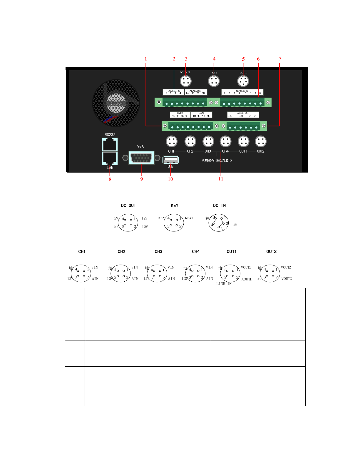
2.3 Rear Panel Interface Description
Note: Please refer to DVR product for actual rear panel interface.
Page 7
User Manual of DS-8000HMFI Mobile DVR
Page 7 Total 104
2.3.1 Rear Panel Description
Num Physical interface
Interface
description
Connection description
1
RS-485 (T+ T- R+ R-)
CAN (1H 1L 2H 2L)
8-pin bayonet
catch with flange
485 interface for PTZ decoder, etc
CAN bus interface
2
ALARM IN (1 2 3 4)
ALARM OUT (1A 1B 2A 2B)
8-pin bayonet
catch with flange
Alarm input interface
Alarm output interface
3 DC OUT
4-pin avigation
interface
Output +12V DC or +5V DC
4 KEY 4-pin avigation Connect to vehicle ignition switch
Page 8

User Manual of DS-8000HMFI Mobile DVR
Page 8 Total 104
interface
5 DC IN
5-pin avigation
interface
Power in, connect to vehicle
batteries output (24V/12V)
6 SENSOR IN (1 2 3 4 5 6 7 8)
8-pin bayonet
catch with flange
Vehicle driving record interface
7 AUDIO OUT (+L - +R – G G)
6-pin bayonet
catch with flange
2 channel audio amplifier output
8
RS-232
LAN
RJ45
RJ45
DTE serial interface
Network interface,connect to
network switch, etc
9 VGA
DB15 female
connector
VGA output interface
10 USB USB interface Connect to USB device
11
CH1~CH4
OUT1
OUT2
4-pin avigation
interface
Video channel 1~4, audio in/ 12V
output
Video output1/audio output1/LINE
IN
Media video output
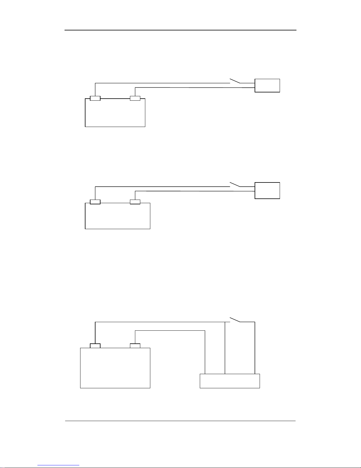
2.3.2 Batteries and ignition switch connection
Special Notice: The KEY wire of ignition switch must be connected, otherwise the
device cannot boot successfully.
Power line from batteries should be directly connected to “DC IN + + - -” interface, and the
“KEY + -” boot control signal should be connected to vehicle ignition switch.
“DC OUT +12V G” should be connected via bayonet catch to camera or other device
which requires +12V DC power supply.
“DC OUT +5V G” should be connected via bayonet catch to other devices which require
+5V DC power supply.
Note: Please pay attention to +/- connection o f po wer wire.
Please kindly take notice that the ignition switch must be connected correctly. There are 2
types of ignition switch, the cathode ignition switch and anode ignition switch
Page 9
User Manual of DS-8000HMFI Mobile DVR
Page 9 Total 104
(1) Cathode ignition switch
Cathode ignition switch is connected to vehicle battery DC+12V/24V.
Cathode ignition switch
+12V/24V GND
(2) anode ignition switch
Anode ignition switch is connected to vehicle battery GND.
Anode ignition switch
GND +12V/24V
Please kindly follow the above steps on connecting ignition switch to init the device correctly.
Note: Please contact your vehicle battery manufacturer for the battery polarity
questions.
(1) Connection for Cathode ignition switch
Connect DVR “DC IN +” with vehicle battery DC+12V/24V.
Connect ignition switch with DVR “KEY+”.
Connect DVR “KEY-” and “GND” with vehicle battery GND pin as the figure below.
Cathode ignition switch
+12V/24V GND
DC IN-
KEY- DC IN + KEY+
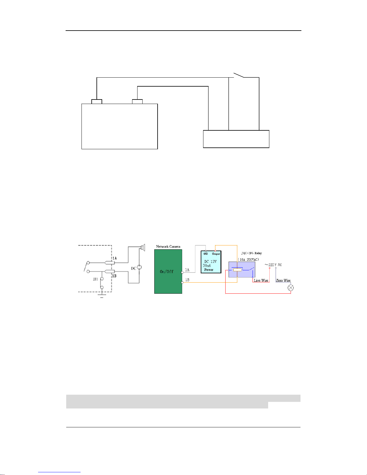
(2) Connection for anode ignition switch
Connect DVR“DC IN +” and ”KEY+” with vehicle battery DC+12V/24V.
Battery
Load
Battery
Load
Battery
DVR
Page 10
User Manual of DS-8000HMFI Mobile DVR
Page 10 Total 104
Connect ignition switch with DVR“KEY-“.
Connect DVR “DC IN –” and vehicle battery GND as the figure below.
Anode ignition switch
GND +12V/24V
DC IN+
KEY+ DC IN- KEY-
After the ignition switch is on (vehicle starts), then the mobile DVR should also init. When
the ignition switch is off, then the mobile DVR will automatically shut down after preset time
period. Please refer to Chapter 5.8 for delay period setting.
2.3.3 Alarm Output Connection Guide
Alarm Output Connection Example
Please kindly pay attention to different connection for JJ1. While connecting to DC load, the
2 connection mode for JJ1 are both okay,yet it is suggested to use it under 12V,1A. While
connecting to AC load,then JJ1 must be open(unplug the short-circuit port on main board).
For safety consideration, it is recommended to use external relays while connecting to AC
load(As the right side figure shows).There are 4 short-circuit port on main board that refers
to each alarm output channelas JJ1, JJ2, JJ3, JJ4, which are all in short-circuit mode by
default, and must be unplugged while connecting to AC load.
Wanings!Short-circuit port must be unplugged on connect to AC load, and users
should also use external relays to avoid device damage and shork hazard!
Battery
DVR
Page 11

User Manual of DS-8000HMFI Mobile DVR
Page 11 Total 104
Connection Guide
1. Unplug the green plugs on device;
2. Use screw driver to loosen the screws, and put the signal wire into the bottom of
reeds,then fasten the screws again;
3. Connnect the green plugs into the device again.
Page 12
User Manual of DS-8000HMFI Mobile DVR
Page 12 Total 104
3 Operation Guide
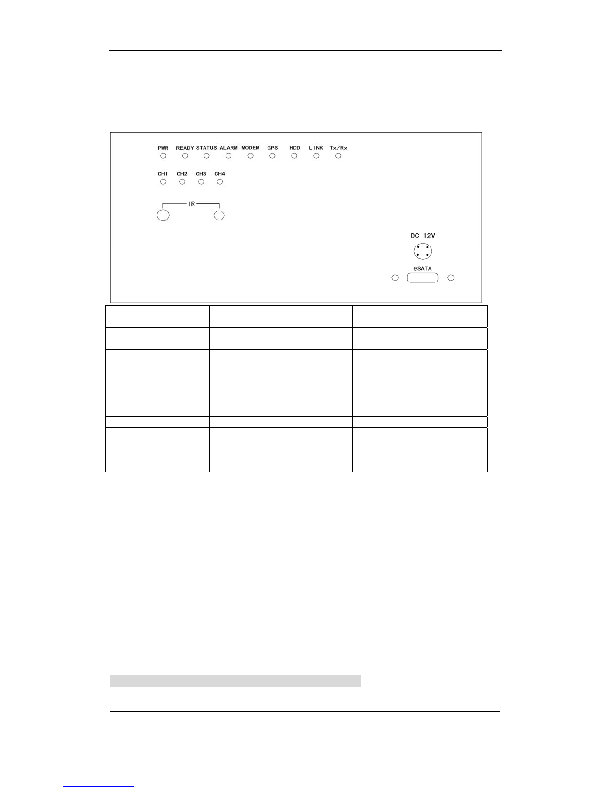
3.1 Front Panel Description
Note: Please refer to the product for actual interfaces.
CH1
Status of
channel 1
PWR Power
CH2
Status of
channel 2
READY Self-detect mode
CH3
Status of
channel 3
STATUS Other Status
CH4
Status of
channel 4
ALARM ALARM lamp
MODEM MODEM lamp
GPS GPS status indicator lamp
HDD HDD indicator lamp
LINK
Nwtwork connection indicator
lamp
Tx/Rx
Network status indocator
lamp
Red light means network transmitting, and green light means on recording; while orange
means network transmitting with network recording.
IR on the left is the IR controller line-in interface, while IR on the left is IR controller signal
receiver.
PWR,READY lamp will be on during a proper device booting, if not, please check power
connection. If power connection is correct then,please contact you dealer.
“DC 12V”is used for DC12V power output and video output for DS-1002HMI (Mobile DVR
Backup Device).
“eSATA” is for eSATA connection of DS-1002HMI.
Note:No device Number is needed for mobile DVR while taking an IR control, users can
directly press the relative function keys for device control.
3.2 IR Controller
Note:Please input default ID/password as “admin”,“12345”.
Please fill battarries into the IR controller, and point the IR sending part to the DVR’s IR
Page 13
User Manual of DS-8000HMFI Mobile DVR
Page 13 Total 104
receiving part.
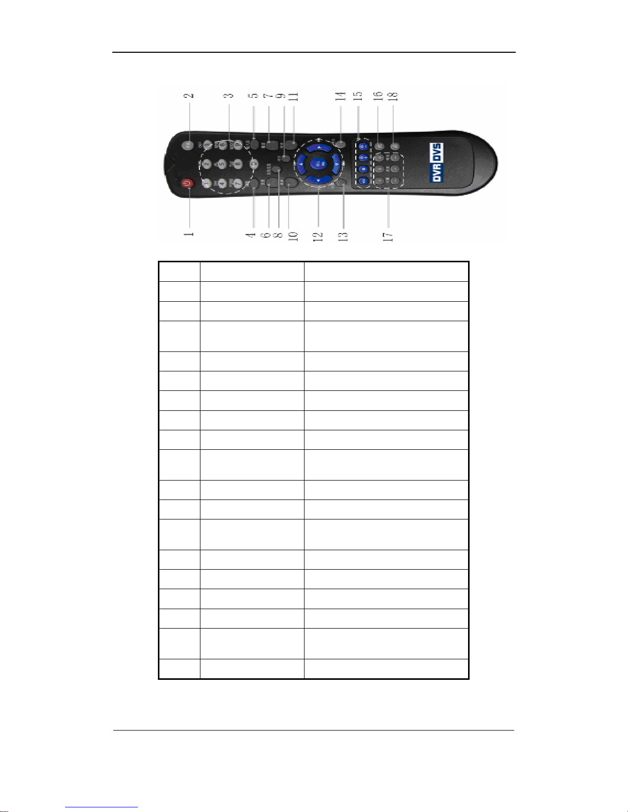
Index Name Description
1 POWER Turnoff device.
2 DEV Enable/Disable IR remote control
3 Numeric Keys
Same as numeric keys of front
panel.
4 EDIT Same as EDIT key of front panel.
5 A Same as A key of front panel.
6 REC Same as REC key of front panel.
7 PLAY Same as PLAY key of front panel.
8 INFO Same as INFO key of front panel.
9 VOIP
Same as VOIP key of frint panel.
For XA-16HSI, same as MON key.
10 MENU Same as MENU key of front panel.
11 PREV Same as PREV key of front panel.
12
Direction Keys
ENTER
Same as direction keys and enter
key of front panel.
13 PTZ Same PTZ key of front panel.
14 ESC Same as ESC key of front panel.
15 Reserved
16 F1
Same as【F1】key of front panel.
17 Lens control
IRIS, FOCUS ZOOM for lens
control.
18 F2
Same as【F2】key of front panel.
If IR controller cannot work properly, please kindly check:
Battary volume and polarity;
Page 14

User Manual of DS-8000HMFI Mobile DVR
Page 14 Total 104
Wether blocked during transmission
Any Fluorescent nearby
Note: Please contact your dealer if the IR controller cannot work properly after all the above
issues have been excluded.
Page 15

User Manual of DS-8000HMFI Mobile DVR
Page 15 Total 104
3.3 Menu Description
3.3.1 Menu Items
Menu Name Function Menu Name Function
Display
Video standard
Brightness
Menu transparency
Unit name
Device ID
Require password
Screen saver time
VGA resolution
Date and Time
Image
Camera name and position setup
Adjust Brightness, Contrast, Hue
and Saturation
OSD Display mode, position and
OSD format setup
Mask area setup
View tampering area and
response setup
Video signal loss
Motion detection sensitivity, area
and response setup
Recording
Overwrite/Stop recording
Resolution and recording
parameters setup
Record schedule
PreRecord time
PostRecord time
Network
DVR IP address
DNS IP
Multicast IP address
Remote host IP and port
NAS IP and directory
PPPoE username and password
Alarms
Alarm input type (Normal open/
Normal close)
Alarm response and PTZ
linkage
Alarm output and schedule
Exceptions
Exceptions type
Exceptions response
PTZ
PTZ parameters
Preset setup
Sequence setup
Cruise setup
RS232
RS232 parameters
RS232 work mode
Preview
Preview mode
Switch time
Enable/Disable audio preview
Preview layout
User
Password
Add or delete user
Password setup or modification
User rights setup
Page 16
User Manual of DS-8000HMFI Mobile DVR
Page 16 Total 104
Media player
Line
Movie
Utilities
Restore parameters
Upgrade firmware
HDD management
Clear alarm output
Reboot
Power off
View log
System information
3.3.2 Menu Operation
How to enter into menu mode
z Press[MENU]key to enter into DVR main menu.
z Press[PLAY]short key to enter into playback menu.
z Perss[REC]short key to enter into manual record menu.
z Perss[PTZ]short key to enter into PTZ control interface.
Notes: You must input user name and password. The default user name is “admin” and
password is “12345”.
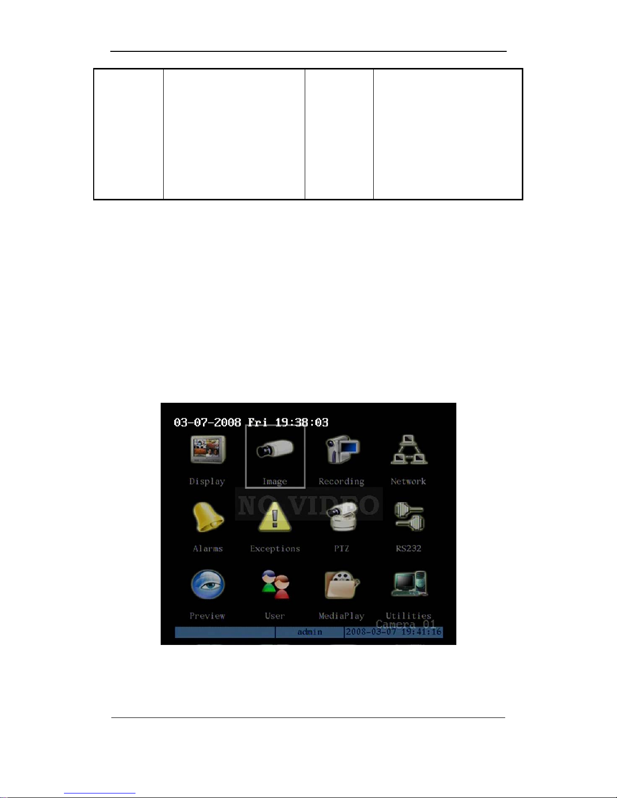
Main Menu Description
The main menu interface is following:
There is one small rectanglar frame named “Active Frame”. It can be moved from one
icon to another by using [Æ]or[Å]key. When the “Active Frame” is located on one icon, you
can press[ENTER]key to enter into the secondary menu. For example, move the “Active
Frame” to “Image” icon, press [ENTER]to enter into the secondary menu as following:
Page 17
User Manual of DS-8000HMFI Mobile DVR
Page 17 Total 104
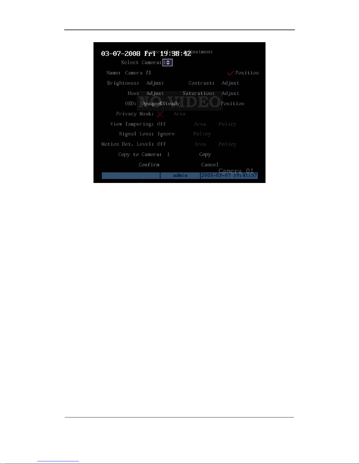
Each menu contains different kinds of items. There is a small rectangular frame named
“Active Frame” which is pointing to the selected item. This “Active Frame” can be moved by
[Æ]or[Å]keys. There are such kinds of menu items:
a) Check Box: Provide 2 options, “9” means enable and “×” means disable. You can
use [ENTER]or[EDIT]key to switch over.
b) List Box: Provide more than 2 options. However, only one of them can be selected.
You can use[↑]and[↓]to select one option. For example, on the right side of “Select
Camera”, there is a list box for you to select one camera.
c) Edit Box: This is for you to input characters. Press[EDIT]key to enter into edit status,
you can input characters as following:
i. Press[A]key to select number, upper case, lower case or symbols;
ii. Use[Æ]and[Å]keys to move cursor;
iii. Use[EDIT]key to delete the charcter in front of cursor;
iv. Press[ENTER]or[ESC]to exit edit.
d) Button: Excute a special function or enter into next sub-menu. For example, press
“Policy” button to enter into sub-menu. Press[Confirm]to save parameters and return
to parent menu. Press[Cancel]button to cancel and return to parent menu. The
button in grey means it can be operated only after it is enabled.
How to exit menu
Press[PREV]key to exit menu and return to preview mode.
Page 18

User Manual of DS-8000HMFI Mobile DVR
Page 18 Total 104
3.4 Character Input
In the menu interface, if you enter into edit status (for example, in the “camera name” edit
box), at the bottom of screen, the input status is appeared:
Here it means you can press numeric keys to input digital number.
Press[A]key to change input methods. You can select “number”, “Uppercase”,
“Lowercase” or “Symbol”.
Uppercase
Lowercase
Symbol
There are 24 symbols in all. They are divided into 4 pages, and you can use[0]key to turn over
page.
Page 19
User Manual of DS-8000HMFI Mobile DVR
Page 19 Total 104
Chapter4 Basic Operation Guide
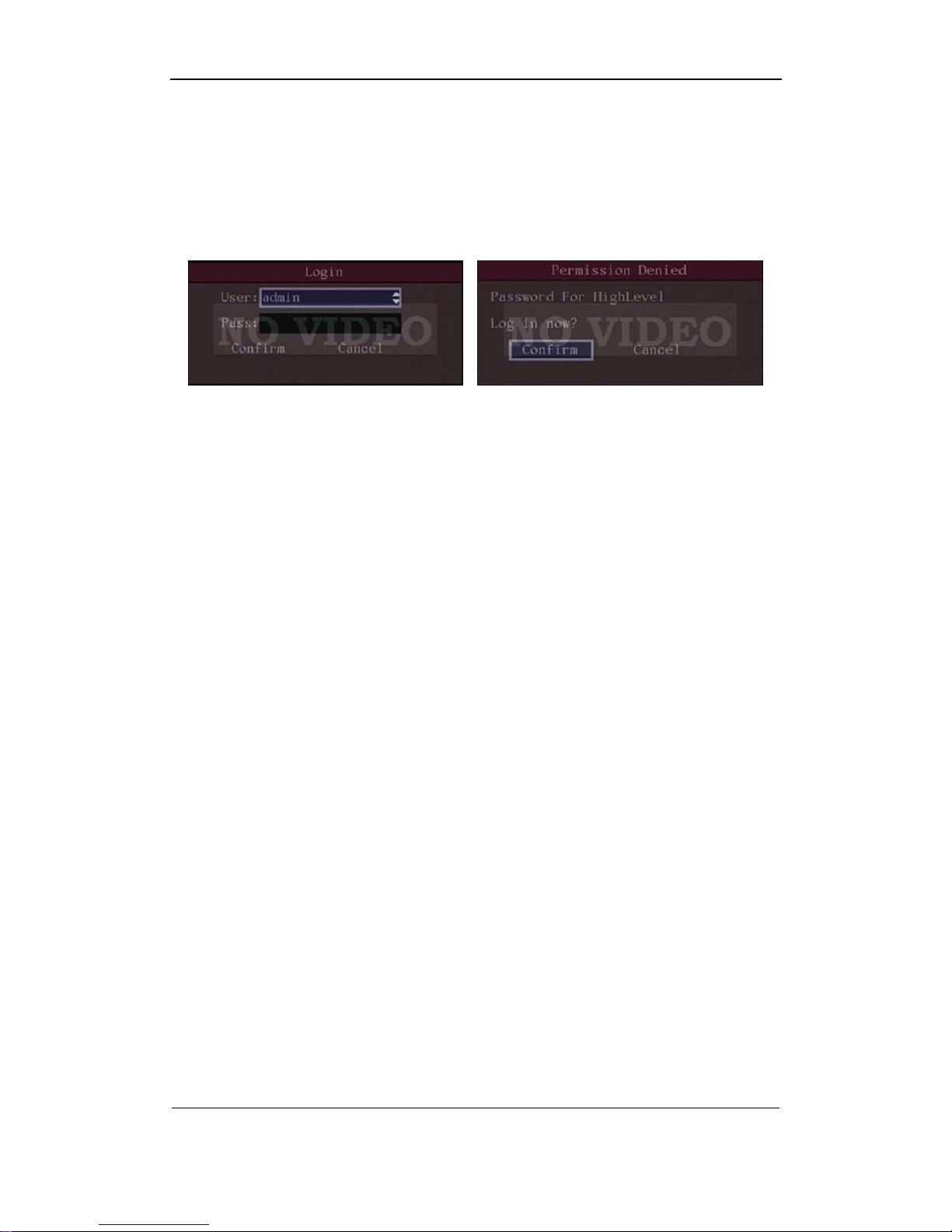
Notice: in this part, the user must have the operate rights, otherwise he can not do any
operation. In this case, a dialoge will popup as bellow.
4.1 Power on
Note: Please make sure the power supply matches DVR and AC cable connected
correctly. Before switch DVR on, please connect one monitor with VOUT or VGA
interface. Otherwise, you can not see graphic user interface and can not do operation.
If[POWER]lamp is off, please do as following:
Step1: Connect AC cable correctly;
Step2: Switch on the power button on the real panel.
If[POWER]lamp is in red, just press[POWER]button to start DVR.
When DVR is started,[POWER]lamp is in green. On the monitor or VGA display, DSP and
HDD initialization process will be shown.
The first line represents DSP initialization. If the DSP icon is “×”, it means that the DSP is
initialized error, please contact administrator at once.
The second line represents HDD initialization. Icons of IDE1 master and slaver HDDs,
IDE2 master and slaver HDDs, etc are displayed. If the HDD icon is “×”, it means the
corresponding HDD is not installed or not detected. If HDD is not detected, please contact
administrator.
Note: If HDD is not installed or not detected, DVR will beep for alarm. You can disable
the audio warning option of HardDiskError in the “Exceptions” menu.
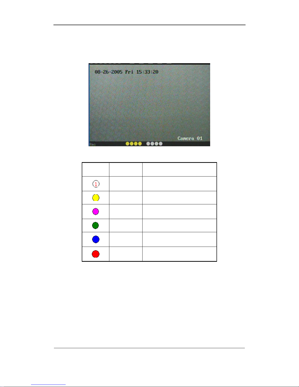
4.2 Preview
DVR will enter into preview mode after it is started.
On preview screen, you can see date, time, camera name and camera status icon.
Page 20
User Manual of DS-8000HMFI Mobile DVR
Page 20 Total 104
In the screen, it will display record and alarm status of each camera. These two kinds of
status will switch over automatically.
Press [A] key to display or hide the camera status bar.
Camera record status is following:
Icon Icon Color Status Description
White No video signal
Yellow Vdieo input
Pink Manual recording
Green Real time recording
Blue Motion detect recording
Red External alarm recording
Page 21
User Manual of DS-8000HMFI Mobile DVR
Page 21 Total 104
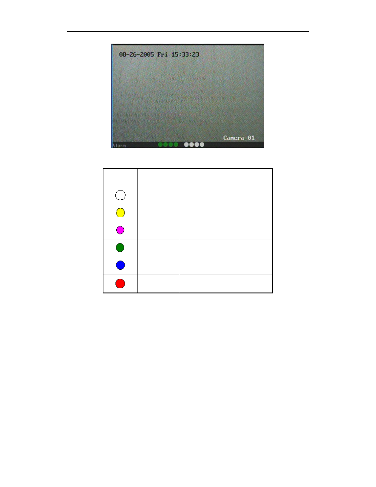
Camera alarm status is following:
Icon Icon Color Status Description
White Video signal lost
Yellow View tampering alarm
Pink Motion&External alarm
Green No alarm
Blue Motion alarm
Red External alarm
Press numeric keys to switch over individual camera preview.
Press[EDIT]key of the IR controller to manual cycle preview. You can set the auto preview
mode in “Preview” menu, referring to 5.2.6.
Press[PREV]key in the IR controller to display multi-screen perview.
Nitices: if the DVR have the GPS(optional) function, please put the GPS antenna on the
top of the bus. When the GPS satellite pass, the posite of the bus and the speed will be show
in the channel 1 left down side.
Page 22
User Manual of DS-8000HMFI Mobile DVR
Page 22 Total 104
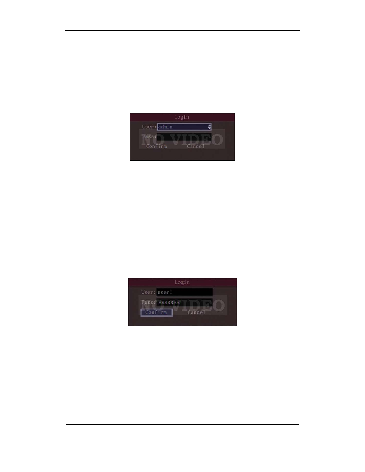
4.3 User name and password
Note: When DVR is delivered from factory, there is only one default administrator
named “admin”, and password is “12345”. The administrator’s name can not be
modified, while the password can be modified. The administrator can create 15 users
and define their user rights.
Login
Login dialog is following:
Use[Ç]/[È]keys to select one user, perss[Æ]key to enter into “Password” edit box, input
corresponding password, press[ENTER]key to exit edit box. The “Active Frame” will be moved
to “Confirm” button. Press[ENTER]key to enter into main menu. If there is beeper alarm, it
means the user name and password are not matched. After three error times, DVR will enter
into preview mdoe.
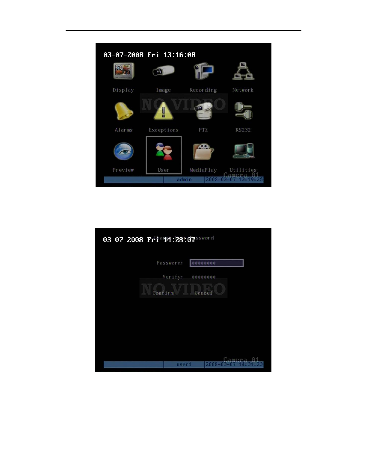
Modify password
For those users created by admin, they can modify their password as following:
Step1: Enter into main menu
Press[MENU]key, in the login dialog, select your user name, input the correct password,
you can enter into the main menu.
Page 23
User Manual of DS-8000HMFI Mobile DVR
Page 23 Total 104
Setp 2: Enter into password modification menu
Move the “Active Frame” to “Password” icon by using[Æ]/[Å]keys. Press[ENTER]key to
enter into following password menu:
Step 3: Input new password
Press[EDIT]key to enter into edit box. You can use numeric keys to input new password.
The password can be null. It also can be 16 numerals. Press[ENTER]to exit edit box, and
move to “Verify” item to input the verify password.
Page 24

User Manual of DS-8000HMFI Mobile DVR
Page 24 Total 104
Note: In edit box, use [Æ]/[Å]to move cursor and[EDIT]key to delete the numeral in
front of the cursor.
Step 4: Modify password successfully
Move the “Active Frame” to “Confirm” button, press[ENTER]key. If the password is
modified successfully, you will get the main menu. Or an error dialog will be pop up. You can
repeat step 3 to modify again.
4.4 PTZ Control
Notice: The user must have the “PTZ control” right.
Under the menu mode, press the “PTZ” to enter into the PTZ control interface.
IR controller button introduction:
Direction control keys: [
], [ ], [ ], [ ]
ZOOM control keys: [ZOOM+],[ZOOM-];
FOCUS control keys: [FOCUS+],[FOCUS-];
IRIS control keys: [IRIS+],[IRIS-];
Adjust preset keys: [REC/SHOT]+three [numeric key]; example: “001” means call
preset 1.
Auto control key: [PLAY/AUTO];
Exit the PTZ control operation menu
If you want to do the other operation, such as playback, manual record and so on, you
need to exit the “PTZ” operation menu. Press the “ESC” button to exit and go back to the
preview mode.
4.5 Manual Record
Note: The user must have the corresponding right, DVR has HDD and HDD is formatted
already.
In preview mode, press [REC] key, in the pop-up login dialog, select the user name and
input the correct password, you can enter into the “Manual Record” interface.
In menu mode, press [REC] key to enter into “Manual Record” interface directly.
Page 25
User Manual of DS-8000HMFI Mobile DVR
Page 25 Total 104
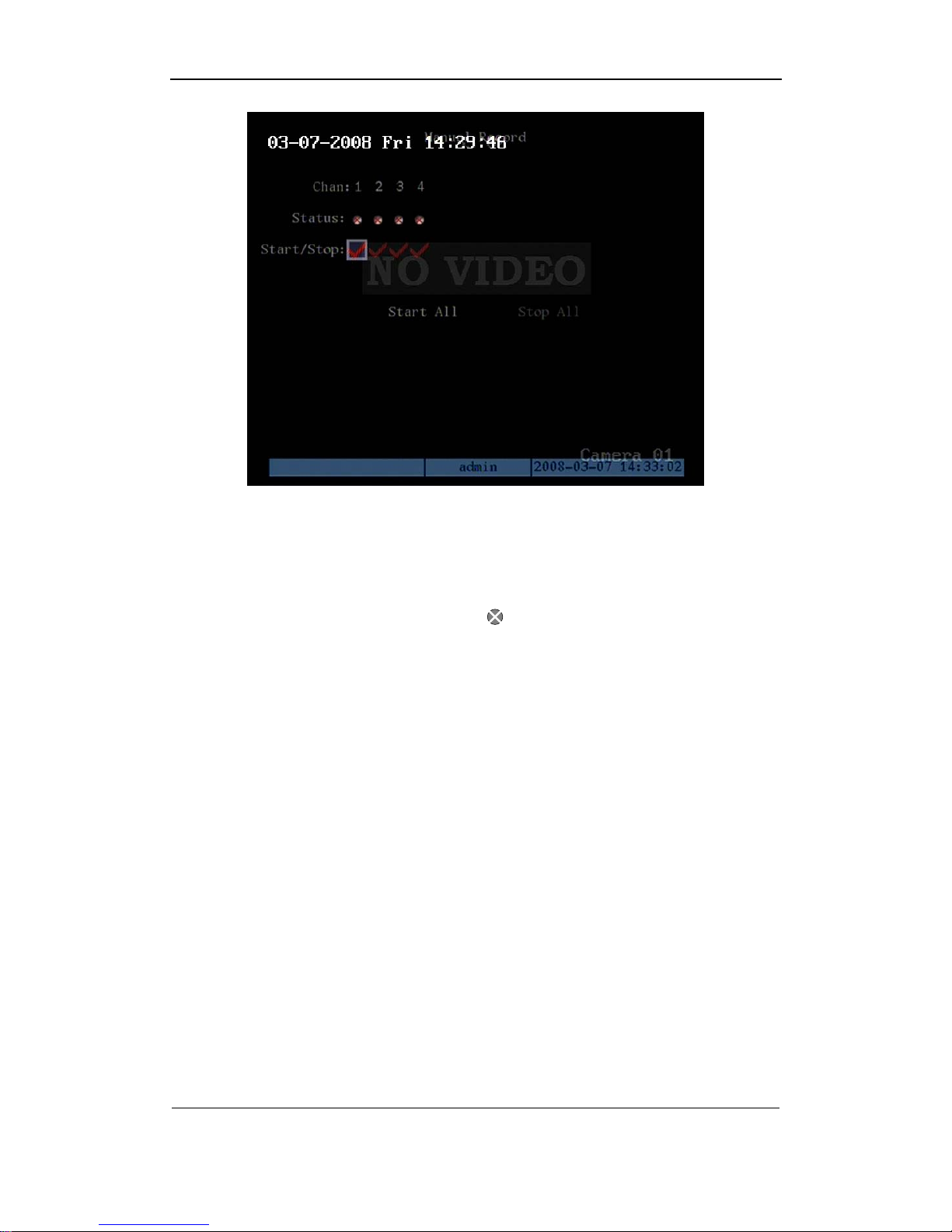
Description
Manual record interface has following parts: channel number, channel status, start/stop
record, start all and stop all buttons.
Channel: List the channel number that DVR has.
Status: Channel work status has 4 cases:
means idle. Green means the channel is
recording (including real time recording, alarm recording, motion detection recording). Red
means network tramsmission. Orange means both recording and network transmission.
Start/Stop: “9” means you can start corresponding channl recording. “×” menas you can
stop recording.
Start All: Press this button to start all channels recording.
Stop All: Press this button to stop all channel recording.
Exit manual record
Press[ESC]key to enter into preview mode. Press[MENU]key to enter into main menu.
Press[PLAY]key to enter into playback menu. Press[PTZ]key to enter into PTZ control mode.
Notice: the manual record will be disabled after the DVR reboot.
4.6 Playback
Notice: The user must have “Playback” right.
Playback interface
In preview mode, press [PLAY] key, in the pop-up dialogin dialog, select username and
input correct password, you can enter into “Playback” interface.
Page 26
User Manual of DS-8000HMFI Mobile DVR
Page 26 Total 104
In menu mode, press [PLAY] key, you can enter into “Playback” interface directly.
One Channel Playback
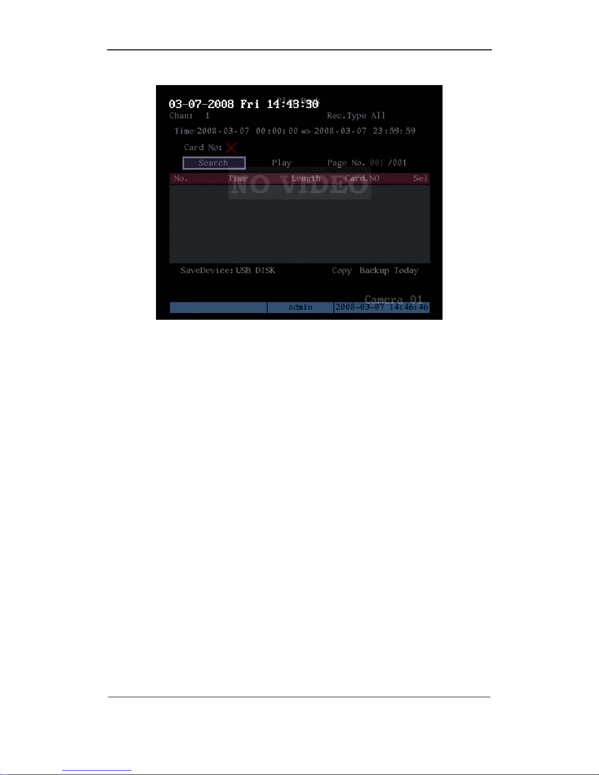
Description
Channel: Use [↑] or [↓] key to select one channel.
Rec Type: Use [↑] or [↓] to select recorded files type. The file type options have “All”, “All
Time”, “Motion Detect”, “Alarm” and “Manual”.
Time Section: You can define the search time section. Move “Active Frame” to the time
edit box, use numeric keys to input the detail time.
Card Number: DVR can get text number through RS-232 or network port. You can use
the text to search the recorded files and playback them. Use the numeric keys to input the text
number.
Search: Search the matched reorded files and display them in the list box. If there is not
matched file, a corresponding dialog box will be pop-up.
Play by Time: Playback the recorded stream directly based on the time section.
Select Page: In the file list box, each page will only display 8 files. If the matched files are
more than 8, you can select page to list other files. 500 pages (4000 files) can be searched in
one time. You can use numeric keys or [↑] [↓] keys to select page.
Page 27
User Manual of DS-8000HMFI Mobile DVR
Page 27 Total 104
File List Box: List the matched files. File started time, file size are displayed in the list
box.You can use [↑] [↓] keys to move the scroll bar to select file.
Backup Devices: You can select USB flash, USB HDD, USB CD-R/W or SATA device to
backup the files or clips.
Copy: Start to backup.
Backup Today: Backup all recorded files of today.
Three kinds of playback mode
1. Search and playbck file: In the playback interface, you can select main channel,
second channel (2-ch palyback), record type, time section. Move “Active Frame” to “Search”
button and press [ENTER] key, DVR will search and list the matched files.
If the matched files are more than 8, you can use “Page No.” to select page (use numeric
keys or [↑] [↓] keys to select page). In the file list box, use [↑] [↓] keys to move the scroll bar to
the file, press [ENTER] key to playback the file.
If DVR can not find the matched files, a failure dialog will pop-up.
2. Playback by Time: In the playback interface, select main channel, second channel
(2-ch playback), record type and time section, move “Active Frame” to “Play” button, press
[ENTER] key, DVR will start to playback based on time section.
3. Search by Card No and Playback file: In the playback interface, select main channel,
Page 28
User Manual of DS-8000HMFI Mobile DVR
Page 28 Total 104
second channel (2-ch playback), record type, enable card No. search option (“9”) and input
the card number, move “Active Frame” to “Search” button, press [ENTER] key, DVR will
search and list the matched files. If the matched files are more than 8, you can use numeric
keys or [↑] [↓] keys to select page. Use [↑] [↓] keys to move scroll bar to the file, press [ENTER]
key to playback the selected file. If DVR can not find the matched files, a message dialog will
pop-up.
Operation when playback
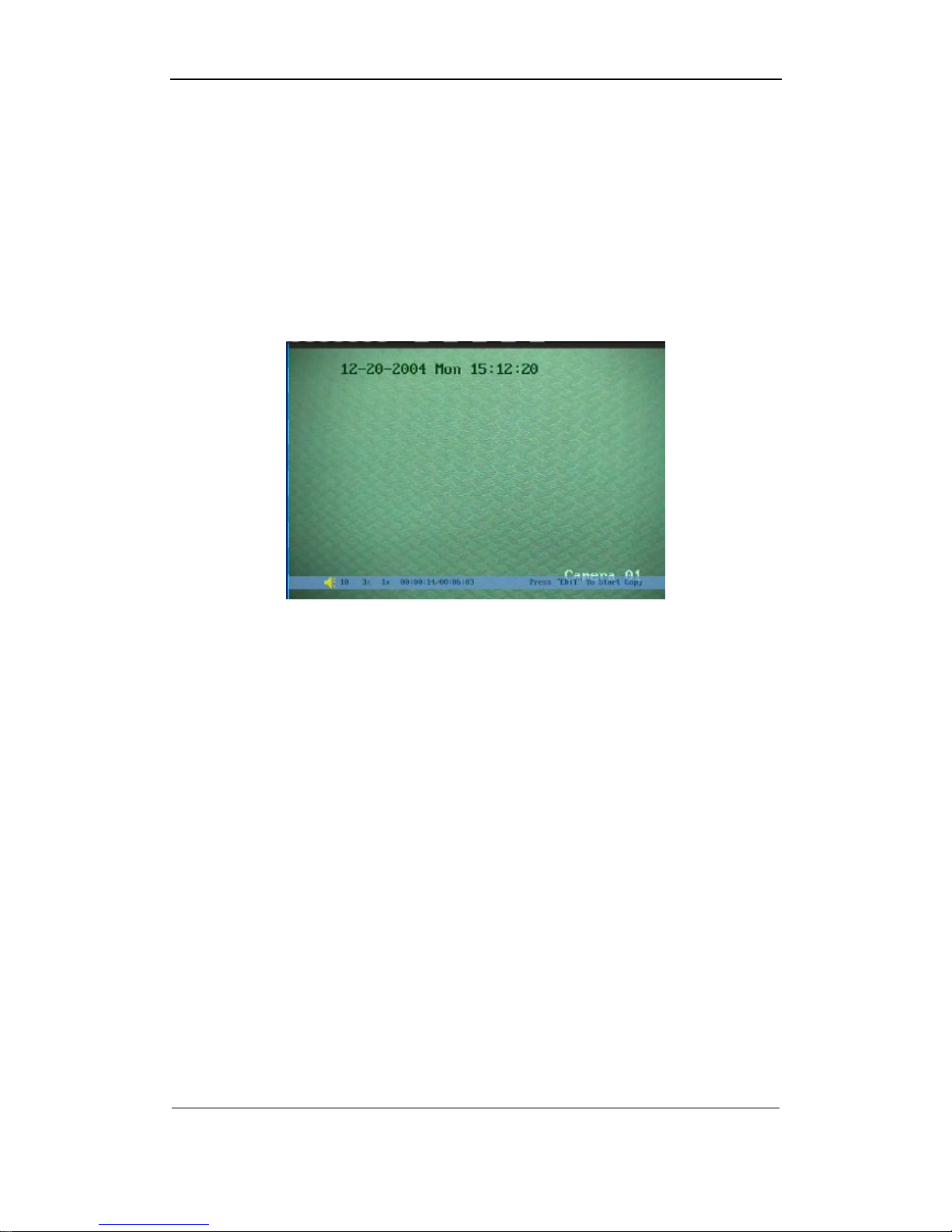
Playback picture:
One Channel Playback
At the bottom of image, there is an information bar and the following information is
included: Volume, Play Progress, Play Speed, Played Time and File Total Time.
z Display/Hide information bar: [MENU]
z Open/Close sound: [PLAY]
z Adjust play progress: [←](Backward),[→](Forward). The unit is “%”.
z Adjust play speed: Normal speed is “1x”. Use [↑]to increase play speed ( 2X, 4X,
8X and MAX). Use[↓]to decrease play speed (1/2X, 1/4X, 1/8X and Frame by
Frame)
z Pause/Continue: Press [ENTER] to pause/continue playback. If played frame by
frame, Press [ENTER] to paly one frame.
z Copy segment:[EDIT]
z Exit: [ESC]
z Playback switch: When in 2-ch playback, press [PREV] to switch between main
channel and second channel.
Exit playback
In playback interface, press [ESC] key to enter into preview mode.
In playback interface, press [MENU] key to enter into main menu, press [REC] key to
enter into manual record, and press [PTZ] key to enter into PTZ control mode.
Page 29

User Manual of DS-8000HMFI Mobile DVR
Page 29 Total 104
4.7 Backup Recorded Files
Note: The user must have “Playback” right. Please connect with backup devices
first. Such as USB flash, USB HDD and SATA device.
Steps of backup via the Esata port:
1. connect the SATA HDD to the eSATA PORT.
2. Enter into the main menu---recording and set the “SATA1 HDD” for backup.
3. Reboot the DVR and enter into the playback menu, after you select the SATA HDD in
the SaveDevice option, you can find the autoback option. Enter into this menu to
format the SATA HDD.
Notice:
1. SATA HDD must connect with the sata1 port (external eS ATA port).
2. you must format the external SATA HDD in the playback---autoback menu. If
you format it in the Utilities---HardDisk menu, there will have only a small space
can be used for backup. Because the backup HDD and record HDD have the
different partition.
This system provide auto backup and self-define backup. The auto backup function
used for backup the file of intraday or the period you setting. It can finish t he backup b y
itself. Self-define backup function need to set the detail period that you want to backup.
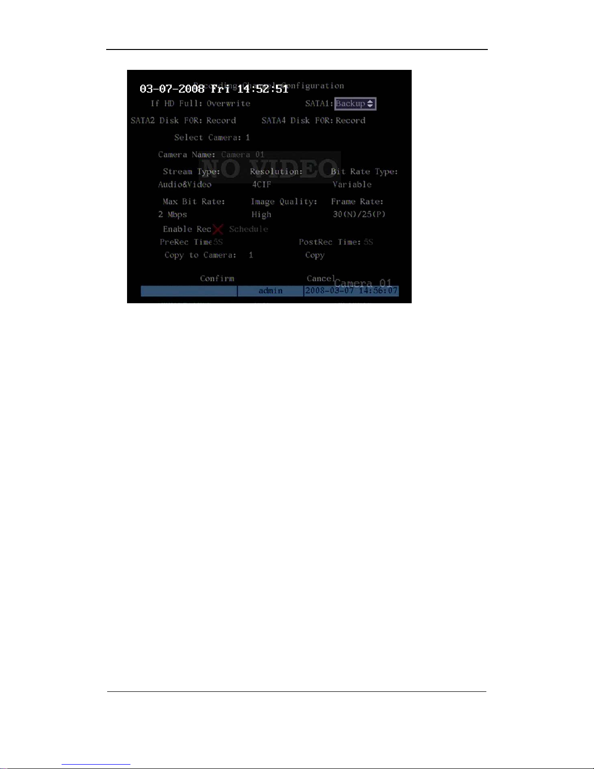
4.7.1 Auto backup
Connect the SATA HDD in the eSATA port, and press the MENU key in the IR controller to
enter into the “Recording” menu, select the option SATA1 to backup. Click “confirm” to reboot
the DVR.
Page 30
User Manual of DS-8000HMFI Mobile DVR
Page 30 Total 104
In the playback interface, you can backup the recorded files.
In the preview mode, press [PLAY] key, in the login dialog, select username and input the
correct password, you can enter into the playback interface.
In the menu mode, just press [PLAY] key, you can enter into playback interface directly.
Backup intraday recorded files
In the playback interface, move “Active Frame” to “Backup Today” button, press [ENTER]
key, all intraday recorded files of all channels will be backup to the save device. A pop-up
dialog will display the backup status.
If bakup device is not connected correctly or DVR do not detect the backup device. Please
ask administrator for more information.
Backup the files that matched your requirement
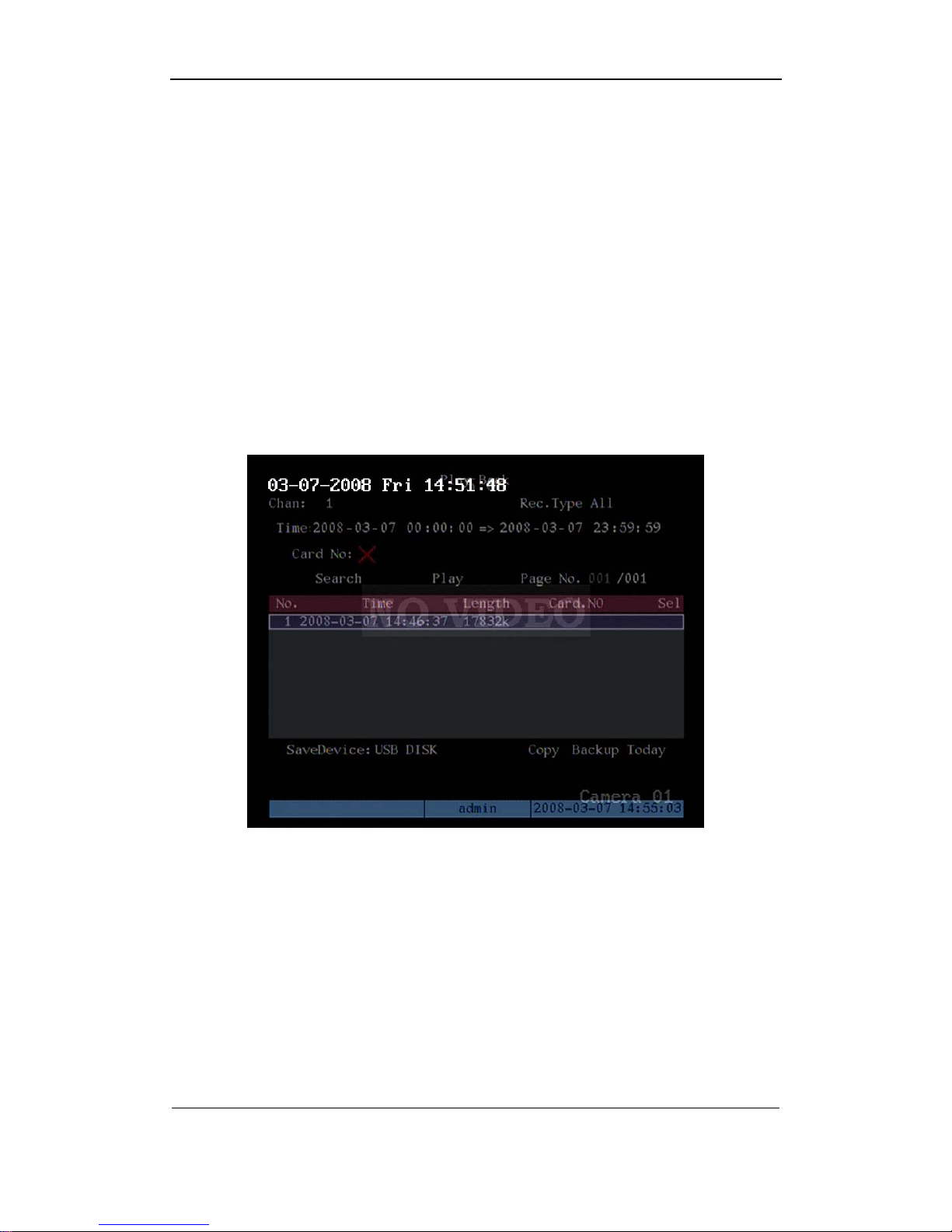
Step 1: Search the matched files
In the playback interface, select one channel and record type, input the time section,
move “Active Frame” to “Search” button, press[ENTER]key, DVR will start to find and list the
matched files.
Page 31

User Manual of DS-8000HMFI Mobile DVR
Page 31 Total 104
Step 2: Select the files that you want to backup
In the file list box, use[↑]or[↓]keys to move the scroll bar. When the scroll bar stays at the
file you wan to backup, press[EDIT]key to select it. The symbol “9” is the selection tag. You
can use the same method to select other files you want to backup. After finish, you can do next
step.
Step 3: Select backup device
Please confirm the backup device: USB flash memory, USB HDD, USB CD-R/W or IDE
CD-R/W, and select the corresponding backup device.
Step 4: Star t and finish backup
Move “Active Frame” to “Save” button and press[ENTER]key to start backup.
When backup is started, corresponding message box will pop-up to indicate the result.
Backup video segment
You also can backup the image segments when the image is being playback. The steps
are:
1) Enter into the interface of playback the files or playback by time;
2) Press[EDIT]key to start selecting the current playback image, and press[EDIT]again
to stop selecting. This segment is slected;
3) You can repeat step 2 to select many segments. 30 segments can be selected in all;
4) After you select all segments, press[ESC]key, a message window will pop-up. If you
press “Confirm” button, DVR will start to backup the selected segments. If you press
“Cancel” button, DVR will abort backup.
Page 32

User Manual of DS-8000HMFI Mobile DVR
Page 32 Total 104
Playback the video segment
You can use our file player software to playback the video segment in PC. You can find
the player software in attached CD.
4.8 Media file import and play
This devide support media play function, before you use the media play function, you
need to import the media file which is prepared already into the DVR, the segment below will
instroduce how to import and how to play the media file.
4.8.1 Make import HDD
Connect the import HDD(SATA HDD) to the eSATA port, then enter into the “recording”
interface (refer to the picture below)
Please make sure the import HDD format is no problem and the space is enough, you need to
put the import HDD into the PC and use the programe editor to make the programe(detail
information please refer to the user manual of the program editor).
Page 33

User Manual of DS-8000HMFI Mobile DVR
Page 33 Total 104
4.8.2 Format the media player HDD
The media player HDD must connect to the forth SATA port. Set the SATA4 to “record&media
play”. After the connection is finished, format the SATA4 in the “Hard Disk” interface. Show as
below.
After the format is finished, the last media player HDD partition is used for saving the media file
and recording the play information, you can not modify the file in the partition. The other
partition can be recorded normally.
4.8.3 Import media file
After you finish the 4.8.1 and 4.8.2. please confirm that the “recording” interace SATA1 is used
for “media import”, SATA4 is used for “record&media play”. After you connect the import HDD
to the eSATA, a dialog will popup and you can select the file to import: line or movie.
Line option:
Enter into the option “line”, popup the “line select” interface, show as the picture below.
Select the line you want to import, press the [EDIT] button to select the line, then press the
[ENTER] button to import the file under this line, includes : prompt when get up the bus,
business advertisement and region advertisement.
Notice: you can import one line at one time, if you import some of the media player HDD, it
will use the latest one for playing.
If the line is not selected, and you press the [ENTER] button to enter into the sub menu-----
4.8.4 movie management
Delect the movie:
Nitice: the movie that is playing can not be deleted!
All the media file in the media HDD can be deleted. Please make sure the media HDD is set to
“record&media play” mode.
4.8.5 play the media file
After the media file is import successfully, you can play the media file. The play mode include
sequence play,random play and continue play after restart play the file. If the system have the
audio output, you can adjust the audio volume freely.
Nitice: when playing, video&audio will be output from the AUX output. The audio output
module is optional, please notice when you purchase.
Page 34

User Manual of DS-8000HMFI Mobile DVR
Page 34 Total 104
1. Sequence play
After the system power on, press the [Æ] button in the preview interface, it will start with the
get up prompt, play the movie in sequence, if there have advertisement file, the business
advertisement will be played according to the interval (the interval can be set in the software
“programe Editor”), after the business advertisement is over, the movie will be continue; if
there have the region advertisement in the line, and the system have the GPS system, after
the vehicle arrived the related area, the system will stop playing the movie and start to play the
business advertisement, then continue the movie. You can press the [ENTER] button to pause
or start the movie while you are playing the movie. But if you are playing the business
advertisement, you can not press the [ENTER] button to pause or start the advertisement.
2. Manual play
When playing, you can press the [↓] to stop the play of movie, and start the next movie. Press
the [↑] button to stop the current one and start the next movie. When you are playing the movie,
you can press the [ENTER] button to pause and start the movie.
Nitice: if the system has the audio output, you can adjust the audio volume freely.
3. Random play
In the preview interface, press the [ENTER] button, play the get up prompt first, then the movie
will be played random, but each movie will be played only one time in one circle. Press the
[ENTER] button to pause or start the movie.
4. Break and continue play
The system has the break and continue function. In the preview interface, press [←] button,
the system will jump over the get up prompt and start from the point that last time stopped.
Press the [ENTER] button to pause and start the movie.
Nitice: after the import is formatted successful, you need to put this import HDD into the PC,
then use the grogram Editor to make the program for the import HDD(please refer to the user
manual of the program editor), then you can connect the import HDD to the eSATA port to
import the media file.
Page 35

User Manual of DS-8000HMFI Mobile DVR
Page 35 Total 104
Chapter5 Parameters Setup Guide
Only the users that have “Parameters Setup” right need read this chapter. When the
following parameters are modified and saved, you must reboot the DVR to make the new
parameters take into effective. Other parameters do not need to reboot.
z Any network parameters
z Stream type, resolution and record schedule
z External alarm sensor type
z View tampering alarm schedule
z Video lost alarm schedule
z Motion detection alarm schedule
z External alarm schedule
z Alarm output schedule
z Transaction
z RS232 work mode
z Change video output standard
5.1Basic setting
5.1.1 Administrator and Password
When DVR is left from factory, there is one default administrator. The name is “admin” and
password is “12345”. The name can not be changed, while the password can be.
Password modification
Press[MENU]key, in the login dialog, select the username as “admin”, use[→]key, move
cursor to password edit box, input “12345”, press “Confirm” to enter into administrator menu.
Page 36

User Manual of DS-8000HMFI Mobile DVR
Page 36 Total 104
Move “Active Frame” to “User” icon, press [ENTER] key to enter into “User Management”
menu.
In the user name list box, only “admin” is existed. You can use[→]key, move “Active
Frame” to password edit box, and press[EDIT]key to enter into edit status. Press numeric keys
to input the new password. The password is only combined by 16 numerals at most. After you
finish inputting password, press[ENTER]key to exit. Move “Active Frame” to “Verify password”
Page 37

User Manual of DS-8000HMFI Mobile DVR
Page 37 Total 104
edit box, input the verify password. Move “Active Frame” to “Confirm” button, and press
[ENTER], if password and verify password are the same, the password will be saved and
taken into effective.
If password and verify password are not same, a warning message box will be appeared.
In this case, press [ENTER] to return password edit box, and input new password again.
5.1.2 Add and Delete User
Enter into “User Management” interface.
Add user
The steps are following:
Step 1: Enter into “User Management” menu
Please refer to chapter 5.1
Page 38

User Manual of DS-8000HMFI Mobile DVR
Page 38 Total 104
Step 2: Add new user name
In the “User Management” menu, move “Active Frame” to “Add” button and press
[ENTER], in the pop-up dialog, input the new user name (refer to chapter 3.4), press
[ENTER]and return “User Management” menu. 15 users can be added in all.
Step 3: Setup the password for new user
After you add one new user, the password is null. You can skip this step if you do not want
to change the password.
In the users list box of “User Management” menu, use[Ç][È]keys to select the new user
name, then use[Æ]key to the password edit box. Press[EDIT]key to enter into edit box, use
numeric keys to input the new password.
Step 3: Setup the rights for ne w user
The new added user has not any operational rights. You must setup rights for him.
In the users list box of “User Management” menu, use[Ç][È]keys to select the new user
name, then use[Æ]key to “Default Rights” button, press[ENTER], the user will have the default
Page 39

User Manual of DS-8000HMFI Mobile DVR
Page 39 Total 104
rights. The default rights include local playback, remote playback and view log.
If you want to define the detail rights, move “Active Frame” to “Setup Rights” button and
press[ENTER]to enter into rights setup menu as following:
Operational rights are divided into “Local Rights” and “Remote Rights”. You can assign
the necessary rights to the user. Use[Æ][Å]key to move “Active Frame” to the corresponding
right items, press[ENTER]or[EDIT]key to enable or disable the item. “9” means assigning the
right to that user.
After you finish, press “Enter” button, the user’s rights will be saved and return “User
Management” menu. If you press “Cancel” button, the user’s rights will be aborted.
Step 4: Save the new user’s password and rights
In the “User Management” menu, press “Confirm” button, the user’s password and rights
will be saved and return main menu. If you press “Cancel” button, the user’s password and
rights will be aborted.
User rights description
“Local Rights”:
Local rights are for local operation, such as the operation using front panel, IR controller
and RS-485 keyboard.
PTZ control: Locally control PTZ;
Record: Manual start/stop recording;
Playback: Local playback and backup the recorded files;
Parameters Setup: Locally setup the DVR parameters;
Page 40

User Manual of DS-8000HMFI Mobile DVR
Page 40 Total 104
Log: Locally view the log on DVR;
Utilities: Locally upgrade firmware, format HDD, reboot DVR and shut down DVR, etc.
“Remote Rights”:
PTZ Control: Remote control PTZ;
Record: Remote manual start/stop recording;
Playback: Remote playback, download the recorded files on DVR;
Parameters Setup: Remote setup the DVR parameters;
Log: Remote view the log on DVR;
Utilities: Remote upgrade firmware, format HDD, reboot DVR and shut down DVR, etc.
Voice: Client talks with DVR;
Preview: Network live preview;
Alarm: Remote control DVR alarm output;
Local Video Out: Remote control DVR video output;
Com Control: DVR RS-232 transparent channel function.
MAC address
This MAC address is not the address of DVR but the PC that will access DVR. If you setup
this MAC address, only the PC with this MAC address can access this DVR.
At PC end, in DOS prompt, you can use “ipconfig” command to get the PC MAC address
(6 bytes).
Delete user
In “User Management” interface, you can use[Ç][È]keys to select one user, then use[Æ],
move “Active Frame” to “Del” button, press[ENTER], in the pop-up confirmation dialog, press
“Confirm” button to delete the selected user and return. Press “Cancel” or[ESC]to abort
deleting.
5.1.3 Unit Name and Dev i ce ID
Unit name
In the “Display” menu:
Page 41

User Manual of DS-8000HMFI Mobile DVR
Page 41 Total 104
There is an item named “Unit Name”. The default unit name is “Embedded Net DVR”.
Move “Active Frame” to unit name edit box, press[EDIT]key to enter into edit status, you can
modify the unit name. About how to input characters, please refer to chapter 3.4.
Press[ENTER]key to finish modification. Select “Confirm” button and press[ENTER], you can
save the new unit name and make it into effect. Press “Cancel” button or[ESC]key to abort
modification.
Device ID:
When you use IR controller to operate DVR, you must use device ID to select DVR. The
default device ID of DVR is “88”. If there are more than one DVR in one place, please define
different device ID for each DVR. Otherwise, the IR controller will control all DVR with the
same device ID at the same time.
In “Display” menu, move “Active Frame” to the device ID edit box, in the edit status, you
can use numeric keys to input new device ID. The device ID value is ranged among 01-255.
After you finish the modification, press “Confirm” button to save and take effect or press
“Cancel” to abort modification.
Page 42

User Manual of DS-8000HMFI Mobile DVR
Page 42 Total 104
5.2 Local preview Setup
5.2.1 Video output standard
There is one VOUT BNC connector at the rear panel of DVR. It is used to connect with
analog monitor and can support PAL or NTSC video output. You can modify video output
standard to match video input.
In “Display” menu:
There is a list box named “Video Output Standard”, you can use[Ç][È]key to select PAL or
NTSC video output.
Notice: the video output standard will become effective after reboot.
5.2.2VGA setup
There is one VGA interface at the real panel of DVR. You can use it to connect with VGA
display. You can define VGA resolution, refresh frequency in “Display” menu.
There are following options: 1024*768/60Hz, 800*600/60Hz and 800*600/75Hz. You can
use [Ç][È]key to select. The screen saver option have: 1 min, 2min, 5min, 10min, 20min,
30min, if you do not want the screen saver, you can select “never”.
Press “Confirm” button to save or “Cancel” to chancel.
Page 43

User Manual of DS-8000HMFI Mobile DVR
Page 43 Total 104
5.2.3 OSD Setup
OSD is abbreviation of “On Screen Display”. For our embedded DVRDVS, it includes
displaying system time and camera name.
OSD settings include: System time, time format, time display position, camera name,
camera name display position, etc.
System Time
In “Display” menu, you can setup DVR system date and time.
Display System Time
You can setup display properties for each camera, including display status, position and
format. Of course, you can copy the properties of one camera to all cameras.
In “Image Setup” menu as following, select one camera:
Page 44

User Manual of DS-8000HMFI Mobile DVR
Page 44 Total 104
Display mode: There are several display modes: Opaque&Steady, Transparent&Steady,
Transparent&Flashing, Opaque&Flashing,
Move “Active Frame” to “OSD” item, you can select one mode.
Display position and format: Move “Active Frame” to “Position” button on the right side
of “OSD”, press [ENTER]to enter into setup image, you can find there are 22*18 (for NTSC,
22*15) small panes, and OSD position is in red. You can use[È][Ç][Æ][Å]keys to move the
OSD position.
Press[EDIT]key to select OSD format. There are following OSD formats:
MM DD YYYY W hh:mm:ss (default)
MM DD YYYY hh:mm: ss
YYYY MM DD W hh:mm:ss
YYYY MM DD hh:mm:ss
Here YYYY means year, MM means month, DD means day, W means weekday, hh
menas hour, mm means minute and ss means second.
Press[ENTER] to save and return “Image” menu or perss to[ESC]abort modification.
Copy parameters: After you setup the properties of one camera, you can copy it’s
parameter to any other camera or all cameras.
After you save the modification, you can find the modification will be taken into effective.
You can perss “Cancel” button or[ESC]key to abort.
Camera Name
Page 45

User Manual of DS-8000HMFI Mobile DVR
Page 45 Total 104
In “Image Setup” menu, you can define name for each camera. Please note that camera’s
name can not be copied.
The steps of camera name setup:
Step 1: Select one camera.
Step 2: Move “Active Frame” to camera name edit box, press[EDIT]key to enter into edit
status, you can input digital number, uppercase and lowercase characters (refer to Chapter
3.4). The camera name can support 32 characters.
Step 3: Press[ENTER]key to exit edit status.
Move “Active Frame” to “Confirm” button, press[ENTER]to save the modification and you
can see the new camera name. Press “Cancel” button or[ESC]key to abort.
Setup Camera Name Position
If you do not want to display camera name, just disable the check box beside camer name
edit box. The disable flag is “×”. If you enable the check box, you can setup the camera name
position. You can copy the position to any other camera. The setup stpes are:
Step 1: Enter into “Image Setup” menu.
Step 2: Select one camera.
Step 3 : Enable the check box on the right side of camer name, then you move “Active
Frame” to “Position” button, press[ENTER]to enter into camera name position setup interface,
in that interface, you can use[È][Ç][Æ][Å]keys to move camera name position. When the
position is fixed, press[ENTER]and return “Image Setup” menu, and press “Confirm” button to
Page 46

User Manual of DS-8000HMFI Mobile DVR
Page 46 Total 104
save it. In the “Image Setup” menu, perss “Cancel” button or[ESC]key, you can abort the
modification.
5.2.4 Video Parameters Setup
For different camera and different background, in order to get the best video image, you
need to adjust video parameters such as brightenss, saturation, contrast and hue, etc.
You can setup the camera individually, and also you can copy the video parameters of one
camera to any other cameras. Here are the setup steps:
Step 1: Enter into “Image Setup” menu:
Step 2: Select camera: Please use[Ç][È]keys to select one camera.
Step 3: Adjust brightness, contrast, saturation and hue: Move “Active Frame” to the
“Adjust” button on the right side of Brightness, Contrast, Saturation and Hue, press
[ENTER]key, you will enter into the corresponding adjust interface. In the adjust interface,
there is one scroll bar at the bottom, you can use[Ç][È]keys to adjust and can find the video
image will be changed at the same time. When you are satisfied with the real time video image,
press[ENTER]to return “Image Setup” menu.
Step 4 : You can copy the video parameters of current camera to any other cameras. Or
you can repeat setp2 and step3 to adjust for any other camera.
After adjust, in “Image Setup” menu, press “Confirm” button to save parameters and make
them into effective. Otherwise, perss “Cancel” button or[ESC]key to abort modification.
Page 47

User Manual of DS-8000HMFI Mobile DVR
Page 47 Total 104
Page 48

User Manual of DS-8000HMFI Mobile DVR
Page 48 Total 104
5.2.5 Mask Area Setup
In some cases, maybe you want mask the sensitive area. This area will not be preview
and recorded. The mask area setup steps are following:
Step 1: Enter into “Image Setup” menu:
Step 2: Select one camera: You can use[Ç][È]keys to select one camera.
Step 3: Enter into mask area setup interface: Enable the check box beside “Privacy
Mask” item, you can press[EDIT]key to change the flag into “9”, and active “Area” button.
Move “Active Frame” to “Area” button on the right side of mask check box, press[ENTER]key
to enter into mask area setup interface.
Page 49

User Manual of DS-8000HMFI Mobile DVR
Page 49 Total 104
Step 4: Setup mask area: In the mask area setup interface, there is one small yellow
pane on the upper left side. For PAL camera, the whole screen is divided into 22*18 panes
(22*15 for NTSC), you can use[↑][↓][→][←]keys to move the yellow pane to your hope position
and press[EDIT]key, the yellow pane will be turned into red, then you can use[↑][↓][→][←]keys
to extend the red pane. This red area is the mask area.
After you make sure the red mask area, press[EDIT]key to save the mask area.
Press[ESC]key to cancel the mask area. The maximum mask area size is 8*8 panes and the
minimum size is only one pane. You can setup 4 mask areas at most.
After you finish setup, press[ENTER]key to return “Image Setup” menu. You can
press[A]key to clear all mask areas.
Step 5: Save mask area: You can repeat step2, step3 and step4 to setup mask area for
other cameras. In “Image Setup” menu, press “Confirm” button to save the mask area, press
“Cancel” bbutton to abort.
If you disable the mask check box, you can cancel the mask area.
5.2.6 Preview Properties
In “Preview” menu, you can setup preview mode, screen switch time, enable or disable
audio preview and preview layout.
Step 1: Enter into “Preview” menu: In the main menu, move “Active Frame” to
“Preview” icon and press[ENTER], you can enter into “preview” menu.
Page 50

User Manual of DS-8000HMFI Mobile DVR
Page 50 Total 104
Step 2: Preview properties:
Select Out: set the output image for each outpout port.
Preview mode: For preview mode item, you can use[↑][↓]key to select one mode. If DVR
has only 1 channel, you can select only “1 Screen” option. If DVR has 4 channels, there are “1
Screen” and “4 Screen” options. If DVR has more than 4 but less than 9 channels, there are “1
Screen”, “4 Screen” and “9 Screen” options. If DVR has 16 channels, there are “1 Screen”, “4
Screen”, “9 Screen”, “12 Screen” and “16 Screen” options.
Switch time: That is image preview switch time. You can use[↑][↓]keys to select switch
time. There are many options, including “5 Seconds”, “10 Seconds”, “20 Seconds”, “30
Seconds”, “1 Minutes”, “2 Minutes”, “5 Minutes” and “Nerver”. If you select “Nerver”, the
preview image will not be switched automatically. For example, for 16 chanenls DVR, if you
select “4 Screen” preview mode and “20 Seconds” switch time, DVR will cycle display 4
channels image every 20 seconds.
Audio preview: If you enable audio preview (“9”), when you preview single camera, DVR
will play the audio of that channel.
Preview layout setup: There is a square frame divided into many windows. If you select
“4 Screen”preview mode, this frame is divided into 4 windows. Each window represents one
camera. You can move “Active Frame” among the windows. There is one bar under the square
to display the preview order of all cameras.
First select the biggest screen preview mode, for example, for 16-channel DVR, select “16
Screen” preview mode so that all windows are display in the square.
Secondly, move “Active Frame” to one of these windows, press numeric keys to input
camera index. The small window will display that camera number. In this way you can change
the display order. If you press 0 or 00, then the corresponding window will not display live
video.
Page 51

User Manual of DS-8000HMFI Mobile DVR
Page 51 Total 104
After you define the camera perview order, you can select preview mode to meet your
demand.
Save setup: Press “Confirm” button to save preview properties. Press “Cancel” or
[ESC]key to abort.
5.3 Alarm setup
5.3.1 External Alarm Input and Relay Output
You can setup for each external alarm input.
In main menu, move “Active Frame” to “Alarms” icon and press[ENTER]key to enter into
alarms menu:
External alarm input setup:
Step 1: Select one alarm input Use[↑][↓]keys to select one alarm input.
Step 2: Alarm type
This is sensor type. You can select “Normal Open” or “Normal Close” according to the
sensor type.
Step 3: Enter into “Alarm in Handling” sub menu
In the “Alarms” menu, there are two options for “Alarm Handling” item. One is “Ignore”,
and the other is “Handle”. If you select “Handle” option, you can active “Policy” and “PTZ
Linkage” buttons on right side. Move “Active Frame” to “Policy” button and press[ENTER]key,
Page 52

User Manual of DS-8000HMFI Mobile DVR
Page 52 Total 104
you will enter into “Alarm in Handling” sub menu:
Step 4: Alarm trigger record channel setup
You can select channels to record for each alarm input. In the sub menu, you can
use[ENTER]or[EDIT]key to enable record channel. “×” means disable and “9 means enable.
Note: In order to trigger the channel to record, in “Recording” menu, you must enable
recording and select record type as “Alarm” or other related type. Please refer to chapter 5.12.
Step 5: Schedule for alarm handle method
When there is external alarm happened in the schedule, DVR will response according to
the handle methods.
Step 6: Alarm handle method
You can select one or more handle method: “On Screen Warning”, “Audible Warning”,
“Upload to Center” and “Trigger Alarm Output”.
Description: If “On Screen Warning” is enabled, when there is external alarm happened
and DVR is in preview mode, DVR will pop-up the related camera. If you trigger more than one
camera, DVR will pop-up them one by one every 10 seconds. When the external alarm is
disappeared, DVR will restore preview mode.
Step 7: Save setup
In “Alarm in Handling” sub menu, press “Confirm” button and return “Alarms” menu. In
“Alarms” menu, press “Confirm” button to save the parameters.
Step 8: PTZ Linkage
Page 53

User Manual of DS-8000HMFI Mobile DVR
Page 53 Total 104
Move “Active Frame” to “PTZ Linkage” button, press[ENTER]key to enter into “PTZ
Linkage” setup menu:
First select one camera, then select one of following PTZ linkage:
z Preset: Set the flag as “9” to enable preset, in the preset number edit box and input
one preset number that has been setup already. Please refer to chapter 5.15 for
preset setup.
z Sequence: Set the flag as “9” to enable sequence and input one sequence number
that has been setup already. Please refer to chapter 5.15 for sequence setup.
z Cruise: Set the flag as “9” to enable cruise. Please refer to chapter 5.15 for cruise
setup.
Press “Confirm” button to save and return “Alarms” menu. Press “Cancel” button
or[ESC]key to abort and return “Alamrs” menu.
Note: Please make sure that the PTZ you are using can support preset, sequence and
cruise functions. One external alarm input can trigger many cameras PTZ linkage.
Step 9: Copy the parameters to other external alarm input You can copy the
parameters of current alarm input to other external input.
Step 10: Save setup In “Alarms” menu, press “Confirm” button to save the parameters.
Press “Cancel” button or[ESC]key to abort.
Alarm relay output setup
Step 1: In “Alarms” menu, use[↑][↓]keys to select one alarm output.
Page 54

User Manual of DS-8000HMFI Mobile DVR
Page 54 Total 104
Step 2: Select delay time
The delay time is when the alarm is disappeared, the alarm output will continue output
time. The delay time options are: 5 Seconds, 10 Seconds, 30 Seconds, 1 Minute, 2 Minutes, 5
Minutes, 10 Minutes and Manual Stop. If you select “Manual’ option, the alarm output will not
stop until you press “Clear Alarm” button in “Utilities” menu. So the actual alarm output time is
made up of alarm input time and this delay time.
Step 3: Enter into alarm out schedule
You can set the schedule to make alarm output into effective. Move “Active Frame” to
“Schedule” button on right side of “Alarm Out Time” item, press[ENTER]key to enter into the
corresponding schedule menu:
Step 4: Setup alarm out schedule
Like other schedule setup, you can set 4 time periods for one day and 7 days for one
week. When you finish setup, press “Confirm” button to return “Alarms” menu.
Step 5: Copy one alarm output param eters to other alarm output
In “Alarms” menu, you can copy parameters of current alarm output to other alarm output.
Step 6: Save setup
When you finish setup, in “Alarms” menu, press “Confirm” button to save all parameters.
Note: If any schedule is modified, you must reboot DVR to make it into effective.
Page 55

User Manual of DS-8000HMFI Mobile DVR
Page 55 Total 104
5.3.2 Motion Detection Alarm
If you enable this function, when there is motion detected, DVR will make alarm.
Step 1: Enter into “Image Setup” menu:
Step 2: Select camera: Use[Ç][È]key to select one camera.
Step 3: Select motion detection sensitivity: On the right side of “Motion Det. Level”
item, there is a list box. That is motion detection sensitivity. There are 7 options, from 0 (the
lowest) to 5 (the highest) and “Off”. You can use[↑][↓]keys to select one. If you select “Off”
option, DVR will not response even if there is motion detection. If you select other options, it
will active “Motion Area Setup” button and “Policy Setup” button. If you select low sensitivity
such as 0, only when there are great motion detection, DVR can response. On the other side,
for high sensitivity such as 5, DVR will response with small motion detection.
Step 4: Motion area setup: You must define motion areas so that DVR will response
when there is motion in those areas. Move “Active Frame” to “Area” buton on the right side of
sensitivity list box, press[ENTER]key, you can enter into “Motion Area Setup” interface.
Page 56

User Manual of DS-8000HMFI Mobile DVR
Page 56 Total 104
The whole screen is divided into 22*18 panes (NTSC: 22*15). There is one yellow panel
on the upper left side. The motion area setup steps are the same as that of mask area setup
(refer to chapter 5.7). The only differences are that you can use[PTZ]key to set the whole
screen as motion area, and mutil motion areas can be defined. Press[A]key to clear all motion
areas.
Setup multi areas: After you setup one motion area, press[EDIT]key, the yellow pane will
appear again, then you can setup another motion area.
Clear motion area:
Clear part of motion area: Move the yellow pane to the start clear position of motion area,
press[EDIT], you will find the yellow pane is turned into black pane. You can use[↓][→]key to
enlarge or shrink the black area. Press[EDIT]key to clear this part motion area.
Press[Enter]key to save and return “Image” menu. Press[ESC]to cancel.
Clear all motion areas: Press[A]key to clear all motion areas of this channel.
The kyes used to setup motion areas are following:
z [↑][↓][←][→]: Move yellow panel to any position;
z [EDIT]:Yellow panel and red panel switch key:;
z [→]: Right enlarge red pane;
z [←]: Left shrink red pane;
z [↓]: Down enlarge red pane;
z [↑]: Up shrink red pane;
z [PTZ]: Set whole screen as motion area;
z [A]: Clear all motion areas;
z [ENTER]: Save and return “Image Setup” menu;
z [ESC]: Cancel setup and return “Image Setup” menu;
Page 57

User Manual of DS-8000HMFI Mobile DVR
Page 57 Total 104
The motion detection area is displayed as following:
Step 5: Motion alarm policy: Move “Active Frame” to the corresponding “Policy” button
of motion detection alarm, press[ENTER]key to enter into “Motiomn Alarm Handle” menu:
Step 6: Motion alarm record channel setup: When there is motion alarm happened,
you can trigger related camera to start recording. In “Motion Alarm Handle” menu, you can
select one or more record channels. Please use[ENTER]or[EDIT]key to enable the flag into
“9”.
Page 58

User Manual of DS-8000HMFI Mobile DVR
Page 58 Total 104
Note: In order to make the cameras start recording, in “Recording” menu, you must
enable recording schedule and set “Rec Type” as “Motion Detection” or “Motion | Alarm”.
Please refer to chapter 5.12 for recording setup.
Step 7: Motion alarm schedule: When the motion alarm is happened in schedule, DVR
will response such as “On Screen Warning”, “Audible Warning”, “Upload to Center” and
“Trigger Alarm Output”. You can setup 4 time periods for one day and 7 days for one week.
Note: Time periods in one day can not be repeat.
Step 8: Motion alarm handle method setup: You can select one or more handle
methods such as “On Screen Warning”, “Audible Warning”, “Upload to Center” and “Trigger
Alarm Output”.
Description: If “On Screen Warning” is enabled, when there is motion alarm happened
and DVR is in preview mode, DVR will pop-up the related camera. If you trigger more than one
camera, DVR will pop-up them one by one every 10 seconds. When the motion alarm is
disappeared, DVR will restore preview mode.
Step 9: Save motion alarm setup: Press “Confirm” button to return “Image Setup” menu.
In the “Image Setup” menu, press “Confirm” button to save the current camera parameters.
Step 10: Save all cameras: You can repeat from step2 to step8 to setup motion detection
parameters for other cameras. Also you can copy the parameters of one camera to any other
cameras.
Note: Motion alarm area can not be copied.
If you want to disable motion alarm area and motion alarm policy, you just need to select
the motion alarm sensitivity as “Off”.
5.3.3 Video Loss Alarm
When the video cable or camera has something wrong, the video image is lost. If you
enable video loss alarm, in such case, DVR will make alarm.
Step 1: Enter into “Image Setup” menu:
Page 59

User Manual of DS-8000HMFI Mobile DVR
Page 59 Total 104
Step 2: Select camera: Use[Ç][È]keys to select one camera.
Step 3: Enter into “Video Signal Loss Handle” interface: Move “Active Frame” to the
list box on the right side of “Video Loss” item, use[Ç]key to select “Handle” option and move
“Active Frame” to the “Policy” button on right side. Press[ENTER]to enter into “Video Signal
Loss Handle” interface:
Step 4: Setup alarm schedule: You can setup working schedule. Only when the video
Page 60

User Manual of DS-8000HMFI Mobile DVR
Page 60 Total 104
loss is happened in the schedule, DVR will response.
Note: The 4 time periods can not be repeated. Please reboot DVR to make parameters
into effective.
Step 5: Setup alarm policy: You can select one or more response solutions, including
“On Screen Warning”, “Audible Warning”, “Upload to Center” and “Trigger Alarm Output”. You
can use [↑][↓]and [EDIT]key to enable or disable them. “×” is disable and “9” is enable.
Step 6: Save alarm setup: After your setup, press “Confirm” button and return “Image
Setup” interface. In “Image Setup” menu, press “Confirm” button to save current camera
parameters and return main menu.
Step 7: Save all cameras: If you want to setup other cameras, please repeat from step2
to step 6. In “Image Setup” menu, press “Confirm” key to save all cameras parameters. Press
“Cancel” button or[ESC]key to abort.
5.3.4 View Tampering Alarm
If you enable this function, when someone blocks the camera spitefully, DVR will make
warning alarm.
Step 1: Enter into “Image Setup” memu:
Step 2: Select camera: Please use[Ç][È]keys to select one camera.
Step 3: Select sensitivity: You can use[↑][↓]keys to select the sensitivity for “View
Tampering” item. The sensitivity options are: Low, Normal and High. Select one of them will
active “Area Setup” and “Policy Setup” function.
Page 61

User Manual of DS-8000HMFI Mobile DVR
Page 61 Total 104
Step 4: View tampering area setup Move “Active Frame” to “Area” button, press
[ENTER]key to enter into area setup interface. The setup methods are same as that of mask
area setup. After setup the area, press[ENTER]key to return “Image Setup” menu. You can
press[ESC]key to abort.
Only one view tampering area can be setup.
Step 5: View tampering alarm setup In “Image Setup” menu, move “Active Frame” to
“Policy” button, press[ENTER]key to enter into “View Tampering Handle” menu:
Step 6: Alarm schedule setup: When there is view tampering alarm happened, DVR will
handle the alarm based on the schedule. You can set 4 periods for each day one week. Also
you can copy the schedule of one day to other days.
Notes: Time periods can not be repeated. Please reboot DVR to make the parameters
into effective.
Step 7: Setup alarm policy: If there is view tampering alarm happended in schedule,
DVR will response based on the policy. You can select one or more solution including “On
Screen Warning”, “Audible Warning”, “Upload to Center” and “Trigger Alarm Output”. You can
use [↑][↓]and [EDIT]key to enable or disable them. “×” is disable and “9” is enable.
Step 8: Save alarm setup: After your setup, press “Confirm” button and return “Image
Setup” interface. In “Image Setup” menu, press “Confirm” button to save current camera
parameters and return main menu.
Step 9: Save all cameras: If you want to setup other cameras, please repeat from step2
Page 62

User Manual of DS-8000HMFI Mobile DVR
Page 62 Total 104
to step 8. In “Image Setup” menu, press “Confirm” key to save all cameras parameters. Press
“Cancel” button or[ESC]key to abort.
Select “Off” option for “View Tampering”, you can delete the view tampering area.
Note: Only one view tampering area can be setup for each camera. The view tampering area
can not be copied. If the schedule is modified, you must reboot the device to make the
parameters into effective.
5.4 Recording Setup
In main menu, there is an icon named “Recording”. You can enter into recording menu as
following:
5.4.1Recording parameters description:
If HD Full: There are two options: “Overwrite” and “Stop recording”. If you select
“Overwrite” option, when all HDDs in DVR are full, DVR will overwrite the earliest recorded
files and continue recording. If you select “Stop recording” option, when all HDDs are all full,
DVR will handle it as “Hard Disk Full” exception, please refer to chapter 5.17 for exception
menu.
Select Camera: Here all channels are listed. You can use[↑][↓]keys to select one.
Page 63

User Manual of DS-8000HMFI Mobile DVR
Page 63 Total 104
Stream Type: There are two options, one is “Audio&Video” stream and the other is
“Video” stream only. If you want to record video and audio, please select “Audio&Video” option,
otherwise you can select “Video” option to record only video.
Note: If you change this option, please reboot DVR to make parameter into effective.
Resolution: The higher resolution is, the clearer the image is. The resolution options from
low to high are: QCIF, CIF, 2CIF, DCIF, 4CIF.
Note: If you change this resolution option, please reboot DVR to make it into effective.
Bit Rate Type: There are two options: “Variable” and “Fixed”.
If you select variable bit rate, DVR will adjust the actual bit rate according to the video
movement. When there is not much movement, DVR will use low bit rate, while there is much
movement, DVR will use high bit rate. In this case, DVR can save HDD usage and network
bandwidth.
If you select fixed bit rate, DVR will use the fixed bit rate to compress iamge. The bit rate
size is defined in “Max Bit Rate” option. In this case, we can calculate the recorded file size
and network bandwidth that we need.
Max Bit Rate: If you select variable bit rate, when the video input has great movement,
we need to limit the max bit rate. The max bit rate has following options (bps): 32K, 48K, 64K,
80K, 96K, 128K, 160K, 192K, 224K, 256K, 320K, 384K, 448K, 512K, 640K, 768K, 896K, 1M,
1.25M, 1.5M, 1.75M, 2M and “User define”.
The max bit rate selection has relations with resolution. If you select high resolution, you
must select high bit rate. For CIF resolution, the typical max bit rate is 384K-768Kbps. For
DCIF resolution, the typical bit rate is 512K-1Mbps. For 4CIF resolution, the typical bit rate is
1.25Mbps-1.75Mbps. Of course, you will select the proper max bit rate based on the camera,
background and image quality requirement.
Bit rate: You can select bit rate size for fixed bit rate type. It is the same as “Max Bit Rate”.
Image Quality: If you select variable bit rate type, you can define image quality. There are
6 options: Highest, Higher, High, Average, Low and Lowest. High image quality needs high bit
rate size.
Frame Rate: Frame per second. Options are: Full (PAL is 25 FPS and NTSC is 30FPS),
20, 16, 12, 10, 8, 6, 4, 2, 1, 1/2, 1/4, 1/8, 1/16. For low frame rate, you can select low bit rate
size.
PreRecord Time: When you enable motion detection recording or external alarm
recording, you can define prerecord time. The options are: No PreRecord, 5 Seconds (default
selection), 10 Seconds, 15 Seconds, 20 Seconds, 25 Seconds, 30 Seconds and Max
PreRecord.
MaxPreRecord is to save all data in PreRecord buffer. The PreRecord time is related with
Page 64

User Manual of DS-8000HMFI Mobile DVR
Page 64 Total 104
bit rate. The lower bit rate, the longer PreRecord time is.
If the bit rate (Max bit rate) is very low, and you select “PreRecord Time” as “5 Seconds”,
maybe the actual perrecord time is more than 5 seconds. On the other side, if the bit rate is
high, and set “PreRecord Time” as “30 Seconds”, the actual prerecord time maybe is less than
30 seconds.
PostRecord Time: When external alarm or motion alarm is stopped, DVR will continue
recording time. The options are: 5 Seconds (default), 10 Seconds, 30 Seconds, 1 Minute, 2
Minutes, 5 Minutes and 10 Minutes.
Enable Rec: Enable or disable selected camera record function. “×” means disable and
“9” means enable.
5.4.2 Record Schedule setup
When you enable recording function, you can setup recording schedule.
Note: When the camera’s recording schedule is modified, you must reboot DVR to make it
into effective.
All day recording setup:
Step 1: Enter into recording schedule menu
In recording menu, use[ENTER]or[EDIT]key to enable record function (“9” flag), press
“Schedule” button to enter into recording schedule menu.
Page 65

User Manual of DS-8000HMFI Mobile DVR
Page 65 Total 104
Step 2: Select ond day and enable all day recording option
For “Day” item, there are options: Monday, Tuesday, Wednesday, Thursday, Friday,
Saturday and Sunday. Use[↑][↓]keys to select one day. Move “Active Frame” to the check box
on the right side of “All Day” item, press[ENTER]or[EDIT]key to enable “All Day” option. “×”
means disable and “9” means enable.
Step 3: Record type
For “Rec Type” item, the options are: All Time, Motion Detect, Alarm, Motion|Alarm, and
Motion&Alarm.
For all day record mode, only one record type can be selected.
Step 4: Copy to other days
You can repeat step2 and step3 to setup for other days. Also you can copy the current day
to other days.
Step 5: Save
Press “Confirm” back to “Recording” menu. Press “Confirm” again to save the parameters
and return main menu.
None all day recording setup
Step 1: Enter into recording schedule menu
In recording menu, use[ENTER]or[EDIT]key to enable record function (“9” flag), press
“Schedule” button to enter into recording schedule menu.
Page 66

User Manual of DS-8000HMFI Mobile DVR
Page 66 Total 104
Step 2: Select ond day and disable all day recording option
For “Day” item, there are options: Monday, Tuesday, Wednesday, Thursday, Friday,
Saturday and Sunday. Use[↑][↓]keys to select one day. Move “Active Frame” to the check box
on the right side of “All Day” item, press[ENTER]or[EDIT]key to disable “All Day” option. “×”
means disable and “9” means enable.
Step 3: Setup time period and record type
There are 4 time periods for one day, and each time period can select different record type.
Input start time and stop time for each time period, and select record type for each period. The
record type options are: All Time, Motion Detect, Alarm, Motion&Alarm and Motion|Alarm.
Note: The time periods in one day can not be repeat.
Step 4: Copy to other days
You can repeat step2 and step3 to setup for other days. Also you can copy the current day
to other days.
Step 5: Save
Press “Confirm” back to “Recording” menu. Press “Confirm” again to save the parameters
and return main menu.
Note:
1) If record type is “Motion Detect” or other related types, you must setup “Motion Detection”
in order to trigger motion recording .
2) If record type is “Alarm” or other related types, you must setup “Alarms” in order to trigger
alarm recording.
3) The time period is among 00:00—24:00.
5.4.3 Pre-record and post-record setup
Pre-record: it mainly use for the motion detect record and alarm record, the real time depends
on the size of the memory and record bitrate. So the real pre-record time imay be not exact.
Post-record: after the alarm stop, the DVR will continue record for some time.
5.5 Network Parameters
If you want use network to access DVR, you must setup network parameters.
Note: If any network parameter is modified, you must save and reboot DVR to make it into
effective.
In main menu, move “Active Frame” to “Network” icon and press[ENTER], you can enter
into “Network” menu as following:
Page 67

User Manual of DS-8000HMFI Mobile DVR
Page 67 Total 104
“Network” menu description:
*NIC type: Defautl is “10M/100M Auto”, the other options are: 10M Half-Dup, 10M
Full-Dup, 100M Half-Dup and 100M Full-Dup.
*IP address: This IP address must not be conflict with other IP. If there is DHCP server in
network, you can set the IP as “0.0.0.0”, save and reboot DVR. In reboot process, DVR will
search the DHCP server and get one dynamic IP address. This item will display the dynamic IP
address. If DVR uses PPPoE function, also DVR can dialup into internet and this item will
display the dynamic internet IP address.
*Port: Network access port number, must be from 2000 to 65535, the default port is
8000..
*Mask: This is sub net mask.
Gateway: The gateway IP is used to communicate in different network segments
DNS address: If DVR uses PPPoE function, and get one dynamic IP address. If you set
DNS IP with one fixed Internet IP, DVR will send some information such as DVR name, DVR
serial number, DVR current IP to that fixed IP address. We call that fixed Internet IP as DNS IP.
The DNS server with that fixed Internet IP can receive DVR information and used to resolve
DVR dynamic IP.
This DNS is special software, not the normal domain name server. You can use the
provided SDK to develop this DNS software.
Page 68

User Manual of DS-8000HMFI Mobile DVR
Page 68 Total 104
Multicast IP: It is one D-class IP address, among 224.0.0.0 --- 239.255.255.255. If you do
not use multicast function, you do not need to set. Some routers will prohibit multicast function
in case of network storm.
Remote Host IP and Port: If you set this IP and port, when there is alarm and exception
happened, DVR will send information to that host IP. The center with this IP can receive alarm
and exception information from DVR. You can use SDK to develop this center software.
NAS: Network access storage. DVR will regard network HDD as local HDD. If you enable
this function, DVR will send and save the real time image to that network HDD.
NFS IP: The IP of that network storage server.
Dir: The directory name shared by that network storage server.
This function is not available until now.
Http Port: The port is for IE browser. The default value is 80. It can be modified.
PPPoE: DVR support PPPoE dail-up function.
Wireless environment: select “9” means use the wireless transmission mode.
Notice: if you use the wireless environment, you only can view 2 channel image at one
time in the client software.
Plantform login interface: “server IP” means load equipoise server IP.
Port: the port that used for communicating with the load equipoise server, default port is
5660.
Device ID: assigned by the load equipoise server for the DVR. (different from the device
ID in the local display)
Login password: the password for loginning the load equipoise server.
5.6 PTZ
There is one RS-485 port at DVR rear panel used for PTZ control. You can setup RS-485
parameters to match your PTZ protocol. In main menu, move “Active Frame” to PTZ icon and
press[ENTER]key, you can enter into PTZ menu as following:
Page 69

User Manual of DS-8000HMFI Mobile DVR
Page 69 Total 104
PTZ menu description
Select channel: Select one PTZ camera.
RS-485 parameters: Including baudrate, data bit, stop bit, parity, flow control, etc. These
parameters must be the same as those of PTZ. Protocol.
PTZ address: Each PTZ has one different address.
PTZ type: DVR had the following PTZ protocol: YouLi, LinLin-1016, LinLin-820, Pelco-p,
DM DynaColor, HD600, JC-4116, Pelco-d WX, Pelco-D, VCOM VC-2000, NetStreamer,
SAE/YAAN, Samsung, Kalatel-312, CELOTEX, TLPelco-p, TLHHX-2000, BBV, RM110,
KC3360S, ACES, ALSON, INV3609HD, Howell, Tc Pelco P, Tc Pelco D, AUTO-M, AUTO-H,
ANTEN, CHANGLIN, DeltaDome, XYM-12, ADR8060, EVI-D30, DEMO-SPEED,
DM-PELCO-D, ST832, LC-D2104, HUNTER, A01, TECHYIN, WEIHAN, LG, D-MAX,
Panasonic, KTD-348, infinova, PIH-7625, LCU, DennarDome, etc. Other PTZ protocols will be
added with the new firmware.
Note: In DVR “PTZ” menu, if you select Pelco-P protocol, when you setup PTZ address,
please plus or minus one compared with Camera ID. For example, if camera ID is 2, the DVR
PTZ address is set as ID 3.
Preset setup: Preset is using one number to represent the camera’s position, zoom,
focus and iris. Move “Active Frame” to “Setup” button on the right side of “Preset” item,
press[ENTER]key to enter into preset setup menu. You can save 128 preset number. Please
make sure the PTZ support preset function before you setup preset.
Page 70

User Manual of DS-8000HMFI Mobile DVR
Page 70 Total 104
Sequence setup: Each sequence is made up of several curise points. Each cruise point
includes one preset number, dwell time and dwell speed. Please make sure the PTZ you are
using can support sequence function before you start to setup. You can save 16 sequnece.
Cruise setup: Cruise is remembering the track of PTZ movement. Please make sure the
PTZ you are using can support cruise function.
Preset setup
In “PTZ” menu, move “Active Frame” to “Setup” button on the right side of “Preset” item,
press[ENTER], you can enter into “Preset” setup menu:
Add preset number: You can input preset number (among 1-128) in the edit box. Then
press “Adjust” button to enter into PTZ control interface. In PTZ control interface, you can use
direction keys to adjust PTZ position, and
use[IRIS+][IRIS-][FOCUS+][FOCUS-][ZOOM+][ZOOM-]keys to adjust iris, focus and zoom.
After you finish adjusting, press[ENTER], then press “Save” button to save the preset number.
You can repeat this step to setup other preset numbers.
After you setup all preset numbers, press “Return” button to return “PTZ” menu. In “PTZ”
menu, press “Confirm” button to save all parameters.
Delete preset number: In “Preset” setup menu, input one preset number, press “Delete”
button, you can delete this preset number.
After deleting, press “Return” button to “PTZ” menu. In “PTZ” menu, press “Confirm”
Page 71

User Manual of DS-8000HMFI Mobile DVR
Page 71 Total 104
button to save all modification.
Please make sure the PTZ you are using can support preset function.
Sequence setup
In “PTZ” menu, press “Setup” button on the right side of “Sequence No” item, you can
enter into “Sequence” setup menu:
In “Sequence” setup menu, first input the sequence number. The sequence is among 1 ---
16. Each sequence is made up of cruise points, and each cruise point includes preset number,
dwell time and dwell speed. Dwell time is the time staying at that preset number. Dwell speed
is the speed that PTZ is moved to that preset number.
Press “Add” button to add one cruise point.
Press “Confirm” button to save the cruise point into the sequence.
After you finish setup the sequence number, press “StartSeq” to check the current
sequence. Perss “StopSeq” button to stop checking.
You can delete cruise points in one sequence.
After you finish sequence setup, press “Return” button back to “PTZ” menu. In “PTZ”
menu, perss “Confirm” button to save the modification.
Please make sure the PTZ you are using can support sequence function.
Cruise setup
Page 72

User Manual of DS-8000HMFI Mobile DVR
Page 72 Total 104
In “PTZ” menu, press “Setup” button on the right side of “Cruise” item, you can enter into
“Cruise” setup menu:
Press “RecCru” button, you will enter into “PTZ control” interface. You can start controlling
PTZ with direction keys, press[ENTER]to save the operation track and return “Cruise” setup
menu. Press “StartCru” button to repeat the PTZ track until you press “Stop” button.
Press “Return” button back to “PTZ” menu. In “PTZ” menu, press “Confirm” button to save
this cruise.
RS232 setup
Notice: if you use the GPS module, please use the default parameters.
There is one RS-232 port at DVR rear panel. In main menu, move “Active Frame” to
“RS232” icon and perss[ENTER]key, you enter into “RS232” setup menu:
Page 73

User Manual of DS-8000HMFI Mobile DVR
Page 73 Total 104
RS232 menu description
RS-232 parameters: Including baud rate, data bit, stop bit, parity, flow control, etc.
Work mode: The RS-232 can be used as “Console”, “PPP” or “Transparent Channel”.
Console: Connect with PC serial port. You can use HyperTerminal or NetTerm to control it.
PPP: Connect Modem, using PSTN to transfer video image.
Transparent channel: Connect serial devices. Remote PC can control these serial devices
through network.
PPP Mode: Only used when work mode is “PPP”. There are two options: “Active”
and ”Passive”. “Active” means DVR will diaup through PSTN. “Active” function is not available.
“Passive” means DVR will wait for dialup.
Callback mode: Only used when work mode is “PPP”. There are two options: “By
Dialer” and “Preset Tel’. This function is not available.
Remote IP: Only used when work mode is “PPP”. This IP is defined for remote PC that
will connect DVR through PSTN.
Local IP: Only used when work mode is “PPP”. This IP is defined for DVR.
Mask: Only used when work mode is “PPP”. Remote IP and Local IP are in the same sub
net.
Page 74

User Manual of DS-8000HMFI Mobile DVR
Page 74 Total 104
Username, password and Verify password: Only used when work mode is “PPP”. Used
for login when remote PC dialup through PSTN.
Phone: Only used when work mode is “PPP” and PPP mode is “Active”. It is the phone
number of remote PC.
Callback and Data Encryption: Only used when work mode is “PPP”. They are not
available.
Confirm: Save parameters and return main menu.
Cancel: Abort modification and return main menu.
Example: PPP (Modem) passive dialup through PSTN
There are two Modems. One is connected DVR RS-232 port with DCE cable. The other is
connected with PC COM port.
Setup at DVR end
Step 1: RS232 setup Setup baud rate, data bit, stop bit, parity and flow control. They
must be the same as those of modem connected with PC.
Step 2: Video setup In “Recording” menu, select the camera you want to transfer through
PSTN. If you set CIF resolution, we suggest you set frame rate as 1 FPS. If you set QCIF
resolution, the frame rate can be selected under 4FPS. You can adjust bit rate, resolution and
Page 75

User Manual of DS-8000HMFI Mobile DVR
Page 75 Total 104
frame rate according to real conditions.
Step 3: Save setup In “Recording” menu, press “Confirm” button to save parameters.
Step 4: Setup Modem used on DVR side Use DCE calbe to connect Modem with PC
serial port. You can use HyperTerminal or NetTerm to setup modem:
AT&F ---- Retore default parameters (Generally, Modem is hard flow control)
AT&S0=1 ---- Set Modem as answer
ATE0 ---- Not display the input characters
ATQ1 ---- Commit instruction and not display
AT&W&W1 ---- Save parameters
Step 5: Use DCE cable to connect Modem with DVR RS232 port.
Setup at PC end
Step 1: Setup Modem used on PC side. Use DCE calbe to connect Modem with PC
serial port. You can use HyperTerminal or NetTerm to setup modem:
AT&F ---- Retore default parameters (Generally, Modem is hard flow control)
AT&W&W1 ---- Save parameters
Step 2: Open “Network and Dial-up Connections” in control panel, then press “New
Connection…”, select “Dial-up to private network” according to the guide. Select the
corresponding MODEM, input the telephone no. to be dialed in the next step, finish it
according to the guide. At this time, you will find a new program named “Dial-up Connection” in
“Network and Dial-up Connections” folder.
Setup should be specially pay attention to:
Open the properties of the new-established dialup program, select “Advanced”(custom
Page 76

User Manual of DS-8000HMFI Mobile DVR
Page 76 Total 104
settings) in security option, press setup, set it in the popup dialogue box that is “Advanced
Security Settings” as follows:
Page 77

User Manual of DS-8000HMFI Mobile DVR
Page 77 Total 104
Step 3: Establish the dialup connection
Select the Modem connected with PC just like the dialup network connection, input the
telephone number connected with DVR’s modem. Input the username, password. They must
be the same as that DVR PPP setup.
Step 4: During the dialup connection, it will give the message of “verification of username
and password”, after successfully verification; the message will be given “on process of
register in PC”. The process is the same as the common dialup connection.
Step 5: After successful dialup, network will designate the “remote IP” address to PC, e.g.
the set 192.1.0.1. User can Ping-link the assigned IP address through Ping command, and can
Ping-link DVR. Please refer to the following picture.
Step 6: You can preview the image of 192.1.0.2 by using client-end software.
Page 78

User Manual of DS-8000HMFI Mobile DVR
Page 78 Total 104
5.8 Exceptions
The exceptions can be handled at present include: hard disk full, hard disk error, illegal
access, IP address conflict, network failure, and NTSC/PAL differ.
Enter into “Exceptions” menu:
Including the following handle methods:
Audible Warning: DVR beep warning.
Upload to Center: Send exception information to center host PC.
Trigger Alarm Output: trigger local relay output.
You can select more than one handle methods.
After you finish setup, press “Confirm” button to save parameters. Press “Cancel” button
or[ESC]key to abort.
Page 79

User Manual of DS-8000HMFI Mobile DVR
Page 79 Total 104
Chapter6 Utilities
There are many tools in “Utilities” menu. Including “SavePara”, “RestorePara”, “Upgrade”,
“Hard Disk”, “Stop Alarm Out”, “Reboot”, “Power Off”, “View Log” and “System Info”.
Enter into “Utilities” menu:
6.1 Restore Parameters
Restore factory parameters for DVR. The IP address, gateway and port number will not be
restored.
Page 80

User Manual of DS-8000HMFI Mobile DVR
Page 80 Total 104
6.2 Upgrade
You can use this function to upgrade the firmware. Please confirm the language is
matched.
Press “Upgrade” icon, in the pop-up dialog, you can select either “FTP” or “USB” upgrade
mode.
If you select “FTP” mode, you will enter into “FTP Upgrade” menu:
Input the ftp server IP and press[ENTER]key. DVR will connect with FTP server through
network and download the firmware file.
If you select “USB” mode, please make sure you connect one USB flash memory with
DVR and the firmware file is in it’s root directory.
Reboot after successfully upgrading, the system will use the new firmware.
Page 81

User Manual of DS-8000HMFI Mobile DVR
Page 81 Total 104
6.3 Hard Disk Management
Check HDD work status
Capacity, Free space, Stand by or not, Normal status or not.
Format HDD
Before formatting stop all recording. After formatting, you must reboot DVR, otherwise
DVR will not work normally.
6.4 Clear Alarm Out
Clear the alarm output manually.
6.5 Reboot
Reboot DVR.
6.6 Power Off
Shut down DVR.
Page 82

User Manual of DS-8000HMFI Mobile DVR
Page 82 Total 104
6.7 Vehicle info
It is used for recording the status of the bus, such as stop, warning, turn left, turn right, reverse,
backdoor and so on.
Here, the status are triggered by the high voltage or low voltage, it is according to the bus.
“Speed limit” means after the bus esceed the speed that sat already, it will trigger something.,
please refer to the section “Exception”.
Speed adjust:
“Traveling Distance” means the test distance that used for adjust speed.
“Pulse Num per second” means the number of pulse of every cycle of wheel. This parameters
related to bus.
After set the “traveling distance” and “Pulse Num per second” click “start speed adjust”, when
the bus reach the terminal, click “stop the speed adjust”. The speed quotiety will display here.
Notice: if the “Pulse Num per second” is zero or DVR do not get the pulse, the system will
popup “speed adjust failed”.
6.8 View Log
After enter into the “LOG” menu, you can check the log and use the USB flash, USB HDD
and SATA HDD to export the log file.
To view the log recorded in DVR HDD.
In “Utilities” menu, press “View Log” to enter into “Log” menu:
Page 83

User Manual of DS-8000HMFI Mobile DVR
Page 83 Total 104
If you want to view the log based on default option, just press[ENTER]key. DVR will list all
matched information. Also you can select options to search (By Type, By Date, By
Type&Date).
By Type
To view log information of the assigned type.
Type is divided into “Major type” and “Minor type”. Major type includes operation, alarm,
exception and all.
For operation major type, there are many minor types, including Power On, Shut Down,
Abnormal Shut, Panel Login, Panel Logout, Panel Config, Panel File Play, Panel Time Play,
Local Start Record, Local Stop Record, Panel PTZ, Panel Preview, Panel Set Time, Local
Upgrade, Net Login, Net Logout, Net Start Record, Net Stop Record, Net Start Transparent
Channel, Net Stop Transparent Channel, Net Get Parameter, Net Config, Net get Status, Net
Alert On, Net Alert Off, Net Reboot, BiComStart (Start Voice Talk), BiComStop (Stop Voice
Talk), Net Upgrade, Net File Play, Net Time Play, Net PTZ and so on.
For alarm major type, the minor type includes: External Alarm In, External Alarm Out,
Motion Detect Start, Motion Detect Stop, View Tamper Start, View Tamper Stop and so on.
For exception major type, the minor type includes: Video Signal Loss, Illegal Access, Hard
Disk Error, Hard Disk Full, IP Conflict, DCD Lost and so on.
For example: The steps of viewing alarm log.
Step 1: For “Query” item, select “By Type” to active “Major Type” and “Minor Type” items.
Step 2: For “Major Type” option, select “Alarm” option. For “Minor Type” option, select one
Page 84

User Manual of DS-8000HMFI Mobile DVR
Page 84 Total 104
of following options: All, External Alarm In, External Alarm Out, Motion Detect Start, Motion
Detect Stop, View Tamper Start, View Tamper Stop .
Step 3: Move “Active Frame” to “Search Log” button, press[ENTER]key to start searching.
Step 4: When searching is finished, DVR will list all matched alarm information. In the list
box, the information includes: Index, Occur Time, Major Type, Minor Type, Panel User, Net
User, Host Address, Para. Type, Channel No, HDD No, Alarm In and Alarm Out. You can press
“More Info” button for more information, also slect page number to view more information.
Step 5: Press “Return” button back to “Utilities” menu.
By Time
View the log between one time period.
Step 1: Select “By Time” for “Query” option to active “Start Time” and “Stop Time” items.
Step 2: Input start time and stop time.
Step 3: Move “Active Frame” to “Search Log” button and press[ENTER]key to start
searching.
Step 4: After finish searching, DVR will list the matched log information.
Step 5: Press “Return” button back to “Utilities” menu.
By Type&Date
View one kind of log in the assigned time period.
Step 1: Select “By Type&Time” for “Query” option to active “Major Type”, “Minor Type”
“Start Time” and “Stop Time” items.
Step 2: Select “Operation” for major type and select one option for minor type.
Step 3: Input start time and stop time.
Step 4: Move “Active Frame” to “Search Log” button and press[ENTER]key to start
searching.
Step 5: After finish searching, DVR will list the matched log information.
Page 85

User Manual of DS-8000HMFI Mobile DVR
Page 85 Total 104
Step 6: Press “Return” button back to “Utilities” menu.
Page 86

User Manual of DS-8000HMFI Mobile DVR
Page 86 Total 104
6.9 System Information
Press “System Info” icon in “Utilities” menu, you can get DVR system information:
Page 87

User Manual of DS-8000HMFI Mobile DVR
Page 87 Total 104
Chapter7 Firmware Upgrade
The DVR firmware is stored in FLASH ROM. You can use DVR upgrade function to write
the firmware file (digicap) into FLASH.
There are two cases that you need to upgrade DVR firmware. One is update old firmware.
The other is when the code in DVR FLASH is crashed.
Note: Make sure that the DVR and the firmware are compatible before the upgrade.
7.1 FTP Server Setup
You can download FTP server software through internet. Here we use wftpd32.exe as the
example:
1. Run wftpd32.exe (FTP server software).
2. Select “Logging” in the menu,choose Log Options in the sub menu, and give the
choice as following:
Page 88

User Manual of DS-8000HMFI Mobile DVR
Page 88 Total 104
3. Select “Users/rights” under “Security” menu item. The following dialog box will be
pop-up.
4. Create new user. Click “new user’. New user dialog pops up. Input user name
“target”. Click “OK”.
5. In the password dialog, input password “target” in “New Password” and “Verify
Password” edit box. Click “OK” to save and exit the dialog box.
6. In the “User/Rights Security” Dialog, select “User Name” as “target”. In “Home
Directory” edit box, input the path where the firmware file (digicap) is placed. Then press
“Done” to exit.
Page 89

User Manual of DS-8000HMFI Mobile DVR
Page 89 Total 104
7. Next time, you need not setup again, just double click and open “wftpd32.exe” to
upgrade the DVR/DVS firmware.
Page 90

User Manual of DS-8000HMFI Mobile DVR
Page 90 Total 104
7.2 Upgrade Mode
1. Use client software to upgrade the firmware file. You do not need to use ftp server
software. Please refer to the client software user manual for detail information.
2. Use “FTP” function of “Upgrade” sub menu in “Utilities” menu. You need one host PC
to run FTP server software and place firmware file (digicap), and make sure DVR and
PC are in the same sub net.
3. Use “USB” function of “Upgrade” sub menu in “Utilities” menu. Please make sure the
firmware file (digicap) is placed under root directory of USB flash memory.
4. After you reboot DVR, if you can only hear the startup sound, but can not see startup
picture, you can input shell commands under HyperTerminal. You need one host PC
to run FTP server and HyperTerminal software, and make sure DVR and host PC are
in the same sub net. Please use DTE cable to connect DVR will host PC.
Step 1: Setup and run HyperTerminal
The parameters are: Baud rate: 115200bps, Data bit: 8 bits, Stop bit: 1 bit,
Parity: No, Flow ctrl: None.
Step 2: Press "ctrl" and "u" keys of the PC keyboard. Do not release them.
Step 3: Switch off and on the power supply of DVRDVS. In the HyperTerminal, the
following sentence is appeared: Please input [u/U] or [ESC] key Release "ctrl" and
"u" keys.
Step 4 : Press “u” key. In the message line of “IP address of NET DVR”, input any
one ip, just make sure DVR IP and FTP server IP are in the same sub net.
Step 5: In the message line of “IP address of the FTP server”, input the FTP server
IP.
Step 6: In the message line of “Confirm? (y/n)”, press “y”. DVR will connect with that
FTP server, and download the firmware file (digicap) through network. Please make
sure FTP server and firmware file are setup and run correctly. After upgrade finished,
press any key to reboot DVR.
Page 91

User Manual of DS-8000HMFI Mobile DVR
Page 91 Total 104
Appendix A HDD Capacity Calculation
Calculate total capacity needed by each DVR according to video recording (video recording
type and video file storage time).
Step 1: According to Formula (1) to calculate storage capacity
i
q that is the capacity of each
channel needed for every hour, unit Mbyte.
102436008
÷×÷
=
ii
dq (1)
In the formula:
i
d means the bit rate, unit Kbit/s
Step 2: After video time requirement is confirmed, according to Formula (2) to calculate the
storage capacity
i
m , which is storage of each channel needed unit Mbyte.
i
m = iq ×ih ×iD (2)
In the formula:
i
h means the recording time for each day (hour)
i
D means number of days for which the video shall be kept
Step 3: According to Formula (3) to calculate total capacity (accumulation)
T
q
that is needed
for all channels in the DVR during scheduled video recording.
∑
=
=
c
i
iT
mq
1
(3)
In the formula:
c
means total number of channels in one DVR
Step 4: According to Formula (4) to calculate total capacity (accumulation)
T
q
that is needed
for all channels in DVR during alarm video recording (including motion detection).
∑
=
=
c
i
iT
mq
1
×a% (4)
In the formula:a% means alarm occurrence rate
Page 92

User Manual of DS-8000HMFI Mobile DVR
Page 92 Total 104
Appendix B DVR Connect Cable Definition
1 RS-485 connect cable made method
Material and tool
One twist cable (8 pins), one standard RJ45 connector and one tool special for RJ45.
RJ45 introduction
Pin definition
To make the connect cable according the follows. As to left point of RJ45 head, 1
st
and 2nd
cables are the anode and cathode line for sending, 3
rd
and 4th cables are the anode and
cathode line for receiving, 7 is the shared grounding line:
Pin definition for Standard RS-485 serial port RJ45 plug-in
2 UTP network connect cable made method
Material and tool
One twist cable (8 pin, the length can be defined as to the actual demand, but must be within
100m), 2 standard RJ45 head, one tool for RJ45.
Suggestion: have a network cable test tool to test each cable made.
Pin definition
To make the network cable according to the actual situation, there are two options:
(1) Use the following method to make the network cable when DVR is connected with
network hub or switch.
Page 93

User Manual of DS-8000HMFI Mobile DVR
Page 93 Total 104
The corresponding relationship of the direct cable
(2) Use the following method to make the cross network cable when DVR is directly
connected with client-end PC.
The corresponding relationship of cross cable
3 RS-232 connect cable made method
Material and tool
One twisted cable (8 pins), one standard RJ45 head, one or more DB25 or DB9 plug-in, a
tool for RJ45, one electric iron, and some soldering tin.
Pin definition
To make the RJ45 according to the following pin definition; I means DVR input, O means
Page 94

User Manual of DS-8000HMFI Mobile DVR
Page 94 Total 104
DVR output.
Pin index Name I/O Description
1 DCD I Carrier Detect
2 RxD I Receive Data
3 TxD O Transfer Data
4 CTS I Clear Data
5 RTS O Request to Send
6 DTR O Terminal Device Ready
7 GND Ground
8 Null — —
According to demand, the following three situations are considered to make the serial port
plug-in according to the corresponding relationship of the pin definition.
(1) When the serial port of the DVR is connected with the DTE device with DB25 plug-in
(terminal like computer, annunciator, door access etc), the corrresponding relationship is as
follows:
Connection for RJ45 and DB25 (DTE)
(2) When the serial port of the DVR is connected with DTE device with DB9 plug-in, the
corresponding relationship is as follows:
Page 95

User Manual of DS-8000HMFI Mobile DVR
Page 95 Total 104
Connection for RJ45 and DB9
25-pin to 9-pin converter internal connection is defined as following:
Connection for DB25 and DB9
(3) When the serial port of DVR is connected with DCE device (like MODEM), one
end of the cable is 8-pin RJ45 plug-in, the other end is DB25 pin plug-in, the
corresponding relationship is as following:
Connection for RJ45 and DB25 (DCE)
Page 96

User Manual of DS-8000HMFI Mobile DVR
Page 96 Total 104
Appendix C Specifications
Video compression
H.264
Preview resolution
PAL: 704*576(4CIF) NTSC: 704*480(4CIF)
Compression resolution
4CIF/DCIF/2CIF/CIF/QCIF
Video input
1/2/3/4 channels TNC (1.0Vp-p, 75Ω)
Composite video output
1 channel TNC (1.0Vp-p, 75Ω))
Frame rate
PAL: 1/16—25 FPS; NTSC: 1/16—30 FPS
Stream type
Video stream or Video&Audio stream
Bit rate
32kbps~2Mbps (Self definition)
Audio input
1/2/3/4 channels TNC (2.0Vp-p, 1KΩ)
Audio output
1 channel TNC (liner output, 600Ω)
Audio compression
OggVorbis, 16kbps
Voice interface
1 TNC (Liner in, 1KΩ)
Network interface
1 RJ45 10M/100M UTP network port, can be connected with
external CDMA, EDGE, GPRS and WLAN wireless module
RS-232 interface
1 can be connected with GPS module
HDD interface
1 SATA interface. HDD can max support 2000GB
Backup interface
1 E-SATA interface for high speed backup
USB interface
1 USB1.1
VGA interface (optional)
1
External alarm input
4
Relay output
2
Wireless network port
(optional)
Wireless network (CDMA)
Vehicle po wer input
DC +12V (work range is 8V – 28V) or
DC +24V (work range is 10v – 32V)
Power output
One DC +12V/2A output
Power consumption
26W (without HDD)
Working temperature
-20℃--+65℃
Working humidity
10%--95%
Size
290mm*225mm*90mm
Weight
5Kg (without HDD)
Remote control
Special IR controller/wire controller for mobile DVR
EMC
GB 13837-2003
LCD
Support external 5.5 or 7 inch color TFT LCD monitor
GPS (optional)
GPS position module
PAL: 176*144(QCIF), 352*288(CIF), 704*288(2CIF), 528*384(DCIF), 704*576(4CIF);
NTSC: 176*120(QCIF), 352*240(CIF), 704*240(2CIF), 528*320(DCIF), 704*480(4CIF).
Page 97

User Manual of DS-8000HMFI Mobile DVR
Page 97 Total 104
Page 98

User Manual of DS-8000HMFI Mobile DVR
Page 98 Total 104
Appendix D Quick Search Function Table
Type Name Description Index
Safety
function
User
management
Create and delete users. System has one default
administrator. The administrator can create 15
users and define their rights.
5.2
Password
Management
Modify password. 4.3&5.1
HDD
recording
HDD
management
Format HDD, HDD information. 6.4
Recording
mode
Manual record, All time record, Motion detection
record, Alarm record, Motion&Alarm record,
Motion|Alarm record.
5.12
Recording
para.
Bit rate, Frame rate, Image quality etc 5.12
Playback Playback by time, Playback by file. Fast, Slow,
Pause, Frame by frame. 2-ch synchronized.
4.6
Backup Backup record files and video clips. 4.7
Local
monitoring
Preview
mode
Monitor and VGA display. 1 screen/4 screen/9
screen/16 screen preview mode. Auto switch or
manual switch.
5.11
PTZ control Control pan, tilt, zoom, focus and iris. Setup and
adjust preset, sequence and cruise.
4.4
Motion
detection
Motion detect area, sensitivity and response policy
setup.
5.10
Alarm input Alarm input response policy, schedule setup. 5.13
Relay output Alarm output parameters setup. 5.13
Mask Sensitive mask area setup. 5.7
View
tampering
Camera spiteful block setup. 5.8
Exceptions Exception response, such as HDD error, HDD full,
illegal access, etc.
5.17
Camera
status
Recording, video loss status display. 4.2
Network
ASDL Using PPPoE dialup function, support DNS. 5.14
P r e v ie w TC P, U DP, R TP, Mu l t i c a st . *
Control Control DVR through network. *
Alarm Send alarm information to host PC through
network.
5.14
Page 99

User Manual of DS-8000HMFI Mobile DVR
Page 99 Total 104
PTZ control Remote control PTZ. *
Remote
setup
Remote setup DVR parameters. *
Remote
record
Remote record real time stream. *
Remote
playback
Remote playback the recorded files in DVR *
Download Download recorded files in DVR. *
Remote
upgrade
Remote upgrade firmware. *
Transparent
channel
Remote control serial device connected with serial
port of DVR.
5.16
Web Using IE to access DVR *
PSTN Access DVR through PSTN. 5.16
Utilities
OSD OSD setup 5.5
LOGO Logo setup 5.5
View log View log 6.8
Voice talk Two way voice talk or one way voice broadcast *
[*Note]The network SDK and client demo source code are included in attached CD.
Page 100

User Manual of DS-8000HMFI Mobile DVR
Page 100 Total 104
Appendix E Troubleshooting
Failure Possible reasons
After plugging in power, turning on the power switch,
“POWER” light in front Panel does not turn on, and fan
does not work.
1) Power cable is broken.
2) Power supply is broken.
After plugging in power, turning on the power switch,
“POWER” light in front panel turn to green while fan does
not work.
1) Front panel cable is broken.
2) Fan is broken.
After plugging in power, turning on switch, “POWER” light
turn to green, the indicator lights in the panel turn on at
the same time, but fan does not work.
The ATX plug in main board is
not well plugged in.
DVR continuously reboots after start up, and makes a
sound like “di” every 10 seconds.
1) Upgrade the wrong
firmware
2) Compression board has
problems.
3) Main board has problems.
There are no images in the monitor connected with
VOUT after DVR is started.
1) The cable connected with
the monitor is broken.
2) Real board of DVR has
problems.
3) Main board of DVR has
problems.
Cannot find the hard disk in reboot process. 1) Hard disk cable is broken.
2) The power cable of hard
disk is not connected.
3) Hard disk is broken.
No reponse in HyperTerminal interface. 1) Baud rate is not matched.
2) RS-232 cable is broken.
3) Serial port of PC is broken.
4) RS-232 port of DVR is
broken.
DVR can not control PTZ through RS-485 port. 1) RS-485 cable is not
connected correctly or
broken.
2) PTZ parameters error.
3) RS-485 port of DVR is
broken.
Client software can not view DVR live image. 1) Network is error.
2) Connect wrong DVR (wrong
 Loading...