

Page 1
Turret & Dome Camera
User Manual
www.hikvision.com
Thank you for purchasing our product. If there
are a ny quest ions, o r reque sts, ple ase do no t
hes itate to c ontact t he deal er.
This manual applies to
Thi s manua l may cont ain sev eral tec hnica l
incorrect places or printing errors, and the
content is subject to change without notice.
The u pdate s will be ad ded to th e new ver sion of
this manual. We will readily improve or update
the products or procedures described in the
manual.
Regulatory Information
FCC Information
FCC compliance: This equipment has been
tested and found to comply with the limits for a
dig ital de vice, p ursuan t to part 1 5 of the FC C
Rul es. The se limi ts are de signe d to provi de
reasonable protection against harmful
interference when the equipment is operated in
a commercial environment. This equipment
gen erates , uses, a nd can rad iate rad io
frequency energy and, if not installed and used
in accordance with the instruction manual, may
cau se harm ful inte rferen ce to rad io
communications. Operation of this equipment in
a residential area is likely to cause harmful
interference in which case the user will be
req uired to c orrec t the inte rferen ce at his o wn
expense.
0100001040523
FCC Conditions
This device complies with part 15 of the FCC
Rules. Operation is subject to the following two
conditions:
1. Th is devi ce may not c ause ha rmful
interference.
2. This device must accept any interference
received, including interference that may
cause undesired operation.
EU Conformity Statement
upon the purchase of equivalent new equipment,
or dispose of it at designated collection points.
For more information see:
www.recyclethis.info.
2006/66/EC (battery directive):This
product contains a battery that cannot
be disposed of as unsorted municipal
waste in the European Union.
See the product documentation for specific
batt ery inf ormati on. The b atter y is marke d with
thi s symbo l, whic h may incl ude let tering t o
ind icate ca dmium ( Cd), le ad (Pb) , or merc ury (Hg ).
For p roper re cycli ng, retu rn the ba ttery t o your
supplier or to a designated collection point. For
more information see: www.recyclethis.info.
Thi s serie s of came ra adopt s new gen eratio n
sensor with high sensitivity and advanced circuit
design technology It features high resolution,.
low i mage di storti on and lo w noise , etc , whic h.
makes it suitable for surveillance system and
image processing system.
l High performance CMOS sensor and high
resolution bring high-quality image;
l Low illumination;
l OSD m enu, pa ramete rs are con figur able;
l Support auto white balance, auto gain control,
electronic shutter control;
SMA RT IR mod e;
l
l
Unit transmission control;
l Advanced 3-axis design meets different
installation requirements.
1 Introduction
1.1 Product Features
1.2 Overview
UD.6L0201D1443A01
2012/19/EU (WEEE directive):
Products marked with this symbol
cannot be disposed of as unsorted
municipal waste in the European
Union. For proper recycling, return
this product to your local supplier
Please refer to the product specification for
camera parameters and functions.
This product and - if applicable - the
supplied accessories too are marked
wit h "CE" an d compl y theref ore with
the applicable harmonized European
stan dards l isted u nder the L ow Volta ge Direc tive
2006/95/EC, the EMC Directive 2004/108/EC,
the RoHS Directive 2011/65/EU.
Type
Model
I
II
III
DS-2CE56C2T-IRM
DS-2CE56C2T-IT1
DS-2CE56C2T-IT3
DS-2CE56C2T-IRMM
I
II
DS-2CE56D5T-IRM
DS-2CE56D5T-IT1
DS-2CE56D5T-IT3
720P
1080P
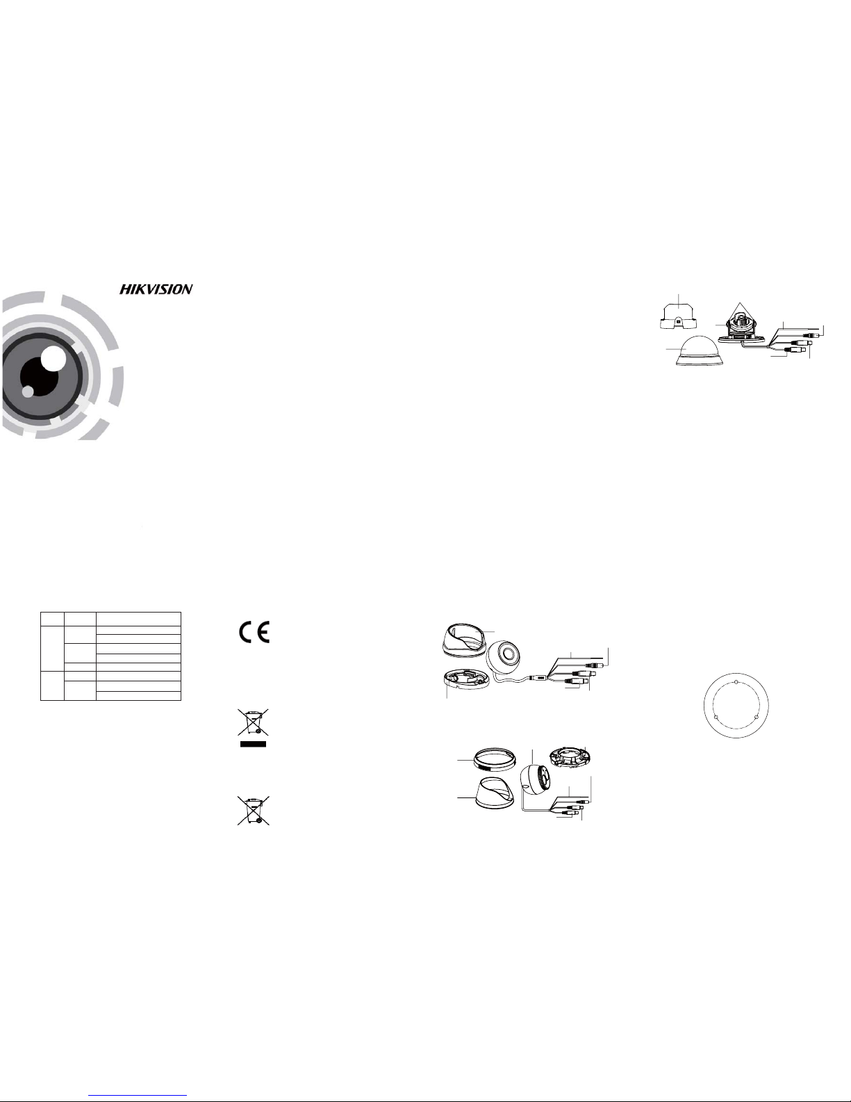
1.2 .1 Over view of Ty pe I Came ra
Lower
Dome
Black Liner
Camera
Lock Screw
TVI
Powe r Cable
Switch Cable
Mounting Base
Camera
Trim Ring
Enclosure
Analog Video Cable
Analog Video Cable
TVI
Powe r Cable
Switch Cable
1.2 .2 Over view of Ty pe Came ra
II
Enclosure
TVI
Analog Video Cable
Switch Cable
Powe r Cable
Mounting Base
1.2.3 Overview of Type CameraIII
2 Installation
Before you start:
l Ple ase mak e sure tha t the dev ice in th e packa ge
is in good condition and all the assembly parts
are i nclud ed.
l Mak e sure tha t all the r elated e quipm ent is
power-off during the installation.
l Check the specification of the products for the
installation environment.
l Che ck whet her the p ower su pply is m atched
wit h your po wer outp ut to avo id dama ge.
l Please make sure the wall is strong enough to
withstand three times the weight of the camera
and the mounting.
l If th e wall is t he ceme nt wall , you need t o inser t
exp ansio n screws b efore yo u instal l the cam era.
If the wall is the wooden wall, you can use
sel f-tap ping sc rew to sec ure the c amera.
l If the product does not function properly,
please contact your dealer or the nearest
ser vice ce nter. Do not d isass emble t he came ra
for repair or maintenance by yourself.
2.1 Installation of Type CameraI
Steps:
1.Dr ill the s crew ho les and t he cable h ole
according to the drill template.
Drilling Template
Screw Hole
Screw Hole
Screw Hole
Figure 2-1 The Drill Template
2.Fix the mounting base to the ceiling with the
supplied screws.
3.Ro ute the ca bles to t he cabl e hole an d connec t
the c orresp ondin g power c able an d video c able.
4.Secure the camera to the mounting base.
5.Fi x the enc losur e to camer a to compl et the
installation.
DS-2CE56C2T-IR
Page 2
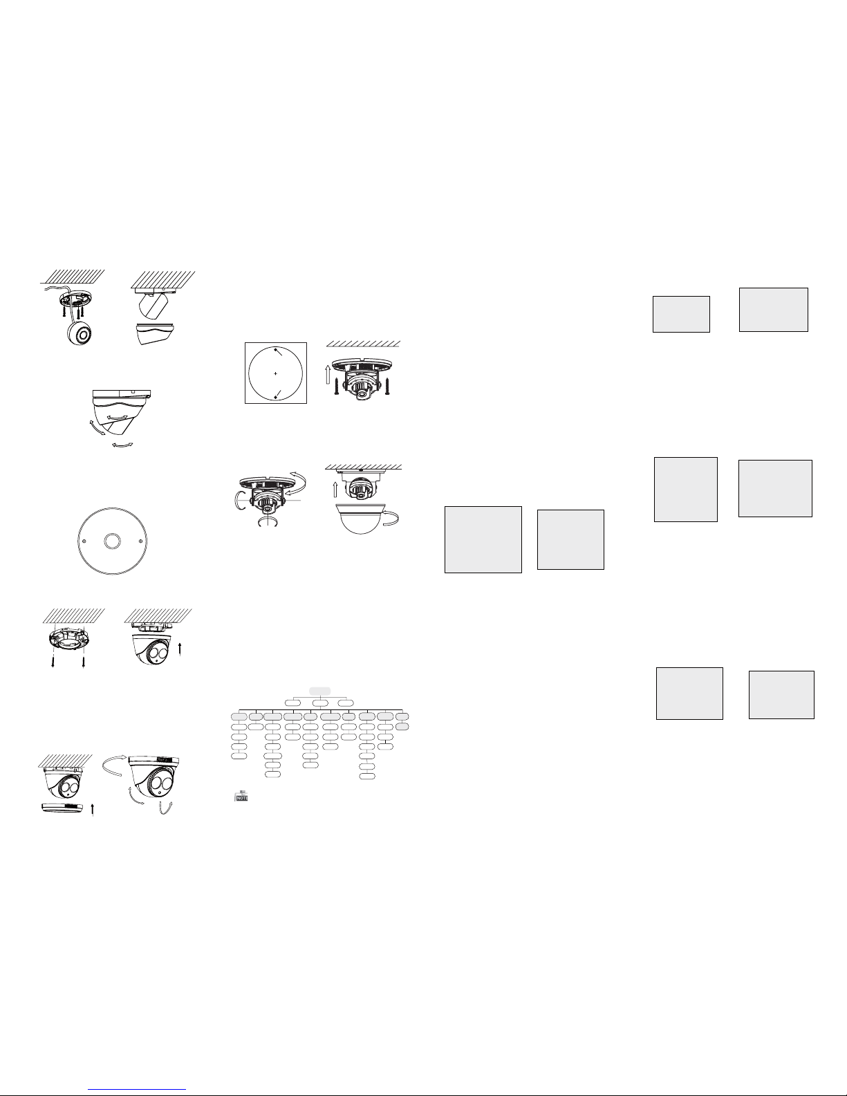
Fig ure 2-2 F ix the Mo unting B ase and t he Came ra
6.Ad just th e camera a ccord ing to the f igure b elow
to get a n optim um angl e.
Figure 2-3 3-axis Adjustment
0 ~360°°
0~75°°
0 ~360°°
2.2 Installation of Type CameraII
1.Dr ill the s crew ho les and t he cable h ole on th e
ceiling according to the supplied drill template.
Steps:
Figure 2-4 The Drill Template
Mounting Base
Hole
Hole
Fig ure 2-5 F ix the Mo unting B ase and C amera
2.Fix the mounting base to the ceiling with the
supplied screws.
3.Ro ute the ca bles to t he cabl e hole an d connec t
corresponding power cable and video cable.
4.Se cure th e camera t o the mou nting b ase.
5.Fi x the enc losur e to camer a.
6.A ttach th e trim ri ng to the ca mera an d rotate
it clockwise to secure the camera loosely.
0 ~360°°
0~75°°
0 ~360°°
Figure 2-6 3-axis Adjustment
2.3 Installation of Type CameraIII
1.H old the m ounti ng base , and rota te the lo wer
dome counterclockwise to disassemble the
low er dome a nd the bl ack lin er.
2.D rill th e screw ho les and t he cabl e hole on t he
ceiling according to the supplied drill template.
Steps:
Drilling Template
Screw Hole
Screw Hole
3.Route the cables to the cable hole and connect
the corresponding power cable and video cable.
4.Fix the mounting base to the ceiling with
the supplied screws.
5.Adjust the Lens
1).Loosen the tilting lock screws besides the
lens.
2).Adjust the camera from the pan angle
(0 ~ 355 ); tilt angle (0 ~ 90 ), and rotate°° °°
the l ens(0 ~ 355 ) to ge t the opt imum an gle.°°
3).Tighten the tilting lock screws.
355°
355°
0-90°
6.Fi t the bla ck line r back to t he camer a.
7.In stall th e lower d ome bac k to the ca mera and
rota te it clo ckwis e to get it se cured .
Fig ure 2-7 T he Dril l Templ ate & Mou nting
Base Installation
Figure 2-8 3-axis Adjustment
& Low er Dome
3 Menu Operation
Figure 3-1 Main Menu
Menu
SCENE
LENS
RESET
EXPOSURE
WB
DAY&NIGHT
BACKLIGHT
NR
SPECIAL
ADJUST
INDOOR
OUTDOOR
INDOOR1
LOWLIGHT
MANUAL
SHUTTER
AGC
SENS-UP
BRIGHTNESS
D-WDR
DEFOG
BLC
HSBLC
ATW
AWC-SET
INDOOR
OUTDOOR
MANUAL
COLOR
B/W
EXT
2DNR
3DNR
CAM
TITLE
D-EFFECT
MOTION
PRIVACY
LAUGUAGE
DEFECT
VERSION
SHARPNESS
MONITOR
LSC
VIDEO.
OUT
EXIT
SETUP
A coaxial camera controller (purchase separately)
is required to select the menu and adjust the
camera param eters.
3.1 VIDEO.OUT
PAL or NTSC is selectable .
3.2 LANGUAGE
Eng lish, J apane se, CHN 1, CHN2 , Korean , Germa n,
French, Italian, Spanish, Polish, etc., are selectable.
3.3SETUP
3.3.1 SCENE
You can select indoor, outdoor, indoor 1 and low
-li ght as th e worki ng envir onmen ts.
3.3.2 LENS
The c amera is e quipp ed with a f ixed le ns.
3.3.3 EXPOSURE
EXPOSURE
1. SHUTTER AUTO
2. AGC OFF
3. SENS-UP ---
4. BRIGHTNESS ---|------ 40
5. DEFOG OFF
6. BACKLIGHT OFF
7. RETURN RET
Figure 3-2 Exposure
SHUTTER: AUTO,1/25, 1/50, FLK, 1/200, 1/400,
1/1 k, 1/2k , 1/5k, 1 /10k, 1 /50k, x 2, x4, x6 , x8, x10 ,
and x15 are selectable.
: You can s et the AG C value fr om 0 to 15.AGC
: You can s et the SE NS-UP t o OFF or AUT O.SENS-UP
: You can s et the br ightn ess valu eBRIGHTNESS
fro m 1 to 100.
: You can s et the D- WDR to ON t o improv eD-WDR
the i mage qu ality o r OFF to dis able th e funct ion.
: You can s et the de fog func tion as O N toDEFOG
enable the function. Position, size, and the defog
gradation are configurable.
3.3.4 Backlight
Backlight Compensation (BLC):
Set t he gain of B LC as Hig h, Midd le, or Lo w.-GAIN:
Press the up/down/left/right button to-AREA:
define the BLC position and size. Select RET or
AGA IN to go bac k the BLC m enu or re -defi ne the
BLC a rea.
Rest ore the B LC setti ngs to th e defaul t.-Default:
HSBLC:
Select an HSBLC area. Set the DISPLAY status as ON.
Press the up/down/left/right button to define the
are a posit ion and s ize. Set t he HSBL C LEVEL f rom 0
to 100. Select ALL DAY or Night for the HSBLC mode.
Set t he BLAC K MASK sta tus as ON o r OFF.
HSBLC
1. SELECT AREA 1
2. DISPLAY ON 8
3. LEVEL ---|------ 40
4. MODE ALL DAY
5. BLACK MASK ON
6. DEFAULT 8
7. RETURN RET
Fig ure 3-3 H SBLC
3.3.5 White Balance (WB)
INDOOR, OUTDOOR, MANUAL, ATW (Auto-tracking
White Balance), AWC→SET are selectable.
3.3 .6 Day & Ni ght
Color, B/W, and EXT are selectable for DAY and
NIGHT switches.
3.3.7 NR
: You can s et 2D NR sta tus as ON o r OFF.2D NR
: Set the Smart NR status as ON and adjust3D NR
the 3 D smart N R sensi tivit y ranges f rom 0 to 10 0.
Set t he 3D NR LE VEL rang es from 0 t o 100. Set t he
2D&3D NR
1. 2DNR OFF
2. 3DNR ON
8
3. RETURN RET
3D NR
1. SMART NR ON
8
2. LEVEL ------|--8 0
3. START. AGC -|--------10
4. END. AGC -|--------10
5. RETURN RET
Fig ure 3-5 N R
Fig ure 3-6 3 D NR
3.3 .8 SPEC IAL
: Edi t the came ra titl e on this s ectio n.Camera Title
:D-effect
: Set t he freez e funct ion as ON o r OFF.-FREEZE
: OFF, MI RROR, V -FLIP, and R OTATE are-MIRROR
selectable for mirror.
: Def ine the zo om area b y confi gurin g-D-ZOOM
the p ositi on from PAN & T ILT.
: The D-Zoom area, sensitivity-SMART D-ZOOM
and time are configurable.
: Set t he NEG IM AGE as ON or O FF.-NEG.IMAGE
SPECIAL
1. CAM TITLE ON
8
2. D-DFFECT 8
3. MOTION OFF
4. PRIVACY OFF
5. LANGUAGE ENG
8
6. DEFECT 8
7. VERSION 130722
8. RETURN RET
Figure 3-7 Special
MOTION
1. SELECT AREA 1
2. DISPLAY ON8
3. SENSITIVITY ----|---- 30
4. MOTION VIEW ON
5. DEFAULT 8
6. RETURN RET
Fig ure 3-8 M otion D etecti on
Motion: Select a MOTION area. Set the DISPLAY
status as ON or OFF. Press the up/down/left/right
but ton to def ine the p ositi on and si ze of the a rea.
Set t he SENS ITIVI TY from 0 to 6 0. Set th e MOTIO N
VIE W status a s ON or OFF.
Privacy: Select a PRIVACY area. Set the DISPLAY
stat us as INV, MO SAIC, C OLOR or O FF. Pre ss the
up/down/left/right button to define the position
and s ize of the a rea.
Defect: LIVE D PC, STATIC D PC and Bl ack DPC a re
adjustable in this section.
: You can c heck th e softw are vers ion of th eVersion
device.
PRIVACY
1. SELECT AREA 1
2. DISPLAY MOSAIC
8
3. COLOR 10
4. TRANS. 1
5. DEFAULT
8
6. RETURN RET
ADJUST
1. SHARPNESS
--------|15
2. MONITOR LCD8
3. LSC OFF
4. VIDEO. OUT PAL
5. RETURN RET
3.3.9 ADJUST
: Adjust the sharpness from 0 to 15.Sharpness
: Monitor CRT, and Monitor LCD areMonitor
selectable.
: Set t he LSC sta tus as ON o r OFF.LSC
3.3.10 RESET
Res et all the s ettin gs to the d efault .
3.3.11 EXIT
Pre ss OK to exi t the men u.
START. AGC l evel as t he thre shold t o enabl e AGC,
and s et the EN D. AGC lev el as the t hresho ld to
disable AGC.
Figure 3-9 Privacy Mask
Figure 3-10 Adjust
 Loading...