

Page 1

Network Camera
Quick Operation Guide
V4.0.1
Hikvision Digital Technology Co., Ltd.
http://www.hikvision.com
Page 2

Quick Operation Guide of Network Camera
1
Type
Model
Box camera III
DS-2CD883F-E, DS-2CD855F-E, DS-2CD854F(WD)-E,
DS-2CD853F-E, DS-2CD864F(WD)-E,
DS-2CD863PF(NF)-E, DS-2CD893PFWD(NFWD)-E,
DS-2CD833F-E, DS-2CD893PF(NF)-E
Dome camera III
DS-2CD783F-E(I), DS-2CD754F-E(I), DS-2CD764FWD-E(I),
DS-2CD764F-E, DS-2CD754FWD-E(I), DS-2CD753F-E(I),
DS-2CD763PF(NF)-E(I), DS-2CD793PF-E(I),
DS-2CD793PFWD(NFWD)-E(I), DS-2CD733F-E(I),
DS-2CD733F-EZ, DS-2CD755F-E(I), DS-2CD793NF-E(I)
Dome camera IV
DS-2CD7233F-EIZH, DS-2CD7253F-E(I)ZH,
DS-CD7254F-EIZH, DS-2CD7293PFWD(NFWD)-EIZH,
DS-2CD7263NF(PF)-EZH, DS-2CD 7264FWD-EZH,
DS-2CD7293PF(NF)-EIZH, DS-2CD7255F-EIZHS
Bullet Camera
DS-2CD8253F-EI(Z), DS-2CD8233F-EI(Z),
DS-2CD8264FWD-EI(Z), DS-2CD8264F-E,
DS-2CD8254F-EI, DS-2CD8254FWD-E, DS-2CD8283F-EI,
DS-2CD8255F-EI
Cube Camera I
DS-2CD8133F-E, DS-2CD8153F-E
Cube Camera II
DS-2CD8464F-EI, DS-2CD8433F-EI
Mini Dome Camera
DS-2CD7164-E,DS-2CD7153-E, DS-2CD7133-E
Thank you for purchasing our product. If there are any questions, or requests, please do not hesitate
to contact the dealer. This manual applies to
© Hikvision Digital Technology Co., Ltd. All Rights Reserved.
Page 3

Quick Operation Guide of Network Camera
2
This manual may contain several technical incorrect places or printing errors, and the content is
subject to change without notice. The updates will be added to the new version of this manual. We
will readily improve or update the products or procedures described in the manual.
DISCLAIMER STATEMENT
“Underwriters Laboratories Inc. (“UL”) has not tested the performance or reliability of the security
or signaling aspects of this product. UL has only tested for fire, shock or casualty hazards as
outlined in UL’s Standard(s) for Safety, UL60950-1. UL Certification does not cover the
performance or reliability of the security or signaling aspects of this product. UL MAKES NO
REPRESENTATIONS, WARRANTIES OR CERTIFICATIONS WHATSOEVER REGARDING THE
PERFORMANCE OR RELIABILITY OF ANY SECURITY OR SIGNALING RELATED FUNCTIONS OF THIS
PRODUCT.”
© Hikvision Digital Technology Co., Ltd. All Rights Reserved.
Page 4

Quick Operation Guide of Network Camera
3
Table of Contents
Chapter 1 Appearance Description .......................................................................... 1
1.1 Appearance Description of Box Camera ........................................................... 1
1.1.1 Box Camera I ................................................................................................. 1
1.1.2 Box Camera II ................................................................................................ 2
1.1.3 Box Camera III ............................................................................................... 5
1.2 Appearance Description of Dome Camera ........................................................ 7
1.2.4 Dome Camera I .............................................................................................. 7
1.2.5 Dome Camera II ............................................................................................. 8
1.2.6 Dome Camera III .......................................................................................... 10
1.2.7 Dome Camera IV ......................................................................................... 12
1.3 Appearance Description of Bullet Camera ...................................................... 13
1.4 Appearance Description of Cube Camera ....................................................... 14
1.4.1 Cube Camera I ............................................................................................. 14
1.4.2 Cube Camera II ............................................................................................ 15
1.5 Appearance Description of Mini Dome Camera .............................................. 18
Chapter 2 Setting up the Network Camera over the LAN ....................................... 20
Chapter 3 Accessing via Web Browsers ................................................................. 23
© Hikvision Digital Technology Co., Ltd. All Rights Reserved.
Page 5
Quick Operation Guide of Network Camera
1
No.
Description
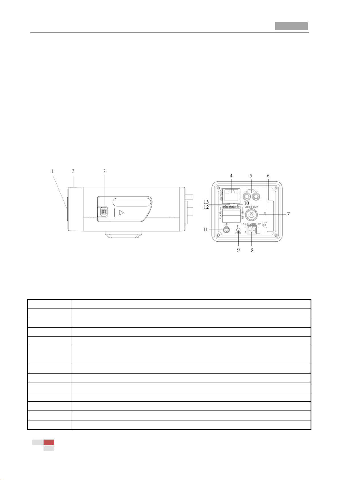
1
CS Lens mount
2
Back focus ring
3
Auto-iris interface
4
10M/100M self-adaptive Ethernet interface
5
AUDIO IN: Audio input interface
AUDIO OUT: Audio output interface
6
SD: SD card slot
7
VIDEO OUT: Video output interface
8
Power supply interface
9
PWR: Power LED indicator
10
D+, D-: RS-485 interface
11
Ground
12
1A, 1B: Alarm output interface
Chapter 1 Appearance Description
There are ten physical structures of network cameras, Box camera I, Box camera II, Box camera III,
Dome camera I, Dome camera II, Dome camera III, Dome camera IV, Bullet Camera, Cube Camera
and Mini Dome Camera.
1.1 Appearance Description of Box Camera
1.1.1 Box Camera I
Camera description:
Figure 1-1 Overview
Table 1-1 Description
© Hikvision Digital Technology Co., Ltd. All Rights Reserved.
Page 6
Quick Operation Guide of Network Camera
2
13
IN, G: Alarm input interface
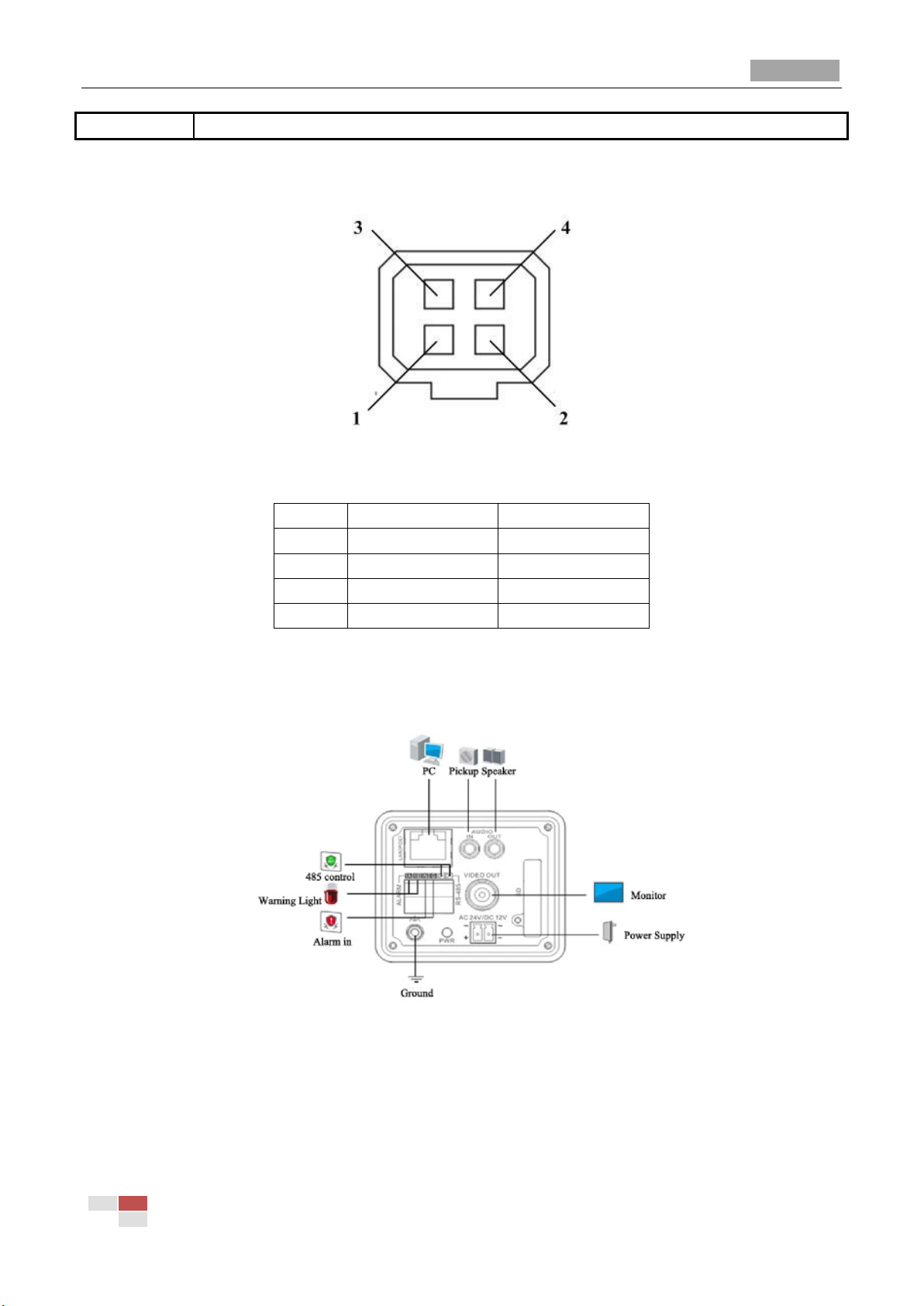
Video-driven
DC-driven
1
Power
Damp-
2
NC
Damp+
3
Video
Drive+
4
GND
Drive-
Note: The type of auto-iris interface is shown in Figure 1-2, and the definition of each pin is shown
below:
Figure 1-2 Auto-iris Interface
Table 1-2 Pins
Power, Video and GND pins are used when the auto-iris is driven by video; Damp+, Damp-, Drive+
and Drive- pins are used when the auto-iris is driven by DC.
Camera wiring Diagram:
Figure 1-3 Wiring Diagram
1.1.2 Box Camera II
Camera description:
© Hikvision Digital Technology Co., Ltd. All Rights Reserved.
Page 7
Quick Operation Guide of Network Camera
3
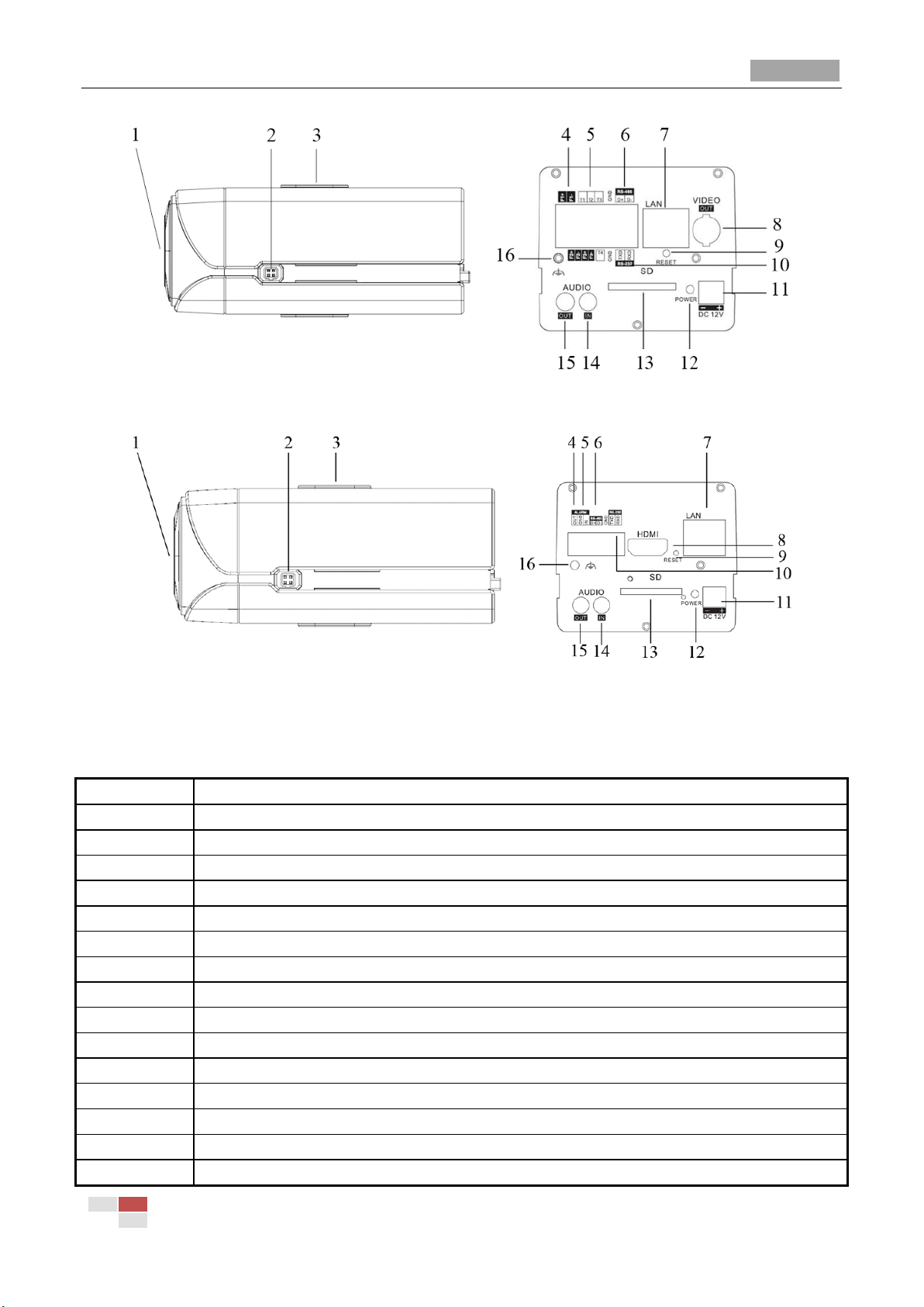
No.
Description
1
CS Lens mount
2
Auto-iris interface
3
Bracket mounting holes
4
F1+ F1-, F2+ F2- ,F3+ F3-: Alarm output interface
5
T1,T2,T3, T4,GND: Alarm input interface
6
D+, D-: RS-485 interface
7
10M/100M self-adaptive Ethernet interface
8
VIDEO OUT/HDMI: Video output interface
9
RESET: Reset button
10
TXD, RXD, GND: RS-232 interface
11
Power supply interface
12
POWER: Power LED indicator
13
SD: SD card slot
14
AUDIO IN: Audio input interface
15
AUDIO OUT: Audio output interface
Figure 1-4 Overview
Figure 1-5 Overview
Table 1-3 Description
© Hikvision Digital Technology Co., Ltd. All Rights Reserved.
Page 8
Quick Operation Guide of Network Camera
4
16
Ground
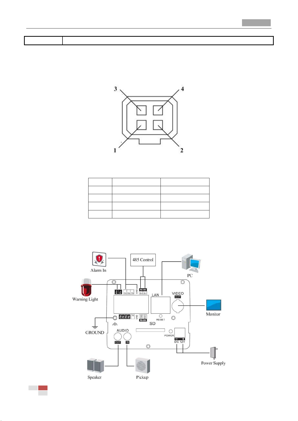
Video-driven
DC-driven
1
Power
Damp-
2
NC
Damp+
3
Video
Drive+
4
GND
Drive-
Notes:
After the powering on of the camera, pressing and holding the RESET button for about 10
seconds can reset all the parameters to the default settings.
The type of auto-iris interface is shown in Figure 1-6, and the definition of each pin is shown
below:
Figure 1-6 Auto-iris Interface
Table 1-4 Pins
Power, Video and GND pins are used when the auto-iris is driven by video; Damp+, Damp-, Drive+
and Drive- pins are used when the auto-iris is driven by DC.
Camera wiring Diagram:
© Hikvision Digital Technology Co., Ltd. All Rights Reserved.
Page 9
Quick Operation Guide of Network Camera
5
No.
Description
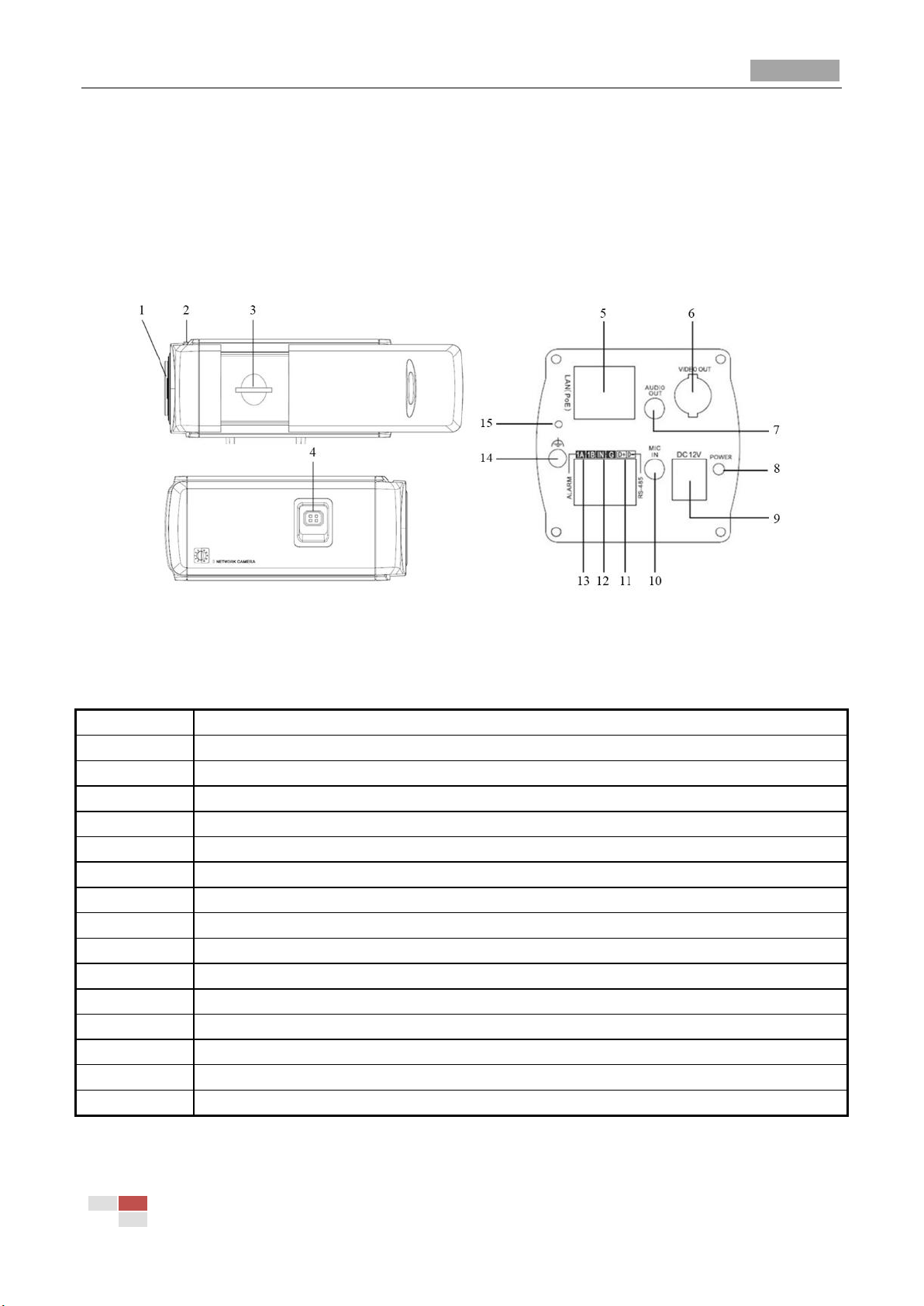
1
Lens mount
2
Back focus ring
3
SD card slot
4
Auto-iris interface
5
10M/100M self-adaptive Ethernet interface
6
VIDEO OUT: Video output interface
7
AUDIO OUT: Audio output interface
8
POWER: Power LED indicator
9
Power supply interface
10
MIC IN: Audio input interface
11
D+, D-: RS-485 interface
12
IN, G: Alarm input interface
13
1A, 1B: Alarm output interface
14
Ground
15
RESET: Reset button
1.1.3 Box Camera III
Camera description:
Figure 1-7 Wiring Diagram
Figure 1-8 Overview
Table 1-5 Description
Notes:
After the powering on of the camera, pressing and holding the RESET button for about 10
© Hikvision Digital Technology Co., Ltd. All Rights Reserved.
Page 10

Quick Operation Guide of Network Camera
6
Video-driven
DC-driven
1
Power
Damp-
2
NC
Damp+
3
Video
Drive+
4
GND
Drive-
seconds can reset all the parameters to the default settings.
The type of auto-iris interface is shown in Figure 1-9, and the definition of each pin is shown
below:
Figure 1-9 Auto-iris Interface
Table 1-6 Pins
Power, Video and GND pins are used when the auto-iris is driven by video; Damp+, Damp-, Drive+
and Drive- pins are used when the auto-iris is driven by DC.
Camera wiring Diagram:
© Hikvision Digital Technology Co., Ltd. All Rights Reserved.
Page 11

Quick Operation Guide of Network Camera
7
No.
Description
1
Video output interface
2
Power LED indicator
3
DIP switch
4
10M/100M self-adaptive Ethernet interface
5
D+, D-: RS-485 interface
6
Alarm IN: Alarm input interface
Alarm OUT: Alarm output interface
7
AIN: Audio input interface
AOUT: Audio output interface
8
Power supply interface
Position
Function
ON
OFF
Figure 1-10 Wiring Diagram
1.2 Appearance Description of Dome Camera
1.2.1 Dome Camera I
Camera description:
Figure 1-11 Overview
Table 1-7 Description
The function of positions 1-5 of DIP switch is shown below:
© Hikvision Digital Technology Co., Ltd. All Rights Reserved.
Page 12

Quick Operation Guide of Network Camera
8
1
SHARP: Sharpness
SOFT
2
AES: Auto Shutter
AI: Auto Iris
3
BLC: Back Light Compensation
OFF
4
FL: Anti-flicker
ON 5 NAGC: Normal AGC
SAGC: Special AGC
Camera wiring Diagram:
1.2.2 Dome Camera II
Camera description:
Figure 1-12 Wiring Diagram
© Hikvision Digital Technology Co., Ltd. All Rights Reserved.
Page 13

Quick Operation Guide of Network Camera
9
No.
Description
1
10M/100M self-adaptive Ethernet interface
2
AUDIO IN: Audio input interface
3
AUDIO OUT: Audio output interface
4
D+, D-: RS-485 interface
5
IN, G: Alarm input interface
1A, 1B: Alarm output interface
6
Power supply interface
Figure 1-13 Overview
Camera wiring Diagram:
Table 1-8 Description
Figure 1-14 Wiring Diagram
© Hikvision Digital Technology Co., Ltd. All Rights Reserved.
Page 14

Quick Operation Guide of Network Camera
10
No.
Description
1
10M/100M self-adaptive Ethernet interface
2
INITIAL SET: Reset button
3
AUDIO OUT: Audio output interface
4
MIC IN: Audio input interface
5
D+, D-: RS-485 interface
6
1A, 1B, 2A, 2B: Alarm output interface
7
IN1, GND, IN2, GND: Alarm input interface
8
Power supply interface
1.2.3 Dome Camera III
Camera description:
Figure 1-15 Overview
Table 1-9 Description
Note: After the powering on of the camera, pressing and holding the INITIAL SET button for about
10 seconds can reset all the parameters to the default settings.
Camera wiring Diagram:
© Hikvision Digital Technology Co., Ltd. All Rights Reserved.
Page 15

Quick Operation Guide of Network Camera
11
Figure 1-16 Wiring Diagram
© Hikvision Digital Technology Co., Ltd. All Rights Reserved.
Page 16

Quick Operation Guide of Network Camera
12
No.
Description
1
Video output interface
2
LINK: Indicator is solid yellow when network is connected.
3
ACT: Indicator flashes blue when network connection is functioning properly.
4
PWR: Indicator is solid red when the device is powered on.
5
Micro SD slot
6
RESET: Reset button
7
10M/100M self-adaptive Ethernet interface
8
Power supply interface
9
Extended interface
7
8
9
1.2.4 Dome Camera IV
Camera description:
Figure 1-17 Overview
Table 1-10 Description
Notes:
The extended interface can be connected to alarm input/output interface, audio input/output
© Hikvision Digital Technology Co., Ltd. All Rights Reserved.
Page 17

Quick Operation Guide of Network Camera
13
No.
Description
interface, RS-485 interface, etc.
After the powering on of the camera, pressing and holding the RESET button for about 10
seconds can reset all the parameters to the default settings.
Camera wiring Diagram:
Figure 1-18 Wiring Diagram
1.3 Appearance Description of Bullet Camera
Camera description:
Figure 1-19 Overview
Figure 1-20 Overview
Table 1-11 Description
© Hikvision Digital Technology Co., Ltd. All Rights Reserved.
Page 18

Quick Operation Guide of Network Camera
14
1
10M/100M self-adaptive Ethernet interface
2
Power supply interface
3
IN, G: Alarm input interface
1A, 1B: Alarm output interface
4
D+, D-: RS-485 interface
5
AUDIO IN, G: Audio input interface
AUDIO OUT, G: Audio output interface
1 2 4
5
3
6
7
8
9
10
11
Camera wiring Diagram:
Figure 1-21 Wiring Diagram
1.4 Appearance Description of Cube Camera
1.4.1 Cube Camera I
Camera description:
Figure 1-22 Overview
© Hikvision Digital Technology Co., Ltd. All Rights Reserved.
Page 19

Quick Operation Guide of Network Camera
15
No.
Description
1
Microphone
2
Infrared light (Optional)
3
Micro SD card slot
4
LINK: Network status LED indicator.
LED indicator is solid yellow when network connection is functioning
properly.
5
Power LED indicator, It is solid red when power is applied to the unit.
6
Lens
7
ETHERNET: 10M / 100M self-adaptive Ethernet interface
8
RESET: Reset button
9
Speaker
10
Power supply interface
11
Screw hole, used to fix the camera to the bracket
Table 1-12 Description
Note:
After the powering on of the camera, pressing and holding the RESET button for about 10 seconds
can reset all the parameters to the default settings.
Camera wiring Diagram:
Figure 1-23 Wiring Diagram
1.4.2 Cube Camera II
Camera description:
© Hikvision Digital Technology Co., Ltd. All Rights Reserved.
Page 20

Quick Operation Guide of Network Camera
16
No.
Description
1
Photosensitive resistance
2
Infrared light
3
PIR sensor
4
Microphone
5
Lens
6
Alarm: Indicator is solid red when the camera is armed with PIR and
access control and it is solid blue when the camera is unarmed.
7
Indicator flashes blue when movement or presence is detected in
its field of view.
8
Link: Indicator flashes orange when network connection is
functioning properly.
9
Tri-axial adjustment bracket
10
USB interface
11
Battery
12
Speaker
13
RESET: Reset button
14
Micro SD card slot
15
Power supply interface
16
10M / 100M self-adaptive Ethernet interface & PoE
1
2
3
4 6 7
8
5
9
10
11
12
13
14
16
15
Figure 1-24 Overview
Table 1-13 Description
Note:
After the powering on of the camera, pressing and holding the RESET button for about 10 seconds
can reset all the parameters to the default settings.
Camera wiring diagram:
© Hikvision Digital Technology Co., Ltd. All Rights Reserved.
Page 21

Quick Operation Guide of Network Camera
17
Figure 1-25 Wiring Diagram
© Hikvision Digital Technology Co., Ltd. All Rights Reserved.
Page 22

Quick Operation Guide of Network Camera
18
No.
Description
1
Cover
2
Lens
3
P: Power LED indicator, It is solid red when power is applied to the unit.
4
Base plate
5
Set screw hole
6
Set screw of lens
7
S & L: Network status LED indicator.
When the network is connected, the “S” LED is solid yellow, while the “L” LED
flashes orange.
8
RESET: Reset button.
1.5 Appearance Description of Mini Dome Camera
Camera description:
Figure 1-26 Overview
Table 1-14 Description
Note:
After the powering on of the camera, pressing and holding the RESET button for about 10 seconds
can reset all the parameters to the default settings.
Camera wiring Diagram:
© Hikvision Digital Technology Co., Ltd. All Rights Reserved.
Page 23

Quick Operation Guide of Network Camera
19
Figure 1-27 Wiring Diagram
© Hikvision Digital Technology Co., Ltd. All Rights Reserved.
Page 24

Quick Operation Guide of Network Camera
20
Chapter 2 Setting the Network Camera over
the LAN
Purpose:
To view and configure the camera via LAN (Local Area Network), you need to connect the network
camera in the same subnet with your PC. Then install the SADP or iVMS-4200 software to search
and change the IP of network camera.
The following figure shows the cable connection of a network camera and a PC:
Figure 2-1 Wiring over LAN
Set the IP address of the camera for accessing via LAN.
Steps:
1. To get the IP address, you can choose either of the following methods:
Use SADP, a software tool which can automatically detect network camera in the LAN and
list the device information like IP address, subnet mask, port number, device serial number,
device version, etc., shown in Figure 2-2.
Use iVMS-4200 software and to list the online devices. Please refer to the user manual of
client software for detailed information.
2. Change the IP address and subnet mask to the same subnet as of your PC.
Refer to the following introduction to set IP address with SADP software:
Search active devices online
Search online devices automatically:
After launch the SADP software, it automatically searches the online devices every 15
seconds from the subnet where your computer locates. It displays the total number
© Hikvision Digital Technology Co., Ltd. All Rights Reserved.
Page 25

Quick Operation Guide of Network Camera
21
and information of the searched devices in the Online Devices interface. Device
information including the device type, IP address, port number, gateway, etc. will be
displayed.
Figure 2-2 Searching Online Devices
Note: Device can be searched and displayed in the list in 15 seconds after it goes online;
it will be removed from the list in 45 seconds after it goes offline.
Search online devices manually:
You can also click to refresh the online device list manually. The newly
searched devices will be added to the list.
Note: You can click or on each column heading to order the information; you
can click to show the device table and hide the network parameter panel on the
right side, or click to show the network parameter panel.
Modify device information
Steps:
1) Select the device to be modified in the device list and the network parameters of the
© Hikvision Digital Technology Co., Ltd. All Rights Reserved.
Page 26

Quick Operation Guide of Network Camera
22
device will be displayed in the Modify Network Parameters panel on the right side.
2) Edit the modifiable network parameters, e.g. IP address and port number.
3) Enter the password of the admin account of the device in the Password field and click
to save the changes.
Figure 2-3 Modify Network Parameters
3. You can enter the IP address of network camera in the address field of the web browser to view
the live video.
Note:
The default value of the IP address is “192.0.0.64”. The default user name is “admin”, and
password is “12345”.
For accessing the network camera from different subnets, please set the gateway for the
network camera after you log in.
© Hikvision Digital Technology Co., Ltd. All Rights Reserved.
Page 27

Quick Operation Guide of Network Camera
23
Chapter 3 Accessing via Web Browsers
System Requirement:
Operating System: Microsoft Windows XP SP1 and above version / Vista / Win7 / Server 2003 /
Server 2008 32bits
CPU: Intel Pentium IV 3.0 GHz or higher
RAM: 1G or higher
Display: 1024×768 resolution or higher
Web Browser: Internet Explorer 6.0 and above version, Apple Safari 5.02 and above version, Mozilla
Firefox 3.5 and above version and Google Chrome8 and above version
Before you start:
Check the security level of the web browser and change it to Low.
On the IE browser menu bar, navigate to Tools > Internet options > Security > Custom level to
customize the level to LOW.
Figure 3-1 Adjust the Security Level
Steps:
1. Open the web browser.
2. In the browser address bar, input the IP address of the network camera, e.g., 192.0.0.64 and
press the Enter key to enter the login interface.
3. Input the user name and password.
4. Click .
© Hikvision Digital Technology Co., Ltd. All Rights Reserved.
Page 28

Quick Operation Guide of Network Camera
24
Figure 3-2 Login Interface
5. Install the plug-in before viewing the live video and managing the camera. Please follow the
installation prompts to install the plug-in.
Note: You may have to close the web browser to finish the installation of the plug-in.
Figure 3-3 Download Plug-in
© Hikvision Digital Technology Co., Ltd. All Rights Reserved.
Page 29

Quick Operation Guide of Network Camera
25
Figure 3-4 Download Plug-in
Figure 3-5 Install Plug-in
Figure 3-6 Install Plug-in
6. Reopen the web browser after the installation of the plug-in and repeat the above steps 2-4 to
login.
Note: For detailed instructions of further configuration, please refer to the user manual of network
camera.
© Hikvision Digital Technology Co., Ltd. All Rights Reserved.
Page 30

First Choice for Security Professionals
 Loading...