

Page 1

Network Camera User Manual
0
User Manual
UD16429B
Network Camera
Page 2

Network Camera User Manual
1
User Manual
© 2019 Hangzhou Hikvision Digital Technology Co., Ltd. All rights reserved.
This Manual is the property of Hangzhou Hikvision Digital Technology Co., Ltd. or its
affiliates (hereinafter referred to as "Hikvision"), and it cannot be reproduced,
changed, translated, or distributed, partially or wholly, by any means, without the
prior written permission of Hikvision. Unless otherwise expressly stated herein,
Hikvision does not make any warranties, guarantees or representations, express or
implied, regarding to the Manual, any information contained herein.
About this Manual
The Manual includes instructions for using and managing the Product. Pictures,
charts, images and all other information hereinafter are for description and
explanation only. The information contained in the Manual is subject to change,
without notice, due to firmware updates or other reasons. Please find the latest
version of this Manual at the Hikvision website (http://www.hikvision.com/en/).
Please use this Manual with the guidance and assistance of professionals trained in
supporting the Product.
Trademarks Acknowledgement
and other Hikvision’s trademarks and logos are the properties of
Hikvision in various jurisdictions.
Other trademarks and logos mentioned are the properties of their respective
owners.
The terms HDMI and HDMI High-Definition Multimedia Interface, and
the HDMI Logo are trademarks or registered trademarks of HDMI Licensing
Administrator, Inc. in the United States and other countries.
LEGAL DISCLAIMER
TO THE MAXIMUM EXTENT PERMITTED BY APPLICABLE LAW, THIS MANUAL AND
Page 3

Network Camera User Manual
2
THE PRODUCT DESCRIBED, WITH ITS HARDWARE, SOFTWARE AND FIRMWARE, ARE
PROVIDED "AS IS" AND "WITH ALL FAULTS AND ERRORS". HIKVISION MAKES NO
WARRANTIES, EXPRESS OR IMPLIED, INCLUDING WITHOUT LIMITATION,
MERCHANTABILITY, SATISFACTORY QUALITY, OR FITNESS FOR A PARTICULAR
PURPOSE. THE USE OF THE PRODUCT BY YOU IS AT YOUR OWN RISK. IN NO EVENT
WILL HIKVISION BE LIABLE TO YOU FOR ANY SPECIAL, CONSEQUENTIAL, INCIDENTAL,
OR INDIRECT DAMAGES, INCLUDING, AMONG OTHERS, DAMAGES FOR LOSS OF
BUSINESS PROFITS, BUSINESS INTERRUPTION, OR LOSS OF DATA, CORRUPTION OF
SYSTEMS, OR LOSS OF DOCUMENTATION, WHETHER BASED ON BREACH OF
CONTRACT, TORT (INCLUDING NEGLIGENCE), PRODUCT LIABILITY, OR OTHERWISE,
IN CONNECTION WITH THE USE OF THE PRODUCT, EVEN IF HIKVISION HAS BEEN
ADVISED OF THE POSSIBILITY OF SUCH DAMAGES OR LOSS.
YOU ACKNOWLEDGE THAT THE NATURE OF INTERNET PROVIDES FOR INHERENT
SECURITY RISKS, AND HIKVISION SHALL NOT TAKE ANY RESPONSIBILITIES FOR
ABNORMAL OPERATION, PRIVACY LEAKAGE OR OTHER DAMAGES RESULTING FROM
CYBER-ATTACK, HACKER ATTACK, VIRUS INSPECTION, OR OTHER INTERNET SECURITY
RISKS; HOWEVER, HIKVISION WILL PROVIDE TIMELY TECHNICAL SUPPORT IF
REQUIRED.
YOU AGREE TO USE THIS PRODUCT IN COMPLIANCE WITH ALL APPLICABLE LAWS,
AND YOU ARE SOLELY RESPONSIBLE FOR ENSURING THAT YOUR USE CONFORMS TO
THE APPLICABLE LAW. ESPECIALLY, YOU ARE RESPONSIBLE, FOR USING THIS
PRODUCT IN A MANNER THAT DOES NOT INFRINGE ON THE RIGHTS OF THIRD
PARTIES, INCLUDING WITHOUT LIMITATION, RIGHTS OF PUBLICITY, INTELLECTUAL
PROPERTY RIGHTS, OR DATA PROTECTION AND OTHER PRIVACY RIGHTS. YOU SHALL
NOT USE THIS PRODUCT FOR ANY PROHIBITED END-USES, INCLUDING THE
DEVELOPMENT OR PRODUCTION OF WEAPONS OF MASS DESTRUCTION, THE
DEVELOPMENT OR PRODUCTION OF CHEMICAL OR BIOLOGICAL WEAPONS, ANY
ACTIVITIES IN THE CONTEXT RELATED TO ANY NUCLEAR EXPLOSIVE OR UNSAFE
NUCLEAR FUEL-CYCLE, OR IN SUPPORT OF HUMAN RIGHTS ABUSES.
IN THE EVENT OF ANY CONFLICTS BETWEEN THIS MANUAL AND THE APPLICABLE
Page 4
Network Camera User Manual
3
LAW, THE LATER PREVAILS.
Safety Instruction
These instructions are intended to ensure that the user can use the product correctly
to avoid danger or property loss.
The precaution measure is divided into "Warnings" and "Cautions":
Warnings: Serious injury or death may be caused if any of these warnings are
neglected.
Cautions: Injury or equipment damage may be caused if any of these cautions are
neglected.
Warnings Follow these safeguards to
prevent serious injury or death.
Cautions Follow these precautions to
prevent potential injury or material
damage.
Warnings:
If camera fails to synchronize local time with that of the network, you need to set
up camera time manually. Visit the camera and enter system settings interface for
time setting.
Please adopt the power adapter which can meet the safety extra low voltage
(SELV) standard. And source with 12 VDC or 24 VAC (depending on models)
according to the IEC60950-1 and Limited Power Source standard.
To reduce the risk of fire or electrical shock, do not expose this product to rain or
moisture.
This installation should be made by a qualified service person and should
conform to all the local codes.
Please install blackouts equipment into the power supply circuit for convenient
Page 5

Network Camera User Manual
4
supply interruption.
Please make sure that the ceiling can support more than 50(N) Newton gravities
if the camera is fixed to the ceiling.
If the product does not work properly, please contact your dealer or the nearest
service center. Never attempt to disassemble the camera yourself. (We shall not
assume any responsibility for problems caused by unauthorized repair or
maintenance.)
Cautions:
Make sure the power supply voltage is correct before using the camera.
Do not drop the camera or subject it to physical shock.
Do not touch sensor modules with fingers. If cleaning is necessary, use a clean
cloth with a bit of ethanol and wipe it gently. If the camera will not be used for
an extended period of time, put on the lens cap to protect the sensor from dirt.
Do not aim the camera lens at the strong light such as sun or incandescent lamp.
The strong light can cause fatal damage to the camera.
The sensor may be burned out by a laser beam, so when any laser equipment is
being used, make sure that the surface of the sensor not be exposed to the laser
beam.
Do not place the camera in extremely hot, cold temperatures (refer to product
specification for working temperature), dusty or damp environment, and do not
expose it to high electromagnetic radiation.
To avoid heat accumulation, ensure there is good ventilation to the device.
Keep the camera away from water and any liquids.
While shipping, pack the camera in its original, or equivalent, packing materials.
Or packing the same texture.
Improper use or replacement of the battery may result in hazard of explosion.
Please use the manufacturer recommended battery type.
Notes:
Page 6

Network Camera User Manual
5
For the camera supports IR, you are required to pay attention to the following
precautions to prevent IR reflection:
Dust or grease on the dome cover will cause IR reflection. Please do not remove
the dome cover film until the installation is finished. If there is dust or grease on
the dome cover, clean the dome cover with clean soft cloth and isopropyl
alcohol.
Make certain the installation location does not have reflective surfaces of objects
too close to the camera. The IR light from the camera may reflect back into the
lens causing reflection.
The foam ring around the lens must be seated flush against the inner surface of
the bubble to isolate the lens from the IR LEDS. Fasten the dome cover to
camera body so that the foam ring and the dome cover are attached seamlessly.
Page 7

Network Camera User Manual
6
Table of Contents
System Requirement .............................................................................. 10
Network Connection .............................................................................. 11
Setting the Network Camera over the LAN ...................................................... 11
2.1.1 Wiring over the LAN........................................................................................................ 11
2.1.2 Activating the Camera .................................................................................................... 12
2.1.3 (Optional) Setting Security Question .............................................................................. 19
Setting the Network Camera over the WAN .................................................... 19
Static IP Connection ........................................................................................................ 19
2.2.2 Dynamic IP Connection ................................................................................................... 20
Access to the Network Camera ............................................................. 23
Accessing by Web Browsers ............................................................................ 23
Accessing by Client Software .......................................................................... 24
Wi-Fi Settings ......................................................................................... 26
Configuring Wi-Fi Connection in Manage and Ad-hoc Modes ........................... 26
Easy Wi-Fi Connection with WPS function ....................................................... 31
IP Property Settings for Wireless Network Connection .................................... 34
Live View ................................................................................................ 35
Live View Page ............................................................................................... 35
Live Operation ............................................................................................... 36
Recording and Capturing Pictures Manually .................................................... 37
Quick Setup ................................................................................................... 38
5.4.1 Operating PTZ Control .................................................................................................... 38
5.4.2 General Settings .............................................................................................................. 41
5.4.3 VCA Resource .................................................................................................................. 42
Install Plug-in ................................................................................................. 42
Network Camera Configuration ........................................................... 44
Configuring Local Parameters ......................................................................... 44
Configure System Settings .............................................................................. 46
6.2.1 Configuring Basic Information ........................................................................................ 46
6.2.2 Configuring Time Settings ............................................................................................... 46
6.2.3 Configuring RS-232 Settings ............................................................................................ 48
6.2.4 Configuring RS-485 Settings ............................................................................................ 49
6.2.5 Configuring DST Settings ................................................................................................. 50
6.2.6 Configuring External Devices .......................................................................................... 51
Page 8

Network Camera User Manual
7
6.2.7 Configuring VCA Resource .............................................................................................. 52
6.2.8 Configuring Metadata Settings ....................................................................................... 52
6.2.9 Open Source Software License ....................................................................................... 53
Maintenance ................................................................................................. 53
Upgrade & Maintenance ................................................................................................ 53
6.3.2 Log .................................................................................................................................. 55
6.3.3 System Service ................................................................................................................ 56
6.3.4 Security Audit Log ........................................................................................................... 57
Security Settings ............................................................................................ 59
Authentication ................................................................................................................ 59
6.4.2 IP Address Filter .............................................................................................................. 59
6.4.3 Security Service............................................................................................................... 61
6.4.4 Advanced Security .......................................................................................................... 62
6.4.5 Certificate Management ................................................................................................. 62
User Management ......................................................................................... 65
User Management .......................................................................................................... 65
6.5.2 Security Question ........................................................................................................... 67
Online Users .................................................................................................................... 69
Network Settings .................................................................................... 70
Configuring Basic Settings .............................................................................. 70
7.1.1 Configuring TCP/IP Settings ............................................................................................ 70
7.1.2 Configuring DDNS Settings .............................................................................................. 72
7.1.3 Configuring PPPoE Settings ............................................................................................. 74
7.1.4 Configuring Port Settings ................................................................................................ 74
7.1.5 Configure NAT (Network Address Translation) Settings .................................................. 76
7.1.6 Configuring Multicast ..................................................................................................... 77
Configure Advanced Settings .......................................................................... 78
Configuring SNMP Settings ............................................................................................. 78
7.2.2 Configuring FTP Settings ................................................................................................. 81
7.2.3 Configuring Email Settings .............................................................................................. 83
7.2.4 Platform Access .............................................................................................................. 85
7.2.5 Wireless Dial ................................................................................................................... 86
7.2.6 HTTPS Settings ................................................................................................................ 88
7.2.7 Configuring QoS Settings ................................................................................................ 89
7.2.8 Configuring 802.1X Settings ............................................................................................ 89
7.2.9 Integration Protocol ........................................................................................................ 91
7.2.10 Bandwidth Adaptation .................................................................................................... 92
7.2.11 Network Service .............................................................................................................. 92
7.2.12 Smooth Streaming .......................................................................................................... 93
7.2.13 Configuring HTTP Listening ............................................................................................. 94
7.2.14 Configuring SRTP Settings ............................................................................................... 95
Video/Audio Settings ............................................................................. 96
Page 9

Network Camera User Manual
8
Configuring Video Settings ............................................................................. 96
8.1.1 Video Settings ................................................................................................................. 96
8.1.2 Custom Video................................................................................................................ 100
Configuring Audio Settings ........................................................................... 101
Configuring ROI Encoding ............................................................................. 102
Display Info. on Stream ................................................................................ 104
Configuring Target Cropping ......................................................................... 104
Image Settings ...................................................................................... 106
Configuring Display Settings ......................................................................... 106
Configuring OSD Settings .............................................................................. 110
Configuring Privacy Mask ............................................................................. 112
Configuring Picture Overlay .......................................................................... 113
Configuring Image Parameters Switch ........................................................... 114
Event Settings ....................................................................................... 116
Basic Events ................................................................................................. 116
10.1.1 Configuring Motion Detection ...................................................................................... 116
10.1.2 Configuring Video Tampering Alarm ............................................................................. 122
10.1.3 Configuring Alarm Input ............................................................................................... 123
10.1.4 Configuring Alarm Output ............................................................................................ 125
10.1.5 Handling Exception ....................................................................................................... 126
10.1.6 Configuring Flashing Alarm Light Output ...................................................................... 126
10.1.7 Configuring Audible Alarm Output ............................................................................... 127
10.1.8 Configuring Other Alarm ............................................................................................... 128
Smart Events ................................................................................................ 131
Configuring Audio Exception Detection ........................................................................ 131
10.2.2 Configuring Defocus Detection ..................................................................................... 133
10.2.3 Configuring Scene Change Detection ........................................................................... 134
10.2.4 Configuring Face Detection ........................................................................................... 135
10.2.5 Configuring Intrusion Detection ................................................................................... 136
10.2.6 Configuring Line Crossing Detection ............................................................................. 139
10.2.7 Configuring Region Entrance Detection ........................................................................ 141
10.2.8 Configuring Region Exiting Detection ........................................................................... 143
10.2.9 Configuring Unattended Baggage Detection ................................................................ 145
10.2.10 Configuring Object Removal Detection ........................................................................ 147
VCA Configuration ........................................................................................ 149
10.3.1 Face Capture ................................................................................................................. 149
10.3.2 People Counting ............................................................................................................ 154
10.3.3 Counting ....................................................................................................................... 157
10.3.4 Heat Map ...................................................................................................................... 158
Page 10

Network Camera User Manual
9
10.3.5 Road Traffic ................................................................................................................... 160
10.3.6 Queue Management ..................................................................................................... 162
10.3.7 Hard Hat Detection ....................................................................................................... 165
10.3.8 Behavior Analysis .......................................................................................................... 165
10.3.9 EPTZ .............................................................................................................................. 172
Storage Settings .................................................................................... 175
Configuring Record Schedule ........................................................................ 175
Configure Capture Schedule ......................................................................... 178
Configure HDD Management ........................................................................ 180
Configuring Net HDD .................................................................................... 182
Memory Card Detection ............................................................................... 183
Configuring Lite Storage ............................................................................... 185
Configuring Cloud Storage ............................................................................ 186
Playback ................................................................................................ 188
Picture ................................................................................................... 190
Application ........................................................................................... 191
Face Capture Statistics.................................................................................. 191
People Counting Statistics ............................................................................ 192
Heat Map Statistics ...................................................................................... 192
Counting Statistics ....................................................................................... 194
Queue Management Statistics ...................................................................... 194
14.5.1 Queuing-Up Time Analysis ............................................................................................ 195
14.5.2 Queue Status Analysis................................................................................................... 196
14.5.3 Raw Data ....................................................................................................................... 197
Open Platform ...................................................................................... 198
Smart Display ....................................................................................... 201
Appendix ................................................................................................................. 202
Appendix 1 SADP Software Introduction ................................................................... 202
Appendix 2 Port Mapping ......................................................................................... 205
Appendix 3 .............................................................................................................. 207
Device Communication Matrix ................................................................................. 207
Device Command ..................................................................................................... 207
Page 11

Network Camera User Manual
10
System Requirement
Operating System
Microsoft Windows XP SP1 and above version
CPU
2.0 GHz or higher
RAM
1G or higher
Display
1024×768 resolution or higher
Web Browser
For camera that supports plug-in free live view
Internet Explorer 8 – 11, Mozilla Firefox 30.0 and above version and Google
Chrome 41.0 and above version.
Note:
For Google Chrome 45 and its above version or Mozilla Firefox 52 and its above
version that are plug-in free, Picture and Playback functions are hidden.
To use mentioned functions via web browser, change to their lower version, or
change to Internet Explorer 8.0 and above version.
For camera that does NOT support plug-in free live view
Internet Explorer 8 – 11, Mozilla Firefox 30.0 – 51, and Google Chrome 41.0 –
44.
Page 12

Network Camera User Manual
11
Network Connection
Note:
You shall acknowledge that the use of the product with Internet access might be
under network security risks. For avoidance of any network attacks and
information leakage, please strengthen your own protection. If the product does
not work properly, please contact with your dealer or the nearest service center.
To ensure the network security of the network camera, we recommend you to
have the network camera assessed and maintained termly. You can contact us if
you need such service.
Before you start:
If you want to set the network camera via a LAN (Local Area Network), please
refer to 2.1 Setting the Network Camera over the LAN.
If you want to set the network camera via a WAN (Wide Area Network), please
refer to 2.2 Setting the Network Camera over the WAN.
Setting the Network Camera over the LAN
Purpose:
To view and configure the camera via a LAN, you need to connect the network
camera in the same subnet with your computer, and install the SADP or iVMS-4200
software to search and change the IP of the network camera.
Note: For the detailed introduction of SADP, please refer to Appendix 1.
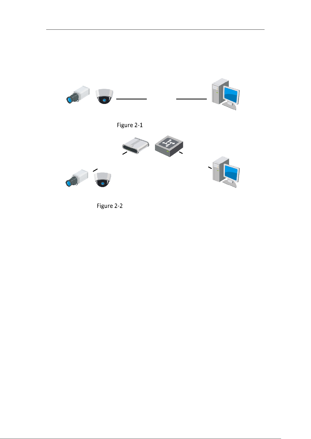
2.1.1 Wiring over the LAN
The following figures show the two ways of cable connection of a network camera
and a computer:
Purpose:
To test the network camera, you can directly connect the network camera to the
Page 13
Network Camera User Manual
12
computer with a network cable as shown in Figure 2-1.
Refer to the Figure 2-2 to set network camera over the LAN via a switch or a
router.
Network Cable
or
Network Camera
Computer
Connecting Directly
Network Cable
Network Cable
or
or
Network Camera Computer
Connecting via a Switch or a Router
2.1.2 Activating the Camera
You are required to activate the camera first by setting a strong password for it
before you can use the camera.
Activation via Web Browser, Activation via SADP, and Activation via Client Software
are all supported.
Activation via Web Browser
Steps:
1. Power on the camera, and connect the camera to the network.
2. Input the IP address into the address bar of the web browser, and click Enter to
enter the activation interface.
Notes:
The default IP address of the camera is 192.168.1.64.
The computer and the camera should belong to the same subnet.
Page 14
Network Camera User Manual
13
For the camera enables the DHCP by default, you need to use the SADP software
to search the IP address.
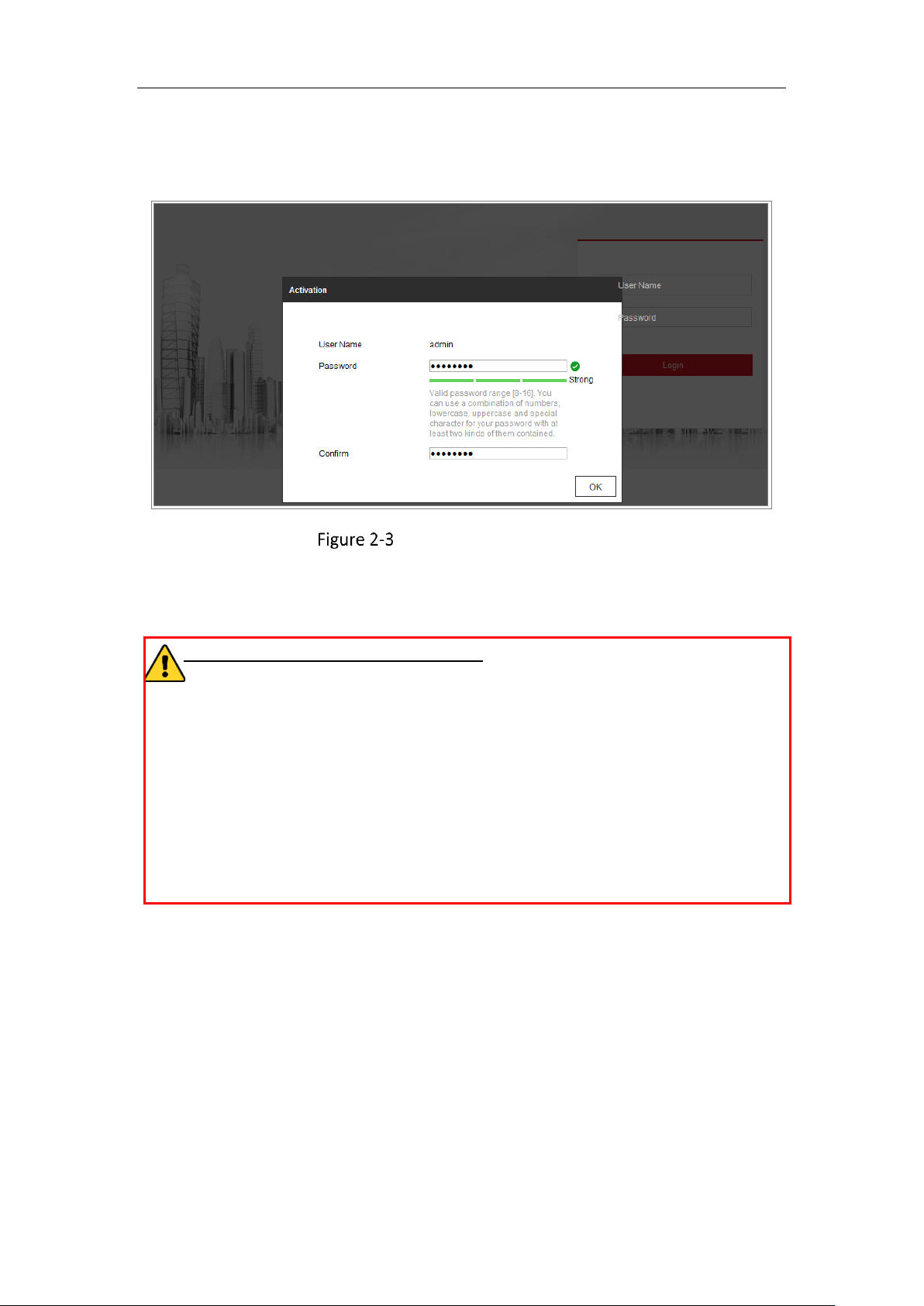
Activation via Web Browser
3. Create and input a password into the password field.
A password with user name in it is not allowed.
STRONG PASSWORD RECOMMENDED–We highly recommend you create a
strong password of your own choosing (using a minimum of 8 characters,
including at least three of the following categories: upper case letters, lower
case letters, numbers, and special characters) in order to increase the security
of your product. And we recommend you reset your password regularly,
especially in the high security system, resetting the password monthly or
weekly can better protect your product.
4. Confirm the password.
5. Click OK to save the password and enter the live view interface.
Activation via SADP Software
SADP software is used for detecting the online device, activating the camera, and
resetting the password.
Get the SADP software from the supplied disk or the official website, and install the
SADP according to the prompts. Follow the steps to activate the camera.
Page 15
Network Camera User Manual
14
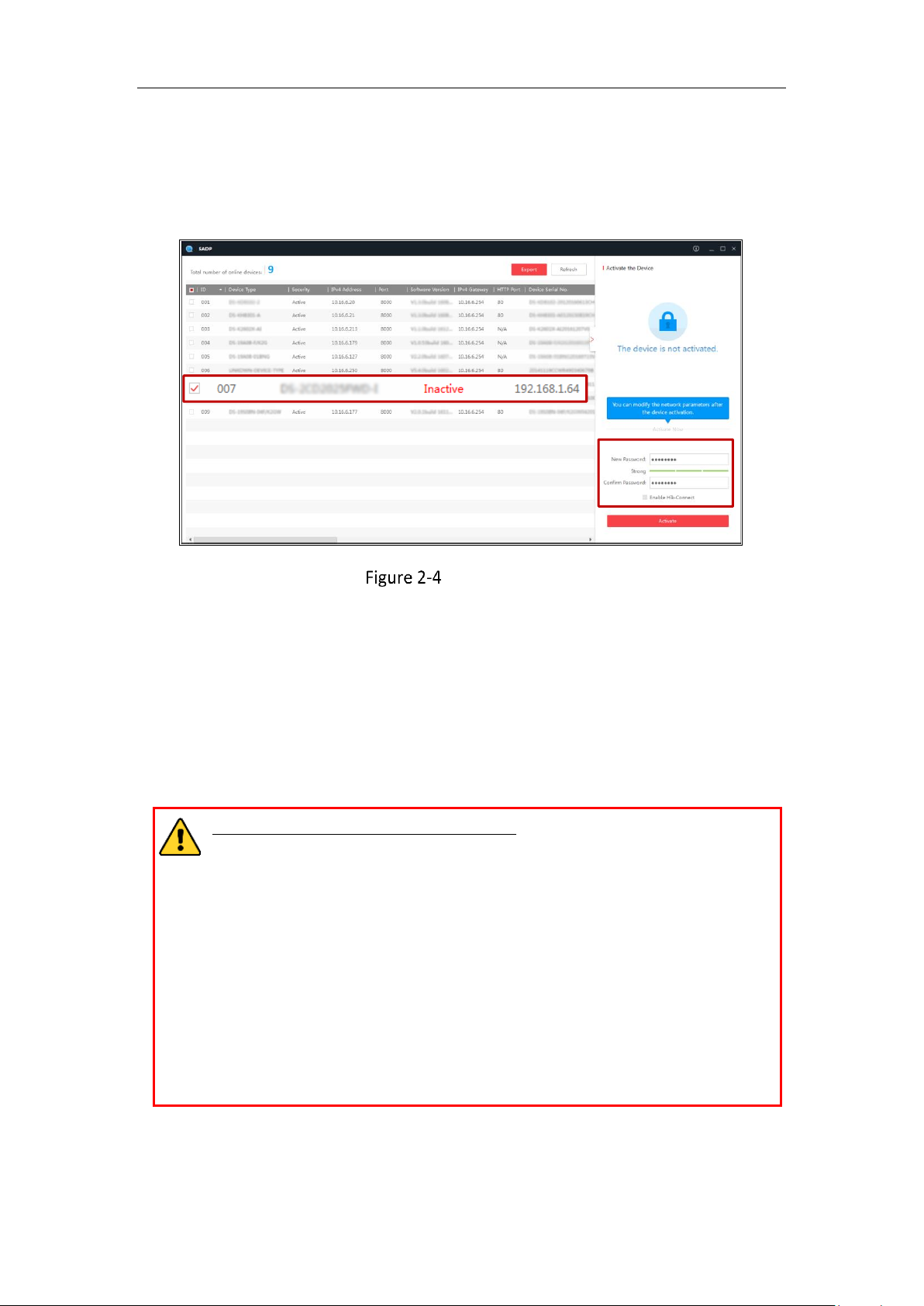
Steps:
1. Run the SADP software to search the online devices.
2. Check the device status from the device list, and select the inactive device.
SADP Interface
Note:
The SADP software supports activating the camera in batch. Refer to the user manual
of SADP software for details.
3. Create and input the password in the password field, and confirm the password.
A password with user name in it is not allowed.
STRONG PASSWORD RECOMMENDED– We highly recommend you
create a strong password of your own choosing (using a minimum of 8
characters, including at least three of the following categories: upper
case letters, lower case letters, numbers, and special characters) in
order to increase the security of your product. And we recommend you
reset your password regularly, especially in the high security system,
resetting the password monthly or weekly can better protect your
product.
Note:
You can enable the Hik-Connect service for the device during activation.
Select inactive device.
Input and confirm
password.
Page 16
Network Camera User Manual
15
4. Click Activate to start activation.
You can check whether the activation is completed on the popup window. If
activation failed, please make sure that the password meets the requirement and try
again.
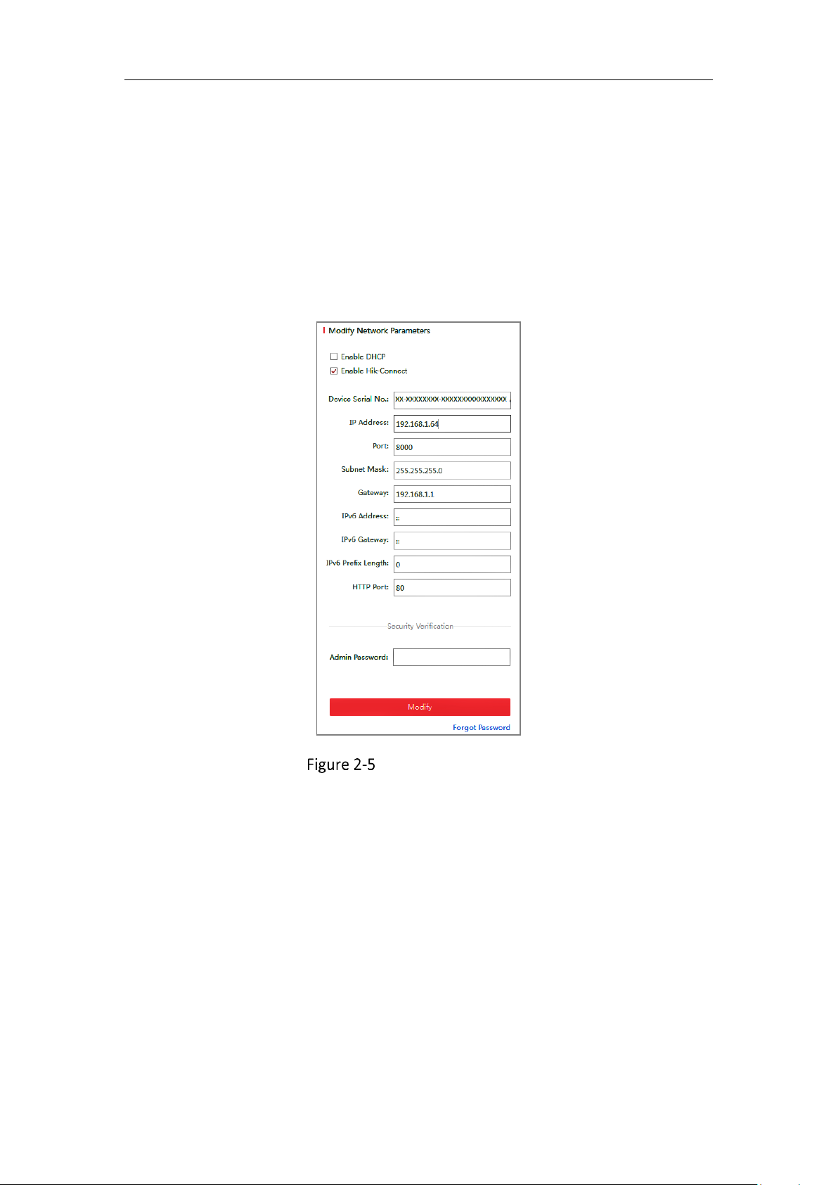
5. Change the device IP address to the same subnet with your computer by either
modifying the IP address manually or checking the checkbox of Enable DHCP.
Modify the IP Address
6. Input the admin password and click Modify to activate your IP address
modification.
The batch IP address modification is supported by the SADP. Refer to the user manual
of SADP for details.
Activation via Client Software
The client software is versatile video management software for multiple kinds of
devices.
Get the client software from the supplied disk or the official website, and install the
Page 17
Network Camera User Manual
16
software according to the prompts. Follow the steps to activate the camera.
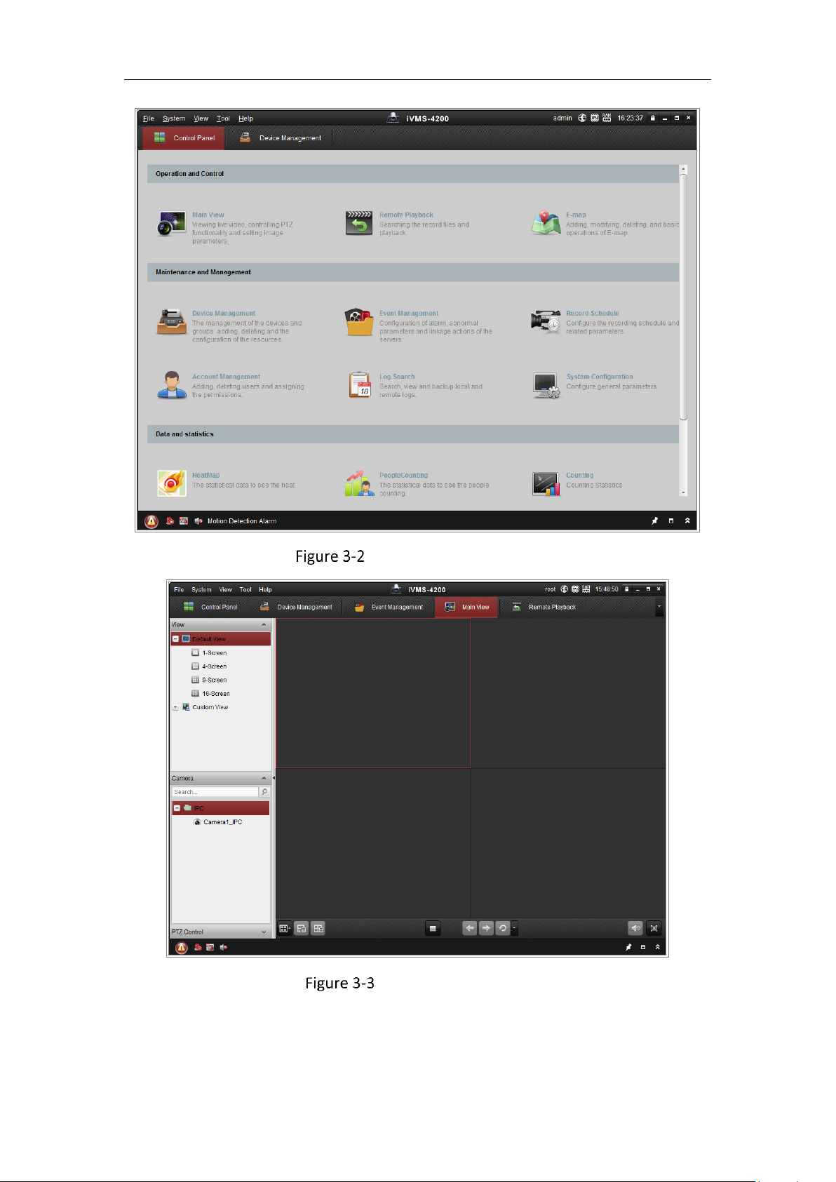
Steps:
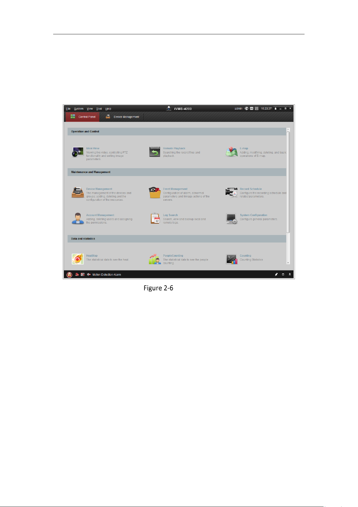
1. Run the client software and the control panel of the software pops up, as shown
in the figure below.
Control Panel
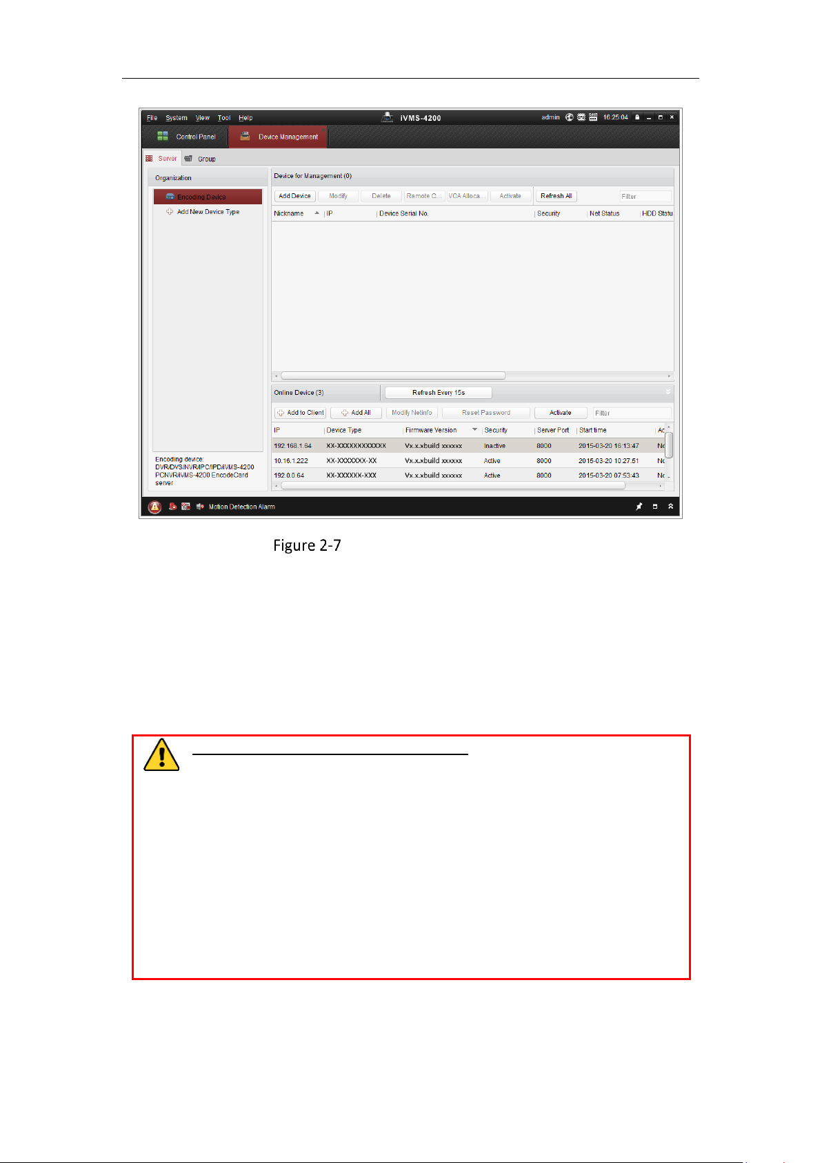
2. Click the Device Management icon to enter the Device Management interface, as
shown in the figure below.
Page 18
Network Camera User Manual
17
Device Management Interface
3. Check the device status from the device list, and select an inactive device.
4. Click the Activate button to pop up the Activation interface.
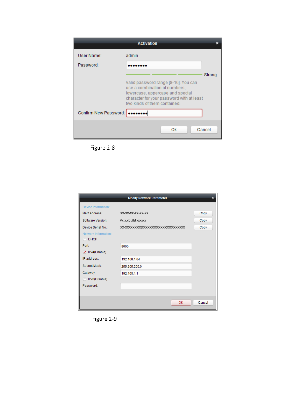
5. Create a password and input the password in the password field, and confirm the
password.
A password with user name in it is not allowed.
STRONG PASSWORD RECOMMENDED–We highly recommend you
create a strong password of your own choosing (using a minimum of 8
characters, including at least three of the following categories: upper
case letters, lower case letters, numbers, and special characters) in order
to increase the security of your product. We recommend you reset your
password regularly, especially in the high security system, resetting the
password monthly or weekly can better protect your product.
Page 19
Network Camera User Manual
18
Activation Interface (Client Software)
6. Click OK button to start activation.
7. Click the Modify Netinfo button to pop up the Network Parameter Modification
interface, as shown in the figure below.
Modifying the Network Parameters
8. Change the device IP address to the same subnet with your computer by either
modifying the IP address manually or checking the checkbox of Enable DHCP.
9. Input the password to activate your IP address modification.
Page 20

Network Camera User Manual
19
2.1.3 (Optional) Setting Security Question
Security question is used to reset the admin password when admin user forgets the
password.
Admin user can follow the pop-up window to complete security question settings
during camera activation. Or, admin user can go to User Management interface to
set up the function.
Setting the Network Camera over the WAN
Purpose:
This section explains how to connect the network camera to the WAN with a static IP
or a dynamic IP.
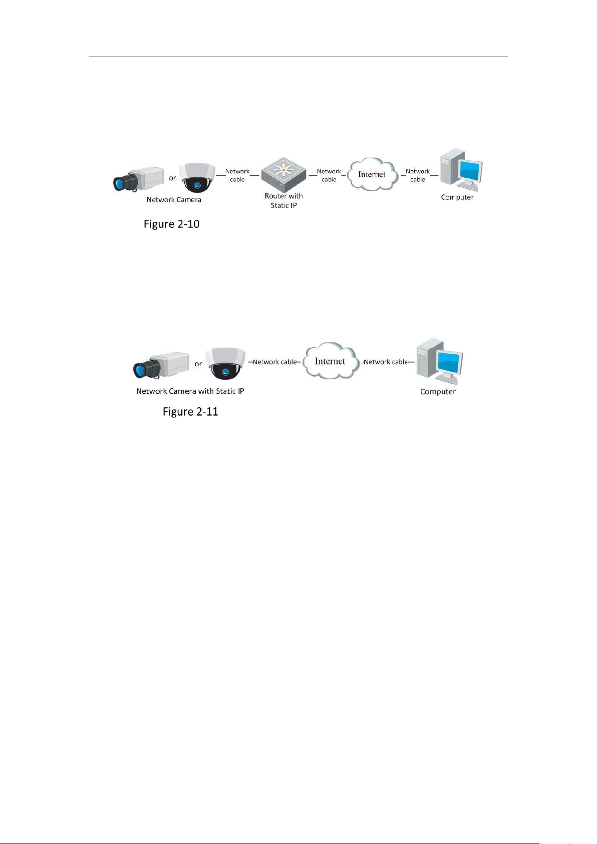
Static IP Connection
Before you start:
Please apply a static IP from an ISP (Internet Service Provider). With the static IP
address, you can connect the network camera via a router or connect it to the WAN
directly.
Connecting the network camera via a router
Steps:
1. Connect the network camera to the router.
2. Assign a LAN IP address, the subnet mask and the gateway. Refer to 2.1.2
Activating the Camera for detailed IP address configuration of the network
camera.
3. Save the static IP in the router.
4. Set port mapping, e.g., 80, 8000, and 554 ports. The steps for port mapping vary
according to the different routers. Please call the router manufacturer for
assistance with port mapping.
Page 21
Network Camera User Manual
20
Note: Refer to Appendix 2 for detailed information about port mapping.
5. Visit the network camera through a web browser or the client software over the
internet.
Accessing the Camera through Router with Static IP
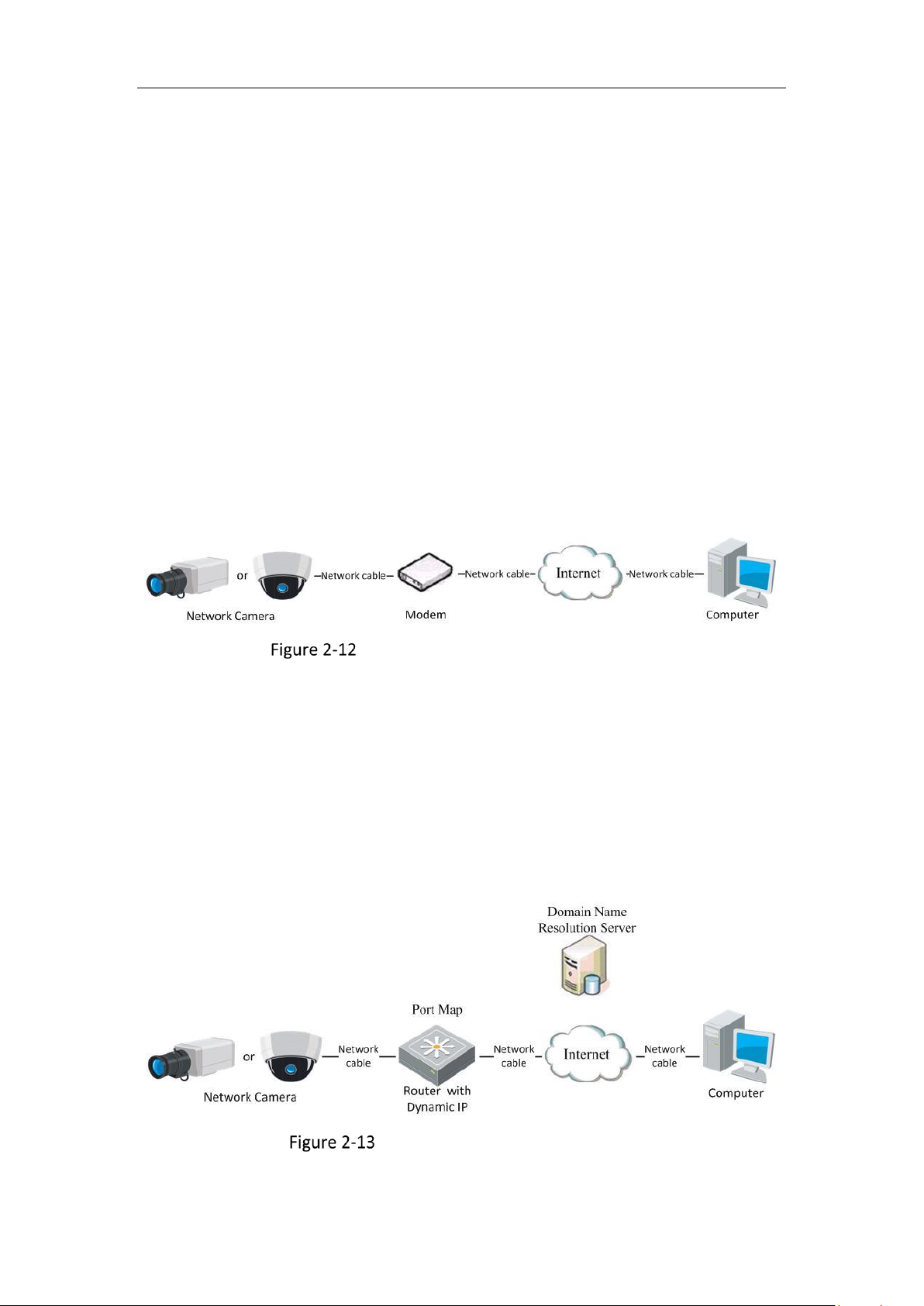
Connecting the network camera with static IP directly
You can also save the static IP in the camera and directly connect it to the internet
without using a router. Refer to 2.1.2 Activating the Camera for detailed IP address
configuration of the network camera.
Accessing the Camera with Static IP Directly
2.2.2 Dynamic IP Connection
Before you start:
Please apply a dynamic IP from an ISP. With the dynamic IP address, you can connect
the network camera to a modem or a router.
Connecting the network camera via a router
Steps:
1. Connect the network camera to the router.
2. In the camera, assign a LAN IP address, the subnet mask and the gateway. Refer
to 2.1.2 Activating the Camera for detailed IP address configuration of the
network camera.
3. In the router, set the PPPoE user name, password and confirm the password.
4. Set port mapping. E.g. 80, 8000, and 554 ports. The steps for port mapping vary
depending on different routers. Please call the router manufacturer for assistance
Page 22
Network Camera User Manual
21
with port mapping.
Note: Refer to Appendix 2 for detailed information about port mapping.
5. Apply a domain name from a domain name provider.
6. Configure the DDNS settings in the setting interface of the router.
7. Visit the camera via the applied domain name.
Connecting the network camera via a modem
Purpose:
This camera supports the PPPoE auto dial-up function. The camera gets a public IP
address by ADSL dial-up after the camera is connected to a modem. You need to
configure the PPPoE parameters of the network camera. Refer to 7.1.3 Configuring
PPPoE Settings for detailed configuration.
Accessing the Camera with Dynamic IP
Note: The obtained IP address is dynamically assigned via PPPoE, so the IP address
always changes after rebooting the camera. To solve the inconvenience of the
dynamic IP, you need to get a domain name from the DDNS provider (E.g.
DynDns.com). Please follow the steps below for normal domain name resolution and
private domain name resolution to solve the problem.
Normal Domain Name Resolution
Normal Domain Name Resolution
Steps:
Page 23

Network Camera User Manual
22
1. Apply a domain name from a domain name provider.
2. Configure the DDNS settings in the DDNS Settings interface of the network
camera. Refer to 7.1.2 Configuring DDNS Settings for detailed configuration.
3. Visit the camera via the applied domain name.
Page 24

Network Camera User Manual
23
Access to the Network
Camera
Accessing by Web Browsers
Note:
For certain camera models, HTTPS is enabled by default and the camera creates an
unsigned certificate automatically. When you access to the camera the first time, the
web browser prompts a notification about the certificate issue.
To cancel the notification, install a signed-certificate to the camera. For detailed
operation, see 0 HTTPS Settings.
Steps:
1. Open the web browser.
2. In the browser address bar, input the IP address of the network camera, and press
the Enter key to enter the login interface.
Note:
The default IP address is 192.168.1.64. You are recommended to change the IP
address to the same subnet with your computer.
3. Input the user name and password and click Login.
The admin user should configure the device accounts and user/operator
permissions properly. Delete the unnecessary accounts and user/operator
permissions.
Note:
The IP address is locked if the admin user performs 7 failed password attempts (5
attempts for the user/operator).
Page 25

Network Camera User Manual
24
Login Interface
4. Click Login.
5. (Optional) Install the plug-in before viewing the live video and operating the
camera. Follow the installation prompts to install the plug-in
Note:
For camera that supports plug-in free live view, if you are using Google Chrome 45
and its above version or Mozilla Firefox 52 and its above version, plug-in
installation is not required. But Picture and Playback functions are hidden. To use
mentioned function via web browser, change to their lower version, or change to
Internet Explorer 8.0 and above version.
Accessing by Client Software
The product CD contains the iVMS-4200 client software. You can view the live video
and manage the camera with the software.
Follow the installation prompts to install the software. The control panel and live
view interface of iVMS-4200 client software are shown as below.
Page 26
Network Camera User Manual
25
iVMS-4200 Control Panel
iVMS-4200 Main View
Page 27
Network Camera User Manual
26
Wi-Fi Settings
Purpose:
By connecting to the wireless network, you do not need to use cable of any kind for
network connection, which is very convenient for the actual surveillance application.
Note: This chapter is only applicable for the cameras with the built-in Wi-Fi module.
Configuring Wi-Fi Connection in Manage and
Ad-hoc Modes
Purpose:
Two connection modes are supported. Choose a mode as desired and perform the
steps to configure the Wi-Fi.
Wireless Connection in Manage Mode
Steps:
1. Enter the Wi-Fi configuration interface.
Configuration> Network> Advanced Settings> Wi-Fi
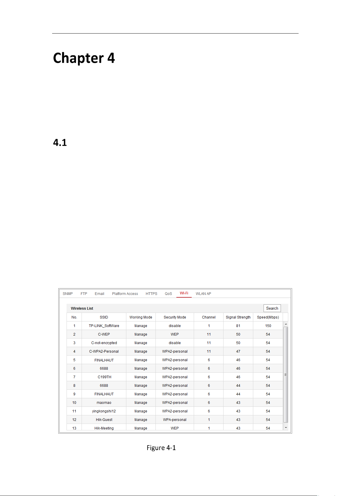
2. Click Search to search the online wireless connections.
Wi-Fi List
Page 28
Network Camera User Manual
27
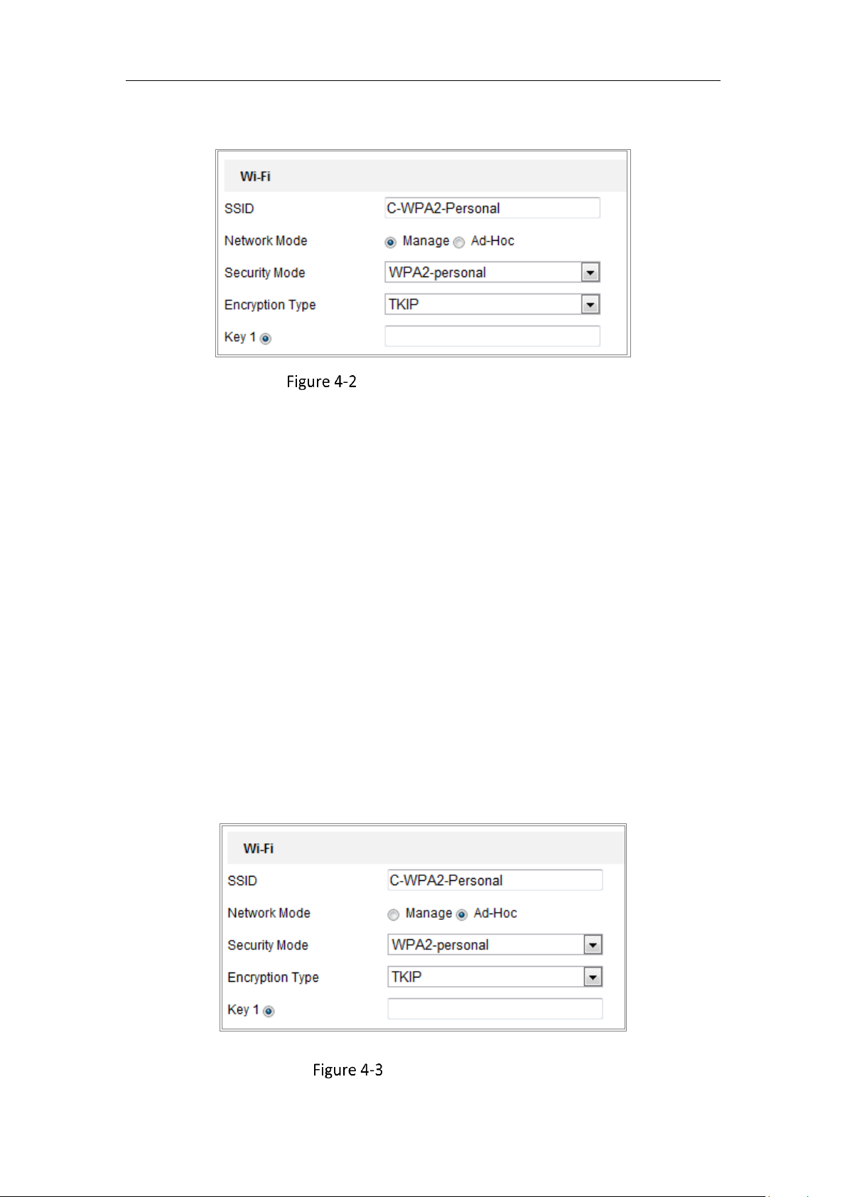
3. Click to choose a wireless connection on the list.
Wi-Fi Setting- Manage Mode
4. Check the radio button to select the Network mode as Manage, and the
Security mode of the network is automatically shown when you select the
wireless network, please do not change it manually.
Note: These parameters are exactly identical with those of the router.
5. Enter the key to connect the wireless network. The key should be that of the
wireless network connection you set on the router.
Wireless Connection in Ad-hoc Mode
If you choose the Ad-hoc mode, you do not need to connect the wireless camera via
a router. The scenario is the same as you connect the camera and the PC directly
with a network cable.
Steps:
1. Choose Ad-hoc mode.
Wi-Fi Setting- Ad-hoc
Page 29
Network Camera User Manual
28
2. Customize a SSID for the camera.
3. Choose the Security Mode of the wireless connection.
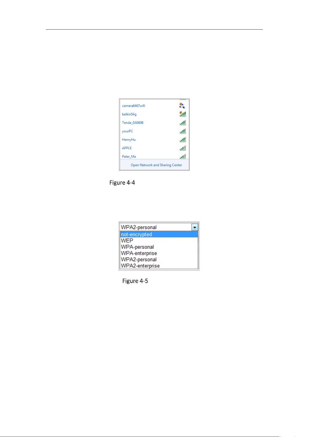
4. Enable the wireless connection function for your PC.
5. On the PC side, search the network and you can see the SSID of the camera
listed.
Ad-hoc Connection Point
6. Choose the SSID and connect.
Security Mode Description:
Security Mode
You can choose the Security Mode as not-encrypted, WEP, WPA-personal,
WPA-enterprise, WPA2-personal, and WPA2-enterprise.
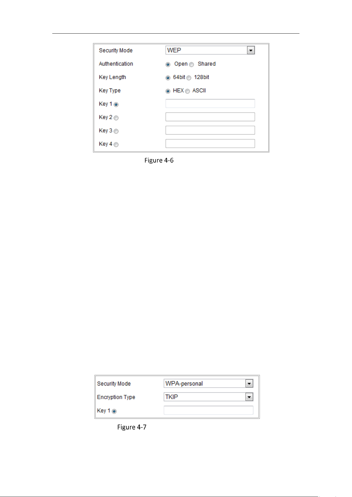
WEP mode:
Page 30
Network Camera User Manual
29
WEP Mode
Authentication - Select Open or Shared Key System Authentication, depending on
the method used by your access point. Not all access points have this option, in
which case they probably use Open System, which is sometimes known as SSID
Authentication.
Key length - This sets the length of the key used for the wireless encryption, 64 or
128 bit. The encryption key length can sometimes be shown as 40/64 and
104/128.
Key type - The key types available depend on the access point being used. The
following options are available:
HEX - Allows you to manually enter the hex key.
ASCII - In this method, the string must be exactly 5 characters for 64-bit WEP and
13 characters for 128-bit WEP.
WPA-personal and WPA2-personal Mode:
Enter the required Pre-shared Key for the access point, which can be a hexadecimal
number or a passphrase.
Security Mode- WPA-personal
WPA- enterprise and WPA2-enterprise Mode:
Page 31

Network Camera User Manual
30
Choose the type of client/server authentication being used by the access point:
EAP-TLS or EAP-PEAP.
EAP-TLS
EAP-TLS
Identity - Enter the user ID to present to the network.
Private key password – Enter the password for your user ID.
EAPOL version - Select the version used (1 or 2) in your access point.
CA Certificates - Upload a CA certificate to present to the access point for
authentication.
EAP-PEAP:
User Name - Enter the user name to present to the network
Password - Enter the password of the network
PEAP Version - Select the PEAP version used at the access point.
Label - Select the label used by the access point.
EAPOL version - Select version (1 or 2) depending on the version used at the
access point.
CA Certificates - Upload a CA certificate to present to the access point for
authentication.
Page 32

Network Camera User Manual
31
For your privacy and to better protect your system against security risks, we
strongly recommend the use of strong passwords for all functions and network
devices. The password should be something of your own choosing (using a
minimum of 8 characters, including at least three of the following categories:
upper case letters, lower case letters, numbers and special characters) in order to
increase the security of your product.
Proper configuration of all passwords and other security settings is the
responsibility of the installer and/or end-user.
Easy Wi-Fi Connection with WPS function
Purpose:
The setting of the wireless network connection is never easy. To avoid the complex
setting of the wireless connection you can enable the WPS function.
WPS (Wi-Fi Protected Setup) refers to the easy configuration of the encrypted
connection between the device and the wireless router. The WPS makes it easy to
add new devices to an existing network without entering long passphrases. There are
two modes of the WPS connection, the PBC mode and the PIN mode.
Note: If you enable the WPS function, you do not need to configure the parameters
such as the encryption type and you do not need to know the key of the wireless
connection.
Steps:
Page 33

Network Camera User Manual
32
Wi-Fi Settings - WPS
PBC Mode:
PBC refers to the Push-Button-Configuration, in which the user simply has to push a
button, either an actual or virtual one (as the button on the
configuration interface of the IE browser), on both the Access Point (and a registrar
of the network) and the new wireless client device.
1. Check the checkbox of to enable WPS.
2. Choose the connection mode as PBC.
Note: Support of this mode is mandatory for both the Access Points and the
connecting devices.
3. Check on the Wi-Fi router to see if there is a WPS button. If yes, push the button
and you can see the indicator near the button start flashing, which means the WPS
function of the router is enabled. For detailed operation, please see the user guide of
the router.
4. Push the WPS button to enable the function on the camera.
If there is not a WPS button on the camera, you can also click the virtual button to
enable the PBC function on the web interface.
5. Click Connect button.
When the PBC mode is both enabled in the router and the camera, the camera and
Page 34

Network Camera User Manual
33
the wireless network is connected automatically.
PIN Mode:
The PIN mode requires a Personal Identification Number (PIN) to be read from either
a sticker or the display on the new wireless device. This PIN must then be entered to
connect the network, usually the Access Point of the network.
Steps:
1. Choose a wireless connection on the list and the SSID is loaded automatically.
2. Choose Use route PIN code.
Use PIN Code
If the PIN code is generated from the router side, you should enter the PIN code you
get from the router side in the Router PIN code field.
3. Click Connect.
Or
You can generate the PIN code on the camera side. And the expired time for the PIN
code is 120 seconds.
1. Click Generate.
2. Enter the code to the router, in the example, enter 48167581 to the router.
Page 35

Network Camera User Manual
34
IP Property Settings for Wireless Network
Connection
The default IP address of wireless network interface controller is 192.168.1.64. When
you connect to the wireless network, you can change the default IP.
Steps:
1. Enter the TCP/IP configuration interface.
Configuration> Network> Basic Settings > TCP/IP
2. Select the Wlan tab.
Setting WLAN Parameters
3. Customize the IPv4 address, the IPv4 Subnet Mask and the Default Gateway.
The setting procedure is the same with that of LAN.
If you want to be assigned the IP address, you can check the checkbox to enable
the DHCP.
Page 36

Network Camera User Manual
35
Live View
Live View Page
Purpose:
The live view page allows you to view the real-time video, capture images, record
videos, realize PTZ control, configure display settings, OSD settings, video/audio
settings, VCA settings and set/call presets.
Log in the network camera to enter the live view page, or you can click Live View on
the menu bar of the main page to enter the live view page.
Descriptions of the live view page:
Toolbar
Live View
Window
Menu Bar
Quick Sutup
PTZ Control
Settings
Live View Page
Menu Bar
Click each tab to enter Live View, Playback, Picture, Application, Configuration and
Smart Display page respectively.
Live View Window
Display the live video.
Toolbar
Toolbar allows you to adjust the live view window size, the stream type, and the
plug-ins. It also allows you to process the operations on the live view page, e.g.,
start/stop live view, capture, record, audio on/off, two-way audio, start/stop digital
zoom, etc.
Page 37

Network Camera User Manual
36
For IE (Internet Explorer) users, plug-ins as webcomponents and quick time are
selectable. And for Non-IE users, webcomponents, quick time, VLC or MJPEG are
selectable if the web browser supports them.
Note:
For camera that supports plug-in free live view, when Google Chrome 45 and its
above version or Mozilla Firefox 52 and its above version are used, plug-in
installation is not required. But Picture and Playback functions are hidden. To use
mentioned function via web browser, change to their lower versions, or change to
Internet Explorer 8.0 and its above version.
Quick Setup
It allows quick setup of PTZ control, image, video/audio settings and VCA settings on
live view page.
PTZ Control Settings
Perform panning, tilting and zooming actions of the camera. Control the light and
the wiper (only available for cameras supporting PTZ function). Set/call/delete the
presets or patrols for PTZ cameras.
Live Operation
In the live view window as shown in Figure 5-1, click on the toolbar to start the
live view of the camera.
Live View Toolbar
Toolbar Description
Icon
Description
/
Start/Stop live view.
4:3 window size.
16:9 window size.
Original widow size.
Self-adaptive window size.
Original ratio window size.
, , ,
Live view with the different video streams.
Page 38

Network Camera User Manual
37
Icon
Description
etc.
Supported video streams vary according to camera models.
For the camera models that support 10 streams, go to Video/Audio >
Custom to add the streams.
Click to select the third-party plug-in.
Manually capture the picture.
/
Manually start/stop recording.
/
Audio on and adjust volume /Mute.
/
Turn on/off microphone.
/
Start/stop digital zoom function.
/
Start/stop pixel counter
Click the button to display pictures captured by camera.
Note: The function is only available for certain camera models that
support face capture.
Note: The icons vary according to the different camera models.
Pixel Counter:
Steps:
1. Click Start Pixel Counter to enable the function.
2. Drag the mouse on the image to select the desired rectangle area. The width
pixel and height pixel is displayed on the bottom of the web.
3. Click the button again to stop the function.
Note:
The pixel counter is only supported under the main stream and only one rectangle is
supported.
Full-screen Mode:
You can double-click on the live video to switch the current live view into
full-screen or return to normal mode from the full-screen.
Recording and Capturing Pictures Manually
In the live view interface, click on the toolbar to capture the live pictures or click
to record the live view. The saving paths of the captured pictures and clips can
Page 39

Network Camera User Manual
38
be set on the Configuration > Local page. To configure remote scheduled recording,
please refer to 6.1 Configuring Local Parameters.
Note: The captured image will be saved as JPEG file or BMP file in your computer.
Quick Setup
Steps:
1. Click on the right of the live view window to show the quick setup panel. Click
to hide it.
2. Specify PTZ, Display, OSD and Video/Audio and VCA resource parameters.
5.4.1 Operating PTZ Control
PTZ Control Panel
Purpose:
You can use the PTZ control buttons to realize pan/tilt/zoom control of the camera.
Note: To realize PTZ control, the camera connected to the network must support the
PTZ function or have a pan/tilt unit installed to the camera. Please properly set the
PTZ parameters on RS-485 settings page by referring to 6.2.4 Configuring RS-485
Settings.
Click the direction buttons to control the pan/tilt movements.
PTZ Control Panel
Page 40

Network Camera User Manual
39
Click the zoom/focus/iris buttons to realize lens control.
Notes:
There are eight direction arrows ( , , , , , , , ) in the control
panel. Click the arrows to realize adjustment in the relative positions.
For the cameras that support lens movements only, the direction buttons are
invalid.
Descriptions of PTZ Control Panel
Icon
Description
Zoom in/out
Focus near/far
Iris +/-
PTZ speed adjustment
Light on/off
Wiper on/off
Auxiliary focus
Initialize lens
Adjust speed of pan/tilt movements
Start Manual Tracking
Start 3D Zoom
Setting/Calling a Preset
Setting a Preset:
1. In the PTZ control panel, select a preset number from the preset list.
Setting a Preset
Page 41

Network Camera User Manual
40
2. Use the PTZ control buttons to move the lens to the desired position.
• Pan the camera to the right or left.
• Tilt the camera up or down.
• Zoom in or out.
• Refocus the lens.
3. Click to finish the setting of the current preset.
4. You can click to delete the preset.
Calling a Preset:
This feature enables the camera to point to a specified preset scene manually or
automatically when an event takes place.
For the defined preset, you can call it at any time to the desired preset scene.
In the PTZ control panel, select a defined preset from the list and click to call the
preset.
Or you can place the mouse on the presets interface, and call the preset by typing
the preset No. to call the corresponding presets.
Calling a Preset
Setting/Calling a Patrol
Note:
No less than 2 presets should be configured before you set a patrol.
Steps:
1. Click to enter the patrol configuration interface.
2. Select a path No., and click to add the configured presets.
Page 42

Network Camera User Manual
41
3. Select the preset, and input the patrol duration and patrol speed.
4. Click OK to save the first preset.
5. Follow the steps above to add the other presets.
Add Patrol Path
6. Click OK to save a patrol.
7. Click to start the patrol, and click to stop it.
8. (Optional) Click to delete a patrol.
5.4.2 General Settings
Display Settings
Scene: Select a scene according to actual installation environment. (Only certain
camera models support.)
WDR: The WDR (Wide Dynamic Range) function helps the camera provide clear
images even under back light circumstances. When there are both very bright
and very dark areas simultaneously in the field of view, WDR balances the
brightness level of the whole image and provide clear images with details. You
can enable or disable the WDR function and set the level.
HLC: High Light Compensation makes the camera identify and suppress the
strong light sources that usually flare across a scene. This makes it possible to
see the detail of the image that would normally be hidden.
OSD (On Screen Display)
Set text information displayed on screen. Alignment adjustment is available for Text
Overlay. Save the settings after configuration.
Page 43

Network Camera User Manual
42
Video/Audio
Resolution and Max. Bit rate are adjustable. Click to change stream.
5.4.3 VCA Resource
VCA Resource offers options to enable certain VCA functions and hide others. It helps
allocate more resources to the wanted functions. A reboot is required after setting
the VCA Resource.
Note:
VCA Resource function varies according to different camera models.
VCA options are mutually exclusive.
Only certain camera models support the function.
Install Plug-in
Certain operation system and web browser may restrict the display and operation of
the camera function. You should install plug-in or complete certain settings to ensure
normal display and operation.
Operation
System
Web Browser
Operation
Windows
Internet Explorer 8+
Google Chrome 57 and earlier
version
Mozilla Firefox 52 and earlier
version
Follow pop-up prompts to
complete plug-in installation.
Google Chrome 57+
Mozilla Firefox 52+
Click to download
and install plug-in.
Mac OS
Google Chrome 57+
Mozilla Firefox 52+
Mac Safari 16+
Plug-in installation is not
required.
Enable WebSocket or
WebSockets (Configuration >
Network > Advanced
Settings > Network Service)
for normal live view.
Display and operation of certain
functions are restricted. For
Page 44

Network Camera User Manual
43
example, Playback and Picture are
not available. For detailed
restricted function, refer to the
actual device.
Note:
The camera only supports Windows and Mac OS system and do not support Linux
system.
Page 45

Network Camera User Manual
44
Network Camera
Configuration
Configuring Local Parameters
Purpose:
The local configuration refers to the parameters of the live view, record files and
captured pictures. The record files and captured pictures are the ones you record and
capture using the web browser and thus the saving paths of them are on the PC
running the browser.
Steps:
1. Enter the Local Configuration interface: Configuration > Local.
2. Configure the following settings:
Live View Parameters: Set the protocol type and live view performance.
Protocol Type: TCP, UDP, MULTICAST and HTTP are selectable.
TCP: Ensures complete delivery of streaming data and better video quality,
yet the real-time transmission will be affected.
UDP: Provides real-time audio and video streams.
HTTP: Allows the same quality as of TCP without setting specific ports for
streaming under some network environments.
MULTICAST: It’s recommended to select MCAST type when using the
Multicast function. For detailed information about Multicast, refer to 7.1.1
Configuring TCP/IP Settings.
Play Performance: Set the live view performance to Shortest Delay, Balanced,
Fluent or Custom. For Custom, you can set the frame rate for live view.
Rules: It refers to the rules on your local browser, select enable or disable to
display or not display the colored marks when the motion detection, face
detection, or intrusion detection is triggered. E.g., enabled as the rules are,
Page 46

Network Camera User Manual
45
and the face detection is enabled as well, when a face is detected, it will be
marked with a green rectangle on the live view.
Display POS Information: Enable the function, feature information of the
detected target is dynamically displayed near the target in the live image.
The feature information of different functions is different. For example, ID and
waiting time for Queue Management, height for People Counting, etc.
Note:
Display POS Information is only available for certain camera models.
Image Format: Choose the image format for picture capture.
Live View Parameters
Record File Settings: Set the saving path of the recorded video files. Valid for the
record files you recorded with the web browser.
Record File Size: Select the packed size of the manually recorded and
downloaded video files to 256M, 512M or 1G. After the selection, the
maximum record file size is the value you selected.
Save record files to: Set the saving path for the manually recorded video files.
Save downloaded files to: Set the saving path for the downloaded video files
in playback mode.
Picture and Clip Settings: Set the saving paths of the captured pictures and
clipped video files. Valid for the pictures you capture with the web browser.
Save snapshots in live view to: Set the saving path of the manually captured
pictures in live view mode.
Save snapshots when playback to: Set the saving path of the captured
pictures in playback mode.
Save clips to: Set the saving path of the clipped video files in playback mode.
Page 47

Network Camera User Manual
46
Note: You can click Browse to change the directory for saving the clips and pictures,
and click Open to open the set folder of clips and picture saving.
3. Click Save to save the settings.
Configure System Settings
Purpose:
Follow the instructions below to configure the system settings, include System
Settings, Maintenance, Security, and User Management, etc.
6.2.1 Configuring Basic Information
Enter the Device Information interface: Configuration > System > System Settings >
Basic Information.
In the Basic Information interface, you can edit the Device Name and Device No.
Other information of the network camera, such as Model, Serial No., Firmware
Version, Encoding Version, Number of Channels, Number of HDDs, Number of Alarm
Input and Number of Alarm Output are displayed. The information cannot be
changed in this menu. It is the reference for maintenance or modification in future.
6.2.2 Configuring Time Settings
Purpose:
You can follow the instructions in this section to configure the time synchronization
and DST settings.
Steps:
1. Enter the Time Settings interface, Configuration > System> System Settings >
Time Settings.
Page 48

Network Camera User Manual
47
Time Settings
2. Select the Time Zone of your location from the drop-down menu.
3. Configure the NTP settings.
(1) Click to enable the NTP function.
(2) Configure the following settings:
Server Address: IP address of NTP server.
NTP Port: Port of NTP server.
Interval: The time interval between the two synchronizing actions with NTP
server.
(3) (Optional) You can click the Test button to test the time synchronization
function via NTP server.
Time Sync by NTP Server
Page 49

Network Camera User Manual
48
Note: If the camera is connected to a public network, you should use a NTP server
that has a time synchronization function, such as the server at the National Time
Center (IP Address: 210.72.145.44). If the camera is set in a customized network, NTP
software can be used to establish a NTP server for time synchronization.
Configure the manual time synchronization.
(1) Check the Manual Time Sync. to enable the manual time synchronization
function.
(2) Click the icon to select the date, time from the pop-up calendar.
(3) (Optional) You can check Sync. with computer time item to synchronize the
time of the device with that of the local PC.
Time Sync Manually
Click Save to save the settings.
6.2.3 Configuring RS-232 Settings
The RS-232 port can be used in two ways:
Console: Connect a computer to the camera through the serial port. Device
parameters can be configured by using software such as HyperTerminal. The
serial port parameters must be the same as the serial port parameters of the
camera.
Transparent Channel: Connect a serial device directly to the camera. The serial
device will be controlled remotely by the computer through the network.
Page 50

Network Camera User Manual
49
Steps:
1. Enter RS-232 Port Setting interface: Configuration > System > System Settings >
RS-232.
2. Configure the Baud Rate, Data Bit, Stop Bit, Parity, Flow Control, and Usage.
RS-232 Settings
Note: If you want to connect the camera by the RS-232 port, the parameters of the
RS-232 should be the same with the parameters you configured here.
3. Click Save to save the settings.
6.2.4 Configuring RS-485 Settings
Purpose:
The RS-485 serial port is used to control the PTZ of the camera. The configuring of
the PTZ parameters should be done before you control the PTZ unit.
Steps:
1. Enter RS-485 Port Setting interface: Configuration > System > System Settings >
RS-485.
Page 51

Network Camera User Manual
50
RS-485 Settings
2. Set the RS-485 parameters and click Save to save the settings.
By default, the Baud Rate is set as 9600 bps, the Data Bit is 8, the stop bit is 1 and
the Parity and Flow Control is None.
Note: The Baud Rate, PTZ Protocol and PTZ Address parameters should be exactly the
same as the PTZ camera parameters.
6.2.5 Configuring DST Settings
Purpose:
Daylight Saving Time (DST) is a way of making better use of the natural daylight by
setting your clock forward one hour during the summer months, and back again in
the fall.
Configure the DST according to your actual demand.
Steps:
1. Enter the DST configuration interface.
Configuration > System > System Settings > DST
Page 52

Network Camera User Manual
51
DST Settings
2. Select the start time and the end time.
3. Select the DST Bias.
4. Click Save to activate the settings.
6.2.6 Configuring External Devices
Purpose:
For the device supported external devices, including the wiper on the housing or the
LED light, you can control them via the Web browser. External devices vary according
to the different camera models.
Steps:
1. Enter the External Device configuration interface.
Configuration > System > System Settings > External Device
External Device Settings
2. Check the Enable Supplement Light checkbox to enable the LED Light.
3. Move the slider to adjust the low beam brightness and high beam brightness.
4. Select the mode for LED light. Timing and Auto are selectable.
Timing: The LED will be turned on by the schedule you set. You should set
the Start Time and End Time.
Set Schedule
Page 53

Network Camera User Manual
52
Auto: The LED will be turned on according to the environment illumination.
5. Click Save to save the settings.
6.2.7 Configuring VCA Resource
Purpose:
VCA resource offers you options to enable certain VCA functions according to actual
need when several VCA functions are available. It helps allocate more resources to
the desired functions.
Steps:
1. Enter VCA Resource configuration interface:
Configuration > System > System Settings > VCA Resource
2. Select a desired VCA combination. Available VCA combination varies according to
different camera models.
3. Click Save to save the settings. A reboot is required after setting the VCA
Resource.
Notes:
• VCA combinations are mutually exclusive. When you activate one combination,
the others are hidden.
• Only certain camera models support the function.
6.2.8 Configuring Metadata Settings
Purpose:
Metadata is the raw data the camera collects before algorithm processing. Metadata
of intrusion detection, line crossing detection, region entrance detection, region
exiting detection, unattended baggage detection, object removal, queue
management and face capture can be uploaded. If enabled, the metadata of the
corresponding event are available for users to explore the possibility of various data
usage.
Steps:
1. Enter Metadata settings interface:
Page 54

Network Camera User Manual
53
Configuration > System > System Settings > metadata Settings
2. Check the checkbox of the corresponding function to enable the metadata
function.
The metadata of the smart event includes the target ID, target coordinate and
time information.
The metadata of queue management includes the rule information, region ID,
target ID, target coordinate and time information. The camera detects the whole
image by default. If you have set the region in the queue management settings,
the camera detects the configured region.
The metadata of face capture includes the rule information, target ID, target
coordinate, face grading and time information. The camera detects the whole
image by default. If the region is configured in the face capture settings, the
camera detects the configured region.
3. Check Enable Stream Rule to overlay the stream rule on the live view image.
Make sure you have checked Sub-stream and selected the Sub-stream in the live
view.
4. Check Overlay Rule Frame and Target Frame on Background Picture to enable
the function. Make sure you have checked Sub-stream and selected the
Sub-stream in the live view.
Note: Only certain camera models support the function.
6.2.9 Open Source Software License
Information about the open source software that applies to the IP camera can be
checked if required. Go to Configuration > System Settings > About.
Maintenance
Upgrade & Maintenance
Purpose:
Page 55

Network Camera User Manual
54
The upgrade & maintenance interface allows you to process the operations, including
reboot, partly restore, restore to default, export/import the configuration files, and
upgrade the device.
Enter the Maintenance interface: Configuration > System > Maintenance > Upgrade
& Maintenance.
Reboot: Restart the device.
Restore: Reset all the parameters except the IP parameters and user information
to the default settings.
Default: Restore all the parameters to the factory default.
Notes:
• After restoring the default settings, the IP address is also restored to the
default IP address, please be careful for this action.
• For camera that supports Wi-Fi, wireless dial, or wlan function, Restore
action does not restore the related settings of mentioned functions to
default.
Information Export
Device Parameters: click to export the current configuration file of the camera.
This operation requires admin password to proceed.
For the exported file, you also have to create an encryption password. The
encryption password is required when you import the file to other cameras.
Diagnose Information: click to download log and system information.
Import Config. File
Configuration file is used for the batch configuration of the cameras.
Steps:
1. Click Browse to select the saved configuration file.
2. Click Import and input the encryption password that you set during
exporting.
Note: You need to reboot the camera after importing configuration file.
Upgrade: Upgrade the device to a certain version.
Steps:
Page 56

Network Camera User Manual
55
1. Select firmware or firmware directory to locate the upgrade file.
Firmware: Locate the exact path of the upgrade file.
Firmware Directory: Only the directory the upgrade file belongs to is
required.
2. Click Browse to select the local upgrade file and then click Upgrade to start
remote upgrade.
Note: The upgrading process will take 1 to 10 minutes. Please do not disconnect
power of the camera during the process, and the camera reboots automatically
after upgrade.
6.3.2 Log
Purpose:
The operation, alarm, exception and information of the camera can be stored in log
files. You can also export the log files on your demand.
Before you start:
Please configure network storage for the camera or insert a SD card in the camera.
Steps:
1. Enter log searching interface: Configuration > System > Maintenance > Log.
Log Searching Interface
2. Set the log search conditions to specify the search, including the Major Type,
Minor Type, Start Time and End Time.
3. Click Search to search log files. The matched log files will be displayed on the log
list interface.
Page 57

Network Camera User Manual
56
Log Searching
4. To export the log files, click Export to save the log files.
6.3.3 System Service
Purpose:
System service settings refer to the hardware service the camera supports.
Supported functions vary according to the different cameras. For the cameras
support IR Light, ABF (Auto Back Focus), Auto Defog, or Status LED, you can select to
enable or disable the corresponding service according to the actual demands.
ABF: When ABF function is enabled, you can click on PTZ control panel to realize
auxiliary focus.
Third Stream: For some models, third stream is not enabled by default. Check Enable
Third Stream to enable the function.
eMMC Protection: If you enable eMMC protection, the lifespan of the eMMC is
displayed.
Enable Motion Detection: Check Enable Motion Detection to enable the function.
Page 58

Network Camera User Manual
57
6.3.4 Security Audit Log
Purpose:
The security audit logs refer to the security operation logs. You can search and
analyze the security log files of the camera so that to find out the illegal intrusion and
troubleshooting the security events. Security audit logs can be saved on device flash.
The log will be saved every half hour after device booting.
Due to limited saving space of the flash, you can also save the logs on a log server.
Configure the server settings at Advanced Settings.
Searching Logs
Steps:
1. Enter log searching interface: Configuration > System > Maintenance > Security
Audit Log.
Security Audit Log Searching Interface
2. Set the log search conditions to specify the search, including the Major Type,
Minor Type, Start Time and End Time.
3. Click Search to search log files. The matched log files will be displayed on the log
list interface.
Page 59

Network Camera User Manual
58
Log Searching
4. To export the log files, click Export to save the log files.
Setting Log Server
Steps:
1. Check Enable Log Upload Server.
2. Check Enable Encrypted Transmission. Make sure you have installed the
certificate in Certificate Management.
3. Input Log Server IP and Log Server Port.
4. Click Test to test settings.
5. Install certificates. Client certificate and CA certificate are required.
• Client Certificate
(1) Click Create button to create the certificate request. Fill in the required
information in the popup window.
(2) Click Download to download the certificate request and submit it to the
trusted certificate authority for signature.
(3) Install the signed certificate to the device.
• CA Certificate
Install the CA certificate to the device.
Note: Only certain camera models support the function.
Page 60

Network Camera User Manual
59
Security Settings
Configure the parameters, including Authentication, IP Address Filter, and Security
Service from security interface.
Authentication
Purpose:
You can specifically secure the stream data of live view.
Steps:
1. Enter the Authentication interface: Configuration > System > Security >
Authentication.
Authentication
2. Set up authentication method for RTSP authentication and WEB authentication.
Caution:
Digest is the recommended authentication method for better data security. You
must be aware of the risk if you adopt basic as the authentication method.
3. Click Save to save the settings.
6.4.2 IP Address Filter
Purpose:
This function makes it possible for access control.
Steps:
1. Enter the IP Address Filter interface: Configuration > System > Security > IP
Address Filter
Page 61

Network Camera User Manual
60
IP Address Filter Interface
2. Check Enable IP Address Filter.
3. Select the IP Address Filter Type in the drop-down list, Forbidden and Allowed
are selectable.
4. Set the IP Address Filter list.
Add an IP Address
Steps:
(1) Click the Add to add an IP.
(2) Check IP or IP Segment.
(3) Input the IP Address or IP Segment.
Add an IP
(4) Click the OK to finish adding.
Modify an IP Address
Steps:
(1) Left-click an IP address from filter list and click Modify.
(2) Modify the IP address in the text filed.
Page 62

Network Camera User Manual
61
Modify an IP
(3) Click the OK to finish modifying.
Delete an IP Address or IP Addresses.
Select the IP address(es) and click Delete.
5. Click Save to save the settings.
6.4.3 Security Service
Purpose:
To enable the remote login, and improve the data communication security, the
camera provides the security service for better user experience.
Note: Only certain camera models support the function.
Steps:
1. Enter the security service configuration interface: Configuration > System >
Security > Security Service.
Security Service
2. Check the checkbox of Enable Illegal Login Lock.
Illegal Login Lock: it is used to limit the user login attempts. Login attempt from
the IP address is rejected if admin user performs 7 failed user name/password
attempts (5 times for the operator/user).
Note: If the IP address is rejected, you can try to login the device after 30
minutes.
Page 63

Network Camera User Manual
62
6.4.4 Advanced Security
Purpose:
Advanced security offers options to manage more network security settings of the
device.
Security Reinforce
Check the checkbox to enable the function. Security reinforce is a solution to
enhance network security. With the function enabled, risky functions, protocols,
ports of the device are disabled and more secured alternative functions,
protocols and ports are enabled.
Control Timeout Settings
If you enable the function and set timeout period, you will be logged out when
you make no operation to the device via web browser (Viewing live image and
playback are not included.) for the set timeout period.
Algorithm
Displays the currently active digest algorithm. If Security Reinforce is enabled,
MD5 is disabled and SHA256 is enabled instead.
Note: Only certain camera models support the function.
6.4.5 Certificate Management
Purpose:
It helps to manage the server/client certificates and CA certificate, and sends an
alarm if the certificates will expire, or are expired/abnormal.
Server/Client Certificate
Create Self-signed Certificate
Steps:
1. Enter the security service configuration interface: Configuration > System >
Security > Certificate Management.
Page 64

Network Camera User Manual
63
Certificate Management
2. Click Create Self-signed Certificate.
3. Enter the Certificate ID, Country, Hostname/IP, Validity and other
information. The certificate ID should be digits or letters and be no more
than 64 characters.
4. Click OK.
5. (Optional) You can click Export to export the certificate, or click Delete to
delete the certificate to recreate a certificate, or click Certificate Properties
to view the certificate details.
Create Certificate Request
Steps:
1. Select a self-signed certificate.
2. Click Create Certificate Request.
3. Enter the related information.
4. Click OK.
Import Certificate
Steps:
1. Click Import.
Page 65

Network Camera User Manual
64
2. Click Create Certificate Request.
3. Enter the Certificate ID, click Browser to select the desired server/client
certificate, select the desired import method and enter the required
information.
4. Click OK.
5. (Optional) You can click Export to export the certificate, or click Delete to
delete the certificate to recreate a certificate, or click Certificate Properties
to view the certificate details.
Notes:
● Up to 16 certificates are allowed.
● If certain functions are using the certificate, it cannot be deleted.
● You can view the functions that are using the certificate in the Functions
column.
● You cannot create a certificate that has the same ID with that of the existing
certificate and import a certificate that has the same content with that of
the existing certificate.
CA Certificate
Steps:
1. Click Import.
2. Enter the Certificate ID, click Browser to select the desired server/client
certificate, select the import method and enter the required information.
3. Click OK.
Note: Up to 16 certificates are allowed.
Enable Certificate Expiration Alarm
Steps:
1. Check Enable Certificate Expiration Alarm. If enabled, you will receive an
email or the camera links to the surveillance center that the certificate will
expire soon, or is expired or abnormal.
2. Set the Remind Me Before Expiration (day), Alarm Frequency (day) and
Detection Time (hour).
Page 66

Network Camera User Manual
65
Notes:
● If you set the reminding day before expiration to 1, then the camera will
remind you the day before the expiration day. 1 to 30 days are available.
Seven days is the default reminding days.
● If you set the reminding day before expiration to 1, and the detection
time to 10:00, and the certificate will expire in 9:00 the next day, the
camera will remind you in 10:00 the first day.
3. Click Save to save the settings.
User Management
User Management
As Administrator
The admin user can add, delete or modify user accounts, and grant them
different permissions. We highly recommend you manage the user accounts and
permissions properly.
Enter the User Management interface: Configuration > System > User
Management
Note:
Admin password if required for adding and modifying a user account.
User Management Interface
Adding a User
The admin user has all permissions by default and can create/modify/delete
other accounts.
The admin user cannot be deleted and you can only change the admin password.
Page 67

Network Camera User Manual
66
Steps:
1. Click Add to add a user.
2. Input the Admin Password, User Name, select Level and input Password.
Notes:
● Up to 31 user accounts can be created.
● Users of different levels own different default permissions. Operator and
user are selectable.
STRONG PASSWORD RECOMMENDED–We highly recommend you create
a strong password of your own choosing (using a minimum of 8 characters,
including at least three of the following categories: upper case letters,
lower case letters, numbers, and special characters) in order to increase
the security of your product. And we recommend you reset your password
regularly, especially in the high security system, resetting the password
monthly or weekly can better protect your product.
3. You can check or uncheck the permissions for the new user.
4. Click OK to finish the user addition.
Modifying a User
Steps:
1. Left-click to select the user from the list and click Modify.
2. Modify the User Name, Level and Password.
STRONG PASSWORD RECOMMENDED–We highly recommend you create a
strong password of your own choosing (using a minimum of 8 characters,
including at least three of the following categories: upper case letters, lower
case letters, numbers, and special characters) in order to increase the
security of your product. And we recommend you reset your password
regularly, especially in the high security system, resetting the password
monthly or weekly can better protect your product.
3. You can check or uncheck the permissions.
4. Click OK to finish the user modification.
Deleting a User
Page 68

Network Camera User Manual
67
Steps:
1. Click to select the user you want to delete and click Delete.
2. Click OK on the pop-up dialogue box to confirm the deletion.
Setting Simultaneous Login
Steps:
1. Click General.
2. Slide the slide bar to set the simultaneous login. If the number of the illegal
login attempts exceeds the set threshold, your access will be denied.
As Operator or User
Operator or user can modify password. Old password is required for this action.
6.5.2 Security Question
Purpose:
Security question is used to recover the admin password when admin user forgets
the password. Recovering the password via the security questions and via the email
are available.
Set Account Security:
You can set the security questions during camera activation. Or you can set the
function at user management interface.
Security question setting is not cleared when you restore the camera (not to default).
Steps:
1. Enter setting interface:
Configuration > System > User Management > User Management
2. Click Account Security Settings.
3. Select questions and input answers.
4. Enter the E-mail address to receive the verification code for password recovery.
5. Click OK to save the settings.
Reset Admin Password:
Before you start:
Page 69

Network Camera User Manual
68
The PC used to reset password and the camera should belong to the same IP address
segment of the same LAN.
Steps:
1. Enter login interface via web browser.
2. Click Forget Password.
3. Select the verification mode to E-mail Verification.
4. Read the Privacy Policy and click OK.
5. Click Export QR Code and save the code to local.
6. Send the code to pw_recovery@hikvision.com as an attachment. Your email
account for password recovery will receive a verification code in 5 minutes.
Note:
The verification code is valid within 48 hours.
7. Input the verification code in the text field below.
Reset Password
8. Click Next.
9. Input the password and confirm.
10. Follow the instructions to create a new password.
Note:
Page 70

Network Camera User Manual
69
User IP address is locked for 30 minutes after 7 failed attempts of answering
security questions.
Only certain camera models support the function.
Online Users
Purpose:
You can see the current users who are visiting the device through this interface. User
information, such as user name, level, IP address, and operation time, is displayed in
the User List.
Click Refresh to refresh the list.
View the Online Users
Page 71

Network Camera User Manual
70
Network Settings
Purpose:
Follow the instructions in this chapter to configure the basic settings and advanced
settings.
Configuring Basic Settings
Purpose:
You can configure the parameters, including TCP/IP, DDNS, PPPoE, Port, and NAT, etc.,
by following the instructions in this section.
7.1.1 Configuring TCP/IP Settings
Purpose:
TCP/IP settings must be properly configured before you operate the camera over
network. The camera supports both the IPv4 and IPv6. Both versions can be
configured simultaneously without conflicting to each other, and at least one IP
version should be configured.
Steps:
1. Enter TCP/IP Settings interface: Configuration > Network > Basic Settings >
TCP/IP
Page 72

Network Camera User Manual
71
TCP/IP Settings
2. Configure the basic network settings, including the NIC Type, IPv4 or IPv6 Address,
IPv4 or IPv6 Subnet Mask, IPv4 or IPv6 Default Gateway, MTU settings and
Multicast Address.
3. (Optional) Check the checkbox of Enable Multicast Discovery, and then the online
network camera can be automatically detected by client software via private
multicast protocol in the LAN.
4. Configure the DNS server. Input the preferred DNS server, and alternate DNS
server.
5. Click Save to save the above settings.
Notes:
The valid value range of MTU is 1280 to 1500.
The Multicast sends a stream to the multicast group address and allows multiple
clients to acquire the stream at the same time by requesting a copy from the
Page 73

Network Camera User Manual
72
multicast group address. Before utilizing this function, you have to enable the
Multicast function of your router.
A reboot is required for the settings to take effect.
7.1.2 Configuring DDNS Settings
Purpose:
If your camera is set to use PPPoE as its default network connection, you can use the
Dynamic DNS (DDNS) for network access.
Before you start:
Registration on the DDNS server is required before configuring the DDNS settings of
the camera.
Steps:
1. Enter the DDNS Settings interface: Configuration > Network > Basic Settings >
DDNS.
2. Check the Enable DDNS checkbox to enable this feature.
3. Select DDNS Type. Two DDNS types are selectable: DynDNS and NO-IP.
DynDNS:
Steps:
(1) Enter Server Address of DynDNS (e.g. members.dyndns.org).
(2) In the Domain text field, enter the domain name obtained from the DynDNS
website.
(3) Enter the User Name and Password registered on the DynDNS website.
(4) Click Save to save the settings.
Page 74

Network Camera User Manual
73
DynDNS Settings
NO-IP:
Steps:
(1) Choose the DDNS Type as NO-IP.
NO-IP DNS Settings
(2) Enter the Server Address as www.noip.com
(3) Enter the Domain name you registered.
(4) Enter the User Name and Password.
(5) Click Save and then you can view the camera with the domain name.
Note: Reboot the device to make the settings take effect.
Page 75

Network Camera User Manual
74
7.1.3 Configuring PPPoE Settings
Steps:
1. Enter the PPPoE Settings interface: Configuration > Network > Basic Settings >
PPPoE
PPPoE Settings
2. Check the Enable PPPoE checkbox to enable this feature.
3. Enter User Name, Password, and Confirm password for PPPoE access.
Note: The User Name and Password should be assigned by your ISP.
For your privacy and to better protect your system against security risks, we
strongly recommend the use of strong passwords for all functions and network
devices. The password should be something of your own choosing (using a
minimum of 8 characters, including at least three of the following categories:
upper case letters, lower case letters, numbers and special characters) in order to
increase the security of your product.
Proper configuration of all passwords and other security settings is the
responsibility of the installer and/or end-user.
4. Click Save to save and exit the interface.
Note: A reboot is required for the settings to take effect.
7.1.4 Configuring Port Settings
Purpose:
Page 76

Network Camera User Manual
75
You can set the port No. of the camera, e.g., HTTP port, RTSP port and HTTPS port.
Steps:
1. Enter the Port Settings interface, Configuration > Network > Basic Settings >
Port
Port Settings
2. Set the ports of the camera.
HTTP Port: The default port number is 80, and it can be changed to any port No.
that is not occupied.
RTSP Port: The default port number is 554 and it can be changed to any port No.
ranges from 1 to 65535.
SRTP Port: The default port number is 322.
HTTPS Port: The default port number is 443, and it can be changed to any port
No. that is not occupied.
Server Port: The default server port number is 8000, and it can be changed to
any port No. ranges from 2000 to 65535.
Note:
When you use client software to visit the camera and you have changed the
server port number, you have to input the correct server port number in login
interface to access to the camera.
WebSocket Port: The default port number is 7681. It can be changed to any port
No. ranges from 1 to 65535.
Page 77

Network Camera User Manual
76
WebSockets Port: The default server port number is 7682. It can be changed to
any port No. ranges from 1 to 65535.
Note:
WebSocket and WebSockets protocol are used for plug-in free live view. For
detailed information, see 7.2.11.
3. Click Save to save the settings.
Note: A reboot is required for the settings to take effect.
7.1.5 Configure NAT (Network Address Translation) Settings
Purpose:
NAT interface allows you to configure the UPnP™ parameters.
Universal Plug and Play (UPnP™) is a networking architecture that provides
compatibility among networking equipment, software and other hardware devices.
The UPnP protocol allows devices to connect seamlessly and to simplify the
implementation of networks in the home and corporate environments.
With the function enabled, you do not need to configure the port mapping for each
port, and the camera is connected to the Wide Area Network via the router.
UPnP Settings
Steps:
1. Enter the NAT settings interface. Configuration > Network > Basic Settings >
NAT.
2. Check the checkbox to enable the UPnP™ function.
Page 78

Network Camera User Manual
77
Note:
Only when the UPnP™ function is enabled, ports of the camera are active.
3. Choose a friendly name for the camera, or you can use the default name.
4. Select the port mapping mode. Manual and Auto are selectable.
Note:
If you select Auto, you should enable UPnP™ function on the router.
If you select Manual, you can customize the value of the external port and
complete port mapping settings on router manually.
5. Click Save to save the settings.
7.1.6 Configuring Multicast
Purpose:
Multicast is group communication where data transmission is addressed to a group
of destination devices simultaneously. After setting up active multicast, you can send
the source efficiently to multiple devices.
Setting Multicast
Steps:
1. Enter the Multicast settings interface.
Page 79

Network Camera User Manual
78
Configuration > Network > Basic Settings > Multicast
2. Set IP Address, Stream Type, Video Port, Audio Port, FEC Port and FEC Ratio of
the camera.
Notes:
• IP Address stands for the address of multicast.
• Video port and audio port of each video stream of each camera channel can be
specified by selecting a stream in Video Stream and inputting port number in
Video Port and Audio Port.
3. Click Save.
Note: The function is only supported by certain camera models.
Configure Advanced Settings
Purpose:
You can configure the parameters, including SNMP, FTP, Email, HTTPS, QoS, 802.1x,
etc., by following the instructions in this section.
Configuring SNMP Settings
Purpose:
You can set the SNMP function to get camera status, parameters and alarm related
information, and manage the camera remotely when it is connected to the network.
Before you start:
Before setting the SNMP, please download the SNMP software and manage to
receive the camera information via SNMP port. By setting the Trap Address, the
camera can send the alarm event and exception messages to the surveillance center.
Note: The SNMP version you select should be the same as that of the SNMP software.
And you also need to use the different version according to the security level you
required. SNMP v1 provides no security and SNMP v2 requires password for access.
And SNMP v3 provides encryption and if you use the third version, HTTPS protocol
must be enabled.
Page 80

Network Camera User Manual
79
For your privacy and to better protect your system against security risks, we
strongly recommend the use of strong passwords for all functions and network
devices. The password should be something of your own choosing (using a
minimum of 8 characters, including at least three of the following categories:
upper case letters, lower case letters, numbers and special characters) in order to
increase the security of your product.
Proper configuration of all passwords and other security settings is the
responsibility of the installer and/or end-user.
Steps:
1. Enter the SNMP Settings interface: Configuration > Network > Advanced
Settings > SNMP.
Page 81

Network Camera User Manual
80
SNMP Settings
2. Check the checkbox of Enable SNMPv1, Enable SNMP v2c, Enable SNMPv3 to
enable the feature correspondingly.
3. Configure the SNMP settings.
Note: The settings of the SNMP software should be the same as the settings you
Page 82

Network Camera User Manual
81
configure here.
4. Click Save to save and finish the settings.
Notes:
• A reboot is required for the settings to take effect.
• To lower the risk of information leakage, you are suggested to enable SNMP v3
instead of SNMP v1 or v2.
7.2.2 Configuring FTP Settings
Purpose:
You can configure the FTP/SFTP server related information to enable the uploading of
the captured pictures to the FTP/SFTP server. The captured pictures can be triggered
by events or a timing snapshot task.
Steps:
1. Enter the FTP Settings interface: Configuration > Network > Advanced Settings >
FTP.
FTP Settings
2. Select the FTP protocol.
Page 83

Network Camera User Manual
82
3. Input the Server Address and Port.
4. Configure the FTP/SFTP settings; and the User Name and Password are required
for the server login.
For your privacy and to better protect your system against security risks, we
strongly recommend the use of strong passwords for all functions and
network devices. The password should be something of your own choosing
(using a minimum of 8 characters, including at least three of the following
categories: upper case letters, lower case letters, numbers and special
characters) in order to increase the security of your product.
Proper configuration of all passwords and other security settings is the
responsibility of the installer and/or end-user.
5. Set the Directory Structure and Picture Filing Interval.
Directory: In the Directory Structure field, you can select the root directory,
parent directory and child directory. When the parent directory is selected, you
have the option to use the Device Name, Device Number or Device IP for the
name of the directory; and when the Child Directory is selected, you can use the
Camera Name or Camera No. as the name of the directory.
Picture Filing Interval: For better picture management, you can set the picture
filing interval from 1 day to 30 days. Pictures captured in the same time interval
will be saved in one folder named after the beginning date and ending date of
the time interval.
Picture Name: Set the naming rule for captured picture files. You can choose
Default in the drop-down list to use the default rule, that is,
IP address_channel number_capture time_event type.jpg
(e.g., 10.11.37.189_01_20150917094425492_FACE_DETECTION.jpg).
Or you can customize it by adding a Custom Prefix to the default naming rule.
6. Check the Upload Picture to enable the function.
Upload Picture: To enable uploading the captured picture to the FTP server.
Page 84

Network Camera User Manual
83
Anonymous Access to the FTP Server (in which case the user name and
password will not be required.): Check the Anonymous checkbox to enable the
anonymous access to the FTP server.
Note: The anonymous access function must be supported by the FTP server.
7. Check Enable Automatic Network Replenishment. Upload to FTP/Memory
Card/NAS in Linkage Method and Enable Automatic Network Replenishment
should be both enabled simultaneously.
8. Click Save to save the settings.
7.2.3 Configuring Email Settings
Purpose:
The system can be configured to send an Email notification to all designated
receivers if an alarm event is detected, e.g., motion detection event, video loss,
video tampering, etc.
Before you start:
Please configure the DNS Server settings under Configuration > Network > Basic
Settings > TCP/IP before using the Email function.
Steps:
1. Enter the TCP/IP Settings (Configuration > Network > Basic Settings > TCP/IP) to
set the IPv4 Address, IPv4 Subnet Mask, IPv4 Default Gateway and the Preferred
DNS Server.
Note: Please refer to 7.1.1 Configuring TCP/IP Settings for detailed information.
2. Enter the Email Settings interface: Configuration > Network >Advanced Settings >
Email.
3. Configure the following settings:
Sender: The name of the email sender.
Sender’s Address: The email address of the sender.
SMTP Server: IP address or host name (e.g., smtp.263xmail.com) of the SMTP
Server.
Page 85

Network Camera User Manual
84
SMTP Port: The SMTP port. The default TCP/IP port for SMTP is 25 (not secured).
And the SSL SMTP port is 465.
Email Encryption: None, SSL, and TLS are selectable. When you select SSL or TLS
and disable STARTTLS, e-mails will be sent after encrypted by SSL or TLS. The
SMTP port should be set as 465 for this encryption method. When you select SSL
or TLS and enable STARTTLS, emails will be sent after encrypted by STARTTLS,
and the SMTP port should be set as 25.
Note: If you want to use STARTTLS, make sure that your e-mail server supports
the protocol. If you check the Enable STARTTLS checkbox when the protocol is
not supported by your e-mail sever, your e-mail will not be encrypted.
Attached Image: Check the checkbox of Attached Image if you want to send
emails with attached alarm images.
Interval: The interval refers to the time between two actions of sending attached
pictures.
Authentication (optional): If your email server requires authentication, check
this checkbox to use authentication to log in to this server and input the login
user name and password.
For your privacy and to better protect your system against security risks, we
strongly recommend the use of strong passwords for all functions and
network devices. The password should be something of your own choosing
(using a minimum of 8 characters, including at least three of the following
categories: upper case letters, lower case letters, numbers and special
characters) in order to increase the security of your product.
Proper configuration of all passwords and other security settings is the
responsibility of the installer and/or end-user.
The Receiver table: Select the receiver to which the email is sent. Up to 3
receivers can be configured.
Receiver: The name of the user to be notified.
Page 86

Network Camera User Manual
85
Receiver’s Address: The email address of user to be notified.
Email Settings
4. Click Save to save the settings.
7.2.4 Platform Access
Purpose:
Platform access provides you an option to manage the devices via platform.
Steps:
1. Enter the Platform Access settings interface: Configuration > Network >
Advanced Settings > Platform Access
2. Check the checkbox of Enable to enable the platform access function of the
device.
3. Select the Platform Access Mode.
Note: Hik-Connect is an application for mobile devices. With the App, you can
Page 87

Network Camera User Manual
86
view live image of the camera, receive alarm notification and so on.
If you select Platform Access Mode as Hik-Connect,
1) Click and read "Terms of Service" and "Privacy Policy" in pop-up window.
2) Create a verification code or change the verification code for the camera.
Note:
• The verification code is required when you add the camera to Hik-Connect
app.
• For more information about the Hik-Connect app, refer to Hik-Connect
Mobile Client User Manual.
3) You can use the default server address. Or you can check the Custom checkbox
on the right and input a desired server address.
If you select Platform Access Mode as Ehome,
1) Check Enable.
2) Enter the Server Address, Port, Device ID, and Key.
4. Click Save to save the settings.
7.2.5 Wireless Dial
Purpose:
Data stream of audio, video and image can be transferred via 3G/4G wireless
network.
Notes:
• Only certain camera models support the function.
• Camera that supports wireless dial does not support PPPoE.
Steps:
1. Click Wireless Dial tab to enter the Wireless Dial configuration interface:
Configuration > Network > Advanced Settings > Wireless Dial
2. Check the checkbox to enable the wireless dial settings.
3. Configure the dial parameters.
1) Select the dial mode from the drop-down list. Auto and Manual are
Page 88

Network Camera User Manual
87
selectable. If Auto is selected, you can set the arming schedule for dialing; If
Manual is selected, you can set the offline time and manual dialing
parameters.
2) Set the access number, user name, password, APN, MTU and verification
protocol. You can also leave these parameters blank, and the device will
adopt the default settings for dialing after other parameters are configured.
3) Select the network mode from the drop-down list. Auto, 3G and 4G are
selectable. If Auto is selected, the network selection priority comes as: 4G >
3G > Wired Network.
4) Input the offline time if Manual is selected as the dial mode.
5) Input the UIM Number (Mobile Phone Number).
6) Click the Edit button to set the arming schedule if Auto is selected as the dial
mode.
7) Click Save to save the settings.
4. View the dial status.
1) Click the Refresh button to view the dial status including real-time mode,
UIM status, signal strength, etc.
2) If Manual is selected as the dial mode, you can also manually connect /
disconnect the wireless network.
5. Set the white list. The mobile phone number on the white list can receive the
alarm message from the device and reboot the device via SMS.
1) Check the checkbox of Enable SMS Alarm.
2) Select the item on the white list, and click the Edit button.
3) Input the mobile phone number for the white list, check the checkbox of
Reboot via SMS, select the alarm for SMS push, and click OK.
Note: To reboot the device via SMS, send the message "reboot" to the
device, and the device will reply a message "reboot success" after rebooting
succeeded.
4) (Optional) You can click Send Test SMS to send a message to the mobile
phone for test.
Page 89

Network Camera User Manual
88
5) Click Save to save the settings.
Note: Only certain camera models support the function.
7.2.6 HTTPS Settings
Purpose:
HTTPS provides authentication of the web site and its associated web server, which
protects against Man-in-the-middle attacks.
Note:
For the camera that supports plug-in free live view, when you use HTTPS to visit
the camera, you should enable Websockets for live view. Go to Configuration >
Network > Advanced Settings > Network Service.
If HTTPS is enabled by default, the camera creates an unsigned certificate
automatically. When you visit the camera via HTTPS, the web browser will send a
notification about the certificate issue. Install a signed-certificate to the camera
to cancel the notification.
Steps:
1. Enter the HTTPS settings interface. Configuration > Network > Advanced
Settings > HTTPS.
2. Check Enable to access the camera via HTTP or HTTPS protocol.
3. Check Enable HTTPS Browsing to access the camera only via HTTPS protocol.
HTTPS Configuration Interface
4. Select the Server Certificate.
5. Click the Save to save the settings.
Note: If the function is abnormal, check if the selected certificate is abnormal in
Certificate Management.
Page 90

Network Camera User Manual
89
7.2.7 Configuring QoS Settings
Purpose:
QoS (Quality of Service) can help solve the network delay and network congestion by
configuring the priority of data sending.
Steps:
1. Enter the QoS Settings interface: Configuration > Network > Advanced Settings >
QoS
QoS Settings
2. Configure the QoS settings, including Video/Audio DSCP, Event/Alarm DSCP and
Management DSCP.
The valid value range of the DSCP is 0 to 63. The bigger the DSCP value is, the
higher the priority is.
Note: DSCP refers to the Differentiated Service Code Point; and the DSCP value is
used in the IP header to indicate the priority of the data.
3. Click Save to save the settings.
Note: A reboot is required for the settings to take effect.
7.2.8 Configuring 802.1X Settings
Purpose:
The IEEE 802.1X standard is supported by the network cameras, and when the
feature is enabled, the camera data is secured and user authentication is needed
when connecting the camera to the network protected by the IEEE 802.1X.
Page 91

Network Camera User Manual
90
Before you start:
The authentication server must be configured. Please apply and register a user name
and password for 802.1X in the server.
For your privacy and to better protect your system against security risks, we
strongly recommend the use of strong passwords for all functions and network
devices. The password should be something of your own choosing (using a
minimum of 8 characters, including at least three of the following categories:
upper case letters, lower case letters, numbers and special characters) in order to
increase the security of your product.
Proper configuration of all passwords and other security settings is the
responsibility of the installer and/or end-user.
Steps:
1. Enter the 802.1X Settings interface, Configuration > Network > Advanced
Settings > 802.1X.
802.1X Settings
2. Check Enable IEEE 802.1X to enable the feature.
3. Select the Protocol. EAP-LEAP, EAP-TLS and EAP-MD5 are selectable
4. Select the EAPOL Version.
Note: The EAPOL Version must be identical with that of the router or the switch.
5. Enter the User Name and Password to access the server.
Page 92

Network Camera User Manual
91
6. If you set the Protocol to EAP-TLS, select the Client Certificate and CA
Certificate.
7. Click Save to save the settings.
Notes:
● A reboot is required for the settings to take effect.
● If the function is abnormal, check if the selected certificate is abnormal in
Certificate Management.
7.2.9 Integration Protocol
Purpose:
If you need to access to the camera through the third party platform, you can enable
CGI function. And if you need to access to the device through ONVIF protocol, you
can configure ONVIF user in this interface. Refer to ONVIF standard for detailed
configuration rules.
CGI
Check the Enable Hikvision_CGI checkbox and then select the authentication
from the drop-down list.
Note: Digest is the recommended authentication method.
ONVIF
Steps:
1. Check Enable ONVIF to enable the function.
2. Add ONVIF users. Up to 32 users are allowed.
Set the user name and password, and confirm the password. You can set the
user as media user, operator, and administrator.
Note: ONVIF user account is different from the camera user account. You
have set ONVIF user account independently.
3. Save the settings.
Note: User settings of ONVIF are cleared when you restore the camera.
Page 93

Network Camera User Manual
92
7.2.10 Bandwidth Adaptation
When you enable the function, live view fluency is taken as the priority of camera
performance. The camera adjusts video-related parameters automatically, and the
pre-set video-related configuration is invalid. A reboot is required for the function to
take effect.
Note: Bandwidth adaptation is only available for certain camera models.
7.2.11 Network Service
You can control the ON/OFF status of certain protocol that the camera supports.
Note:
• Keep unused function OFF for security concern.
• Only certain camera models support the function.
WebSocket and WebSockets
WebSocket or WebSockets protocol should be enabled if you use Google Chrome
45 and its above version or Mozilla Firefox 52 and its above version to visit your
camera. Otherwise, live view, image capture, and digital zoom function cannot be
used.
If the camera uses HTTP, enable WebSocket.
If the camera uses HTTPS, enable WebSockets and select the Server Certificate.
SDK Service and Enhanced SDK Service
If you want to add the device to the client software, you should enable SDK Service
or Enhanced SDK Service.
SDK Service: SDK protocol is used.
Enhanced SDK Service: SDK over TLS protocol is used. If you enable Enhanced SDK
Service, you should select the Server Certificate. Communication between the
device and the client software is secured by using TLS (Transport Layer Security)
protocol.
TLS (Transport Layer Security)
Page 94

Network Camera User Manual
93
The device offers TLS 1.1 and TLS 1.2. Enable one or more protocol versions
according to your need.
7.2.12 Smooth Streaming
Purpose:
When the network is unstable or high quality of video is required, you can enable
Smooth Streaming function to view the live view smoothly via the client software or
Web Browser.
Before you start:
Add the device to your client software and select NPQ protocol in client software
before configuring the smooth streaming function.
Steps:
1. Enter the Smooth Streaming Settings interface, Configuration > Network >
Advanced Settings > Smooth Streaming.
Smooth Streaming Settings
2. Select the Stream Type.
3. Check Enable Smooth Streaming.
Note: Be sure the Bitrate Type is selected as Constant and the SVC is selected as
OFF before enable this function. Go to Configuration > Video/Audio > Video
page to set the parameters.
4. Select the mode of smooth streaming. There are three modes selectable: Auto,
Resolution Priority, and Error Correction.
Auto: The resolution and bitrate will be adjusted automatically and resolution
will take the priority. The upper limits of these two parameters will not exceed
Page 95

Network Camera User Manual
94
the values you set on Video page. Go to Configuration > Video/Audio > Video
page, set the Resolution and Max. Bitrate before you enable smooth streaming
function. And in this mode, the framerate will be adjusted to max. value
automatically.
Resolution Priority: The resolution stays the same as the set value in Vid
eo page, and the bitrate will be adjusted automatically. Go to Configurati
on > Video/Audio > Video page, set the Max. Bitrate before you enable
smooth streaming function. And in this mode the framerate will be adjust
ed to max. value automatically.
Error Correction: The resolution and bitrate stay the same as the set values in
Video page. When the bandwidth is sufficient, there is packet loss or bit error
during transmission and these situations will lead to the video data error or loss.
This mode is used to correct the data error during transmission to ensure the
image quality. You can configure the error correction proportion within range of
0-100. When the proportion is 0, the data error will be corrected by data
retransmission. When the proportion is higher than 0, the error data will be
corrected via redundant data that is added to the stream and data
retransmission. The higher the value is, the more redundant date will be
generated, the more data error will be corrected, and the larger bandwidth is
required. When the proportion is 100, the redundant data will be as large as the
original data, and the bandwidth is twice required.
Note: Be sure the bandwidth is sufficient in Error Correction mode.
5. Click Save to save the settings.
Note: Only certain camera models support the function.
7.2.13 Configuring HTTP Listening
Purpose:
The camera can send alarm information to the destination IP or host name via HTTP
or HTTPS protocol. If the network is disconnected, the data can be uploaded to the
Page 96

Network Camera User Manual
95
destination IP or host name after the network connection is normal.
Before you start:
The destination IP or host name should support the HTTP or HTTPS protocol to
receive the alarm information.
Steps:
1. Enter the HTTP Listening interface, Configuration > Network > Advanced
Settings > HTTP Listening.
Figure 7-15 HTTP Listening
2. Enter the desired destination IP or host name, URL and port.
3. Select the Protocol. HTTP and HTTPS are selectable.
4. You can click Test to test whether the entered IP address or host name are valid.
5. Or you can click Default to reset the destination IP or host name.
Note: Only certain camera models support the function.
7.2.14 Configuring SRTP Settings
Steps:
1. Enter the SRTP settings interface, Configuration > Network > Advanced Settings >
SRTP.
Figure 7-16 SRTP Settings
2. Select the Server Certificate.
3. Select the Encrypted Algorithm.
4. Click Save to save the settings.
Page 97

Network Camera User Manual
96
Notes:
• Only certain camera models support the function.
• If the function is abnormal, check if the selected certificate is abnormal in
Certificate Management.
Video/Audio Settings
Purpose:
Follow the instructions below to configure the video setting, audio settings, ROI,
Display info. on Stream, etc.
Configuring Video Settings
For certain camera models, you can configure parameters for available video streams,
for example, the main stream, the sub-stream, etc. And you can customize additional
video streams for further needs.
• On Video page, set-up available video streams.
• On Custom Video page, add extra video streams
8.1.1 Video Settings
Steps:
1. Enter the Video Settings interface, Configuration > Video/Audio > Video
Page 98

Network Camera User Manual
97
Video Settings
2. Select the Stream Type.
Supported stream types are listed in the drop-down list.
Notes:
• For some models, the Third Stream is not enabled by default. Go to System >
Maintenance > System Service > Software to enable the function is required.
• The main stream is usually for recording and live view with good bandwidth,
and the sub-stream can be used for live view when the bandwidth is limited.
3. You can customize the following parameters for the selected stream type.
Video Type:
Select the stream type to video stream, or video & audio composite stream. The
audio signal will be recorded only when the Video Type is Video & Audio.
Resolution:
Select the resolution of the video output.
Bitrate Type:
Select the bitrate type to constant or variable.
Video Quality:
When bitrate type is selected as Variable, 6 levels of video quality are selectable.
Page 99

Network Camera User Manual
98
Frame Rate:
Set the frame rate. The frame rate is to describe the frequency at which the video
stream is updated and it is measured by frames per second (fps). A higher frame
rate is advantageous when there is movement in the video stream, as it maintains
image quality throughout.
Max. Bitrate:
Set the max. bitrate from 32 to 16384 Kbps. The higher value corresponds to the
higher video quality, but the better bandwidth is required.
Note: The maximum limit of the max. bitrate value varies according to different
camera platforms. For certain cameras, the maximum limit is 8192 Kbps or 12288
Kbps.
Video Encoding:
The camera supports multiple video encodings types, such as H.264, H.265,
MJPEG, and MPEG4. Supported encoding type for different stream types may
differ. H.265 is a new encoding technology. Compared with H.264, it reduces the
transmission bitrate under the same resolution, frame rate and image quality.
Note: Selectable video encoding types may vary according to different camera
modes.
H.264+ and H.265+:
• H.264+: If you set the main stream as the stream type, and H.264 as the video
encoding, you can see H.264+ available. H.264+ is an improved compression
coding technology based on H.264. By enabling H.264+, users can estimate
the HDD consumption by its maximum average bitrate. Compared to H.264,
H.264+ reduces storage by up to 50% with the same maximum bitrate in
most scenes.
• H.265+: If you set the main stream as the stream type, and H.265 as the video
encoding, you can see H.265+ available. H.265+ is an improved compression
coding technology based on H.265. By enabling H.265+, users can estimate
the HDD consumption by its maximum average bitrate. Compared to H.265,
H.265+ reduces storage by up to 50% with the same maximum bitrate in
Page 100

Network Camera User Manual
99
most scenes.
You need to reboot the camera if you want to turn on or turn off the
H.264+/H.265+. If you switch from H.264+ to H.265+ directly, and vice versa, a
reboot is not required by the system.
Notes:
• Upgrade your video player to the latest version if live view or playback does
not work properly due to compatibility.
• With H.264+/H.265+ enabled, the parameters such as profile, I frame interval,
video quality, and SVC are greyed out.
• With H.264+/H.265+ enabled, some functions are not supported. For those
functions, corresponding interfaces will be hidden.
• H.264+/H.265+ can spontaneously adjust the bitrate distribution according
the requirements of the actual scene in order to realize the set maximum
average bitrate in the long term. The camera needs at least 24 hours to adapt
to a fixed monitoring scene.
Max. Average Bitrate:
When you set a maximum bitrate, its corresponding recommended maximum
average bitrate will be shown in the Max. Average Bitrate box. You can also set
the maximum average bitrate manually from 32 Kbps to the value of the set
maximum bitrate.
Profile:
When you select H.264 or H.265 as video encoding, you can set the profile.
Selectable profiles vary according to camera models.
I Frame Interval:
Set I Frame Interval from 1 to 400.
SVC:
Scalable Video Coding is an extension of the H.264/AVC and H.265 standard.
Select OFF/ON to disable/enable the SVC function. Select Auto and the device will
automatically extract frames from the original video when the network
bandwidth is insufficient.
 Loading...