

Page 1

HD Fisheye Camera
User Manual
UD01467B
Page 2

User Manual
Thank you for purchasing our product. If there are any questions,
or requests, please do not hesitate to contact the dealer.
This manual applies to the model DS-2CC52H1T-FITS.
This manual may contain several technical incorrect places or
printing errors, and the content is subject to change without
notice. The updates will be added to the new version of this
manual. We will readily improve or update the products or
procedures described in the manual.
Privacy Notice
Surveillance laws vary by jurisdiction. Check all relevant laws in
your jurisdiction before using all this product for surveillance
purpose to ensure that your use of this product conforms.
Regulatory Information
FCC Information
FCC compliance: This equipment has been tested and found to
comply with the limits for a digital device, pursuant to part 15 of
the FCC Rules. These limits are designed to provide reasonable
protection against harmful interference when the equipment is
operated in a commercial environment. This equipment
generates, uses, and can radiate radio frequency energy and, if
not installed and used in accordance with the instruction manual,
may cause harmful interference to radio communications.
Operation of this equipment in a residential area is likely to cause
harmful interference in which case the user will be required to
correct the interference at his own expense.
FCC Conditions
This device complies with part 15 of the FCC Rules. Operation is
subject to the following two conditions:
1. This device may not cause harmful interference.
Page 3
2. This device must accept any interference received, including
interference that may cause undesired operation
EU Conformity Statement
This product and - if applicable - the supplied
accessories too are marked with "CE" and comply
therefore with the applicable harmonized
European standards listed under the Low Voltage
Directive 2014/35/EU, the EMC Directive 2014/30/EU.
2002/96/EC (WEEE directive): Products marked
with this symbol cannot be disposed of as unsorted
municipal waste in the European Union. For proper
recycling, return this product to your local supplier
upon the purchase of equivalent new equipment,
or dispose of it at designated collection points. For more
information see: www.recyclethis.info.
2006/66/EC (battery directive): This product
contains a battery that cannot be disposed of as
unsorted municipal waste in the European Union.
See the product documentation for specific battery
information. The battery is marked with this
symbol, which may include lettering to indicate
cadmium (Cd), lead (Pb), or mercury (Hg). For proper recycling,
return the battery to your supplier or to a designated collection
point. For more information see: www.recyclethis.info.
Industry Canada ICES-003 Compliance
This device meets the CAN ICES-3 (A)/NMB-3(A) standards
requirements.
1000001060520
Page 4
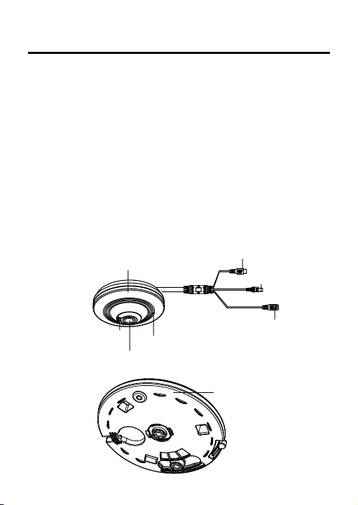
1 Introduction
Camera Body
Photoconductive
Resistance
Microphone
Audio Cable (Red)
HD TVI Cabl e (Gray)
12V DC Power Cable
Lens
Base Plate
1.1 Product Features
This series of camera adopts high performance sensor and
advanced circuit board design technology. It features high
resolution, low distortion, and low noise, etc. It is suitable for
surveillance system and image process system.
5 Megapixel high-performance CMOS
HD TVI output, up to 5Mega ` resolution
0.01Lux @ (F1.2,AGC ON), 0 Lux with IR
IR cut filter with auto switch
OSD menu
Built-in microphone, 1-ch audio output
1.2 Overview
Page 5

2 Installation
Before you start:
Please make sure that the device in the package is in good
condition and all the assembly parts are included.
Make sure that all the related equipment is power-off during
the installation.
Check the specification of the products for the installation
environment.
Check whether the power supply is matched with your
required output to avoid damage.
Please make sure the wall is strong enough to withstand three
times the weight of the camera and the mounting.
If the wall is the cement wall, you need to insert expansion
screws before you install the camera. If the wall is the wooden
wall, you can use self-tapping screw to secure the camera.
If the product does not function properly, please contact your
dealer or the nearest service center. Do not disassemble the
camera for repair or maintenance by yourself.
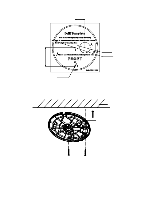
2.1 Ceiling Mounting
Steps:
1. Drill two screw holes and the cable hole according to the
supplied drill template.
Page 6
22
φ24
φ102
2-φ3.4
41.75
Ceiling
Base Plate
2. Align the screw holes and cable hole on the drill template and
the base plate, and then fix the base plate to the ceiling with
the two supplied screws.
mount.
mount.
Notes:
● For cement wall, you need to use the expansion screw to fix the
● For wooden wall, you can just use the self-tapping screw to fix the
3. Route the cables through the cable hole or the side opening
according to the actual needs, and connect the corresponding
Page 7
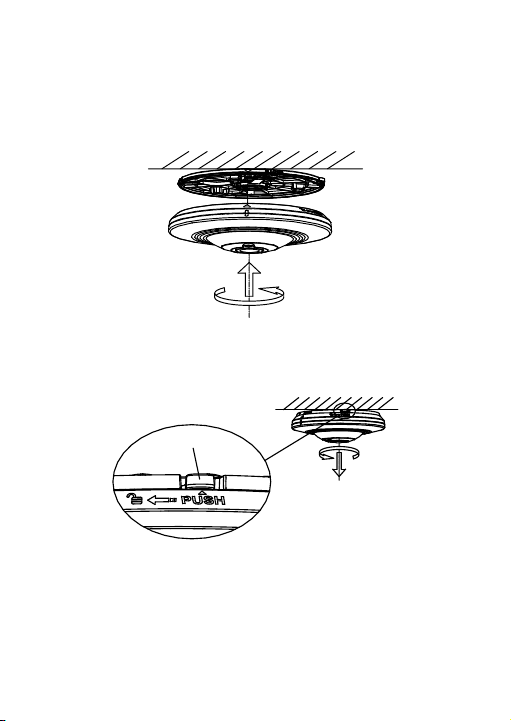
cables including power cable, network cable, audio and alarm
PUSH
cables, etc.
4. Align the triangle mark on the camera and base plate, and
then rotate the camera clockwise until it is locked up by the
three bayonet joints on the base plate.
5. To disassemble the camera: Press the Push button on the base
plate, rotate the camera anticlockwise, and then you can
remove the camera from the base plate.
6. To adjust the view angle: Rotate the camera body clockwise or
anticlockwise with the base plate, and then you can adjust the
camera to the desired view angle.
Page 8

15° 15°
2-26
φ24
φ102
2-φ3.4
41.75
83.5
2.2 Wall Mounting with a Slant Mounting Base
Before you start:
You need to purchase a slant mounting base separately if this
mounting method is selected.
Steps:
1. Drill two screw holes and the cable hole according to the
supplied drill template.
2. Fix the slant mounting base to the wall with the screws.
Page 9

Mounting B ase
Wall
3. Align the screw holes on the slant mounting base and the base
plate, and then secure the base plate on the slant mounting
base with the two supplied screws.
4. Route the cables through the cable hole or the side opening
according to the actual needs, and connect the corresponding
cables including power cable, network cable, audio and alarm
cables, etc.
5. Align the triangle mark on the camera and mounting base, and
then rotate the camera clockwise until it is locked up.
6. The installation is complete.
Page 10

PUSH
7. To disassemble the camera: Press the Push button on the base
plate, rotate the camera anticlockwise, and then you can
remove the camera from the base plate.
2.3 Wall Mounting with a Bracket
Before you start:
You need to purchase the bracket separately if this mounting
method is selected.
Steps:
1. Unfasten and remove the screw marked in the figure, and then
disassemble the bracket.
Page 11

Screw
Mounting B ase
2. Fix the mounting base to the wall with the screws.
Wall
3. Align the screw holes on the bracket and the base plate, and
then secure the base plate on the bracket with the two
supplied screws.
Page 12

4. Route the cables through the cable hole according to the
actual needs, and connect the corresponding cables including
power cable, network cable, audio and alarm cables, etc.
5. Align the triangle mark on the camera and base plate, and
then rotate the camera clockwise until it is locked up by the
three bayonet joints on the base plate.
6. Re-install the main body of the bracket to the mounting base,
and fix it with the screw.
7. To disassemble the camera, refer to the Step 5 in Section 2.1.
8. To adjust the view angle, refer to the Step 6 in Section 2.1.
Page 13

2.4 Pendant Mounting with a Bracket
Before you start:
You have to purchase the bracket separately if this mounting
method is selected.
Steps:
1. Fix the pendant bracket to the wall with the supplied M6×65
screws.
2. Aim the screwed hole on the camera at the top of the pendant
bracket, and then rotate the camera until it is secured tightly.
Page 14

3. Loosen the knob on the bracket and adjust the camera body to
Knob on the Bracket
Setup
INSTALLATION
DAY&NIGHT INFRARED
VIDEO
SETTINGS
CEILING
MOUNTING
DEFAULT
PANORAMA
4 PTZ
B/W
COLOR
SHARPNESS
MONITOR
LSC
VIDEO.
OUT
FISHEYE & 3 PTZ
ANNULAR
MINI-FISHEYE & 1 PTZ
ANNULAR & 2 PTZ
WALL
MOUNTING
DEFAULT
PANORAMA
4 PTZ
FISHEYE & 3 PTZ
MAIN MENU
AUTO
FACTORY
DEFAULT
EXIT
get the desired surveillance angle. Tighten the knob on bracket
to secure the camera.
3 Operation
3.1 Menu Description
Page 15

Notes:
● With a camera controller (purchased separately) or calling the preset
No. 95 of DVR you can select the menu and adjust the parameters.
● Move the cursor up/down/left/right with PTZ control panel to select
the menu item.
● Press the OK key or click Iris+ to confirm a selection.
3.2 INSTALLATION
The installation allows user to select different working
environments. If the camera is parallel to the ground, select
ceiling mounting as installation mode. If the camera is vertical to
the ground, select wall mounting as installation mode.
3.2.1 Ceiling Mounting
Ceiling mounting includes DEFAULT, PANORAMA, 4 PTZ, FISHEYE
& 3 PTZ, ANNULAR, MINI-FISHEYE & 1 PTZ, and ANNULAR & 2
PTZ.
Notes:
Any scene mode will be saved after being selected. The scene mode will be
the same once the device is powered off.
Page 16

DEFAULT
4 Panel PTZ
PTZ PANEL 1
SAVE & EXIT
RETURN
PTZ PANEL 2
PTZ PANEL 3
PTZ PANEL 4
Select DEFAULT to play live view in original view.
PANORAMA
Select PANORAMA to play live view after dewraping.
4 PTZ
Select 4 PTZ to play live view in 4 PTZ panel mode.
Move the cursor to select the PTZ panel to adjust and confirm.
Click up-left or up-right to rotate the PTZ panel. Click Zoom +/- to
zoom in/out the image.
FISHEYE & 3 PTZ
Select FISHEYE & 3 PTZ to play live view in one fisheye view and 3
PTZ panel mode.
Page 17

ANNULAR
ANNULAR
ANNULAR PANEL 1
SAVE & EXIT
RETURN
ANNULAR PANEL 2
Select ANNULAR to play live view in two annular panels of
after-dewraping image.
MINI-FISHEYE & 1 PTZ
Select DEFAULT to play live view in one fisheye mode and one
PTZ panel view.
You can control the PTZ of the PTZ panel view.
ANNULAR & 2 PTZ
Select ANNULAR to play live view in one annular panels of
after-dewraping image and two PTZ panel views.
3.2.2 Wall Mounting
Wall mounting includes DEFAULT, PANORAMA, 4PTZ, and
FISHEYE &3 PTZ.
Page 18

DEFAULT
MAIN MENU
DAY & NIGHT
SAVE & EXIT
RETURN
INFRARED
VIDEO SETTING
RESET MAIN MENU
AUTO/COLOR/BW
ON/OFF
Select DEFAULT to play live view in original view.
PANORAMA
Select PANORAMA to play live view after dewraping.
4 PTZ
Select 4 PTZ to play live view in 4 PTZ panel mode.
Move the cursor to select the PTZ panel to adjust and confirm. Click
up-left or up-right to rotate the PTZ panel. Click Zoom +/- to zoom in/out
the image.
FISHEYE & 3 PTZ
Select FISHEYE & 3 PTZ to play live view in one fisheye view and 3
PTZ panel mode.
3.3 MAIN MENU
3.3.1 DAY & NIGHT
Select DAY/NIGHT mode from AUTO/ COLOR/ BW.
Page 19

AUTO
VIDEO SETTING
RETURN
BRIGHTNESS
CONTRAST
SATURATION
50
50
50
The image switches between color mode and black/white mode
automatically.
COLOR
The image is colored in day mode all the time.
B/W
The image is black and white all the time.
3.3.2 INFRARED
Turn on/off the INFRARED by moving the cursor.
3.3.3 VIDEO SETTING
BRIGHTNESS
This feature is used to adjust brightness of the image. The value
ranges from 0 to 100.
CONTRAST
This feature enhances the difference in color and light between
parts of an image. The value ranges from 0 to 100.
Page 20

SATURATION
This feature is used to adjust color saturation of the image. The
value ranges from 0 to 100.
3.3.4 RESET MAIN MENU
Select RESET MAIN MENU to reset all parameters of main menu
to the default value.
3.3.5 SAVE & EXIT
Select SAVE & EXIT to save the settings and exit the menu.
3.4 FACTORY DEFAULT
Select RESET MAIN MENU to reset all settings of camera to the
default value.
3.5 EXIT
Select EXIT to exit the menu.
Page 21

 Loading...