

Page 1

Day/Night High-definition
Dome Camera
User Manual
V1.2.0
Page 2

Day/Night High-definition Dome Camera·User Manual
1
1
Thank you for purchasing our product. If there are any questions,
or requests, please do not hesitate to contact the dealer.
This manual applies to DS-2CC5181P-VP(IR)(H),
DS-2CC5191P-VP(IR)(H), DS-2CC51A1P-VP(IR)(H) dome
Camera.
This manual may contain several technical incorrect places or
printing errors, and the content is subject to change without notice.
The updates will be added to the new version of this manual. We
will readily improve or update the products or procedures
described in the manual.
DISCLAIMER STATEMENT
“Underwriters Laboratories Inc. (“UL”) has not tested the
performance or reliability of the security or signaling aspects of
this product. UL has only tested for fire, shock or casualty hazards
as outlined in UL’s Standard(s) for Safety, UL60950-1. UL
Certification does not cover the performance or reliability of the
security or signaling aspects of this product. UL MAKES NO
REPRESENTATIONS, WARRANTIES OR CERTIFICATIONS
WHATSOEVER REGARDING THE PERFORMANCE OR RELIABILITY
OF ANY SECURITY OR SIGNALING RELATED FUNCTIONS OF THIS
PRODUCT.”
Page 3

Day/Night High-definition Dome Camera·User Manual
2
2
Regulatory Information
FCC Information
FCC compliance: This equipment has been tested and found to
comply with the limits for a digital device, pursuant to part 15 of
the FCC Rules. These limits are designed to provide reasonable
protection against harmful interference when the equipment is
operated in a commercial environment. This equipment generates,
uses, and can radiate radio frequency energy and, if not installed
and used in accordance with the instruction manual, may cause
harmful interference to radio communications. Operation of this
equipment in a residential area is likely to cause harmful
interference in which case the user will be required to correct the
interference at his own expense.
FCC Conditions
This device complies with part 15 of the FCC Rules. Operation is
subject to the following two conditions:
1. This device may not cause harmful interference.
2. This device must accept any interference received, including
interference that may cause undesired operation
EU Conformity Statement
This product and - if applicable - the supplied
accessories too are marked with "CE" and comply
therefore with the applicable harmonized
European standards listed under the Low Voltage Directive
2006/95/EC, the EMC Directive 2004/108/EC.
Page 4

Day/Night High-definition Dome Camera·User Manual
3
3
2002/96/EC (WEEE directive): Products marked
with this symbol cannot be disposed of as unsorted
municipal waste in the European Union. For proper
upon the purchase of equivalent new equipment, or dispose of it at
designated collection points. For more information see:
www.recyclethis.info.
symbol, which may include lettering to indicate cadmium (Cd),
lead (Pb), or mercury (Hg). For proper recycling, return the battery
to your supplier or to a designated collection point. For more
information see: www.recyclethis.info.
recycling, return this product to your local supplier
2006/66/EC (battery directive): This product
contains a battery that cannot be disposed of as
unsorted municipal waste in the European Union.
See the product documentation for specific battery
information. The battery is marked with this
Page 5
Day/Night High-definition Dome Camera·User Manual
4
4
Safety Warnings and Cautions
Please pay attention to the following warnings and
cautions:
Hazardous Voltage may be present: Special
measures and precautions must be taken when
using this device. Some potentials (voltages) on the
should only be used by Employees from our company with
knowledge and training in working with these types of devices that
contain live circuits.
device may present a hazard to the user. This device
Power Supply Hazardous Voltage: AC mains voltages
are present within the power supply assembly. This device must be
connected to a UL approved, completely enclosed power supply, of
the proper rated voltage and current. No user serviceable parts
inside the power supply.
System Grounding (Earthing): To avoid shock, ensure
that all AC wiring is not exposed and that the earth grounding is
maintained. Ensure that any equipment to which this device will be
Page 6
Day/Night High-definition Dome Camera·User Manual
5
5
attached is also connected to properly wired grounded receptacles
and are approved medical devices.
Power Connect and Disconnect: The AC
power supply cord is the main disconnect device to
mains (AC power).The socket outlet shall be
accessible.
installed near the equipment and shall be readily
Installation and Maintenance: Do not connect/disconnect
any cables to or perform installation/maintenance on this device
during an electrical storm.
Power Cord Requirements: The connector
that plugs into the wall outlet must be a
grounding-type male plug designed for use in your
region. It must have certification marks showing certification by an
agency in your region. The connector that plugs into the AC
receptacle on the power supply must be an IEC 320, sheet C13,
female connector. See the following website for more information
http://kropla.com/electric2.htm.
Lithium Battery: Thi s device contains a Lithium Battery. There
is a risk of explosion if the battery is replaced by an incorrect type.
Dispose of used batteries according to the vendor’s instructions
and in accordance with local environmental regulations.
Page 7
Day/Night High-definition Dome Camera·User Manual
6
6
Perchlorate Material: Special handling may apply. See
www.dtsc.ca.gov/hazardouswaste/perchlorate. This notice is
required by California Code of Regulations, Title 22, Division 4.5,
Chapter 33: Best Management Practices for Perchlorate Materials.
This device includes a battery which contains perchlorate material.
Taiwan battery recycling:
Please recycle batteries.
Thermal and Mechanical Injury: Some
components such as heat sinks, power regulators,
to avoid contact with these components.
Electro Magnetic Interference: This equipment has not
been tested for compliance with emissions limits of FCC and similar
international regulations. This device is not, and may not be,
offered for sale or lease, or sold, or leased until authorization from
the United States FCC or its equivalent in other countries has been
obtained. Use of this equipment in a residential location is
prohibited. This equipment generates, uses and can radiate radio
frequency energy which may result in harmful interference to radio
communications. If this equipment does cause harmful
interference to radio or television reception, which can be
determined by turning the equipment on and off, the user is
required to take measures to eliminate the interference or
discontinue the use of this equipment.
and processors may be hot; care should be taken
Page 8
Day/Night High-definition Dome Camera·User Manual
7
7
Lead Content:
Please recycle this device in a responsible
manner. Refer to local environmental
regulations for proper recycling; do not dispose
of device in unsorted municipal waste.
Page 9
Day/Night High-definition Dome Camera·User Manual
8
8
Warnings Follow these
safeguards to prevent
serious injury or death.
Cautions Follow these
precautions to prevent
potential injury or material
damage.
Safety Instruction
These instructions are intended to ensure that user can use the
product correctly to avoid danger or property loss.
The precaution measure is divided into “Warnings” and “Cautions”
Warnings: Serious injury or death may occur if any of the
warnings are neglected.
Cautions: Injury or equipment damage may occur if any of the
cautions are neglected.
Warnings
Please adopt the power adapter which can meet the safety
extra low voltage (SELV) request. And source with DC 12V or
AC 24V (depending on models) according to the IEC60950-1
and Limited Power Source standard.
If the product does not work properly, please contact your
dealer or the nearest service center. Never attempt to
disassemble the camera yourself. (We shall not assume any
Page 10
Day/Night High-definition Dome Camera·User Manual
9
9
responsibility for problems caused by unauthorized repair or
maintenance.)
To reduce the risk of fire or electrical shock, do not expose this
product to rain or moisture.
This installation should be made by a qualified service person
and should conform to all local codes.
Please install blackouts equipment into the power supply
circuit for convenient supply interruption.
Please make sure that the ceiling can support more than 50(N)
Newton gravities if the camera is fixed to the ceiling.
Cautions
Make sure the power supply voltage i s correct before using the
camera.
Do not drop the camera or subject it to physical shock.
Do not touch sensor modules with fingers. If cleaning is
necessary, use a clean cloth with a bit of ethanol and wipe it
gently. If the camera will not be used for an extended period of
time, put on the lens cap to protect the sensor from dirt.
Do not aim the camera at the sun or extra bright places. A
blooming or smear may occur otherwise (which is not a
malfunction however), and affecting the endurance of sensor
at the same time.
Page 11

Day/Night High-definition Dome Camera·User Manual
10
10
The sensor may be burned out by a laser beam, so when any
laser equipment is being used, make sure that the surface of
the sensor will not be exposed to the laser beam.
Do not place the camera in extremely hot or cold temperatures
(the operating temperature should be between -10°C ~ 60°C ,
dusty or damp locations, and do not expose it to high
electromagnetic radiation.
To avoid heat accumulation, good ventilation is required for a
proper operating environment.
Do not let water and any liquid flow into the camera.
While shipping, the camera should be packed in its original
packing, or packing of the same texture.
Improper use or replacement of the battery may result in
hazard of explosion. Replace with the same or equivalent type
only. Dispose of used batteries according to the instructions
provided by the battery manufacturer.
Page 12

Day/Night High-definition Dome Camera·User Manual
11
11
Table of Contents
1 Introduction .................................................................. 1
1.1 Product Features ..................................................1
1.2 Function Summary ...............................................2
1.3 Overview .............................................................5
2 Installation ................................................................... 6
2.1 Disassembling ......................................................6
2.2 Mounting .............................................................7
2.2.1 Ceiling Mounting ..........................................7
2.2.2 In-ceiling Mounting with gang box ................ 10
2.2.3 In-ceiling Mounting without gang box ........... 13
2.2.4 Outdoor Wall Mounting ............................... 16
2.2.5 Indoor Wall Mounting .................................. 20
2.3 Image and Focus Adjusting .................................. 22
3 Menu Description ........................................................ 25
3.1 MAIN MENU ....................................................... 25
3.2 LENS Setting...................................................... 26
3.3 SHUTTER/AGC Setting......................................... 27
3.4 WHITE BALANCE Setting ..................................... 29
3.5 BACKLIGHT Setting ............................................ 32
3.6 PICTURE ADJUST Setting ..................................... 33
3.7 ATR Setting ....................................................... 34
3.8 MOTION DETECTION Setting ................................ 35
3.9 PRIVACY MASK Setting ........................................ 38
3.10 DAY/NIGHT Setting ........................................... 39
3.11 NR Setting ....................................................... 41
3.12 CAMERA ID Setting ........................................... 42
3.13 SYNC/PIXEL CORRECT Setting ............................ 44
Page 13

Day/Night High-definition Dome Camera·User Manual
12
12
3.14 LANGUAGE Setting............................................ 45
3.15 CAMERA RESET Setting ..................................... 45
Appendix ........................................................................ 46
Table 1 DS-2CC5181P(N)-VP(IR)(H) ........................... 46
Table 2 DS-2CC5191P(N)-VP(IR)(H) ........................... 50
Table 3 DS-2CC51A1P(N)-VP(IR)(H) ........................... 54
Page 14

Day/Night High-definition Dome Camera·User Manual
1
1
1 Introduction
1.1 Product Features
This camera adopts high performance CCD and advanced print
circuit board design technology. It possesses of high resolution,
low distortion, and low noise features, etc. It is extremely suitable
for supervisory system and image process system.
Adopt high performance SONY CCD, and supply high definition
and clear image, up to 700TVL
Low illumination, Color: 0.001Lux@F1.2, B/W:
0.0001Lux@F1.2
Support ICR filter auto switch
Support OSD menu controlling, enable user to configure the
detail parameters
Adopt advanced stepping motor and sleep mode to avoid ICR
oscillation
Support auto white balance with high color rendition
High SNR give rise to clear and pleased image
Support SMART IR
Support auto electronic shutter control to adapt to different
environments
Support auto gain control, adaptive brightness
Support auto iris
Page 15

Day/Night High-definition Dome Camera·User Manual
2
2
Support Privacy mask with 8 optional colors and 8 configurable
areas
Advanced design technology with high reliability
Advanced 3-axis design allows this dome camera to be
adjusted 0-355° horizontally and 0-180° vertically to meet
different mounting requirements
Adopt advanced double-plate design to guarantee the heat
dissipation of the CCD and image quality
Impact Protection: IEC60068-2-75 test, Eh, 50J; EN50102, up
to IK10
Weather proof rating: IP66
1.2 Function Summary
Motion Detection: In the user-defined motion detection
surveillance area, the moving object can be detected and trigger
alarm. The sensitive level can be customized according to the
environment.
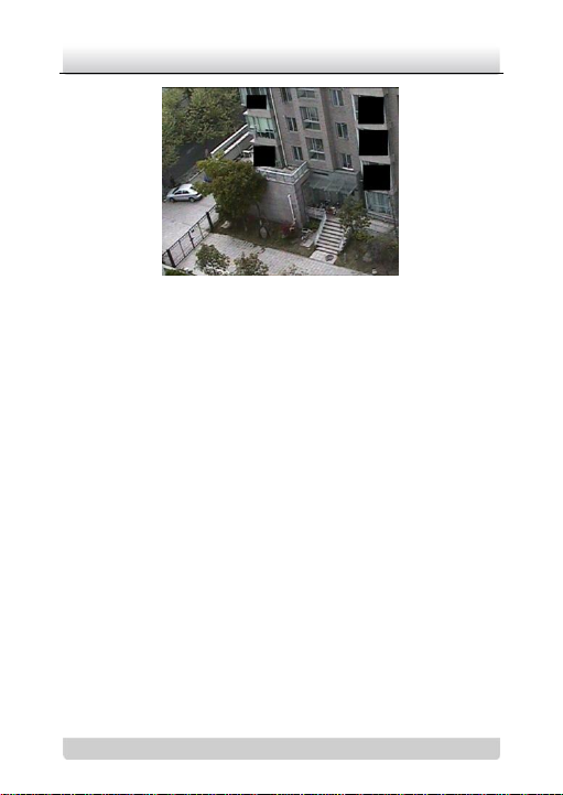
Privacy Mask: This function allows you to block or mask certain
area of a scene, thus prevent the personal privacy from recording
or live viewing.
Page 16
Day/Night High-definition Dome Camera·User Manual
3
3
Figure 1-1 Privacy Mask
DAY/NIGHT Auto Switch: The cameras deliver color images
during the day. And as light diminishes at night, the cameras
switch to night mode and deliver black and white images with high
quality.
AGC: AGC is a control circuit that automatically changes the gain
of a receiver or other piece of equipment, so that the desired
output signal remains essentially. When under low illumination,
AGC will regulate the gain and amplification of the video signal.
S/N ratio: It is the ratio of Signal voltage and noise voltage. The
ratio is larger, the effect of noise is less, and the image is clearer.
OSD (On Screen Display): The on-screen display (abbreviated
OSD) is an image superimposed on a screen picture, used for
displaying information and menu.
Synchronous System: Synchronization of the camera usually
contains power synchronization and internal synchronization.
Page 17
Day/Night High-definition Dome Camera·User Manual
4
4
Internal synchronization is realized by the synchronous signal
which is generated by the inside crystal oscillator.
White Balance: White balance can remove the unrealistic color
casts. White balance is the white rendition function of the camera
to adjust the color temperature according to the environment
automatically.
ICR Auto Switch: The filter will filter infrared light during the
daytime and change to normal filter at night to ensure a high
sensitivity and clear image.
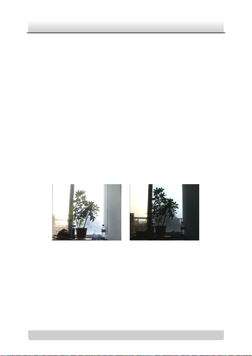
BLC: If you focus on an object against strong backli ght, the object
will be too dark to be seen clearly. The BLC (Backlight
Compensation) function can compensate light to the object in the
front to make it clear, but this causes the over-exposure of the
background where the light is strong.
Figure 1-2 BLC OFF and BLC ON
Page 18

Day/Night High-definition Dome Camera·User Manual
5
5
1.3 Overview
Figure 1-3 Dome Overview
Page 19
Day/Night High-definition Dome Camera·User Manual
6
6
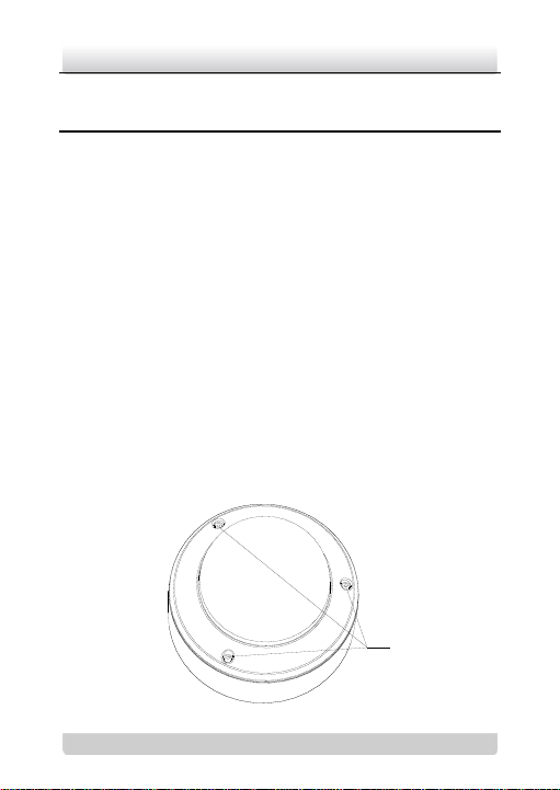
Screws
2 Installation
Before you start:
Please make sure that the device in the package is in good
condition and all the assembly parts are included.
Note: Please ensure that the wall is strong enough to withstand
three times the weight of the camera. If the wall is not strong
enough, the camera may fall and cause serious damage.
2.1 Disassembling
Steps:
1. Loosen the three screws on the edge of the lower dome with
the supplied screw driver.
2. Loosen the screw that secures the leash of the lower dome to
the camera. Remove the lower dome.
3. Remove the inner black liner.
Page 20
Day/Night High-definition Dome Camera·User Manual
7
7
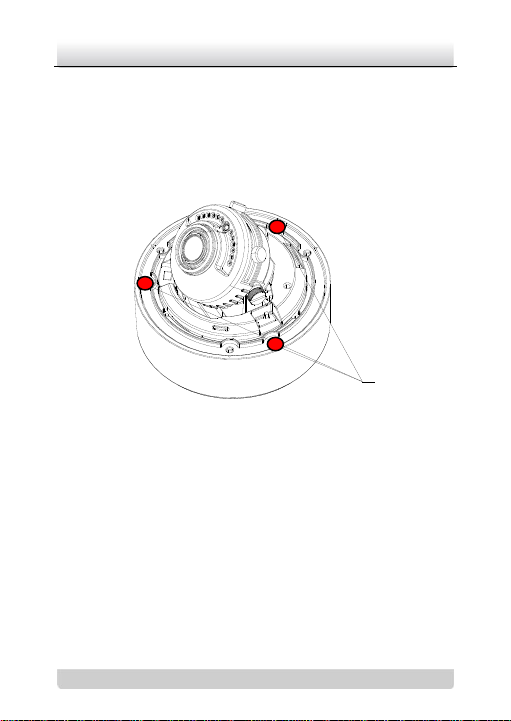
Set Screws
Figure 2-1 Removing the Lower Dome
4. Loosen the three screws as shown in Figure 2-2 with the
supplied screw driver.
5. Remove the camera from the back box.
Figure 2-2 Removing the Camera
2.2 Mounting
2.2.1 Ceiling Mounting
Steps:
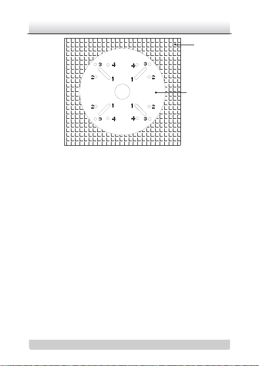
1. Attach the drill template (supplied) to the place where you
want to fix the camera.
2. According to the circles on the drill template as shown in Figure
2-3, drill screws holes in the ceiling on your demand.
Page 21
Day/Night High-definition Dome Camera·User Manual
8
8
Drill Template
Ceiling
Figure 2-3 The Drill Template
3. If you want to route the cables inside the ceiling, drill a hole in
the ceiling according to the circle in the centre of the template.
Skip this step, if you want to route the cables on the surface of
the ceiling.
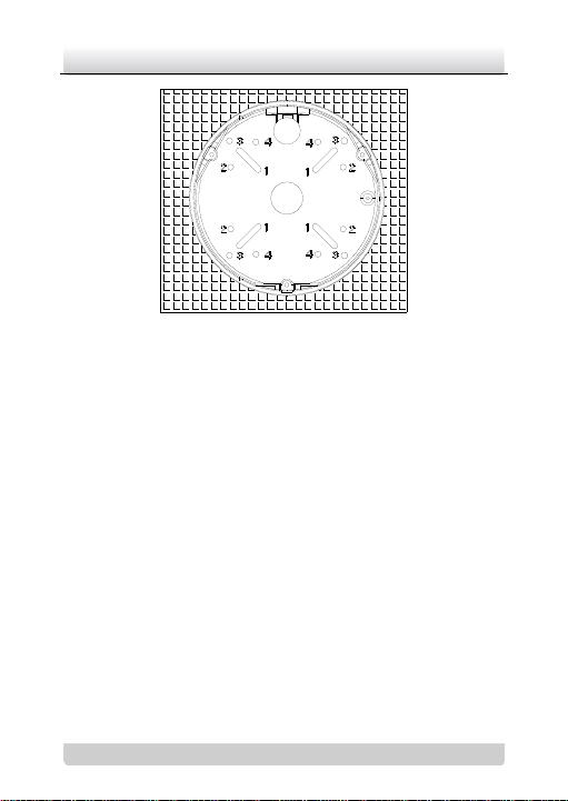
4. Attach the back box to the ceiling by aligning the holes of the
back box with the holes on the drill template.
5. Secure the back box with the supplied screws as shown in
Figure 2-4.
Page 22
Day/Night High-definition Dome Camera·User Manual
9
9
Figure 2-4 Securing Back box
6. Route the cables through the hole in the center of the drill
template.
7. Align the camera with the back box.
8. Tighten the set screws to secure the camera with the back box.
9. Connect the video output connector to the monitor. Connect
the power connector to the power supply.
10. Adjust the image and focus. Please refer to the section 2.3 for
more detailed information.
11. Install the inner black liner back to the camera.
12. Tighten the screws to secure the lower dome with the back
box.
Page 23

Day/Night High-definition Dome Camera·User Manual
10
10
Figure 2-5 Securing Lower Dome
2.2.2 In-ceiling Mounting with gang box
Steps:
1. Install the gang junction box in the ceiling.
2. Attach the In-ceiling Mount (supplied) to the gang junction box
with two screws.
Page 24

Day/Night High-definition Dome Camera·User Manual
11
11
In-ceiling Mount
Gang Box
Ceiling
Figure 2-6 In-ceiling Mount
3. Route the cables through the hole in the center of the in-ceiling
mount.
4. Align the camera with the gang junction box.
5. Tighten the screws to secure the camera with the gang
junction box.
6. Connect the video output connector to the monitor. Connect
the power connector to the power supply.
7. Adjust the image and focus. Please refer to the section 2.3 for
more detailed information.
Page 25

Day/Night High-definition Dome Camera·User Manual
12
12
Gang Box
Ceiling
In-ceiling Mount
Camera
Ceiling
Figure 2-7 Securing Camera
8. Install the inner black liner back to the camera.
9. Align the lower dome with the in-ceiling mount.
10. Tighten the screws to secure the lower dome with the in-ceiling
mount.
Figure 2-8 Securing Lower Dome
Page 26

Day/Night High-definition Dome Camera·User Manual
13
13
Ceiling
Drill Template
2.2.3 In-ceiling Mounting without gang box
Steps:
1. Attach the drill template (supplied) to the place where you
want to fix the camera.
2. According to the circles on the drill template as shown in Figure
2-9, drill screws holes in the ceiling on your demand.
Figure 2-9 The Drill Template
3. Rotate the three screws through the screw holes of the
in-ceiling mount.
4. Rotate the spring clips counterclockwise to the screws as
shown in Figure 2-10.
5. Push the three spring clips through the three screw holes in the
ceiling.
Page 27

Day/Night High-definition Dome Camera·User Manual
14
14
In-ceiling Mount
Spring Clips
6. Tighten the screws. Then rotate the spring clips
counterclockwise to tightly secure the in-ceiling mount with
the ceiling.
Figure 2-10 The In-ceiling Mount
7. Route the cables through the hole in the center of the in-ceiling
mount.
8. Align the camera with the in-ceiling mount.
9. Tighten the set screws to secure the camera with the in-ceiling
mount.
10. Connect the video output connector to the monitor. Connect
the power connector to the power supply.
11. Adjust the image and focus. Please refer to the section 2.3 for
more detailed information.
Page 28

Day/Night High-definition Dome Camera·User Manual
15
15
Figure 2-11 Securing Camera
12. Install the inner black liner back to the camera.
13. Align the lower dome with the in-ceiling mount.
14. Tighten the screws to secure the lower dome with the in-ceiling
mount.
Figure 2-12 Securing Lower Dome
Page 29

Day/Night High-definition Dome Camera·User Manual
16
16
Front Panel
Set Screws
2.2.4 Outdoor Wall Mounting
For the wall mounting, you have to purchase a wall mount.
Steps:
1. Secure the wall mount to the wall.
2. Loosen the three set screws on the edge of the front panel.
Remove the front panel.
Figure 2-13 Removing the Front Panel
3. Route the cables through the hole in the center of the wall
mount.
4. Align the camera with the wall mount.
5. Tighten the set screws to secure the camera with the wall
mount.
6. Connect the video output connector to the monitor. Connect
the power connector to the power supply.
Page 30

Day/Night High-definition Dome Camera·User Manual
17
17
7. Adjust the image and focus. Please refer to the section 2.3 for
more detailed information.
Figure 2-14 Securing Camera
8. Install the inner black liner back to the camera.
9. Align the lower dome with the camera.
10. Tighten the screws to secure the lower dome with the camera.
Page 31

Day/Night High-definition Dome Camera·User Manual
18
18
Figure 2-15 Securing Lower Dome
11. Tighten the set screws to secure the front panel to the mount.
Page 32

Day/Night High-definition Dome Camera·User Manual
19
19
DS-1242ZJ
DS-1243ZJ
Figure 2-16 Securing Front Panel
The DS-1242ZJ and DS-1243ZJ mounts are shown as follows:
Page 33

Day/Night High-definition Dome Camera·User Manual
20
20
2.2.5 Indoor Wall Mounting
For the wall mounting, you have to purchase a wall mount.
Steps:
1. Align the number 2 holes of the back box with the number 1
holes of the wall mount.
2. Secure the back box to the wall mount with four screws.
Figure 2-17 Securing Back Box
3. Route the cables through the hole in the center of the wall
mount.
4. Align the camera with the back box.
5. Tighten the set screws to secure the camera with the back box.
6. Connect the video output connector to the monitor. Connect
the power connector to the power supply.
Page 34

Day/Night High-definition Dome Camera·User Manual
21
21
7. Adjust the image and focus. Please refer to the section 2.3 for
more detailed information.
Figure 2-18 Securing Camera
8. Install the inner black liner back to the camera.
9. Align the lower dome with the camera.
10. Tighten the screws to secure the lower dome with the camera.
Page 35

Day/Night High-definition Dome Camera·User Manual
22
22
DS-1229ZJ
DS-1239ZJ
Figure 2-19 Securing Lower Dome
The DS-1229ZJ and DS-1239ZJ mounts are shown as follows:
2.3 Image and Focus Adjusting
Steps:
1. Three-axis adjustment.
1). View the camera image using the monitor.
2). Rotate the panning table to adjust the panning position of
the camera.
3). Loosen the tilting lock screw.
4). Rotate the tilting table to adjust the tilting position of the
camera.
5). Tighten the tilting lock screw.
6). Rotate the lens to adjust the azimuth angle of the image.
Page 36

Day/Night High-definition Dome Camera·User Manual
23
23
Pan
Rotation
Tilt
Tilting Lock Screw
Figure 2-20 Three-axis Adjustment
2. Zoom and focus adjustment.
1). View the camera image using the monitor.
2). Loosen the zoom lock screw and move the screw between
T(Tele) and W(Wide) to obtain the appropriate angle of
view.
3). Tighten the zoom lock screw.
4). Loosen the focus lock screw and move the screw between
F(Far) and N(Near) to obtain the optimum focus.
5). Tighten the focus lock screw.
Page 37

Day/Night High-definition Dome Camera·User Manual
24
24
Auxiliary Video
Output Connector
Tilting Lock Screw
Zoom Lock Screw
Focus Lock Screw
Menu Button
Menu Button
Figure 2-21 Lens Adjustment
Page 38

Day/Night High-definition Dome Camera·User Manual
25
25
SETUP MENU
LENS AUTO8
SHUTTER/AGC AUTO8
WHITE BAL ATW8
BACKLIGHT OFF
PICT ADJUST 8
ATR OFF
MOTION DET OFF
PRIVACY OFF
DAY/NIGHT AUTO8
NR 8
CAMERA ID OFF/ON8
SYNC INT
LANGUAGE ENGLISH
CAMERA RESET
EXIT8 SAVE ALL
3 Menu Description
3.1 MAIN MENU
Steps:
1. Press the button to access the main menu or the submenu.
2. Set the menu button up/down to position the cursor.
3. Set the menu button left/right to select the different options.
Figure 3-1 Main Menu
Page 39

Day/Night High-definition Dome Camera·User Manual
26
26
AUTO IRIS
TYPE DC
MODE AUTO
SPEED - - - | - - - 080
RETURN8
TYPE
The type is DC.
MODE
Choose the iris mode. AUTO, OPEN and
CLOSE are selectable
SPEED
Adjust the auto iris speed. The higher the
number, the faster the auto iris. The value
ranges from 0 to 255.
3.2 LENS Setting
After moving the cursor to LENS, set the menu button up/down to
select MANUAL or AUTO.
Selecting MANUAL mode, you have to adjust the LENS IRIS
manually.
Selecting AUTO mode, press the button to enter the AUTO IRIS
submenu.
Figure 3-2 AUTO IRIS
AUTO IRIS function can automatically open and closes the iris in
response to changing light conditions.
Page 40

Day/Night High-definition Dome Camera·User Manual
27
27
MANUAL SETUP
MODE SHUT+AGC
SHUTTER 1/50
AGC 6.00
RETURN8
SHUTTER
Manually set the shutter speed. 1/50,
1/100, 1/250, 1/500, 1/1k, 1/2k, 1/4k,
3.3 SHUTTER/AGC Setting
SHUTTER/AGC allows you to adjust how the system balances
SHUTTER and AGC settings in different light conditions. You can
set the different shutter and AGC value according to the luminance
level of the situation.
You can choose MANUAL and AUTO mode for the shutter and
AGC.
Note: When in the lens setting interface, choosing lens type as
AUTO, the AUTO IRIS can also be adjusted to change the
brightness of the image; otherwise only shutter and AGC are
adjustable.
Figure 3-3 MANUAL SETUP
In the MANUAL SETUP submenu, you can adjust the SHUTTER
speed and AGC value to maintain the brightness level of the
camera.
Page 41

Day/Night High-definition Dome Camera·User Manual
28
28
1/100k are selectable.
AGC
The AGC value can be set between 6 and
44.8.
AUTO SETUP
HIGH LUMINANCE
MODE SHUT+AUTO IRIS/AUTO IRIS
BRIGHTNESS - - - | - - - 080
LOW LUMINANCE
MODE AGC
BRIGHTNESS *0.50
RETURN8
MODE
SHUT+AUTO IRIS and AUTO IRIS
are available when the LENS type is
AUTO IRIS. When the LENS type is
Manual, the iris is fixed and only SHUT
Figure 3-4 AUTO SETUP
In the AUTO SETUP submenu (Figure 3-4), you can adjust the
BRIGHTNESS value. The system will automatically adjust the
SHUTTER, AGC and AUTO IRIS settings according to the
BRIGHTNESS setting. And the system can define and recognize
the lumination level automatically.
In HIGH LUMINANCE condition, the SHUTTER speed and AUTO
IRIS level can be modified automatically according to the
BRIGHTNESS value.
Page 42

Day/Night High-definition Dome Camera·User Manual
29
29
option is provided.
BRIGHTNESS
The value ranges from 0 to 255.
MODE
Only AGC is available.
BRIGHTNESS
×1.00, ×0.75, ×0.50 and ×0.25 are
selectable.
In LOW LUMINANCE condition, the AGC can be adjusted
automatically according to the BRIGHTNESS value.
3.4 WHITE BALANCE Setting
This feature processes the viewed image to retain color balance
over a color temperature range and remove the unrealistic color
casts. ATW, PUSH, PUSH LOCK, USER1, USER2, ANTI CR and
MANUAL are selectable.
PUSH
Selecting the PUSH mode, the viewed image retains color balance
automatically. The color in the image balances according to the
color temperature.
PUSH LOCK
Selecting the PUSH LOCK mode and pressing the button, the
viewed image retains color balance automatically according to the
current color temperature of the scene. The color balance value
doesn’t change according to the color temperature.
ANTI CR (Anti Color Rolling)
Page 43

Day/Night High-definition Dome Camera·User Manual
30
30
B-GAIN
It’s used to adjust the picture output in the
blue range.
The B-GAIN value ranges from 0 to 255.
R-GAIN
It’s used to adjust the picture output in the
red range.
The R-GAIN value ranges from 0 to 255.
USER1 WB
B-GAIN - - - | - - - 030
R-GAIN - - - | - - - 033
RETURN8
B-GAIN
The B-GAIN value ranges from 0 to 255.
Selecting this feature, the system suppresses the color rolling
under the fluorescent light when processing the color balance.
USER 1
This mode is the indoor mode. It is suitable for indoor application.
Figure 3-5 USER 1 WB
USER 2
This mode is suitable for environment with the fluorescent light.
Page 44

Day/Night High-definition Dome Camera·User Manual
31
31
R-GAIN
The R-GAIN value ranges from 0 to 255.
MANUAL WB
LEVEL - - - | - - - 064
RETURN8
SPEED
The SPEED can be set from
0 to 255.
MANUAL
Selecting MANUAL and pressing the button to enter the MANUAL
WB submenu. Customize the LEVEL value on your demand.
Figure 3-6 MANUAL WB
ATW
Auto Tracking White Balance
In ATW mode, white balance is continuously being adjusted in
real-time according to the color temperature of the scene
illumination.
Page 45

Day/Night High-definition Dome Camera·User Manual
32
32
DELAY CNT
It’s the delay time between
monitoring the light
conditions changing and
adjusting the white balance.
ATW FRAME
It’s used to adjust the image
size of the ATW image. ×
0.50, ×1.00, ×1.50 and ×
2.00 are available.
ENVIRONMENT
INDOOR and OUTDOOR are
selectable.
ATW
SPEED - - - | - - - 239
DELAY CNT - - - | - - - 016
ATW FRAME *1.00
ENVIRONMENT INDOOR
RETURN8
Figure 3-7 ATW
3.5 BACKLIGHT Setting
SHUTTER/AGC allows you to adjust the backlight. There are OFF,
BLC and HLC selectable.
BLC (Backlight Compensation)
Page 46

Day/Night High-definition Dome Camera·User Manual
33
33
If there’s a strong backlight, the object in front of the backlight
appears silhouetted or dark. BLC can correct the exposure of the
subject. But the backlight environment is overexposed.
HLC(Highlight Compensation)
HLC masks strong light sources that usually flare across a scene.
This makes it possible to see the detail of the image that would
normally be hidden.
3.6 PICTURE ADJUST Setting
Move the cursor to PICT ADJUST. Press the button to enter the
PICT ADJUST submenu. The adjustable features are MIRROR,
BRIGHTNESS, CONTRAST, SHARPNESS, HUE, and GAIN.
MIRROR
If you turn the MIRROR function on, the image will be flipped
horizontally. It is like the image in the mirror.
BRIGHTNESS
The brightness is adjustable from 0 to 255.
CONTRAST
This feature enhances the difference in color and light between
parts of an image. The value ranges from 0 to 255.
SHARPNESS
SHARPNESS describes the clarity of detail in the image. The value
ranges from 0 to 255.
HUE
Page 47

Day/Night High-definition Dome Camera·User Manual
34
34
PICT ADJUST
MIRROR OFF
BRIGHTNESS - - - | - - - 000
CONTRAST - - - | - - - 128
SHARPNESS - - - | - - - 128
HUE - - - | - - - 128
GAIN - - - | - - - 128
RETURN8
Adjust this feature to change the color of the image. The value
ranges from 0 to 255.
GAIN
Adjust this feature to change the depth of the color. The value
ranges from 0 to 255.
Figure 3-8 PICT ADJUST
3.7 ATR Setting
ATR is the digital dynamic range function which can adjust the
brightness and contrast level of the image, and balance the
brightness level of the whole image. Move the cursor to ATR. Set
the button left/right to select ON or OFF. After selecting ON, press
the button to enter the ATR submenu.
Page 48

Day/Night High-definition Dome Camera·User Manual
35
35
LUMINANCE
There are MID, HIGH, LOW selectable,
standing for middle, high and low
luminance respectively.
CONTRAST
There are MID, HIGH, LOW, MIDLOW and
MIDHIGH selectable.
ATR
LUMINANCE LOW
CONTRAST LOW
RETURN8
Figure 3-9 ATR
3.8 MOTION DETECTION Setting
There are two kinds of MOTION DET panes, BLOCKDISP and
MONITOR AREA.
BLOCK DISP
Steps:
1. After moving the cursor to MOTION DET, select ON and press
the button to enter the submenu.
Page 49

Day/Night High-definition Dome Camera·User Manual
36
36
2. Position the cursor on DETECT SENSE, set the menu button
left/right to adjust the sensitivity level.
3. Position the cursor on BLOCK DISP, set the menu button
left/right to select ENABLE.
4. Press the button to enter the setup interface of the detection
panes.
5. You can press the button once to cancel a pane. Press on the
pane again to enable the pane.
6. Long press the button to back to the previous menu.
7. Select ON to enable BLOCK DISP.
8. Move the cursor to MONITOR AREA and select ON.
9. Return to the MAIN MENU and click SAVE ALL.
10. You can find the BLOCK DISP take effect after you exit the
main menu.
MONITOR AREA
Steps:
1. After moving the cursor to MOTION DET, select ON and press
the button to enter the submenu.
2. Position the cursor on DETECT SENSE, set the menu button
left/right to adjust the sensitivity level.
3. Position the cursor on MONITOR AREA. Select OFF to disable
area motion detection. Select ON to enable area motion
detection.
Page 50

Day/Night High-definition Dome Camera·User Manual
37
37
MOTION DET
DETECT SENSE - - - | - - - 111
BLOCK DISP OFF
MONITOR AREA ON
AREA SEL 1/4
TOP - - - | - - - 000
BOTTOM - - - | - - - 000
LEFT - - - | - - - 000
RIGHT - - - | - - - 000
RETURN8
4. Position the cursor on AREA SEL to select one area. There are
four areas available.
5. Set the values of TOP, BOTTOM, LEFT and RIGHT. The size
and position of the area is defined by these values. And after
you set all this value, you can see a frame on the image.
6. Return to the MAIN MENU and click SAVE ALL.
7. You can find the MONITOR AREA frame take effect after you
exit the main menu.
Note: The MONITOR AREA frame take effect, only when there
are BLOCK DISP panes in the MONITOR AREA frame.
Note: The MONITOR AREA mode and the BLOCK DISP mode
can exist simultaneously.
Figure 3-10 MOTION DET
Page 51

Day/Night High-definition Dome Camera·User Manual
38
38
AREA SEL
There are four areas available.
COLOR
There are eight colors available.
TRANSP
The available values are 1.0, 0.75, 0.5, and 0.
3.9 PRIVACY MASK Setting
This feature allows you to cover certain areas which you don’t want
to be viewed or recorded.
The size, color, transparency of the areas is adjustable.
Steps:
1. After moving the cursor to PRIVACY, press the button to enter
PRIVACY submenu.
2. Select one privacy area in AREA SEL.
3. Set the values of TOP, BOTTOM, LEFT and RIGHT. The size
and position of the area is defined by these values.
4. Select the color and the transparency values for the privacy
area. Turn the MOSAIC on if you want mosaic privacy areas.
5. Repeat the steps 1 through 4 to program other privacy areas.
Note: there are only 4 areas available in AREA SEL, when the
MOTION DETECTION function is on.
Page 52

Day/Night High-definition Dome Camera·User Manual
39
39
PRIVACY
AREA SEL 1/8
TOP - - - | - - - 000
BOTTOM - - - | - - - 000
LEFT - - - | - - - 000
RIGHT - - - | - - - 000
COLOR 1
TRANSP 0.00
MOSAIC OFF
RETURN8
Figure 3-11 PRIVACY
3.10 DAY/NIGHT Setting
There are five DAY/NIGHT modes selectable: AUTO, COLOR,
and B/W.
COLOR mode is used for normal lighting conditions.
B/W mode can increase the sensitivity in low light conditions.
AUTO Mode Setting
In AUTO mode, the day mode and the night mode can switch
automatically.
Steps:
Page 53

Day/Night High-definition Dome Camera·User Manual
40
40
BURST
Select ON or OFF to enable or disable
this feature.
DELAYCNT
The value ranges from 0 to 255. This
value is the delay time before the
day/night mode switches.
DAYNIGHT
The value ranges from 0 to 255. The day
mode switches to the night mode when
the light condition reaches to the value
you select.
NIGHTDAY
The value ranges from 0 to 255. The
night mode switches to the day mode
when the light condition reaches to the
value you select.
DAY/NIGHT
BURST OFF
DELAY CNT - - - | - - - 000
DAY→NIGHT - - - | - - - 003
NIGHT→DAY - - - | - - - 005
RETURN8
1. After moving the cursor to DAY/NIGHT, set the menu button
left/right to select AUTO.
2. Press the button to enter the submenu.
Figure 3-12 DAY/NIGHT
Page 54

Day/Night High-definition Dome Camera·User Manual
41
41
B/W
BURST OFF
RETURN8
Y LEVEL
The value ranges from 0 to 15.
B/W Mode Setting
In the B/W submenu, you can enable or disable the BURST.
Figure 3-13 B/W
3.11 NR Setting
This feature is used to reduce the noise in the video signal.
After moving the cursor to NR, press the button to enter the NR
submenu.
Page 55

Day/Night High-definition Dome Camera·User Manual
42
42
NR
Y LEVEL - - - | - - - 004
RETURN8
Figure 3-14 NR
3.12 CAMERA ID Setting
In Camera ID submenu, you can customize the camera ID. It also
allows you to adjust the camera ID position on the monitor screen.
Select OFF, if you want to disable the Camera ID.
Select ON, if you want to enable the Camera ID.
Customizing the camera ID
Steps:
1. After selecting ON, press the button to enter the submenu.
2. Set the menu button up/down/left/right to position the cursor
on the character you want.
Note: The characters include letters, numbers and symbols.
3. Set confirm to enter your selection. The selected character
displays under the CAMERA ID and above the characters.
Page 56

Day/Night High-definition Dome Camera·User Manual
43
43
4. Repeat the steps 1 through 3 to select other characters.
Modifying the camera ID
Steps:
1. Position the cursor on one of the arrows.
2. Press the button to position the cursor on the character that
needs to modify.
3. Select one of the other characters to replace it.
Clearing the camera ID
Steps:
1. Position the cursor on CLR.
2. Press the button to clear the characters.
Positioning the camera ID
Steps:
1. After moving the cursor to POS, press the button to enter the
position setting interface.
2. Set the menu button up/down/left/right to position the camera
ID.
3. Press the button to save the position and exit.
Page 57

Day/Night High-definition Dome Camera·User Manual
44
44
CAMERA ID
ABCDEFGHIJKLMNOPQRSTUV
WXYZ0123456789-!”#$%&’
()_`,¥:;<=>?@\^*.x+/
CHR1 CHR2
← → ↑ ↓ CLR POS8
RETURN8
Figure 3-15 CAMERA ID
3.13 SYNC/PIXEL CORRECT Setting
Both internal and line l ock synchronization are available. (Only the
camera which supports DC 12 V and AC 24 V power has line lock
synchronization.)
If 12V DC power supply is applied, SYNC mode is internal
synchronization and not adjustable.
If 24V AC power supply is applied, you can select either
internal or line lock synchronization.
Press the button to right for about 2seconds, you can exchange
the SYNC mode. Then get to the menu of the SYNC setting,
you can adjust the phase of the Line-lock.
Press the button to left for about 2 seconds; you can enable
auto PIXEL CORRECT function. This function will be more
active in the absolutely dark environment. Make sure that the
lens’s IRIS is closed before using this function.
Page 58

Day/Night High-definition Dome Camera·User Manual
45
45
3.14 LANGUAGE Setting
You can adjust the language of the on-screen menu. The factory
default language is English.
Steps:
1. Move the cursor to LANGUAGE.
2. Set left/right to select the language you need.
3.15 CAMERA RESET Setting
After moving the cursor to CAMERA RESET, press the button to
reset all camera settings to factory default parameters.
Page 59

Day/Night High-definition Dome Camera·User Manual
46
46
Model
Parameter
DS-2CC5181P(N)-VP(IR)(H)
600 TVL CCD ICR Weather-proof Vandal-proof
Dome Camera
Camera
Image Sensor
1/3” SONY Super HAD CCD II
Signal System
PAL/NTSC
Effective Pixels
PAL: 752 (H) × 582 (V)
NTSC: 768 (H) × 494 (V)
Min. Illumination
Color: 0.001 Lux @ (F1.2, AGC ON )
Color: 0.0014 Lux @ (F1.4, AGC ON )
B/W: 0.0001 Lux @ (F1.2, AGC ON)
B/W: 0.00014 Lux @ (F1.4, AGC ON)
-IR:
0.001 Lux @ (F1.2, AGC ON), 0 Lux with IR
0.0014 Lux @ (F1.4, AGC ON), 0 Lux with IR
Shutter Time
PAL: 1/50 s to 1/100,000 s
NTSC: 1/60 s to 1/100,000 s
Lens
2.8 - 12 mm @ F1.4
Appendix
Table 1 DS-2CC5181P(N)-VP(IR)(H)
Specification
Page 60

Day/Night High-definition Dome Camera·User Manual
47
47
Angle of view: 92° - 27.2°
Lens Mount
φ14
Auto Iris
DC drive
Angle Adjustment
Pan: 0 - 355°, Tilt: 0 - 80°, Rotation: ± 90°
Day & Night
IR cut filter with auto switch
Horizontal Resolution
600 TVL (Color), 650 TVL (B/W)
Synchronization
Internal/Power synchronization
Video Output
1Vp-p composite output (75 Ω/BNC);
Test monitor out [1Vp-p composite output (75
Ω/BNC), device line]
S/N Ratio
More than 62 dB
Menu
Camera ID
On/Off (52 letters, position adjustable)
D/N Mode
Auto /Day/Night/EXT1/EXT2
White Balance
ATW/PUSH/USER1/USER2/ANTI
CR/MANUAL/PUSH LOCK
Private Mask
On/Off, maximum 8 zones
Motion Detection
On/Off
BLC
Area/Intensity/Off
Language
English/Chinese
Page 61

Day/Night High-definition Dome Camera·User Manual
48
48
Function
SMART IR, ATR, HLC, DNR, Sharpness,
Brightness, Contrast, Hue, Gain, Mirror, Defect
Pixel Correction
General
Operating Conditions
-10 °C - 60 °C (14 °F - 140 °F)
Humidity 90% or less (non-condensing)
-H: -40 °C - 60 °C (-40 °F - 140 °F) with heater
and fan on
Power Supply
24 V AC ± 10%, 12 V DC ± 10%
-H: 24 V AC ± 10%
Weather Proof Rating
IP66
Heater
-H: support
IR Range
-IR: approx 20 to 30 meters
Power Consumption
Max. 5 W
-IR: Max. 13 W with IR cut filter on
-H: Max. 17 W with heater and fan on
-IRH: Max. 25W
Impact Protection
IEC60068-2-75 test, Eh, 50J; EN50102, up to
IK10.
Dimension
Φ 145.3 × 124.2 mm (Φ 5.72” × 4.89”)
Weight
2000 g (4.40 lbs)
Page 62

Day/Night High-definition Dome Camera·User Manual
49
49
Unit: mm
Unit: mm
Dimension
Dimension with DS-1240ZJ:
Page 63

Day/Night High-definition Dome Camera·User Manual
50
50
Model
Parameter
DS-2CC5191P(N)-VP(IR)(H)
650 TVL CCD ICR Weather-proof Vandal-proof
Dome Camera
Camera
Image Sensor
1/3” SONY EXView HAD CCD II
Signal System
PAL/NTSC
Effective Pixels
PAL: 976 (H) × 582 (V)
NTSC: 976 (H) × 494 (V)
Min. Illumination
Color: 0.001 Lux @ (F1.2, AGC ON )
Color: 0.0014 Lux @ (F1.4, AGC ON )
B/W: 0.0001 Lux @ (F1.2, AGC ON)
B/W: 0.00014 Lux @ (F1.4, AGC ON)
-IR:
0.001 Lux @ (F1.2, AGC ON), 0 Lux with IR
0.0014 Lux @ (F1.4, AGC ON), 0 Lux with IR
Shutter Time
PAL: 1/50 s to 1/100,000 s
NTSC: 1/60 s to 1/100,000 s
Lens
2.8 - 12 mm @ F1.4
Angle of view: 92° - 27.2°
Table 2 DS-2CC5191P(N)-VP(IR)(H)
Specification
Page 64

Day/Night High-definition Dome Camera·User Manual
51
51
Lens Mount
φ14
Auto Iris
DC drive
Angle Adjustment
Pan: 0 - 355°, Tilt: 0 - 80°, Rotation: ± 90°
Day & Night
IR cut filter with auto switch
Horizontal Resolution
650 TVL (Color), 700 TVL (B/W)
Synchronization
Internal/Power synchronization
Video Output
1Vp-p composite output (75 Ω/BNC);
Test monitor out [1Vp-p composite output (75
Ω/BNC), device line]
S/N Ratio
More than 62 dB
Menu
Camera ID
On/Off (52 letters, position adjustable)
D/N Mode
Auto /Day/Night/EXT1/EXT2
White Balance
ATW/PUSH/USER1/USER2/ANTI
CR/MANUAL/PUSH LOCK
Private Mask
On/Off, maximum 8 zones
Motion Detection
On/Off
BLC
Area/Intensity/Off
Language
English/Chinese
Page 65

Day/Night High-definition Dome Camera·User Manual
52
52
Function
SMART IR, ATR, HLC, DNR, Sharpness,
Brightness, Contrast, Hue, Gain, Mirror, Defect
Pixel Correction
General
Operating Conditions
-10 °C - 60 °C (14 °F - 140 °F)
Humidity 90% or less (non-condensing)
-H: -40 °C - 60 °C (-40 °F - 140 °F) with heater
and fan on
Power Supply
24 V AC ± 10%, 12 V DC ± 10%
-H: 24 V AC ± 10%
Weather Proof Rating
IP66
Heater
-H: support
IR Range
-IR: approx 20 to 30 meters
Power Consumption
Max. 5 W
-IR: Max. 13 W with IR cut filter on
-H: Max. 17 W with heater and fan on
-IRH: Max. 25W
Impact Protection
IEC60068-2-75 test, Eh, 50J; EN50102, up to
IK10.
Dimension
Φ 145.3 × 124.2 mm (Φ 5.72” × 4.89”)
Weight
2000 g (4.40 lbs)
Page 66

Day/Night High-definition Dome Camera·User Manual
53
53
Unit: mm
Unit: mm
Dimension
Dimension with DS-1240ZJ:
Page 67

Day/Night High-definition Dome Camera·User Manual
54
54
Model
Parameter
DS-2CC51A1P(N)-VP(IR)(H)
700 TVL CCD ICR Weather-proof Vandal-proof
Dome Camera
Camera
Image Sensor
1/3” SONY EXView HAD CCD II
Signal System
PAL/NTSC
Effective Pixels
PAL: 976 (H) × 582 (V)
NTSC: 976 (H) × 494 (V)
Min. Illumination
Color: 0.001 Lux @ (F1.2, AGC ON )
Color: 0.0014 Lux @ (F1.4, AGC ON )
B/W: 0.0001 Lux @ (F1.2, AGC ON)
B/W: 0.00014 Lux @ (F1.4, AGC ON)
-IR:
0.001 Lux @ (F1.2, AGC ON), 0 Lux with IR
0.0014 Lux @ (F1.4, AGC ON), 0 Lux with IR
Shutter Time
PAL: 1/50 s to 1/100,000 s
NTSC: 1/60 s to 1/100,000 s
Lens
2.8 - 12 mm @ F1.4
Angle of view: 92° - 27.2°
Table 3 DS-2CC51A1P(N)-VP(IR)(H)
Specification
Page 68

Day/Night High-definition Dome Camera·User Manual
55
55
Lens Mount
φ14
Auto Iris
DC drive
Angle Adjustment
Pan: 0 - 355°, Tilt: 0 - 80°, Rotation: ± 90°
Day & Night
IR cut filter with auto switch
Horizontal Resolution
700 TVL
Synchronization
Internal/Power synchronization
Video Output
1Vp-p composite output (75 Ω/BNC);
Test monitor out [1Vp-p composite output (75
Ω/BNC), device line]
S/N Ratio
More than 62 dB
Menu
Camera ID
On/Off (52 letters, position adjustable)
D/N Mode
Auto /Day/Night/EXT1/EXT2
White Balance
ATW/PUSH/USER1/USER2/ANTI
CR/MANUAL/PUSH LOCK
Private Mask
On/Off, maximum 8 zones
Motion Detection
On/Off
BLC
Area/Intensity/Off
Language
English/Chinese
Page 69

Day/Night High-definition Dome Camera·User Manual
56
56
Video
SMART IR, ATR, HLC, DNR, Sharpness,
Brightness, Contrast, Hue, Gain, Mirror, Defect
Pixel Correction
General
Operating Conditions
-10 °C - 60 °C (14 °F - 140 °F)
Humidity 90% or less (non-condensing)
-H: -40 °C - 60 °C (-40 °F - 140 °F) with heater
and fan on
Power Supply
24 V AC ± 10%, 12 V DC ± 10%
-H: 24 V AC ± 10%
Weather Proof Rating
IP66
Heater
-H: support
IR Range
-IR: approx 20 to 30 meters
Power Consumption
Max. 5 W
-IR: Max. 13 W with IR cut filter on
-H: Max. 17 W with heater and fan on
-IRH: Max. 25W
Impact Protection
IEC60068-2-75 test, Eh, 50J; EN50102, up to
IK10.
Dimension
Φ 145.3 × 124.2 mm (Φ 5.72” × 4.89”)
Weight
2000 g (4.40 lbs)
Page 70

Day/Night High-definition Dome Camera·User Manual
57
57
Unit: mm
Unit: mm
Dimension
Dimension with DS-1240ZJ:
Page 71

Day/Night High-definition Dome Camera·User Manual
58
58
 Loading...