

Page 1

Quick Operation Guide of 81 Series Storage System
81 Series Storage System
Quick Operation Guide
UD.6L0205B1500A01
Page 2

Quick Operation Guide of 81 Series Storage System
I
Thank you for purchasing our product. If there is any question or request, please do not hesitate
to contact dealer.
This guide may contain several technically incorrect places or printing errors, and the content is
subject to change without notice. The updates will be added into the new version of this guide.
We will readily improve or update the products or procedures described in the guide.
Page 3
Quick Operation Guide of 81 Series Storage System
II
Regulatory information
FCC information
FCC compliance: This equipment has been tested and found to comply with the limits for a digital device,
pursuant to part 15 of the FCC Rules. These limits are designed to provide reasonable protection against harmful
interference when the equipment is operated in a commercial environment. This equipment generates, uses, and
can radiate radio frequency energy and, if not installed and used in accordance with the instruction manual, may
cause harmful interference to radio communications. Operation of this equipment in a residential area is likely to
cause harmful interference in which case the user will be required to correct the interference at his own expense.
FCC conditions
This device complies with part 15 of the FCC Rules. Operation is subject to the following two conditions:
1. This device may not cause harmful interference.
2. This device must accept any interference received, including interference that may cause undesired operation.
EU Conformity Statement
This product and - if applicable - the supplied accessories too are marked with "CE" and comply therefore with the
applicable harmonized European standards listed under the Low Voltage Directive 2006/95/EC, the EMC
Directive 2004/108/EC, the RoHS Directive 2011/65/EU.
2012/19/EU (WEEE directive): Products marked with this symbol cannot be disposed of as unsorted municipal
waste in the European Union. For proper recycling, return this product to your local supplier upon the purchase of
equivalent new equipment, or dispose of it at designated collection points. For more information see:
www.recyclethis.info.
2006/66/EC (battery directive): This product contains a battery that cannot be disposed of as unsorted municipal
waste in the European Union. See the product documentation for specific battery information. The battery is
marked with this symbol, which may include lettering to indicate cadmium (Cd), lead (Pb), or mercury (Hg). For
proper recycling, return the battery to your supplier or to a designated collection point. For more information see:
www.recyclethis.info.
Page 4

Quick Operation Guide of 81 Series Storage System
1
Table of Contents
Chapter 1 Introduction..................................................................................................................... 1
1.1 Description ................................................................................................................................... 1
1.2 Features ........................................................................................................................................ 1
Chapter 2 Installation and Working Environment ............................................................................ 2
2.1 Power Supply System ................................................................................................................... 2
2.2 Control of Working Environment .................................................................................................. 2
2.3 Installation and Initial Power-on .................................................................................................. 3
2.4 Notes for Installation .................................................................................................................... 4
2.5 Device Reliability .......................................................................................................................... 4
Chapter 3 Hardware Installation ...................................................................................................... 5
3.1 Hardware System.......................................................................................................................... 5
3.1.1 Front View ....................................................................................................................... 5
3.1.2 Description of Front Panel ............................................................................................... 5
3.1.3 Description of Buttons on Front Panel ............................................................................ 6
3.1.4 Description of Interfaces on Rear Panel .......................................................................... 6
3.2 Installation Requirements ............................................................................................................ 8
3.3 HDD Installation ............................................................................................................................ 9
3.3.1 Selecting HDD Model ...................................................................................................... 9
3.3.2 Installing HDD .................................................................................................................. 9
3.3.3 Precautions during HDD Installation ............................................................................. 10
3.4 Power On/Off.............................................................................................................................. 11
Chapter 4 IP Address Configuration for IP SAN/NAS Access .......................................................... 12
4.1 Login ....................................................................................................................................... 12
4.2 Configuring Network Parameters ............................................................................................... 13
4.2.1 Modifying Network Parameters for Data NIC1/NIC2 ..................................................... 13
4.2.2 Configuring Bonding Mode ........................................................................................... 14
4.2.3 Configuring Multi-NIC Bonding ..................................................................................... 15
4.2.4 Deleting Multi-NIC Bonding .......................................................................................... 15
4.2.5 Network Connection ..................................................................................................... 15
Chapter 5 System Monitoring and Alarm ...................................................................................... 17
5.1 System Monitoring ..................................................................................................................... 17
5.2 Environmental Information ........................................................................................................ 18
Chapter 6 Creation and Use of RAID .............................................................................................. 19
6.1 Logging in Storage Management System ................................................................................... 19
6.2 Disk Management ...................................................................................................................... 20
6.2.1 Viewing Disk List ............................................................................................................ 20
6.2.2 Viewing Disk Checking Status ........................................................................................ 21
6.2.3 Checking Disk ................................................................................................................ 21
6.3 Array Management ..................................................................................................................... 23
6.3.1 Creating an Array ........................................................................................................... 23
6.3.2 Rebuilding an Array ....................................................................................................... 25
6.3.3 Verifying Array ............................................................................................................... 29
6.3.4 Repairing Array .............................................................................................................. 30
6.4 Virtual Storage Pool Management ............................................................................................. 32
Chapter 7 Bad Disk Management .................................................................................................. 35
7.1 Configuring Alarm for Bad Disks ................................................................................................. 35
7.2 Replacing the Bad Disks .............................................................................................................. 36
Chapter 8 Configuring iSCSI Settings .............................................................................................. 37
8.1 Creating iSCSI Volume ................................................................................................................ 37
8.2 Enabling iSCSI Service ................................................................................................................. 38
8.3 Creating iSCSI Connection in Windows 2008 ............................................................................. 39
Page 5

Quick Operation Guide of 81 Series Storage System
2
8.4 Mapping to Local Disk & Formatting iSCSI Disk .......................................................................... 43
8.5 Creating iSCSI Connection in Redhat5 ........................................................................................ 44
8.6 Creating iSCSI Connection in Suse 10 ......................................................................................... 46
Chapter 9 Configuring NAS Settings ............................................................................................... 48
9.1 Creating NAS Net Disk ................................................................................................................ 48
9.1.1 Creating NAS Volume .................................................................................................... 48
9.1.2 Setting NAS Configuration ............................................................................................. 49
9.1.3 Adding NAS User............................................................................................................ 50
9.1.4 Creating NAS Disk .......................................................................................................... 51
9.2 Creating NAS Disk Connection .................................................................................................... 53
9.3 Cautions for Proper Use of NAS Disk .......................................................................................... 54
Chapter 10 CVR System .................................................................................................................... 56
10.1 Application Environment ......................................................................................................... 56
10.1.1 Introduction to CVR (Center Video Recorder) System .................................................. 56
10.1.2 Access Mode ................................................................................................................. 56
10.1.3 Platform Access Mode .................................................................................................. 57
10.1.4 Configuration Features .................................................................................................. 57
10.2 Creating LUN ............................................................................................................................ 58
10.3 Record Settings ........................................................................................................................ 59
10.3.1 Configuring Private Volume .......................................................................................... 59
10.3.2 Configuring Record Volume .......................................................................................... 60
10.3.3 Logging in the CVR System ............................................................................................ 61
10.3.4 Adding the Encoding Device ......................................................................................... 61
10.3.5 Editing the Simple Record Schedule ............................................................................. 63
10.4 Live View and Playback ............................................................................................................ 64
10.4.1 Live View ....................................................................................................................... 64
10.4.2 Searching & Playing Back Record Files .......................................................................... 66
Chapter 11 Appendix ....................................................................................................................... 68
Page 6

Quick Operation Guide of 81 Series Storage System
1
Chapter 1 Introduction
1.1 Description
Developed on the basis of Linux operating system, the storage system is a kind of high-performance
and cost-effective Gigabit network storage system and is mainly applicable to the medium and
large-scale video surveillance system, featuring flexible allocation and facilitated configuration.
Adopting the embedded modular design, the product has promoted the storage system stability and
reliability, and has provided massive storage space with low cost.
1.2 Features
• Storage for NAS files;
• Storage for IP SAN block data;
• Support CVR storage mode;
• Provide 2Gbps transmission bandwidth
• Provide 16 bays for installing hard disks;
• Support RAID 0, RAID 1, RAID 3, RAID 5, RAID 6, RAID 10 and RAID 50 storage scheme;
• Network bonding and load balance;
• Support HDD hot-swap capability;
• Working status LED indicators and alarm by email notification;
• Logs saving and inquiry for working status and operation records.
Page 7

Quick Operation Guide of 81 Series Storage System
2
Chapter 2 Installation and Working
Environment
The device described in this manual should be installed in a standardized equipment room.
2.1 Power Supply System
The storage system is very sensitive to the change of a voltage, and an excessive high or low voltage,
or a sudden change of the voltage may delete the data in the memory or even cause the damage of
the components. To avoid of such damage, you must ensure the pure power supply and the power
must be grounded. You are recommended to use the UPS, or the multiple power supply if
permitted.
Requirements:
The voltage should be 110V~220V+/-4%, and the sudden change cannot be more than
110V~220V +/-15%; Frequency: 50~60Hz+/-0.5Hz;
Make correct Neutral Line and GND Line connections, and the voltage between them must be
less than 1V.
Grounding for AC power supply system: ensure the GND line is properly connected. The
grounding for the chassis is recommended.
Grounding for DC power supply system: the chassis must be properly grounded.
Connect all power cords before applying power to the redundant power supply module.
The storage system supports management for some UPS models.
2.2 Control of Working Environment
The over-high or over-low temperature and other unsatisfying installation and running environment
factors can cause failures of the chip and mechanical components of the device, and thus they affect
the stable and reliable running of the device as well as the data safety on the disks. Please follow the
Page 8

Quick Operation Guide of 81 Series Storage System
3
measurements shown below to take proper measurements:
Use an air conditioner to control the temperature and the humidity at least 2 or 3 days before
installing the device.
The working environment of the device should meet the temperature of 23 ºC ±2 ºC , humidity
of 50%Rh ± 5%Rh and the temperature change rate of <5 ºC/h with non-condensing.
The floor in the equipment room must be capable of loading more than 600kg/m
2
, and the
height between the floor and the ceiling must be more than 2.7 m. The loading capability of the
rack can be computed in 10 kg/U, e.g., for a 4U chassis, the required loading capability of the
rack is 40 kg.
Ensure adequate air ventilation of the rack.
Close all the doors and windows to prevent the dust or use a dust-filtering ventilation device.
The dust particulate (≥5μm) must be less than 18,000 particulate / (dm)³.
In an conditions of non-working status of the device, the horizontal and vertical vibration
acceleration value of the equipment room’s floor surface must be lower than 0.5m/S².
The rack or surface on which the device is installed must be properly grounded, and ensure
that each device is grounded as well. The resistance between the device casing and the ground
must be less than 4Ω.
2.3 Installation and Initial Power-on
The device shall be placed on the fixed flat surface. Tilting surface is not allowed.
You can use the standard plate in the industrial cabinet or use the guide (not provided) to
install the device to the rack. It is recommended to use the bolts to fix the device to the rack
through the mounting screw holes on the rack.
Connect all the power cords of the device to the power socket and wait for 12 hours before
starting up. The temperature of the device and the equipment room must be consistent to
prevent the damage caused by a huge temperature difference.
If the device has been transported and stored for more than 10 days; perform the previous
operation and then start up and run the device for 30 minutes without the hard disks. And then
you shut down the device, insert the hard disks and start the device again.
Page 9

Quick Operation Guide of 81 Series Storage System
4
2.4 Notes for Installation
The device is high-precision equipment. Please keep stable and gentle when moving it.
Installation and running environment must meet standards. Take regular investigations and
records for the equipment room, or apply a remote monitoring for the working status of the
device.
Do not unplug the power cord when the device is running.
In case of alarm beeper produced during the system running, please take immediate check and
solution.
2.5 Device Reliability
To enhance the reliability of the operating of the device, you can take the following measurements:
Use the mobile alarm software installed on the storage system, and the message will be sent to
your mobile phone as SMS.
Add the Email alarm software module and the alarm information can be sent to the dedicated
Email address.
Use the StorOS Manager software to realize the online management and monitor for all the
storage devices.
Connect to the NTP server to adjust time for the storage server to avoid the inaccuracy of
record time or record loss.
Add a SNMP software module, the system alarm can be sent to the SNMP client on a PC.
Page 10
Quick Operation Guide of 81 Series Storage System
5
Chapter 3 Hardware Installation
3.1 Hardware System
The Network Storage System includes hardware system and software system, which can be installed
separately.
The software storage system can manage the network storage devices via network.
The hardware system adopts rack-mounted chassis which provides LED indicators for the status of
power, network and HDD.
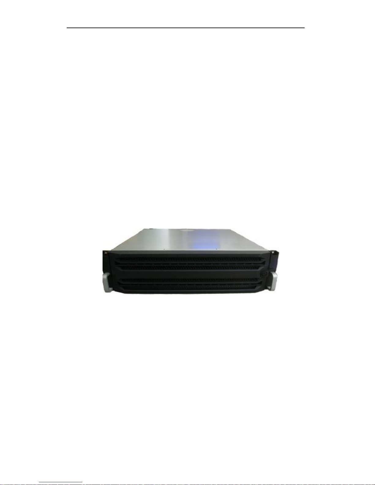
3.1.1 Front View
Figure 3. 1 Front View of Storage Chassis
3.1.2 Description of Front Panel
Note: After you open the front cover of the storage chassis with the supplied key, you can see the
front panel shown below. After you finish installing the storage chassis and hard disks, please close
the front cover with the supplied key.
Page 11
Quick Operation Guide of 81 Series Storage System
6
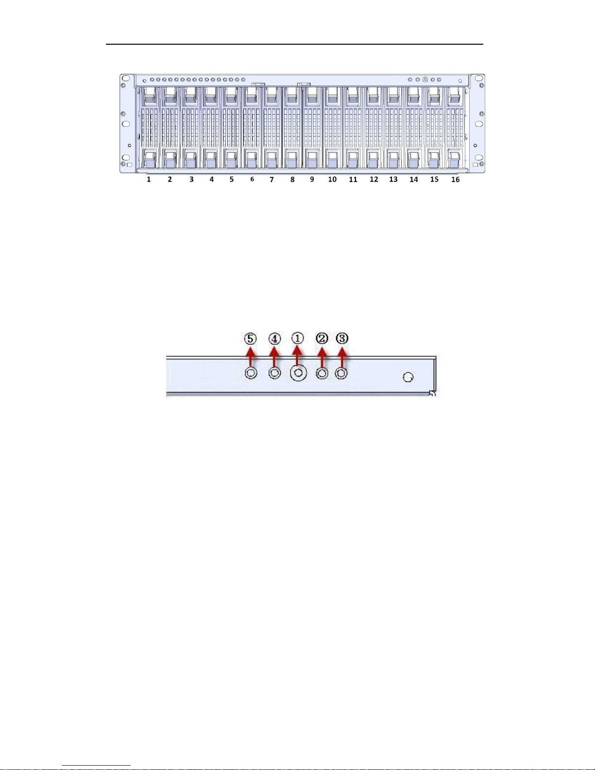
Figure 3. 2 Front View of Front Panel
1~16 indicates the sequence of the 16 hard disk slots.
3.1.3 Description of Buttons on Front Panel
The buttons on the front panel are shown below.
Figure 3. 3 Buttons on Front Panel
①: Power switch for turning on or off the system. To turn on the system, press this button; and to
turn off the system, press and hold the button for 4 seconds; and to force the system to close
when the system is abnormal, press and hold the button for 15 seconds.
②: System LED indicator for indicating the status of the system. When the system is in normal
status, the indicator is off. When the system is in abnormal status, the indicator lights in red.
③: Power LED indicator Indicates the power connection status. During the startup process, the
indicator flickers in green. After successful startup, the indicator lights in green.
④: Mute button for clearing the beep sound when the system exception occurs.
⑤: FN device positioning button. Press this button, the power LED indicator on the front panel and
I/O FN device positioning LED indicator on the rear panel flicker; press it again to stop the
indicators flickering. This button can help to position the specific storage chassis if you have
many devices.
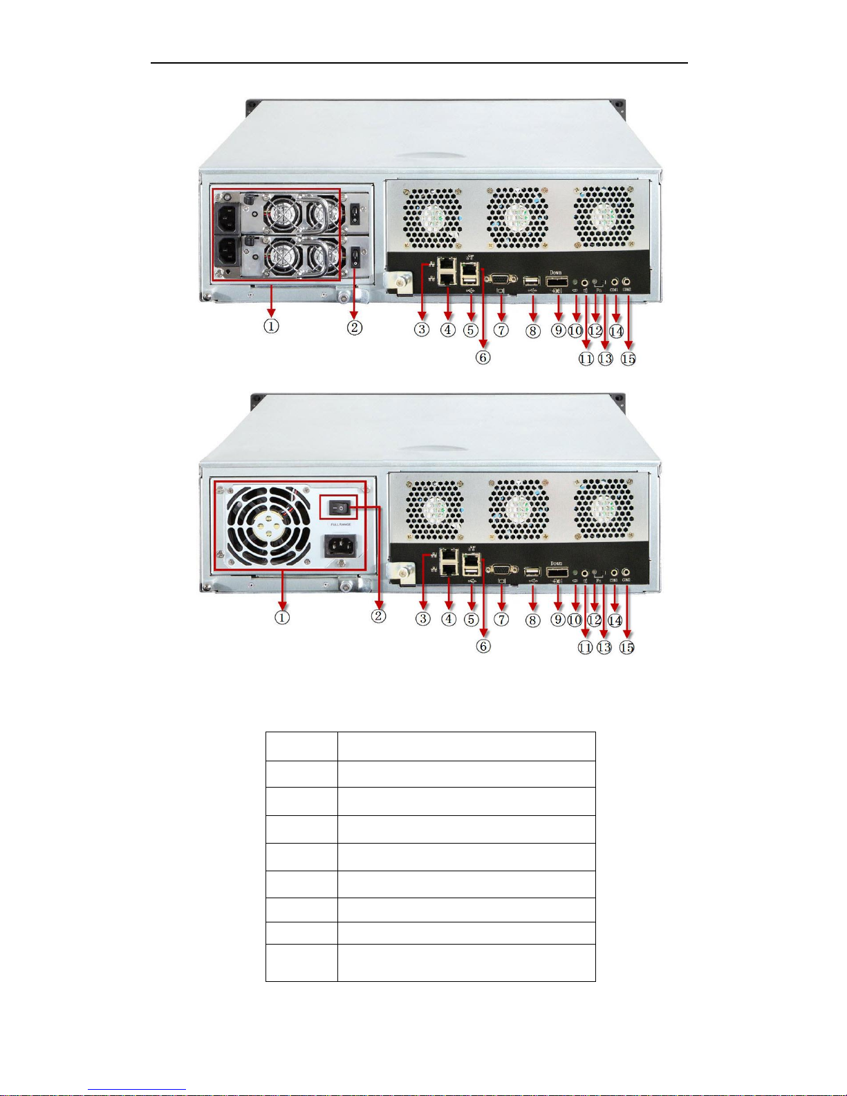
3.1.4 Description of Interfaces on Rear Panel
The rear panel of the system is shown below.
Page 12
Quick Operation Guide of 81 Series Storage System
7
Figure 3. 4 Rear Panel with Redundant Power Supplies
Figure 3. 5 Rear Panel with Single Power Supply
Table 3. 1 Description of Rear Panel
Icon
Description
①
Power supply
②
Power switch
③
NIC 2
④
NIC 1
⑤
USB port
⑥
Network management interface
⑦
VGA interface
⑧
USB port
Page 13

Quick Operation Guide of 81 Series Storage System
8
⑨
Expansion port
⑩
Expansion port LED indicator
⑪
Audio interface
⑫
I/O FN device positioning LED indicator
⑬
FN device positioning button
⑭
COM1 for connecting Hyper Terminal
⑮
COM2 for connecting mobile phone alarm device
or UPS (Uninterrupted Power Supply)
3.2 Installation Requirements
Before installation, please prepare the following equipment and accessories:
1. Network Storage System
2. Power cord
3. 100M/1000M network cable (CAT 5e recommended)
4. Quick Operation Guide
The following accessories are optional or user-provided:
1. Gigabit Ethernet switch (second-layer switch, user-provided)
2. Rack guide apparatus (optional)
Please check the following hardware connection
1. Network cable connection: use the network cable to connect the switch or router to the
network storage system. Please connect to LAN1 if only one network interface is to be used.
2. Power cord connection: connect the power cord to 110V~220VAC power supply.
3. 100M independent management port: by using a network cable to connect to the port, the
management PC or server is able to access the IP SAN/NAS system.
4. Serial port: connect the serial port to operate initialization for the storage system (optional).
Page 14
Quick Operation Guide of 81 Series Storage System
9
3.3 HDD Installation
3.3.1 Selecting HDD Model
It is recommended to adopt the certificated professional HDD models so as to ensure the stable
running of the system and the reliable data storage. It is highly recommended to purchase the
enterprise-class hard disks, e.g., Seagate Constellation™ ES, Western Digital WD RE3 and WD RE4
series hard disk. The use of non-enterprise hard disks for establishing RAID may cause instability of
the system running and thus lead to data damage. In case of hard disk failure, please replace it with
the functioning one immediately so as to prevent the data loss or performance effect.
Please refer to the List of Compatible HDD Models of our company for the recommended HDD
models.
Note:
In order to avoid damages during transportation, it is recommended to package and transport the
hard disks separately with the chassis of network storage system.
3.3.2 Installing HDD
To install the HDD on the bay brackets:
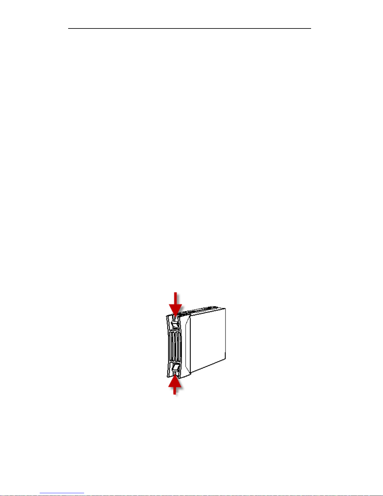
1. Press the spring lock of the HDD on the left, draw the handle and then pull out the HDD bracket
from the chassis along the guide apparatus.
Figure 3. 6 Pull out the HDD Bracket
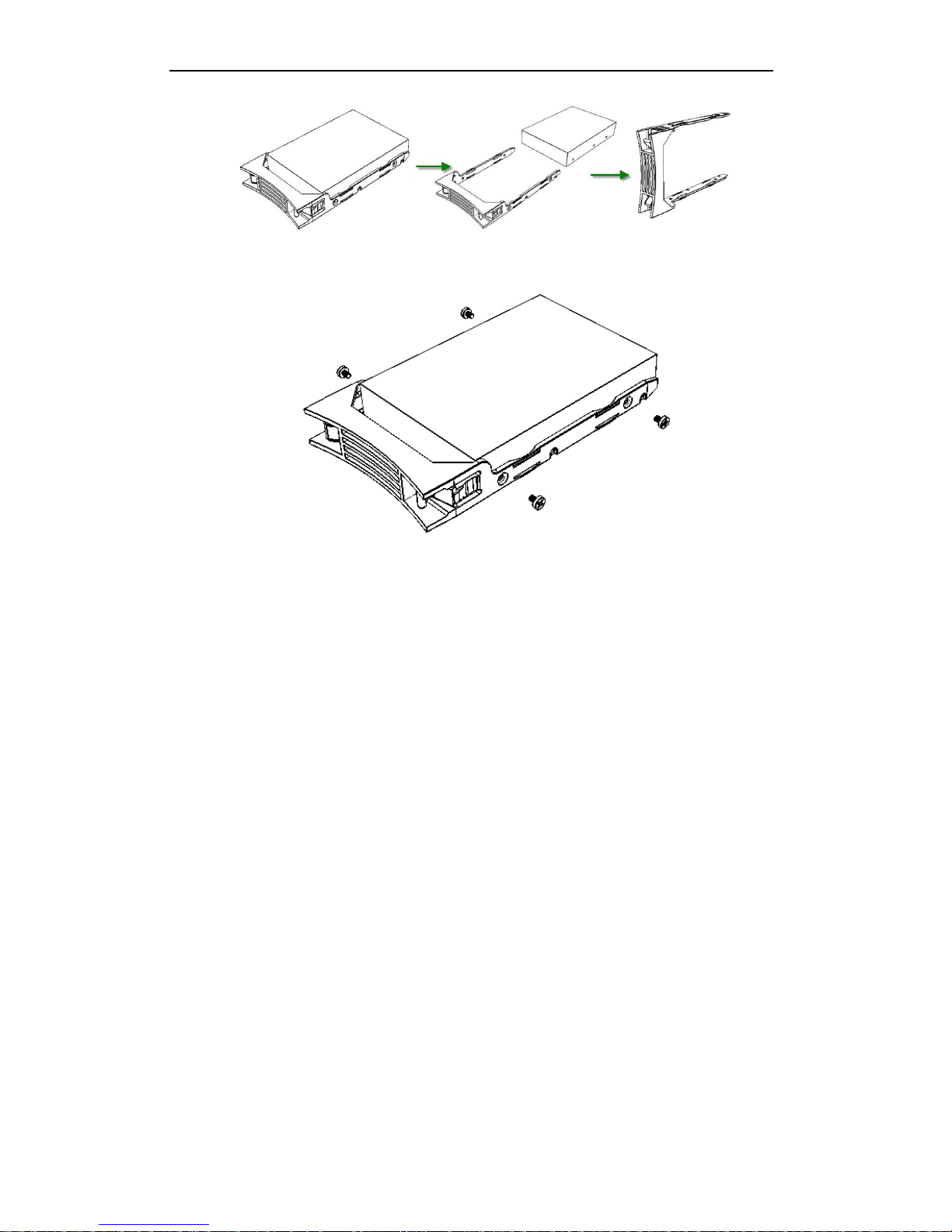
2. Remove the plastic parts from the HDD bracket.
Page 15
Quick Operation Guide of 81 Series Storage System
10
Figure 3. 7 Remove the Plastic Parts
3. Use four screws to secure the HDD (with the PCB side downward) to the bracket.
Figure 3. 8 Secure the HDD
4. Insert the HDD bracket (with the PCB side towards the left of the chassis) to the chassis and
push it along the guide apparatus to the bottom. Finally, press the securing handle to ensure
the bracket has been seated into position and lock it.
5. Repeat the operating steps above till all HDDs have been installed.
3.3.3 Precautions during HDD Installation
When you plug or unplug the hard disks, please take the following precautions:
1. After you have plugged the hard disk to its mounting bracket, please use the provided screws to
fix the four edges of the mounting bracket.
2. Make sure the HDD mounting bracket is steadily plugged to the chassis along the slot.
3. When you unplug the hard disk, unplug it about 3cm away from the chassis and then make it
stay about 30 seconds on the slot guide before totally unplug it from the chassis. Since the discs
of the hard disk are still spinning at high speed just after powering off, unplugging the hard disk
immediately will damage the discs.
4. The system supports disk hot swapping, yet the data storage safety is not ensured.
5. Please avoid frequent plugging/unplugging of the hard disks during the system running so as to
maintain long service life of the hard disks.
6. Take regular check and examine of the working status of the hard disks every two months, or
configure the system with auto check and examine task. Please refer to Chapter 4 for details.
Page 16
Quick Operation Guide of 81 Series Storage System
11
7. The certification for the new hard disk is required when it is plugged to the system for the first
time. Please refer to Chapter 7 for details.
Note:
Please avoid unplugging a hard disk when it is writing/reading data so as to prevent data loss.
3.4 Power On/Off
Apply power to the device and then press the power switch on front panel to start the system. The
system start-up will take about 3 minutes until it has produced “Di Di” sound.
If the unit fails to start up, please check whether all connections have been properly made.
As the unit has the power-off protection capability, the data will be automatically recovered when it
starts up again if the unit encounters power-off failure during its running.
When the system is started, it allows you to access the storage management center over WEB client
to view current status of the system.
Notes:
1. If the storage system is configured with redundant power supplies, please make all
connections of the power before starting the system.
2. The IP address of the PC or server for storage management must be set in the same network
with IP SAN/NAS system.
Power Off
Two methods can be used to power off the system:
1. It is recommended to turn off the system by clicking the button under the
in the Management System.
Note: You can also reboot the system in the Management System.
2. You can also press the POWER switch on front panel and the system will power off after a
while (not recommended).
Note: Do not hold the POWER switch to forcedly turn off the system to avoid damages to it.
Page 17
Quick Operation Guide of 81 Series Storage System
12
Chapter 4 IP Address Configuration for IP
SAN/NAS Access
4.1 Login
For the use of first time, the administrator is allowed to set the IP address for access to IP SAN/NAS.
The manage port and data NIC1/NIC2 network port provided by the system can be connected with
PC to configure system parameters over WEB Server.
Before you start
1. After having connected the management port, modify the IP address of PC connected to the
storage system in the same network (e.g., 10.254.254.10).
2. Use a crossover networking cable to connect the Ethernet port of your PC and the
management port of the storage system.
3. Make sure the network communication between the storage system and PC has been
successfully established.
Steps:
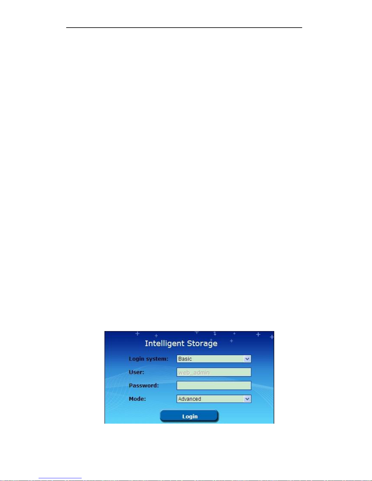
1. Input the IP address of system in the WEB browser, e.g., https://10.254.254.254:2004, for
access to the homepage of IP SAN/NAS management system.
2. Input the user name web_admin and the default password 123 to log in the management Web
page.
Figure 4. 1 Login
Page 18
Quick Operation Guide of 81 Series Storage System
13
3. Click System > Network to enter the network management page.
4. The administrator can also modify the IP address of the network port (100/100/1000Mbps).
The default IP address of the network port is 192.168.0.100.
4.2 Configuring Network Parameters
4.2.1 Modifying Network Parameters for Data NIC1/NIC2
Steps:
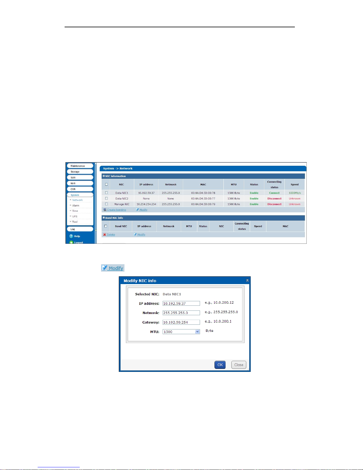
1. Click System > Network to enter the network management page.
Figure 4. 2 Network Management Interface
2. On the Bond NIC info field, check the checkbox to select the NIC port to modify.
3. Click the button to enter the following interface:
Figure 4. 3 Modify Bond NIC Info
4. You can modify the IP address, Netmask, Gateway and MTU value in the Modify bond NIC info
interface.
Note: When the MTU value is set to higher than 1500, it will effectively improve the network
Page 19
Quick Operation Guide of 81 Series Storage System
14
transmission performance, yet it must be supported by the used router and other network
devices.
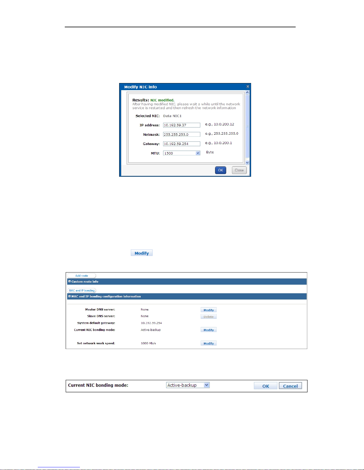
5. Click OK to save the settings. When the modification is successful, the following interface pops
up:
Figure 4. 4 Successfully Modified Bond NIC Info
4.2.2 Configuring Bonding Mode
Steps:
1. Click System > Network to enter the network management page.
2. In the MAC and IP bonding configuration information field, the current NIC bonding mode can
be viewed. Click the button of the Current NIC bonding mode, and a drop-down
menu for mode selection is available.
Figure 4. 5 Current NIC Bonding Mode
3. Select the bonding mode from the drop-down menu and then click OK to save the settings.
Figure 4. 6 Modify NIC Bonding Mode
Note: Please restart the system after the NIC bonding mode is modified to activate the new settings.
Page 20

Quick Operation Guide of 81 Series Storage System
15
4.2.3 Configuring Multi-NIC Bonding
Steps:
1. On the Network Management interface, click the button in the NIC
information field to enter the pop-up dialog box.
2. Click OK to confirm the creation of NIC bonding. And the message box indicating successful
creation will pop up in few seconds.
Note: Please stop accessing to the storage system when you are operating the bonding
configuration.
4.2.4 Deleting Multi-NIC Bonding
Steps:
1. On the Network Management interface, select the bond NIC from the list in the Bond NIC info
field to be deleted.
2. Cick the button to enter the pop-up dialog box.
3. Click OK to confirm the deletion of bonding. And the message box indicating successful
deletion will pop up in few seconds.
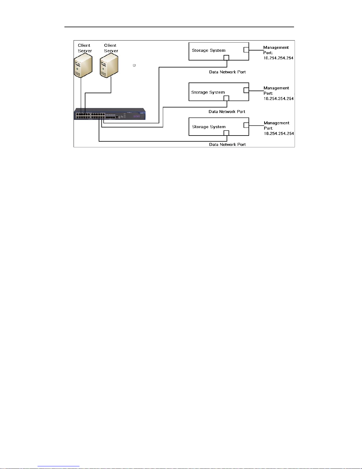
4.2.5 Network Connection
Please obey the following 4 principles to connect the storage system and the client server (your PC,
laptop or server) to the network.
1. In order to guarantee the stability of the network condition, it is strongly recommended to
configure the IP address of the storage system and the IP address of the client server in the
same network segment.
2. The client server and the storage system must connect to the switch directly.
3. All the data network ports must connect to the switch.
4. The IP address 10.254.254.254 of the management port is used for debugging the storage
system and cannot be used for video streaming.
Note: You can use both the management port and the data network ports for debugging the storage
system.
Page 21
Quick Operation Guide of 81 Series Storage System
16
Figure 4. 7 Network Connection
Page 22
Quick Operation Guide of 81 Series Storage System
17
Chapter 5 System Monitoring and Alarm
5.1 System Monitoring
After logging in the storage system, the administrator can view the basic status and the running
information of the system. The top-right corner of the web page shows the current status of the
system. If the storage system is running normally, the status shows as follows.
Figure 5. 1 Normal System
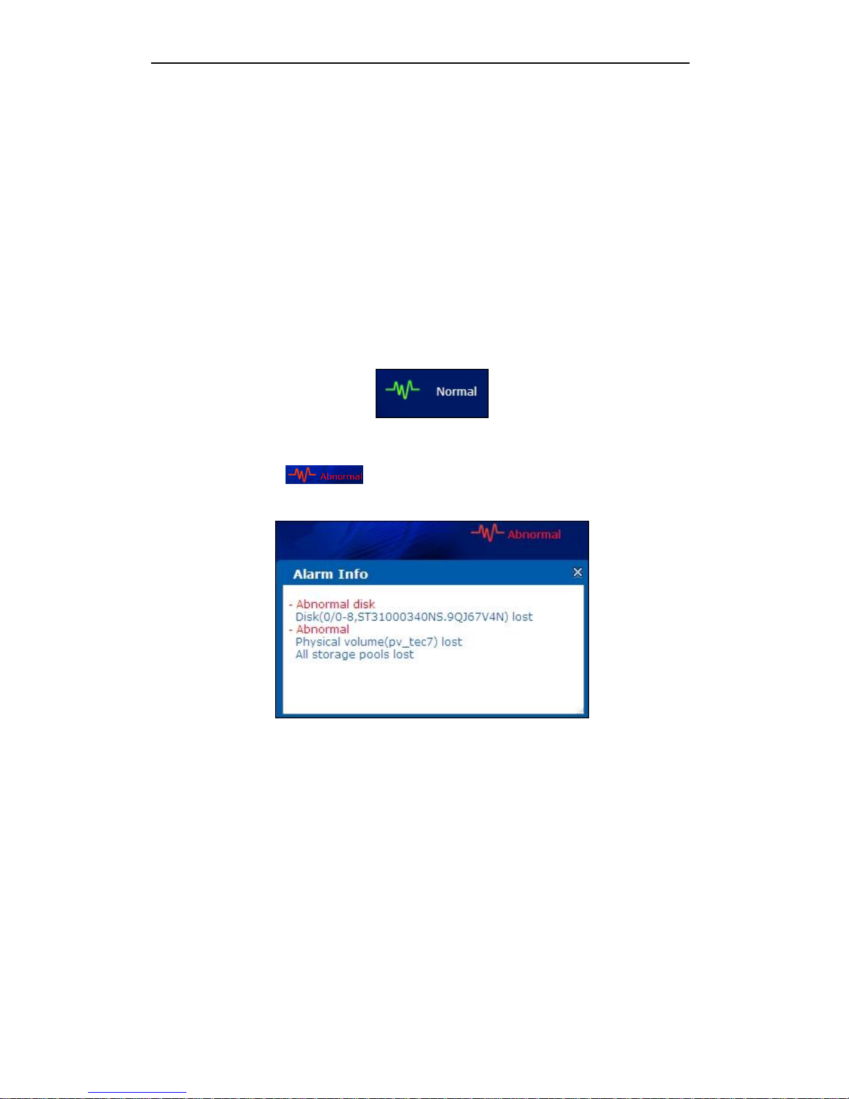
When the system is exceptional, you can see the abnormal information listed in the top-right corner
of the web page. Click to unfold the alarm message box and you can see abnormal
information of the system.
Figure 5. 2 Abnormal System
The alarm information of the system includes but is not limited to the following conditions:
1. Hard Disk: The status and connecting condition of the disks installed on the chassis or
expandable cabinet.
2. Environmental Control Information: The temperature, fan and power supply of the chassis or
expandable cabinet.
3. System Business Status: iSCSI, NAS and CVR.
4. Network: The connecting status of the data network port or management port.
Page 23

Quick Operation Guide of 81 Series Storage System
18
5.2 Environmental Information
In the Environmental Information interface (Maintenance>Control Message), the controller
information, the chassis information, the expandable cabinet information and the audio warning
information are listed.
Controller Information
The information of chassis fan speed, chassis temperature, fan control panel and power supply will
be monitored. When the fan is abnormal (e.g., low speed) or the temperature is abnormal (e.g., high
temperature), the system shows the corresponding alarm messages.
Expandable Cabinet Information
It shows the manufacturer, type, bay number, version, fan speed, temperature and other
information of the expandable cabinet.
Fan Speed Control
The fan of the chassis can set the speed according to the ambient temperatures to adjust the
internal working temperature of the chassis. Low temperature can help to extend the system life
and reduce the failure rate, but also increase the noise and power consumption. Our storage system
provides 3 working modes of the fan, including high speed, medium speed (default) and low speed.
In the same circumstance, comparing to medium speed, the high speed can decrease the
temperature and the low speed can reduce the noise.
Audio Warning
The system makes the audible warning when the system is in abnormal status. You can click the
to stop the audible warning. When a new exception occurs, the system will make audible
warning again.
Page 24

Quick Operation Guide of 81 Series Storage System
19
Chapter 6 Creation and Use of RAID
The system supports RAID service which provides redundant storage for the data on disks. When the
RAID is set to RAID 5, it will ensure data safety in case of one disk failure in this RAID group.
Before providing the network storage service by single physical disk or RAID group, you should add a
single physical hard disk or RAID group to a virtual storage pool to form a physical volume by means
of virtualization management technology, and then create several LUNs (logical unit number) on the
physical volume to create NAS, CVR or iSCSI disks.
6.1 Logging in Storage Management System
Steps:
1. Input the IP address of system in the WEB browser, e.g., https: //10.254.254.254:2004, for
access to the homepage of IP SAN/NAS management system.
Figure 6. 1 Login
2. Select the Login system to Basic, input the user name web_admin and the default password
123, and then select the Mode to Advanced to login the Web page of management system.
3. Click Storage on the left navigation bar to enter the storage management page.
Page 25

Quick Operation Guide of 81 Series Storage System
20
Figure 6. 2 Storage Management Interface
6.2 Disk Management
6.2.1 Viewing Disk List
Click Storage> Disk to enter the disk management interface.
Note: If there are no hard disks installed in the storage system, no disk information is available.
Figure 6. 3 Disk Management Interface
The available hard disks can be viewed on the interface, including the detailed disk information. You
can click the button to rescan the disks available in the system.
Click the button to view the state of all hard disks in the list, or click to
view the detailed state of the selected disk.
Figure 6. 4 Disk State
Page 26

Quick Operation Guide of 81 Series Storage System
21
Figure 6. 5 Specific Disk State
6.2.2 Viewing Disk Checking Status
On the Disk Management interface, select the disk(s) from the list and click to enter
the following interface:
Figure 6. 6 Check Status of Disk
Three types of check status shown: checking, unsubmitted and waiting.
Unsubmitted: the current disk has not been submitted for checking.
Waiting: the disk is waiting in the queue to be checked.
Checking: the current disk is under checking.
6.2.3 Checking Disk
When a physical disk is used in the storage system for the first time, the disk status will be shown as
Unauthorized. You should check the disk before use.
Figure 6. 7 Check Disk
Page 27

Quick Operation Guide of 81 Series Storage System
22
Steps:
1. Select the disk(s) from the list to be checked.
2. Click to enter the disk check interface:
Figure 6. 8 Set Disk Check
3. Select the Check style to Quick Check or Full Check.
Quick Check: check all disks simutanously and take short time.
Full Check: check disks one by one in detailed which may take a long time. It is recommended
to adopt this mode when the disks are used for the first time.
4. Click to start checking the selected disk(s).
Figure 6. 9 Check Disk
5. After the disk(s) have finshed checking, you can view the disk status in the disk management
interface.
Page 28

Quick Operation Guide of 81 Series Storage System
23
6.3 Array Management
6.3.1 Creating an Array
Steps:
1. Click Storage > Array to enter the array management interface.
Figure 6. 10 Array Management Interface
2. Click the button to enter the create array interface:
Figure 6. 11 Create Array Interface
3. Edit the array name. Only the letters and numerals are allowed.
4. Set the RAID level from the drop-down list. The RAID 5 is recommended.
5. Select the block size (default: 64KB) and the I/O priority.
Block Size: The basic unit of the RAID data. When the large volume of input/output
Page 29

Quick Operation Guide of 81 Series Storage System
24
business data is required, choose the larger block size; when the small volume of
input/output business data is required, choose the smaller block size. The default size is 64KB
and it is the most balanced option at present.
I/O Priority: Set the priority for the RAID I/O (Input / Output data) and the business I/O.
And four options are available.
Intelligent (default): When the business I/O is small, the RAID I/O will be increased
automatically; when the business I/O increases, the RAID I/O will be decreased automatically.
Balance: Balance the business I/O and the RAID I/O to guarantee 3MB/s minimum speed for
the RAID I/O. This option is usually used when the business I/O is large and the array
rebuilding or array initialization needs to be ensured.
Performance Priority: The RAID I/O will be stopped as long as business I/O is processed. This
option is commonly used for business test with high performance requirement.
Protection Priority: Keep the RAID I/O as a priority and the business I/O will be affected. This
option is mainly used to complete the array rebuilding or array initialization as soon as
possible when there is no business I/O.
6. Select the physical disks from the list for creating the array.
7. Click the OK button, and the following dialog box pops up:
Figure 6. 12 Pop-up Dialog Box
8. Click Close to finish the settings. And the created array will be displayed on the list on the array
management interface.
Figure 6. 13 Successfully Added Array
Notes:
1. Only the enterprise disks are allowed for creating the array.
2. At least 3 physical disks must be selected for creating RAID 5.
3. While creating RAID, it is recommended to select the physical disks with the same model and
capacity to maintain better performance of RAID.
Page 30

Quick Operation Guide of 81 Series Storage System
25
6.3.2 Rebuilding an Array
The array rebuilding function is used for rescuing the data from the unstable or failure physical disk
existed in the array, aiming to protect data and recover the completeness of the array.
The operation is valid when there is physical disk available in the array which has the same capacity
with the failure disk.
Rebuilding a Hot Spare Disk
The hot spare disk is used to automatically replace the disconnected or failure disk in the array so as
to ensure the data security. It is recommended to add the hot spare disk during the configuration of
RAID.
Two hot spare modes are configurable: Global and Local.
Global Hot Spare
Steps:
1. On the array management interface, click the button to enter the adding
hot spare interface:
Figure 6. 14 Add Global Hot Spare
2. Select the Group from the drop-down menu to Global.
3. Select the available disk to be used as hot spare disk.
4. Click the OK button, and the following dialog box pops up:
Page 31

Quick Operation Guide of 81 Series Storage System
26
Figure 6. 15 Pop-up Dialog Box
5. Click OK to finish the adding of hot spare disk.
You can view the information of the successfully added hot spare on the Hot Spare interface:
Figure 6. 16 Successfully Added Hot Spare
When there is a disk disconnected or failed, the array status will change to Degraded. With the
global hot spare disk configured, the system will automatically start to rebuild the array and the
array status will show the rebuilding speed and remaining time.
Figure 6. 17 Array Status
Local Hot Spare
Steps:
(1) Click the button to enter the adding hot spare interface.
Figure 6. 18 Add Local Hot Spare Disk
Page 32

Quick Operation Guide of 81 Series Storage System
27
(2) Select the Group to Local.
(3) Select the array to which the hot spare is added.
(4) Select the available disk to be used as hot spare disk.
(5) Click OK to finish the adding of hot spare disk.
You can view the information of the successfully added local hot spare on the Hot Spare
interface:
Figure 6. 19 Successfully Added Hot Spare
When the specified array status changes to Degraded, the system will automatically start to rebuild
the array.
Auto-rebuilding
Steps:
1. Click Storage > Settings to enter the device settings interface:
Figure 6. 20 Enable Auto-rebuild
2. Enable the Auto-rebuild function.
3. When the array is degraded due to disk disconnection or failure, you can insert a new disk to
the system which is used for array rebuilding, and the system will start to rebuild the array.
Manual-rebuilding
When there is an idle disk available in the system, and the Auto-rebuild function is disabled and no
hot spare disk is available, you need to start the array rebuilding manually.
Steps:
1. Enter the array information interface.
Figure 6. 21 Array Information List
Page 33

Quick Operation Guide of 81 Series Storage System
28
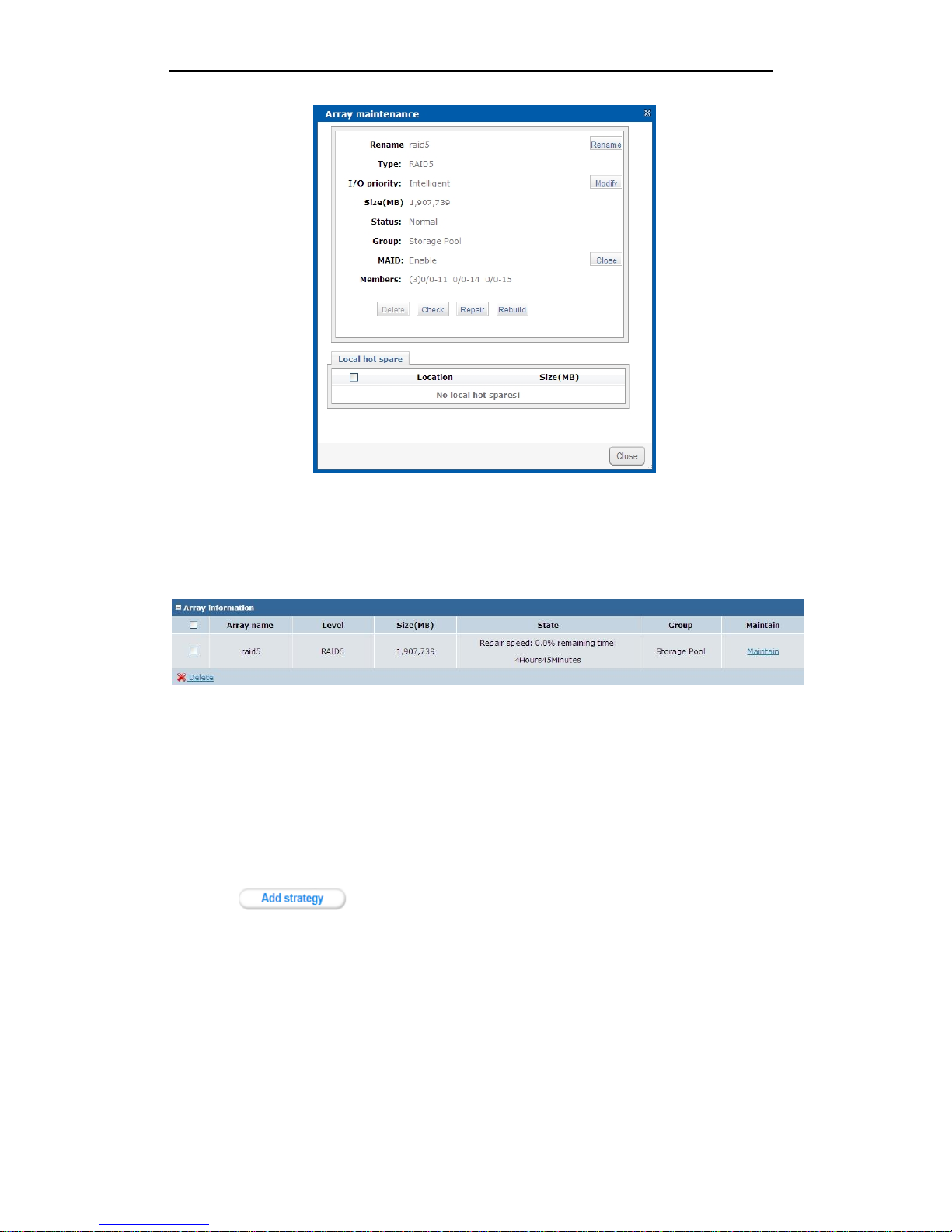
2. If the array is Degraded, click Maintain on the array information list to enter the array
maintenance interface.
Figure 6. 22 Array Maintenance Interface
3. Click the Rebuild button.
4. Select the available disk and click the OK button to start the array rebuilding.
Force-rebuilding (Optional)
Steps:
1. Click Storage > Settings to enter the device settings interface:
Figure 6. 23 Enable Force-rebuild
2. Enable the Force-rebuild function.
3. After the force-rebuild is enabled and in case that there is I/O error of non-rebuilt disk
occurring during the process of array rebuilding, the system can still ensure the array to
continue the rebuilding. And the corresponding message can be viewed on the operating log of
Page 34

Quick Operation Guide of 81 Series Storage System
29
the system reminding you to replace this non-rebuilt disk after the array rebuilding is complete
so as to avoid data loss and enhance the data security.
6.3.3 Verifying Array
The array inspection is used to prevent the data error and file loss in the process of data storage,
aiming to maintain the effectiveness and completeness of the data. You should take a regular check
and maintenance for the disk array to avoid data invalidation, reduce the error rate of data
writing/reading and thus ensure the stability of the system running and integrity of the database.
Inspecting Array Manually
Steps:
1. Click Storage>Array to enter the array management interface.
2. When the array state is Normal, click Maintain to enter the array maintenance interface:
Figure 6. 24 Inspect Array by Manually
3. Click the Inspect button to start inspecting the selected array.
Inspecting Array by Strategy
When the array is created, the system will automatically add a strategy which starts inspecting the
array 3 months later and with a duration of 3 months.
You can also add a strategy manually of verifying the array.
Page 35

Quick Operation Guide of 81 Series Storage System
30
Steps:
1. When the array status is Normal, click Maintenance>Common to enter the maintenance
interface.
2. Click to enter the following interface:
Figure 6. 25 Add Strategy
3. Select the type to RAID verification from the drop-down list and the verify mode to Check.
4. Select the array to verify.
5. Edit the name of the strategy, set the cycle time and the start time/end time.
6. Click OK to confirm the settings.
7. You can view the successfully added strategy in the list of RAID verify strategy information.
Figure 6. 26 Successfully Added Strategy
6.3.4 Repairing Array
Repairing Array by Manually
Steps:
1. Click Storage > Array to enter the array management interface.
2. When the array status is Normal, click Maintain to enter the array maintenance interface:
Page 36
Quick Operation Guide of 81 Series Storage System
31
Figure 6. 27 Repair Array
3. Click the Repair button to start repairing the selected array.
4. When the array is repairing, you can view the status information in the array information list,
including the repairing speed and remaining time.
Figure 6. 28 View Repairing Status
Repairing Array by Strategy
Steps:
1. When the array status is Normal, click Maintenance>Common to enter the maintenance
interface.
2. Click to enter the following interface:
Page 37

Quick Operation Guide of 81 Series Storage System
32
Figure 6. 29 Add Strategy
3. Select the type to RAID verification from the drop-down list and the verify mode to Repair.
4. Select the array to repair.
5. Edit the name of the strategy, set the cycle time and the start time/end time.
6. Click OK to confirm the settings.
7. You can view the successfully added strategy in the list of RAID verify strategy information.
Figure 6. 30 Successfully Added Strategy
6.4 Virtual Storage Pool Management
The Virtual Storage Pool makes a list of physcial volumes to manage multiple physical disks or RAID
groups. A physical volume can be divided into logic volumes for providing different data storage
service.
Steps:
1. Click Storage>Storage Pool to enter the storage pool management interface.
Page 38

Quick Operation Guide of 81 Series Storage System
33
Figure 6. 31 Storage Pool Management
2. Click the button to enter the following interface:
Figure 6. 32 Add Storage Pool
3. Select the array to be added with virtual storage pool by checking the checkbox.
4. Edit the physical volume name.
5. Click OK to add the storage pool.
6. You can view the successfully added storage pool in the list of physical volume information.
Figure 6. 33 Successfully Added Storage Pool
Page 39

Quick Operation Guide of 81 Series Storage System
34
Now, the physical volume of array r5 is available in the system. You can partition the volume
space and create some LUNs to be assigned to NAS, iSCSI, CVR and other storage service. The
storage space should be effectively used by defining the capacity on demand.
Page 40

Quick Operation Guide of 81 Series Storage System
35
Chapter 7 Bad Disk Management
Purpose:
The possibility for hard disk failure increases with its working time. That is the significant reason why
we set the working mode of HDD as RAID. Although the storage system will still keep running in case
of a single hard disk failure in RAID 5 working mode, it has been in an unstable status. You must take
some measures, such as replace the bad disk(s), to avoid reduced performance and data loss.
7.1 Configuring Alarm for Bad Disks
Steps:
1. Enter the Disk Management interface.
Storage>Disk
Figure 7. 1 Disk Information
2. If the disk is abnormal, the system will automatically detect the disk. After the detection, the
alarm window will show the alarm information, with the disk No. and model.
Figure 7. 2 Alarm Information
Page 41

Quick Operation Guide of 81 Series Storage System
36
7.2 Replacing the Bad Disks
Steps:
1. Before replacing the bad disk(s), you need to check the new disks.
2. If you want to check all the disks, click on the navigation bar
to list all the disks.
3. Select all the disks by checking checkbox of the disks, and click to starting disk
detection. You can also check checkbox of part of the disks to check the selected disks. For
detailed information about disks detection, refer to Chapter 6.2.3.
Note: The navigation bar will show when more than 10 disks are
installed in the device.
Figure 7. 3 Disk Information
4. After the new disks are checked as normal, replace the bad disk with the new disk and insert
the HDD bracket into the same slot. You can send the replaced bad disk to disk manufacturer or
the engineer of our company for detecting. It is not recommended to reuse the replaced disk,
in case the bad disk may cause RAID instability or data loss.
5. Rebuild the array after replacing the bad disk. Refer to Chapter 6.3.2 for more information
about rebuilding the array.
Page 42

Quick Operation Guide of 81 Series Storage System
37
Chapter 8 Configuring iSCSI Settings
Purpose:
The iSCSI connection of IP SAN/NAS system is capable of mapping the storage space to the local
client server so as to achieve local management and operation.
Before you start:
Please insert the hard disks into the device, initialize the disks and create storage pool properly.
Note: For information about configuring array and virtual disks, refer to Chapter 6.3 & Chapter 6.4.
8.1 Creating iSCSI Volume
Steps:
1. Enter the LUN Management interface.
Storage>LUN
Figure 8. 1 LUN Management Interface
2. Click to create LUN. Enter the LUN name, LUN size and block size in the
corresponding text field.
3. Check checkbox to select a physical volume in which the LUN is located.
Page 43

Quick Operation Guide of 81 Series Storage System
38
Figure 8. 2 Create a LUN
8.2 Enabling iSCSI Service
Steps:
1. Enter the iSCSI Management interface.
SAN>iSCSI
Figure 8. 3 iSCSI Management Interface
2. Click to enable the iSCSI service. Enter the Client IP and iSCSI ID; select the
Chap authentication and Access mode; choose a LUN to enable iSCSI service.
Note: If you enter the specific IP address for Client IP, then only the client server with that IP
can connect the iSCSI. If multiple servers need to access the iSCSI service, you can enter 0.0.0.0.
Page 44

Quick Operation Guide of 81 Series Storage System
39
Figure 8. 4 Enable iSCSI
3. Click to confirm enabling the iSCSI service.
8.3 Creating iSCSI Connection in Windows 2008
Use the iSCSI Initiator software in Windows 2008 to configure and establish the iSCSI connection to
the storage system.
Note: In Windows XP or Windows 2003, you need to click to enter the Help interface and
download the corresponding software and install it on your PC. If the downloaded software cannot
be installed properly, or the latest software is needed, you can log on to the Microsoft official
website to download the corresponding software and install it.
Figure 8. 5 Download iSCSI Initiator Software
Task 1: Connecting iSCSI Service
Steps:
1. Enter the Start menu, and select iSCSI Initiator to enter the following interface.
For 64-bit PC
For 32-bit PC
Page 45

Quick Operation Guide of 81 Series Storage System
40
Figure 8. 6 Initiator Software Interface
2. Click tab and click . The Add Target Portal dialog box will pop up.
Figure 8. 7 iSCSI Initiator Properties
Page 46

Quick Operation Guide of 81 Series Storage System
41
Figure 8. 8 Add Target Portal
3. Enter the IP address and port of the storage system, and click to confirm the settings.
Click tab to enter the following interface.
Note: Inactive indicates that the storage target is discovered but not connected. You can
connect multiple storage targets. You can refer to the following steps to configure the
connection of iSCSI service
Figure 8. 9 Targets
4. Click and the Log On to Target dialog box will pop up. If you check
checkbox, the iSCSI storage system will be
automatically connected when the PC starts next time. Click to complete the
connection.
Page 47

Quick Operation Guide of 81 Series Storage System
42
Figure 8. 10 Log On to Target
5. After connecting the storage system successfully, the status of the storage target will change to
Connected.
Figure 8. 11 iSCSI Connected
Task 2: Disconnecting iSCSI Service
Steps:
1. Select the storage target and click .
2. In the pop-up Target Properties interface, check checkbox for the Identifier and click
to disconnect the connection.
3. Click to confirm the settings.
Page 48

Quick Operation Guide of 81 Series Storage System
43
Figure 8. 12 Disconnect Storage Target
8.4 Mapping to Local Disk & Formatting iSCSI Disk
After iSCSI connection, the storage system can be considered as a local disk.
Steps:
1. Enter the Start menu, and select Administrative Tools > Computer Management > Storage >
Disk Management. The Initialize Disk guide will pop up.
Figure 8. 13 Initialize Disk Guide
2. Check checkbox to select disk(s) and click to confirm initializing the disk(s).
Page 49

Quick Operation Guide of 81 Series Storage System
44
Figure 8. 14 Disk Management
3. You can map the storage system to a basic disk or a dynamic disk. The basic disk is accessible
when the device is started, and the dynamic disk processes more features than the basic disk,
e.g., extended dynamic volume and multiple disk volumes.
4. Right-click an iSCSI disk and select New Simple Volume to start activating the disk. Follow the
pop-up guide to map the disk to local storage.
5. After formatting successfully, you can access the disk(s) in Computer.
8.5 Creating iSCSI Connection in Redhat5
The following content is the introduction of creating iSCSI connection in Redhat5.
Steps:
1. Discover the target.
# iscsiadm -m discovery -t sendtargets -p 10.192.52.166
10.192.52.166:3260, 1 iqn.2004-05.storos.t-111
2. Log on the target.
# iscsiadm -m node -T iqn.2004-05.storos.t-111 -p 10.192.52.166:3260 -l
Login session [iface: default, target: iqn.2004-05.storos.t-111, portal: 10.192.52.166, 3260]
3. View the disk information.
Page 50
Quick Operation Guide of 81 Series Storage System
45
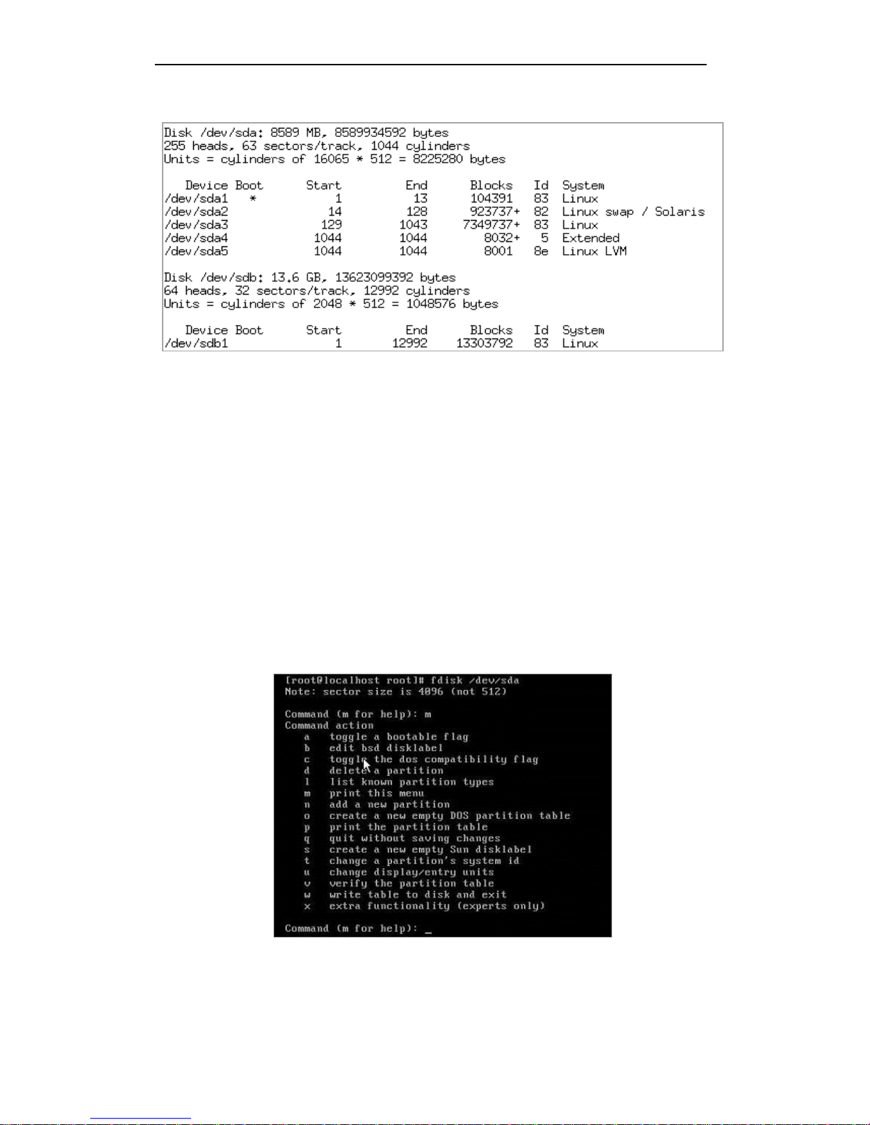
# fdisk -l
Figure 8. 15 Disk Information
4. Use the fdisk command for disk partitioning.
fdisk [-l] [-b SSZ] [-u] device
-l: View the status of partition table of the device.
-b SSZ: Display the partition size on the standard output.
-u: Used with -l, replace the cylinder number with partition number to indicate the start
address of each partition.
device: The name of the device.
Note: The fdisk command is the most common partition tool and is defined as the Expert
partition tool. A second-level menu is included in the fdisk command.
5. Enter the command: # fdisk /dev/sdb. And the command prompts will come out: Command (m
for help).
Figure 8. 16 fdisk Command for Partitioning
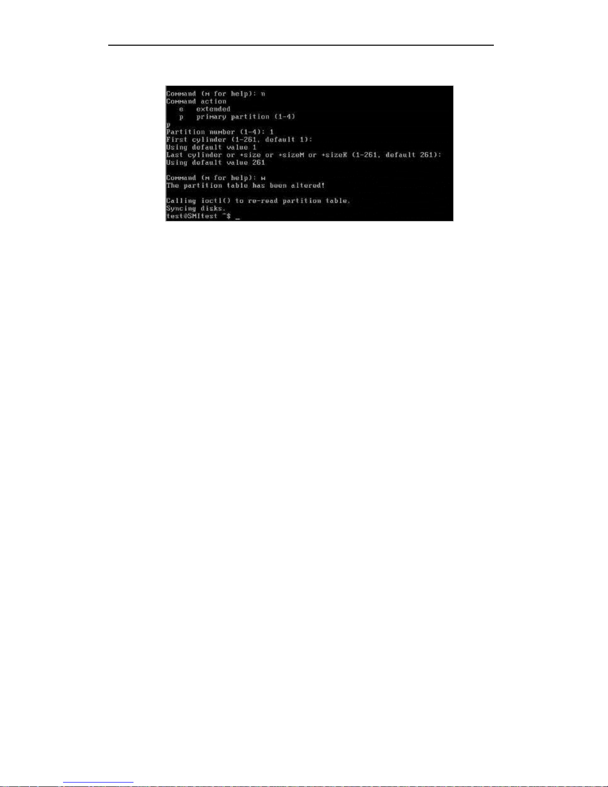
6. Enter n to create a partition and the prompt for selecting primary partition or extended
partition will come out. We often use the primary partition. And then enter the partition
Page 51
Quick Operation Guide of 81 Series Storage System
46
number, first cylinder and partition size. Enter w to write the disk information.
Figure 8. 17 Partition Disk
7. Format the partition.
# mkfs.ext3 -b 4096 /dev/sdb1
8. Set the mount point.
# mkdir /mnt/scsi01
# mount /dev/sdb1 /mnt/scsi01
Now the Linux server has connected the iSCSI disk and you can do the same operation as the
local SCSI disk of the Linux server.
9. Mount an iSCSI disk automatically.
Modify /etc/rc.local through the vi editor. Use the command Shift + G to locate the cursor at
the last line. Use the command o and then enter #mount /dev/sd1 /mnt/scsi01. After
saving the file and rebooting the Linux server, the server can mount the iSCSI disk
automatically.
8.6 Creating iSCSI Connection in Suse 10
This section introduces the procedure iSCSI connection in Suse 10.
Steps:
1. Discover the target.
# iscsiadm -m discovery -t sendtargets -p 10.192.52.166
[1b72d5] 10.192.52.166:3260,1 iqn.2004-05.storos.t-123
2. Log on the target.
# iscsiadm -m node -r 1b72d5 -l
3. View the disk information.
# fdisk –l
Page 52

Quick Operation Guide of 81 Series Storage System
47
Figure 8. 18 Disk Information
4. Use the fdisk command for disk partitioning, and then format the disk.
# fdisk /dev/sdb
# mkfs.ext3 -b 4096 /dev/sdb1
5. Set the mount point.
# mkdir /mnt/scsi01
# mount /dev/sdb1 /mnt/scsi01
Now the server has connected the iSCSI disk and you can do the same operation as the local SCSI
disk of the Linux server.
Page 53

Quick Operation Guide of 81 Series Storage System
48
Chapter 9 Configuring NAS Settings
The NAS space can be used as the network shared disk within the office network to realize the share
of data, software tools and other materials.
9.1 Creating NAS Net Disk
Before you start:
Please create the virtual storage pool before configuring the following settings. Refer to the Chapter
6.4 for detailed information.
9.1.1 Creating NAS Volume
Steps:
1. Enter the LUN Management interface.
Storage > LUN
2. Click and enter the LUN name, LUN size and block size (512 byte by default) in
the corresponding text field of the pop-up dialog box. Check checkbox to select a physical
volume in which the LUN is located.
Figure 9. 1 Create a LUN
3. Enter the NAS Disk Management interface.
NAS>NAS Disk
Page 54

Quick Operation Guide of 81 Series Storage System
49
Figure 9. 2 NAS Disk Management Interface
4. Click and select the available LUN in the LUN name dropdown list. Click
to creating the NAS volume.
Figure 9. 3 Create NAS Volume
9.1.2 Setting NAS Configuration
Steps:
1. Enter the NAS Configuration interface.
NAS>NAS Config
Figure 9. 4 NAS Configuration
2. You can configure the Server name, NetBIOS name and Workgroup to fit the office
environment.
3. For user authentication mode, you can select Local, Share or ADS.
Local: This mode adopts the local user management system of the storage device, and the user
name and password are saved in the storage server.
Page 55

Quick Operation Guide of 81 Series Storage System
50
Share: It allows any user to log in the system without need of user name authentication.
ADS: This mode is based on the domain, and all users adopt the Active Directory for
authentication. The ADS mode is optional.
9.1.3 Adding NAS User
Note: If you set the user authentication mode as Local, you need to create the NAS user before
creating NAS disk.
Steps:
1. Enter the NAS User Management interface.
NAS>Users (Groups)
Figure 9. 5 NAS User Management
2. Click and set the name, password, group, quota and NAS settings of the NAS
user.
Primary group: Default and the defined group(s) can be selected.
Group: Select the group for the user. The settings of the group define the permission of user,
like quota and read-write permission of the user.
Quota: Set quota for user.
If you do not configure the capacity for the user and the user is in the default primary group,
it is 0 by default which means the user can use total capacity of the NAS volume.
Example: if the capacity of the NAS volume is 20G, the user is in the default primary group
and you do not configure the capacity for the user or you set it as 0, then the usable disk
capacity for the user is 20G.
If the user locates in a primary group of which the quota is not 0, and you have configured a
quota for the user, then the usable disk capacity for the user is the smaller one.
Example: if the capacity of the NAS volume is 20G and the quota configured for the user of
NAS disk is 0, and the quota of the primary group in which the user locates is 600M, then
the usable disk capacity for the user is 600M.
NAS settings: Set the protocol for file service and configure the NAS disk permission for the
Page 56

Quick Operation Guide of 81 Series Storage System
51
user.
Figure 9. 6 Add a NAS User
3. Click to create a new user.
9.1.4 Creating NAS Disk
Steps:
1. Enter the NAS Disk Management interface.
NAS>NAS Disk
Figure 9. 7 NAS Disk Management
2. Click and select the available NAS volume, enter the name for NAS disk and set
the protocol for the disk.
Page 57

Quick Operation Guide of 81 Series Storage System
52
Figure 9. 8 Add a NAS Disk
3. Select the protocol and configure the corresponding settings. Set the read/write access for the
user that adopts the protocol.
Note: If the user authentication mode (Chapter 8.1.2) is set as Share and the protocol is
selected as Windows (CIFS), it only needs to select the access mode to read-write or read-only.
The user name is not required.
Figure 9. 9 Protocol Settings
Page 58

Quick Operation Guide of 81 Series Storage System
53
9.2 Creating NAS Disk Connection
Steps:
1. Right-click Computer or Network on the desktop of your PC and select Map Network Drive.
The guide for Map Network Drive will pop up.
Note: If you want to disconnect the shared space, you can select Disconnect Network Drive.
Figure 9. 10 Right-click Menu
Figure 9. 11 Map Network Drive Guide
2. Select the letter for the network drive and enter the IP address and NAS disk name in the
Folder text field, e.g., \\172.6.21.200\NAS_01, and then click .
Example: If the IP address of the storage system is 172.6.21.200 and the NAS disk name is
NAS_01, then you should enter \\172.6.21.200\NAS_01 in the Folder text field.
Note: You can check checkbox for automatically connecting to the NAS disk when the
system starts up.
Page 59

Quick Operation Guide of 81 Series Storage System
54
Figure 9. 12 Map Network Drive
3. Enter the username and password of the NAS user in the pop-up dialog box, and click
to connect to the NAS disk.
Figure 9. 13 Enter Username & Password
4. After connecting successfully, the NAS disk will be listed in Computer. The NAS disk can be used
the same as the local disk.
9.3 Cautions for Proper Use of NAS Disk
1. Due to the system settings of Windows, one client can use only one NAS user of the storage
server to connect its NAS disk(s). If you want to switch the NAS user of the server, you must
disconnect all the other connections of the NAS disks of that server. Please refer to the
following table for detailed information.
Page 60

Quick Operation Guide of 81 Series Storage System
55
Table 9. 1 Relation between Client and User
Client
User
Support
Single
Single
Yes
Single
Multiple
No
Multiple
Single
Yes
Multiple
Multiple
Yes
2. One client can connect multiple NAS disks and storage servers.
3. As the cache mechanism of the Windows OS, after disconnecting the NAS disk you need to wait
for a moment before connecting again.
Page 61

Quick Operation Guide of 81 Series Storage System
56
Chapter 10 CVR System
10.1 Application Environment
10.1.1 Introduction to CVR (Center Video Record) System
The CVR technique adopts the application oriented OSD intelligent storage design and optimizes the
storage performance for video stream, which can read and save the large scale stream media data
with high performance. The particular VSPP (Video Stream Pre-protect) technique can provide
effective protection for the stored data, avoid the damage of the video stream in case that the
storage system powers off unexpectedly and the data fragmentation due to overwriting repeatedly.
The VSPP realizes quick search of the video stream data and instant playback of the record files
which meet the video surveillance requirement for high reliability, easy search, high performance,
extended space and low system overhead.
10.1.2 Access Mode
CVR system is a network storage system with large capacity and high performance and can be
compatible with analog and digital encoding devices, e.g., IPC, DVR, Encoder, NVR. The system
provides 3 access modes for encoding devices.
SDK Access Mode:
Obtain video stream, alarm information and other data from the encoding devices by using the
SDK interfaces that are provided by the manufacturers of encoding devices.
RTSP Access Mode:
By adopting RTSP protocol, get the audio and video stream from the encoding devices.
VTDU (Video Transfer and Distribute Unit) Access Mode:
Gain the audio and video stream from the encoding devices based on the VTDU stream media
proprietary protocol.
Note: Each of access modes can support storage, search, live view, playback and download
functions.
Page 62

Quick Operation Guide of 81 Series Storage System
57
10.1.3 Platform Access Mode
CVR system provides the interface for being connected to the monitor management platform.
According to the different functions that the CVR system can provide, three access modes are
available.
StoreSDK Access Mode:
The platform connects the CVR system through StoreSDK interface and configures the settings
for the CVR system, including the management of record volume, encoding device and record
schedule. The CVR system obtains and stores video stream from the encoding devices, and
receives the alarm information of the devices. And the platform can search, live view, play back
and download the video data from the CVR system.
CoreSDK Access Mode:
The platform connects the CVR system through CoreSDK interface and can read from and write
video stream in real-time or time-share mode to the CVR system according to actual
requirements. The CVR system provides interfaces for search, live view, playback, download and
other functions. Easy access, short development cycle and powerful applicability are the main
features of this mode.
Private Protocol Access Mode:
The CVR system can adjust its own protocol to connect to the platform with the standard SDK of
the platform. The platform can manage the encoding device and the schedule, and can record
files triggered by alarm. And also the platform can search, play back and download the video
data from the CVR system, while the CVR system obtains video stream from the encoding device
independently.
10.1.4 Configuration Features
Private volume and record volume should be created for realizing management and record
respectively.
You must establish the private volume on the RAID physical volume which is based on the
enterprise HDD; and you must configure two private volumes.
In the large-scale project, it is advised to configure multiple record volumes so that the record
pressure can be shared on different record volumes. The space of single LUN consisting of record
volumes is recommended to be less than 8 TB.
There is certain mapping relation between the private volume and record volume. If the total
capacity of record volumes exceeds 60TB, then the capacity of the private volumes should be
configured as 20GB. While the total capacity of record volumes exceeds 120TB, then the capacity
Page 63

Quick Operation Guide of 81 Series Storage System
58
of the private volumes needs to be set as 30GB, and so on.
10.2 Creating LUN
Before you start:
Please create virtual storage pool properly. For detailed information, please refer to Chapter 6.4.
Note: At least 5 LUNs should be created for enabling CVR service, in which 4 LUNs with capacity over
20GB need to be set as private volumes and their corresponding spare volumes, and other LUNs
need to be set as record volumes.
Steps:
1. Enter the LUN Management interface.
Storage>LUN
Figure 10. 1 LUN Management
2. Click to create a LUN. Enter the LUN name, LUN size and block size in the
corresponding text field of the pop-up dialog box. Check checkbox to select a physical
volume in which the LUN is located.
Page 64

Quick Operation Guide of 81 Series Storage System
59
Figure 10. 2 Create a LUN
10.3 Record Settings
10.3.1 Configuring Private Volume
Note: Two LUNs will be automatically set as the spare volumes of the two private volumes. You can
check checkbox to enable using the spare volume in case of failure of the
private volume.
Steps:
1. Enter the Private Volume Settings interface.
CVR>CVR>CVR config>Set private volume
Figure 10. 3 Private Volume Settings
Page 65

Quick Operation Guide of 81 Series Storage System
60
2. Select two free LUNs to set as private volume 1 and private volume 2 separately by clicking
or . Check checkbox to start CVR
service and click to finishing setting the private volumes.
Note: The free LUN whose capacity exceeds 19968MB can be set as the private volume.
10.3.2 Configuring Record Volume
Steps:
1. Enter the Record Volume Settings interface.
CVR>CVR>CVR Config>Create record volume
Figure 10. 4 Create Record Volume
2. Enter the name for the record volume, set the Data overlay mode and select the available
LUN(s) to set as record volume.
Notes:
1) The length of the name cannot be longer than 24 characters and the invalid characters for
the name are blank space and quotation marks.
2) You can select multiple LUNs to merge as a record volume.
3) Cycle Cover and No Cover can be selected for Data overlay. Cycle Cover is the default
setting which means the record files stored in the record volume will be overwritten when
the record volume becomes full. No Cover means the record will stop when the record
volume becomes full.
Page 66

Quick Operation Guide of 81 Series Storage System
61
10.3.3 Logging in the CVR System
Steps:
1. Open the web browser.
2. In the browser address field, input the address of the storage system. The address is formatted
as: https://IP address of the storage server:2004
Example: If the IP address of the storage server is 192.0.0.64, then the address you should
enter is https://192.0.0.64:2004.
3. In the Login system field, select CVR. Input the user name and password. The default user
name is nvr_admin, password is 123.
4. Click to enter the CVR system.
Figure 10. 5 Log in CVR System
10.3.4 Adding the Encoding Device
Steps:
1. Enter the Encoding Device Management interface.
Device Management>Device
Page 67

Quick Operation Guide of 81 Series Storage System
62
Figure 10. 6 Encoding Device Management
2. Click to add an encoding device. Configure the corresponding settings for
the device.
Name: Edit the name for the device.
Type: The model of the device.
IP/Host: The IP address of the device.
Port: Enter the port number of the device. By default the port is 8000.
Channel: Set the channel No. for accessing. Multiple channels can be configured. E.g., enter 1,
3-5, 7 to represent the 1, 3, 4, 5, 7 channel of the device.
Stream Media Server: Entre the IP address of stream media server (optional).
Login user: The username of the encoding device.
Password: Enter the password of the encoding device.
Options: Select the functions of the device you want to enable. The Enable Device must be
checked to enable the encoding device.
Related to: Set the related record volume. If no record volume is related, the video of the
device cannot be recorded.
Page 68

Quick Operation Guide of 81 Series Storage System
63
Figure 10. 7 Add Encoding Device
3. Click to finish adding the encoding device.
4. You can go to the Information interface (Information>Information) to view the state of the
added devices. The state is Ready when the device is connected properly.
Figure 10. 8 Device State
10.3.5 Editing the Simple Record Schedule
Steps:
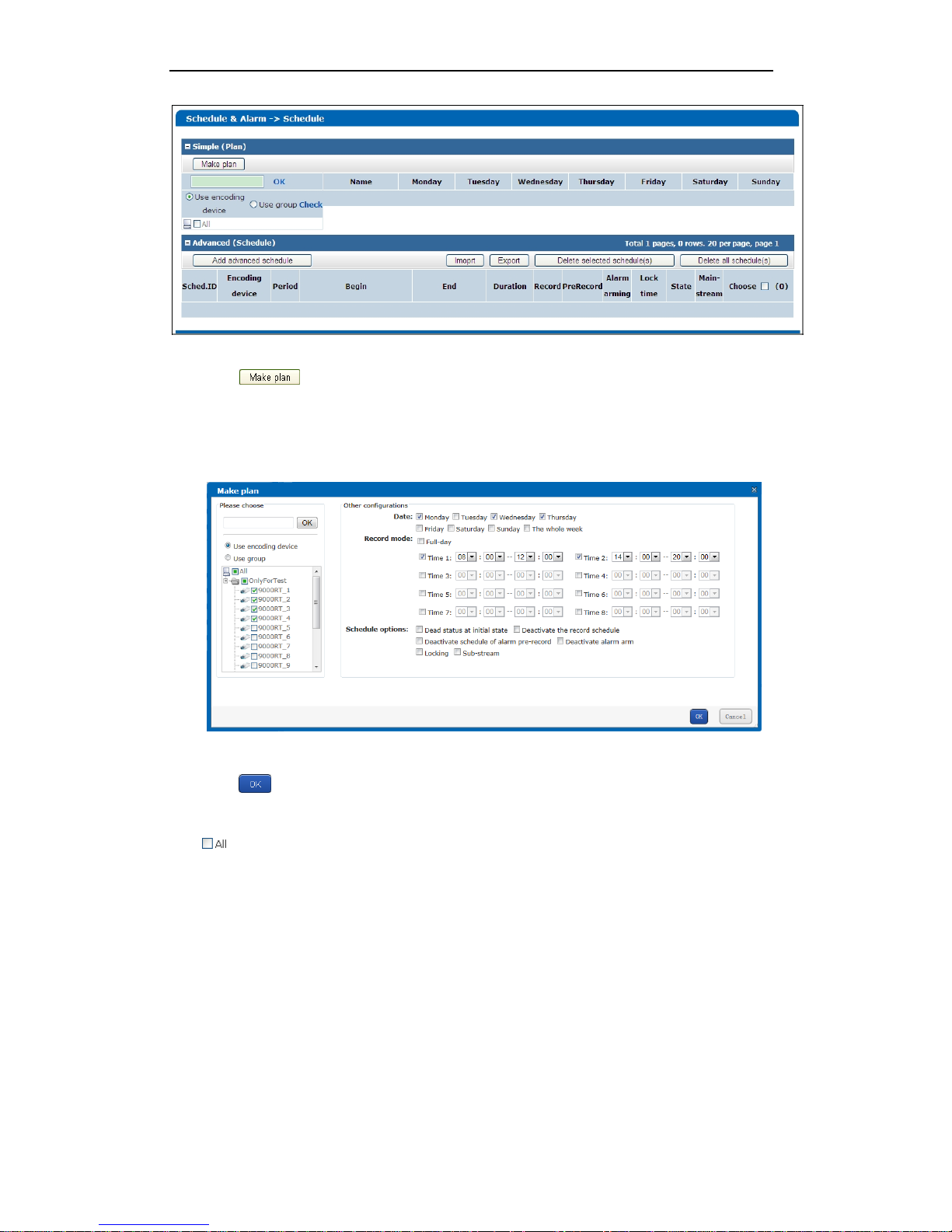
1. Enter the Schedule Settings interface.
Schedule & Alarm>Schedule
Page 69
Quick Operation Guide of 81 Series Storage System
64
Figure 10. 9 Schedule Settings
2. Click to configure the record schedule. Select the decoding device(s) for editing
schedule. Select the day(s) of the week to and set full-day or customized time periods schedule
for the day(s). Set the schedule options for the record schedule.
Note: Up to 8 time periods can be configured for each day.
Figure 10. 10 Configure Record Schedule
3. Click to confirm the settings.
4. Repeat the steps 2-3 to configure the schedule settings for other encoding devices or just check
to configure the same settings for all the devices.
10.4 Live View and Playback
10.4.1 Live View
Before you start:
1. Add trusted sites. On the IE browser menu bar, navigate to Tools > Internet Options > Security >
Page 70

Quick Operation Guide of 81 Series Storage System
65
Trusted sites and click to add the IP address of the CVR system to the list of
trusted sites.
2. On the IE browser menu bar, navigate to Tools > Internet Options > Security > Custom level to
enable the all the ActiveX and plug-ins.
Figure 10. 11 Add Trusted Sites
Figure 10. 12 Enable ActiveX
Steps:
1. Enter Encoding Device List interface.
Live View & Record>Device
Page 71

Quick Operation Guide of 81 Series Storage System
66
Figure 10. 13 Encoding Device List
2. Select an encoding device by checking checkbox in the Select item. Click to
view the live video of the encoding device.
Note: You need to install the plug-in before viewing the live video.
10.4.2 Searching & Playing Back Record Files
Steps:
1. Enter the Record Search interface.
Play & Download>Record Search
Figure 10. 14 Record Search
2. Click and set the search conditions in the pop-up dialog box. Select the
encoding device(s) for record search, set the start time and end time and choose the record
type. Click to search the results.
Page 72

Quick Operation Guide of 81 Series Storage System
67
Figure 10. 15 Search Record Files
3. Select the record file(s) by checking checkbox in the Choose item and click to play
back the record file(s).
Figure 10. 16 Search Result
Page 73

Quick Operation Guide of 81 Series Storage System
68
Chapter 11 Appendix
IE6, IE7, IE8 and IE9 browsers are supported by the storage system.
The default IP address of Data NIC is 192.168.0.100, and the default working mode is
Active-backup.
If you forget the IP address of the device, you can obtain it by inputting command “ifconfig” in
the Hyper Terminal(Baud rate should be set as 115200).
You may enter the manage system through https://10.254.254.254:2004, with the user name
web_admin and default password 123.
It is recommended to connect two network interfaces to the Ethernet network when the
storage device are equipped with several Gigabit NICs.
After you modifying the IP address of an network interface, the Management system may be
disconnected. If so, please log in again with the new IP address.
If you forget the modified IP address, please configure a PC with IP address of 10.254.254.xxx,
then you can check and modify the IP address of Gigabit Network interface by connecting the
PC with the Manage NIC directly with address https://10.254.254.254:2004.
0900001030702
 Loading...