

HikRobot HD Zoom Camera Module Technical Manual
HikRobot HD Zoom Camera Module
Technical Manual
V1.0

HikRobot HD Zoom Camera Module Technical Manual
Table of Contents
Chapter 1 Overview................................................................................. 3
1.1 Product Overview ......................................................................................... 3
1.2 Specifications ............................................................................................... 4
Chapter 2 Interface Description .............................................................. 6
Chapter 3 Communication Protocols ...................................................... 9
3.1 Application Mode for HD Zoom Camera Module ......................................... 9
3.2 RS-232 Serial Port Communication Protocol ................................................ 9
3.2.1 RS-232 Serial Port Command Interface .................................................................. 11
3.2.2 RS-232 Serial Port Search Command Interface ....................................................... 17
3.3 RS-485 Communication Protocol ................................................................ 19
3.3.1 PELCO-D Protocol ................................................................................................... 19
3.3.2 PELCO-P Protocol .................................................................................................... 23
3.3.3 HIK Protocol ............................................................................................................ 26
Chapter 4 Network ................................................................................ 32
4.1 Setting the Network camera over the LAN ................................................. 32
4.1.1 Wiring over the LAN ............................................................................................... 32
4.1.2 Detecting and Changing the IP Address ................................................................. 32
4.2 Accessing by Web Browsers ....................................................................... 33
4.3 Live View Page ........................................................................................... 35
4.4 Operating PTZ Control ................................................................................ 36

HikRobot HD Zoom Camera Module Technical Manual
Chapter 1 Overview
1.1 Product Overview
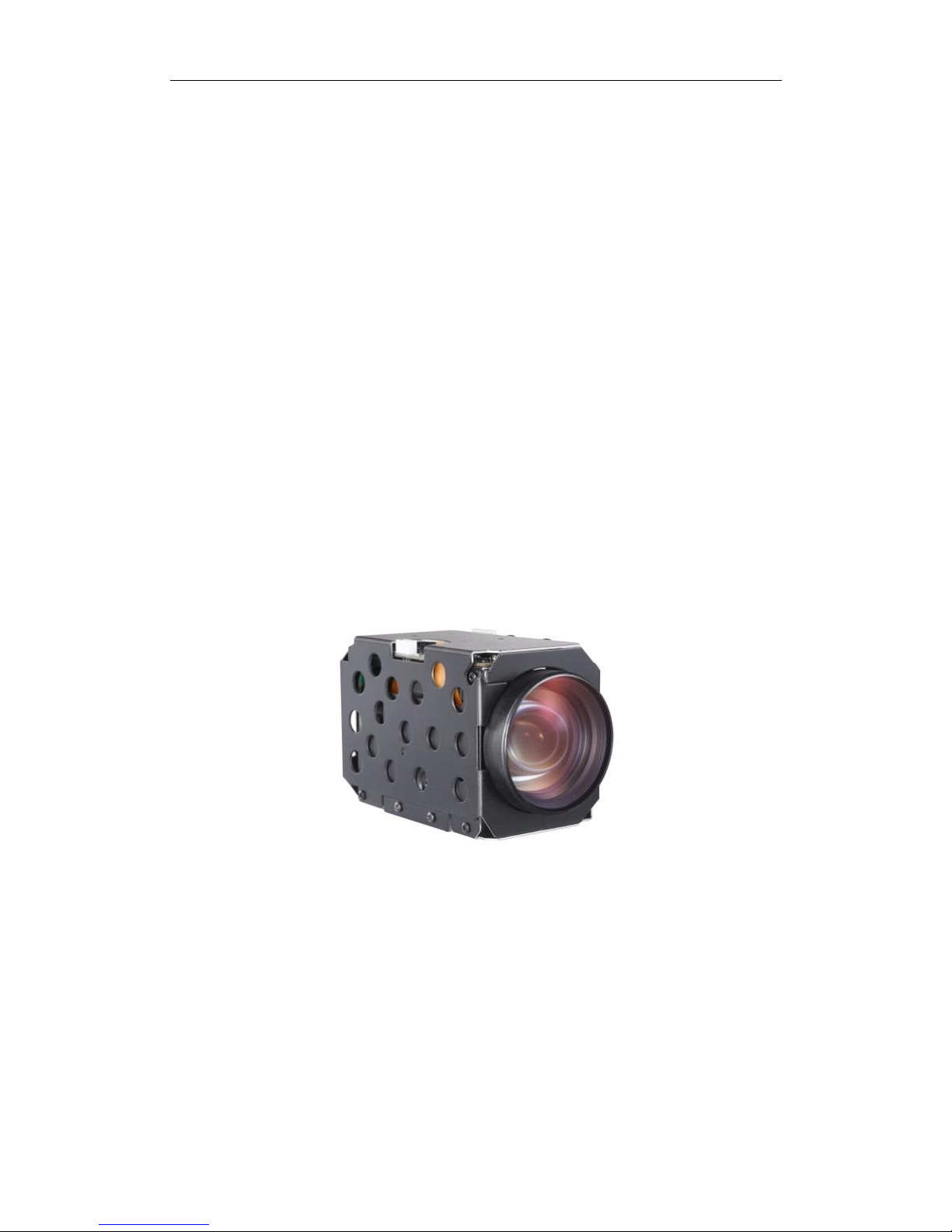
In response to growing demand for high-quality, high-resolution images, the UAV-CZN / UAV-CZD Series
offers a range of 12x to 37x optical zoom lens options with outstanding features for surveillance,
intelligent traffic, unmanned vehicles, photo booths, police vehicles, low vision and videoconferencing
applications.
UAV-CZN / UAV-CZD Series covers a range of products HD , Full-HD and Ultra HD (4K), and with or
without analog (HD) video output, allowing you to select the right camera according to your specific
and varying needs. With excellent built-in auto focus and auto exposure technologies, the zoom camera
module can focus accurately and quickly to mostly improve exposure effect. Besides, it has good low
illumination performance and small size with low power consumption.
Adopting superior encoding and compression technologies, UAV-CZN Series can highly reduce
compression loss. With same image quality requirement, it lowers the bitrate and reduces transmission
bandwidth and occupies less storage space.

HikRobot HD Zoom Camera Module Technical Manual
1.2 Specifications
UAV-CZD3002
UAV-CZD1202-N
UAV-CZN3002-H
UAV-CZD2302-N
UAV-CZD3702-N
UAV-CZN2308
UAV-CZN3708
Camera
Image
sensor
Type
1/2.8-type Exmor CMOS
1/1.8-type Exmor CMOS
1/1.7-type Exmor CMOS
Number of
effective
pixels
Approx. 2.3Megapixels
Approx. 2.1 Megapixels
Approx. 12 Megapixels
Image size (H x V)
1920 x 1080, 1280 x 720, 720 x 480, 720 x 576
4096×2160, 3840×2160, 072×1728,
2560×1440, 1920×1080, 1920×720
Lens
30x optical zoom
12x optical zoom
30x optical zoom
23x optical zoom
37x optical zoom
23x optical zoom
37x optical zoom
f=4.5 mm (wide)
to 135.0 mm
(tele)
f=3.9 mm (wide) to
46.8mm (tele)
f=4.5 mm (wide) to
135.0 mm (tele)
f=5.9 mm (wide) to
135.7 mm (tele)
f=5.7mm (wide) to
210 mm (tele)
f=5.9 mm (wide)
to 135.7 mm
(tele)
f=5.7mm (wide)
to 210 mm (tele)
F1.6 to F4.4
F1.6 to F2.8
F1.6 to F4.4
F1.5 to F3.4
F1.5 to F4.5
F1.5 to F3.4
F1.5 to F4.5
IR- CUT
No IR- CUT
IR-CUT
IR-CUT & Defog
Filter
IR-CUT
IR-CUT & Defog
Filter
Digital zoom
12x
12X
Angle of view (H)
65.1°(wide end)
to 2.34°(tele end)
72°(wide end) to
6.5°(tele end)
65.1°(wide end) to
2.34°(tele end)
59.8°(wide end) to
3.0°(tele end)
61.6°(wide end) to
2.0°(tele end)
59.8°(wide end)
to 3.0°(tele end)
61.6°(wide end)
to 2.0°(tele end)
Minimum object
distance
10 mm (wide end) to 1,000 mm (tele end) (Default: 100 mm)/
Sync system
Internal
N/A
Minimum
illumination
Color: 0.05Lux @
(F1.6,AGC ON)
B/W: 0.01Lux @
(F1.6,AGC ON)
Color: 0.05Lux @
(F1.6,AGC ON)
Color: 0.05Lux @
(F1.6,AGC ON)
B/W: 0.01Lux @
(F1.6,AGC ON)
Color: 0.005Lux @ (F1.5,AGC ON)
B/W: 0.0005Lux @ (F1.5,AGC ON)
Color: 0.05Lux @ (F1.5,AGC ON)
B/W: 0.01Lux @ (F1.5,AGC ON)
S/N ratio
More than 52 dB
Signal
system
HD
1080p/30, 1080p/25,720p/30, 720p/25
1080p/30, 1080p/25,720p/30, 720p/25
1080p/60, 1080p/50,720p/60, 720p/50
50HZ:25fps(4096X2160)
60HZ:30fps(4096X2160)
50HZ:25fps(3840X2160)
60HZ:30fps(3840X2160)
SD
NTSC, PAL
NTSC, PAL
Video
output
HD
Digital:Y/Cb/Cr
4:2:2 via LVDS
(Signal format
conforms to
SMPTE296.)
Digital:Y/Cb/Cr
4:2:2 via LVDS
(Signal format
conforms to
SMPTE296.)
H.264/H.265 via
Ethernet
Digital: HDMI
H.264/H.265 via
ethernet
Digital:Y/Cb/Cr
4:2:2 via LVDS
(Signal format
conforms to
SMPTE296.)
H.264/H.265 via
Ethernet
Analog:TVI
Digital:Y/Cb/Cr
4:2:2 via LVDS
(Signal format
conforms to
SMPTE296.)
H.264/H.265 via
Ethernet
H.264/H.265 via ethernet
SD
VBS
Camera control
interface
VISCA (CMOS 5 V
level) Baud rate:
9.6 Kbps, 19.2
Kbps, 38.4 Kbps,
Stop bit: 1 bit
VISCA (CMOS 5 V level) Baud rate: 9.6 Kbps, 19.2 Kbps, 38.4 Kbps, Stop bit: 1 bit
PELCO-D Baud rate: 2.4 Kbps, 4.8 Kbps, 9.6 Kbps (Default), 19.2 Kbps, 38.4 Kbps,
57.6 Kbps, 76.8.4 Kbps, 115.2 Kbps, Data bit: 8, Stop bit: 1 bit Via RS-485
HIKSDK
PELCO-D Baud rate: 2.4 Kbps, 4.8
Kbps, 9.6 Kbps (Default), 19.2 Kbps,
38.4 Kbps, 57.6 Kbps, 76.8.4 Kbps,
115.2 Kbps, Data bit: 8, Stop bit: 1
bit Via RS-485
HIKSDK
Electronic shutter
speed
1/1 to 1/30,000 s
White balance
Auto/Manual/ATW/Indoor/Outdoor/Daylight lamp/Sodium lamp
Gain
Auto/Manual (-3 dB to +28 dB, +2 dB step/total 16 steps)
AE control
Auto, Manual, Priority mode (shutter priority & iris priority)
Focusing system
Auto, One-push AF, Manual, Infinity, Interval AF, Zoom Trigger AF
HighLight
compensation
Yes
Backlight
compensation
Yes

HikRobot HD Zoom Camera Module Technical Manual
Aperture control
Auto /Manual 16 steps
Preset
N/A
255 positions
WDR
Yes (On/Off/Auto)
De-Fog
Yes
Yes (with Filter)
Yes
Yes (with Filter)
Auto ICR
Yes
N/A
Yes
Spherical privacy
zone masking
N/A
Yes
Noise reduction
Yes
Motion detection
N/A
Yes
Alarm
N/A
Yes
Picture effects
Yes (E-Flip, Mirror image)
Title display
Yes (20 characters/line, max. 10 lines)
Network
Protocols
N/A
TCP/IP, UDP, ICMP, HTTP, HTTPS, FTP, DHCP, DNS, DDNS, RTP, RTSP, RTCP, PPPoE, NTP, UPnP, SMTP, SNMP, IGMP, 802.1 X,
QoS, IPv6
System Compatibility
N/A
ONVIF (Profile S, Profile G), PSIA, CGI, ISAPI
On-board storage
N/A
N/A
Built-in TF slot, up
to 128 GB
N/A
N/A
Built-in TF slot, up to 128 GB
General
Operating Conditions
14˚F to +140˚F (-10°C to +60°C) , Humidity 95% or less (non-condensing)
Power requirements
12.0 VDC ±10%
Power
consumption
2.5 W (zoom/focus inactive) / 4.5 W (zoom/ focus active)
Weight
300g
270g
300g
346g
398g
346g
398g
Dimensions (W x H x D)
50*60*97.4
52.6*67*102.3mm
50*60*97.4
57*67*119
63*67*136
57*67*119
63*67*136

HikRobot HD Zoom Camera Module Technical Manual
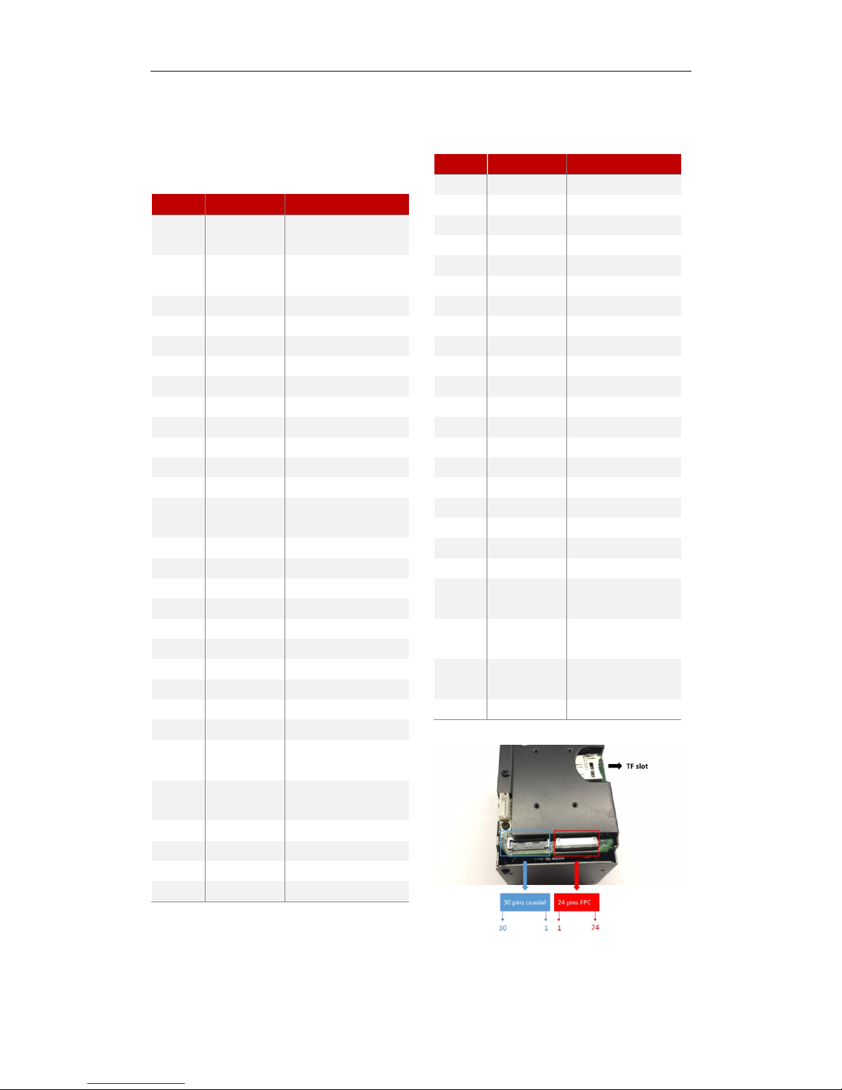
Chapter 2 Interface Description
PIN Assignments of UAV-CZD3002
30-pin Micro Coaxial
Connector: USL00-30L-C (KEL Corp)
PIN
NO.
NAME
DESCRIPTION
1
NC
2
NC 3
CVBS 4
NC 5
NC 6
RSTN
RESET:LOW GND, NORMAL: OPEN 3.3V
7
GND 8
GND 9
GND 10
GND 11
GND 12
GND
13
DC IN
9 to 12V DC
14
DC IN
9 to 12V DC
15
DC IN
9 to 12V DC
16
DC IN
9 to 12V DC
17
DC IN
9 to 12V DC
18
RXD1
3.3V TTL (LOW: MAX 0.8, HIGH: MIN 2.0)
19
TXD1
3.3V TTL (LOW: MAX 0.8, HIGH: MIN 2.0)
20
GND 21
RXIN0- 22
RXIN0+ 23
RXIN1- 24
RXIN1+ 25
RXIN2- 26
RXIN2+ 27
RXCLKIN- 28
RXCLKIN+
29
RXIN3-
30
RXIN3+
PIN Assignments of UAV-
CZN2308/3708
36-pin 0.5mm FPC connector
Connector:FH12- 36S-0.5SH (55) Hirose
PIN
NO.
NAME
DESCRIPTION
1
DC IN
9 TO 12V DC POWER INPUT
2
DC IN
9 to 12V DC Power Input
3
DC IN
9 TO 12V DC POWER INPUT
4
GND
Power GND
5
GND
POWER GND
6
CVBS
Analog Video Output
7
GND
POWER GND
8
LINE_OUT
Audio Output
9
GND
POWER GND
10
LINE_IN
Audio Input
11
PWFBOUT
NETWORK OUTPUT
12
TPTX+
100 M Network TPTX+
13
TPTX-
100 M NETWORK TPTX-
14
TPRX+
100 M Network TPRX+
15
TPRX-
100 M NETWORK TPRX-
16
GND (for DGND)
GND
17
LINK#
NETWORK INDICATOR
18
ACT#
Network Indicator
19
ALARM_OUT
ALARM OUTPUT
20
ALARM_IN
Alarm Input
21
GND
POWER GND
22
SD_EN
SD Card Power On
23
SD1_WP
SD CARD INPUT
24
SD1_CD
SD Card Output
25
SD_CLK
SD CARD CLOCK CABLE
26
SD_CMD
SD Card Command Cable
27
SD_DATA3
SD CARD DATA CABLE
28
SD_DATA2
SD Card Data Cable
29
SD_DATA1
SD CARD DATA CABLE
30
SD_DATA0
SD Card Data Cable
31
GND
POWER GND
32
RS485 -
33
RS485 +
34
232_TX
TTL3.3V CMOS5V
35
232_RX
TTL3.3V CMOS5V
36
RESET
RESET:LOW GND, NORMAL: OPEN
3.3V

HikRobot HD Zoom Camera Module Technical Manual
PIN Assignments of UAV-CZD1202/2302/3702-N
30-pin Micro Coaxial
Connector: USL00-30L-C (KEL Corp)
PIN NO.
NAME
DESCRIPTION
1
NC 2
NC 3
CVBS
4
NC/
TVI_OUT
UAV-CZD2302-N: TVI_OUT
UAV-CZD1202-N, UAV-CZD3702-N: NC
5
NC 6
RSTN
RESET:LOW GND, NORMAL: OPEN 3.3V
7
GND 8
GND 9
GND 10
GND 11
GND 12
GND 13
DC IN
9 to 12V DC
14
DC IN
9 to 12V DC
15
DC IN
9 to 12V DC
16
DC IN
9 to 12V DC
17
DC IN
9 to 12V DC
18
RXD1
3.3V TTL (LOW: MAX 0.8, HIGH: MIN 2.0)
19
TXD1
3.3V TTL (LOW: MAX 0.8, HIGH: MIN 2.0)
20
GND 21
RXIN0- 22
RXIN0+ 23
RXIN1- 24
RXIN1+ 25
RXIN2- 26
RXIN2+
27
RXCLKIN-
28
RXCLKIN+
29
RXIN3- 30
RXIN3+
Network /485 Pin Assignments (A1251-08AWB)
PIN NO
NAME
DESCRIPTION
1
TX+
NETWORK OUTPUT DATA
2
TX-
Network output data
3
RX+
NETWORK RECEPTION DATA
4
RX-
Network reception data
5
GND 6
485_D+
7
485_D- 8
GND
HikRobot HD Zoom Camera Module Technical Manual
2.3 PIN Assignments of UAV-CZN3002-H
30-pin Micro Coaxial
Connector: LVX-A (30) SFYG+ (HONDA TSUSHIN
KOGYO Corp)
PIN NO.
NAME
DESCRIPTION
1
RXD_3
3.3V TTL(LOW: MAX 0.8, HIGH:
MIN 2.0)
2
TXD_3
3.3V TTL(LOW: MAX 0.8, HIGH:
MIN 2.0)
3
DC IN
9 TO 12V DC
4
DC IN
9 to 12V DC
5
DC IN
9 TO 12V DC
6
DC IN
9 to 12V DC
7
DC IN
9 TO 12V DC
8
GND 9
GND 10
GND 11
GND 12
TMDSDP2
13
TMDSDN2
14
GND 15
TMDSDP1
16
TMDSDN1
17
GND 18
TMDSDP0
19
TMDSDN0
20
GND 21
TMDSCLKP
22
TMDSCLKD
23
GND 24
HDMI_CEC
25
DDC_SCL
3.3V TTL(LOW:MAX 0.8,
HIGH:MIN 2.0)
26
DDC_SDA
3.3V TTL(LOW:MAX 0.8,
HIGH:MIN 2.0)
27
GND
28
HDMI_HPD
29
5V_HDMI_OUT
30
GND
24-pin 0.5mm FPC connector
Connector: FPC 0.5S-1X-24PWB
PIN NO.
NAME
DESCRIPTION
1
DC IN
9 to 12V DC
2
DC IN
9 TO 12V DC
3
DC IN
9 to 12V DC
4
GND 5
GND
6
CVBS 7
GND 8
TX+ 9
TX- 10
RX+ 11
RX- 12
GND 13
LED_LINK
14
LED3 15
ALARM_OUT
16
ALARM_IN
17
GND
18
GND 19
485_D- 20
485_D+
21
UART3D_TXD
3.3V TTL(LOW: MAX 0.8,
HIGH: MIN 2.0)
22
UART3D_RXD
3.3V TTL(LOW: MAX 0.8,
HIGH: MIN 2.0)
23
MRESET
RESET:LOW GND, NORMAL:
OPEN 3.3V
24
NC
HikRobot HD Zoom Camera Module Technical Manual
Chapter 3 Communication Protocols
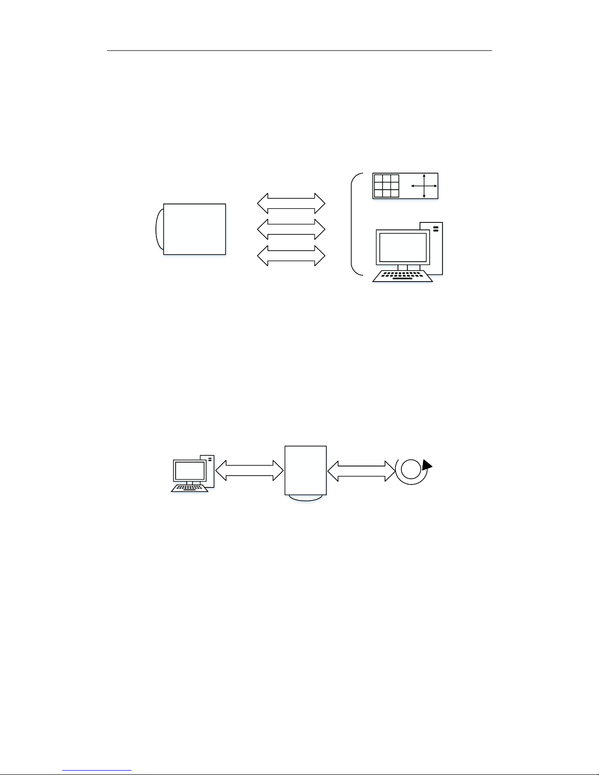
3.1 Application Mode for HD Zoom Camera Module
Users can configure parameters of the zoom camera module via Serial port Ethernet.
RS-485
RS-232
NetWork
Figure 1 communication bet ween camera and controller
Communication between zoom camera module and controller is through RS-232 interface, RS-485
interface and network. The communication protocols are HIKVISION protocols (compatible with SONY
VISCA protocol) and PELCO.
UAV-CZN Series has another usage. The zoom camera connects to controller via network cable, and
connects to PAN/TILT devise via RS-232/RS-485. The zoom camera communicates to the controller, at
the same time it controls the PAN/TILT device.
RS-232/RS-485
NetWork
M
PAN/TILT
device
3.2 RS-232 Serial Port Communication Protocol
HIKVISION RS-232 Communication Protocol Characteristic:
RS-232 Serial Port Answering Remark
Answer: X0 4Y FF
Execute Command: X0 5Y FF
Search and Return: X0 5Y FF
X = 9 – F Zoom Camera Module Address +8; Y socket number.
RS-232 Serial Port Error Information Remark

HikRobot HD Zoom Camera Module Technical Manual
X0 6Y 01 FF Command Bytes Length Error (>14 Bytes)
X0 6Y 02 FF Command Error
X0 6Y 03 FF Command Buffer Full
X0 6Y 41 FF Command Non-execution
X = 9 – F Zoom Camera Module Address +8; Y socket number.

HikRobot HD Zoom Camera Module Technical Manual
3.2.1 RS-232 Serial Port Command Interface
Command
Command Package
Description
RS-232 Serial Port Answering Remark
Answer: X0 4Y FF
Execute Command: X0 5Y FF
Search and Return: X0 5Y FF
X = 9 – F Zoom Camera Modul e Address +8; Y socket number.
RS-232 Serial Port Error Information Remark
X0 6Y 01 FF Command Bytes Length Error (>14 Bytes)
X0 6Y 02 FF Command Error
X0 6Y 03 FF Command Buffer Full
X0 6Y 41 FF Command Non-execution
X = 9 – F Zoom Camera Module Address +8; Y socket number.
Address Setting
88 30 01 FF
Return 88 30 02 FF;
Return to Zoom Camera Module Address +1
Zoom
8x 01 04 07 00 FF
T/W Stop
8x 01 04 07 02 FF
The default speed: configured in front-end
8x 01 04 07 03 FF
8x 01 04 07 2p FF
T/W Operation;
p=0 (Low) to 7 (High), stands for zoom speed
8x 01 04 07 3p FF
8x 01 04 47 0p 0q 0r 0s FF
0xpqrs: zoom to the specified coordinates:
0x0000 to 0x7ac0
8x 01 04 47 0p 0q 0r 0s 0m 0n 0s 0t
FF
Zoom to the specified coordinates;
pqrs: zoom coordinates (
Appendix 1 Ratio Table);
xmnst: focus coordinates
8x 01 04 06 02 FF
8x 01 04 06 03 FF
Digital Zoom ON/OFF
Focus
8x 01 04 08 00 FF
N/F Stop
8x 01 04 08 02 FF
The Default Focus Speed.
8x 01 04 08 03 FF
8x 01 04 48 0p 0q 0r 0s FF
Focus to the specified coordinates. 0xpqrs:
0x1000 to 0xC000
8x 01 04 38 02 FF
Focus Auto/Manual Mode
8x 01 04 38 03 FF
8x 01 04 38 10 FF
Focus Auto/Manual Mode Switch
8x 01 04 18 01 FF
One Focus Mode
8x 01 04 18 02 FF
Infinity Focus Mode

HikRobot HD Zoom Camera Module Technical Manual
8x 01 04 28 0p 0q 0r 0s FF
0xpqrs: Min. focus range (Appendix 4 Min. Focus Distance
Table)
Auto Focus Sensitivity
8x 01 04 58 02 FF
Focus Sensitivity Common/Low
8x 01 04 58 03 FF
Zoom Came Module
Initialization
8x 01 04 19 01 FF
Len Initialization
White Balance
8x 01 04 35 00 FF
Auto White Balance Mode 1
8x 01 04 35 01 FF
Indoor White Balance Mode
8x 01 04 35 02 FF
Outdoor White Balance Mode
8x 01 04 35 04 FF
Auto White Balance Mode 2
8x 01 04 35 05 FF
Manual White Balance Mode
8x 01 04 35 07 FF
Sodium Lamp White Balance Mode
8x 01 04 35 08 FF
Fluorescent Lamp White Balance Mode
White Balance R Gain
8x 01 04 03 00 FF
R Default Gain
8x 01 04 03 02 FF
R Gain +
8x 01 04 03 03 FF
R Gain -
8x 01 04 43 00 00 0p 0q FF
Set R Gain value;
p,q: R Gain(00 to FF)
White Balance B Gain
8x 01 04 04 00 FF
B Default Gain
8x 01 04 04 02 FF
B Gain +
8x 01 04 04 03 FF
B Gain -
8x 01 04 44 00 00 0p 0q FF
Set B Gain value;
p,q: B Gain(00 to FF)
Exposure Mode
8x 01 04 39 00 FF
Auto Exposure Mode
8x 01 04 39 03 FF
Manual Exposure Mode
8x 01 04 39 0A FF
Shutter Priority Mode
8x 01 04 39 0B FF
Iris Priority Mode
Shutter
8x 01 04 0A 00 FF
Default Shutter Speed
8x 01 04 0A 02 FF
Shutter Speed +
8x 01 04 0A 03 FF
Shutter Speed -
8x 01 04 4A 00 00 0p 0q FF
Set shutter speed;
0xpq: shutter (Appendix 5 Shutter Level Table, valid in
shutter priority mode and manual exposure mode
Iris
8x 01 04 0B 00 FF
Iris Size Restoration
8x 01 04 0B 02 FF
Iris +
8x 01 04 0B 03 FF
Iris -
8x 01 04 4B 00 00 0p 0q FF
The specified iris size;
0xpq: 0 to 0x0f
Gain
8x 01 04 0C 00 FF
Gain Restoration
8x 01 04 0C 02 FF
Gain +
8x 01 04 0C 03 FF
Gain -

HikRobot HD Zoom Camera Module Technical Manual
8x 01 04 4C 00 00 0p 0q FF
The specified gain value;
0xpq: Gain Value (Appendix 2 Ratio Table ( 23X )
Zoom
Ratio
Table
Ratio
Position (0
to 0x4000,
hexadecimal
number.)
Ratio
Position (0
to 0x4000,
hexadecimal
number.)
1
0x00
19
0x3E24
2
0x14CC
20
0x3EB8
3
0x1E87
21
0x3F43
4
0x2483
22
0x3FA5
5
0x28B4
23
0x4000
6
0x2BDF
46
0x6000
7
0x2E6E
69
0x6a80
8
0x3093
92
0x7000
9
0x3276
115
0x7300
10
0x3410
138
0x7540
11
0x35A1
161
0x76c0
12
0x370A
184
0x7800
13
0x3851
207
0x78c0
14
0x3989
230
0x7980
15
0x3AA7
253
0x7a00
16
0x3BAE
276
0x7ac0
17
0x3C9B
18
0x3D68
Appendix 3 Gain Level Table, valid in manual
exposure mode)
8x 01 04 2C 0p FF
Gain Limit;
0xP: (0x0 to 0xF, 16 levels) (valid in auto exposure mode,
iris priority mode and shutter priority mode)
Slow Shutter
8x 01 04 5A 0P FF
P: 2 Slow Shutter ON; 3 Slow Shutter OFF
This command is for slow shutter ON/OFF, see Hikvision
extended protocol for level setting.
Exposure Compensation
8x 01 04 3E 02 FF
Exposure Compensation ON/OFF
8x 01 04 3E 03 FF
8x 01 04 0E 00 FF
Default Exposure Compensation
8x 01 04 0E 02 FF
Exposure Compensation +
8x 01 04 0E 03 FF
Exposure Compensation -
8x 01 04 4E 00 00 0p 0q FF
The specified exposure compensation; 0xpq: (0x00 to
0x09, 10 levels) (the pre-condition is Exposure
Compensation ON, valid after exposure compensation
level except manual exposure compensation is
configured.)

HikRobot HD Zoom Camera Module Technical Manual
Backlight Compensation (BLC)
8x 01 04 33 02 FF
BLC ON/OFF
(Valid in auto exposure mode, iris priority mode and
shutter priority mode only.)
Refer to Note 3.
8x 01 04 33 03 FF
Definition
8x 01 04 02 00 FF
Default Definition
8x 01 04 02 02 FF
Definition +
8x 01 04 02 03 FF
Definition -
8x 01 04 42 00 00 0p 0q FF
The specified definition;
0xpq: 0x00 to 0A, 11 levels
Mirror Horizontally
8x 01 04 61 02 FF
8x 01 04 61 03 FF
Mirror Horizontally ON/OFF
Mirror Vertically
8x 01 04 66 02 FF
8x 01 04 66 03 FF
Mirror Vertically ON/OFF
GAMMA (Contrast)
8x 01 04 5B 0p FF
Gamma Curve;
0 to 0xA, 11 levels
ICR Filter
8x 01 04 01 02 FF
ICR Switched to Night
8x 01 04 01 03 FF
ICR Switched to Day
Auto ICR
8x 01 04 21 00 00 0p 0q FF
Auto ICR Sensitivity
pq: Set ICR sensitivity (Appendix 7 Auto ICR Switch
Sensitivity Table)
8x 01 04 51 0p FF
0p:
02 Auto (Auto ICR takes effect when exposure mode is
auto, iris priority and shutter priority.)
03 Manual
04 Continuous
05 External Trigger Mode
(03 04 05 are all passive ICR switches without specific
differences)
06 Auto White Light Mode (auto ICR mode for white light
scenes)
OSD (see constraint condition
in Note 1)
8x 01 04 73 1L 00 nn pp qq
rr 00 00 00 00 00 FF
L: Line
nn pp: x starting coordinates
qq rr: y coordinates
8x 01 04 73 2L mm nn pp qq
rr ss tt uu vv ww FF
L: Line
Mnpqrstuvw: the first ten characters
8x 01 04 73 3L mm nn pp qq
rr ss tt uu vv ww FF
L: Line
mnpqrstuvw: the last ten charact ers
8x 01 04 74 2f FF
Display
8x 01 04 74 3f FF
Clear
Saturation
8x 01 09 16 0p FF
P: Saturation Level
0-0xA, 11 levels
HLC
8x 01 09 17 0p FF
P: 0 OFF, 1 ON
(HLC is invalid in manual exposure mode, see Note 3)

HikRobot HD Zoom Camera Module Technical Manual
Hikvision
Expanded
Functions
Slow Shutter
Limit
8x 01 09 2a 0p FF
P: 0 to 9
(Use it cooperatively with slow shutter, see Note 4.)
SMARTIR
8x 01 09 28 0P FF
P: 0 to 0xf
see Note 3
Ratio Display
ON/OFF
8x 01 09 06 0P FF
P: 3 OFF, 2 ON
Zoom, Focus,
Preset Mode
8x 01 09 50 0p FF
P: 0: Zoom camera module has finished. 1: Speed dome
should send the corresponding command.
Default: 0.
E.g., Click Zoom + in client.
In 0 mode: the zoom camera module performs Zoom+
action immediately.
In 1 mode: the speed dome receives the Zoom+ command
through RS-485 and it s ends 8x 01 04 07 2p FF command
to the zoom camera module, and then the zoom camera
module performs Zoom+ action.
Digital Zoom
Limit
8x 01 09 12 22 0p 0q FF
0xpq:
1-0xC
Optical Max.
Ratio Limit
8x 01 09 12 21 0p 0q FF
0x pq: the Max. Optical Ratio
Optical Min.
Ratio Limit
8x 01 09 12 23 0p 0q FF
0x pq: the Min. Optical Ratio
Defog
8x 01 09 31 0p FF
P: 0 OFF, non-zero ON
Regional
Exposure
8x 01 09 55 0p 0q 0r 0s FF
0xpqrs: 0x0000 to 0xFFFF, every bit matches a window. Up
to 16 windows can be configured. See Note 2 for detailed
relations.
Regional Focus
8x 01 09 5A 0p 0q 0r 0s FF
0xpqrs: 0x0000 to 0xFFFF, every bit matches a window. Up
to 16 windows can be configured. See Note 2 for detailed
relations.
Min. Iris Limit
8x 01 09 56 0p 0q 0r 0s FF
0xpqrs: 0x0000 to 0x0064, the value is lager, the iris is
larger. Valid in auto exposure mode and shutter priority
mode.
Max. Iris Limit
8x 01 09 57 0p 0q 0r 0s FF
0xpqrs: 0x0000 to 0x0064, the value is lager, the iris is
larger. Valid in auto exposure mode and shutter priority
mode.
Min. Shutter
Limit
8x 01 09 59 0p 0q 0r 0s FF
0xpqrs: 0x0005 to 0x0019. Valid in auto exposure mode
and iris priority mode.
Max. Shutter
Limit
8x 01 09 58 0p 0q 0r 0s FF
0xpqrs: 0x0005 to 0x0019. Valid in auto exposure mode
and iris priority mode.
Defocus
Detection
ON/OFF
8x 01 09 A0 0p FF
p 0: Defocus Detection OFF;
1: Defocus Detection ON
Optical Ratio
Settings
8x 01 09 AD 0p 0q 0r 0s FF
0xpqrs: the real optical ratio is *1000 and the interval of
optical ratio is 0.1.

HikRobot HD Zoom Camera Module Technical Manual
BLC Area
8x 01 09 62 0p FF
0x0p: 00 Reset (Auto) 02 Up 03Down 04 Left 05Right 06
Middle
(BLC function is valid in auto exposure mode, iris priority
mode and shutter priority mode only.)
Low
Temperature
Settings
8x 01 09 A7 0p FF
P: 0 OFF
1 ON
Set Zoom Limit
8x 01 09 66 0p 0q 0r 0s 0m
0n 0s 0t FF
0x pqrs: Min. Zoom Coordinates
0x mnst: Max. Zoom Coordinates
Limited to the specified position (0 to 0x4000)
Note 1:
Up to four lines are supported for overlay (the No. is from 0 to 3). Only one line can be displayed
in NTSC 1920*1080 resolution mode and up to 20 English characters and 10 Chinese characters
for each line.
It displays only one line and 0 to 0xxx can be set for y-axis. When displaying multiple lines, the
difference value of Min. y-axis value and Max. Y-axis value cannot be more than 8. In x-axis, there
are multiples of 16 (o included) and the Max. Can be set as (44*16 – characters quantity for this
line*16).
Up to 20 characters can be set for each line. The last characters must be set as 0x20 if the character
quantity is less than 20.
E.g. 81 01 04 73 21 31 31 31 20 20 20 20 20 20 20 ff
81 01 04 73 31 20 20 20 20 20 20 20 20 20 20 ff
It is 111.
0x20 between the characters are valid.
Supports ASCII and GBK characters.
Note 2:
Regional exposure supports 16 windows. The corresponding relations between command 0xpqrs 16 bits
and image windows are shown below. Bit 0 matches the area No.1 of the image window and bit 15
matches area No.16 of the image window.
P Q R S bit15
bit14
bit13
bit12
bit11
bit10
bit9
bit8
bit7
bit6
bit5
bit4
bit3
bit2
bit1
bit0
16
15
14
13
12
11
10 9 8 7 6 5 4 3 2
1

HikRobot HD Zoom Camera Module Technical Manual
When image mirror is configured, area No. changes together with the image. For example, after
center mirror, the original area No. 16 changes to be area No. 1 and the original area No. 1 changes to
area No. 16.
Note 3:
HLC, BLC and Smart IR, any two of the three functions are not supported at the same time. When one
function is enabled, other two will be disabled.
Note 4:
Slow shutter settings will not take effect when WDR is enabled.
3.2.2 RS-232 Serial Port Search Command Interface
Command
Search Interface
Search Package
Description
ICR ON/OFF Search
8x 09 04 01 FF
y0 50 02 FF
ICR Black/White Mode
y0 50 03 FF
ICR Color Mode
Zoom Position Search
8x 09 04 47 FF
y0 50 0p 0q 0r 0s FF
pqrs: Zoom Position
Digital Zoom O N/OFF
Search
8x 09 04 06 FF
y0 50 02 FF
Digital Zoom ON
y0 50 03 FF
Digital Zoom OFF
Focus Mode Search
8x 09 04 38 FF
y0 50 02 FF
Auto Focus
y0 50 03 FF
Manual Focus
Focus Position Search
8x 09 04 48 FF
y0 50 0p 0q 0r 0s FF
pqrs: Focus Position
Min. Focus Distance
Search
8x 09 04 28 FF
y0 50 0p 0q 0r 0s FF
pqrs: Min. Focus Distance
(Appendix 4 Min. Focus Distance
Table)
White Balance Mode
Search
8x 09 04 35 FF
y0 50 00 FF
Auto White Balance 1
y0 50 01 FF
Indoor White Balance
y0 50 02 FF
Outdoor White Balance

HikRobot HD Zoom Camera Module Technical Manual
y0 50 04 FF
Auto White Balance 2
y0 50 05 FF
Manual White Balance
y0 50 07 FF
Sodium Light White Balance
y0 50 08FF
Fluorescent Lamp White Balance
White Balance R Gain
Search
8x 09 04 43 FF
y0 50 00 00 0p 0q FF
R Gain
White Balance B Gain
Search
8x 09 04 44 FF
y0 50 00 00 0p 0q FF
B Gain
Exposure Mode Search
8x 09 04 39 FF
y0 50 00 FF
Auto
y0 50 03 FF
Manual
y0 50 0A FF
Shutter Priority
y0 50 0B FF
Iris Priority
Slow Shutter Search
8x 09 04 5A FF
y0 50 02 FF
Slow Shutter ON
y0 50 03 FF
Slow Shutter OFF
Shutter Value Search
8x 09 04 4A FF
y0 50 00 00 0p 0q FF
Shutter Value
Iris Value Search
8x 09 04 4B FF
y0 50 00 00 0p 0q FF
Iris Value
Gain Search
8x 09 04 4C FF
y0 50 00 00 0p 0q FF
Gain Value
Gain Limit Search
8x 09 04 2C FF
y0 50 0q FF
Gain Limit Value
Exposure
Compensation ON/OFF
Search
8x 09 04 3E FF
y0 50 02 FF
Exposure Compensation ON
y0 50 03 FF
Exposure Compensation OFF
Exposure
Compensation Gain
Search
8x 09 04 4E FF
y0 50 00 00 0p 0q FF
Exposure Compensation Value
BLC ON/OFF Search
8x 09 04 33 FF
y0 50 02 FF
BLC ON
y0 50 03 FF
BLC OFF
Gamma Search
8x 09 04 5B FF
y0 50 0p FF
P: Gamma Level
Definition Search
8x 09 04 42 FF
y0 50 00 00 0p 0q FF
Definition
ICR Mode Search
8x 09 04 51 FF
y0 50 02 FF
Auto ICR Mode
y0 50 03 FF
Manual ICR Mode
Auto ICR Sensitivity
Search
8x 09 04 21 FF
y0 50 00 00 0p 0q FF
Auto ICR Sensitivity
Left/Right Mirror
ON/OFF Search
8x 09 04 61 FF
y0 50 0p FF
0p: 2 Left/Right Mirror and Center
Mirror
3 Up/Down Mirror and Mirror OFF
Up/Down Mirror
ON/OFF Search
8x 09 04 66 FF
y0 50 0p FF
0p: 2 Up/Down Mirror and Center
Mirror
3 Left/Right Mirror and Mirror OFF
Software Version
Search
81 09 09 00 FF
90 50 mn pq rs tu FF
When r is 0 and vw is year 01 15
03 09 10, the zoom camera
module software version is V1.21
compiled on 09/03/2016.
When r is not 0 and r stands for

HikRobot HD Zoom Camera Module Technical Manual
year 01 15 A3 09, the zoom
camera module software version
is V1.21 compiled on 09/03/2010.
AGC Value Search
8x 09 09 05 FF
y0 50 0p 0q 0r 0s FF
0xpqrs is the return value.
Slow Shutter Level
Search
8x 09 09 5C FF
y0 50 00 00 0p 0q FF
0xpq: Slow Shutter Level (Valid
when slow shutter is ON.)
Zoom Camera Module
ID Search
8x 09 48 4B FF
y0 50 48 4b 0x xx 02 00 02 FF
Zoom Camera Module ID: 0753
Smart IR Level Search
8x 09 09 28 FF
y0 50 0p FF
P: 0-f
System Starting Status
Search
8x 09 09 e0 FF
y0 50 0p FF
P: bit0=1 bit1=1 means starts
successfully.
Regional Exposure
Search
8x 09 09 55 FF
y0 50 0p 0q 0r 0s ff
0xpqrs: 0x0000 to 0xFFFF, every
bit matches a window. Up to 9
windows can be configured. See
Note 2 for detailed relations.
Regional Focus Search
8x 09 09 5A FF
y0 50 0p 0q 0r 0s ff
0xpqrs: 0x0000 to 0xFFFF, every
bit matches a window. Up to 16
windows can be configured. See
Note 2 for detailed relations.
Defog Level Search
8x 09 09 31 FF
y0 50 00 00 0p 0q FF
0xqp: Defog Level
Optical Min. Ratio Limit
Search
8x 09 09 12 22 FF
y0 50 0p 0q FF
Pq: Optical Ratio Limit Value
Optical Max. Ratio Limit
Search
8x 09 09 12 21 FF
y0 50 0p 0q FF
Pq: Optical Ratio Limit Value
Min. Iris Limit
8x 09 09 56 FF
y0 50 0p 0q 0r 0s FF
0xpqrs: Min. Iris Limit
Value
Max. Iris Limit
8x 09 09 57 FF
y0 50 0p 0q 0r 0s FF
0xpqrs: Max. Iris Limit
Value
Min. Shutter Limit
8x 09 09 59 FF
y0 50 0p 0q 0r 0s FF
0xpqrs: Min. Shutter
Value
Max. Shutter Limit
8x 09 09 58 FF
y0 50 0p 0q 0r 0s FF
0xpqrs: Max. Shutter
Value
Low Temperature
Status Search
8x 09 09 A7 FF
y0 50 0p FF
P: 0: Low Temperature OFF
1: Low Temperature ON
Focus Status Search
8x 09 09 E5 FF
y0 50 0p FF
P: 2 Focus Finished
3 Focusing
HLC Search
81 09 09 17 FF
y0 50 0p FF
P: 0 OFF
1 ON
Optical Ratio Value
Search
8x 09 09 AD ff
y0 50 0p 0q 0r 0s FF
0p 0q 0r 0s FF 0xpqrs: 0x03e8 to
0x7d80 (matches 1000 to 32000
in decimal numeral, real optical
ratio value*1000). The interval of
optical ratio is 0.5.

HikRobot HD Zoom Camera Module Technical Manual
3.3 RS-485 Communication Protocol
UAV-CZN Series support PELCO-D, PELCO-P and HIK PTZ protocols, and the zoom camera module will
send protocol command through RS-485 when users perform operations such as PTZ via network.
Currently, the zoom camera module can only receive the commands of HIK extended search and
configuration commands.
3.3.1 PELCO-D Protocol
Communication data format: one start bit, eight data bits, one stop bit, and no check bit.
The default communication baud rate is 9600 bps and the default address is 0.
Pelco-D Command Description
Byte 1
Byte 2
Byte 3
Byte 4
Byte 5
Byte 6
Byte 7
Synchronization
Byte
Address Code
Command
Code 1
Command
Code 2
Data Code 1
Data Code 2
Check Code
1. All numbers in the protocol are hexadecimal numbers.
2. Synchronization byte is always FFH.
3. Address code is the logical address number of the camera which ranges from 00H to FFH.
4. Command code stands for different actions.
5. Data code 1 and data code 2 respectively stand for pan speed and tilt speed (00 to 3FH),
and FFH stands for turbo speed.
6. Check code = MOD [(Byte 2 + Byte 3 + Byte 4 + Byte 5 + Byte 6)/100H].
Pelco-D Commands that Hikvision Network HD Zoom Camera Module Supports
Network zoom camera module sends commands, and the address is 1 (Check code is checked).
Command
Command Package
Description
PTZ Control
0xff,0x01,0x00,0x08,0x00,0xff,0x08
Up
0xff,0x01,0x00,0x10,0x00,0xff,0x10
Down
0xff,0x01,0x00,0x04,0xff,0x00,0x04
Left
0xff,0x01,0x00,0x02,0xff,0x00,0x02
Right
0xff,0x01,0x00,0x0c,0x0f,0x0f,0x2b
Upper Left
0xff,0x01,0x00,0x0a,0x0f,0x0f,0x29
Upper Right
0xff,0x01,0x00,0x14,0x0f,0x0f,0x13
Lower Left
0xff,0x01,0x00,0x12,0x0f,0x0f,0x11
Lower Right
0xff,0x01,0x00,0x20,0x00,0x00,0x21
Zoom +
0xff,0x01,0x00,0x40,0x00,0x00,0x41
Zoom -
0xff,0x01,0x01,0x00,0x00,0x00,0x02
Focus +
0xff,0x01,0x00,0x80,0x00,0x00,0x81
Focus -
0xff,0x01,0x02,0x00,0x00,0x00,0x03
Iris +

HikRobot HD Zoom Camera Module Technical Manual
0xff,0x01,0x04,0x00,0x00,0x00,0x05
Iris -
0xff,0x01,0x00,0x00,0x00,0x00,0x01
Stop
Auxiliary Switch
0xff,0x01,0x00,0x09,0x00,0x02,0x0c
Light ON
0xff,0x01,0x00,0x0b,0x00,0x02,0x0 e
Light OFF
0xff,0x01,0x00,0x09,0x00,0x01,0x0b
Wiper Enabled
0xff,0x01,0x00,0x0b,0x00,0x01 ,0x0d
Wiper Disabled
Preset
0xff,0x01,0x00,0x07,0x00,0x01,0x09
Turn to Preset 001
0xff,0x01,0x00,0x03,0x00,0x01,0x05
Set Preset 001
0xff,0x01,0x00,0x05,0x00,0x01,0x07
Delete Preset 001
Auto Scan
0xff,0x01,0x00,0x07,0x00,0x63,0x6B
Start Auto Scan
0xff,0x01,0x00,0x00,0x00,0x00,0x00
Stop Auto Scan
Track
0xff,0x01,0x00,0x1F,0x00,0x00,0x12
Start Track Record
0xff,0x01,0x00,0x21,0x00,0x00,0x12
Stop Track Record
0xff,0x01,0x00,0x23,0x00,0x00,0x12
Start Track Scan
0xff,0x01,0x00,0x00,0x00,0x00,0x01
Stop Track Scan
Hikvision Extended Function Commands
i. Click to Zoom-in Command Data Form (0xC0)
Command
Header
Speed
Dome
Address
Command
No.
X-axis
Y-axis
Width
Height
Description
FF
ID
C0
Byte 1
Byte 2
Byte 3
Byte 4
Drag the mouse to the position
(x, y), and zoom in the selected
area (the center is (x,y), the
width is w and the height is h) to
a certain ratio decided by the
speed dome.
Note:
The standard PELCO-D protocol is 0xFF-ID-CMD1-CMD2-D1-D2-SUM, seven bytes in total.
Word 1
Word 2
Word 3
Word 4
Word 5
Word 6
Word 7
Synch Byte
Address
Command 1
Command 2
Data 1
Data 2
Checksum
The click to zoom-in command replaces CMD1 with 0XC0, CMD2 with Byte 1, D1 with Byte 2, D2 with
Byte 3 and SUM with Byte 4.
Command Header: 0xFF (one byte).
Speed Dome Address: Stands for speed dome ID (one byte).
Command: 0xC0 (one byte).
X-axis: The x position of the selected area center which ranges from -127 to +127 (one byte).
Y-axis: The y position of the selected area center which ranges from -127 to +127 (one byte).
See graph in Figure 3.3: Coordinate of the screen center is (0, 0). There are positive and negative values
of x-axis and y-axis. The right direction is the positive direction of x-axis and the upward direction is the
positive direction of y-axis. The coordinate value of positive direction is positive and the coordinate
value of negative direction is negative.
Width: The width of the selected area (one byte). The value ranges from 0 to 254;

HikRobot HD Zoom Camera Module Technical Manual
Height: The height of the selected area (one byte). The value ranges from 0 to 254.
Figure 3.3 Screen Coordinates
For example, to zoom in the selected area in figure 3.4 to a certain ratio, the following command should
be sent. (Assume that the speed dome ID is 3.)
Y-axis
(0,0)
X-axis
Coordinate of the area center is (-63,65),
the height and the width are both 86.
Figure 3.4 the Selected Area
The sent data is 0xFF 0x03 0xC0 0xC1 0x41 0x56 0x56.
0xFF --- Command Header
0x03 --- Speed Dome Address
0xC0 --- Command No.
0xC1 --- X-axis value of the center coordinate. -63 is 0XC1.
0x41 --- Y-axis value of the center coordinate.
0x56 --- Height
0x56 --- Width
ii. Click to Zoom-out Command Data Form (0xC1)
Comman
d Header
Speed Dome
Address
Command
No.
X-axis
Y-axis
Width
Height
Description
FF
ID
C1
Byte 1
Byte 2
Byte 3
Byte 4
Drag the mouse to the
position (x, y), and zoom out
the selected area (the center
is (x,y), the width is w and
the height is h) to a certain
ratio decided by the speed
dome.
Note:
The standard PELCO-D protocol is 0xFF-ID-CMD1-CMD2-D1-D2-SUM, seven bytes in total.
Word 1
Word 2
Word 3
Word 4
Word 5
Word 6
Word 7
X-axis
Y-axis
(0,0)

HikRobot HD Zoom Camera Module Technical Manual
Synch Byte
Address
Command 1
Command 2
Data 1
Data 2
Checksum
The click to zoom-out command replaces CMD1 with 0xC1, CMD2 with Byte 1, D1 with Byte 2, D2 with
Byte 3 and SUM with Byte 4.
Command Header: 0xFF (one byte).
Speed Dome Address: Stands for speed dome ID (one byte).
Command: 0xC1 (one byte).
X-axis: The x position of the selected area center which ranges from -127 to +127 (one byte).
Y-axis: The y position of the selected area center which ranges from -127 to +127 (one byte).
See graph in Figure 3.3: Coordinate of the screen center is (0, 0). There are positive and negative values
of x-axis and y-axis. The right direction is the positive direction of x-axis and the upward direction is the
positive direction of y-axis. The coordinate value of positive direction is positive and the coordinate
value of negative direction is negative.
Width: The width of the selected area (one byte). The value ranges from 0 to 254.
Height: The height of the selected area (one byte). The value ranges from 0 to 254.
For example, to zoom out the selected area in figure 3.4 to a certain ratio, the following command
should be sent. (Assume that the speed dome ID is 3.)
The sent data is 0xFF 0x03 0xC1 0xC1 0x41 0x56 0x56.
0xFF --- Command Header
0x03 --- Speed Dome Address
0xC1 --- Command No.
0xC1 --- X-axis value of the center coordinate. -63 is 0XC1, that is 193.
0x41 --- Y-axis value of the center coordinate.
0x56 --- Height
0x56 --- Width
Note:
The sent data by Click to Zoom-in Command and Click to Zoom-out Command will not change with
mirror image. The data should be used cooperatively with search and mirror command. Refer to 3.2.2
RS-232 Serial Port Search Command Interface for details.
iii. Extended Search and Setting Command
HIK zoom camera module supports to receive RS-485 command. The supported commands are shown
in the table below and the command format is the same with pelco-D command format.
Command
Command Package
Return
Description
Search Zoom Value
0xff,0xdd,0xe0,0x40,
0x00,0x00,checksum
0xff,0xdd,0xe0,0x40,
0xqp,0xrs,checksum
Address: dd
0xpqrs: zoom position, see
Appendix 1 Ratio Table.
Search Day & Night
Status
0xff,0xdd,0xe0,0x01,
0x00,0x00,checksum
0xff,0xdd,0xe0,0x01,
0x00,0x0p,checksum
Address: dd
0x0p: 0x2 Black & White; 0x3 Color
Set Day & Night Status
0xff,0xdd,0xf2,0x01,
0x00,0x0p,checksum
Address: dd
Black & White; 0x3 Color
Set Zoom Position
0xff,0x01,0xf2,0x40,
0xpq,0xrs,checksum
pq: zoom high eight bytes;
rs: zoom low eight bytes
Set Focus Position
0xff,0x01,0xf2,0x80,
pq: zoom high eight bytes;

HikRobot HD Zoom Camera Module Technical Manual
0xpq,0xrs,checksum
rs: zoom low eight bytes
3.3.2 PELCO-P Protocol
Data format: one start bit, eight data bits, one stop bit, and no check bit.
The default communication baud rate is 9600 bps and the default address is 0.
Pelco-P Command Description
Byte 1
Byte 2
Byte 3
Byte 4
Byte 5
Byte 6
Byte 7
Byte 8
STX
Address
Code
Command
Code 1
Command
Code 2
Data
Code 1
Data Code
2
ETX
Check Code
1. All numbers in the protocol are hexadecimal numbers.
2. STX is always A0H.
3. Address code is the logical address number of the camera which ranges from 00H to 1FH.
4. Command code stands for different actions.
5. Data code 1 and data code 2 respectively stand for pan speed and tilt speed (00 to 3FH),
and data code 2 stands for preset number when you perform operations related to preset.
6. EXT is always AFH.
7. Check code (XOR sum of Bytes 2 to 6) = Byte 2 ^ Byte 3 ^ Byte 4 ^ Byte 5 ^ Byte 6.
8. Hikvision network HD zoom camera module supports Pelco-P protocol.
Pelco-P Commands that Hikvision Network HD Zoom Camera Module Supports
Network zoom camera module sends commands, and the address is 1 (Check code is checked).
Command
Command Package
Description
PTZ Control
0xa0,0x01,0x00,0x08,0x00,0x30,0xaf,0x36
Up
0xa0,0x01,0x00,0x10,0x00,0x30,0xaf,0x2e
Down
0xa0,0x01,0x00,0x04,0x10,0x00,0xaf,0x1a
Left
0xa0,0x01,0x00,0x02,0x10,0x00,0xaf,0x1c
Right
0xa0,0x01,0x00,0x0C,0x10,0x00,0xaf,0x12
Upper Left
0xa0,0x01,0x00,0x0A,0x10,0x00,0xaf,0x14
Upper Right
0xa0,0x01,0x00,0x14,0x10,0x00,0xaf,0x0a
Lower Left
0xa0,0x01,0x00,0x12,0x10,0x00,0xaf,0x0c
Lower Right
0xa0,0x01,0x00,0x20,0x00,0x00,0xaf,0x2e
Zoom +
0xa0,0x01,0x00,0x40,0x00,0x00,0xaf,0x4e
Zoom -
0xa0,0x01,0x02,0x00,0x00,0x00,0xaf,0x0c
Focus +
0xa0,0x01,0x01,0x00,0x00,0x00,0xaf,0x0f
Focus -
0xa0,0x01,0x04,0x00,0x00,0x00,0xaf,0x0a
Iris +
0xa0,0x01,0x08,0x00,0x00,0x00,0xaf,0x06
Iris -
0xa0,0x01,0x00,0x00,0x00,0x00,0xaf,0x0e
Stop
Preset
0xa0,0x01,0x00,0x07,0x00,0x01,0xaf,0x08
Turn to Preset 001

HikRobot HD Zoom Camera Module Technical Manual
0xa0,0x01,0x00,0x03,0x00,0x01,0xaf,0x0c
Set Preset 001
0xa0,0x01,0x00,0x05,0x00,0x01,0xaf,0x0a
Delete Preset 001
Auto Scan
0xa0,0x01,0x00,0x07,0x00,0x63,0xaf,0x6a
Start Auto Scan
0xa0,0x01,0x00,0x00,0x00,0x00,0xaf,0x0e
Stop Auto Scan
Track
0xa0,0x01,0x00,0x1F,0x00,0x00,0xaf,0x11
Start Track Record
0xa0,0x01,0x00,0x21,0x00,0x00,0xaf,0x2f
Stop Track Record
0xa0,0x01,0x00,0x23,0x00,0x00,0xaf,0x2d
Start Track Scan
0xa0,0x01,0x00,0x00,0x00,0x00,0xaf,0x0e
Stop Track Scan
Hikvision Extended Function Commands
i. Click to Zoom-in Command Data Form (0xC0)
Command
Header
Speed
Dome
Address
Command
No.
X-axis
Y-axis
Width
Height
Checksum
Description
A0
ID
C0
Byte 1
Byte 2
Byte 3
Byte 4
Sum
Drag the mouse to the
position (x, y), and
zoom in the selected
area (the center is
(x,y), the width is w
and the height is h) to
a certain ratio decided
by the speed dome.
Note:
The standard PELCO-P protocol is 0xA0-ID-D1-D2-D3-D4-0x AF-CRC, eight bytes in total.
The click to zoom in command replaces D1 with 0xC0, 0xAF with Byte 4.
Command Head: 0xA0 (one byte).
Speed Dome Address: Stands for speed dome ID (one byte).
Command: 0xC0 (one byte).
X-axis: The x position of the selected area center which ranges from -127 to +127 (one byte).
Y-axis: The y position of the selected area center which ranges from -127 to +127 (one byte).
See graph in Figure 3.3: Coordinate of the screen center is (0, 0). There are positive and negative values
of x-axis and y-axis. The right direction is the positive direction of x-axis and the upward direction is the
positive direction of y-axis. The coordinate value of positive direction is positive and the coordinate
value of negative direction is negative.
Width: The width of the selected area (one byte). The value ranges from 0 to 254;
Height: The height of the selected area (one byte). The value ranges from 0 to 254.
Checksum: XOR of the data (one byte). Refer the appendix for details.
unsigned char i;
unsigned char cTemp=PIT_Data[1];
for(i=2;i<7;i++)
{
cTemp = cTemp^PIT_Data[i];// XOR
}
For example, to zoom in the selected area in figure 3.4 to a certain ratio, the following command should

HikRobot HD Zoom Camera Module Technical Manual
be sent. (Assume that the speed dome ID is 3.)
The sent data is 0xA0 0x03 0xC0 0xC1 0x41 0x56 0x56 0x43.
0xA0 --- Command Header
0x03 --- Speed Dome Address
0xC0 --- Command No.
0xC1 --- X-axis value of the center coordinate. -63 is 0xC1.
0x41 --- Y-axis value of the center coordinate.
0x56 --- Height
0x56 --- Width
0x43 --- XOR of the data
ii. Click to Zoom-out Command Data Form (0xC1)
Command
Header
Speed
Dome
Address
Command
No.
X-axis
Y-axis
Width
Height
Checksum
Description
A0
ID
C1
Byte 1
Byte 2
Byte 3
Byte 4
Sum
Drag the mouse to the
position (x, y), and zoom
out the selected area (the
center is (x,y), the width is
w and the height is h) to a
certain ratio decided by
the speed dome.
Note:
The standard PELCO-P protocol is 0xA0-ID-D1-D2-D3-D4-0x AF-CRC, eight bytes in total.
The click to zoom-out command replaces C1, and 0xAF with Byte 4.
Command Header: 0xAF (one byte).
Speed Dome Address: Stands for speed dome ID (one byte).
Command: 0xC1 (one byte).
X-axis: The x position of the selected area center which ranges from -127 to +127 (one byte).
Y-axis: The y position of the selected area center which ranges from -127 to +127 (one byte).
See graph in Figure 3.3: Coordinate of the screen center is (0, 0). There are positive and negative values
of x-axis and y-axis. The right direction is the positive direction of x-axis and the upward direction is the
positive direction of y-axis. The coordinate value of positive direction is positive and the coordinate
value of negative direction is negative.
Width: The width of the selected area (one byte). The value ranges from 0 to 254.
Height: The height of the selected area (one byte). The value ranges from 0 to 254.
Checksum: XOR of the data (one byte). Refer the appendix for details.
unsigned char i;
unsigned char cTemp=PIT_Data[1];
for(i=2;i<7;i++)
{
cTemp = cTemp^PIT_Data[i];// XOR
}
For example, to zoom out the selected area in figure 3.4 to a certain ratio, the following command

HikRobot HD Zoom Camera Module Technical Manual
should be sent. (Assume that the speed dome ID is 3.)
The sent data is 0xA0 0x03 0xC1 0xC1 0x41 0x56 0x56 0x42.
0xA0--- Command Header
0x03 --- Speed Dome Address
0xC1 --- Command No.
0xC1 --- X-axis value of the center coordinate. -63 is 0xC1.
0x41 --- Y-axis value of the center coordinate.
0x56 --- Heightl
0x56 --- Width
0x42 --- XOR of the data
Note:
The sent data by Click to Zoom-in Command and Click to Zoom-out Command will not change with
mirror image. The data should be used cooperatively with search and mirror command. Refer to 3.2.2
RS-232 Serial Port Search Command Interface for details.
3.3.3 HIK Protocol
Communication data format: one start bit, eight data bits, one stop bit, and no check bit.
The default communication baud rate is 9600 bps and the default address is 0.
HIK Command Description
Byte 1
Byte 2
Byte 3
Byte 4
Byte 5
Byte 6
Byte 7
Byte 8
Synchronization
Byte
Address
Code
Command
Code
Data
Code 1
Data
Code 2
Data Code
3
Data Code
4
Check Code
1. All numbers in the protocol are hexadecimal numbers.
2. Synchronization byte is always B5H.
3. Address code is the logical address number of the camera which ranges from 00H to FFH.
4. Command code stands for different actions.
5. Data code 1 and data code 2 respectively stand for tilt speed and pan speed (00 to 3FH).
6. Check code = MOD [(Byte 1 + Byte 2 + Byte 3 + Byte 4 + Byte 5 + Byte 6 + Byte 7)/10
0H].
HIK Commands that Hikvision Network HD Zoom Camera Module Supports
Network zoom camera module sends commands, and the address is 1 (Check code is checked).
Command
Command Package
Description
PTZ Control
0xb5,0x01,0x06,0x24,0x00,0x00,0xE0
Up
0x b5,0x01,0x07,0x24,0x00,0x000xE1
Down
0xb5,0x01,0x09,0x00,0x24,0x00,0xE3
Left
0xb5,0x01,0x08,0x00,0x24,0x00,0xE2
Right
0xb5,0x01,0x0a,0x24,0x24,0x00,0x08
Upper Left
0xb5,0x01,0x0c,0x24,0x24,0x00,0x0a
Upper Right

HikRobot HD Zoom Camera Module Technical Manual
0xb5,0x01,0x0b,0x24,0x24,0x00,0x09
Lower Left
0xb5,0x01,0x0d,0x24,0x24,0x00,0x0 b
Lower Right
0xb5,0x01,0x13,0x00,0x00,0x00,0xc9
Zoom +
0xb5,0x01,0x12,0x00,0x00,0x00,0xc8
Zoom -
0xb5,0x01,0x10,0x00,0x00,0x00,0xc6
Focus +
0xb5,0x01,0x11,0x00,0x00,0x00,0xc7
Focus -
0xb5,0x01,0x0f,0x00,0x00,0x00,0xc5
Iris +
0xb5,0x01,0x0e,0x00,0x00,0x00,0xc4
Iris -
0xb5,0x01,0x14,0x00,0x00,0x00,0 xca
Stop
Preset
0xb5,0x01,0x17,0x01,0x00,0x01,0xce
Turn to Preset 001
0xb5,0x01,0x15,0x01,0x00,0x01,0xcc
Set Preset 001
0xb5,0x01,0x16,0x01,0x00,0x01,0xcd
Delete Preset 001
Auto Scan
0xb5,0x01,0x17,0x63,0x00,0x00,0x30
Start Auto Scan
0xb5,0x01,0x14,0x00,0x00,0x00,0xca
Stop Auto Scan
Track
0xb5,0x01,0x18,0x00,0x00,0x00,0xce
Start Track Record
0xb5,0x01,0x19,0x00,0x00,0x00,0xcf
Stop Track Record
0xb5,0x01,0x1a,0x00,0x00,0x00,0xd0
Start Track Scan
0xb5,0x01,0x14,0x00,0x00,0x00,0xca
Stop Track Scan
Click to Zoom-in/Zoom-out Command Data Format
i. Click to Zoom-in Command (move the mouse from top to bottom)
COMMAND
DATA1
DATA2
DATA3
DATA4
0x01
X1
Y1
X2
Y2
ii. Click to Zoom-out Command (move the mouse from bottom to top)
COMMAND
DATA1
DATA2
DATA3
DATA4
0x01
X2
Y2
X1
Y1
(X1, Y1) and (X2, Y2) stand for the endpoints on a diagonal of the selected rectangular. The coordinate
value is decided by 1/255 equal division in both height and width directions.
Note:
The sent data by Click to Zoom-in Command and Click to Zoom-out Command will not change with
mirror image. The data should be used cooperatively with search and mirror command. Refer to 3.2.2
RS-232 Serial Port Search Command Interface for details.
Appendix 1 Ratio Table ( 30X )

HikRobot HD Zoom Camera Module Technical Manual
Zoom Ratio Table
Ratio
Position (0 to 0x4000,
hexadecimal number.)
Ratio
Position (0 to 0x4000,
hexadecimal number.)
1
0x0
22
0x3ef7
2
0x1699
23
0x3f1d
3
0x20bd
24
0x3f43
4
0x26d8
25
0x3f69
5
0x2b3a
26
0x3f8f
6
0x2e79
27
0x3fb4
7
0x312e
28
0x3fda
8
0x3372
29
0x3ff3
9
0x356a
30
0x4000
10
0x3717
60
0x6000
11
0x3884
90
0x6a80
12
0x39bf
120
0x7000
13
0x3abb
150
0x7300
14
0x3b9e
180
0x7540
15
0x3c4f
210
0x76c0
16
0x3ce6
240
0x7800
17
0x3d71
270
0x78c0
18
0x3dd5
300
0x7980
19
0x3e3a
330
0x7a00
20
0x3e79
360
0x7ac0
21
0x3ec5
Appendix 2 Ratio Table ( 23X )
Zoom Ratio Table
Ratio
Position (0 to 0x4000,
hexadecimal
number.)
Ratio
Position (0 to 0x4000,
hexadecimal
number.)
1
0x00
19
0x3E24
2
0x14CC
20
0x3EB8
3
0x1E87
21
0x3F43
4
0x2483
22
0x3FA5
5
0x28B4
23
0x4000
6
0x2BDF
46
0x6000
7
0x2E6E
69
0x6a80
8
0x3093
92
0x7000
9
0x3276
115
0x7300
10
0x3410
138
0x7540
11
0x35A1
161
0x76c0
12
0x370A
184
0x7800
13
0x3851
207
0x78c0
14
0x3989
230
0x7980

HikRobot HD Zoom Camera Module Technical Manual
15
0x3AA7
253
0x7a00
16
0x3BAE
276
0x7ac0
17
0x3C9B
18
0x3D68
Appendix 3 Gain Level Table
Levels of gain settings and Max. gain limits are the same and there are no relations between them.
Max. gain limit is the max. value in a certain level that the limit exposure gain can reaches when auto
exposure and iris priority are valid.
pq
Level
Level Value (db)
00
OFF 0 01
Level 1
4
02
Level 2
8
03
Level 3
12
04
Level 4
16
05
Level 5
20
06
Level 6
24
07
Level 7
28
08
Level 8
32
09
Level 9
36
0a
Level 10
40
0b
Level 11
44
0c
Level 12
48
0d
Level 13
52
0e
Level 14
56
0f
Level 15
60
Appendix 4 Min. Focus Distance Table
Min. Focus Distance
Settings
Limit
E000
10 cm
D000
30 cm
C000
1 m
A000
1.5 m
7000
3 m
4000
6 m
3000
10 m
2000
20 m
1000
Infinity
Appendix 5 Shutter Level Table
Shutter Level
Setting Value
(Hexadecimal
Number)
NTSC
PAL

HikRobot HD Zoom Camera Module Technical Manual
16
1/30000
1/30000
15
1/10000
1/10000
14
1/6000
1/6000
13
1/4000
1/3500
12
1/3000
1/2500
11
1/2000
1/1725
10
1/1500
1/1250
0F
1/1000
1/1000
0E
1/725
1/600
0D
1/500
1/425
0C
1/350
1/300
0B
1/250
1/250
19
1/230
1/225
18
1/215
1/200
17
1/195
1/175
0A
1/180
1/150
09
1/125
1/120
08
1/100
1/100
07
1/90
1/75
06
1/60
1/50
05
1/30
1/25
04
1/30
1/25
03
1/30
1/25
02
1/30
1/25
01
1/30
1/25
00
1/30
1/25
Appendix 6 Iris Level Table
pq
Iris Value
00
F22
01
F19
02
F16
03
F14
04
F11
05
F9.6
06
F6.8
07
F5.6
08
F4.8
09
F4.0
0a
F3.4
0b
F2.8
0c
F2.4

HikRobot HD Zoom Camera Module Technical Manual
0d
F2.0
0e
F1.6
Appendix 7 Auto ICR Switch Sensitivity Table
0-3
Sensitivity 1 Color to Black 2 s, Black to Color 2 s
4-6
Sensitivity 2 Color to Black 3 s, Black to Color 3 s
7-9
Sensitivity 3 Color to Black 5 s, Black to Color 5 s
A-C (Default)
Sensitivity 4 Color to Black 5 s, Black to Color 10 s
D-12
Sensitivity 5 Color to Black 15 s, Black to Color 15 s
13-16
Sensitivity 6 Color to Black 20 s, Black to Color 20 s
17-1A
Sensitivity 7 Color to Black 20 s, Black to Color 20 s
1B-1C
Sensitivity 8 Color to Black 25 s, Black to Color 25 s
Chapter 4 Network
4.1 Setting the Network camera over the LAN
Purpose:
To view and configure the HD camera via a LAN, you need to connect the network HD camera in the
same subnet with your computer, and install the SADP or client software to search and change the IP of
the network HD camera.
4.1.1 Wiring over the LAN
The following figures show the two ways of cable connection of a network camera and a computer:
Purpose:
To test the network camera, you can directly connect the network camera to the computer with a
network cable.
Refer to the Figure 4.1 to set the network camera over the LAN via a switch or a router.

HikRobot HD Zoom Camera Module Technical Manual
Network Cable Network Cable
Network Cable
Switch or Router
Figure 4.1 Connecting camera
4.1.2 Detecting and Changing the IP Address
You need the IP address to visit the network camera.
Steps:
1. To get the IP address, you can choose either of the following methods:
Use SADP, a software tool which can automatically detect the online network cameras in the
LAN and list the device information including IP address, subnet mask, port number, device
serial number, device version, etc., shown in Figure 4.2.
Use the client software to list the online devices. Please refer to the user manual of client
software for detailed information.
2. Change the IP address and subnet mask to the same subnet as that of your computer.
3. Enter the IP address of network camera in the address field of the web browser to view the live
video.
The default IP address is 192.0.0.64. The default user name is admin, and password is abcd1234.
For accessing the network camera from different subnets, please set the gateway for the
network camera after you logged in.
Figure 4.2 SADP Interface

HikRobot HD Zoom Camera Module Technical Manual
4.2 Accessing by Web Browsers
Steps:
1. Open the web browser.
2. In the address field, input the IP address of the network camera, e.g., 192.0.0.64 and press the
Enter key to enter the login interface.
3. Select English as the interface language on the top-right of login interface.
4. Input the user name and password and click Login.
5. Install the plug-in before viewing the live video and operating the camera. Please follow the
installation prompts to install the plug-in.
Figure 4.4 Download and Install Plug-in

HikRobot HD Zoom Camera Module Technical Manual
Figure 4.5 Install Plug-in
Figure 4.6 Install Plug-in
Figure 4.7 Install Plug-in
4.3 Live View Page
Purpose:
The live video page allows you to view live video, capture images, realize PTZ control, set/call presets
and configure video parameters.
Log in the network camera to enter the live view page, or you can click on the
menu bar of the main page to enter the live view page.
Descriptions of the live view page:

HikRobot HD Zoom Camera Module Technical Manual
Figure 4.8 Live View Page
Menu Bar: Click each tab to enter Live View, Playback, Log and Configuration page respectively.
Live View Window: Display the live video.
Toolbar: Operations on the live view page, e.g., live view, capture, record, audio on/off, two-way audio,
etc.
PTZ Control: Panning, tilting, focusing and zooming actions of the PTZ camera. The lighter, wiper, one-
touch focus and lens initialization control.
Preset/patrol/pattern: Set and call the preset/patrol/pattern for the PTZ camera.
Live View Parameters: Configure the image size and stream type of the live video.
4.4 Operating PTZ Control
Purpose:
In the live view interface, you can use the PTZ control buttons to control panning, tilting and zooming.
On the live view page, click to show the PTZ control panel or click to hide it.
Click the direction buttons to control the pan/tilt movements.
Click the zoom/iris/focus buttons to realize lens control.
Figure 4.9 PTZ Control Panel
Descriptions of PTZ Control Panel
Button
Description
Zoom in/out
Focus near/far
Iris +/-
Menu Bar
Live view window
Toolba
PTZ control
Preset/patrol/pattern
Live View Parameters
Click to show or hide
PTZ control panel

HikRobot HD Zoom Camera Module Technical Manual
Adjust speed of pan/tilt movements
For detailed information, please refer to HIKVISOIN Network PTZ Camera User
Manual.
 Loading...