

Page 1

CA/CE/CH-Series USB3.0 Area Scan Camera
User Manual
Page 2

CA/CE/CH-Series USB3.0 Area Scan Camera·User Manual
ii
Legal Information
User Manual
© 2019 Hangzhou Hikrobot Technology Co., Ltd. All rights reserved.
About This Manual
The Manual includes instructions for using and managing the Product. Pictures, charts,
images and all other information hereinafter are for description and explanation only. The
information contained in the Manual is subject to change, without notice, due to firmware
updates or other reasons. Please find the latest version of this Manual at the Hikrobot
website (https://www.hikrobotics.com/).
Please use this Manual with the guidance and assistance of professionals trained in
supporting the Product.
Trademarks
and other Hikrobot's trademarks and logos are the properties of Hikrobot in
various jurisdictions. Other trademarks and logos mentioned are the properties of their respective
owners.
Disclaimer
TO THE MAXIMUM EXTENT PERMITTED BY APPLICABLE LAW, THIS MANUAL AND THE PRODUCT
DESCRIBED, WITH ITS HARDWARE, SOFTWARE AND FIRMWARE, ARE PROVIDED “AS IS” AND “WITH
ALL FAULTS AND ERRORS”. HIKROBOT MAKES NO WARRANTIES, EXPRESS OR IMPLIED, INCLUDING
WITHOUT LIMITATION, MERCHANTABILITY, SATISFACTORY QUALITY, OR FITNESS FOR A PARTICULAR
PURPOSE. THE USE OF THE PRODUCT BY YOU IS AT YOUR OWN RISK. IN NO EVENT WILL HIKROBOT
BE LIABLE TO YOU FOR ANY SPECIAL, CONSEQUENTIAL, INCIDENTAL, OR INDIRECT DAMAGES,
INCLUDING, AMONG OTHERS, DAMAGES FOR LOSS OF BUSINESS PROFITS, BUSINESS
INTERRUPTION, OR LOSS OF DATA, CORRUPTION OF SYSTEMS, OR LOSS OF DOCUMENTATION,
WHETHER BASED ON BREACH OF CONTRACT, TORT (INCLUDING NEGLIGENCE), PRODUCT LIABILITY,
OR OTHERWISE, IN CONNECTION WITH THE USE OF THE PRODUCT, EVEN IF HIKROBOT HAS BEEN
ADVISED OF THE POSSIBILITY OF SUCH DAMAGES OR LOSS.
YOU ACKNOWLEDGE THAT THE NATURE OF INTERNET PROVIDES FOR INHERENT SECURITY RISKS,
AND HIKROBOT SHALL NOT TAKE ANY RESPONSIBILITIES FOR ABNORMAL OPERATION, PRIVACY
LEAKAGE OR OTHER DAMAGES RESULTING FROM CYBER-ATTACK, HACKER ATTACK, VIRUS
INSPECTION, OR OTHER INTERNET SECURITY RISKS; HOWEVER, HIKROBOT WILL PROVIDE TIMELY
TECHNICAL SUPPORT IF REQUIRED.
YOU AGREE TO USE THIS PRODUCT IN COMPLIANCE WITH ALL APPLICABLE LAWS, AND YOU ARE
SOLELY RESPONSIBLE FOR ENSURING THAT YOUR USE CONFORMS TO THE APPLICABLE LAW.
ESPECIALLY, YOU ARE RESPONSIBLE, FOR USING THIS PRODUCT IN A MANNER THAT DOES NOT
INFRINGE ON THE RIGHTS OF THIRD PARTIES, INCLUDING WITHOUT LIMITATION, RIGHTS OF
PUBLICITY, INTELLECTUAL PROPERTY RIGHTS, OR DATA PROTECTION AND OTHER PRIVACY RIGHTS.
Page 3

CA/CE/CH-Series USB3.0 Area Scan Camera·User Manual
iii
YOU SHALL NOT USE THIS PRODUCT FOR ANY PROHIBITED END-USES, INCLUDING THE
DEVELOPMENT OR PRODUCTION OF WEAPONS OF MASS DESTRUCTION, THE DEVELOPMENT OR
PRODUCTION OF CHEMICAL OR BIOLOGICAL WEAPONS, ANY ACTIVITIES IN THE CONTEXT RELATED
TO ANY NUCLEAR EXPLOSIVE OR UNSAFE NUCLEAR FUEL-CYCLE, OR IN SUPPORT OF HUMAN
RIGHTS ABUSES.
THE PERFORMANCE DATA IN THIS PUBLICATION IS BASED ON HIKROBOT’S INTERNAL
RESEARCH/EVALUATION. ACTUAL DATA MAY VARY DEPENDING ON SPECIFIC CONFIGURATIONS
AND OPERATING CONDITIONS AND HIKROBOT SHALL NOT BEAR THE CONSEQUENCES ARISING
THEREFROM.
IN THE EVENT OF ANY CONFLICTS BETWEEN THIS MANUAL AND THE APPLICABLE LAW, THE LATER
PREVAILS.
Regulatory Information
FCC Information
Please take attention that changes or modification not expressly approved by the party responsible
for compliance could void the user’s authority to operate the equipment.
FCC compliance: This equipment has been tested and found to comply with the limits for a Class A
digital device, pursuant to part 15 of the FCC Rules. These limits are designed to provide
reasonable protection against harmful interference in a residential installation. This equipment
generates, uses and can radiate radio frequency energy and, if not installed and used in accordance
with the instructions, may cause harmful interference to radio communications. However, there is
no guarantee that interference will not occur in a particular installation. If this equipment does
cause harmful interference to radio or television reception, which can be determined by turning
the equipment off and on, the user is encouraged to try to correct the interference by one or more
of the following measures:
—Reorient or relocate the receiving antenna.
—Increase the separation between the equipment and receiver.
—Connect the equipment into an outlet on a circuit different from that to which the receiver is
connected.
—Consult the dealer or an experienced radio/TV technician for help.
FCC Conditions
This device complies with part 15 of the FCC Rules. Operation is subject to the following two
conditions:
Page 4
CA/CE/CH-Series USB3.0 Area Scan Camera·User Manual
iv
1. This device may not cause harmful interference.
2. This device must accept any interference received, including interference that may cause
undesired operation.
EU Conformity Statement
This product and - if applicable - the supplied accessories too are marked with "CE" and
comply therefore with the applicable harmonized European standards listed under the
EMC Directive 2014/30/EU, LVD Directive 2014/35/EU, the RoHS Directive 2015/863/EU amending
2011/65/EU.
2012/19/EU (WEEE directive): Products marked with this symbol cannot be disposed of as
unsorted municipal waste in the European Union. For proper recycling, return this
product to your local supplier upon the purchase of equivalent new equipment, or
dispose of it at designated collection points. For more information see: www.recyclethis.info
2006/66/EC (battery directive): This product contains a battery that cannot be
disposed of as unsorted municipal waste in the European Union. See the product
documentation for specific battery information. The battery is marked with this
symbol, which may include lettering to indicate cadmium (Cd), lead (Pb), or mercury (Hg).
For proper recycling, return the battery to your supplier or to a designated collection point.
For more information see: www.recyclethis.info
Symbol Convention
The symbols that may be found in this document are defined as follows.
Symbol
Description
Provides additional information to emphasize or supplement important
points of the main text.
Indicates a potentially hazardous situation, which if not avoided, could
result in equipment damage, data loss, performance degradation, or
unexpected results.
Indicates a hazard with a high level of risk, which if not avoided, will result
in death or serious injury.
Available Model
This manual is applicable to the CA/CE/CH-Series USB3.0 Area Scan Camera.
Page 5

CA/CE/CH-Series USB3.0 Area Scan Camera·User Manual
v
Safety Instructions
These instructions are intended to ensure that the user can use the device correctly to avoid
danger or property loss.
Laws and Regulations
The device should be used in compliance with local laws, electrical safety regulations, and fire
prevention regulations.
Power Supply
When wiring or dismounting, make sure that the device power is cut off, and do not operate
under electrification.
Avoid contact with exposed circuit. When the device is powered on, avoid contact with
exposed junctions and parts.
Use the power adapter provided by the regular manufacturer.
Do not connect multiple devices to one power adapter, to avoid over-heating or fire hazards
caused by overload.
Make sure the plug is properly connected to the power socket.
Transportation
The device contains precision optical components and electronic components. During
transportation, storage and installation, incorrect operations like heavy pressure and violent
vibration should be avoided. Otherwise, the device may be damaged.
Avoid sudden collision, and pack the device with the accompanied carton and cushioning
material or similar package.
Using Environment
In order to reduce the risk of fire or electric shock, do not let the device get wet or damp.
Do not drop objects onto the device and avoid vigorous vibration.
Keep the device away from magnetic interference.
Do not use the device in extremely heat, extremely cold, dusty environment, corrosive
environment or high humidity environment.
Do not aim the device lens at objects of strong light, such as the sun and incandescent lamp.
Otherwise, the lens may be damaged.
The device should be stored in dry environment without corrosive gas. Avoid placing the
device in direct sunlight and poorly ventilated locations, or near heat sources such as heater or
heating (ignoring this warning may lead to fire hazards).
Do not operate in explosive environment.
Keep the surrounding area well ventilated to avoid heat accumulation. Do not contact the
radiator directly to avoid scald.
Electrostatic Protection
Remove all conductive objects (such as jewelry, watch, etc.) on the device body before
touching the device, and touch the grounding metal bracket by hand to release the static
electricity.
Page 6

CA/CE/CH-Series USB3.0 Area Scan Camera·User Manual
vi
It is suggested to wear anti-static suit to prevent damage to the equipment caused by static
electricity.
When installing or maintaining the device, wear anti-static wristband or anti-static gloves.
Make sure that the wristband is tightly attached to the skin and is reliably grounded.
It is forbidden to touch exposed circuit boards with bare hands. Static electricity generated by
human body may damage electrostatic sensitive components on circuit boards.
When touching electrostatic sensitive components or devices, proper grounding measures
must be taken.
Put electrostatic sensitive components into anti-static bags for protection.
It is suggested to place humidifier in dry environment to maintain suitable humidity and
reduce static electricity generation.
Maintenance
If the device is not working properly, contact the store or the nearest service center. Do not
disassemble or modify the device in any way. (The company does not bear any liability for any
problem arising from unauthorized modification or maintenance).
Properly preserve all the original packaging materials of the device so that when problems
arise, the device can be packed with packaging materials and sent to the agent or returned to
the manufacturer for processing. The company does not bear any liability for accidental
damage during transportation caused by non-original packaging.
This device is a precision electronic device, no components can be maintained by user, do not
disassemble the device arbitrarily.
Cleaning
Do not touch the image sensor directly. If the sensor needs to be cleaned, use a clean rag and wet
it with alcohol, then gently wipe off the dirt; if the device is not in use, cover the image sensor with
dust cover for protection.
Installation
Do not install the device on vibrating surface or places that are vulnerable to impact.
Personnel Requirement
Quality requirements for installation and maintenance personnel: qualification certificate or
working experience in weak current system installation and maintenance, and relevant working
experience and qualifications. Besides, the personnel must possess the following knowledge and
operation skills:
The basic knowledge and operation skills of low voltage wiring and low voltage electronic
circuit connection.
The ability to comprehend the contents of this manual.
Contact Information
Hangzhou Hikrobot Technology Co., Ltd.
No. 399 Danfeng Road, Binjiang District, Hangzhou, 310051, China
Page 7

CA/CE/CH-Series USB3.0 Area Scan Camera·User Manual
vii
E-mail: tech_support@hikrobotics.com
Website: en.hikrobotics.com
Page 8

CA/CE/CH-Series USB3.0 Area Scan Camera·User Manual
viii
Table of Contents
Chapter 1 Overview ........................................................................................................................ 1
1.1 Appearance ................................................................................................................... 1
1.2 Power and I/O Interface ................................................................................................. 2
1.3 Indicator Description...................................................................................................... 3
Chapter 2 Installation ..................................................................................................................... 5
2.1 Install Camera ................................................................................................................ 5
Chapter 3 Camera Connection ........................................................................................................ 6
3.1 Install MVS Client ........................................................................................................... 6
3.2 Check Driver .................................................................................................................. 7
3.3 Connect Camera to MVS ................................................................................................ 7
Chapter 4 Live View ........................................................................................................................ 8
Chapter 5 Camera Settings ............................................................................................................. 9
5.1 Main Window ................................................................................................................ 9
5.2 Set Parameters............................................................................................................. 10
Chapter 6 Main Operations .......................................................................................................... 12
6.1 Device Control ............................................................................................................. 12
6.2 Image Format and Frame Rate ..................................................................................... 13
6.2.1 Set Image Format ................................................................................................ 13
6.2.2 Set Frame Rate .................................................................................................... 14
6.2.3 Set Region of Interest .......................................................................................... 15
6.2.4 Set Binning .......................................................................................................... 16
6.2.5 Set Decimation .................................................................................................... 17
6.3 Global Shutter and Rolling Shutter ............................................................................... 17
6.3.1 Global Shutter ..................................................................................................... 17
6.3.2 Rolling Shutter .................................................................................................... 18
6.4 Image Acquisition and Transmission............................................................................. 19
6.4.1 Set Acquisition Mode .......................................................................................... 19
6.4.2 Set Trigger Mode ................................................................................................. 20
6.4.3 Set External Trigger and Work Mode ................................................................... 20
6.5 Set Strobe Output ........................................................................................................ 23
6.6 Acquisition Mode under External Trigger ..................................................................... 26
6.6.1 Single Frame Mode ............................................................................................. 26
6.6.2 Burst Mode ......................................................................................................... 26
Page 9

CA/CE/CH-Series USB3.0 Area Scan Camera·User Manual
ix
6.7 Non-overlap Exposure and Overlap Exposure............................................................... 27
6.7.1 Non-overlap Exposure ......................................................................................... 27
6.7.2 Overlap Exposure ................................................................................................ 27
6.8 Counter and Timer Control .......................................................................................... 28
6.9 Event Control ............................................................................................................... 30
6.10 Chunk Data Control .................................................................................................... 30
6.11 Image Parameter Setting ............................................................................................ 31
6.11.1 Set Exposure Time ............................................................................................ 31
6.11.2 Set Gain ............................................................................................................ 32
6.11.3 Set White Balance ............................................................................................. 33
6.11.4 Set Auto Function AOI ....................................................................................... 34
6.11.5 Set LUT .............................................................................................................. 35
6.11.6 Set Gamma Correction ...................................................................................... 35
6.11.7 Set Brightness, Hue and Saturation ................................................................... 37
6.11.8 Set Image Reverse ............................................................................................. 37
6.11.9 Set HDR Polling.................................................................................................. 38
6.11.10 Set Test Mode ................................................................................................. 39
6.11.11 Embedded Information in Image ..................................................................... 42
6.12 I/O Electrical Feature ................................................................................................. 43
6.12.1 Line0 Opto-isolated Input Circuit ....................................................................... 43
6.12.2 Line1 Opto-isolated Output Circuit .................................................................... 44
6.12.3 Line2 Configurable Bi-direction I/O Circuit ......................................................... 46
6.13 I/O Wiring .................................................................................................................. 48
6.13.1 Line0 Wiring ...................................................................................................... 48
6.13.2 Line1 Wiring ...................................................................................................... 49
6.13.3 Line2 Wiring ...................................................................................................... 50
6.14 Parameter Set Customization ..................................................................................... 52
6.14.1 Save and Load User Set ..................................................................................... 52
6.14.2 File Access Control ............................................................................................ 55
6.15 Firmware Update ....................................................................................................... 55
Chapter 7 Trouble Shooting .......................................................................................................... 57
Chapter 8 Revision History ........................................................................................................... 58
Page 10
CA/CE/CH-Series USB3.0 Area Scan Camera·User Manual
1
Chapter 1 Overview
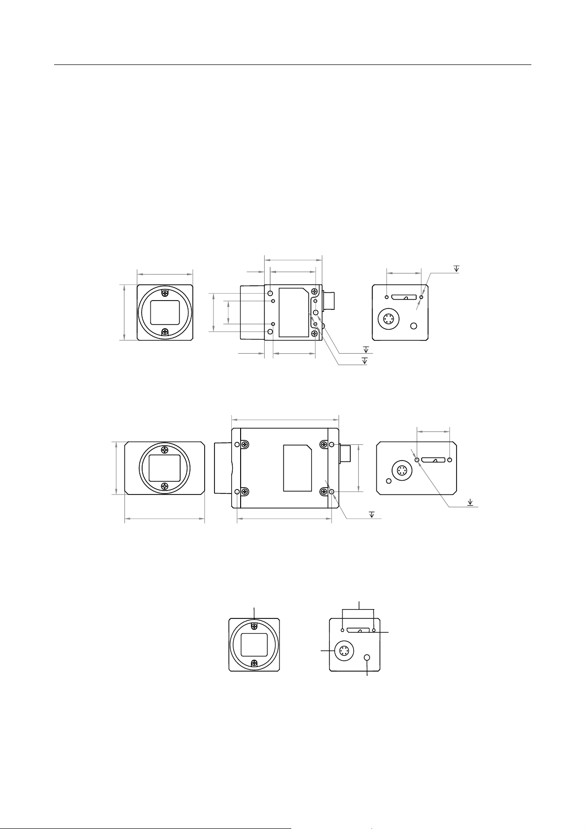
1.1 Appearance
The CA/CE/CH-series USB3.0 area scan camera possesses 2 kinds of appearance, with the same
interface but slight interface position difference, as shown below. Type I and Type II both have a
standard USB interface, a 6-pin power and I/O interface, a LED indicator, and lens mount (C-mount).
You should use M3 or M2 screw to install the camera to a position. These appearances are subject
to change, and the actual device you purchased shall govern.
12
3
3-M3 3
30
18
29
29
20
23.7
22
4.5
4-M2 3
2-M2
3
Unit: mm
Figure 1-1 Appearance (Type I)
44
29
59
26
52
18
4-M3 3.5
2-M2 4
Unit: mm
Figure 1-2 Appearance (Type II)
1
2
3
4
5
Figure 1-3 Interface (Type I)
Page 11
CA/CE/CH-Series USB3.0 Area Scan Camera·User Manual
2
Table 1-1 Interface Description
No.
Description
1
Lens mount (C-mount)
2
M2 screw holes for securing cable
3
Standard USB3.0 interface
4
LED indicator
5
6-pin power and I/O interface
The CA/CE/CH-series USB3.0 area scan camera possesses 2 kinds of appearance, and here we take
type I as an example for interface introduction.
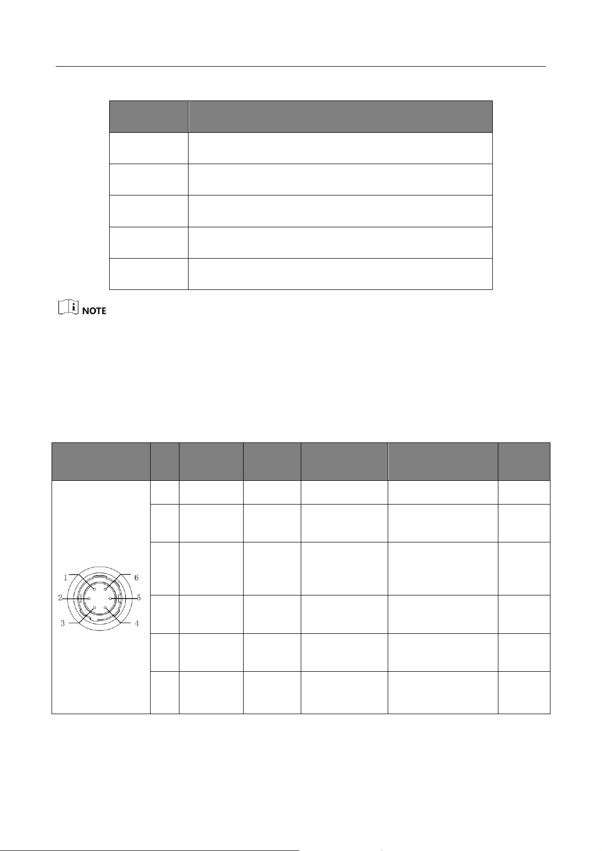
1.2 Power and I/O Interface
The description of the 6-pin power and I/O interface is shown in Table 1-2.
Table 1-2 Description
Illustration
No.
Signal
I/O Type
I/O Signal
Source
Description
Color
1
DC_PWR
--
--
DC Power
Orange
2
Opt-Iso In
Input
Line0 signal
line
Opto-isolated input
Yellow
3
GPIO
Input or
output
Line2 signal
line
Can be configured
either as input or
output
Purple
4
Opt-Iso
Out
Output
Line1 signal
line
Opto-isolated
output
Blue
5
I/O
Ground
--
Line0 and line1
signal ground
Signal ground
Green
6
Gnd
--
Line2 signal
ground
Power ground
Grey
Page 12

CA/CE/CH-Series USB3.0 Area Scan Camera·User Manual
3
The cable color here is subject to change, and the actual cable you purchased shall govern.
1.3 Indicator Description
The indicator has different status, and please refer to the following table for the details.
Table 1-3 Status Definition
Indicator Status
Description
Solid
Indicator keeps solid.
Unlit
Indicator keeps unlit.
Flashing fast
Unlit interval is 0.2 s.
Flashing slowly
Unlit interval is 1 s.
Flashing very slowly
Unlit interval is 2 s.
Table 1-4 Indicator Status Description
Indicator Status
Camera Status
Description
Unlit.
The camera is
powered off.
——
Solid blue.
Camera is in idle
status.
Data cable has connected, and
the camera is ready.
Blue indicator is flashing
slowly.
Internal triggering
acquisition, and U2 is
in transmission status.
Data cable has connected, and
camera is acquiring images
under internal triggering. Data
transmission speed reaches the
rated speed of USB2.0 port.
Blue indicator is flashing
fast.
Internal triggering
acquisition, and U3 is
in transmission status.
Data cable has connected, and
camera is acquiring images
under internal triggering. Data
transmission speed reaches the
rated speed of USB3.0 port.
Page 13

CA/CE/CH-Series USB3.0 Area Scan Camera·User Manual
4
Indicator Status
Camera Status
Description
Blue indicator is flashing
very slowly.
External triggering
acquisition status.
Data cable has connected, and
camera is acquiring images
under external triggering.
Solid red.
Firmware updating
failed or error.
Firmware updating failed, or
configuration file reading failed,
or other device error.
Red indicator is flashing
very slowly.
Connection error.
Data cable is disconnected.
Blue indicator lights up.
Camera’s current
status (Find Me
function).
When executing Find Me
function via client software, the
camera lights up for one time.
Blue and red indicator flash
alternatively with 1 second
duration.
Firmware is updating.
When red LED and blue LED
flash alternatively, firmware is
updating.
Page 14

CA/CE/CH-Series USB3.0 Area Scan Camera·User Manual
5
Chapter 2 Installation
2.1 Install Camera
The CA/CE/CH-series USB3.0 area scan camera possesses 2 kinds of appearance, and here we take
type I as an example for installation.
The camera adopts the USB3.0 interface, and you need to use the USB3.0 cable to guarantee the
bandwidth for real-time image transmission.
Before you start
● The acceptable direct power supply is 5 VDC to 15 VDC. Please make sure your power supply
matches with that of the camera.
● Make sure all the related devices are power-off during the installation.
Steps:
1. Install the lens to the lens mount.
2. Fix the camera to the desired position.
3. Use Micro USB3.0 (type B) cable to connect the camera with the computer or other
transmission devices.
4. Select a power supply method:
● Direct supply: Use the cable with a 6-pin power and I/O interface to connect the camera to a
power adapter.
● USB supply: Use the USB cable to connect the camera to the computer via USB3.0 interface.
Page 15
CA/CE/CH-Series USB3.0 Area Scan Camera·User Manual
6
Chapter 3 Camera Connection
The MVS client is used to connect camera, set its parameters, and etc. This section introduces how
to install the client software and how to connect the camera via the client.
3.1 Install MVS Client
The MVS client software is compatible with 32/64-bit Windows XP/7/10, 32/64-bit Linux, and
64-bit MacOS operating systems. Here we take Windows as an example.
Software version in this manual is V3.1.0. If other versions are used, the graphic user interface
may differ.
You can download the client software installation package from en.hikrobotics.com.
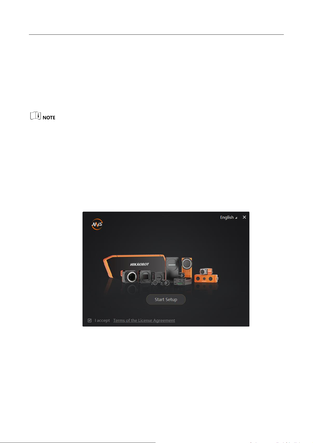
Steps:
1. Double-click MVS installation package to install the client.
2. Read the Terms of the License Agreement and check it.
Figure 3-1 Installation Interface
3. Click Start Setup.
Page 16
CA/CE/CH-Series USB3.0 Area Scan Camera·User Manual
7
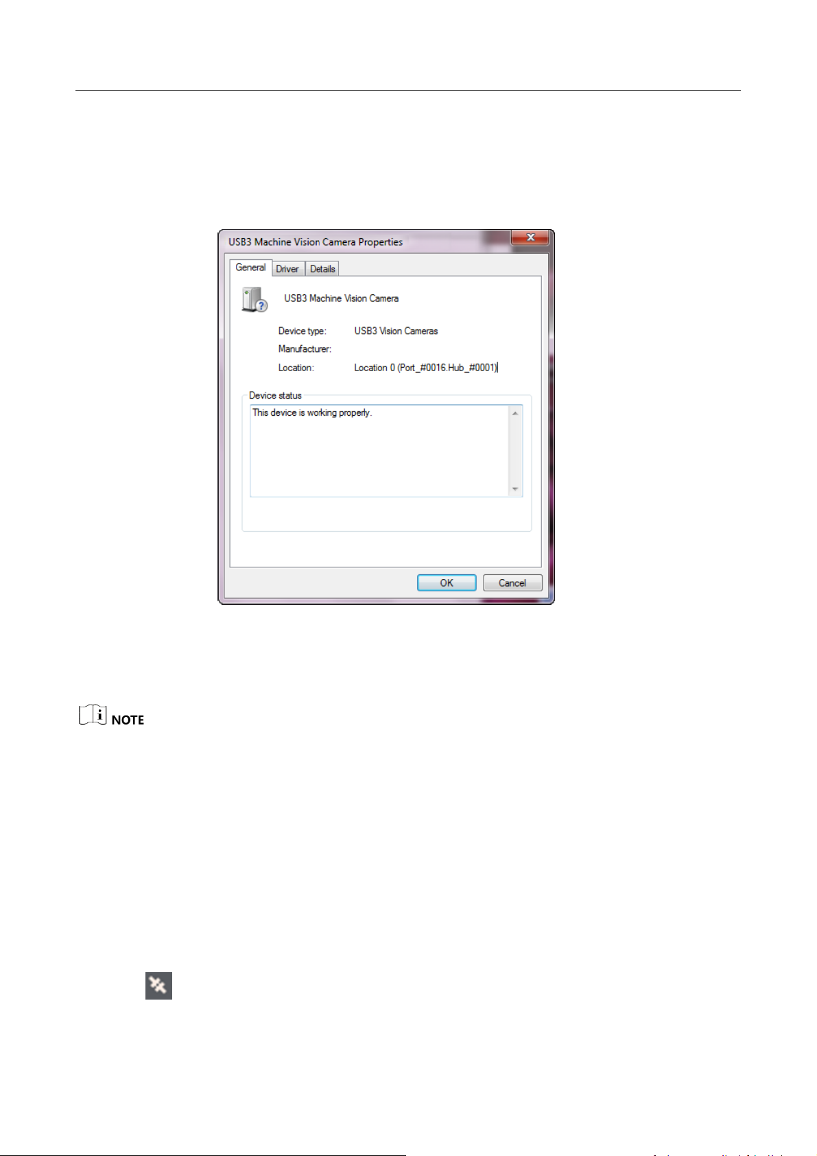
3.2 Check Driver
After connecting the camera, the PC will automatically install USB3 Machine Vision Camera
driver. You can view that camera driver has been successfully installed in the Windows
device manager by right-clicking on camera driver, as shown in Figure 3-2.
Figure 3-2 Driver Properties
If the driver is not successfully installed as shown above, you will need to install it manually.
The driver is at C:\Program Files (x86) \Common Files\MVS\Drivers\USB3.0 by default.
The location of the driver depends on the directory you selected and the computer
operating system you used when installing the client.
3.3 Connect Camera to MVS
Before you start:
Power on the camera.
Steps:
1. Run the MVS client software.
2. Click to link the camera.
Page 17
CA/CE/CH-Series USB3.0 Area Scan Camera·User Manual
8
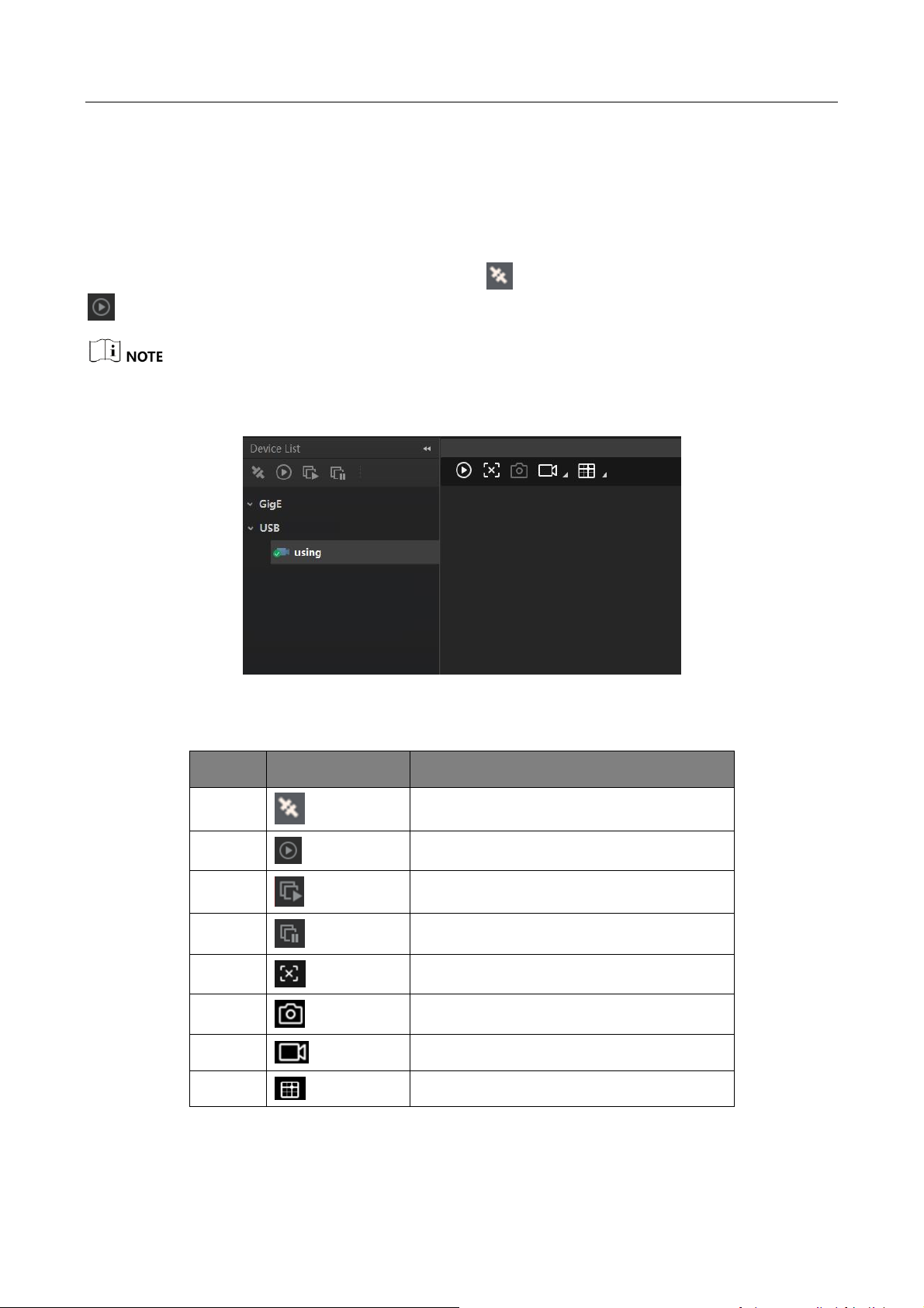
Chapter 4 Live View
If the live view is normal, the camera is connected to the MVS. You can use the camera as you need.
If not, please refer to the former steps and repeat again.
After running the MVS client software, you can click to connect the camera, and then click
to have the live view, as shown below.
Software version in this manual is V3.1.0. If other versions are used, the graphic user interface and
icon may differ.
Figure 4-1 Live View in the MVS
Table 4-1 Icon Description
No.
Icon
Description
1 Connect or disconnect camera.
2 Start or stop acquisition.
3 Start batch acquisition.
4 Stop batch acquisition.
5 Start or stop live view.
6 Capture and save pictures.
7 Start recording.
8 Show cross line.
Page 18
CA/CE/CH-Series USB3.0 Area Scan Camera·User Manual
9
Chapter 5 Camera Settings
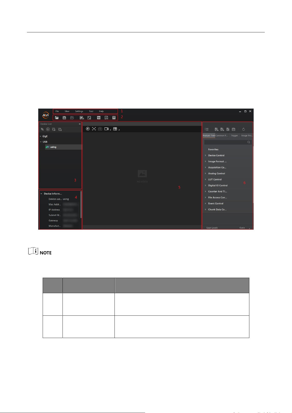
5.1 Main Window
The software can read the XML file of camera attributes and display them in tree format.
Run the MVS client software to enter its main window. The main window and the description of
the client software are shown in Figure 5-1 and Table 5-1.
Figure 5-1 Main Window of the Client Software
For specific main window of the client software, please refer to the actual one you run.
Table 5-1 Description of the Main Window
No.
Area Name
Description
1
Menu Bar
Function modules including File, View, Settings, Tool,
and Help.
2
Control Toolbar
The control toolbar provides quick operations for
camera images.
Page 19

CA/CE/CH-Series USB3.0 Area Scan Camera·User Manual
10
No.
Area Name
Description
3
Device List Panel
Display the GigE Vision cameras, USB3 Vision
cameras, and Camera Link cameras. And provide icons
for connecting/disconnecting camera, start/stop
acquisition, and refreshing device list.
4
Interface and
Device Information
Panel
Display the network interface information and the
device information.
5
Display Window
View the live video of the selected camera.
6
Feature Panel
View and configure features of the selected camera,
and perform other operations such as importing,
exporting, and saving features.
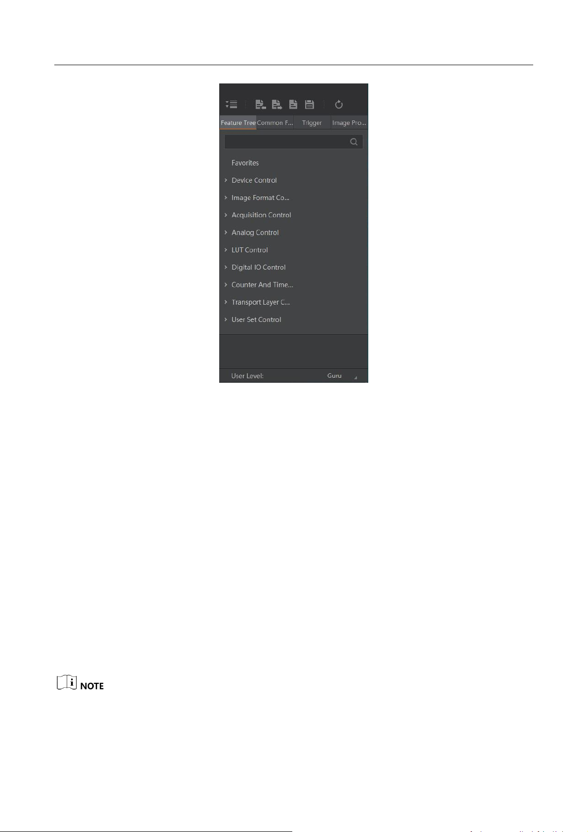
5.2 Set Parameters
The camera setting supports 3 kinds of user level: Beginner, Expert or Guru, which displays
different camera attributes. For Guru Level, it provides the most comprehensive camera attributes
for professional use. Here we take Guru Level as an example.
Page 20
CA/CE/CH-Series USB3.0 Area Scan Camera·User Manual
11
Figure 5-2 Attribute Page
Device Control: You can view the camera details including device type, version, manufacturer
details, device ID, device alias, device temperature, etc. You can reset the device or find the
device.
Image Format Control: You can view the live view image width and height, pixel size, etc. You
can modify the image reverse status, test pattern and the embedded information, etc.
Acquisition Control: You can set the trigger mode, trigger source, exposure details, etc.
Analog Control: You can adjust analog gain, black level, brightness, gamma, sharpness, AOI,
etc.
LUT Control: You can view the user lookup table and set the LUT index and value.
Digital IO Control: You can manage the digital input and output.
Counter and Timer Control: You can set the counter and timer function. It can count the
triggering signal and control the exposure according to the user needs.
Transport Layer Control: You can set the parameters of transport layer of the camera.
Stream Control: You can see the data on data header, effective load, and data tail.
User Set Control: You can save or load the parameter configuration set by users. You can set
the default parameter when running the software.
The specific parameters vary from devices to devices and are subject to the actual ones.
Page 21
CA/CE/CH-Series USB3.0 Area Scan Camera·User Manual
12
Chapter 6 Main Operations
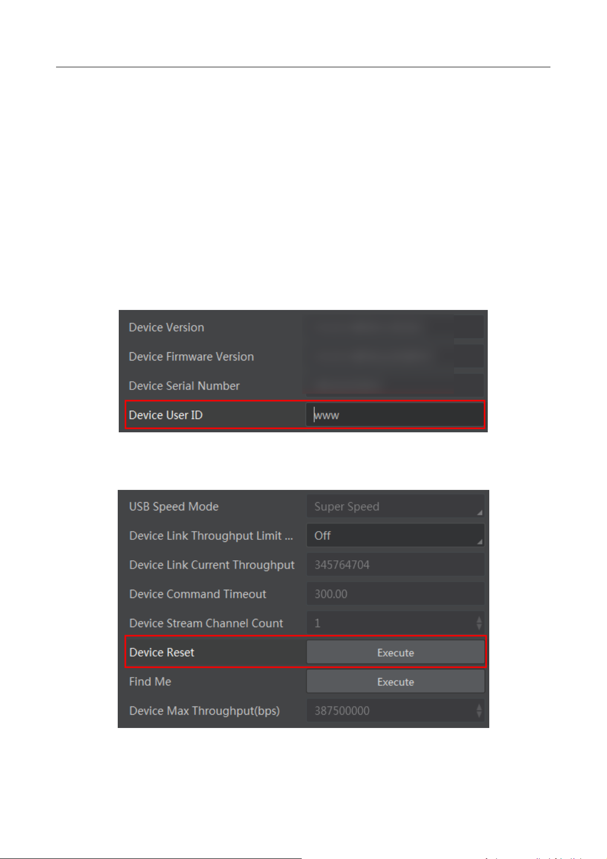
6.1 Device Control
In Device Control interface, you can view device current information, including device version,
firmware version, serial number and ID. You can also input customized device name in the Device
User ID as shown in Figure 6-1.
Steps:
1. Open the client software.
2. Find Device Control and open the list.
3. Input device name in the Device User ID.
Figure 6-1 Edit Device User ID
You can reset the device in Device Control as shown below.
Figure 6-2 Reset Device
Page 22
CA/CE/CH-Series USB3.0 Area Scan Camera·User Manual
13
6.2 Image Format and Frame Rate
The camera supports different image formats and you can set region of interest in the image.
Setting region of interest will increase frame rate.
6.2.1 Set Image Format
The CA/CE/CH-series USB3.0 area scan camera supports many pixel formats. For specific pixel
formats that your camera supports, please refer to the Specifications of the camera which is
available in en.hikrobotics.com.
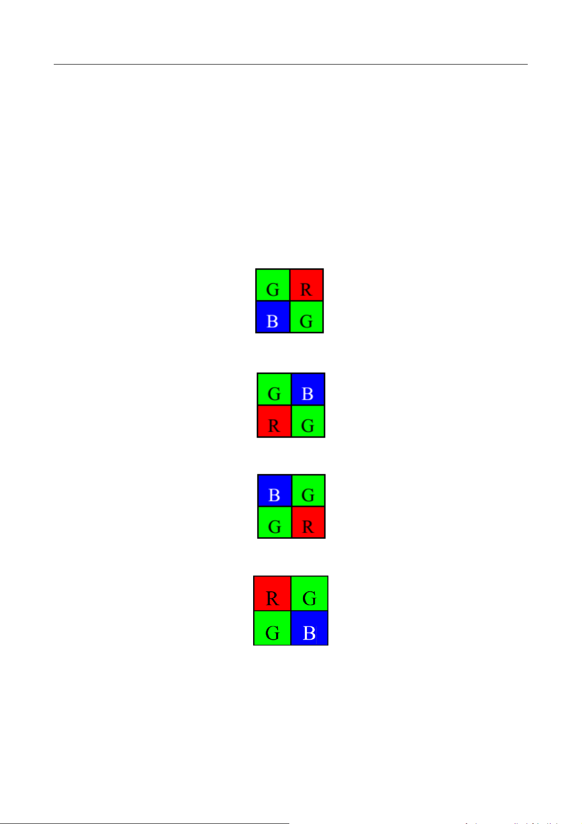
Color camera changes from the original data to RGB8 by color interpolation algorithm. Bayer GR,
Bayer GB, Bayer BG, Bayer RG and other patterns are shown below.
Figure 6-3 Bayer GR Pixel Pattern
Figure 6-4 Bayer GB Pixel Pattern
Figure 6-5 Bayer BG Pixel Pattern
Figure 6-6 Bayer RG Pixel Pattern
To preserve the grayscale feature of the image data, it is done by truncating 8 bits from the upper
bits. The corresponding numbers of bytes to different formats are shown below in Table 6-1.
Page 23

CA/CE/CH-Series USB3.0 Area Scan Camera·User Manual
14
Table 6-1 Byte Number of Different Pixel Formats
Format
Byte Number
Mono8, Bayer GB/GR/BG/RG 8
1
Bayer GR/GB/RG 12 Packed, Bayer BG/GR/RG
10 Packed, Mono10 Packed, Mono12 packed
1.5
Bayer GR/GB/RG 12, Bayer BG/GR/RG 10, YUV
4:2:2 (YUYV), YUV4:2:2 (YUYV) Packed,
Mono10, Mono12
2
RGB 8
3
In client software, you can click Image Format Control > Pixel Format, view the pixel formats that
your camera supports, and select one that satisfies your need as shown below.
Figure 6-7 Set Pixel Format
Pixel format can be set only when you stop real-time acquisition.
6.2.2 Set Frame Rate
The maximum frame rate the camera can achieve depends on the following 3 factors:
Frame Readout: the lower the image height, the shorter the readout time, and thus the higher
the frame rate.
Exposure Time: the shorter the exposure time, the higher the frame rate.
Bandwidth: a wider bandwidth can transport more frames in a given period of time.
Page 24

CA/CE/CH-Series USB3.0 Area Scan Camera·User Manual
15
In client software, you can set a desired acquisition frame rate as shown below.
Steps:
1. Click Acquisition Control -> Acquisition Frame Rate.
2. Input an appropriate acquisition frame rate.
Figure 6-8 Set Frame Rate
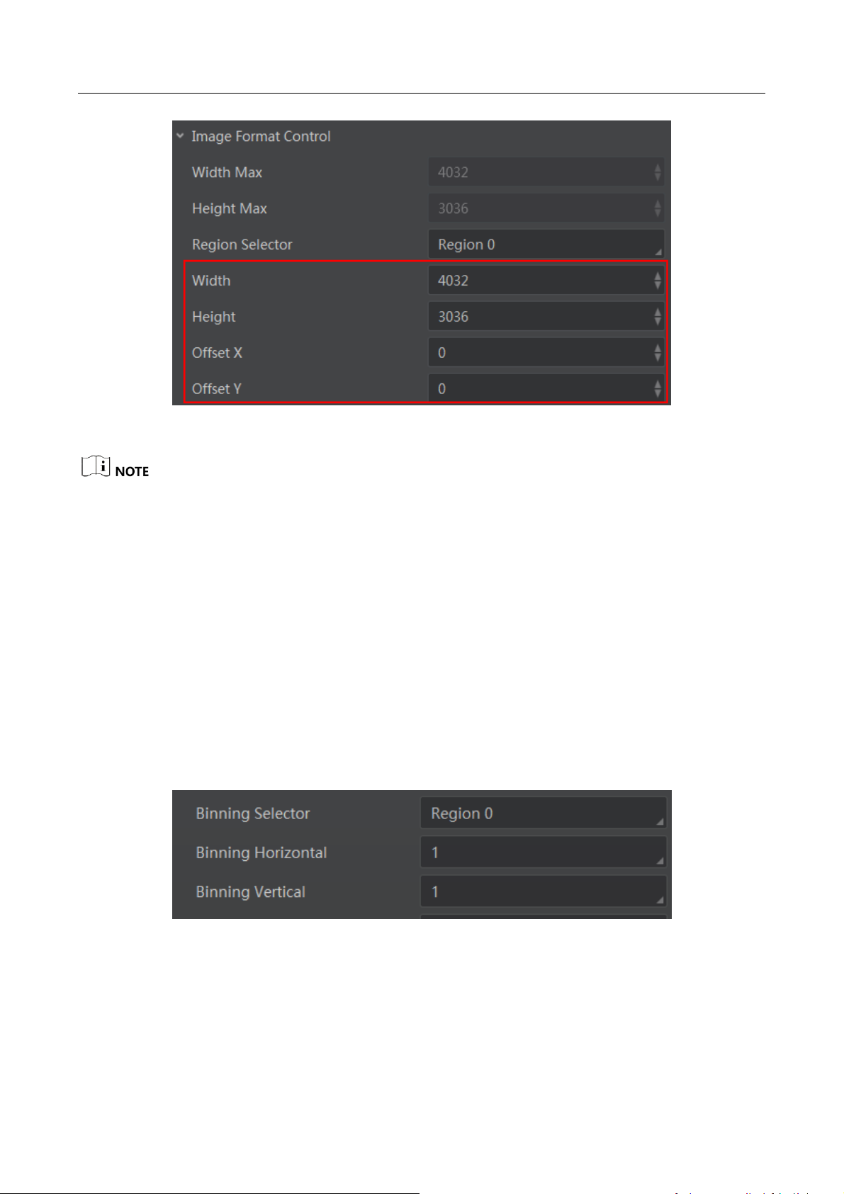
6.2.3 Set Region of Interest
If you are only interested in a certain region of the image, you can set a region of interest (ROI) for
the camera. Setting region of interest can reduce the bandwidth of the image being transmitted,
thus increase the frame rate.
You can set the height and width of the ROI as shown below. Offset X and Offset Y are the
coordinates of the upper left corner of the ROI.
Steps:
1. Click Image Format Control.
2. Set the value in Width and Height.
Page 25
CA/CE/CH-Series USB3.0 Area Scan Camera·User Manual
16
Figure 6-9 Set Region of Interest
Region of interest can be set only when you stop real-time acquisition.
6.2.4 Set Binning
The purpose of setting binning is to enhance sensibility. With binning, multiple sensor pixels are
combined as a single pixel.
Usually, the binning modes used by the camera (vertical and horizontal) are preset and cannot be
changed. However, for specific camera models and for specific binning directions, the binning
mode can be set, as shown below.
Steps:
1. Click Image Format Control.
2. Select value in Binning Horizontal and Binning Vertical.
Figure 6-10 Set Binning
Page 26

CA/CE/CH-Series USB3.0 Area Scan Camera·User Manual
17
6.2.5 Set Decimation
The decimation feature allows you to reduce the number of sensor pixel columns or rows that are
transmitted by the camera. This procedure is also known as "subsampling". It reduces the amount
of data to be transferred and may increase the camera's frame rate.
Steps:
1. Click Image Format Control.
2. Select value in Decimation Horizontal and Decimation Vertical, as shown below.
Figure 6-11 Set Decimation
6.3 Global Shutter and Rolling Shutter
6.3.1 Global Shutter
For cameras that support global shutter: exposure starts and ends in each line simultaneously.
After the exposure, data readout starts line by line. All pixels expose at the same time, then
readout at different time, as shown below.
Line 1
Line 2
Line 3
Line 4
Line 5
Line n
Line n-1
Readout
Readout
Exposure
Figure 6-12 Global Shutter
Page 27

CA/CE/CH-Series USB3.0 Area Scan Camera·User Manual
18
The figure of global shutter’s signal readout under internal trigger mode
Sensor
exposure
Exposure 1 Exposure 2 Exposure 3
Frame 1
Readout
Frame 2
Readout
Figure 6-13 Signal Readout under Internal Trigger Mode
The figure of global shutter’s signal readout under external trigger mode
Trigger_in
1
Sensor
exposure
Exposure
1
Exposure
2
Trigger
delay
Trigger_in 2
Trigger delay
Frame time Frame time
Frame1
Readout
Frame2
Readout
Figure 6-14 Signal Readout under External Trigger Mode
6.3.2 Rolling Shutter
For cameras that support rolling shutter: as soon as the exposure ends, and the data readout starts
simultaneously. After the whole action, the rest of rows start to expose and read out one by one.
All pixels expose at the same time, then readout at different time, as shown below.
Page 28

CA/CE/CH-Series USB3.0 Area Scan Camera·User Manual
19
Line 1
Line 2
Line 3
Line 4
Line 5
Line n
Line n-1
Readout
Readout
Exposure
Offset=Readout
Figure 6-15 Rolling Shutter
The figure of rolling shutter’s signal readout under internal trigger mode is the same with that of
global shutter as shown in Figure 6-13, and the figure of rolling shutter’s signal readout under the
external trigger mode is the same with that of global shutter as shown in Figure 6-14.
6.4 Image Acquisition and Transmission
6.4.1 Set Acquisition Mode
The camera has two image acquisition modes, including continuous mode and single frame mode.
Settings are listed as follows:
Steps:
1. Click Acquisition Control, set the Acquisition Mode as shown below.
2. Select Continuous, the camera output images at current frame rate continuously. Select
SingleFrame, the camera output one single image.
Figure 6-16 Set Acquisition Mode
Page 29

CA/CE/CH-Series USB3.0 Area Scan Camera·User Manual
20
6.4.2 Set Trigger Mode
The camera has two image trigger modes, including internal trigger mode and external trigger
mode. Select On or Off in Trigger Mode to select either external trigger mode or internal trigger
mode. Off refers to the internal trigger mode and On refers to the external trigger mode, as shown
below.
Steps:
1. Click Acquisition Control > Trigger Mode.
2. Select Off or On.
Figure 6-17 Set Trigger Mode
6.4.3 Set External Trigger and Work Mode
The signal for the camera to acquire external trigger includes the software trigger signal and the
signal from external level. Under the external trigger signal mode, the camera can output images
according to single frame acquisition, burst acquisition and other work modes.
The software trigger and hardware trigger of external trigger mode both support related
parameters setting, including trigger delay, trigger cache and etc.
Trigger Delay
From camera receiving signal and responding, this period is trigger delay. It is set by the Trigger
Delay in the client software, and the range is 0 μs to 16000000 μs.
Sensor
exposure
Exposure 1 Exposure 2 Exposure 3
Trigger_in 1
Trigger
delay
Trigger_in 2
Trigger
delay
Trigger_in 3
Trigger
delay
Figure 6-18 Signal Delay Sequence Diagram
Trigger Cache
Page 30

CA/CE/CH-Series USB3.0 Area Scan Camera·User Manual
21
During the triggering process, if the camera receives new trigger signal, it will save and process the
signal. Trigger cache can save up to 2 trigger signals.
Steps:
1. Click Acquisition Control > Trigger Cache Enable.
2. Enable Trigger Cache Enable.
Figure 6-19 Set Trigger Cache
If trigger cache function is disabled, the second trigger signal will be filtered when the first frame is
exposing. If trigger cache function is enabled, the second trigger signal will be saved.
Software Trigger
The camera supports software trigger mode that triggers image acquisition and transmission via
client software.
Steps:
1. Click Acquisition Control > Trigger Mode, select On.
2. Set Software as the trigger source, and click Execute as shown below.
Figure 6-20 Set Software Trigger Mode
Hardware Trigger
Set the trigger source as the line No. of the external hardware to switch to hardware trigger.
Steps:
Page 31

CA/CE/CH-Series USB3.0 Area Scan Camera·User Manual
22
1. Click Acquisition Control > Trigger Mode, select On.
2. Set the line No. (for example Line2) as the trigger source to switch to hardware trigger.
Figure 6-21 Set Hardware Trigger Mode
Trigger Activation
In trigger activation, you can select falling edge or rising edge for external signal.
Steps:
1. Click Acquisition Control > Trigger Activation.
2. Select Falling Edge or Rising Edge, as shown below.
Figure 6-22 Set Trigger Activation
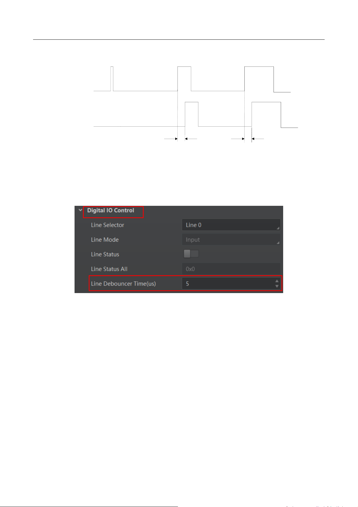
Trigger Debouncer
Signal bouncer may cause false trigger, and it is suggested to debounce the external trigger signal.
You can set debouncer parameter via client, and its sequence diagram is shown below.
Page 32
CA/CE/CH-Series USB3.0 Area Scan Camera·User Manual
23
Trigger_in 1 Trigger_in 2 Trigger_in 3
Trigger_in 2 Trigger_in 3
Before
debounce
After debounce
Debouncer Time Debouncer Time
Figure 6-23 Debouncer of Triggering Input Signal
Steps:
1. Click Digital IO Control > Line Debouncer Time
2. Set value in Line Debouncer Time.
Figure 6-24 Set Debouncer Time
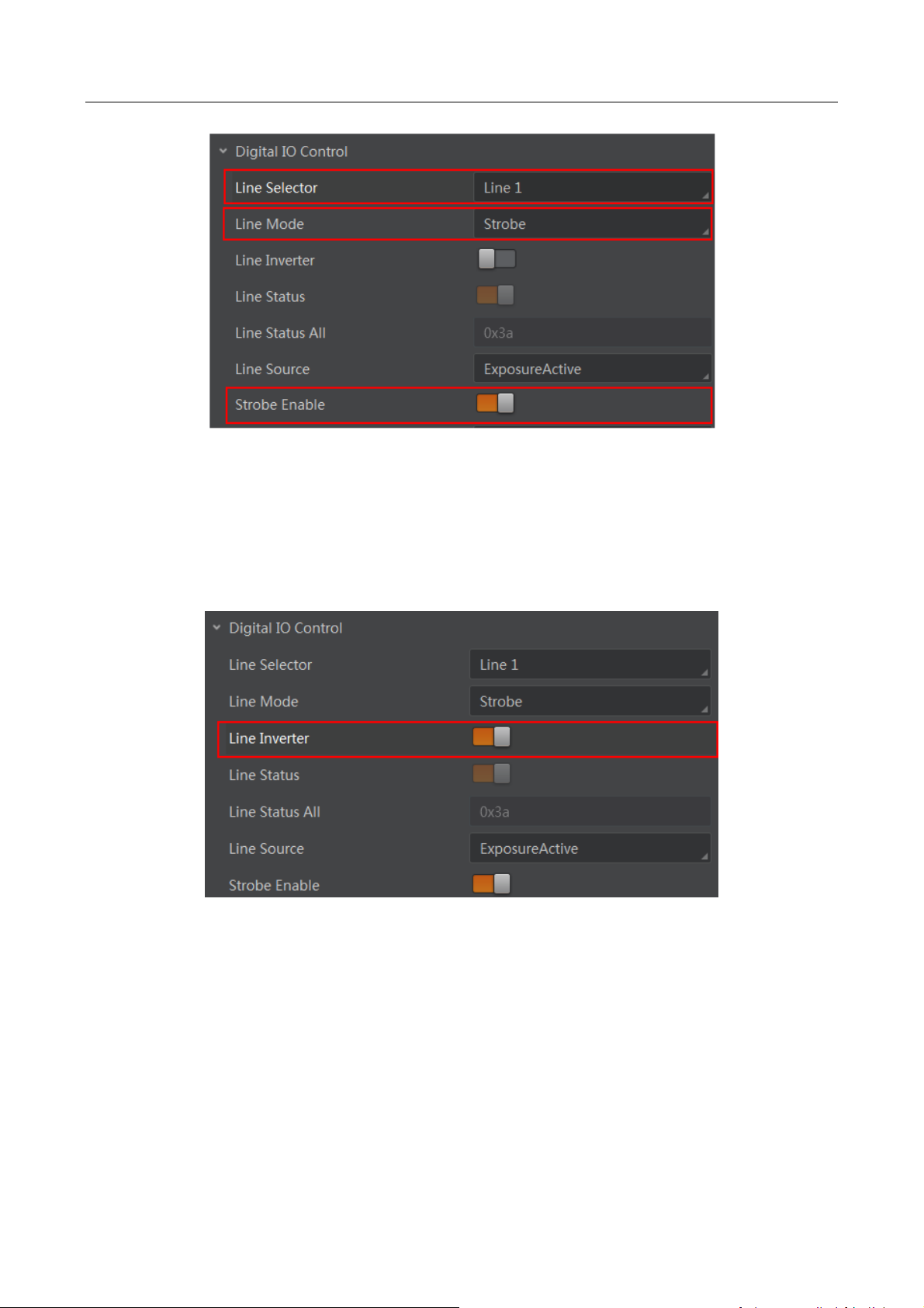
6.5 Set Strobe Output
Strobe is external output signal used to control external devices like flashlight.
Steps:
1. Open the client software, click Digital IO Control > Line Selector, set it as the line No. of
output.
2. Set the Line Mode as Strobe and enable the strobe as shown below.
Page 33
CA/CE/CH-Series USB3.0 Area Scan Camera·User Manual
24
Figure 6-25 Set Strobe Output Mode
You can set the Strobe polarity, duration, output delay and other Strobe parameters through MVS
client software.
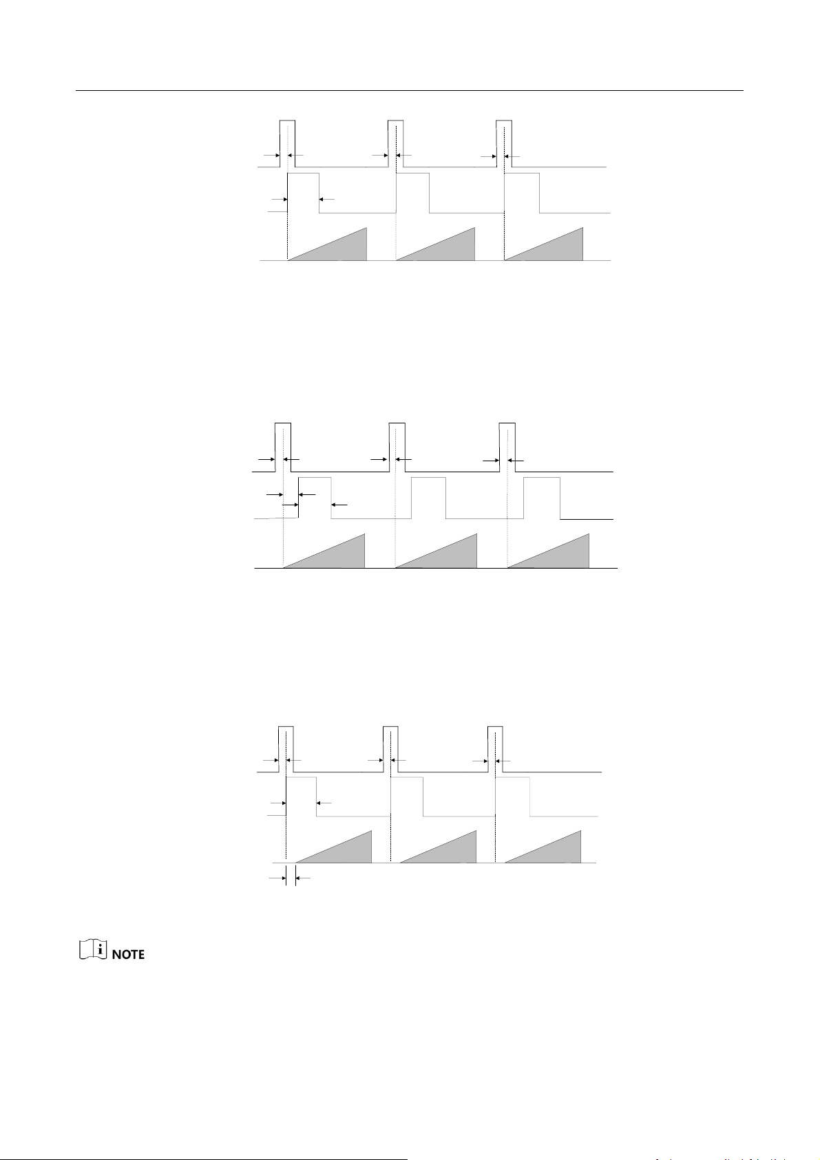
Strobe Polarity
Select Line Inverter to set the external trigger signal polarity as shown below.
Figure 6-26 Set Strobe Polarity
Strobe Duration
Strobe Line Duration value decides the Strobe duration: when the Strobe Line Duration value is 0,
the Strobe duration is equal to the exposure time; when the Strobe Line Duration value is not 0,
the Strobe duration is equal to Strobe Line Duration value.
Page 34
CA/CE/CH-Series USB3.0 Area Scan Camera·User Manual
25
Strobe
Trigger_in 1
Sensor
exposure
Exposure 1 Exposure 2 Exposure 3
Trigger
delay
Trigger_in 2
Trigger
delay
Trigger_in 3
Trigger
delay
Duration
Figure 6-27 Strobe Duration Sequence Diagram
Strobe Output Delay
The camera supports the function of Strobe signal output delay to meet user demands. When
exposure starts, the Strobe output doesn’t take effect immediately. Instead, the Strobe output will
delay according to the setting in Strobe Line Delay.
Strobe
Trigger_in 1
Sensor
exposure
Exposure 1 Exposure 2 Exposure 3
Strobe
delay
Trigger_in 2
Trigger
delay
Trigger_in 3
Trigger
delay
Duration
Trigger
delay
Figure 6-28 Strobe Output Delay Sequence Diagram
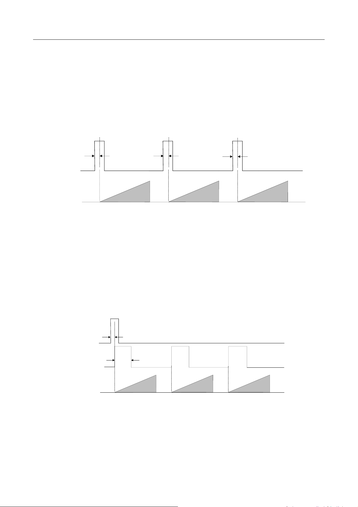
Strobe Pre-Output
The camera also supports the function of Strobe pre-output. This function is applied to the flashing
light that takes time to be stable after starting. It is necessary for a stable light source when
capturing images. You can set pre-output time through Strobe Line Pre Delay in the client.
Strobe
Trigger_in 1
Sensor
exposure
Exposure 1 Exposure 2 Exposure 3
Trigger
delay
Trigger_in 2
Trigger
delay
Trigger_in 3
Trigger
delay
Duration
Strobe pre delay
Figure 6-29 Strobe Pre-Output Sequence Diagram
In fact, the Strobe pre-output function does not output strobe in advance, but delays exposure
instead.
Page 35
CA/CE/CH-Series USB3.0 Area Scan Camera·User Manual
26
6.6 Acquisition Mode under External Trigger
The acquisition mode under external trigger includes single frame mode and burst mode. The
relation among input trigger signal, Strobe output signal, camera exposure time and readout time
under different modes is as follows:
6.6.1 Single Frame Mode
Under this mode, expose once only when inputting one trigger signal.
Sensor
exposure
Exposure 1 Exposure 2 Exposure 3
Trigger_in 1
Trigger
delay
Trigger_in 2
Trigger
delay
Trigger_in 3
Trigger
delay
Figure 6-30 Single Frame Mode Sequence Diagram
During readout time of camera data, triggering the next frame or not depends on frame rate and
exposure time. If exposure is in progress, the camera will ignore another external trigger signal.
Under this mode, you can set a longer exposure time to achieve bulb shutter.
6.6.2 Burst Mode
The camera supports burst mode, which can receive one trigger signal and output multi-frame
images. You can set the burst number by Acquisition Burst Frame Count in the client software, and
the range is from 0 to 1023. If Burst Frame Count = 3, one trigger signal will output three-frame
image. The sequence diagram of burst mode is shown below.
Strobe
Trigger_in 1
Sensor
exposure
Exposure 1 Exposure 2 Exposure 3
Trigger
delay
Duration
Figure 6-31 Burst Mode Sequence Diagram
Page 36

CA/CE/CH-Series USB3.0 Area Scan Camera·User Manual
27
6.7 Non-overlap Exposure and Overlap Exposure
The process that camera captures one frame of image includes two stages, exposure and readout.
According to the overlap relation between the exposure time and the readout time, cameras with
different sensors can be divided into overlap exposure and non-overlap exposure.
6.7.1 Non-overlap Exposure
After completing the current frame’s exposure and readout, the next frame starts to expose and
read out. This process is called non-overlap exposure. The non-overlap exposure’s frame period is
larger than the sum of the exposure time and the readout time, as shown below.
Non-overlap Exposure under Internal Trigger Mode
Sensor
exposure
Exposure 1 Exposure 2 Exposure 3
Frame 1
Readout
Frame 2
Readout
Figure 6-32 Internal Non-overlap Exposure
Non-overlap Exposure under External Trigger Mode
Trigger_in 1
Trigger_in 2 Trigger_in 3
Sensor
exposure
Exposure
1
Exposure
2
Exposure
3
Frame 1
Readout
Frame 2
Readout
Figure 6-33 External Non-overlap Exposure
The camera will ignore the external signal in the readout section under this mode.
6.7.2 Overlap Exposure
Overlap exposure refers to the overlap between the current frame exposure and the previous
frame readout. In other words, when the previous frame starts to read out, the current frame
starts to expose simultaneously, as shown below.
Overlap Exposure under Internal Trigger Mode
Page 37

CA/CE/CH-Series USB3.0 Area Scan Camera·User Manual
28
Sensor
exposure
Exposure 1 Exposure 2 Exposure 3
Frame 1
Readout
Frame 2
Readout
Figure 6-34 Internal Trigger Overlap Exposure
Overlap Exposure under External Trigger Mode
Sensor
exposure
Exposure 1 Exposure 2 Exposure 3
Trigger_in 1 Trigger_in 2 Trigger_in 3
Frame 1
Readout
Frame 2
Readout
Figure 6-35 External Trigger Overlap Exposure
6.8 Counter and Timer Control
Counter provides frequency division to the external trigger signal. Settings are listed as follows:
Steps:
1. Click Acquisition Burst Frame Count > Trigger Source.
2. Set Counter 0 as trigger source.
Figure 6-36 Set Trigger Source
Page 38

CA/CE/CH-Series USB3.0 Area Scan Camera·User Manual
29
3. Select the external signal source under the Counter And Timer Control as shown below.
Figure 6-37 Counter Frequency Division
Line 0 is the signal input by default, and Line 2 can be configured as input or output.
You can conduct frequency division for Line 2 by setting Line 2 as input under Digital IO Control as
shown below.
Figure 6-38 Set Line 2 as Input
4. Set the Counter Value under the Counter And Timer Control as shown below. Its range is from 1
to 1023.
Figure 6-39 Set Counter Value
Page 39
CA/CE/CH-Series USB3.0 Area Scan Camera·User Manual
30
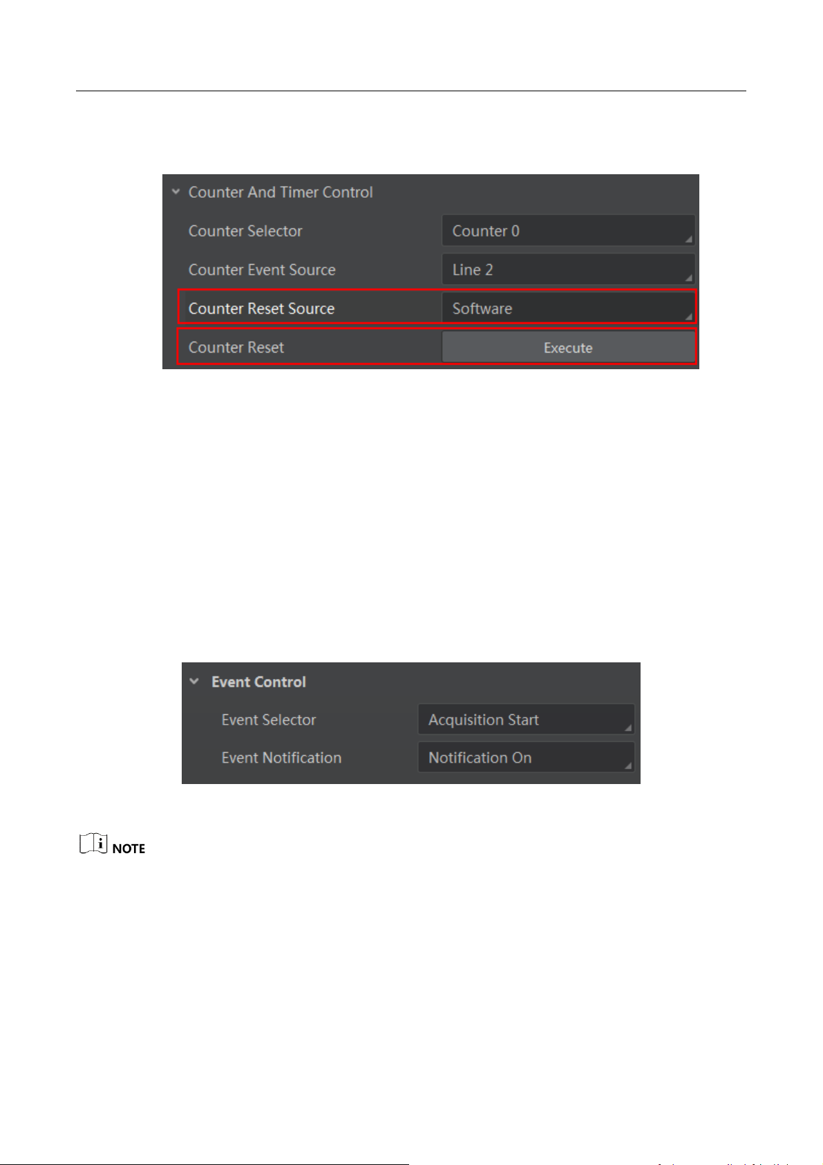
5. By default, Counter Reset Source is Off. You can reset counter by select Software as the Counter
Reset Source, and click Execute to reset as shown below.
Figure 6-40 Reset Counter
6.9 Event Control
When Event Notification is set to Notification On, the camera can generate an event and transmit
a related event message to the computer whenever a specific situation occurs.
Steps:
1. Click Event Control.
2. Select specific situation in Event Selector, for example, Acquisition Start.
3. Set Event Notification as Notification On.
Figure 6-41 Set Event Control
This function should be supported by the device.
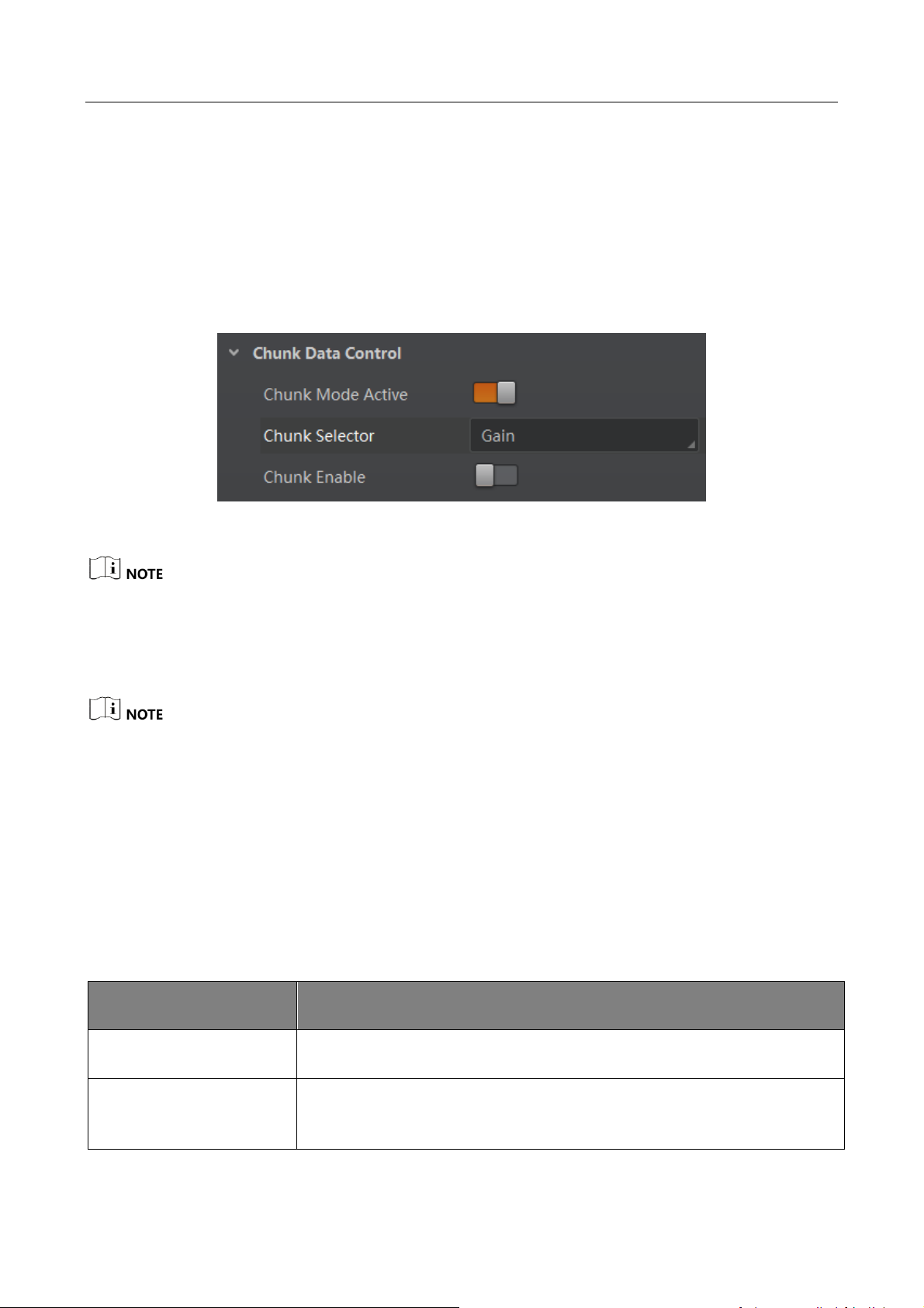
6.10 Chunk Data Control
When Chunk Mode Active is enabled, the camera is in a state where it can generate and append
chunk data to image data and transmit them to the computer. Settings are listed as follows:
Page 40
CA/CE/CH-Series USB3.0 Area Scan Camera·User Manual
31
Steps:
1. Click Chunk Data Control.
2. Enable Chunk Mode Active.
3. Select specific parameters in Chunk Selector.
4. Enable Chunk Enable.
Figure 6-42 Set Chunk Data Control
This function should be supported by the device.
6.11 Image Parameter Setting
Please refer to the Specifications of the camera which is available in en.hikrobotics.com for the
specific parameters.
6.11.1 Set Exposure Time
Exposure is the quantity of light or other radiation reaching a sensor, and it is determined by
shutter speed and lens aperture. The camera supports three types of exposure modes: Off, Once
and Continuous.
Please refer to the following table for details.
Table 6-2 Exposure Mode Description
Mode
Description
Off
The camera does not expose automatically.
Once
Adjust the exposure time automatically according to the image
brightness. After adjusting, it will switch to Off Mode.
Page 41

CA/CE/CH-Series USB3.0 Area Scan Camera·User Manual
32
Mode
Description
Continuous
Adjust the exposure time continuously according to the image
brightness.
Steps:
1. Click Acquisition Control in the attribute list.
2. Select Auto Exposure Time Lower Limit and Auto Exposure Time Upper Limit.
3. Input valid parameter to the numeric field, and then auto exposure time operation parameter
range setting is finished, as shown below.
Figure 6-43 Set Exposure Control
When exposure mode is in Off, you can set Exposure Time by clicking Acquisition Control >
Exposure Time(μs) as shown below.
Figure 6-44 Set Exposure Time
The exposure time you want to set is bounded by the Auto Exposure Time Lower Limit and the
Auto Exposure Time Upper Limit.
6.11.2 Set Gain
Gain is the increasing extent of the electric current, voltage, or power for the component, circuit,
or system. The unit is dB. The larger the gain is, the brighter the image will be.
The camera supports three types of gain control: Off, Once and Continuous.
Table 6-3 Gain Control Description
Mode
Description
Off
Set Gain according to the user’s setting value.
Once
Set Gain value automatically according to the target image brightness.
Page 42

CA/CE/CH-Series USB3.0 Area Scan Camera·User Manual
33
Mode
Description
Set once only.
Continuous
Set Gain value continuously according to the target image brightness.
When setting single mode or continuous mode, Gain is limited by Auto Gain Lower Limit and Auto
Gain Upper Limit. Gain Range should only be set between Auto Gain Lower Limit and Auto Gain
Upper Limit.
Steps:
1. Click Analog Control in the attribute list, click Gain Auto, and then select Gain Mode.
2. Input valid parameter in the numeric field and finish setting, as shown below.
Figure 6-45 Gain Control
Image noise will be amplified when the gain value is increased.
6.11.3 Set White Balance
White balance is the white rendition function of the camera used to adjust the color temperature
according to the environment.
The white balance refers to the camera color adjustment depending on different light sources.
Adjust the Gain Value of the image’s R channel and B channel to keep white regions white under
different color temperatures. Ideally, the proportion of R channel, G channel and B channel in the
white region is 1:1:1.
Page 43

CA/CE/CH-Series USB3.0 Area Scan Camera·User Manual
34
Table 6-4 White Balance Status Description
Status
Description
Off
You need to set the R, G, B value manually, between 1 and 4095. 1024 means
ratio is 1.0
Once
Automatic white balance once. Adjust the white balance for a certain amount
of time then stop. It implements an algorithm that finds possible gray areas
in the Bayer data.
Continuous
Automatic adjust the white balance. It implements an algorithm that finds
possible gray areas in the Bayer data.
White balance is only available on color cameras.
Steps:
1. Click Analog Control in the attribute list.
2. Select Balance White Auto and Balance Ratio Selector.
3. Select the mode and ratio, as shown below.
Figure 6-46 Set White Balance
6.11.4 Set Auto Function AOI
The camera adjusts exposure time and white balance automatically within a certain range to
produce the quality of image you want. By default, the camera adjusts the brightness and white
balance of the entire image.
You can set regional exposure and regional white balance as desired. Regional exposure and
regional white balance is normally used in areas where brightness differs greatly.
Page 44

CA/CE/CH-Series USB3.0 Area Scan Camera·User Manual
35
You can also set an AOI and the camera will adjust the brightness and white balance of the
entire image based on the area you select.
Steps:
1. Click Analog Control, and find Auto Function AOI Selector.
2. Select AOI 1 or AOI 2, and adjust Auto Function AOI Width and Auto Function AOI Height as
shown below.
Figure 6-47 Set AOI
AOI 1 and AOI 2 are associated with shutter and white balance respectively. All cameras have
AOI 1 function, but only color cameras have AOI 2 function.
The effective regional exposure and regional white balance area is where AOI overlaps with
the image. If there is no overlap, the effective area will be the entire image.
6.11.5 Set LUT
A Look-Up Table (LUT) is a customizable grayscale mapping table. You can stretch, amplify the
grayscale range that interests you. The mapping can be linear or customized curve. You need to set
user level to Guru, select LUT Enable true, then set value as shown below.
Figure 6-48 Set LUT
6.11.6 Set Gamma Correction
Generally, the camera sensor’s output linearly relates to the quantity of photons shined upon the
sensor. Gamma correction provides a non-linear mapping mechanism as shown below.
Page 45

CA/CE/CH-Series USB3.0 Area Scan Camera·User Manual
36
Gamma value between 0.5-1: image brightness increases, dark area becomes brighter.
Gamma value between 1-4: image brightness decreases, dark area becomes darker.
1
0.9
0.8
0.7
0.6
0.5
0.4
0.3
0.2
0
1
0.90.80.70.6
0.50.40.3
0.2
0
0.1
0.1
Gamma=1
Gamma=0.5
Gamma=2
Gamma=4
Figure 6-49 Gamma Curve
Steps:
1. Click Analog Control.
2. Find Gamma and Gamma Selector.
3. Set value as shown below.
Figure 6-50 Set Gamma
Different camera versions have different default function parameters. The figures shown above are
only for reference.
Page 46

CA/CE/CH-Series USB3.0 Area Scan Camera·User Manual
37
6.11.7 Set Brightness, Hue and Saturation
Brightness
You can adjust the brightness of the exposure target. The default value is 64. The larger the value,
the brighter the image.
You can set brightness by clicking Analog Control > Brightness, as shown below.
Figure 6-51 Set Brightness
Hue
You can adjust the hue value in HSV. The default value is 128.
Saturation
You can adjust the saturation value in HSV. The default value is 128. The larger the value, the
higher the saturation and the stronger the color.
The brightness function is available when only the camera is in auto exposure mode.
The hue and the saturation are only for the color cameras.
6.11.8 Set Image Reverse
This function is available for the camera that supports image horizontal and vertical reverse.
Steps:
1. Click Image Format Control.
2. Check Reverse X (horizontal) or Reverse Y (vertical) according to your preference, as shown
below.
Page 47

CA/CE/CH-Series USB3.0 Area Scan Camera·User Manual
38
Figure 6-52 Reverse Function
Figure 6-53 ROI Output Area Comparison
Some models support image reverse function, please refer to your camera for actual features.
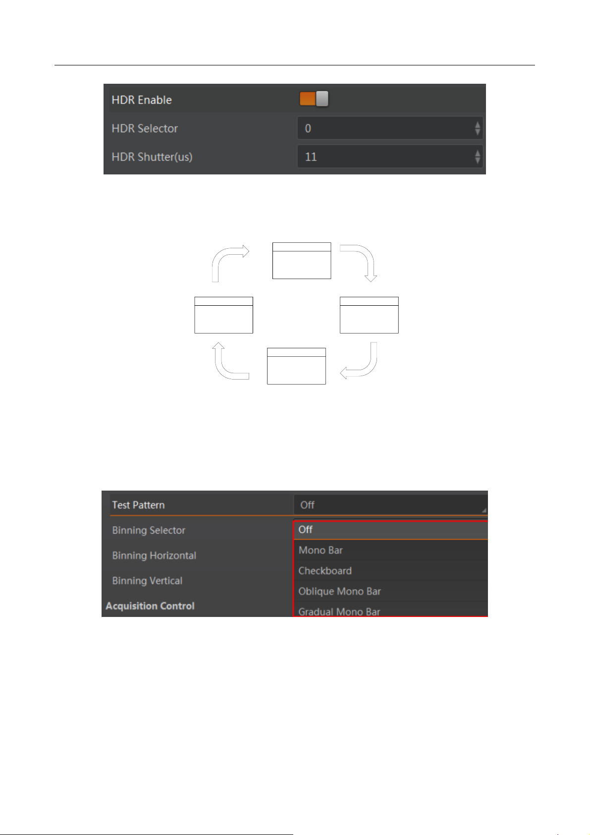
6.11.9 Set HDR Polling
The camera supports HDR polling. In this mode, the camera acquires images based on four
different sets of settings, each with its own exposure time and gain control. In Acquisition Control,
find HDR Selector. Adjust the parameters for each set and then enable HDR Enable as shown
below.
Page 48
CA/CE/CH-Series USB3.0 Area Scan Camera·User Manual
39
Figure 6-54 Set HDR
The polling of the four sets of HDR settings is shown below.
Parameter 0
Exposure Time 0
Gain 0
Parameter 1
Parameter 2
Parameter 3
Exposure Time 1
Gain 1
Exposure 2
Gain 2
Exposure 3
Gain 3
Figure 6-55 HDR Polling
6.11.10 Set Test Mode
In client, click Image Format Control, find Test Pattern and set appropriate parameters. The default
value is Off as shown below.
Figure 6-56 Test Mode
The camera offers six test patterns: Mono Bar, Checkboard, Oblique Mono Bar, Gradual Mono Bar,
Vertical Color Bar and Horizontal Color Bar as shown in Figure 6-57, Figure 6-58, Figure 6-59,
Figure 6-60, Figure 6-61, Figure 6-62.
Page 49

CA/CE/CH-Series USB3.0 Area Scan Camera·User Manual
40
Figure 6-57 Mono Bar Test Pattern
Figure 6-58 Checkboard Test Pattern
Figure 6-59 Oblique Mono Bar Test Pattern
Page 50

CA/CE/CH-Series USB3.0 Area Scan Camera·User Manual
41
Figure 6-60 Gradual Mono Bar Test Pattern
Figure 6-61 Vertical Color Bar Test Pattern
Figure 6-62 Horizontal Color Bar Test Pattern
The test modes that color camera and mono camera support are different, and please refer to your
specific model for actual features.
Page 51

CA/CE/CH-Series USB3.0 Area Scan Camera·User Manual
42
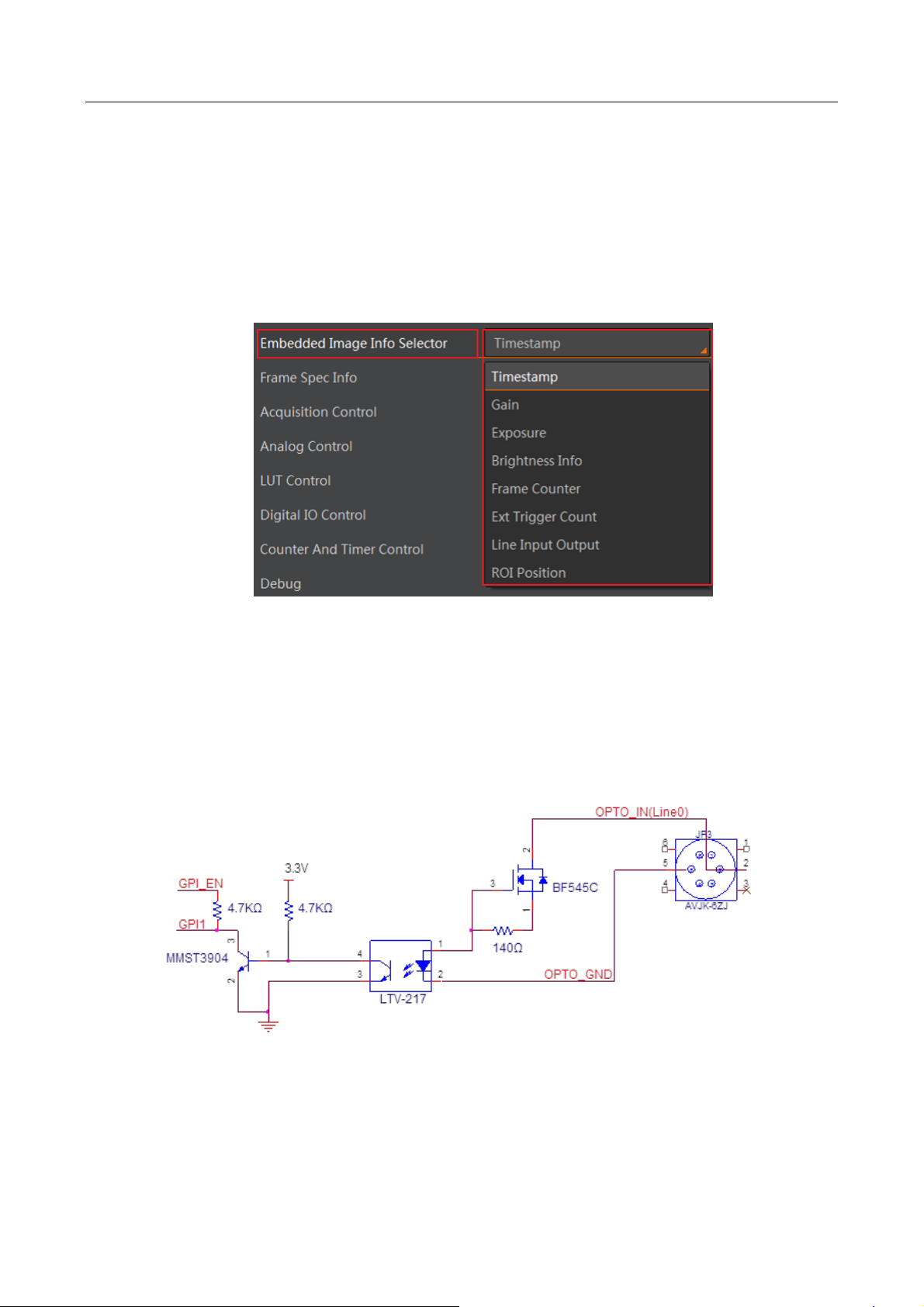
6.11.11 Embedded Information in Image
The camera supports adding and embedding the collection information to the image data. You can
set in the client software and define which information to be embedded in the image data.
Embedded information includes 8 categories: Timestamp, Exposure Time, Frame Number, Alarm
Input/Output, Gain, Brightness, Triggering Number, and ROI.
Each category of embedded information has its unique data format.
Table 6-5 Embedded Information Data Format
No.
Information Type
Byte
Data Format Description
1
Timestamp
4 Bytes
4 bytes are used to transfer the timestamp information.
2
Gain
4 Bytes
4 bytes are used to transfer the gain information.
Each low 8 bits of the 4 valid data are combined to transfer
the gain information.
Value Range: 0 to 1023.
Note: High bits will be complemented with 0 automatically.
3
Exposure Time
4 Bytes
4 bytes are combined to show the exposure time, and the
unit is µs.
4
Brightness
4 Bytes
4 bytes are used to transfer the brightness information.
Value Range: 0 to 4095.
Note: High bits will be complemented with 0 automatically.
5
Frame Number
4 Bytes
Value Range: 0 to 232-1.
6
Trigger Number
4 Bytes
Value Range: 0 to 232-1.
7
ROI
8 Bytes
4 bytes stand for the start point, and 4 bytes stand for the
length and width.
In specific, the column coordinate occupies 2 bytes, and the
row coordinate occupies 2 bytes. The column coordinate
information comes first.
In specific, the length and width occupy 2 bytes
respectively, and the length information comes first.
Page 52
CA/CE/CH-Series USB3.0 Area Scan Camera·User Manual
43
You can set in the client software and define which information to be embedded in the image data.
The camera supports adding the embedded information singularly, or in batch.
Steps:
1. Run MVS client software, and connect to the camera.
2. Click Image Format Control > Embedded Image Info Selector, and select parameters from
drop-down list, as shown below.
Figure 6-63 Embedded Information
6.12 I/O Electrical Feature
6.12.1 Line0 Opto-isolated Input Circuit
Line0 input circuit in camera I/O control is shown below.
Figure 6-64 Input Circuit
Logic 0 input level: 0 VDC to 1 VDC (OPTO_IN pin)
Page 53

CA/CE/CH-Series USB3.0 Area Scan Camera·User Manual
44
Logic 1 input level: 1.5 VDC to 24 VDC (OPTO_IN pin)
Maximum input current: 25 mA
Logic 1
Input Level
Logic 0
Input Level
Internal Logic
TDR TDF
Figure 6-65 Input Logic Level
Input rising delay (TDR): 2.6 μs
Input falling delay (TDF): 19.2 μs
Please make sure the input voltage is not from 1 VDC to 1.5 VDC as the electric status between the
two value is not stable.
6.12.2 Line1 Opto-isolated Output Circuit
Line1 output circuit in camera I/O control is shown below.
1
2345
6
1
2
34
5
6
External Resistor
External Voltage
33Ω PTC
510Ω
GPO
MMST3904
2
1
3
OPTO_OUT(Line1)
OPTO_GND
OPTO_GND
LTV-217
1
2
4
3
100Ω
Figure 6-66 Output Circuit
Maximum Line1 output current: 25 mA
Page 54

CA/CE/CH-Series USB3.0 Area Scan Camera·User Manual
45
Logic 1
Output Level
Logic 0
Output Level
Internal
Logic
TDR TDF TFTR
Figure 6-67 Output Logic Level
Opto-isolated output electric feature is shown in Table 6-6 (the external voltage is 3.3 VDC and the
external resistance is 1 K).
Table 6-6 Output Electric Feature
Parameter
Symbol
Value
Output Logic Low Level
VL
575 mV
Output Logic High Level
VH
3.3 V
Output Rising Time
TR
8.4 μs
Output Falling Time
TF
1.9 μs
Output Rising Delay
TDR
16.6 μs
Output Falling Delay
TDF
3.6 μs
The corresponding current and the parameter of output logic low level when the opto-isolated
outputs the different external voltage and resistance is shown below.
Table 6-7 Parameter of Output Logic Low Level
External Voltage
External Resistance
VL
Output Current
3.3 V
1 KΩ
575 mV
2.7 mA
5 V
1 KΩ
840 mV
4.1 mA
12 V
2.4 KΩ
915 mV
4.6 mA
Page 55
CA/CE/CH-Series USB3.0 Area Scan Camera·User Manual
46
External Voltage
External Resistance
VL
Output Current
24 V
4.7 KΩ
975 mV
4.9 mA
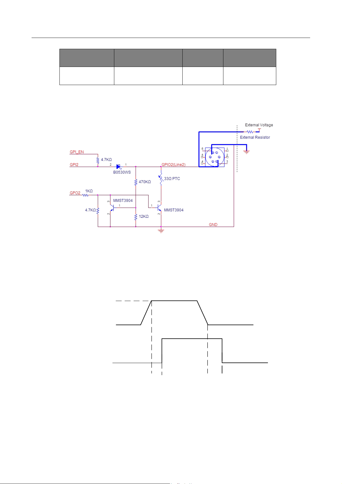
6.12.3 Line2 Configurable Bi-direction I/O Circuit
The configurable bi-direction non-isolated IO circuit of Line2 in camera I/O control is shown below.
Figure 6-68 Bi-direction I/O Circuit
Line2 Configured as Input
Logic 0 input level: 0 VDC to 0.5VDC (GPIO2 pin)
Logic 1 input level: 1.5 VDC to 30 VDC (GPIO2 pin)
Logic 1
Input Level
Logic 0
Input Level
Internal Logic
TDR TDF
Figure 6-69 Input Logic Level
Page 56

CA/CE/CH-Series USB3.0 Area Scan Camera·User Manual
47
Please make sure the input voltage is not from 0.5 VDC to 1.5 VDC as the electric status between
the two values is not stable.
To prevent damage to the GPIO pin, please connect GND first and then input voltage in Line2 pin.
Line2 Configured as Output
The maximum current is 25 mA and the output impedance is 40 Ω.
When the environment temperature is 25 °C (77 °F), the relationship among external voltage,
resistance and the output low level is shown below.
Table 6-8 Parameter of Output Logic Low Level
External Voltage
External Resistance
VL (GPIO2)
3.3 V
1 KΩ
160 mV
5 V
1 KΩ
220 mV
12 V
1 KΩ
460 mV
24 V
1 KΩ
860 mV
30 V
1 KΩ
970 mV
When the voltage of external resistance (1KΩ) is pulled up to 5V, the GPIO2 is configured as output
logical level and the electrical features, as shown below.
Logic 1
Output Level
Logic 0
Output Level
Internal
Logic
TDR TDF TFTR
Figure 6-70 Output Logic Level
Page 57

CA/CE/CH-Series USB3.0 Area Scan Camera·User Manual
48
Table 6-9 Output Electric Feature
Parameter
Symbol
Value
Output Rising Time
TR
0.06 μs
Output Falling Time
TF
0.016 μs
Output Rising Delay
TDR
0.03 μs
Output Falling Delay
TDF
0.28 μs
6.13 I/O Wiring
6.13.1 Line0 Wiring
When the camera uses Line0 as hardware trigger source, wirings are different with different
external devices of input signal.
The camera possesses 2 kinds of appearance, and here we take type I as an example.
PNP Device
Camera Power
Supply
Opt-Iso in
Camera Power
Ground
PWR VCC
Device Power
Supply
Signal Line
Device Power
Ground
PNP Device
I/O Ground
GND of PWR
GND of VCC
Figure 6-71 Line0 Connecting to PNP Device
NPN Device
If the VCC of NPN device is 24 VDC, and it is recommended to use 1 KΩ to 4.7 KΩ pull-up resistor.
If the VCC of NPN device is 12 VDC, and it is recommended to use 1 KΩ pull-up resistor.
Page 58

CA/CE/CH-Series USB3.0 Area Scan Camera·User Manual
49
Camera Power
Supply
Opt-Iso in
Camera
Power Ground
PWR VCC
Device Power
Supply
Signal Line
Device Power
Ground
NPN Device
I/O Ground
GND of PWR
GND of VCC
Figure 6-72 Line0 Connecting to NPN Device
Switch
If the VCC of switch is 24 VDC, and it is recommended to use 1 KΩ to 4.7 KΩ resistor to protect
circuit.
Camera
Power Supply
Opt-Iso in
Camera Power
Ground
PWR VCC
I/O Ground
GND of PWR
GND of VCC
Switch
Figure 6-73 Line0 Connecting to a Switch
6.13.2 Line1 Wiring
When the camera uses Line1 as output signal, wirings are different with different external devices.
PNP Device
Camera
Power Supply
Opt-Iso out
Camera Power
Ground
PWR VCC
Device Power
Supply
Signal Line
Device Power
Ground
PNP Device
I/O Ground
GND of PWR
GND of VCC
Figure 6-74 Line1 Connecting to PNP Device
Page 59

CA/CE/CH-Series USB3.0 Area Scan Camera·User Manual
50
NPN Device
If the VCC of NPN device is 24 VDC, and it is recommended to use 1 KΩ to 4.7 KΩ pull-up resistor.
If the VCC of NPN device is 12 VDC, and it is recommended to use 1 KΩ pull-up resistor.
Camera Power
Supply
Opt-Iso out
Camera Power
Ground
PWR VCC
Device Power
Supply
Signal Line
Device Power
Ground
NPN Device
I/O Ground
GND of PWR
GND of VCC
Figure 6-75 Line1 Connecting to NPN Device
6.13.3 Line2 Wiring
As bi-direction I/O Circuit, Line2 can be used as both input signal and output signal.
Line2 Configured as Input
When the camera uses Line2 as hardware trigger source, wirings are different with different
external devices of input signal.
PNP Device
Camera Power
Supply
Bi-direction
I/O
Camera Power
Ground
PWR VCC
Device Power
Supply
Signal Line
PNP Device
GND of PWR and
VCC
Device Power
Ground
Figure 6-76 Line2 Connecting to PNP Device as Input
NPN Device
If the VCC of NPN device is 24 VDC, and it is recommended to use 1 KΩ to 4.7 KΩ pull-up resistor.
If the VCC of NPN device is 12 VDC, and it is recommended to use 1 KΩ pull-up resistor.
Page 60

CA/CE/CH-Series USB3.0 Area Scan Camera·User Manual
51
Camera Power
Supply
Bi-direction
I/O
Camera
Power Ground
PWR VCC
Device Power
Supply
Signal Line
NPN Device
GND of PWR
and VCC
Device Power
Ground
Figure 6-77 Line2 Connecting to NPN Device as Input
Switch
If the VCC of switch is 24 VDC, and it is recommended to use 1 KΩ to 4.7 KΩ resistor to protect
circuit.
Camera
Power Supply
PWR VCC
Switch
Bi-direction
I/O
Camera Power
Ground
GND of PWR
and VCC
Figure 6-78 Line2 Connecting to a Switch as Input
Line2 Configured as Output
When the camera uses Line2 as output signal, wirings are different with different external devices.
PNP Device
Camera Power
Supply
Bi-direction
I/O
Camera Power
Ground
PWR VCC
Device Power
Supply
Signal Line
PNP Device
GND of PWR
and VCC
Device Power
Ground
Figure 6-79 Line2 Connecting to PNP Device as Output
Page 61

CA/CE/CH-Series USB3.0 Area Scan Camera·User Manual
52
NPN Device
If the VCC of NPN device is 24 VDC, and it is recommended to use 1 KΩ to 4.7 KΩ pull-up resistor.
If the VCC of NPN device is 12 VDC, and it is recommended to use 1 KΩ pull-up resistor.
Camera Power
Supply
Bi-direction
I/O
Camera Power
Ground
PWR VCC
Device Power
Supply
Signal Line
NPN Device
GND of PWR
and VCC
Device Power
Ground
Figure 6-80 Line2 Connecting to NPN Device as Output
6.14 Parameter Set Customization
6.14.1 Save and Load User Set
You can use User Set Control to define camera parameters that you might reuse in camera
operations. The camera supports saving up to 4 sets of parameters: 1 factory set and 3 custom sets,
as shown below. Custom parameter set will take effect after you save it and load it to the camera.
Figure 6-81 User Set Selector
Save the custom parameters set and select it as the default one, otherwise the camera adopts the
factory set every time after being rebooted.
Save Parameters
Steps:
Page 62

CA/CE/CH-Series USB3.0 Area Scan Camera·User Manual
53
1. Click User Set Control, and select a user set in User Set Selector. For example, select User Set
1.
2. Click Execute in User Set Save to save parameters.
Figure 6-82 Select User Set
Figure 6-83 Save User Set
Load Parameters
Steps:
1. Click User Set Control, and select a user set in User Set Selector. For example, select User Set
1.
2. Click Execute in User Set Load to load parameters to the camera, as shown below.
Figure 6-84 Load User Set
Page 63

CA/CE/CH-Series USB3.0 Area Scan Camera·User Manual
54
You can also set default parameter by selecting User Set parameter in User Set Default as shown
below.
Figure 6-85 Set User Default
User Set Current item refers to the current working parameters set.
After you load parameters of the user set into the camera, the value for the User Set Current
item will be changed to the corresponding number.
0 stands for the default factory set, 1 stands for the user set 1, 2 stands for the user set 2, and
3 stands for the user set 3.
The relation among 4 sets of parameters is shown below.
Current
Parameter
User
Parameter 1
User
Parameter 2
User
Parameter 3
Device
Default
Parameter
load
save
load
Figure 6-86 Parameter Relation
Page 64

CA/CE/CH-Series USB3.0 Area Scan Camera·User Manual
55
6.14.2 File Access Control
You can export the feature configuration or DPC (Defective Pixel Correction) of a connected device
to the local PC as a binary file, or import a binary file containing the feature configuration
information or DPC information from the local PC to a connected device.
This function should be supported by the device, and it is not available if you start acquisition.
This function is related with User Set, not the current parameters you set. Setting User Set
Save or User Set Load first if you want to link this function with the current parameters.
Steps:
1. Click or double-click the camera to connect it with the client software.
2. Click to open the File Access window.
Figure 6-87 File Access Window
3. Select a User Set (UserSet1, UserSet2, or UserSet3) or DPC from the drop-down list.
4. Click Export to export the feature to the PC as a binary file.
6.15 Firmware Update
The camera supports firmware update via the MVS client, and you can update the firmware of the
camera via the Firmware Updater.
Before updating, make sure power cable and others are properly connected.
You should stop the live view and disconnect the camera before updating the firmware.
Cameras of different types of interfaces cannot be updated at the same time.
Please use the firmware package of the corresponding camera model for updating.
Steps:
1. Run MVS client software, and click Tool > Firmware Updater to open the update interface.
Page 65

CA/CE/CH-Series USB3.0 Area Scan Camera·User Manual
56
2. Click to select the camera.
3. Click to select the update file in the local PC.
4. Click Upgrade to start updating.
Figure 6-88 Update Firmware
You can only update the firmware when the camera is free, and rebooting is required after
updating the camera.
Page 66

CA/CE/CH-Series USB3.0 Area Scan Camera·User Manual
57
Chapter 7 Trouble Shooting
Table 7-1 Trouble Shooting
No
Trouble
Possible Reason
Solution
1
1. No camera found
when opening the
client.
2. Camera connection
error.
1. Camera is not started
up normally, or USB
cable connection error.
2. MVS client or USB3.0
driver is not normally
installed.
1. Check camera power wiring
(observe the LED indicator), and
check cable connection.
2. Check driver installation.
3. Reinstall MVS client or USB3.0
driver.
2
Live view is black.
Aperture is closed, or
camera error.
Open the aperture or reboot the
camera.
3
Live view is normal,
but camera cannot be
triggered.
Incorrect wiring or
trigger mode is not
enabled.
1. Check whether the camera
trigger mode and related trigger
signal input are normal in the
current environment.
2. Check whether the wiring is
correct under corresponding
triggering mode.
4
Live view and trigger
signal are normal, but
camera can't get the
image required by the
algorithm.
The image output format
does not match.
Confirm the image format required
by the algorithm and adjust the
image output format of the
camera in client software.
5
When live view,
acquiring streams
stops or image
division occurs.
The PC cannot handle
camera data.
1. Set Device Link Throughput
Limit Mode as On in Device
Control.
2. Input value in Device Link
Throughput Limit, and the unit is
byte. The bandwidth of camera in
real-time acquisition cannnot
larger than the value in Device Link
Throughput Limit.
Page 67

CA/CE/CH-Series USB3.0 Area Scan Camera·User Manual
58
Chapter 8 Revision History
Table 8-1 Revision History
No.
Version No.
Document No.
Date
Revision Details
1
1.0.0
UD13016B
Jan. 9, 2019
Original version.
Page 68

UD13016B
 Loading...