

Page 1
日立牌充電式沖擊起子機/扳手
Cordless Impact Driver/Wrench
WH 14DMR • WH 18DMR
WR 14DMR • WR 18DMR
使用說明書
Handling Instructions
WH14DMR WR14DMR
使用前務請詳加閱讀
Read through carefully and understand these instructions before use.
Page 2
1
2
3
6
2
4
9
1
5
3
0
A
B
4
R
8
C
7
L
DD
5
5
4
6
E
3
(B)
2
(A)
1
87
E
F
1
G
Page 3
109
2
E
H
13
11.5mm
3mm
P
K
1211
14
M
O
J
,
.
,.
Q
E
M
I
N
N
L
R
15
16
S
2
Page 4

作業上的一般注意事項
警告﹗使用電池驅動的工具時﹐請務必遵守基本的安
全注意事項﹐以減少發生火災﹑電池泄漏和人身傷害
〔包括以下情況〕的危險在操作本機之前﹐請通讀本說明書﹐並予以妥善保
管-
安全操作注意事項︰
1. 工作場所應打掃乾淨﹐清理妥當﹐雜亂無章將導
致事故-
2. 注意工作地點的環境-請勿讓工具淋雨﹐不可在
潮濕地方使用工具-工作地點要保持明亮請勿在易引起火災或爆炸的場所使用工具-
3. 遠離小孩!請勿讓訪客接觸工具-所有訪客均不
得進入工作地點-
4. 保存好電池和現未使用的工具-未使用工具和電
池時﹐須將它們分開存放在干燥處﹑高處或能上
鎖處﹐以防止小孩取到請確保電池電極不會由螺釘等金屬器件造成短
路-
5. 不得使勁用力推壓-電動工具需按設計條件才能
有效而安全地工作﹐絕不可勉強-
6. 妥選使用工具-不可用小型工具或附件去干重
活-不可將工具用于非指定用途-
7. 工作時衣服穿戴要合適-不要讓松散的衣角和寶
石類卷入轉動部份-屋外作業時﹐最好手戴橡膠
手套﹐腳穿防滑膠鞋-同時要戴上能夠罩籠長髮
的工作帽-
8. 請使用安全眼鏡-如果作業中灰塵多﹐還要戴上
面具或防塵口罩-
9. 連接除塵設備
如果提供連擊除塵和集塵的設備﹐請確認是否已
經連接好並且使用正常-
10. 塞繩不可濫用〔如裝配〕-工具切勿拿著塞繩搬
動或從插座中拔出-不可讓塞繩受熱﹑粘油或碰
到銳利的棱角-
11. 作業以安全第一為原則-工件要用夾具或臺鉗卡
緊-這樣做﹐比用手按壓更為可靠﹐也能夠讓雙
手專心操作-
12. 作業時腳步要站穩﹐身體姿勢要保持平衡-
13. 工具要小心保養-刀具要保持鋒利﹑清潔﹐以確
保性能與安全-請按照潤滑劑和所變更的附件說
明進行-定期檢查工具的電源線﹐發現損壞時請
交由授權的維修中心維修-請保持把手干燥﹑清
潔﹐勿沾上油脂-
14. 斷開工具電源-設計允許時﹐請在工具閑置時﹑
維修前和更換刀片﹑鑽頭和刀具等附件時斷開工
具的電池組-
3
15. 開動前務必把調整用鍵和扳手類拆除下來-這一
點與安全有關-應養成習慣﹐嚴格遵守-
16. 謹防不慎打開開關-搬運鑽機時﹐請勿將手指擱
在開關上-
17. 保持高度警覺﹐充分掌握情況﹐以正常的判斷力
從事作業-疲憊時切不可開動電動工具-
18. 檢查損壞部件-在繼續使用電動工具之前﹐應詳
細檢查各部零件以及防護裝置有無損壞﹐以便判
斷具能否正常工作﹐能否發揮正常效能-檢查轉
動部份的對準﹑空轉﹑各零件有無異常﹐安裝是
否妥善以及其它足以給工作帶來不良影響的情
況如防護以及其它零件損傷了-除非本說明書中已
有記載否則應即委託服務中心進行妥善修理或更
換-請讓授權的服務中心更換有問題的開關-開
關無法打開和關閉工具時請勿使用工具-
19. 警告
使用非本說明書中的推薦的附件可能有發生人身
損害的危險-
確保電池組適用于工具-
在插入充電器之前﹐確保電池組和工具的外表面
清潔干燥-
確保電池由制造商推荐的充電器進行充電-不正
確的使用可能會導致電擊﹑過熱或電池泄漏腐蝕
性液體-
20. 電動工具應請有資格的人員進行維修本工具符合相應的安全要求-只能由有資格的人
員使用原配零件進行維修﹐否則可能會對用戶造
成較大的危險-
21. 電池的使用
確保按照制造商的說明安全使用電池-
22. 如果在錯誤使用時電池流出液體﹐請勿接觸
如果意外發生這種情況﹐請用水沖洗-如果液體
不慎入眼﹐請及時就醫-
充電式衝擊起子機使用上的注
意事項
1. 本工具為手提式工具﹐用於旋緊和旋松螺絲-請
不要用於其它作業-
2. 如長時間進行作業﹐請使用耳塞-
3. 單手操作非常危險-操作時請用雙手握緊電動工
具-
4. 安裝好起子機的鑽頭以後﹐請輕輕地將鑽頭往外
拉確認鑽頭是否松馳-如鑽頭安裝得不妥當﹐在
使用時鑽頭可能會松馳而引起危險-
5. 請使用與螺絲相配的鑽頭-
Page 5

6. 用本衝擊起子機旋緊螺絲時﹐如衝擊起子機與螺
絲之間的位置不成直線﹐則會損壞螺絲頭﹐同時
起子機的旋轉力也不能被妥善地傳給螺絲-所
以﹐旋緊螺絲時﹐請使起子機與螺絲成一直線-
7. 務請在 0∼40°C 的溫度下進行充電- 溫度低於
0°C 將會導致充電過度﹐極其危險-電池不能在
高於 40°C 的溫度下充電-最適合於充電的溫度
是 20∼25°C-
8. 一次充電完成后﹐請將充電器擱置 15 分鐘以
上﹐然后再進行下一次充電請勿連續給兩節以上的電池充電-
9. 勿讓雜質進入充電式電池連結口內-
10. 切勿拆卸充電式電池與充電器-
11. 切勿使充電式電池短路使電池短路將會造成很大的電流和過熱﹐從而燒
壞電池-
12. 請勿將電池丟入火中電池受熱將會爆炸-
13. 請勿將異物插入充電器的通風口若將金屬異物或易燃物插入通風口的話﹐將會引
起觸電事故或使充電器受損-
14. 充電後電池壽命太短不夠使用時﹐請盡快將電池
送往經銷店-請勿將用過的電池亂丟-
15. 請勿使用耗竭了的電池﹐否則會損壞充電器-
充電式沖擊扳手的使用注意事
項
1. 本工具為手提式工具﹐用于旋緊和旋松螺栓和螺
帽-
2. 如長時間進行作業﹐請使用耳塞-
3. 單手操作非常危險-操作時請用雙手握緊電動工
具-
4. 檢查確認套筒沒有破裂破裂的套筒非常危險-使用套筒前請進行檢查-
5. 用套筒銷子和O形環固定套筒如果固定套筒的銷子和O形環受損﹐套筒可能會
從衝擊扳手上脫落﹐這種情況非常危險-如果套
筒的銷子和O形環變形﹑磨損﹑破裂或有其他方
面的損壞﹐請不要使用-請務必將套筒的銷子和
O形環安裝在正確的位置-
6. 檢查旋緊扭矩旋緊螺栓的適當扭矩取決于螺栓的製造材料﹑尺
寸﹑等級等另外﹐本衝擊扳手產生的旋緊扭矩也取決于螺栓
的材料和尺寸﹐以及套筒安裝方式所要求的衝擊
扳手的長度-
另外﹐在電池剛充完電時和電池快用完時﹐扭矩
也略有不同-可使用扭矩扳手來檢查螺栓是否已
按適當的扭矩旋緊-另外﹐在電池剛充完電時和
電池快用完時﹐扭矩也略有不同-可使用扭矩扳
手來檢查螺栓是否已按適當的扭矩旋緊-
7. 在轉換旋轉方向之前先讓衝擊扳手停下來-在轉
換旋轉方向之前﹐務必鬆開開關﹐等衝擊扳手停
下來-
8. 禁止接觸旋轉部位不要讓旋轉的套筒部分靠近手或身體其他部位否則可能會被套筒割傷或卡住-另外﹐在套筒長
時間持續使用之后﹐注意不要碰到套筒-因為套
筒變得很熱﹐可以將人灼傷-
9. 使用萬向接頭時﹐不要讓衝擊扳手空負荷旋轉如果在沒有連接負荷時讓套筒旋轉﹐萬向接頭會
造成套筒劇烈旋轉這樣會造成人身傷害;套筒的劇烈運動還會震動
衝擊扳手以致扳手脫落-
10. 務請在 0∼40°C 的溫度下進行充電-溫度低於
0°C 將會導致充電過度﹐極其危險-電池不能在
高於 40°C 的溫度下充電-最適合於充電的溫度
是 20∼25°C-
11. 一次充電完成后﹐請將充電器擱置15分鐘以上﹐
然后再進行下一次充電請勿連續給兩節以上的電池充電-
12. 勿讓雜質進入充電式電池連結口內-
13. 切勿拆卸充電式電池與充電器-
14. 切勿使充電式電池短路使電池短路將會造成很大的電流和過熱﹐從而燒
壞電池-
15. 請勿將電池丟入火中電池受熱將會爆炸-
16. 請勿將異物插入充電器的通風口若將金屬異物或易燃物插入通風口的話﹐將會引
起觸電事故或使充電器受損-
17. 充電後電池壽命太短不夠使用時﹐請盡快將電池
送往經銷店-請勿將用過的電池亂丟-
18. 請勿使用耗竭了的電池﹐否則會損壞充電器-
4
Page 6
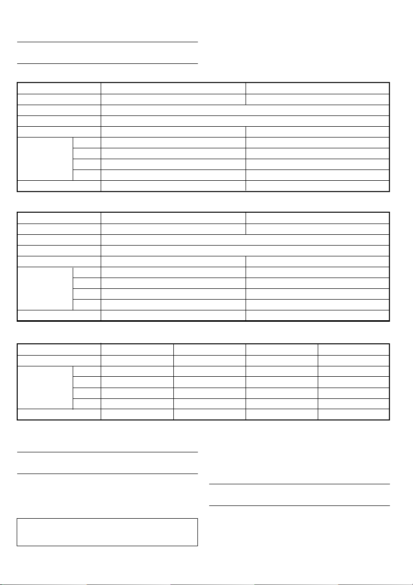
規格
充電式衝擊起子機
型式 WH14DMR WH18DMR
電壓 14.4 V 18 V
無負荷速度 0 - 2600 轉/分
性能(普通螺栓)
旋緊扭矩(最大)
2.0 Ah EB14B: Ni-Cd EB1820L: Ni-Cd
充電電池
重量 1.8 kg 2.0 kg
充電式衝擊扳手機
型式 WR14DMR WR18DMR
電壓 14.4 V 18 V
無負荷速度 0 - 2600 轉/分
性能(普通螺栓)
旋緊扭矩(最大)
充電電池
重量 1.8 kg 2.0 kg
充電器
型式 UC14YFA UC24YFA UC18YG UC18YRL/UC18YFL
充電電壓 7.2 - 14.4 V 7.2 - 24 V 7.2 - 18 V 7.2 - 18 V
充電時間
重量 0.6 kg 0.6 kg 0.3 kg 0.6 kg
所有的充電時間都很接近-實際的充電時間是可以改變的“
×”表示沒有用指定的充電器進行充電-
2.6 Ah EB1426H: Ni-MH EB1826HL: Ni-MH
3.0 Ah EB1430H: Ni-MH EB1830HL: Ni-MH
3.3 Ah EB1433X: Ni-MH EB1833X: Ni-MH
2.0 Ah EB14B: Ni-Cd EB1820L: Ni-Cd
2.6 Ah EB1426H: Ni-MH EB1826HL: Ni-MH
3.0 Ah EB1430H: Ni-MH EB1830HL: Ni-MH
3.3 Ah EB1433X: Ni-MH EB1833X: Ni-MH
2.0 Ah 50 分 50 分 50 分 30 分
2.6 Ah 65 分 65 分 x 40 分
3.0 Ah 70 分 70 分 x 45 分
3.3 Ah 75 分 75 分 x 50 分
140 N.m 150 N.m
200 N.m 220 N.m
M6-M14
M10-M16
電池的拆卸/安裝法
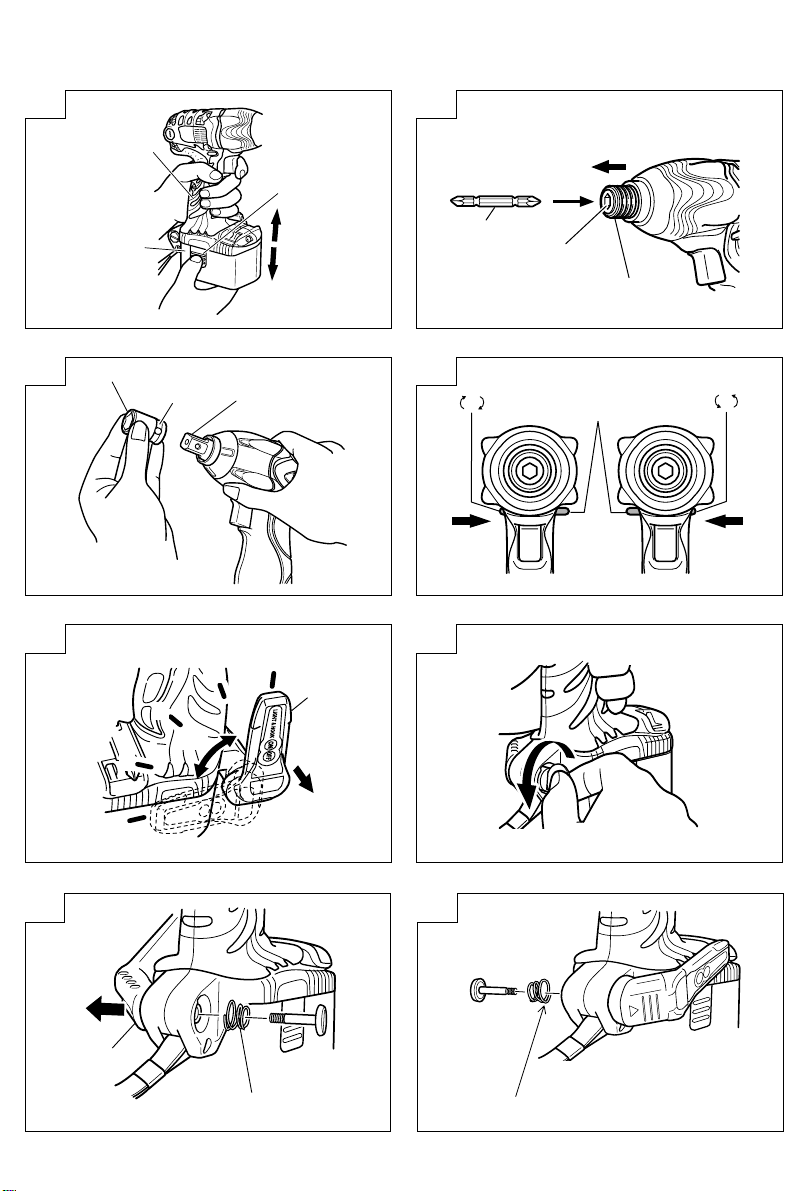
1. 電池的拆卸法
請先緊抓住把手3﹑然後再推壓電池插銷2以拆
下電池1(參照圖 1)-
注意
切勿使電池短路-
5
2. 電池的安裝法
插入電池1時請注意極性(參照圖 1)-
充電
〈UC14YFA, UC24YFA, UC18YRL, UC18YFL〉
使用衝擊起子機/扳手機之前﹐請按照以下方法為電池
充電-
Page 7
1. 將充電器的電源線連接至電源插座
連接電源線時﹐充電器的指示燈將閃爍呈紅色
〔以 1 秒的間隔〕-
2. 將電池裝入充電器
將電池用力插入,直到電池接觸到充電器盒的底
部-
注意﹕
若電池按相反方向插入﹐不僅無法進行充
電﹐而且可能導致如充電器兩端變形等問
題-
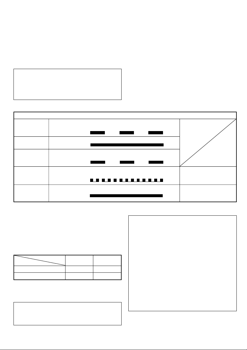
表 1
充電前
充電時
充電完成
無法充電
閃爍
〔紅色〕
點亮
〔紅色〕
閃爍
〔紅色〕
閃動
〔紅色〕
點亮 0.5 秒鐘﹐不點亮 0.5 秒鐘
〔熄滅 0.5 秒鐘〕
連續點亮
點亮 0.5 秒鐘﹐不點亮 0.5 秒鐘
〔熄滅 0.5 秒鐘〕
點亮 0.1 秒鐘﹐不點亮 0.1 秒鐘
〔熄滅 0.1 秒鐘〕
3. 充電
將電池插入充電器后﹐充電開始﹐并且﹐充電器
上的指示燈將持續點亮呈紅色電池完全充電后﹐指示燈將閃爍呈紅色〔以 1 秒的
間隔〕〔參見表 1〕-
(1) 指示燈顯示
根據充電器或充電式電池的情況﹐指示燈的顯示
如表 1 所示-
指示燈的顯示
電池或充電器有問題-
過熱而等待
點亮
〔綠色〕
連續點亮
注:當等待冷卻電池時﹐UC18YRL 通過冷卻風扇使過熱電池冷卻-
(2) 關于充電式電池的溫度
充電式電池的溫度如下表所示﹑在充電前應使已
發熱的電池冷卻片刻-
表 2 電池的充電范圍
充電電池 UC24YFA UC18YFL
鎳鎘電池 -5℃ – 60℃ -5℃ – 55℃
鎳氫電池 0℃ – 45℃ -5℃ – 50℃
充電器 UC14YFA UC18YRL
4. 從電源插座拔下充電器的電源線
5. 握緊充電器并取出電池
注:
注意:
若在電池因長時間放置在受陽光直射的場所或
剛使用后發熱時進行充電﹐充電器的指示燈點
亮呈綠色-在此情況下﹐先將電池冷卻后再開
始充電-
指示燈閃動呈紅色時〔以 0.2 秒鐘的間隔〕﹐
請檢查并取出充電器電池安裝孔內的任何異
物- 若無異物﹐則可能電池或充電器發生故
障-請帶去經授權的維修中心檢查-
因內置的微機需要約 3 秒鐘才能確認正用
UC14YFA﹑UC24YFA﹑UC18YRL 和 UC18YFL
進行充電的電池已被取出﹐因此請待 3 秒鐘后
再重新插入電池繼續充電充電完成后﹐請先從充電器內取出電池﹐然后加以
妥善保存-
〈UC18YG〉
使用衝擊起子機/扳手機之前﹐請按照以下方法為電池
充電-
電池過熱-無法充電(電池
冷卻后開始進行充電)-
6
Page 8

1. 將充電器的電源線插頭插入插座
接好電源線后便開始充電-
2. 將電池插入充電器
按正確的電極方向插入電池直至其接觸到充電器
底部(此時指示燈亮起)-
注意
如果指示燈不亮﹐則請從插座上拔出電源線插頭並
檢查電池的安裝情況-
在約 20℃的溫度下約需 60分便可完全充電-指示
燈熄滅表示電池已經充好如果溫度或電源電壓偏低﹐電池充電時間則會延
長如果充電已超過超過120分而指示燈仍不熄滅﹐則
應停止充電並與您的日立授權維修中心聯繫-
注意
作業停止后﹐如電池(因晒太陽等原因)而變
熱﹐充電指示燈會不亮-這時﹐應先讓電池冷
卻﹐然后再充電-
3. 將充電器電線從插頭拔下
4. 抓穩充電器並取出電池
關于使用新電池等情況下的放電-
由于新電池和未經長期使用的電池的內部化學物
質沒有活性﹐在前一兩次使用時放電量會較低這只是暫時現象﹐通過2至3次充電后﹐將會恢
復充電所需正常時間-
怎樣讓電池使用時間更長-
(1) 在電池電量完全耗盡之前給電池充電-
在感覺工具的動力變弱時﹐停止使用工具並為電
池充電如果繼續使用工具消耗電流﹐可能會造成對電池
的損壞﹐電池使用壽命會縮短-
(2) 避免在高溫下充電-
充電電池在剛使用后會發熱-如果在電池剛使用
后為電池充電﹐電池的內部化學物質的性能會下
降﹐電池使用壽命會縮短- 請先將電池放置一
會﹐待電池冷卻后再進行充電-
作 業 之 前
1. 工作環境的準備和檢查
請確認工作環境確實附加注意事項中所規定的所
有條件-
2. 電池的檢查
請確認電池是否裝緊了-如電池稍有松馳﹐則電
池可能會掉出來而引起事故-
3. 鑽頭的安裝(衝擊起子機)
請務必要按照下列順序安裝起子機的鑽頭
(圖 2)(1) 向后拉出導套7-
(2) 將鑽頭9插入鐵砧8中的六角孔-
(3) 松開﹐導套7便會回到其原來位置-
注意:
如導筒不回到其原來位置﹐則說明鑽頭沒有安裝
好-
4. 選擇與螺栓匹配的套筒(衝擊扳手機)
請務必使用與要旋緊的螺栓相匹配的套筒-使用
不合適的套筒不僅無法充分旋緊螺栓﹐而且會損
壞套筒或螺母-
磨損或變形的六角形或方形套筒沒有足夠的緊密
性與螺母或砧座吻合﹐因此會造成旋緊扭矩的降
低-
請注意套筒孔的磨損﹐在進一步磨損產生之前進
行更換-
5. 安裝套筒(衝擊扳手機)
選擇要使用的套筒-
● 銷子﹑O形環的類型
(1) 將套筒的孔與砧座的孔對準並將砧座插入套筒(2) 將銷子插入套筒(3) 將O形環套到套筒的凹槽上-
● 柱塞式(圖3)
將砧座B方形部分上的柱塞與六角形套筒0的孔
對準-然后推動柱塞﹐將六角形套筒0安裝到砧
座B上-檢查柱塞是否與套筒完全吻合- 要卸下
套筒0時﹐按相反的順序操作-
● 扣環類型
(1) 對齊套筒與砧座的四方形部分(2) 將套筒推至砧座底部﹐使其安裝牢固(3) 將套筒拔出砧座即可拆下套筒-
7
Page 9

注意
請使用操作手冊或日立牌產品目錄中列出的指
定附件若不使用指定附件可能導致意外或傷害-
請將套筒牢固安裝在砧座上﹐否則套筒可能飛
出﹐造成傷害-
使 用 方 法
注意
使用裝有標燈的掛鉤時﹐千萬注意不要讓主要
設備掉落-如果工具掉落﹐則有發生事故的危
險-
在用腰帶上懸掛的裝有標燈的掛鉤攜帶工具主
體時﹐請不要在工具主體上裝配除菲利浦刀頭
以外的尖頭工具-如果在腰帶上懸掛帶有尖頭
部件(如鑽頭)的設備﹐可能會造成傷害-
1. 使用輕便掛鉤
可將輕便掛鉤安裝在左側或右側﹐并可在0度和80
度之間分5級調節角度-
(1) 操作掛鉤
(a) 按箭頭方向(A)朝身邊拉出掛鉤E﹐並按箭
頭方向(B)轉動-(圖 5)
(b) 可分 5 級調節角度(0°﹐20°﹐40°﹐60°﹐
80°)-
請將掛鉤調節到操作所需的位置-
(2) 切換掛鉤位置-
注意:
不完整地安裝掛鉤可能會在使用時導致傷害-
(a) 緊緊抓住主機並用槽頭螺絲刀或硬幣取下螺
釘-(圖 6)
(b) 取下掛鉤E和彈簧F-(圖 7)
(c) 將掛鉤E和彈簧F安裝在另一側並用螺釘固
定-(圖 8)
注:
請注意彈簧F的方向-請按較大直徑G朝外的方向
安裝彈簧F-(圖 8)
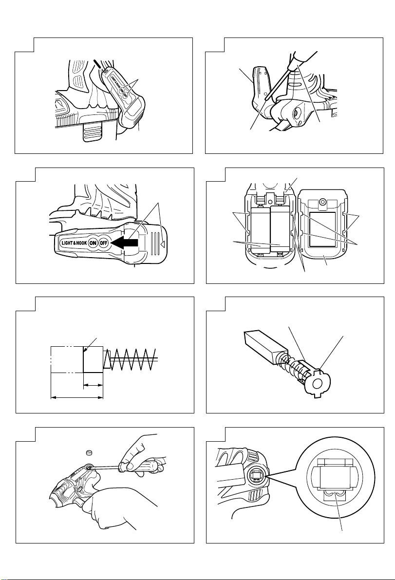
(b) 可在掛鉤位置1-5 範圍內調整照明方向(圖
9)-
照明時間
AAAA錳電池:大約15小時
AAAA鹼性電池:大約30小時
注意
切勿直視輔助燈﹐
否則會傷害眼睛-
(4) 更換電池
(a) 使用十字螺絲起子(1號)鬆開掛鉤螺釘J
(圖10)按照箭頭方向推開掛鉤蓋L(圖11)-
(b) 取出舊電池﹐裝入新電池-根據掛鉤指示正確
安放正極(+)與負極(-)(圖12)-
(c) 將掛鉤E主體上的缺口與掛鉤蓋L上的凸起對
齊﹐依圖11中的箭頭K相反的方向按下掛鉤
蓋L﹐並旋緊螺釘使用市售AAAA電池(1.5V)O-
註
切勿過度旋緊螺釘﹐否則會損壞螺釘的螺紋-
注意
不遵守以下事項會導致電池洩漏﹑生鏽或發生
故障正確放置電池正極(+)與負極(-)一次更換兩節電池﹐切勿混合使用新舊電池即時取出耗盡的電池-
切勿將電池與一般垃圾一起丟棄﹐切勿將電池
放入火中-
將電池放在兒童不能觸及的地方-
根據電池規格與說明正確使用電池-
2. 檢查旋轉方向
按下按鈕C的 R 側﹐鑽頭便以順時針方向(從背
面觀看時)旋轉按下按鈕的 L 側﹐鑽頭則以你時針方向旋轉(請參照圖 14)(機身上有 L L 和 R R 標誌)
注意
在衝擊起子機運轉期間﹐無法切換按鈕-要切換按
鈕時﹐先停止衝擊起子機運轉﹐然后再設定按鈕-
(3) 使用輔助燈
(a) 按下開關H可關閉燈-如果忘記關燈﹐15分鐘
后燈會自動熄滅-
3. 開關操作
按啟動開關時﹐電動工具開始轉動-鬆開啟動開
關﹐電動工具則停止轉動-
8
Page 10

可通過改變拉動啟動開關的量來控制其轉速-輕
拉啟動開關﹐轉速較低;用力拉動﹐則轉速加
快-
4. 螺絲的旋緊和旋鬆(衝擊起子機)
請安裝與螺絲相配的鑽頭-請先將鑽頭插進螺絲
頭的槽中﹐然後再旋緊螺絲請勿用過大的力按住衝擊起子機﹐只要不使鑽頭
不離開螺絲頭即可-
注意:
衝擊時間過長時﹐會將螺絲旋得太緊以致會損壞螺
絲和鑽頭尖用本衝擊起子機旋緊螺絲時﹐如衝擊起子機與螺絲
之間的位置不成直線﹐則會損壞螺絲頭﹐同時起子
機的旋轉力也不能被妥善地傳給螺絲-所以﹐旋緊
螺絲時﹐請使起子機與螺絲成一直線-
操作上的注意事項
1. 連續作業后須讓電動工具休息片刻
在連續進行螺栓緊固作業后以及在更換電池后﹐
請讓電動工具暫停作業 15 分鐘-如果在更換電池
后立刻開始作業﹐馬達和開關等的溫度將會升
高﹐結果導致燒毀-
注:
請不要接觸錘套﹐因為經過持續工作後錘套變
得很熱-
2. 關于轉速控制開關的注意事項
此開關帶有可無級改變轉速的內置電路-因此﹐
當輕拉啟動開關(低速轉動)並在連續旋緊螺絲
中停止馬達轉動時﹐電路部分的元件可能會因過
熱而損壞-
3. 使用適宜於螺絲的旋緊時間
根據螺絲的材料和尺寸以及所旋緊的材料等﹐其
適宜的轉矩有所不同﹐因此請使用適宜于該螺絲
的旋緊時間-尤其是﹐如果對小于 M8 的螺絲使用
過長的旋緊時間﹐則螺絲有損壞的危險- 因此﹐
請事先確認旋緊時間和旋緊轉矩-
4. 以適于受衝擊螺栓的旋緊扭矩進行操作
螺栓和螺母最適宜的旋緊扭矩因螺栓或螺母的材
料和尺寸而有所不同-對小螺栓使用過大的旋緊
扭矩會扭曲或損壞螺栓-旋緊扭矩的增加與操作
時間成正比-請使用正確的螺栓操作時間-
5. 把持工具
用雙手抓穩工具-在這種情況下抓住扳手對準螺
栓-沒有必要非常用力地推送扳手-抓住扳手﹐
只要讓力量足以抵消衝擊力即可-
6. 確定旋緊扭矩
下列因素會造成旋緊扭矩的下降-因此請在工作
前用手工扭矩扳手來確定上緊螺栓所需的實際旋
緊扭矩-影響旋緊扭矩的因素如下-
(1) 電壓
達到放電極限時﹐電壓降低﹐旋緊扭矩也減少-
(2) 操作時間
操作時間增加時旋緊扭矩也增加-但是﹐即使工
具驅動很長的一段時間﹐旋緊扭矩也不會增大到
超過某個特定值-
(3) 螺栓的直徑
旋緊扭矩根據螺栓的直徑變化-一般來說較大直
徑的螺栓需要較大的旋緊扭矩-
(4) 旋緊的狀態
即使使用相同尺寸螺紋的螺栓﹐旋緊扭矩根據螺
栓的扭矩比率﹑等級和長度也各不相同-旋緊扭
矩還因螺栓所要上緊的加工件的表面狀況而有所
不同- 螺栓和螺母一起轉動時﹐扭矩會大大減
少-
(5) 使用可選配件(衝擊扳手機)
使用接長杆﹑萬向接頭或長套筒時﹐旋緊扭矩會
略有減少-
(6) 套筒的間隙(衝擊扳手機)
磨損或變形的六角形或方形孔套筒無法與螺母或
砧座充分吻合﹐因此會造成旋緊扭矩的降低使用與螺栓不匹配的不合適套筒會造成扭矩不
足-
維 護 和 檢 查
1. 檢查起子機的鑽頭(衝擊起子機)
繼續使用已破損的鑽頭或鑽頭尖已磨損的鑽頭是
非常危險的﹐因為鑽頭會滑脫-因此﹐請更換已
破損的鑽頭或鑽頭尖已磨損的鑽頭-
2. 檢查套筒(衝擊扳手機)
磨損或變形的六角形或方形孔套筒無法與螺母或
砧座充分吻合﹐因此會造成旋緊扭矩的降低-請
9
Page 11

注意定期檢查套筒孔的磨損狀況﹐如有必要請更
換新套筒-
3. 檢查安裝螺釘
要經常檢查安裝螺釘是否緊固妥善-若發現螺釘
鬆了﹐應立即重新扭緊﹐否則會導致嚴重的事
故-
4. 馬達維護
馬達線圈是電動工具的「心臟」注意不要損壞線圈及/或不要使線圈沾上油或水-
5. 檢查碳刷(圖13)
馬達中使用碳刷﹐碳刷是消耗零件-碳刷過度磨
損會導致馬達故障﹐所以碳刷磨損或接近“磨損
極限P ”時要立即更換- 另外﹐要保持碳刷清
潔﹐並保證其能在碳刷支架內自由滑動-
注意
更換碳刷時務必使用日立牌碳刷(代碼號碼
999054)-
6. 更換碳刷
首先卸下刷蓋﹐然後使用槽頭螺絲起子等勾住碳
刷的凸起R﹐將碳刷取出﹐如圖15所示安裝碳刷時﹐調整碳刷方向﹐使碳刷刷爪Q對準
刷管外部的接觸凸起S-然後將碳刷推入﹐如圖
16所示-最後安裝刷蓋-
注意
一定要將碳刷刷爪插入刷管外部的接觸凸起-(可
插入兩個刷爪中的任何一個-)
一定要小心執行此步驟﹐任何錯誤都會導致碳刷刷
爪變形﹐並可能造成馬達提早出現故障-
7. 清理外部
衝擊起子和衝擊扳手沾汙時﹐用乾軟布或沾肥皂
水的布擦拭-切勿使用氯溶液﹑汽油或稀釋劑﹐
以免塑膠部分溶化-
8. 收藏
衝擊起子和衝擊扳手應收藏於溫度低於40℃而且
為小孩拿不到的地方-
9. 維修零部件一覽表
注意:
日立牌電動工具的維修﹑改造和檢查須由經日立公
司授權的維修中心進行當要求維修或其他保養服務時﹐若將此零部件一覽
表與電動工具一起呈交給經日立公司授權的維修中
心﹐將有助于維修或保養工作在操作和維修電動工具時﹐必須遵守貴國制定的安
全的有關規則和標准-
改造﹕
日立牌電動工具經常加以改善和改造以釆用最新
的先進技術因此﹐某些零部件可能變更﹐恕不另行通知-
注:
為求改進﹐本手冊所載規格可能不預先通告而已予
更改-
10
Page 12

English
GENERAL OPERATIONAL PRECAUTIONS
WARNING! When using battery operated tools, basic
safety precautions should always be followed to reduce
the risk of fire, leaking batteries and personal injury,
including the following.
Read all these instructions before operating this product
and save these instructions.
For safe operations:
1. Keep work area clean. Cluttered areas and benches
invite injuries.
2. Consider work area environment. Do not expose
tools to rain. Do not use tools in damp or wet
locations. Keep work area well lit.
Do not use tools where there is risk to cause fire
or explosion.
3. Keep children away. Do not let visitors touch the
tool. All visitors should be kept away from work
area.
4. Store batteries or idle tools. When not in use,
tools and batteries should be stored separately in
a dry, high or locked up place, out of reach of
children.
Ensure that battery terminals cannot be shorted
by other metal parts such as screws nails etc.
5. Do not force the tool. It will do the job better and
safer at the rate for which it was intended.
6. Use the right tool. Do not force small tools or
attachments to do the job of a heavy duty tool.
Do not use tools for purposes not intended.
7. Dress properly. Do not wear loose clothing or
jewellery, they can be caught in moving parts.
Rubber gloves and non-skid footwear are
recommended when working outdoors. Wear
protecting hair covering to contain long hair.
8. Use safety glasses. Also use face or dust mask
if the cutting operation is dusty.
9. Connect dust extraction equipment.
If devices are provided for the connection of dust
extraction and collection facilities, ensure these
are connected and properly used.
10. Do not abuse the cord (if fitted). Never carry the
tool by the cord or yank it to disconnect it from
the socket. Keep the cord away from heat, oil and
sharp edges.
11. Secure work. Use clamps or a vice to hold the
work. It is safer than using your hand and it frees
both hands to operate the tool.
12. Do not overreach. Keep proper footing and balance
at all times.
13. Maintain tools with care. Keep cutting tools sharp
and clean for better and safer performance. Follow
instructions for lubrication and changing
accessories. Inspect tool cords periodically and if
damaged, have it repaired by authorized service
facility. Keep handles dry, clean, and free from oil
and grease.
14. Disconnect tools. Where the designs permits,
disconnect the tool from its battery pack, when
not in use, before servicing, and when changing
accessories such as blades, bits and cutters.
15. Remove adjusting keys and wrenches. Form the
habit of checking to see that keys and adjusting
wrenches are removed from the tool before turning
it on.
16. Avoid unintentional starting. Do not carry the tool
with a finger on the switch.
17. Stay alert. Watch what you are doing. Use common
sense. Do not operate the tool when you are tired.
18. Check damaged parts. Before further use of the
tool, a guard or other part that is damaged should
be carefully checked to determine that it will
operate properly and perform its intended function.
11
Check for alignment of moving parts, free running
of moving parts, breakage of parts, mounting and
any other conditions that may affect its operation.
A guard or other part that is damaged should be
properly repaired or replaced by an authorized
service center unless otherwise indicated in this
handling instructions. Have defective switches
replaced by an authorized service facility. Do not
use the tool if the switch does not turn it on and
off.
19. Warning
䡬 The use of any accessory or attachment, other
than those recommended in this handling instructions, may present a risk of personal injury.
䡬 Ensure that the battery pack is correct for the tool.
䡬 Ensure that the outside surface of battery pack or
tool is clean and dry before plugging into charger.
䡬 Ensure that batteries are charged using the correct
charger recommended by the manufacturer. Incorrect use may result in a risk of electric shock,
overheating or leakage of corrosive liquid from
the battery.
20. Have your tool repaired by a qualified person.
This tool is in accordance with the relevant safety
requirements. Repairs should only be carried out
by qualified persons using original spare parts,
otherwise this may result in considerable danger
to the user.
21. Disposal of battery
Ensure battery is disposed of safely as instructed
by the manufacturer.
22. If under abusive conditions, liquid is ejected from
the battery, avoid contact
If this accidentally occurs, frush with water. If
liquid contacts eyes additionally, seek medical
help.
PRECAUTIONS FOR CORDLESS IMPACT
DRIVER
1. This is portable tool for tightening and loosenig
screws. Use it only for these operation.
2. Use the earplugs if using for a long time.
3. One-hand operation is extremely dangerous; hold
the unit firmly with both hands when operating.
4. After installing the driver bit, pull lightly out the
bit to make sure that it does not come loose. If
the bit is not installed properly, it can come loose
during use, which can be dangerous.
5. Use the bit that matches the screw.
6. Tightening a screw with the impact driver at an
angle to that screw can damage the head of the
screw and the proper force will not be transmitted
to the screw. Tighten with this impact driver lined
up straight with the screw.
7. Always charge the battery at a temperature of 0
– 40°C.
A temperature of less than 0°C will result in over
charging which is dangerous. The battery cannot
be charged at a temperature greater than 40°C.
The most suitable temperature for charging is that
of 20 – 25°C.
8. Do not use the charger continuously.
When one charging is completed, leave the charger
for about 15 minutes before the next charging of
battery.
9. Do not allow foreign matter to enter the hole for
connecting the rechargeable battery.
10. Never disassemble the rechargeable battery and
charger.
11. Never short-circuit the rechargeable battery.
Short-circuiting the battery will cause a great
electric current and overheat. It results in burn or
damage to the battery.
Page 13

English
12. Do not dispose of the battery in fire.
If the battery burnt, it may explode.
13. Do not insert object into the air ventilation slots
of the charger.
Inserting metal objects or inflammables into the
charger air ventilation slots will result in electrical
shock hazard or damaged charger.
14. Bring the battery to the shop from which it was
purchased as soon as the post-charging battery
life becomes too short for practical use. Do not
dispose of the exhausted battery.
15. Using an exhausted battery will damage the
charger.
PRECAUTIONS FOR CORDLESS IMPACT
WRENCH
1. This is a portable tool for tightening and loosening
bolts and nuts. Use it only for these operation.
2. Use the earplugs if using for a long time.
3. One-hand operation is extremely dangerous; hold
the unit firmly with both hands when operating.
4. Check that the socket is not cracked or broken.
Broken or cracked sockets are dangerous. Check
the socket before using it.
5. Secure the socket with the socket pin and the ring.
If the socket pin or ring securing the socket is damaged,
the socket may come off from the impact wrench,
which is quite dangerous. Do not use socket pins
or rings that are deformed, worn out, cracked, or in
any other way damaged. Always make sure to install
the socket pin and ring in the correct position.
6. Check the tightening torque.
The appropriate torque for tightening a bolt
depends on the material the bolt is made of, its
dimensions, grade, etc.
Also, the tightening torque generated by this impact
wrench depends on the materials and dimensions
of the bolt, how long the impact wrench is applied
for the way in which the socket is installed, etc.
Also the torque when the battery has just been
charged and when it is about to run out are slightly
different. Use a torque wrench to check that the
bolt has been tightened with the appropriate torque.
7. Stop the impact wrench before switching the
direction of rotation. Always release the switch
and wait for impact wrench to stop before
switching the direction of rotation.
8. Never touch the turning part.
Do not allow the turning socket section to get near
your hands or any other part of your body. You could
be cut or caught in the socket. Also, be careful not
to touch the socket after using continuously it for
a long time. It gets quite hot and could burn you.
9. Never let the impact wrench turn without a load
when using the universal joint.
If the socket turns without being connected to a load,
the universal joint causes the socket to turn wildly.
You could get hurt or the movement of the socket
could shake the impact wrench so much as to
make you drop it.
10. Always charge the battery at a temperature of 0
– 40°C.
A temperature of less than 0°C will result in over
charging which is dangerous. The battery cannot
be charged at a temperature greater than 40°C.
The most suitable temperature for charging is
that of 20 – 25°C.
11. Do not use the charger continuously.
When one charging is completed, leave the charger
for about 15 minutes before the next charging of
battery.
12. Do not allow foreign matter to enter the hole for
connecting the rechargeable battery.
13. Never disassemble the rechargeable battery and
charger.
14. Never short-circuit the rechargeable battery.
Short-circuiting the battery will cause a great
electric current and overheat. It results in burn
or damage to the battery.
15. Do not dispose of the battery in fire.
If the battery burnt, it may explode.
16. Do not insert object into the air ventilation slots
of the charger.
Inserting metal objects or inflammables into the
charger air ventilation slots will result in electrical
shock hazard or damaged charger.
17. Bring the battery to the shop from which it was
purchased as soon as the post-charging battery
life becomes too short for practical use. Do not
dispose of the exhausted battery.
18. Using an exhausted battery will damage the
charger.
SPECIFICATIONS
CORDLESS IMPACT DRIVER
Model WH14DMR WH18DMR
Voltage 14.4 V 18 V
No-Load speed 0 – 2600 / min
Capacity (Ordinary bolt)
Tightening torque
(Maximum)
2.0 Ah EB14B: Ni-Cd EB1820L: Ni-Cd
Rechargeable
battery 3.0 Ah EB1430H: Ni-MH EB1830HL: Ni-MH
Weight 1.8 kg 2.0 kg
2.6 Ah EB1426H: Ni-MH EB1826HL: Ni-MH
3.3 Ah EB1433X: Ni-MH EB1833X: Ni-MH
140 N·m 150 N·m
M6-M14
12
Page 14

English
CORDLESS IMPACT WRENCH
Model WR14DMR WR18DMR
Voltage 14.4 V 18 V
No-Load speed 0 – 2600 / min
Capacity (Ordinary bolt)
Tightening torque
(Maximum)
2.0 Ah EB14B: Ni-Cd EB1820L: Ni-Cd
Rechargeable 2.6 Ah EB1426H: Ni-MH EB1826HL: Ni-MH
battery
Weight 1.8 kg 2.0 kg
CHARGER
Model UC14YFA UC24YFA UC18YG
Charging voltage 7.2 – 14.4 V 7.2 – 24 V 7.2 – 18 V 7.2 – 18 V
Charging time
Weight 0.6 kg 0.6 kg 0.3 kg 0.6 kg
All charge times are approximate. Actual charge time may vary.
“x” Indicates that the battery pack is not compatible with that specific charger.
3.0 Ah EB1430H: Ni-MH EB1830HL: Ni-MH
3.3 Ah EB1433X: Ni-MH EB1833X: Ni-MH
2.0 Ah 50 min. 50 min. 50 min. 30 min.
2.6 Ah 65 min. 65 min. x 40 min.
3.0 Ah 70 min. 70 min. x 45 min.
3.3 Ah 75 min. 75 min. x 50 min.
200 N·m 220 N·m
BATTERY REMOVAL/INSTALLATION
1. Battery removal
Hold the handle 3 tightly and push the battery latch
2 to remove the battery 1. (See Fig. 1)
CAUTION:
Never short-circuit the battery.
2. Battery installation
Insert the battery 1 while observing its polarities.
(See Fig. 1)
CHARGING
〈UC14YFA, UC24YFL, UC18YRL, UC18YFL〉
Before using the impact driver or impact wrench, charge
the battery as follows.
1. Connect the charger’s power cord to a receptacle.
When the power cord is connected, the charger’s
pilot lamp will blink in red. (At 1-second intervals.)
2. Insert the battery into the charger.
Insert the battery firmly, until it contacts the bottom
of the charger compartment.
CAUTION:
䡬 If the battery is inserted in the reverse direction, not
only recharging will become impossible, but it may
also cause problems in the charger such as deformed
recharging terminal.
M10-M16
UC18YRL / UC18YFL
3. Charging
When inserting a battery in the charger, charging will
commence and the pilot lamp will light up
continuously in red.
When the battery becomes fully recharged, the pilot
lamp will blink in red. (At 1-second intervals.) (See
Table 1)
(1) Pilot lamp indication
The indications of the pilot lamp will be as shown in
Table 1, according to the condition of the charger or
the rechargeable battery.
13
Page 15

Table 1
Indications of the lamps
Lights for 0.5 seconds. Does not light for
0.5 seconds. (off for 0.5 seconds)
Lights continuously
Lights for 0.5 seconds. Does not light for
0.5 seconds. (off for 0.5 seconds)
Lights for 0.1 seconds. Does not light for
0.1 seconds. (off for 0.1 seconds)
Lights continuously
〈
Before using the impact driver or impact wrench, charge
the battery as follows.
1. Connect the charger power cord to the receptacle
2. Insert the battery into the charger
3. Disconnect the charger’s power cord from the
4. Hold the charger firmly and pull out the battery
〉
UC18YG
Connecting the power cord will turn on the charger.
Insert the battery firmly while observing its direction,
until it contacts the bottom of the charger (the pilot
lamp lights up).
CAUTION
If the pilot lamp does not light up, pull out the
power cord from the receptacle and check the
battery mounting condition.
About 60 minutes is required to fully charge the
battery at a temperature of about 20°C. The pilot
lamp goes off to indicate that the battery is fully
charged.
The battery charging time becomes longer when a
temperature is low or the voltage of the power source
is too low.
When the pilot lamp does not go off even if more
than 120 minutes have elapsed after starting of the
charging, stop the charging and contact your HITACHI
AUTHORIZED SERVICE CENTER.
CAUTION
If the battery is heated due to direct sunlight, etc.,
just after operation, the charger pilot lamp may
not light up. At that time, cool the battery first,
then start charging.
receptacle
Regarding electric discharge in case of new batteries,
etc.
As the internal chemical substance of new batteries
and batteries that have not been used for an extended
period is not activated, the electric discharge might
be low when using them the first and second time.
This is a temporary phenomenon, and normal time
required for recharging will be restored by recharging
the batteries 2 – 3 times.
Malfunction in the battery
or the charger.
Battery overheated.
Unable to charge
(Charging will commence
when battery cools).
Charger
Blinks
(RED)
Lights
(RED)
Blinks
(RED)
Flikers
(RED)
Lights
(GREEN)
UC14YFA UC18YRL
UC24YFA UC18YFL
Before
charging
While
charging
Charging
complete
Charging
impossible
Overheat
standby
NOTE: When standby for cooling battery, UC18YRL cools the overheated battery by cooling fan.
(2) Regarding the temperatures of the rechargeable battery
The temperatures for rechargeable batteries are as
shown in the table below, and batteries that have
become hot should be cooled for a while before
being recharged.
Table 2 Recharging ranges of batteries
Rechargeable
batteries
Ni-Cd batteries –5°C – 60°C –5°C – 55°C
Ni-MH batteries 0°C – 45°C -5°C – 50°C
4. Disconnect the charger’s power cord from the
receptacle
5. Hold the charger firmly and pull out the battery
NOTE:
Be sure to pull out the battery from the charger after
use, and then keep it.
CAUTION:
䡬 If the battery is charged while it is heated because it
has been left for a long time in a location subject to
direct sunlight or because the battery has just been
used, the pilot lamp of the charger lights up green. In
such a case, first let the battery cool, then start
charging.
䡬 When the pilot lamp flikers in red quickly (at 0.2-
second intervals), check for and take out any foreign
objects in the charger’s battery installation hole. If
there are no foreign objects, it is probable that the
battery or charger is malfunctioning. Take it to your
Authorized Service Center.
䡬 Since the built-in micro computer takes about 3
seconds to confirm that the battery being charged
with UC14YFA, UC24YFA, UC18YRL and UC18YFL
are taken out, wait for a minimum of 3 seconds
before reinserting it to continue charging. If the battery
is reinserted within 3 seconds, the battery may not
be properly charged.
English
14
Page 16

English
How to make the batteries perform longer.
(1) Recharge the batteries before they become
completely exhausted.
When you feel that the power of the tool becomes
weaker, stop using the tool and recharge its battery.
If you continue to use the tool and exhaust the electric
current, the battery may be damaged and its life will
become shorter.
(2) Avoid recharging at high temperatures.
A rechargeable battery will be hot immediately after
use. If such a battery is recharged immediately after
use, its internal chemical substance will deteriorate,
and the battery life will be shortened. Leave the
battery and recharge it after it has cooled for a while.
PRIOR TO OPERATION
1. Preparing and checking the work environment
Make sure that the work site meets all the conditions
laid forth in the precautions.
2. Checking the battery
Make sure that the battery is installed firmly. If it is at
all loose it could come off and cause an accident.
3. Installing the bit (Impact driver)
Always follow the following procedure to install driver
bit. (Fig. 2)
(1) Pull the guide sleeve 7 away from front of the tool.
(2) Insert the bit 9 into the hexagonal hole in the anvil
8.
(3) Release the guide sleeve 7 and it returns to its original
position.
CAUTION:
If the guide sleeve does not return to its original
position, then the bit is not installed properly.
4. Selecting the socket matched to the bolt
(Impact wrench)
Be sure to use a socket which is matched to the bolt
to be tightened. Using an improper socket will not
only result in insufficient tightening but also in
damage to the socket or nut.
A worn or deformed hex. or square-holed socket will
not give an adequate tightness for fitting to the nut or
anvil, consequently resulting in loss of tightening
torque.
Pay attention to wear of socket hole, and replace
before further wear has developed.
5. Installing a socket (Impact wrench)
Select the socket to be used.
䢇 Pin, O-ring type
(1) Align the hole in the socket with the hole in the anvil
and insert the anvil into the socket.
(2) Insert the pin into the socket.
(3) Attach the ring to the groove on the socket.
䢇 Plunger type (Fig. 3)
Align the plunger located in the square part of the
anvil B with the hole in the hex. socket 0. Then push
the plunger, and mount the hex. socket 0 on the
anvil B. Check that the plunger is fully engaged in
the hole. When removing the socket 0, reverse the
sequence.
䢇 Retaining ring type
(1) Align the square portions of the socket and the anvil
with each other.
(2) Make sure to firmly install the socket by pushing it all
the way into the anvil.
15
(3) When removing the socket, pull it out of the anvil.
CAUTION
䡬 Please use the designated attachments which are
listed in the operations manual and Hitachi’s catalog.
Accidents or injuries could result from not doing so.
䡬 Make sure to firmly install the socket in the anvil. If
the socket is not firmly installed it might come out
and cause injuries.
HOW TO USE
CAUTION:
䡬 When using the light equipped hook, pay sufficient
attention so that the main equipment does not fall. If
the tool falls, there is a risk of accident.
䡬 Do not attach the tip tool except phillips bit to the tool
main unit when carrying the tool main unit with the
light equipped hook suspended from a waist belt.
Injury may result if you carry the equipment
suspended from the waist belt with sharp tipped
components such as drill bit attached.
1. Using the light equipped hook
The light equipped hook can be installed on the right
or left side and the angle can be adjusted in 5 steps
between 0° and 80°.
(1) Operating the hook
(a) Pull out the hook E toward you in the direction of
arrow (A) and turn in the direction of arrow (B).
(Fig. 5)
(b) The angle can be adjusted in 5 steps (0°, 20°, 40°,
60°, 80°).
Adjust the angle of the hook to the desired position
for use.
(2) Switching the hook position
CAUTION:
Incomplete installation of the hook may result in
bodily injury when used.
(a) Securely hold the main unit and remove the screw
using a slotted head screwdriver or a coin. (Fig. 6)
(b) Remove the hook E and spring F. (Fig. 7)
(c) Install the hook E and spring on F the other side
and securely fasten with screw. (Fig. 8)
NOTE:
Pay attention to the spring F orientation. Install the
spring F with larger diameter G away from you.
(Fig. 8)
(3) Using as an auxiliary light
(a) Press the switch H to turn off the light.
If forgotten, the light will turn off automatically
after 15 minutes.
(b) The direction of the light can be adjusted within
the range of hook positions 1 - 5. (Fig. 9)
䡬 Lighting time
AAAA manganese batteries: approx. 15 hrs.
CAUTION:
(4) Replacing the batteries
AAAA alkali batteries: approx. 30 hrs.
Do not look directly into the light.
Such actions could result in eye injury.
(a) Loosen the hook screw J with a phillips-head
screwdriver (No. 1). (Fig. 10)
Remove the hook cover L by pushing in the
direction of the arrow. (Fig. 11)
(b) Remove the old batteries and insert the new
batteries. Align with the hook indications and
Page 17

English
position the plus (+) and minus (–) terminals
correctly. (Fig. 12)
(c) Align the indentation in the hook E main body
with the protuberance of the hook cover L, press
the hook cover L in the direction opposite to that
of the arrow K shown in Fig. 11 and then tighten
the screw.
Use commercially available AAAA batteries
(1.5 V) O.
NOTE:
Do not tighten the screw excessively. Such action
could strip the screw threads.
CAUTION:
䡬 Failure to observe the following can result in battery
leakage, rust or malfunction.
Position the plus (+) and minus (–) terminals correctly.
Replace both batteries at the same time. Do not mix
old and new batteries.
Remove exhausted batteries from the hook
immediately.
䡬 Do not discard batteries together with normal trash
and do not throw batteries into fire.
䡬 Store batteries out of the reach of children.
䡬 Use batteries correctly in accordance with the battery
specifications and indications.
2. Check the rotational direction
The bit rotates clockwise (viewed from the rear side)
by pushing the R-side of the push button C.
The L-side of the push button is pushed to turn the bit
counterclockwise. (See Fig. 4) (The
are provided on the body.)
CAUTION:
The push button cannot be switched while the impact
driver is turning. To switch the push button, stop the
impact driver, then set the push button.
3. Switch operation
䡬 When the trigger switch is depressed, the tool rotates.
When the trigger is released, the tool stops.
䡬 The rotational speed can be controlled by varying the
amount that the trigger switch is pulled. Speed is low
when the trigger switch is pulled slightly and increases
as the trigger switch is pulled more.
4. Tightening and loosening screws (Impact driver)
Install the bit that matches the screw, line up the bit
in the grooves of the head of the screw, then tighten
it.
Push the impact driver just enough to keep the bit
fitting the head of the screw.
CAUTION:
Applying the impact driver for too long tightens the
screw too much and can break it.
Tightening a screw with the impact driver at an angle
to that screw can damage the head of the screw and
the proper force will not be transmitted to the screw.
Tighten with this impact driver lined up straight with
the screw.
and R marks
L
OPERATIONAL CAUTIONS
1. Resting the unit after continuous work
After use for continuous bolt-tightening work, rest
the unit for 15 minutes or so when replacing the
battery. The temperature of the motor, switch, etc.,
will rise if the work is started again immediately after
battery replacement, eventually resulting in burnout.
NOTE:
Do not touch the protector, as it gets very hot during
continuous work.
2. Cautions on use of the speed control switch
This switch has a built-in, electronic circuit which
steplessly varies the rotation speed. Consequently,
when the switch trigger is pulled only slightly (low
speed rotation) and the motor is stopped while
continuously driving in screws, the components of
the electronic circuit parts may overheat and be
damaged.
3. Use a tightening time suitable for the screw
The appropriate torque for a screw differs according
to the material and size of the screw, and the material
being screwed etc., so please use a tightening time
suitable for the screw. In particular, if a long tightening
time is used in the case of screws smaller than M8,
there is a danger of the screw breaking, so please
confirm the tightening time and the tightening torque
beforehand.
4. Work at a tightening torque suitable for the bolt
under impact
The optimum tightening torque for nuts or bolts differs
with material and size of the nuts or bolts. An
excessively large tightening torque for a small bolt
may stretch or break the bolt. The tightening torque
increases in proportion to the operaton time. Use the
correct operating time for the bolt.
5. Holding the tool
Hold the impact wrench firmly with both hands. In
this case hold the wrench in line with the bolt.
It is not necessary to push the wrench very hard.
Hold the wrench with a force just sufficient to
counteract the impact force.
6. Confirm the tightening torque
The following factors contribute to a reduction of the
tightening torque. So confirm the actual tightening
torque needed by screwing up some bolts before the
job with a hand torque wrench. Factors affecting the
tightening torque are as follows.
(1) Voltage
When the discharge margin is reached, voltage
decreases and tightening torque is lowered.
(2) Operating time
The tightening torque increases when the operating
time increases. But the tightening torque does not
increase above a certain value even if the tool is
driven for a long time.
(3) Diameter of bolt
The tightening torque differs with the diameter of the
bolt. Generally a larger diameter bolt requires larger
tightening torque.
(4) Tightening conditions
The tightening torque differs according to the torque
ratio; class, and length of bolts even when bolts with
the same size threads are used. The tightening torque
also differs according to the condition of the surface
of workpiece through which the bolts are to be
tightened. When the bolt and nut turn together, torque
is greatly reduced.
(5) Using optional parts (Impact wrench)
The tightening torque is reduced a little when an
extension bar, universal joint or a long socket is
used.
16
Page 18

English
(6) Clearance of the socket (Impact wrench)
A worn or deformed hex. or a square-holed socket
will not give an adequate tightness to the fitting
between the nut or anvil, consequently resulting in
loss of tightening torque.
Using an improper socket which does not match to
the bolt will result in an insufficient tightening torque.
MAINTENANCE AND INSPECTION
1. Inspecting the driver bit (Impact driver)
Using a broken bit or one with a worn out tip is
dangerous because the bit can slip. Replace it.
2. Inspecting the socket (Impact wrench)
A worn or deformed hex. or a square-holed socket
will not give an adequate tightness to the fitting
between the nut or anvil, consequently resulting in
loss of tightening torque. Pay attention to wear of a
socket holes periodically, and replace with a new one
if needed.
3. Inspecting the mounting screws
Regularly inspect all mounting screws and ensure
that they are properly tightened. Should any of the
screws be loose, retighten them immediately. Failure
to do so may result in serious hazard.
4. Maintenance of the motor
The motor unit winding is the very “heart” of the
power tool.
Exercise due care to ensure the winding does not
become damaged and/or wet with oil or water.
5. Inspecting the carbon brushes (Fig. 13)
The motor employs carbon brushes which are
consumable parts. Since and excessively worn carbon
brush can result in motor trouble, replace the carbon
brush with new ones when it becomes worn to or
near the “wear limit” P. In addition, always keep
carbon brushes clean and ensure that they slide freely
within the brush holders.
NOTE
When replacing the carbon brush with a new one, be
sure to use the Hitachi Carbon Brush Code No. 999054.
6. Replacing carbon brushes
Take out the carbon brush by first removing the
brush cap and then hooking the protrusion of the
carbon brush R with a slotted head screw driver,
etc., as shown in Fig. 15.
When installing the carbon brush, choose the direction
so that the nail of the carbon brush Q agrees with the
contact portion outside the brush tube S. Then push
it in with a finger as illustrated in Fig. 16. Lastly,
install the brush cap.
CAUTION
Be absolutely sure to insert the nail of the carbon
brush into the contact portion outside the brush tube.
(You can insert whichever one of the two nails
provided.)
Caution must be exercised since any error in this
operation can result in the deformed nail of the carbon
brush and may cause motor trouble at an early stage.
7. Cleaning of the outside
When the impact driver and impact wrench are
stained, wipe with a soft dry cloth or a cloth moistened
with soapy water. Do not use chloric solvents, gasoline
or paint thinner, as they melt plastics.
8. Storage
Store the impact driver and impact wrench in a place
in which the temperature is less than 40°C, and out of
reach of children.
9. Service parts list
CAUTION
Repair, modification and inspection of Hitachi Power
Tools must be carried out by a Hitachi Authorized
Service Center.
This Parts List will be helpful if presented with the
tool to the Hitachi Authorized Service Center when
requesting repair or other maintenance.
In the operation and maintenance of power tools, the
safety regulations and standards prescribed in each
country must be observed.
MODIFICATIONS
Hitachi Power Tools are constantly being improved
and modified to incorporate the latest technological
advancements.
Accordingly, some parts may be changed without
prior notice.
NOTE
Due to HITACHI’s continuing program of research and
development, the specifications herein are subject to
change without prior notice.
17
Page 19

18
Page 20

Part Name
1 RETAINING RING
2 WASHER (D)
3 GUIDE SPRING (C)
4 GUIDE SLEEVE (D)
5 FRONT CAP (C)
6 PROTECTOR (D)
7 TAPPING SCREW (W/SP. WASHER) D4×25
Item
No.
8 HAMMER CASE
WH14DMR, WH18DMR
9 STEEL BALL D3.5
10 ANVIL
11 STEEL BALL D5.556
12 HAMMER
13 STEEL BALL D3.175
14 WASHER (J)
15 HAMMER SPRING (F)
16 WASHER (S)
17 STOPPER (B)
18 SPINDLE
19 IDLE GEAR SET
20 NEEDLE ROLLER (A)
21 RING GEAR (D)
22 WASHER (E)
23 BALL BEARING 6901VVCMPS2L
24 DAMPER (A)
25 INNER COVER (B)
26 ARMATURE ASS’Y
27 SIDE YOKE (A)
28 MAGNET (F)
29 DUST GUARD FIN (B)
30 BRUSH BLOCK
31 BRUSH 5×6×11.5
32 BRUSH CAP
33 TAPPING SCREW (W/FLANGE) D4×20
34 NAME PLATE
35 HOUSING (A).(B) SET
36 MACHINE SCREW (W/SP. WASHER)
37 DC-SPEED CONTROL SWITCH
38 PUSHING BUTTON (B)
39 HITACHI PLATE
40 HOOK ASS’Y (W/LIGHT)
41 TAPPING SCREW D2×6
42 V-LOCK NUT
43 STRAP
45 HOOK SPRING
46 SPECIAL SCREW M5
501 CHARGER
502 CASE
47-1 BATTERY: WH14DMR
47-2 BATTERY: WH18DMR
19
Page 21

Part Name
1 FRONT CAP (C)
2 PROTECTOR (D)
3 TAPPING SCREW (W/SP. WASHER) D4×30
4 HAMMER CASE
5 PIN RETAINER (B)
Item
No.
6 PLUNGER (B)
WR14DMR, WR18DMR
7 ANVIL (A) ASS’Y
8 STEEL BALL D5.556
9 HAMMER
10 STEEL BALL D3.175
11 WASHER (J)
12 HAMMER SPRING (F)
13 WASHER (S)
14 STOPPER (B)
15 SPINDLE
16 IDLE GEAR SET
17 NEEDLE ROLLER (A)
18 RING GEAR (D)
19 WASHER (E)
20 BALL BEARING 6901VVCMPS2L
21 DAMPER (A)
22 INNER COVER (B)
23 ARMATURE ASS’Y
24 SIDE YOKE (A)
25 MAGNET (F)
26 DUST GUARD FIN (B)
27 BRUSH BLOCK
28 CARBON BRUSH 5×6×11.5
29 BRUSH CAP
30 TAPPING SCREW (W/FLANGE) D4×20
31 NAME PLATE
32 HOUSING (A).(B) SET
33 HITACHI PLATE
34 MACHINE SCREW (W/SP. WASHER) M3×5
35 DC-SPEED CONTROL SWITCH
36 PUSHING BUTTON (B)
37 HOOK ASS’Y (W/LIGHT)
38 TAPPING SCREW D2×6
39 V-LOCK NUT M5
40 STRAP
42 HOOK SPRING
43 SPECIAL SCREW M5
501 CHARGER
502 CASE
44-1 BATTERY: WR14DMR
44-2 BATTERY: WR18DMR
20
Page 22

Hitachi Koki Co., Ltd.
Code No. C99137421
Printed in China
605
 Loading...