

Page 1
Disc Grinder
Amoladora angular
日立牌手提圓盤電磨機
G18SCY • G18UAY • G18SEY • G18UBY
G23SCY • G23UAY • G23SEY • G23UBY
Handling instructions
Instrucciones de manejo
使用說明書
G23SCY
Read through carefully and understand these instructions before use.
Leer cuidadosamente y comprender estas instrucciones antes del uso.
使用前務請詳加閱讀
Page 2
1
1
2
3
3
2
4
6
7
8
9
0
F
E
5
B
C
D
7
A
9
15 – 30°
AB
4
I
J
a
22.5 mm
J a
K 61 6.5 mm
L 89 8.5 mm
5
G
H
1
K
L
M
N
Page 3

English Español
1
Brush cover
2
Socket for side handle
3
Push button (Spindle lock)
4
Spindle
5
Across flats
6
Wheel guard
7
Wheel washer
8
Depressed center wheel
9
Wheel nut
0
Wrench
A
Diamond wheel
B
Side handle
C
Lock button
D
Switch
E
Lever
F
Set piece
G
Screw
H
Locating pin
I
Wear limit
J
No. of carbon brush
K
Usual carbon brush
L
Auto-stop carbon brush
M
Spring
N
Brush holder
Cubierta de la escobilla
Rosca para el asa lateral
Botón pulsador (bloqueo del eje)
Eje
Distancia entre caras
Cubierta protectora de muela
Arandela molar
Muela de alisado
Contratuerca molar
Llave para tuercas
Adiamantado
Asidero lateral
Botón de seguridad
Conmutador
Palanca
Pieza de ajuste
Tornillo
Pasador de posicionamiento
Límite de uso
No. de carbón de contacto
Escobilla de carbón usual
Escobilla de carbón de parada
Resorte
Portaescobilla
中國語
碳刷蓋
側柄插座
鎖定銷(主軸鎖)
主軸
對邊寬度
輪罩
輪墊圈
砂輪
砂輪螺帽
扳手
金剛石輪
側柄
開關鎖
開關
手柄
設定片
螺絲釘
定位銷
磨損極限
碳刷號
通常碳刷
自動停止碳刷
彈簧
刷握
2
Page 4

English
GENERAL SAFETY RULES
WARNING!
Read all instructions
Failure to follow all instructions listed below may result in
electric shock, fire and/or serious injury.
The term “power tool” in all of the warnings listed below
refers to your mains operated (corded) power tool or battery
operated (cordless) power tool.
SAVE THESE INSTRUCTIONS
1) Work area
a) Keep work area clean and well lit.
Cluttered and dark areas invite accidents.
b) Do not operate power tools in explosive
atmospheres, such as in the presence of flammable
liquids, gases or dust.
Power tools create sparks which may ignite the dust
of fumes.
c) Keep children and bystanders away while operating
a power tool.
Distractions can cause you to lose control.
2) Electrical safety
a) Power tool plugs must match the outlet.
Never modify the plug in any way.
Do not use any adapter plugs with earthed
(grounded) power tools.
Unmodified plugs and matching outlets will reduce
risk of electric shock.
b) Avoid body contact with earthed or grounded
surfaces such as pipes, radiators, ranges and
refrigerators.
There is an increased risk of electric shock if your
body is earthed or grounded.
c) Do not expose power tools to rain or wet conditions.
Water entering a power tool will increase the risk of
electric shock.
d) Do not abuse the cord. Never use the cord for
carrying, pulling or unplugging the power tool.
Keep cord away from heat, oil, sharp edges or
moving parts.
Damaged or entangled cords increase the risk of
electric shock.
e) When operating a power tool outdoors, use an
extension cord suitable for outdoor use.
Use of a cord suitable for outdoor use reduces the
risk of electric shock.
3) Personal safety
a) Stay alert, watch what you are doing and use
common sense when operating a power tool.
Do not use a power tool while you are tired or
under the influence of drugs, alcohol or medication.
A moment of inattention while operating power
tools may result in serious personal injury.
b) Use safety equipment. Always wear eye protection.
Safety equipment such as dust mask, non-skid safety
shoes, hard hat, or hearing protection used for
appropriate conditions will reduce personal injuries.
c) Avoid accidental starting. Ensure the switch is in
the off position before plugging in.
Carrying power tools with your finger on the switch
or plugging in power tools that have the switch on
invites accidents.
d) Remove any adjusting key or wrench before turning
the power tool on.
A wrench or a key left attached to a rotating part of
the power tool may result in personal injury.
e) Do not overreach. Keep proper footing and balance
at all times.
This enables better control of the power tool in
unexpected situations.
f) Dress properly. Do not wear loose clothing or
jewellery. Keep your hair, clothing and gloves away
from moving parts.
Loose clothes, jewellery or long hair can be caught
in moving parts.
g) If devices are provided for the connection of dust
extraction and collection facilities, ensure these are
connected and properly used.
Use of these devices can reduce dust related hazards.
4) Power tool use and care
a) Do not force the power tool. Use the correct power
tool for your application.
The correct power tool will do the job better and
safer at the rate for which it was designed.
b) Do not use the power tool if the switch does not
turn it on and off.
Any power tool that cannot be controlled with the
switch is dangerous and must be repaired.
c) Disconnect the plug from the power source before
making any adjustments, changing accessories, or
storing power tools.
Such preventive safety measures reduce the risk of
starting the power tool accidentally.
d) Store idle power tools out of the reach of children
and do not allow persons unfamiliar with the power
tool or these instructions to operate the power
tool.
Power tools are dangerous in the hands of untrained
users.
e) Maintain power tools. Check for misalignment or
binding of moving parts, breakage of parts and any
other condition that may affect the power tools
operation.
If damaged, have the power tool repaired before
use.
Many accidents are caused by poorly maintained
power tools.
f) Keep cutting tools sharp and clean.
Properly maintained cutting tools with sharp cutting
edges are less likely to bind and are easier to control.
g) Use the power tool, accessories and tool bits etc.,
in accordance with these instructions and in the
manner intended for the particular type of power
tool, taking into account the working conditions
and the work to be performed.
Use of the power tool for operations different from
intended could result in a hazardous situation.
5) Service
a) Have your power tool serviced by a qualified repair
person using only identical replacement parts.
This will ensure that the safety of the power tool is
maintained.
PRECAUTION
Keep children and infirm persons away.
When not in use, tools should be stored out of reach of
children and infirm persons.
3
Page 5

English
PRECAUTIONS ON USING DISC GRINDER
1. Never operate these power tools without Wheel
Guards.
2. Check that speed marked on the wheel is equal to
or greater than the rated speed of the grinder.
Use only depressed center wheels rated at 80 m/
s or more.
3. Ensure that the wheel dimensions are compatible
with the grinder and that the wheel fits the spindle.
4. Abrasive wheels shall be stored and handled with
care in accordance with manufacturer’s instructions.
5. Inspect the depressed center wheel before use, do
not use chipped, cracked or otherwise defective
products.
6. Always hold the body handle and side handle of
the power tool firmly. Otherwise the counterforce
produced may result in inaccurate and even
dangerous operation.
7. Do not use cutting-off wheels for side grinding.
8. Do not use of separate reducing bushings or adapters
to adapt large hole abrasive wheels.
9. The wheel continues to rotate after the tool is
switched off.
SPECIFICATIONS
Model G18SCY G18UAY G18SEY G18UBY G23SCY G23UAY G23SEY G23UBY
Voltage (by areas)*
1
Input*
No-load speed 8500 /min 6600 /min
Outer dia. 180 mm 230 mm
Wheel Hole dia. 22 mm
Peripheral speed 80 m/s
2
Weight*
*1 Be sure to check the nameplate on product as it is subject to change by areas.
*2 Weight: Only main body
STANDARD ACCESSORIES
(1) Wrench ........................................................................ 1
(2) Side handle ................................................................ 1
Depressed center wheels are not provided as standard
accessories.
Standard accessories are subject to change without
notice.
APPLICATIONS
䡬
Removal of casting fin and finishing of various types
of steel, bronze and aluminum materials and castings.
䡬 Grinding of welded sections or sections cut by
means of a cutting torch.
䡬 Grinding of synthetic resins, slate, brick, marble, etc.
䡬 Cutting of synthetic concrete, stone, brick, marble
and similar materials.
PRIOR TO OPERATION
1. Power source
Ensure that the power source to be utilized conforms
to the power requirements specified on the product
nameplate.
2. Power switch
Ensure that the power switch is in the OFF position.
If the plug is connected to a receptacle while the
power switch is in the ON position, the power tool
will start operating immediately, which could cause
a serious accident.
1
(110V, 120V, 230V, 240V)
2400W 2600W 2400W 2600W
5.1 kg
3. Extension cord
When the work area is removed from the power
source, use an extension cord of sufficient thickness
and rated capacity. The extension cord should be
kept as short as practicable.
4. Fitting and adjusting the wheel guard
The wheel guard is a protective device to prevent
injury should the depressed center wheel shatter
during operation. Ensure that the guard is properly
fitted and fastened before commencing grinding
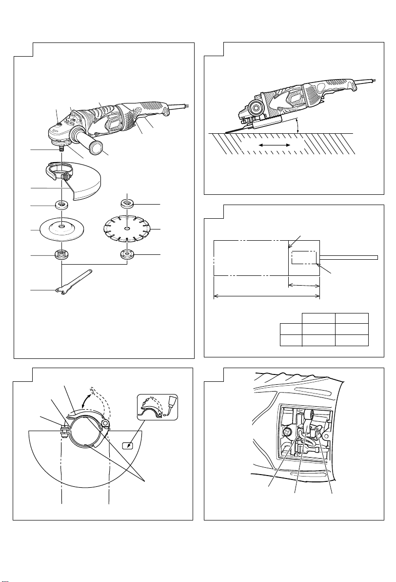
operation.
[Installing and adjusting the wheel guard]
䡬 Open the lever and insert the locating pin of wheel
guard, bringing it into line with the across flats of
packing ground.
䡬 Then, turn the wheel guard to a desired position
(for use).
䡬 Close the lever and fix it. If and when required, carry
out adjustments by tightening or loosening the screw.
䡬 If the lever does not move smoothly, apply some
lubricating oil to the sliding section between the set
piece and the lever.
䡬 Fasten the wheel guard at the position where the
across flats of the wheel guard positioning pin and
packing ground are aligned (the position where the
wheel guard is inserted), but do not use it.
5. Ensure that the depressed center wheel to be utilized
is the correct type and free of cracks or surface
defects. Also ensure that the depressed center wheel
is properly mounted and the wheel nut is securely
tightened. Refer to the section on “Assembling and
Disassembling the Depressed Center Wheel”.
4
Page 6

English
6. Conducting a trial run
Ensure that the abrasive products is correctly
mounted and tightened before use and run the tool
at no-load for 30 seconds in a safe position, stop
immediately if there is considerable vibration or if
other defects are detected.
If this condition occurs, check the machine to
determine the cause.
7. Confirm the spindle lock mechanism
Confirm that the spindle lock is disengaged by
pushing push button two or three times before
switching the power tool on (See Fig. 1).
8. Fixing the side handle
Screw the side handle into the gear cover.
PRACTICAL GRINDER APPLICATION
1. Pressure
To prolong the life of the machine and ensure a
first class finish, it is important that the machine
should not be overloaded by applying too much
pressure. In most applications, the weight of the
machine alone is sufficient for effective grinding.
Too much pressure will result in reduced rotational
speed, inferior surface finish, and overloading which
could reduce the life of the machine.
2. Grinding angle
Do not apply the entire surface of the depressed
center wheel to the material to be ground. As
shown in Fig. 3, the machine should be held at an
angle of 15° – 30° so that the external edge of the
depressed center wheel contacts the material at an
optimum angle.
3. To prevent a new depressed center wheel from
digging into the workpiece, initial grinding should
be performed by drawing the grinder across the
workpiece toward the operator (Fig. 3 direction B).
Once the leading edge of the depressed center
wheel is properly abraded, grinding may be
conducted in either direction.
4. Switch operation
Switch ON: Push the locking button forward and
Switch OFF: Press and release the switch lever.
5. Precautions immediately after finishing operation
After switching off the machine, do not put it down
until the depressed center wheel has come to a
complete stop. Apart from avoiding serious
accidents, this precaution will reduce the amount
of dust and swarf sucked into the machine.
CAUTION:
䡬 Check that the work piece is properly supported.
䡬 Ensure that ventilation openings are kept clear when
working in dusty conditions.
If it should become necessary to clear dust, first
disconnect the tool from the mains supply (use nonmetallic objects) and avoid damaging internal parts.
䡬 Ensure that sparks resulting from use do not create
a hazard e.g. do not hit persons, or ignite flammable
substances.
then press the switch lever.
* For continuous use, press the switch
lever. The switch lever is locked by
pushing the locking button forward
once again.
(*Subject to change depending on
area.)
䡬 Always use eye and ear protection.
Other personal protective equipment such as dust
mask, gloves, helmet and apron should be worn
when necessary.
If in doubt, wear the protective equipment.
䡬 When the machine is not use, the power source
should be disconnected.
ASSEMBLING AND DISASSEMBLING THE
DEPRESSED CENTER WHEEL
CAUTION:
Be sure to switch OFF and disconnect the attachment
plug from the receptacle to avoid a serious accident.
1. Assembling (Fig. 1)
(1) Turn the machine upside down so that the spindle
is facing upward.
(2) Mount the wheel washer onto the spindle.
(3) Fit the protruding part of the depressed center
wheel or diamond wheel onto the wheel washer.
(4) Screw the wheel nut onto the spindle.
(For diamond wheel assembling, use the wheel nut
with the convex side against the diamond wheel.)
(5) Insert the push button to prevent rotation of the
spindle, and tighten the wheel nut with the accessory
wrench, as shown in Fig.1.
2. Disassembling
Follow the above procedures in reverse.
CAUTION:
䡬 Comfirm that the depressed center wheel is mounted
firmly.
䡬 Confirm that the push button is disengaged by
pushing push button two or three times before
switching the power tool on.
MAINTENANCE AND INSPECTION
1. Inspecting the depressed center wheel
Ensure that the depressed center wheel is free of
cracks and surface defects.
2. Inspecting the mounting screws
Regularly inspect all mounting screws and ensure
that they are properly tightened. Should any of the
screws be loose, retighten them immediately. Failure
to do so could result in serious hazard.
3. Inspecting the carbon brushes (Fig. 4)
The motor employs carbon brushes which are
consumable parts.
When they become worn to or near the “wear
limit”, it could result in motor trouble. When an
auto-stop carbon brush is equipped, the motor will
stop automatically.
At that time, replace both carbon brushes with new
ones which have the same carbon brush numbers
shown in the figure. In addition, always keep carbon
brushes clean and ensure that they slide freely
within the brush holders.
4. Replacing carbon brushes (Fig. 5)
<Disassembly>
(1) Loosen the D4 tapping screw retaining the brush
cover and remove the brush cover.
(2) Use the auxiliary hexagonal wrench or small
screwdriver to pull up the edge of the spring that
is holding down the carbon brush. Remove the
edge of the spring toward the outside of the brush
holder.
5
Page 7

English
(3) Remove the end of the pig-tail on the carbon brush
from the terminal section of brush holder and then
remove the carbon brush form the brush holder.
<Assembly>
(1) Insert the end of the pig-tail of the carbon brush
in the terminal section of brush holder.
(2) Insert the carbon brush in the brush holder.
(3) Use the auxiliary hexagonal wrench or small
screwdriver to return the edge of the spring to the
head of the carbon brush.
(4) Mount the tail cover and tighten the D4 tapping
screw.
5. Maintenance of the motor
The motor unit winding is the very “heart” of the
power tool. Exercise due care to ensure the winding
does not become damaged and/or wet with oil or
water.
6. Service parts list
CAUTION:
Repair, modification and inspection of Hitachi Power
Tools must be carried out by an Hitachi Authorized
Service Center.
This Parts List will be helpful if presented with the
tool to the Hitachi Authorized Service Center when
requesting repair or other maintenance.
In the operation and maintenance of power tools,
the safety regulations and standards prescribed in
each country must be observed.
MODIFICATIONS:
Hitachi Power Tools are constantly being improved
HiKOKI
and modified to incorporate the latest technological
advancements.
Accordingly, some parts may be changed without
prior notice.
HiKOKI
HiKOKI
HiKOKI
NOTE:
Due to HITACHI’s continuing program of research and
HiKOKI's
development, the specifications herein are subject to
change without prior notice.
6
Page 8

Español
NORMAS GENERALES DE SEGURIDAD
¡ADVERTENCIA!
Lea todas las instrucciones
Si no se siguen las instrucciones de abajo podría producirse
una descarga eléctrica, un incendio y/o daños graves.
El término “herramienta eléctrica” en todas las
advertencias indicadas a continuación hace referencia a
la herramienta eléctrica que funciona con la red de
suministro (con cable) o a la herramienta eléctrica que
funciona con pilas (sin cable).
CONSERVE ESTAS INSTRUCCIONES
1) Área de trabajo
a) Mantenga la zona de trabajo limpia y bien
iluminada.
Las zonas desordenadas y oscuras pueden
provocar accidentes.
b) No utilice las herramientas eléctricas en entornos
explosivos como, por ejemplo, en presencia de
líquidos inflamables, gases o polvo.
Las herramientas eléctricas crean chispas que
pueden hacer que el polvo desprenda humo.
c) Mantenga a los niños y transeúntes alejados
cuando utilice una herramienta eléctrica.
Las distracciones pueden hacer que pierda el control.
2) Seguridad eléctrica
a) Los enchufes de las herramientas eléctricas tienen
que ser adecuados a la toma de corriente.
No modifique el enchufe.
No utilice enchufes adaptadores con herramientas
eléctricas conectadas a tierra.
Si no se modifican los enchufes y se utilizan tomas
de corriente adecuadas se reducirá el riesgo de
descarga eléctrica.
b) Evite el contacto corporal con superficies conectadas
a tierra como tuberías, radiadores y frigoríficos.
Hay mayor riesgo de descarga eléctrica si su
cuerpo está en contacto con el suelo.
c) No exponga las herramientas eléctricas a la lluvia
o a la humedad.
La entrada de agua en una herramienta eléctrica
aumentará el riesgo de descarga eléctrica.
d) No utilice el cable incorrectamente. No utilice el
cable para transportar, tirar de la herramienta
eléctrica o desenchufarla.
Mantenga el cable alejado del calor, del aceite, de
bordes afilados o piezas móviles.
Los cables dañados o enredados aumentan el
riesgo de descarga eléctrica.
e) Cuando utilice una herramienta eléctrica al aire
libre, utilice un cable prolongador adecuado para
utilizarse al aire libre.
La utilización de un cable adecuado para usarse
al aire libre reduce el riesgo de descarga eléctrica.
3) Seguridad personal
a) Esté atento, preste atención a lo que hace y utilice
el sentido común cuando utilice una herramienta
eléctrica.
No utilice una herramienta eléctrica cuando esté
cansado o esté bajo la influencia de drogas,
alcohol o medicación.
La distracción momentánea cuando utiliza
herramientas eléctricas puede dar lugar a
importantes daños personales.
b) Utilice equipo de seguridad. Utilice siempre una
protección ocular.
El equipo de seguridad como máscara para el
polvo, zapatos de seguridad antideslizantes, casco
o protección para oídos utilizado para condiciones
adecuadas reducirá los daños personales.
c) Evite un inicio accidental. Asegúrese de que el
interruptor está en “off” antes de enchufarlo.
El transporte de herramientas eléctricas con el
dedo en el interruptor o el enchufe de
herramientas eléctricas con el interruptor
encendido puede provocar accidentes.
d) Retire las llaves de ajuste antes de encender la
herramienta eléctrica.
Si se deja una llave en una pieza giratoria de la
herramienta eléctrica podrían producirse daños
personales.
e) No se extralimite. Mantenga un equilibrio
adecuado en todo momento.
Esto permite un mayor control de la herramienta
eléctrica en situaciones inesperadas.
f) Vístase adecuadamente. No lleve prendas sueltas
o joyas. Mantenga el pelo, la ropa y los guantes
alejados de las piezas móviles.
La ropa suelta, las joyas y el pelo largo pueden
pillarse en las piezas móviles.
g) Si se proporcionan dispositivos para la conexión
de extracción de polvo e instalaciones de recogida,
asegúrese de que están conectados y se utilizan
adecuadamente.
La utilización de estos dispositivos puede reducir
los riesgos relacionados con el polvo.
4) Utilización y mantenimiento de las herramientas
eléctricas
a) No fuerce la herramienta eléctrica. Utilice la
herramienta eléctrica correcta para su aplicación.
La herramienta eléctrica correcta trabajará mejor
y de forma más segura si se utiliza a la velocidad
para la que fue diseñada.
b) No utilice la herramienta eléctrica si el interruptor
no la enciende y apaga.
Las herramientas eléctricas que no pueden
controlarse con el interruptor son peligrosas y
deben repararse.
c) Desconecte el enchufe de la fuente eléctrica antes
de hacer ajustes, cambiar accesorios o almacenar
herramientas eléctricas.
Estas medidas de seguridad preventivas reducen
el riesgo de que la herramienta eléctrica se ponga
en marcha accidentalmente.
d) Guarde las herramientas eléctricas que no se
utilicen para que no las cojan los niños y no
permita que utilicen las herramientas eléctricas
personas no familiarizadas con las mismas o con
estas instrucciones.
Las herramientas eléctricas son peligrosas si son
utilizadas por usuarios sin formación.
e) Mantenimiento de las herramientas eléctricas.
Compruebe si las piezas móviles están mal
alineadas o unidas, si hay alguna pieza rota u
otra condición que pudiera afectar al
funcionamiento de las herramientas eléctricas.
Si la herramienta eléctrica está dañada, llévela a
reparar antes de utilizarla.
7
Page 9

Español
Se producen muchos accidentes por no realizar
un mantenimiento correcto de las herramientas
eléctricas.
f) Mantenga las herramientas de corte afiladas y
limpias.
Las herramientas de corte correctamente
mantenidas con los bordes de corte afilados son
más fáciles de controlar.
g) Utilice la herramienta eléctrica, los accesorios y las
brocas de la herramienta, etc., de acuerdo con estas
instrucciones y de la manera adecuada para el tipo
de herramienta eléctrica, teniendo en cuenta las
condiciones laborales y el trabajo que se va a realizar.
La utilización de la herramienta eléctrica para
operaciones diferentes a pretendidas podría dar
lugar a una situación peligrosa.
5) Revisión
a) Lleve su herramienta a que la revise un experto
cualificado que utilice sólo piezas de repuesto
idénticas.
Esto garantizará el mantenimiento de la seguridad
de la herramienta eléctrica.
PRECAUCIÓN
Mantenga a los niños y a las personas enfermas alejadas.
Cuando no se utilicen, las herramientas deben
almacenarse fuera del alcance de los niños y de las
personas enfermas.
PRECAUCIONES AL UTILIZAR LA
AMOLADORA ANGULAR
1. Nunca trabajar con estas herramientas eléctricas sin
cubiertas protectoras de la muela.
2. Compruebe que la velocidad marcada en la muela
sea igual o mayor que la velocidad nominal de la
amoladora.
Emplee sólo muelas de centro hundido con una
velocidad nominal de 80 m/s o más.
3. Compruebe que las dimensiones de la muela sean
compatibles con la amoladora y que la muela encaja
en el husillo.
4. Las muelas abrasivas se deben almacenar y tratar
con cuidado, de conformidad con las instrucciones
del fabricante.
5. Inspeccione la muela rectificadora antes del uso, y
no utilice productos descascarados, agrietados o
defectuosos de cualquier otro manera.
6. Sujetar siempre firmemente el asidero del cuerpo
y el asidero lateral de la herramienta. De lo contrario
la contrafuerza producida podría causar un
funcionamiento impreciso e incluso peligroso.
7. No utilice las muelas de tallado para el amolado
lateral.
8. No utilice los bujes o adaptadores de reducción
separados para adaptar muelas abrasivas de orificio
grande.
9. La muela continúa girando aún después de apagar
la herramienta.
ESPECIFICACIONES
Modelos G18SCY G18UAY G18SEY G18UBY G23SCY G23UAY G23SEY G23UBY
Voltaje (por áreas)*
Acometida*
Velocidad marcha en vacio 8500 /min 6600 /min
Diámetro exterior 180 mm 230 mm
Muela Diámetro del agujero 22 mm
Velocidad periférica 80 m/s
2
Peso*
*1 Verificar indefectiblemente los datos de la placa de características de la máquina, pues varían de acuerdo al país
de destino.
*2 Peso: Cuerpo principal solamente
1
1
2400W 2600W 2400W 2600W
(110V, 120V, 230V, 240V)
5,1 kg
ACCESORIOS ESTANDAR
(1) Llave para tuercas ................................................... 1
(2) Asidero lateral .......................................................... 1
Las ruedas centrales abombadas no se proveen como
accesorios estándar.
Los accesorios estándar están sujetos a cambio sin previo
aviso.
APLICACIONES
䡬 Eliminación de rebabas de juntas y acabado de
diversos tipos de acero, bronce y aluminio,
materiales y fundiciones.
䡬 Alisado de secciones soldadas o secciones cortadas
por medio de soldadura.
䡬 Alisado de resina sintética, pizarra,ladrillo, mármol,
etc.
8
䡬 Corte de hormigón sintético, piedra, ladrillos, mármol
y materiales similares.
ANTES DE LA PUESTA EN MARCHA
1. Alimentación
Asegurarse de que la alimentación de red que ha
de ser utilizada responda a las exigencias de
corriente especificadas en la placa de características
del producto.
2. Conmutador de alimentación
Asegurarse de que el conmutador de alimentación esté
en la posición OFF (desconectado). Si la clavija está
conectada en la caja del enchufe mientras el conmutador
de alimentación está en posición ON (conectado) las
herramientas eléctricas empezarán a trabajar
inmediatamente, provocando un serio accidente.
Page 10

Español
3. Cable de prolongación
Cuando está alejada el área de trabajo de la red
de alimentación, usar un cable de prolongación de
un grosor y potencia nominal suficiente. El cable
de prolongación debe ser mantenido lo más corto
posible.
4. Montar y ajustar la cubierta protectora de muela
La cubierta protectora de muela es un dispositivo
protector para evitar heridas, en caso de que la
muela de alisado se quiebre durante la operación.
Asegurarse de que la cubierta protectora esté bién
montada y apretada antes de comenzar con la
operación de alisado.
[Instalación y ajuste del protector de la rueda]
䡬 Instalación y ajuste del protector de la rueda Abra
la palanca e inserte el pasador de posicionamiento
del protector de la rueda, alineándolo con la distancia
entre caras del prensaestopas.
䡬 Luego, gire el protector de la rueda hasta la posición
deseada (de uso).
䡬 Cierre la palanca y fíjela. De requerirse, realice el
ajuste apretando o aflojando el tornillo.
䡬 Si la palanca no se mueve con suavidad, aplique
una ligera capa de aceite lubricante en la sección
deslizante entre la pieza de ajuste y la palanca.
䡬 Sujete el protector de la muela en una posición que
permita que las entre caras del pasador de
posicionamiento del protector de la muela y del
prensaestopas se encuentren alineados (la posición
en que se inserta el protector de la muela), pero
no lo utilice.
5. Asegurarse de que la muela de alisado a utilizar sea
de tipo correcto y libre de rajas o defectos de superficie.
También asegurarse de que la muela de alisado esté
montada debidamente y que la contratuerca de muela
esté apretada firmemente. Dirigirse a la sección de
“montaje y desmontaje de la muela alisado”.
6. Realizar una prueba
Asegúrese de que los productos abrasivos estén
correctamente montados y apretados antes del uso,
y haga funcionar la herramienta sin carga durante
30 segundos en una posición segura. Apáguela
inmediatamente si nota una vibración considerable
u otros defectos.
Si se produce esta condición, inspeccione la
herramienta para determinar la causa.
7. Confirmar el mechanismo de bloqueo del eje
Confirmar que el mechanismo del bloqueo del eje
esté desconectado, apretando el botón pulsador de
cierre dos o tres veces, antes de conectar el aparato
eléctrico (véase en la Fig. 1).
8. Instalación del asidero lateral
Atornille el asidero lateral en la cubierta de
engranaje.
APLICACION PRACTICA DEL ALISADOR
1. Presión
Para prolongar la vida da la máquina y asegurar
un acabado de primera clase, es importante que
la máquina no sea recalentada aplicando demasiada
presión. En la mayoría de las aplicaciones el sólo
peso de la máquina, es suficiente para un alisado
efectivo. Demasiada presión ocasionaría una
reducida velocidad rotacional, inferior acabado de
superficie y recalentamiento que reduciría la vida
de la máquina.
2. Angulo de alisado
No aplicar toda la superficie de la muela de alisado
al material a alisar. Como muestra en Fig. 3, la
máquina deberá ser mantenida en un ángulo de 15°
– 30° de tal manera que el canto externo de la
muela de alisado contacte la pieza de trabajo en
un ángulo óptimo.
3. Para prevenir que una nueva muela de alisado cave
la pieza de trabajo, el alisado inicial debe ser llevado
a cabo tirando de la amoladora por encima de la
pieza de trabajo hacia el operario (Fig. 3 dirección
B). Una véz que el canto directriz de la muela de
alisado esté bién raspado, el alisado puede ser
realizado en cualquier dirección.
4. Operación del conmutador
Puesta en funcionamento:
Parada: Presione y suelte la palanca del
5. Precauciones inmediatamente después de haber
acabado la operación
Después de desconectar la máquina no posarla
antes de que la muela de alisado se haya parado
completamente. Aparte de evitar serios accidentes,
esta precaución reduciría la cantidad de polvo y
limaduras absorbidos por la máquina.
PRECAUCIÓN:
䡬 Compruebe que la pieza de trabajo esté
correctamente soportada.
䡬 Cuando trabaje en ambientes polvorientos,
asegúrese de que las aberturas de ventilación se
mantengan libres de obstrucciones.
Si llegara a ser necesario eliminar el polvo, primero
desconecte la herramienta del tomacorriente de la
red (use objetos no metálicos) y evite que se dañen
las piezas internas.
䡬 Asegúrese de que las chispas resultantes del uso
no representen peligro alguno, por ejemplo, que no
alcancen a las personas, ni que incendien sustancias
inflamables.
䡬 Utilice siempre protectores oculares y auriculares.
Otros equipos de protección personal, como máscara
contra el polvo, guantes, casco y delantal se deben
usar según se requiera.
En caso de dudas, utilice el equipo de protección.
䡬 Cuando no se usa la máquina, debe estar
desconectada la acometida de red.
Presione el botón de seguridad hacia
adelante y depués presione la palanca
del interruptor.
* Para una utilización continua, presione
la palanca del interruptor. Esta
palanca quedará trabada al volver a
presionar el botón de seguridad hacia
adelante.
(*Sujeto a cambios dependiendo de
la zona.)
interruptor.
MONTAJE Y DESMONTAJE DE LA MUELA
ALISADO
PRECAUCIÓN:
Cerciórese de desconectar la alimentación y
desenchufe el enchufe de la toma de alimentación
de la red para evitar averías serias.
9
Page 11

Español
1. Montaje (Fig. 1)
(1) Volver la máquina boca abajo de tal manera que
el eje esté mirando hacia arriba.
(2) Montar la arandela molar en el eje.
(3) Montar la protuberancia de la muela de alisado o
la muela adiamantada en la arandela molar.
(4) Atornillar la contratuerca molar en el eje.
(Para instalar la muela adiamantada, emplee la
contratuerca molar con el lado convexo hacia la
muela adiamantada.)
(5) Insertar el pulsador para prevenir la rotación del
eje y apretar la contratuerca molar con llave
accesoria como muestra en la Fig. 1.
2. Desmontaje
Seguir los procedimientos antedichos a la inversa.
PRECAUCIÓN:
䡬 Confirme que la muela de alisado esté firmemente
montada.
䡬 Confirmar que el botón esté desactivado presionando
el botón dos o tres veces antes de conectar la
alimentación de la herramienta eléctrica.
MANTENIMIENTO E INSPECCION
1. Inspeccionar la muela de alisado
Asegurarse de que la muela de alisado esté libre
de rajas y defectos en la superficie.
2. Inspeccionar los tornillos de montaje
Regularmente inspeccionar todos los tornillos de
montaje y asegurarse de que estén apretados
firmemente. Si cualquier tornillo estuviera suelto,
volver a apretarlo inmediatamente. El no hacer esto
provocaría un riesgo serio.
3. Inspeccionar los carbones de contacto (Fig. 4)
El motor emplea escobillas de carbón que son
partes consumibles.
Cuando se gastan o están cerca del “limite de
desgaste” pueden causar problemas al motor.
Al equiparse la escobilla de carbón de parada
automática, el motor se detendrá automáticamente
en ese momento hay que proceder a cambiar ambas
escobillas de carbón por la nuevas, que tengan los
mismos números de escobillas de carbón como se
muestra en la figura. Además siempre hay que
mantener las escobillas de carbón limpias y
asegurarse de que se muevan libremente en sus
porta-escobillas.
4. Reemplazar el carbón de contacto (Fig. 5)
<Desmontaje>
(1) Afloje el tornillo autorroscante D4 que retiene a la
cubierta de la escobilla y retire esta cubierta.
(2) Emplee la llave macho hexagonal auxiliar o un
pequeño destornillador para tirar del borde del
resorte helicoidal que empuja hacia abajo el carbón
de contacto. Extraiga el dorde del resorte hacia
afuera el soporte del carbón de contacto.
(3) Extraiga la sección del soporte carbón de contacto
en la sección del terminal del soporte del carbón
de contacto y después extraiga el carbón de contacto
de su soporte.
<Montaje>
(1) Inserte el extremo del conductor helicoidal del carbón
de contacto en la sección del terminal del soporte
del carbón de contacto.
(2) Inserte el carbón de contacto en el soporte del
mismo.
10
(3) Emplee la llave macho hexahonal auxiliar o un
pequeño destornillador para devolver el borde del
resorte helicoidal hasta la cabeza del carbón de
contacto.
(4) Cierre la cubierta de la cola y apriete el tornillo
autorroscante D4.
5. Mantenimiento de motor
La unidad de bobinado del motor es el verdadero
“corazón” de las herramientas eléctricas. Prestar el
mayor cuidado a asegurarse de que el bobinado
no se dañe y/o se humedezca con aceite o agua.
6. Lista de repuestos
PRECAUCIÓN:
La reparación, modificación e inspección de las
herramientas eléctricas Hitachi deben ser realizadas
por un Centro de Servicio Autorizado de Hitachi.
Esta lista de repuestos será de utilidad si es
presentada junto con la herramienta al Centro de
Servicio Autorizado de Hitachi, para solicitar la
reparación o cualquier otro tipo de mantenimiento.
En el manejo y el mantenimiento de las herramientas
eléctricas, se deberán observar las normas y
reglamentos vigentes en cada país.
MODIFICACIONES:
Hitachi Power Tools introduce constantemente
HiKOKI
mejoras y modificaciones para incorporar los últimos
avances tecnológicos.
Por consiguiente, algunas partes pueden ser
modificadas sin previo aviso.
OBSERVACION:
Debido al programa continuo de investigación y
desarrollo de HITACHI éstas especificaciones están
sujetas a cambio sin previo aviso.
HiKOKI's
HiKOKI
HiKOKI,
HiKOKI.
Page 12

一般安全規則
警告!
請通讀本說明書
若不遵守下列注意事項,可能會導致電擊、火災及/或
嚴重傷害。
下述警告中的術語「電動工具」,指插電 (有線) 電
動工具或電池 (無線) 電動工具。
請妥善保管本說明書
1) 工作場所
a) 工作場所應打掃乾淨,並保持充分的亮度。
雜亂無章及光線昏暗容易導致事故。
b) 請勿在易爆炸的環境中操作電動工具,如存在
易燃液體、氣體或粉塵的環境中。
電動工具產生的火花可能會點燃煙塵。
c) 操作電動工具時,孩童與旁觀者勿靠近工作場
所。
工作時分神可能會造成工具失控。
2) 電氣安全
a) 電動工具插頭必須與插座相配。
不得以任何形式改裝插頭。
不得對接地的電動工具使用任何轉接插頭。
原裝插頭及相配插座將會減少電擊的危險。
b) 應避免身體與大地或接地表面,如管道、散熱
器、爐灶、冰箱等的接觸。
若身體接觸大地或接地表面,更會增加電擊的
危險。
c) 電動工具不可任其風吹雨打,或置於潮濕的環
境中。
水進入電動工具也會增加電擊的危險。
d) 要小心使用電線。不要用電線提拉電動工具,
或拉扯電線來拆除工具的插頭。
電線應遠離熱源、油液,並避免接觸到銳利邊
緣或轉動部分。
電線損壞或攪纏在一起會增加電擊的危險。
e) 在室外操作電動工具時,請使用專用延伸線。
使用專用延伸線可降低電擊的危險。
3) 人身安全
a) 保持高度警覺,充分掌握情況,以正常的判斷
力從事作業。
疲勞狀態或服藥、飲酒後,請勿使用電動工具。
操作電動工具時,一時的疏忽都可能造成嚴重
的人身傷害。
中國語
b) 使用安全設備。始終配戴安全眼鏡。
在適用條件下,使用防塵面罩、防滑膠鞋、安
全帽或聽覺保護裝置等安全設備,都會減少人
身傷害。
c) 謹防誤開動。插接電源前,請先確認開關是否
已切斷。
搬移電動工具時指頭接觸開關,或接通開關狀
態下插上電源插座,都容易導致事故。
d) 開動前務必把調整用鍵和扳手類拆除下來。
扳手或鍵留在轉動部分上,可能會造成人身傷
害。
e) 要在力所能及的範圍內進行作業。作業時腳步
要站穩,身體姿勢要保持平衡。
這樣在意外情況下可以更好地控制工具。
f) 工作時衣服穿戴要合適。不要穿著過於寬鬆的
衣服或佩帶首飾。頭髮、衣角和手套等應遠離
轉動部分。
鬆散的衣角、首飾或長髮都可能會捲入轉動部
分。
g) 如果提供連接除塵和集塵的設備,請確認是否
已經連接好並且使用正常。
使用這些設備可降低粉塵引起的危險。
4) 電動工具的使用和維護
a) 不要使勁用力推壓。應正確使用電動工具。
正確使用才能讓工具按設計條件有效而安全地
工作。
b) 如果電動工具不能正常開關,切勿使用。
無法控制開關的電動工具非常危險,必須進行
修理。
c) 進行調整、更換附件或存放工具前,請拆除電
源插頭。
此類預防安全措施可減少誤開動工具的危險。
d) 閒置不用的工具,應存放在孩童夠不到的地
方;不熟悉電動工具或本說明書的人員,不允
許操作本工具。
未經培訓的人員使用電動工具非常危險。
e) 妥善維護工具。檢查轉動部分的對準、連接,
各零件有無異常,及其他足以給工作帶來不良
影響的情況。
如有損壞,必須修理後才能使用。
許多事故都是因工具維護不良引起的。
f) 保持工具鋒利、清潔。
正確維護工具,使其保持鋒利,作業順暢,便
於控制。
11
Page 13

中國語
g) 請根據本說明書,按照特殊類型電動工具的方
式,使用本工具、附件及鑽頭,並考慮作業條
件及具體的作業情況。
電動工具用於規定外的作業,可能會導致危險
狀況。
5) 維修
a) 本電動工具的維修必須由專業人員使用純正配
件進行。
這樣才能確保電動工具的安全性。
注意事項:
不可讓孩童和體弱人士靠近工作場所。
應將不使用的工具存放在孩童和體弱人士伸手不及的
地方。
使用手提圓盤電磨機時應注意事項
1. 沒有砂輪防護裝置千萬不要使用圓盤電磨機這種動
力工具。
2. 確認砂輪上所標示的轉速等於或大於電磨機的額定
轉速只能使用額定轉速為 80 m秒 以上的砂輪。
3. 確保砂輪尺寸與電磨機相符、砂輪與主軸相配。
4. 須按照廠家的使用說明書小心存放和使用磨輪。
5. 使用前檢查砂輪,不要使用破損、有裂縫的或有其
他缺陷的產品
6. 始終抓緊電動工具的機身手柄和側柄。否則,所產
生的反作用力可能會導致錯誤的、甚至是危險的操
作。
7. 請勿使用切斷砂輪進行側面研磨。
8. 請勿將獨立的減速軸襯或接頭用於大孔砂輪。
9. 在切斷本電動工具的電源之後,砂輪仍會繼續旋轉
一段時間。
規 格
型式 G18SCY 台灣 G18SCY G18UAY G18SEY G18UBY G23SCY G23UAY G23SEY G23UBY
電壓(按地區)*1110V (110V, 120V, 230V, 240V)
輸入功率*
額定輸出功率 1000W 1600W 1750W 1600W 1750W
無負荷速度 8500 轉分 6600 轉分
砂輪 孔徑 22 mm
重量*
*1當須改變地區時應檢查產品上的銘牌。
*2僅限於本體
1
外徑 180 mm 230 mm
外緣速度 80 m秒
2
1560W 2400W 2600W 2400W 2600W
5.1 kg
標 準 附 件
(1) 扳手 ................................... 1
(2) 側柄 ................................... 1
砂輪不作為標準附件附送。
標準附件可能不預先通告而徑予更改。
用 途
䡬 用於去除鑄品毛刺,飛邊等物及拋光各種型號的
鋼,青銅,鋁及鑄造品。
䡬 研磨焊接部分或研磨用焊接切割的部分。
12
䡬 合成樹脂、石板、磚、大理石等的研磨。
䡬 混凝土、石頭、磚、大理石等的切削。
作 業 之 前
1. 電源
確認所使用的電源與工具銘牌上標示的規格是否相
符。
2. 電源開關
確認電源開關是否切斷。若電源開關接通,則插頭
插入電源插座時電動工具將出其不意地立刻轉動,
從而招致嚴重事故。
Page 14

中國語
3. 延伸線纜
若作業場所移到離開電源的地點,應使用厚度足
夠、額定電容的延伸線纜,並且要盡可能地短些。
4. 安裝並調整輪罩
輪罩是一種保護裝置,用來防止作業中因砂輪破裂
而受傷。開始研磨作業之前,請確認輪罩裝好緊
固。
〔安裝和調整輪罩的方法〕
䡬 打開手柄,對準墊座的對邊寬度並插入輪罩的定位
鎖。
䡬 然後將輪罩轉動到所需的位置(使用位置)。
䡬 關閉手柄使之固定。若有必要,擰緊或擰鬆螺絲進
行調整。
䡬 手柄移動不暢時,請給設定鎖與手柄的連接部分加
注潤滑油。
䡬 請勿在輪罩的定位銷與墊座的對邊寬度一致的位置
(輪罩的插入位置)固定輪罩並使用。
5. 確認要使用的砂輪屬於正確類型、沒有裂紋或表面
缺陷。同時也要確認砂輪裝好,輪螺母緊固。參照
“砂輪的裝卸”一節。
6. 試行運轉
在使用前確保已正確安裝並擰緊研磨產品,並在安
全場所在空載狀態下運轉 30 秒鐘,若有較大的振
動或察覺到其他缺陷,則應立即停止試運轉。
遇此情況時,檢查電動工具以究明原因。
7. 檢查主軸鎖的裝置
在打開電源開關之前,撳兩、三下鎖定銷檢查鎖定
銷是否被釋放(圖 1)。
8. 固定側柄
把側柄旋進齒輪罩。
3. 用新砂輪首次進行研磨,應將手提圓盤電磨機由對
面橫過工件往操作人員這邊拉,以免挖入工作(圖
3 的 B 方向)。等砂輪的前緣適當磨損,就可往
任何方向進行研磨。
4. 手提圓盤電磨機的開關
接通:將開關鎖往前推,接著按開關的手柄開關
就被接通。
* 長時間使用時,只須再度將開關徑前
推,開關將上鎖。
(*依地區而異。)
斷開:按緊開關的手柄,然後釋放,開關就會斷
開。
5. 收工後的注意事項
關掉機器之後,需等手提圓盤電磨機完全停止才能
放下,以免造成嚴重事故,而且還可減少吸入機器
的塵埃與切削量。
注意:
䡬 檢查工件已被正確固定。
䡬 在多塵的條件下工作時,確保通風口暢通無堵
塞現象。
如果需要清除灰塵,首先使電動工具斷開電源
(使用非金屬物品)並避免損壞內部零件。
䡬 確保使用時產生的火花不會引起危險:例如,
不要濺在身體上或點燃易燃物。
䡬 始終採用視力和聽力保護。
必要時應使用其他個人保護裝置,如口罩、手
套、頭盔和圍裙等。
拿不準時,請使用保護裝置。
䡬 未使用本電動工具時,請斷開電源。
實用手提圓盤電磨機的應用
1. 壓力
本機不可施加過大壓力使其過載,以延長使用壽命
並確保加工品質。在大部份的用法中,機器本身的
重量即夠研磨。加壓過大將導致轉速降低、表面加
工不良以及過載,從而縮短機器壽命。
2. 研磨角度
切勿將砂輪之全表面施加於要研磨的材料上。如圖
3 所示,機器應保持 15°-30°,使砂輪的外緣以
最佳角度與工件相接觸。
砂輪的裝卸
注意:
確認開關已斷開並且從電源插座中拔去電源插頭以
避免嚴重事故。
1. 裝配(圖 1)
(1) 將機器翻過去,使主軸朝上。
(2) 將砂輪墊圈裝於主軸上。
(3) 將砂輪或金剛輪的突出部裝入砂輪墊圈。
(4) 將砂輪螺帽旋入主軸。
(使用金剛輪時,請把砂輪螺帽的凸面裝到金剛
輪的相反方向上,並且把螺帽擰到主軸上。)
13
Page 15

中國語
(5) 按下鎖定銷以防止主軸轉動,並如圖 1 所示用
附送的扳手擰緊砂輪螺帽。
2. 拆卸
按照上述步驟相反的順序進行拆卸。
注意:
䡬 確認砂輪安裝是否牢固。
䡬 確認鎖定銷被解除鎖定。可在打開電源開關之
前通過撳兩、三次鎖定銷進行檢查。
維 護 和 檢 查
1. 檢查砂輪
檢查砂輪確無破裂和表面缺隱。
2. 檢查安裝螺絲
要經常檢查安裝螺絲是否緊固妥善。若發現螺絲鬆
了,應立即重新扭緊,否則會導致嚴重的事故。
3. 檢查碳刷(圖 4)
電動機裏的碳刷是一種消耗品。
碳刷一旦使用到磨損極限,電動機就會出現各種障
礙;如果所使用的碳刷是“自停式”,電動機將自
動地停止轉動。
遇到上述情況,應立即換上與圖上代號一致的新碳
刷。此外,碳刷應經常保持乾淨狀態,以保證能在
刷握裏自由滑動。
4. 更換碳刷(圖 5)
〈拆卸〉
(1) 擰鬆固定碳刷蓋的 D4 自攻螺絲釘,拆下碳刷
蓋。
(2) 使用六角形扳手或小螺絲刀拔起固定碳刷的彈簧
邊緣。朝刷握的外側方拆下彈簧邊緣。
(3) 從刷握的端部取下碳刷上的引出端,然後從刷握
裡拆下碳刷。
〈安裝〉
(1) 將碳刷的引線端插入刷握的端部。
(2) 將碳刷裝入刷握。
(3) 使用六角形扳手或小螺絲刀使彈簧邊緣回到碳刷
頭處。
(4) 安上尾部蓋並擰緊 D4 自攻螺絲釘。
5. 電動機的維護
電動機繞線是電動工具的“心臟部”。應仔細檢查
有無損傷,是否被油液或水沾濕。
6. 維修部件目錄
注意:
HiKOKI HiKOKI
日立電動工具的修理、維護和檢查必須由日立所認
可的維修中心進行。
當尋求修理或其他維護時,將本部件目錄與工具一
起提交給日立所認可的維修中心會對您有所幫助。
在操作和維護電動工具中,必須遵守各國的安全規
則和標准規定。
改進:
HiKOKI
日立電動工具隨時都在進行改進以適應最新的技術
進步。
因此,有些部件可能未預先通知而進行改進。
註:
為求改進,本手冊所載規格可能不預先通知而徑予
更改。
HiKOKI
14
Page 16

8
2
Item
Item
G18SCY
16
×
Part Name Q’TY
TAPPING SCREW (W/FLANGE) D4
46 WHEEL NUT M14×21
47 DUST SEAL 1
48 BALL BEARING 6200VVCMPS2L 1
49 BEARING BUSHING 1
50 HOUSING 1
51 BRUSH COVER 1
52 HANDLE DAMPER 1
53
54 CARBON BRUSH 7×17×22.5 2
55 BRUSH HOLDER SET 2
No.
2
4
14
×
35
×
Part Name Q’TY
SEAL LOCK HEX. SOCKET HD. BOLT M5
TAPPING SCWER (W/FLANGE) D5
1
2 SPRING WASHER M5 2
3
4 PUSHING BUTTON 1
5 SPRING 1
No.
6 GEAR COVER ASS’Y 1
56 HANDLE (B) 1
7 SPECIAL NUT M10 1
8 PINION 1
9 SEAL WASHER 1
10 FELT PACKING 1
11 BALL BEARING 6301DDCMPS2L 1
BRAND LABEL
57 BRUSH COVER 1
58 HITACHI LABEL 1
59 NAME PLATE 1
60 O-RING (I.D. 24.7) 1
12 RUBBER RING (B) 1
13 BEARING COVER (A) 1
14 ARMATURE 1
15 FAN GUIDE 1
16
×
TAPPING SCREW (W/FLANGE) D4
61 O-RING (I.D. 31.2) 1
62 SWITCH 1
63 CORD CLIP 1
64
65 SWITCH COVER 1
66 HANDLE (A) 1
67 TERMINAL M4.0 2
68 TUBE (D) 2
69 CORD ARMOR 1
16 HEX. HD. TAPPING SCREW D5×75 2
17 STATOR 1
18 FELT WASHER 1
19 SIDE HANDLE 1
20 O-RING 1
21 LOCK PIN 1
22 GEAR ASS’Y 1
23 RETAINING RING FOR D10 SHAFT 1
24 COUPLING COVER 1
70 CORD 1
501 WRENCH 1
4
HEX. SOCKET HD. BOLT (W/FLANGE) M5×16
25 COUPLING DAMPER 4
26 COUPLING 1
27 GEAR 1
28 MACHINE SCREW M5×10 2
29 BEARING COVER (B) 1
30 BALL BEARING 6302DDCMPS2L 1
31 FELT PACKING (B) 1
32 SPINDLE 1
33 SEAL PLATE 1
34 PACKING GLAND 1
35
36 LABEL 1
37 SET PIN 1
1
RETAINING RING (E-TYPE) FOR D5 SHAFT
38 LEVER 1
39 BOLT M8×22 1
40 SPRING WASHER M8 1
41 SET PIECE 1
42
43 WHEEL GUARD ASS’Y 1
44 WHEEL WASHER (A) 1
45 D. C. WHEELS 180MM A24R 1
15
Page 17

Part Name Q’TY
8
2
Item
Item
G18SEY
TAPPING SCREW (W/FLANGE) D4×16
46 WHEEL NUT M14×21
47 DUST SEAL 1
48 BALL BEARING 6200VVCMPS2L 1
49 BEARING BUSHING 1
50 HOUSING 1
51 BRUSH COVER 1
52 HANDLE DAMPER 1
53
54 CARBON BRUSH 7×17×22.5 2
55 BRUSH HOLDER SET 2
No.
2
4
14
×
35
×
Part Name Q’TY
SEAL LOCK HEX. SOCKET HD. BOLT M5
TAPPING SCWER (W/FLANGE) D5
1
2 SPRING WASHER M5 2
3
4 PUSHING BUTTON 1
5 SPRING 1
No.
6 GEAR COVER ASS’Y 1
56 HANDLE (B) 1
7 SPECIAL NUT M10 1
8 PINION 1
9 SEAL WASHER 1
10 FELT PACKING 1
11 BALL BEARING 6301DDCMPS2L 1
BRAND LABEL
57 BRUSH COVER 1
58 HITACHI LABEL 1
59 NAME PLATE 1
60 O-RING (I.D. 24.7) 1
12 RUBBER RING (B) 1
13 BEARING COVER (A) 1
14 ARMATURE 1
15 FAN GUIDE 1
TAPPING SCREW (W/FLANGE) D4×16
61 O-RING (I.D. 31.2) 1
62 SWITCH 1
63 CORD CLIP 1
64
65 HANDLE (A) 1
66 TUBE (D) 2
67 CORD ARMOR 1
68 CORD 1
501 WRENCH 1
4
HEX. SOCKET HD. BOLT (W/FLANGE) M5×16
16 HEX. HD. TAPPING SCREW D5×75 2
17 STATOR 1
18 FELT WASHER 1
19 SIDE HANDLE 1
20 O-RING 1
21 LOCK PIN 1
22 GEAR ASS’Y 1
23 RETAINING RING FOR D10 SHAFT 1
24 COUPLING COVER 1
25 COUPLING DAMPER 4
26 COUPLING 1
27 GEAR 1
28 MACHINE SCREW M5×10 2
29 BEARING COVER (B) 1
30 BALL BEARING 6302DDCMPS2L 1
31 FELT PACKING (B) 1
32 SPINDLE 1
33 SEAL PLATE 1
34 PACKING GLAND 1
35
36 LABEL 1
37 SET PIN 1
1
RETAINING RING (E-TYPE) FOR D5 SHAFT
38 LEVER 1
39 BOLT M8×22 1
40 SPRING WASHER M8 1
41 SET PIECE 1
42
43 WHEEL GUARD ASS’Y 1
44 WHEEL WASHER (A) 1
45 D. C. WHEELS 180MM A24R 1
16
Page 18

8
16
×
22.5 2
×
21
×
Part Name Q’TY
2
16
×
Item
Item
G18UAY
TAPPING SCREW (W/FLANGE) D4
46 WHEEL NUT M14
47 DUST SEAL 1
48 BALL BEARING 6200VVCMPS2L 1
49 BEARING BUSHING 1
50 HOUSING 1
51 BRUSH COVER 1
52 HANDLE DAMPER 1
53
54 CARBON BRUSH 7×17
55 BRUSH HOLDER SET 2
No.
2
4
14
×
35
×
Part Name Q’TY
SEAL LOCK HEX. SOCKET HD. BOLT M5
TAPPING SCWER (W/FLANGE) D5
1
2 SPRING WASHER M5 2
3
4 PUSHING BUTTON 1
5 SPRING 1
No.
6 GEAR COVER ASS’Y 1
56 HANDLE (B) 1
7 SPECIAL NUT M10 1
8 PINION 1
9 SEAL WASHER 1
10 FELT PACKING 1
11 BALL BEARING 6301DDCMPS2L 1
BRAND LABEL
57 BRUSH COVER 1
58 HITACHI LABEL 1
59 NAME PLATE 1
60 O-RING (I.D. 24.7) 1
12 RUBBER RING (B) 1
13 BEARING COVER (A) 1
14 ARMATURE 1
15 FAN GUIDE 1
TAPPING SCREW (W/FLANGE) D4
61 O-RING (I.D. 31.2) 1
62 RESISTOR 1
63 SWITCH 1
64 CORD CLIP 1
65
66 HANDLE (A) 1
67 TUBE (D) 2
68 CORD ARMOR 1
2
HEX. HD. TAPPING SCREW D5×75
16
17 STATOR 1
18 FELT WASHER 1
1
RETAINING RING FOR D10 SHAFT
19 SIDE HANDLE 1
20 O-RING 1
21 LOCK PIN 1
22 GEAR ASS’Y 1
23
69 CORD 1
501 WRENCH 1
4
16
×
10 2
×
HEX. SOCKET HD. BOLT (W/FLANGE) M5
24 COUPLING COVER 1
25 COUPLING DAMPER 4
26 COUPLING 1
27 GEAR 1
28 MACHINE SCREW M5
29 BEARING COVER (B) 1
30 BALL BEARING 6302DDCMPS2L 1
31 FELT PACKING (B) 1
32 SPINDLE 1
33 SEAL PLATE 1
34 PACKING GLAND 1
35
36 LABEL 1
37 SET PIN 1
22 1
×
38 LEVER 1
39 BOLT M8
1
RETAINING RING (E-TYPE) FOR D5 SHAFT
40 SPRING WASHER M8 1
41 SET PIECE 1
42
43 WHEEL GUARD ASS’Y 1
44 WHEEL WASHER (A) 1
45 D. C. WHEELS 180MM A24R 1
17
Page 19

8
16
×
22.5 2
×
21
×
Part Name Q’TY
2
16
×
Item
Item
G18UBY
TAPPING SCREW (W/FLANGE) D4
46 WHEEL NUT M14
47 DUST SEAL 1
48 BALL BEARING 6200VVCMPS2L 1
49 BEARING BUSHING 1
50 HOUSING 1
51 BRUSH COVER 1
52 HANDLE DAMPER 1
53
54 CARBON BRUSH 7×17
55 BRUSH HOLDER SET 2
No.
2
4
14
×
35
×
Part Name Q’TY
SEAL LOCK HEX. SOCKET HD. BOLT M5
TAPPING SCWER (W/FLANGE) D5
1
2 SPRING WASHER M5 2
3
4 PUSHING BUTTON 1
5 SPRING 1
No.
6 GEAR COVER ASS’Y 1
56 HANDLE (B) 1
7 SPECIAL NUT M10 1
8 PINION 1
9 SEAL WASHER 1
10 FELT PACKING 1
11 BALL BEARING 6301DDCMPS2L 1
BRAND LABEL
57 BRUSH COVER 1
58 HITACHI LABEL 1
59 NAME PLATE 1
60 O-RING (I.D. 24.7) 1
12 RUBBER RING (B) 1
13 BEARING COVER (A) 1
14 ARMATURE 1
15 FAN GUIDE 1
TAPPING SCREW (W/FLANGE) D4
61 O-RING (I.D. 31.2) 1
62 RESISTOR 1
63 SWITCH 1
64 CORD CLIP 1
65
66 HANDLE (A) 1
67 TUBE (D) 2
68 CORD ARMOR 1
2
HEX. HD. TAPPING SCREW D5×75
16
17 STATOR 1
18 FELT WASHER 1
1
RETAINING RING FOR D10 SHAFT
19 SIDE HANDLE 1
20 O-RING 1
21 LOCK PIN 1
22 GEAR ASS’Y 1
23
69 CORD 1
501 WRENCH 1
4
16
×
10 2
×
HEX. SOCKET HD. BOLT (W/FLANGE) M5
24 COUPLING COVER 1
25 COUPLING DAMPER 4
26 COUPLING 1
27 GEAR 1
28 MACHINE SCREW M5
29 BEARING COVER (B) 1
30 BALL BEARING 6302DDCMPS2L 1
31 FELT PACKING (B) 1
32 SPINDLE 1
33 SEAL PLATE 1
34 PACKING GLAND 1
35
36 LABEL 1
37 SET PIN 1
22 1
×
38 LEVER 1
39 BOLT M8
1
RETAINING RING (E-TYPE) FOR D5 SHAFT
40 SPRING WASHER M8 1
41 SET PIECE 1
42
43 WHEEL GUARD ASS’Y 1
44 WHEEL WASHER (A) 1
45 D. C. WHEELS 180MM A24R 1
18
Page 20

8
2
Item
Item
G23SCY
16
×
Part Name Q’TY
TAPPING SCREW (W/FLANGE) D4
46 WHEEL NUT M14×21
47 DUST SEAL 1
48 BALL BEARING 6200VVCMPS2L 1
49 BEARING BUSHING 1
50 HOUSING 1
51 BRUSH COVER 1
52 HANDLE DAMPER 1
53
54 CARBON BRUSH 7×17×22.5 2
55 BRUSH HOLDER SET 2
No.
2
4
14
×
35
×
Part Name Q’TY
SEAL LOCK HEX. SOCKET HD. BOLT M5
TAPPING SCWER (W/FLANGE) D5
1
2 SPRING WASHER M5 2
3
4 PUSHING BUTTON 1
5 SPRING 1
No.
6 GEAR COVER ASS’Y 1
56 HANDLE (B) 1
7 SPECIAL NUT M10 1
8 PINION 1
9 SEAL WASHER 1
10 FELT PACKING 1
11 BALL BEARING 6301DDCMPS2L 1
BRAND LABEL
57 BRUSH COVER 1
58 HITACHI LABEL 1
59 NAME PLATE 1
60 O-RING (I.D. 24.7) 1
12 RUBBER RING (B) 1
13 BEARING COVER (A) 1
14 ARMATURE 1
15 FAN GUIDE 1
16
×
TAPPING SCREW (W/FLANGE) D4
61 O-RING (I.D. 31.2) 1
62 SWITCH 1
63 CORD CLIP 1
64
65 SWITCH COVER 1
66 HANDLE (A) 1
67 TERMINAL M4.0 2
68 TUBE (D) 2
69 CORD ARMOR 1
16 HEX. HD. TAPPING SCREW D5×75 2
17 STATOR 1
18 FELT WASHER 1
19 SIDE HANDLE 1
20 O-RING 1
21 LOCK PIN 1
22 GEAR ASS’Y 1
23 RETAINING RING FOR D10 SHAFT 1
24 COUPLING COVER 1
70 CORD 1
501 WRENCH 1
4
HEX. SOCKET HD. BOLT (W/FLANGE) M5×16
25 COUPLING DAMPER 4
26 COUPLING 1
27 GEAR 1
28 MACHINE SCREW M5×10 2
29 BEARING COVER (B) 1
30 BALL BEARING 6302DDCMPS2L 1
31 FELT PACKING (B) 1
32 SPINDLE 1
33 SEAL PLATE 1
34 PACKING GLAND 1
35
36 LABEL 1
37 SET PIN 1
1
RETAINING RING (E-TYPE) FOR D5 SHAFT
38 LEVER 1
39 BOLT M8×22 1
40 SPRING WASHER M8 1
41 SET PIECE 1
42
43 WHEEL GUARD ASS’Y 1
44 WHEEL WASHER (A) 1
45 D. C. WHEELS 230MM A24R 1
19
Page 21

Part Name Q’TY
8
2
Item
Item
G23SEY
TAPPING SCREW (W/FLANGE) D4×16
46 WHEEL NUT M14×21
47 DUST SEAL 1
48 BALL BEARING 6200VVCMPS2L 1
49 BEARING BUSHING 1
50 HOUSING 1
51 BRUSH COVER 1
52 HANDLE DAMPER 1
53
54 CARBON BRUSH 7×17×22.5 2
55 BRUSH HOLDER SET 2
No.
2
4
14
×
35
×
Part Name Q’TY
SEAL LOCK HEX. SOCKET HD. BOLT M5
TAPPING SCWER (W/FLANGE) D5
1
2 SPRING WASHER M5 2
3
4 PUSHING BUTTON 1
5 SPRING 1
No.
6 GEAR COVER ASS’Y 1
56 HANDLE (B) 1
7 SPECIAL NUT M10 1
8 PINION 1
9 SEAL WASHER 1
10 FELT PACKING 1
11 BALL BEARING 6301DDCMPS2L 1
BRAND LABEL
57 BRUSH COVER 1
58 HITACHI LABEL 1
59 NAME PLATE 1
60 O-RING (I.D. 24.7) 1
12 RUBBER RING (B) 1
13 BEARING COVER (A) 1
14 ARMATURE 1
15 FAN GUIDE 1
TAPPING SCREW (W/FLANGE) D4×16
61 O-RING (I.D. 31.2) 1
62 SWITCH 1
63 CORD CLIP 1
64
65 HANDLE (A) 1
66 TERMINAL M4.0 2
67 CORD ARMOR 1
68 CORD 1
501 WRENCH 1
4
HEX. SOCKET HD. BOLT (W/FLANGE) M5×16
16 HEX. HD. TAPPING SCREW D5×75 2
17 STATOR 1
18 FELT WASHER 1
19 SIDE HANDLE 1
20 O-RING 1
21 LOCK PIN 1
22 GEAR ASS’Y 1
23 RETAINING RING FOR D10 SHAFT 1
24 COUPLING COVER 1
25 COUPLING DAMPER 4
26 COUPLING 1
27 GEAR 1
28 MACHINE SCREW M5×10 2
29 BEARING COVER (B) 1
30 BALL BEARING 6302DDCMPS2L 1
31 FELT PACKING (B) 1
32 SPINDLE 1
33 SEAL PLATE 1
34 PACKING GLAND 1
35
36 LABEL 1
37 SET PIN 1
1
RETAINING RING (E-TYPE) FOR D5 SHAFT
38 LEVER 1
39 BOLT M8×22 1
40 SPRING WASHER M8 1
41 SET PIECE 1
42
43 WHEEL GUARD ASS’Y 1
44 WHEEL WASHER (A) 1
45 D. C. WHEELS 230MM A24R 1
20
Page 22

8
16
×
22.5 2
×
21
×
Part Name Q’TY
2
16
×
Item
Item
G23UAY
TAPPING SCREW (W/FLANGE) D4
46 WHEEL NUT M14
47 DUST SEAL 1
48 BALL BEARING 6200VVCMPS2L 1
49 BEARING BUSHING 1
50 HOUSING 1
51 BRUSH COVER 1
52 HANDLE DAMPER 1
53
54 CARBON BRUSH 7×17
55 BRUSH HOLDER SET 2
No.
2
4
14
×
35
×
Part Name Q’TY
SEAL LOCK HEX. SOCKET HD. BOLT M5
TAPPING SCWER (W/FLANGE) D5
1
2 SPRING WASHER M5 2
3
4 PUSHING BUTTON 1
5 SPRING 1
No.
6 GEAR COVER ASS’Y 1
56 HANDLE (B) 1
7 SPECIAL NUT M10 1
8 PINION 1
9 SEAL WASHER 1
10 FELT PACKING 1
11 BALL BEARING 6301DDCMPS2L 1
BRAND LABEL
57 BRUSH COVER 1
58 HITACHI LABEL 1
59 NAME PLATE 1
60 O-RING (I.D. 24.7) 1
12 RUBBER RING (B) 1
13 BEARING COVER (A) 1
14 ARMATURE 1
15 FAN GUIDE 1
TAPPING SCREW (W/FLANGE) D4
61 O-RING (I.D. 31.2) 1
62 RESISTOR 1
63 SWITCH 1
64 CORD CLIP 1
65
66 HANDLE (A) 1
67 TUBE (D) 2
68 CORD ARMOR 1
2
HEX. HD. TAPPING SCREW D5×75
16
17 STATOR 1
18 FELT WASHER 1
1
RETAINING RING FOR D10 SHAFT
19 SIDE HANDLE 1
20 O-RING 1
21 LOCK PIN 1
22 GEAR ASS’Y 1
23
69 CORD 1
501 WRENCH 1
4
16
×
10 2
×
HEX. SOCKET HD. BOLT (W/FLANGE) M5
24 COUPLING COVER 1
25 COUPLING DAMPER 4
26 COUPLING 1
27 GEAR 1
28 MACHINE SCREW M5
29 BEARING COVER (B) 1
30 BALL BEARING 6302DDCMPS2L 1
31 FELT PACKING (B) 1
32 SPINDLE 1
33 SEAL PLATE 1
34 PACKING GLAND 1
35
36 LABEL 1
37 SET PIN 1
22 1
×
38 LEVER 1
39 BOLT M8
1
RETAINING RING (E-TYPE) FOR D5 SHAFT
40 SPRING WASHER M8 1
41 SET PIECE 1
42
43 WHEEL GUARD ASS’Y 1
44 WHEEL WASHER (A) 1
45 D. C. WHEELS 230MM A24R 1
21
Page 23

8
16
×
22.5 2
×
21
×
Part Name Q’TY
2
16
×
Item
Item
G23UBY
TAPPING SCREW (W/FLANGE) D4
46 WHEEL NUT M14
47 DUST SEAL 1
48 BALL BEARING 6200VVCMPS2L 1
49 BEARING BUSHING 1
50 HOUSING 1
51 BRUSH COVER 1
52 HANDLE DAMPER 1
53
54 CARBON BRUSH 7×17
55 BRUSH HOLDER SET 2
No.
2
4
14
×
35
×
Part Name Q’TY
SEAL LOCK HEX. SOCKET HD. BOLT M5
TAPPING SCWER (W/FLANGE) D5
1
2 SPRING WASHER M5 2
3
4 PUSHING BUTTON 1
5 SPRING 1
No.
6 GEAR COVER ASS’Y 1
56 HANDLE (B) 1
7 SPECIAL NUT M10 1
8 PINION 1
9 SEAL WASHER 1
10 FELT PACKING 1
11 BALL BEARING 6301DDCMPS2L 1
BRAND LABEL
57 BRUSH COVER 1
58 HITACHI LABEL 1
59 NAME PLATE 1
60 O-RING (I.D. 24.7) 1
12 RUBBER RING (B) 1
13 BEARING COVER (A) 1
14 ARMATURE 1
15 FAN GUIDE 1
TAPPING SCREW (W/FLANGE) D4
61 O-RING (I.D. 31.2) 1
62 RESISTOR 1
63 SWITCH 1
64 CORD CLIP 1
65
66 HANDLE (A) 1
67 TUBE (D) 2
68 CORD ARMOR 1
2
HEX. HD. TAPPING SCREW D5×75
16
17 STATOR 1
18 FELT WASHER 1
1
RETAINING RING FOR D10 SHAFT
19 SIDE HANDLE 1
20 O-RING 1
21 LOCK PIN 1
22 GEAR ASS’Y 1
23
69 CORD 1
501 WRENCH 1
4
16
×
10 2
×
HEX. SOCKET HD. BOLT (W/FLANGE) M5
24 COUPLING COVER 1
25 COUPLING DAMPER 4
26 COUPLING 1
27 GEAR 1
28 MACHINE SCREW M5
29 BEARING COVER (B) 1
30 BALL BEARING 6302DDCMPS2L 1
31 FELT PACKING (B) 1
32 SPINDLE 1
33 SEAL PLATE 1
34 PACKING GLAND 1
35
36 LABEL 1
37 SET PIN 1
22 1
×
38 LEVER 1
39 BOLT M8
1
RETAINING RING (E-TYPE) FOR D5 SHAFT
40 SPRING WASHER M8 1
41 SET PIECE 1
42
43 WHEEL GUARD ASS’Y 1
44 WHEEL WASHER (A) 1
45 D. C. WHEELS 230MM A24R 1
22
Page 24

Hitachi Koki Co., Ltd.
806
Code No. C99155231 M
Code No. C99155231
Printed in Malaysia
Printed in Malaysia
607
 Loading...