

Page 1

en
uk
G 23BYE
ru
en
Handling instructions
uk
Iнструкції щодо поводження з пристроєм
re
Инструкция по эксплуатации
Page 2

1
ⓛ
ⓜ
ⓚ
ⓐ
ⓒ
ⓓ
ⓘ
ⓙ
ⓑ
ⓔ
ⓕ
23
ⓗ
2
45
1
ⓞ
5
3
3
ⓝ
ⓓ
6
4
5
6
ⓖ
ⓞ
5
3
ⓝ
ⓑ
6
ⓔ
ⓕ
2
1
4
ⓐ
ⓟ
2
ⓕ
1
ⓠ
ⓐ
4
2
Page 3

6
5
ⓞ
3
ⓝ
6
ⓡ
2
ⓕ
1
ⓐ
4
+
3
Lock
=
Ⅰ
7
1
ⓙ
2
+
=
1
ⓘ
2
Ⅰ
0
1
2
+
1
2
1
2
+
3
=
0
89
15° – 30°
ⓜ
BBA
3
Page 4

English
(Original instructions)
GENERAL POWER TOOL SAFETY
WARNINGS
WARNING
Read all safety warnings and all instructions.
Failure to follow the warnings and instructions may result in
electric shock, fi re and/or serious injury.
Save all warnings and instructions for future reference.
The term “power tool” in the warnings refers to your mainsoperated (corded) power tool or battery-operated (cordless)
power tool.
1) Work area safety
a) Keep work area clean and well lit.
Cluttered or dark areas invite accidents.
b) Do not operate power tools in explosive
atmospheres, such as in the presence of
fl ammable liquids, gases or dust.
Power tools create sparks which may ignite the dust
or fumes.
c) Keep children and bystanders away while
operating a power tool.
Distractions can cause you to lose control.
2) Electrical safety
a) Power tool plugs must match the outlet.
Never modify the plug in any way.
Do not use any adapter plugs with earthed
(grounded) power tools.
Unmodifi ed plugs and matching outlets will reduce
risk of electric shock.
b) Avoid body contact with earthed or grounded
surfaces, such as pipes, radiators, ranges and
refrigerators.
There is an increased risk of electric shock if your
body is earthed or grounded.
c) Do not expose power tools to rain or wet
conditions.
Water entering a power tool will increase the risk of
electric shock.
d) Do not abuse the cord. Never use the cord for
carrying, pulling or unplugging the power tool.
Keep cord away from heat, oil, sharp edges or
moving parts.
Damaged or entangled cords increase the risk of
electric shock.
e) When operating a power tool outdoors, use an
extension cord suitable for outdoor use.
Use of a cord suitable for outdoor use reduces the
risk of electric shock.
f) If operating a power tool in a damp location
is unavoidable, use a residual current device
(RCD) protected supply.
Use of an RCD reduces the risk of electric shock.
3) Personal safety
a) Stay alert, watch what you are doing and use
common sense when operating a power tool.
Do not use a power tool while you are tired
or under the infl uence of drugs, alcohol or
medication.
A moment of inattention while operating power tools
may result in serious personal injury.
b) Use personal protective equipment. Always
wear eye protection.
Protective equipment such as dust mask, non-skid
safety shoes, hard hat, or hearing protection used for
appropriate conditions will reduce personal injuries.
c) Prevent unintentional starting. Ensure the
switch is in the off position before connecting to
power source and/or battery pack, picking up or
carrying the tool.
Carrying power tools with your fi nger on the switch
or energising power tools that have the switch on
invites accidents.
d) Remove any adjusting key or wrench before
turning the power tool on.
A wrench or a key left attached to a rotating part of
the power tool may result in personal injury.
e) Do not overreach. Keep proper footing and
balance at all times.
This enables better control of the power tool in
unexpected situations.
f) Dress properly. Do not wear loose clothing or
jewellery. Keep your hair, clothing and gloves
away from moving parts.
Loose clothes, jewellery or long hair can be caught in
moving parts.
g) If devices are provided for the connection of
dust extraction and collection facilities, ensure
these are connected and properly used.
Use of dust collection can reduce dust-related
hazards.
4) Power tool use and care
a) Do not force the power tool. Use the correct
power tool for your application.
The correct power tool will do the job better and safer
at the rate for which it was designed.
b) Do not use the power tool if the switch does not
turn it on and off .
Any power tool that cannot be controlled with the
switch is dangerous and must be repaired.
c) Disconnect the plug from the power source and/
or the battery pack from the power tool before
making any adjustments, changing accessories,
or storing power tools.
Such preventive safety measures reduce the risk of
starting the power tool accidentally.
d) Store idle power tools out of the reach of
children and do not allow persons unfamiliar
with the power tool or these instructions to
operate the power tool.
Power tools are dangerous in the hands of untrained
users.
e) Maintain power tools. Check for misalignment
or binding of moving parts, breakage of parts
and any other condition that may aff ect the
power toolʼs operation.
If damaged, have the power tool repaired before
use.
Many accidents are caused by poorly maintained
power tools.
f) Keep cutting tools sharp and clean.
Properly maintained cutting tools with sharp cutting
edges are less likely to bind and are easier to control.
g) Use the power tool, accessories and tool bits
etc. in accordance with these instructions,
taking into account the working conditions and
the work to be performed.
Use of the power tool for operations diff erent from
those intended could result in a hazardous situation.
5) Service
a)
Have your power tool serviced by a qualifi ed repair
person using only identical replacement parts.
This will ensure that the safety of the power tool is
maintained.
PRECAUTION
Keep children and infi rm persons away.
When not in use, tools should be stored out of reach of
children and infi rm persons.
4
Page 5

SAFETY WARNINGS COMMON FOR
GRINDING OR ABRASIVE CUTTINGOFF OPERATIONS
a) This power tool is intended to function as a
grinder or cut-off tool. Read all safety warnings,
instructions, illustrations and specifi cations
provided with this power tool.
Failure to follow all instructions listed below may result in
electric shock, fi re and/or serious injury.
b) Operations such as sanding, wire brushing or
polishing are not recommended to be performed
with this power tool.
Operations for which the power tool was not designed
may create a hazard and cause personal injury.
c)
Do not use accessories which are not specifi cally
designed and recommended by the tool manufacturer.
Just because the accessory can be attached to your
power tool, it does not assure safe operation.
d)
The rated speed of the accessory must be at least equal
to the maximum speed marked on the power tool.
Accessories running faster than their rated speed can
break and fl y apart.
e) The outside diameter and the thickness of your
accessory must be within the capacity rating of
your power tool.
Incorrectly sized accessories cannot be adequately
guarded or controlled.
f) Threaded mounting of accessories must match the
grinder spindle thread. For accessories mounted
by fl anges, the arbour hole of the accessory must
fi t the locating diameter of the fl ange.
Accessories that do not match the mounting hardware of
the power tool will run out of balance, vibrate excessively
and may cause loss of control.
g) Do not use a damaged accessory. Before each use
inspect the accessory such as abrasive wheels for
chips and cracks, backing pad for cracks, tear or
excess wear, wire brush for loose or cracked wires.
If power tool or accessory is dropped, inspect for
damage or install an undamaged accessory. After
inspecting and installing an accessory, position
yourself and bystanders away from the plane of
the rotating accessory and run the power tool at
maximum no-load speed for one minute.
Damaged accessories will normally break apart during
this test time.
h)
Wear personal protective equipment. Depending on
application, use face shield, safety goggles or safety
glasses. As appropriate, wear dust mask, hearing
protectors, gloves and workshop apron capable of
stopping small abrasive or workpiece fragments.
The eye protection must be capable of stopping fl ying
debris generated by various operations. The dust mask
or respirator must be capable of fi ltrating particles
generated by your operation. Prolonged exposure to
high intensity noise may cause hearing loss.
i) Keep bystanders a safe distance away from work
area. Anyone entering the work area must wear
personal protective equipment.
Fragments of workpiece or of a broken accessory may
fl y away and cause injury beyond immediate area of
operation.
j) Hold the power tool by insulated gripping surfaces
only, when performing an operation where the
cutting accessory may contact hidden wiring or its
own cord.
Cutting accessory contacting a “live” wire may make
exposed metal parts of the power tool “live” and could
give the operator an electric shock.
English
k) Position the cord clear of the spinning accessory.
If you lose control, the cord may be cut or snagged and your
hand or arm may be pulled into the spinning accessory.
l) Never lay the power tool down until the accessory
has come to a complete stop.
The spinning accessory may grab the surface and pull
the power tool out of your control.
m)
Do not run the power tool while carrying it at your side.
Accidental contact with the spinning accessory could
snag your clothing, pulling the accessory into your body.
n) Regularly clean the power tool’s air vents.
The motor’s fan will draw the dust inside the housing and
excessive accumulation of powdered metal may cause
electrical hazards.
o)
Do not operate the power tool near fl ammable materials.
Sparks could ignite these materials.
p) Do not use accessories that require liquid coolants.
Using water or other liquid coolants may result in
electrocution or shock.
KICKBACK AND RELATED
WARNINGS
Kickback is a sudden reaction to a pinched or snagged
rotating wheel, backing pad, brush or any other accessory.
Pinching or snagging causes rapid stalling of the rotating
accessory which in turn causes the uncontrolled power tool
to be forced in the direction opposite of the accessory’s
rotation at the point of the binding.
For example, if an abrasive wheel is snagged or pinched by
the workpiece, the edge of the wheel that is entering into the
pinch point can dig into the surface of the material causing
the wheel to climb out or kick out. The wheel may either jump
toward or away from the operator, depending on direction of
the wheel’s movement at the point of pinching.
Abrasive wheels may also break under these conditions.
Kickback is the result of power tool misuse and/or incorrect
operating procedures or conditions and can be avoided by
taking proper precautions as given below.
a)
Maintain a fi rm grip on the power tool and position your
body and arm to allow you to resist kickback forces.
Always use auxiliary handle, if provided, for maximum
control over kickback or torque reaction during start-up.
The operator can control torque reactions or kickback
forces, if proper precautions are taken.
b) Never place your hand near the rotating accessory.
Accessory may kickback over your hand.
c) Do not position your body in the area where power
tool will move if kickback occurs.
Kickback will propel the tool in direction opposite to the
wheel’s movement at the point of snagging.
d) Use special care when working corners, sharp edges
etc. Avoid bouncing and snagging the accessory.
Corners, sharp edges or bouncing have a tendency to
snag the rotating accessory and cause loss of control or
kickback.
e) Do not attach a saw chain woodcarving blade or
toothed saw blade.
Such blades create frequent kickback and loss of control.
SAFETY WARNINGS SPECIFIC FOR
GRINDING AND ABRASIVE CUTTINGOFF OPERATIONS
a) Use only wheel types that are recommended for
your power tool and the specifi c guard designed
for the selected wheel.
Wheels for which the power tool was not designed
cannot be adequately guarded and are unsafe.
5
Page 6

English
b) The grinding surface of centre depressed wheels
must be mounted below the plane of the guard lip.
An improperly mounted wheel that projects through the
plane of the guard lip cannot be adequately protected.
c)
The guard must be securely attached to the power
tool and positioned for maximum safety, so the least
amount of wheel is exposed towards the operator.
The guard helps to protect the operator from broken
wheel fragments, accidental contact with wheel and
sparks that could ignite clothing.
d) Wheels must be used only for recommended
applications. For example: do not grind with the
side of cut-off wheel.
Abrasive cut-off wheels are intended for peripheral
grinding, side forces applied to these wheels may cause
them to shatter.
e) Always use undamaged wheel fl anges that are of
correct size and shape for your selected wheel.
Proper wheel fl anges support the wheel thus reducing
the possibility of wheel breakage. Flanges for cut-off
wheels may be diff erent from grinding wheel fl anges.
f) Do not use worn down wheels from larger power
tools.
Wheel intended for larger power tool is not suitable for
the higher speed of a smaller tool and may burst.
ADDITIONAL SAFETY WARNINGS
SPECIFIC FOR ABRASIVE CUTTINGOFF OPERATIONS
a) Do not “jam” the cut-off wheel or apply excessive
pressure. Do not attempt to make an excessive
depth of cut.
Overstressing the wheel increases the loading and
susceptibility to twisting or binding of the wheel in the cut
and the possibility of kickback or wheel breakage.
b) Do not position your body in line with and behind
the rotating wheel.
When the wheel, at the point of operation, is moving
away from your body, the possible kickback may propel
the spinning wheel and the power tool directly at you.
c) When wheel is binding or when interrupting a cut
for any reason, switch off the power tool and hold
the power tool motionless until the wheel comes to
a complete stop. Never attempt to remove the cutoff wheel from the cut while the wheel is in motion
otherwise kickback may occur.
Investigate and take corrective action to eliminate the
cause of wheel binding.
d) Do not restart the cutting operation in the workpiece.
Let the wheel reach full speed and carefully re-enter
the cut.
The wheel may bind, walk up or kickback if the power
tool is restarted in the workpiece.
e) Support panels or any oversized workpiece to
minimize the risk of wheel pinching and kickback.
Large workpieces tend to sag under their own weight.
Supports must be placed under the workpiece near the
line of cut and near the edge of the workpiece on both
sides of the wheel.
f) Use extra caution when making a “pocket cut” into
existing walls or other blind areas.
The protruding wheel may cut gas or water pipes,
electrical wiring or objects that can cause kickback.
GENERAL SAFETY INSTRUCTIONS
FOR GRINDERS
– Check that speed marked on the wheel is equal to or
greater than the rated speed of the grinder;
– Ensure that the wheel dimensions are compatible with
the grinder;
– Abrasive wheels shall be stored and handled with care in
accordance with manufacturer’s instructions;
– Inspect the grinding wheel before use, do not use
chipped, cracked or otherwise defective products;
– Ensure that mounted wheels and points are fi tted in
accordance with the manufacturer’s instructions;
– Ensure that blotters are used when they are provided
with the bonded abrasive product and when they are
required;
– Ensure that the abrasive product is correctly mounted
and tightened before use and run the tool at no-load for
30 seconds in a safe position, stop immediately if there
is considerable vibration or if other defects are detected.
If this condition occurs, check the machine to determine
the cause;
– If a guard is equipped with the tool never use the tool
without such a guard;
– When using a abrasive cutting wheel, be sure to remove
the standard accessory wheel guard and attach the
wheel guard with side guard (sold separately) (Fig. 4);
– Do not use separate reducing bushings or adapters to
adapt large hole abrasive wheels;
– For tools intended to be fi tted with threaded hole wheel,
ensure that the thread in the wheel is long enough to
accept the spindle length;
– Check that the work piece is properly supported;
– Do not use cutting off wheel for side grinding;
– Ensure that sparks resulting from use do not create
a hazard e.g. do not hit persons, or ignite fl ammable
substances;
– Ensure that ventilation openings are kept clear when
working in dusty conditions, if it should become
necessary to clear dust, fi rst disconnect the tool from
the mains supply (use non metallic objects) and avoid
damaging internal parts;
– Always use eye and ear protection. Other personal
protective equipment such as dust mask, gloves, helmet
and apron should be worn;
– Pay attention to the wheel that continues to rotate after
the tool is switched off .
WARNING
– When using a cutting-off wheel, be sure to attach the
cutting-off guard.
– When using a grinding wheel, be sure to attach the
grinding wheel guard.
ADDITIONAL SAFETY WARNINGS
1. Ensure that the power source to be utilized conforms
to the power requirements specifi ed on the product
nameplate.
2. Ensure that the power switch is in the OFF position. If the
plug is connected to a receptacle while the power switch
is in the ON position, the power tool will start operating
immediately, which could cause a serious accident.
3. When the work area is removed from the power source,
use an extension cord of suffi cient thickness and rated
capacity. The extension cord should be kept as short as
practicable.
4. Ensure that the depressed center wheel to be utilized is
the correct type and free of cracks or surface defects.
Also ensure that the depressed center wheel is properly
mounted and the wheel nut is securely tightened.
6
Page 7

5. Confi rm that the push button is disengaged by pushing
push button two or three times before switching the
power tool on.
6. To prolong the life of the machine and ensure a fi rst
class fi nish, it is important that the machine should not
be overloaded by applying too much pressure. In most
applications, the weight of the machine alone is suffi cient
for eff ective grinding. Too much pressure will result in
reduced rotational speed, inferior surface fi nish, and
overloading which could reduce the life of the machine.
7. The wheel continues to rotate after the tool is switched
off .
After switching off the machine, do not put it down until
the depressed center wheel has come to a complete
stop. Apart from avoiding serious accidents, this
precaution will reduce the amount of dust and swarf
sucked into the machine.
8. When the machine is not use, the power source should
be disconnected.
9. Be sure to switch OFF and disconnect the attachment
plug from the receptacle to avoid a serious accident
before the depressed center wheel is assembling and
disassembling.
10. Caution when using near welding equipment
When using the grinder in the immediate vicinity of
welding equipment, the rotational speed may become
unstable. Do not use the grinder near welding equipment.
11. RCD
The use of a residual current device with a rated residual
current of 30 mA or less at all times is recommended.
12. Be careful of brake kickback.
This disk grinder features an electric brake that functions
when the switch is released. As there is some kickback
when the brake functions, be sure to hold the main body
securely.
NAMES OF PARTS (Fig. 1 – Fig. 9)
Only for EU countries
Do not dispose of electric tools together with
household waste material!
In observance of European Directive 2002/96/
EC on waste electrical and electronic equipment
and its implementation in accordance with
national law, electric tools that have reached
the end of their life must be collected separately
and returned to an environmentally compatible
recycling facility.
V Rated voltage
Alternating current
Rated speed
n
-1
Revolution or reciprocations per minute
min
Switching ON
Switching OFF
Lock
Switch locks to the “ON” position.
Soft start
Disconnect mains plug from electrical outlet
Warning
Class II tool
English
Push button
ⓐ
Side handle
ⓑ
Gear cover
ⓒ
M5 bolt
ⓓ
Depressed center
ⓔ
wheel
Wheel washer
ⓕ
Wheel guard
ⓖ
Lever
ⓗ
Switch
ⓘ
Lock lever
ⓙ
Tail cover
ⓚ
Housing
ⓛ
Filter
ⓜ
Wrench
ⓝ
Wheel nut
ⓞ
Cutting wheel
ⓟ
With base foot
ⓠ
Diamond wheel
ⓡ
SYMBOLS
WARNING
The following show symbols used for the machine.
Be sure that you understand their meaning before
use.
G23BYE: Disc Grinder
To reduce the risk of injury, user must read
instruction manual.
Always wear eye protection.
STANDARD ACCESSORIES
In addition to the main unit (1 unit), the package
contains the accessories listed in the below.
○ Wrench .........................................................................1
○ Side handle ...................................................................1
○ Depressed center wheel ...............................................1
Standard accessories are subject to change without notice.
APPLICATIONS
○ Removal of casting fi n and fi nishing of various types of
steel, bronze and aluminum materials and castings.
○ Grinding of welded sections or sections cut by means of
a cutting torch.
○ Grinding of synthetic resins, slate, brick, marble, etc.
○ Cutting of synthetic concrete, stone, brick, marble, and
similar materials.
7
Page 8

English
SPECIFICATIONS
Model
Voltage (by areas)*
Power Input*
Rated speed
Wheel
Peripheral speed
2
Weight*
*1 Be sure to check the nameplate on product as it is subject
to change by areas.
*2 Weight: According to EPTA-Procedure 01/2003
Electronic control
○ Soft start
Reduces recoil against the operator by managing the
number of rotations during startup.
○ 0 Voltage Re-start Protection
The 0 voltage restart protection feature prevents the
power tool from restarting after the power has been
temporarily cut off during operation.
○ Constant speed
○ Overload protection
This protection feature cuts off the power to the motor
in the event of overloading of motor or a conspicuous
reduction in rotational speed during operation.
When the overload protection feature has been
activated, the motor may stop.
In this case, release the tool switch and eliminate causes
of overloading.
After that you can use it again.
○ Overheat protection
This protection feature cuts off the power to the motor
and stops the power tool in the event of overheating of
motor during operation.
When the overheat protection feature has been
activated, the motor may stop.
In this case, release the tool switch and cool it down in a
few minutes.
After that you can use it again.
○ Brake function
Brake activates when the trigger is off .
NOTE
○ To prevent the tip tool from falling off , the brake will not
be applied when the switch is released right after startup
(within one second).
○ Due to HiKOKI’s continuing program of research and
development, the specifi cations herein are subject to
change without prior notice.
1
1
Outer dia.
Hole Dia.
Thickness
G23BYE
(230 V)
2200 W
6600 min
230 mm
22.23 mm
6 mm
80 m/s
4.2 kg
-1
NOTIFICATION LAMP
This product features a notifi cation lamp.
Listed below are the situations that trigger each of the lamp
notifi cations.
Notifi cation
Lamp Display
Lights green
Lights red
Blinks red
Power plug is connected to an
outlet and the unit is on standby for
operation.
Switch the unit ON to begin operation.
Indicates the activation of a safety
system feature that prevents sudden
activation when the power returns after
being interrupted from causes such
as power plug disconnection or power
outage during continuous operation.
To cancel the feature, switch the unit
OFF once.
[Restart protection function]
Operation stopped due to overload.
Continue operation after removing the
cause of the overload.
[Overload protection function]
Operation stopped due to overheating.
Disconnect the power plug from the
outlet and allow the unit to cool in a
well-ventilated, shaded area.
The unit can be used once it has
cooled down.
[Overheat protection function]
Operation stopped due to pulling the
switch while the brake was being
applied after releasing the switch.
The unit can be operated once the
revolution has stopped and the switch
is pulled once again.
Situation
MOUNTING AND OPERATION
Action Figure Page
Fitting and adjusting the wheel
guard
Fixing the side handle 3 2
Assembling depressed center
wheel
Assembling cutting wheel*
Assembling diamond wheel 6 3
Switch operation 7 3
Grinding angle and grinding
method
Detaching the fi lter 9 3
Selecting accessories ― 25
*1 WARNING
Before use, be sure to tighten the wheel nut with the
included wrench.
Failure to tighten could result in the wheel nut
loosening when the brake is activated during a stop.
1
22
42
52
83
8
Page 9

English
MAINTENANCE AND INSPECTION
1. Inspecting the depressed center wheel
Ensure that the depressed center wheel is free of cracks
and surface defects.
2. Inspecting the mounting screws
Regularly inspect all mounting screws and ensure that
they are properly tightened. Should any of the screws be
loose, retighten them immediately. Failure to do so could
result in serious hazard.
3. Replacing supply cord
If the replacement of the supply cord is necessary, it
has to be done by HiKOKI Authorized Service Center to
avoid a safety hazard.
4. Maintenance of the motor
WARNING
Always wear protective goggles and dust respirators
when blowing air from the tail cover air hole with the use
of an air gun, etc.
Failure to observe this may result in ejected dust being
inhaled or entering your eyes.
The motor unit winding is the very “heart” of the power tool.
Exercise due care to ensure the winding does not become
damaged and/or wet with oil or water.
NOTE
When work has been fi nished, blow air containing no
moisture from the tail cover air hole with the use of an
air gun, etc., while running the motor without any load
applied. This is eff ective in removing any dirt and dust
that has accumulated. Dirt and dust collecting inside the
motor may result in malfunctions.
CAUTION
In the operation and maintenance of power tools, the
safety regulations and standards prescribed in each
country must be observed.
GUARANTEE
We guarantee HiKOKI Power Tools in accordance with
statutory/country specifi c regulation. This guarantee does
not cover defects or damage due to misuse, abuse, or
normal wear and tear. In case of complaint, please send
the Power Tool, undismantled, with the GUARANTEE
CERTIFICATE found at the end of this Handling instruction,
to a HiKOKI Authorized Service Center.
Information concerning airborne noise and vibration
The measured values were determined according to
EN60745 and declared in accordance with ISO 4871.
Measured A-weighted sound power level: 97 dB (A).
Measured A-weighted sound pressure level: 86 dB (A).
Uncertainty K: 3 dB (A).
Wear hearing protection.
Vibration total values (triax vector sum) determined
according to EN60745.
Surface grinding:
Vibration emission value
Uncertainty K = 1.5 m/s
The declared vibration total value has been measured in
accordance with a standard test method and may be used
for comparing one tool with another.
It may also be used in a preliminary assessment of exposure.
WARNING
○ The vibration emission during actual use of the power
tool can diff er from the declared total value depending in
the ways in which the tool is used.
○ Identify safety measures to protect the operator that
are based on an estimation of exposure in the actual
conditions of use (taking account of all parts of the
operating cycle such as the times when the tool is
switched off and when it is running idle in addition to the
trigger time).
NOTE
Due to HiKOKI’s continuing program of research and
development, the specifi cations herein are subject to
change without prior notice.
a
= 5.9 m/s
h, AG
2
2
IMPORTANT
Correct connection of the plug
The wires of the main lead are coloured in accordance
with the following code:
Blue: — Neutral
Brown: — Live
As the colours of the wires in the main lead of this tool may
not correspond with the coloured markings identifying the
terminals in your plug proceed as follows:
The wire coloured blue must be connected to the terminal
marked with the letter N or coloured black. The wire
coloured brown must be connected to the terminal marked
with the letter L or coloured red. Neither core must be
connected to the earth terminal.
NOTE:
This requirement is provided according to BRITISH
STANDARD 2769: 1984.
Therefore, the letter code and colour code may not be
applicable to other markets except The United Kingdom.
9
Page 10

Українська
(Переклад первинних інструкцій)
ЗАГАЛЬНІ ІНСТРУКЦІЇ БЕЗПЕКИ
ЕЛЕКТРИЧНОГО ІНСТРУМЕНТУ
ПОПЕРЕДЖЕННЯ
Прочитайте всі правила безпеки та вказівки.
Невиконання цих правил та інструкцій може призвести
до удару струмом, пожежі та/або серйозної травми.
Збережіть всі інструкції та правила для подальшого
користування.
Термін «електричний інструмент» у правилах позначає
ваш електричний автоматичний інструмент, що працює
від мережі (з дротом), або електричний інструмент, що
працює
на батарейках (бездротовий).
1) Безпека робочого місця
a) Стежте за чистотою і правильним
освітленням робочого місця.
Захаращені або темні ділянки так і «чекають» на
нещасний випадок.
b) Не працюйте автоматичними
інструментами там, де повітря насичене
вибухонебезпечними речовинами, такими як
горючі рідини, гази або пил.
Автоматичні інструменти висікають іскри, від
яких можуть
c) Під час роботи автоматичним інструментом
не підпускайте до себе дітей і просто
бажаючих подивитися на вашу роботу.
Якщо вас відволікатимуть, ви можете втратити
контроль над інструментом.
2) Безпека електропристрою
a) Штепсельна виделка автоматичного
інструменту мусить підходити до розетки
електромережі.
Ніколи ніяким чином не змінюйте виделку.
Не
адаптерами для заземлених автоматичних
інструментів.
Незмінені штепсельні виделки та відповідні їм
розетки зменшують ризик удару електрострумом.
b) Не торкайтеся тілом заземлених предметів
або поверхонь, таких як труби, батареї
опалення і холодильники.
Якщо ви торкнетеся тілом заземленого предмету,
це збільшує ризик удару струмом.
c) Не допускайте, щоб на автоматичні
інструменти потрапляли дощ або волога.
Вода, яка потрапила до автоматичного
інструмента, підвищує ризик удару струмом.
d) Обережно поводьтеся зі шнуром. Ніколи не
несіть інструмент на шнурі, не волочіть його
за шнур і не витягайте штепсельну виделку з
розетки, тягнучи за шнур.
Бережіть шнур від тепла, олій, гострих
поверхонь та рухомих
Пошкоджені або заплутані шнури збільшують
ризик ураження електрострумом.
e) Працюючи автоматичним інструментом
просто неба, користуйтеся подовжувачами,
пристосованими для застосування просто
неба.
Користування шнуром, пристосованим до
користування просто неба, знижує ризик
ураження струмом.
f) Якщо не уникнути роботи у вологому
середовищі, користуйтеся джерелом живлення
із пристроєм захисту від замикання на
Пристрій захисту від замикання на землю знижує
ризик удару струмом.
зайнятися пил або випари.
користуйтеся жодними насадками-
деталей.
землю.
3) Особиста безпека
a) Не втрачайте пильності, стежте за тим, що
робите, і користуйтеся здоровим глуздом під
час роботи автоматичним інструментом.
Не працюйте автоматичним інструментом,
коли ви втомлені або знаходитеся під дією
наркотиків, алкоголю або ліків.
Мить неуваги під час роботи автоматичним
інструментом може спричинити важку травму.
b) Користуйтеся засобами індивідуального
захисту
. Завжди користуйтеся засобами для
захисту очей.
Засоби індивідуального захисту, такі як
респіратор, черевики із протекторами, каска
або беруші у відповідних умовах зменшать ризик
травмування.
c) Запобігайте випадковому увімкненню.
Переконайтеся, що перемикач знаходиться в
положенні «вимкнено», перш ніж підключитися
до джерела живлення і/або акумулятора,
взятися за інструмент або переносити його.
Якщо переносити автоматичні інструменти
увімкненими або тримаючи палець на перемикачі,
це може стати причиною нещасного випадку.
d) Зніміть будь-які регулюючі ключі або
блокатори, перш ніж вмикати інструмент.
Якщо регулюючий ключ або блокатор лишити
прикріпленим до частини інструмента, яка
обертається, це може спричинити травму.
e) Не тягніться і не перехиляйтеся, працюючи
з інструментом. Завжди надійно стійте на
ногах і зберігайте рівновагу.
Це надає кращий контроль над автоматичним
інструментом у несподіваних ситуаціях.
f) Носіть правильний робочий одяг. Не носіть
широкий одяг або ювелірні прикраси.
Тримайте волосся, одяг і рукавички подалі
від рухомих частин.
Широкий одяг, ювелірні прикраси або довге
волосся може потрапити
g) Якщо у наявності є пристрій для збирання
пилу, скористуйтеся ним за умови, що він
правильно підключений і працює.
Користування пристроєм для збирання пилу може
знизити небезпеки, пов’язані із накопиченням пилу.
4) Експлуатація і догляд за автоматичним
інструментом
a) Не застосовуйте надмірну силу до
автоматичного інструменту. Для виконання
різних видів робіт підбирайте відповідні
інструменти.
Правильно підібраний автоматичний інструмент
краще виконає роботу і гарантуватиме більше
безпеки.
b) Не користуйтеся автоматичним інструментом,
якщо перемикач не працює.
Будь-який автоматичний інструмент, який
неможливо контролювати перемикачем, є
небезпечним. Його слід полагодити.
c)
Відключіть виделку з джерела живлення і/або
акумулятор від автоматичного інструменту, перш
ніж будь-що регулювати, змінювати аксесуари
або зберігати автоматичні інструменти.
Ці заходи безпеки знижують ризик випадково
увімкнути автоматичний інструмент.
d) Зберігайте інструменти у місцях,
недоступних для дітей, і не дозволяйте
людям, не ознайомленим із автоматичними
інструментами і цими інструкціями,
користуватися автоматичним інструментом.
Автоматичні інструменти є небезпечними в руках
10
непідготованих користувачів.
до рухомих частин.
Page 11

e) Доглядайте за електричними інструментами.
Перевіряйте, чи не зсунулися і чи не зігнулися
рухомі частини, чи не зламалися окремі
деталі, а також чи не трапилося якихось
небажаних змін, які можуть погано вплинути
на роботу інструмента.
Якщо автоматичний інструмент
пошкоджений, його слід полагодити перед
подальшим користуванням.
Багато нещасних випадків трапляється через
поганий догляд за автоматичними інструментами.
f) Вчасно чистіть і загострюйте інструменти
для різання.
Інструменти для різання, за якими правильно
доглядають і які вчасно підточують, рідше
згинаються, і їх легше контролювати.
g) Користуйтеся автоматичним інструментом,
аксесуарами і насадками згідно цих
інструкцій, враховуючи робочі умови та
завдання.
Застосовуйте різні автоматичні інструменти для
різних
видів робіт. Невідповідність інструмента і
застосування може створити небезпечну ситуацію.
5) Обслуговування
a) Обслуговувати ваш автоматичний інструмент
може лише кваліфікований технік,
замінюючи деталі лише на ідентичні.
Це гарантуватиме безпеку автоматичного
інструмента.
ЗАСТЕРЕЖЕННЯ
Не підпускайте до інструменту дітей і
неповносправних осіб.
Коли інструментом не користуються, його слід
зберігати в місцях, недоступних для дітей
неповносправних осіб.
та
ЗАГАЛЬНІ ПОПЕРЕДЖЕННЯ ПРО
ОБЕРЕЖНІСТЬ ДЛЯ ПРОВЕДЕННЯ
ШЛІФУВАЛЬНИХ РОБІТ АБО
ВІДРІЗАННЯ
a)
Цей автоматичний інструмент призначений
для шліфування або різання. Прочитайте всі
застереження, інструкції, технічні характеристики
і розгляньте всі ілюстрації в керівництві до цього
інструменту.
Невиконання цих правил та інструкцій може призвести
до удару струмом, пожежі та/або серйозної травми.
b)
Цим електроприладом не рекомендується
проводити такі роботи як обробка піскоструйкою,
очищення дротяною щіткою або полірування.
Застосування цього інструмента для робіт, які не
відповідають його призначенню, може спричинити
небезпечні ситуації і травми.
c) Не користуйтеся аксесуарами, які не призначені
і не рекомендовані спеціально для пристрою
його виробником.
Те , що аксесуар можна прикріпити до вашого
автоматичного інструменту, ще не означає, що ним
можна безпечно користуватися.
d)
Номінальна швидкість аксесуара мусить
щонайменш дорівнювати максимальній швидкості,
вказаній на автоматичному інструменті.
Аксесуари, які працюватимуть із швидкістю, вищою
за їхню номінальну, можуть зламатися і розлетітися
на шматки.
e) Зовнішній діаметр і товщина аксесуару
мусять не перевищувати зазначені на вашому
автоматичному інструменті.
Аксесуари неправильного розміру неможливо як
слід контролювати.
Українська
f) Різьбовий монтаж комплектуючих повинен
відповідати різьбленню шпинделя. Для
допоміжного обладнання встановленого за
допомогою фланців
відповідати діаметру установчого фланця.
Аксесуари, які не співпадають із кріпленням на
автоматичному інструменті, розбалансуються,
надмірно вібруватимуть і можуть вийти з-під
контролю.
g) Не користуйтеся пошкодженими аксесуарами.
Перед кожним користуванням перевірте
аксесуари, такі як абразивні диски, на тріщини та
сколи; диски-підошви – на тріщини, спрацювання;
дротяні щітки –
з тріщинами. Якщо автоматичний інструмент
або аксесуар падав, перевірте його на предмет
пошкоджень або встановіть неушкоджений
аксесуар. Після перевірки та встановлення
аксесуара переконайтеся, що ви особисто і всі
присутні знаходяться на безпечній відстані від
площини, у якій обертається аксесуар, і запустіть
автоматичний інструмент на максимальній
швидкості
Пошкоджені аксесуари звичайно розламуються на
частини під час першої перевірки.
h) Носіть захисний спецодяг. Залежно від роботи,
яку виконуєте, користуйтеся шоломом або
захисними окулярами різних моделей. Якщо
потрібно, вдягайте респіратор, користуйтеся
берушами, рукавицями, фартухом, які захистять
від дрібних абразивних часточок або скалок
матеріалу, з яким
Захисні окуляри мусять надати достатній захист від
дрібних часточок, яке утворюється під час різних
видів робіт. Респіратор або маска відфільтрує
часточки, які утворилися під час вашої роботи.
Тривалий вплив гучного шуму може викликати
втрату слуху.
i) Не дозволяйте стороннім особам наближатися
до робочої ділянки. Будь-яка особа на робочій
ділянці
Часточки матеріалу або зламаний аксесуар можуть
відлетіти від інструменту і викликати травми не
лише безпосередньо на робочому місці, але і досить
далеко від нього.
j) Тримайте автоматичний інструмент лише за
ізольовані місця з неслизькою поверхнею,
коли працюєте так, що ріжучий аксесуар може
вступити у контакт із
власним шнуром.
При контакті ріжучого приладдя з проводкою, що
знаходиться під напругою, неізольовані металеві
частини електроінструменту можуть проводити
електричний струм, який призведе до ураження
оператора.
k) Тримайте шнур подалі від аксесуара, який
обертається.
Якщо втратите контроль, ви ризикуєте розрізати або
зачепити шнур, а долоню або всю руку
на аксесуар, який обертається.
l) Ніколи не кладіть автоматичний інструмент,
перш ніж аксесуар не зупиниться повністю.
Аксесуар, що обертається, може захопити поверхню
і змістити інструмент так, що ви втратите контроль
над ним.
m) Вимкніть автоматичний інструмент, коли несете
його на опущеній руці.
Випадковий контакт із аксесуаром, що обертається,
може
інструмент до вашого тіла.
n) Регулярно чистьте вентиляційні отвори
інструмента.
11
холостого ходу на одну хвилину.
мусить носити захисний спецодяг.
затягти в інструмент ваш одяг і наблизити
, отвір аксесуару повинен
на випадіння дротів або дроти
працюєте.
прихованим дротом або
може затягти
Page 12

Українська
Вентилятор двигуна затягує в корпус пил. Надмірне
накопичення металевої крихти може викликати
небезпечні ситуації.
o) Не працюйте автоматичним інструментом поруч
із легкозаймистими матеріалами.
Ці матеріали можуть зайнятися від іскор.
p) Не користуйтеся аксесуарами, які потребують
охолодження рідинами.
Використання води або інших рідких охолоджувачів
може спричинити коротке замикання або удар струмом.
ВІДДАЧА І ПОВ’ЯЗАНІ З НЕЮ
НЕБЕЗПЕКИ
Віддача інструмента – це несподівана реакція на
защемлений або пощерблений диск, щітку або інший
аксесуар. Згини або зубці викликають миттєву зупинку
аксесуару, що обертається, і це, в свою чергу, штовхає
інструмент у напрямку, протилежному до напрямку його
руху з тієї точки, де знаходиться згин.
Наприклад, якщо абразивний диск защемило або
пощербило матеріалом
край диска, який защемило, може заглибитися у
поверхню матеріалу так, що диск вистрибне зі свого
місця. Диск може відлетіти у бік оператора або у
протилежний бік, залежно від напрямку руху диску під
час защемлення.
Абразивні диски за таких умов можуть зламатися.
Віддача є результатом неправильного користування
автоматичними інструментами. Її можна уникнути,
вживши наступних заходів.
Правильно тримайте автоматичний інструмент і
a)
тримайте корпус і руку так, щоб протидіяти силі
віддачі. Завжди користуйтеся додатковою ручкою,
якщо така надана, для максимального контролю
за віддачею або реактивним обертаючим
моментом, коли вмикаєте інструмент.
Якщо вжити необхідних заходів, можна контролювати
віддачу і реактивний обертаючий момент.
b) Ніколи не розміщуйте руку поруч із аксесуаром,
що обертається.
Віддача від аксесуару може пошкодити руку.
c) Не допускайте, щоб у зоні віддачі опинилося
ваше тіло.
Віддача штовхне інструмент у напрямку,
протилежному до напрямку руху диска в точці
защемлення.
d) Особливо обережно працюйте на кутах, гострих
краях тощо. Не дозволяйте інструменту
або бути защемленим.
Кути, гострі краї або стрибаючі рухи можуть
спричинити защемлення аксесуару, що обертається,
і спричинити втрату контролю або віддачу.
e) Не прикріплюйте до інструменту пилки для
роботи по дереву або пилки із зубцями.
Подібні пилки викликають несподівану віддачу і
втрату контролю.
, по якому працює інструмент,
стрибати
ЗАХОДИ БЕЗПЕКИ ПІД ЧАС
ШЛІФУВАННЯ І АБРАЗИВНОГО
ОБРІЗУВАННЯ
a) Користуйтеся лише тими типами дисків, які
рекомендовані для цього автоматичного
інструменту і спеціальні захисні пристрої,
призначені для вибраного диску.
Диски, не пристосовані до цього інструменту,
неможливо адекватно захистити, тому вони
небезпечні.
b) Поверхня шліфування центру стертих дисків
повинна бути встановлена нижче площини
захисного борту.
Неправильно встановлений диск, який виступає за
площину захисного борту, не може бути захищений
належним чином.
c) Захисні засоби слід надійно прикріпити до
інструмента так, щоб найменше площі диску
було відкрито у бік оператора.
Захист допомагає захистити оператора від
фрагментів пошкодженого диска, випадкового
контакту з диском та іскор, які можуть запалити
одяг.
d) Диски мусять відповідати призначенню.
Наприклад, не шліфуйте поверхню боком
ріжучого диску.
Абразивні диски для різання призначені для
периферійного шліфування. Якщо до дисків
застосувати силу з боку, вони можуть розколотися.
e) Завжди користуйтеся неушкодженими
фланцями дисків, які за
підходять до вибраного диску.
Правильно підібрані фланці підтримують диск і,
таким чином, зменшують ризик диска поламатися.
Фланці для різальних дисків можуть відрізнятися від
фланців для шліфувальних дисків.
f) Не використовуйте спрацьовані диски з більших
автоматичних інструментів.
Диск, призначений для більшого інструменту,
не підходить для меншого інструменту з
швидкістю і може розлетітися на шматки.
розміром і формою
вищою
ДОДАТКОВІ ЗАХОДИ БЕЗПЕКИ
СПЕЦІАЛЬНО ДЛЯ АБРАЗИВНОГО
РІЗАННЯ
a) Не затискайте різальний диск і не застосовуйте
до нього надмірну силу. Не намагайтеся різати
дуже глибоко.
Надмірний тиск на диск збільшує навантаження та
вразливість до перекручування чи затискання диска
в розрізі та ймовірність віддачі і руйнування диска.
b) Стежте, щоб ваше тіло не потрапляло на одну
лінію із диском, який
Коли диск під час роботи рухається у протилежний
від вашого тіла бік, потенційна віддача може
штовхнути диск та сам інструмент прямо на вас.
c) Якщо диск згинається, або коли ви з будь-яких
причин перестаєте різати, вимкніть живлення
інструмента і тримайте його нерухомо, поки диск
остаточно не
намагайтеся вийняти диск для різання з місця,
де його защемило, коли диск обертається. У
протилежному випадку може трапитися віддача.
Обстежте місце і виправте ситуацію, щоб усунути
причину згину диска.
d) Не відновлюйте різання, тримаючи інструмент
заглибленим у матеріал. Дайте диску досягти
повної швидкості і обережно
місце розрізу.
Диск може зігнутися, вистрибнути або спричинити
віддачу, якщо автоматичний інструмент увімкнули
заглибленим у матеріал.
e) Підставляйте предмети під панелі або будь-
які великі предмети, щоб уникнути ризику
защемлення або віддачі диску.
Великі предмети мають тенденцію прогинатися
під власною вагою. Підставки слід розмістити під
предметом поруч
предмету з обох боків від диску.
12
зупиниться. За жодних обставин не
обертається, або за нього.
поверніть його у
із лінією розрізу і поруч із краєм
Page 13

f) З особливою обережністю робіть ніші в існуючих
стінах або інших невідомих ділянках.
Диск може розрізати труби газо- або водопроводу,
електричні дроти або предмети, які можуть
спричинити віддачу.
ЗАГАЛЬНІ ІНСТРУКЦІЇ БЕЗПЕКИ
ДЛЯ ШЛІФУВАЛЬНОЇ МАШИНИ
– Переконайтеся, що швидкість, позначена на
диску, дорівнює або більше номінальної швидкості
шліфувальної машини.
– Стежте за тим, щоб габарити диску були сумісними
із шліфувальною машиною.
– Абразивні диски слід дбайливо зберігати і
поводитися з ними обережно згідно вказівок
виробника.
– Перевірте шліфувальний диск перед користуванням.
Чи нема відколів, зубців, тріщин та інших
– Переконайтеся, що шліфувальні голівки відповідають
вимогам виробника.
– Переконайтеся, що прокладки, якщо такі надані,
підходять до абразивного виробу і їх необхідно
застосувати у цьому випадку.
– Переконайтеся, що абразивний виріб правильно
встановлений і закріплений, перш ніж користуватися
ним, і запустіть його на холостій ході протягом 30
сек., тримаючи інструмент у безпечному
Негайно зупиніть інструмент, якщо відчувається
значна вібрація або визначено інші дефекти. Якщо це
трапилося, перевірте пристрій, щоб знайти причину
несправності.
– Якщо інструмент оснащений захисним пристроєм,
за жодних обставин не користуйтеся інструментом
без захисного пристрою.
– Користуючись абразивним диском для різання,
зніміть стандартний захисний пристрій диску
і прикріпіть захисний пристрій
захистом (продається окремо) (Мал. 4).
– Не користуйтеся окремими втулками, щоб
пристосувати до інструмента диски з широкими
отворами.
– Для інструментів, в які можна вставити диски з
різьбою в отворі: переконайтеся, що різьба на диску
достатньо довга, щоб підійти до довжини шпинделя.
– Перевірте, чи правильно підтримується предмет, по
якому
– Не користуйтеся диском для різання для бічного
– Пересвідчіться, що іскри, які летять під час роботи,
– Стежте, щоб вентиляційні отвори були чистими, коли
– Завжди користуйтеся захисними окулярами і
– Будьте обережні з диском, який продовжує
– При використанні відрізного круга обов'язково
– Під час використання шліфувального круга
ви працюєте.
шліфування.
не створюють небезпеки: не потрапляють на людей і
не запалюють займисті матеріали.
ви працюєте там, де багато пилу. Якщо необхідно
почистити пил, спочатку вимкніть
з мережі, для чищення користуйтеся лише
предметами без металу і будьте обережні, щоб не
пошкодити внутрішні деталі.
берушами. Та к ож слід носити інший захисний
спецодяг, такий як респіратор, рукавиці, каска та
фартух.
обертатися після вимкнення інструменту.
ПОПЕРЕДЖЕННЯ
прилаштуйте захисне пристосування відрізного
круга.
обов’яково прилаштуйте захисне пристосування
шліфувального круга.
дефектів.
положенні.
диску з бічним
інструмент
Українська
ДОДАТКОВІ ПРАВИЛА БЕЗПЕКИ
1. Переконайтеся, що джерело живлення, яким
ви будете користуватися, відповідає вимогам до
живлення, зазначеним на наклейці на корпусі виробу.
2. Переконайтеся, що перемикач живлення
знаходиться в положенні ВИМКНЕНО. Якщо
штепсельна виделка підключена до розетки, коли
перемикач знаходиться в положенні УВІМКНЕНО,
інструмент негайно почне працювати, а це може
призвести до нещасного випадку.
3.
Коли робоча поверхня знаходиться далеко від
джерела живлення, користуйтеся подовжувачем
достатньої товщини і номінальної потужності.
Подовжувач мусить бути наскільки коротким,
настільки й практичним.
4. Переконайтеся, що використовується диск із
заглибленим центром правильного типу і не
має тріщин та інших дефектів поверхні. Та к о ж
пересвідчіться, що диск із заглибленим центром
правильно прикріплений, а
5. Перевірте, чи вивільнена апаратна кнопка,
натискаючи на неї двічі або тричі, перш ніж увімкнути
інструмент.
6. Для продовження терміну служби машини і
забезпечення високоякісної чистової обробки
важливо уникати перевантаження, що виникає
при занадто сильному натисканні на машину. У
більшості випадків застосування вага самої машини
є достатньою для ефективного
сильне натискання на машину може привести
в результаті до зниження швидкості обертання,
руйнування внутрішньої поверхні і перевантаження,
яке може скоротити термін служби машини.
7. Диск продовжує обертатися після вимкнення
інструмента.
Вимкнувши машину, не кладіть її, поки диск не
зупиниться остаточно. Крім запобігання нещасним
випадкам, цей захід зменшить обсяг
стружки, які затягне в корпус пристрою.
8. Коли машиною не працюють, її слід відключити від
джерела живлення.
9. Переконайтеся, що ВИМКНУЛИ і відключили
штепсельну виделку з мережі, щоб уникнути
серйозних травм, перш ніж встановлювати і знімати
шліфувальний круг з утопленим центром.
10. Обережність під час роботи поблизу зварювального
обладнання
Під
час роботи із шліфувальною машиною поряд зі
зварювальним обладнанням можлива нестабільність
частоти обертання. Не використовуйте шліфувальну
машину поблизу зварювального обладнання.
11. Пристрій захисного вимкнення
Радимо завжди користуватися пристроєм захисного
вимкнення з номінальним залишковим струмом 30
мА або менше.
12. Будьте обережні щодо віддачі при гальмуванні.
Ця кутова шліфувальна машина обладнана
електричними гальмами,
відпусканні перемикача. Оскільки присутня деяка
віддача при спрацюванні гальм, обовʼязково надійно
утримуйте основний корпус.
13
гайка надійно затягнута.
шліфування. Занадто
пилу та
які спрацьовують при
Page 14

Українська
НАЗВИ КОМПОНЕНТІВ
(Мал. 1 – Мал. 9)
Натискна кнопка
ⓐ
Бічна ручка
ⓑ
Кришка редуктора
ⓒ
Болт M5
ⓓ
Шліфувальний круг з
ⓔ
утопленим центром
Шайба
ⓕ
шліфувального круга
Захисний кожух
ⓖ
шліфувального круга
Важіль
ⓗ
Перемикач
ⓘ
Важіль блокування
ⓙ
Задній кожух
ⓚ
Корпус
ⓛ
Фільтр
ⓜ
Ключ
ⓝ
Гайка шліфувального
ⓞ
круга
Ріжучий диск
ⓟ
З підошвою
ⓠ
Алмазний диск
ⓡ
СИМВОЛИ
ПОПЕРЕДЖЕННЯ
Нижче наведено символи, які зазначаються на
пристрої. Перш ніж користуватися пристроєм,
ви повинні розуміти їх значення.
G23BYE: Кутова шліфувальна машина
Щоб зменшити ризик отримання травми,
користувач повинен прочитати інструкції з
експлуатації.
Завжди користуйтеся засобами для захисту
очей.
Лише для країн EC
Не викидайте електричні інструменти із
побутовими відходами!
Згідно Європейської Директиви 2002/96/EC
про відходи електронного та електричного
виробництва і її запровадження згідно
місцевих законів електроінструменти, які
відслужили робочий строк, слід утилізувати
окремо і повертати до установ, що
займаються екологічною переробкою брухту.
V
Номінальна напруга
Змінний струм
Номінальна швидкість
n
Оберти або зворотно-поступальні рухи за
-1
min
хвилину
Перемикач УВІМК.
Перемикач ВИМК.
Lock
Перемикач фіксується в положенні
«УВІМКНЕНО».
Плавний старт
Відключіть штепсельну вилку від
електричної розетки
Попередження
Електричний пристрій класу II
СТАНДАРТНІ АКСЕСУАРИ
Окрім основного пристрою (1 пристрій), до комплекту
входять аксесуари, перелік яких представлено нижче.
○ Ключ .............................................................................1
○ Бічна ручка ..................................................................1
○ Шліфувальний круг з утопленим центром .................1
Комплект стандартного приладдя може бути змінений
без попередження.
ОБЛАСТІ ЗАСТОСУВАННЯ
○ Для зняття дефектів відливу металу, обробки
різноманітних типів сталі, бронзи та алюмінію.
○ Шліфування зварених секцій або секцій, розрізаних
пальником для різання.
○ Подрібнювання пластмаси, шиферу, цегли, мармуру,
тощо.
○ Різання синтетичного бетону, каменю, цегли,
мармуру та подібних матеріалів.
ТЕХНІЧНІ ХАРАКТЕРИСТИКИ
Модель
Напруга (за регіонами)*
Вхід живлення*
Номінальна швидкість
Зовнішній діаметр
Диск
Периферійна швидкість
Вага*
*1 Перевірте написи на виробі, оскільки технічні
характеристики змінюються залежно від регіону.
*2 Вага: Відповідно до EPTA-процедури 01/2003
Електронне керування
○ Плавний старт
Зменшення віддачі шляхом керування частотою
обертання під час запуску.
○ Захист від повторного включення при 0 напрузі
Захист від повторного включення при 0 напрузі
захищаєавтоматичний інструмент, якщо під час
роботи тимчасово
○ Постійна швидкість
○ Захист від перевантаження
Дана захисна функція вимикає живлення
електродвигуна в разі перевантаження
електродвигуна або помітного зменшення швидкості
обертання під час роботи.
Коли функцію захисту від перевантаження
активовано, електродвигун може зупинитися.
У такому разі необхідно відпустити перемикач
інструмента та усунути причини перевантаження.
Після цього можна використовувати
○ Захист від перегріву
Дана захисна функція вимикає живлення
електродвигуна та зупиняє електроінструмент у разі
перегрівання електродвигуна під час роботи.
14
Діаметр отвору
Товщина
2
1
1
зникаєживлення.
G23BYE
(230 V)
2200 Вт
6600 мин
230 мм
22,23 мм
6 мм
80 м/с
4,2 кг
його знову.
-1
Page 15
Коли функцію захисту від перегріву активовано,
електродвигун може зупинитися.
У такому разі відпустіть перемикач інструмента, і
дайте інструменту охолонути протягом кількох хвилин.
Після цього можна використовувати його знову.
○ Функція гальмування
Гальмування активується, коли перемикач вимкнений.
ПРИМІТКА
○ Щоб запобігти падінню наконечника інструмента, не
застосовуйте гальмо, коли відпускаєте перемикач
відразу після запуску (протягом однієї секунди).
○ Через постійні дослідження і розвиток, які здійснює
компанія HiKOKI, технічні характеристики можуть
змінюватися без попередження.
ІНДИКАТОР ПОВІДОМЛЕНЬ
Цей виріб обладнано індикатором повідомлень.
Нижче наведені ситуації, які ініціюють кожне з
повідомлень індикатора.
Індикація
індикатора
повідомлень
Світиться
зеленим
Світиться
червоним
Блимає
червоним
Штепсельну вилку підключено до
розетки, а пристрій знаходиться в
режимі очікування для роботи.
Увімкніть пристрій, щоб розпочати
роботу.
Указує на активацію функції
безпеки системи, яка запобігає
раптовій активації, коли живлення
поновлюється після переривання
з таких причин, як відключення
штепсельної вилки або відключення
електроживлення, під час
безперервної роботи.
Щоб скасувати цю функцію,
вимкніть пристрій.
[Функція захисту від повторного
запуску]
Робота зупинена через
перевантаження.
Продовжте роботу після усунення
причини перевантаження.
[Функція захисту від
перевантаження]
Робота зупинена через
перегрівання.
Від’єднайте штепсельну вилку
від розетки та дайте пристрою
охолонути в добре провітрюваному,
затіненому місці.
Цей пристрій знову можна
використовувати, як тільки він
охолоне.
[Функція захисту від перегрівання]
Робота припинилася через
натискання
застосовувалося гальмо після
відпускання перемикача.
Пристрій може працювати, як тільки
обертання зупинилося та перемикач
знову натиснуто.
Ситуація
на перемикач, коли
Українська
УСТАНОВКА ТА ЕКСПЛУАТАЦІЯ
Операція Малюнок
Вставлення і закріплення
захисного пристрою диска
Закріплення бічної ручки 32
Установка шліфувального круга
з утопленим центром
Установка диска для різання*
Установка алмазного диска 63
Функціонування пускового
перемикача
Кут та спосіб шліфування 83
Від'єднання фільтра
Вибір аксесуарів ― 25
*1 ПОПЕРЕДЖЕННЯ
Перед використанням обов’язково затягніть
гайку шліфувального круга за допомогою ключа,
що входить до комплекту.
Недостатнє затягування може призвести до
послаблення гайки шліфувального круга при
активації гальма під час зупинки.
1
Сторінка
22
42
52
73
93
ТЕХНІЧНЕ ОБСЛУГОВУВАННЯ І
ПЕРЕВІРКА
1. Огляд диска із заглибленим центром
Переконайтеся, що диск не має тріщин або дефектів
поверхні.
2. Огляд кріпильних гвинтів
Регулярно оглядайте всі кріпильні гвинти і
перевіряйте їх належну затяжку. При ослабленні
будь-яких гвинтів, негайно затягніть їх повторно.
Невиконання цієї вимоги може призвести до
серйозної небезпеки.
3. Заміна шнура живлення
Щоб уникнути
живлення повинна проводитися авторизованим
сервісним центром HiKOKI.
4. Технічне обслуговування двигуна
ПОПЕРЕДЖЕННЯ
Завжди надягайте захисні окуляри та респіратори
від пилу, видуваючи повітря з вентиляційного
отвору нижньої частини кришки з використанням
пневматичного пульверизатора тощо.
Недотримання цього може призвести до вдихання
пилу або потрапляння пилу в очі під час його
вивільнення
Головним компонентом електроінструменту є обмотка
двигуна. Приділяйте належну увагу тому, щоб обмотку
не було пошкоджено та/або до неї не потрапило мастило
або вода.
ПРИМІТКА
Коли роботу завершено, видуйте повітря без вологи
з вентиляційного отвору нижньої частини кришки
з використанням пневматичного пульверизатора
тощо під час роботи електродвигуна без будь-якого
навантаження
пилу, що назбирався. Бруд та пил, які збираються
всередині електродвигуна, можуть призвести до
його несправної роботи.
небезпеки травмування, заміна шнура
.
. Це ефективно в усуненні бруду та
15
Page 16

Українська
ОБЕРЕЖНО
Під час роботи і догляду слід брати до уваги місцеві
норми і стандарти.
ГАРАНТІЯ
Ми гарантуємо, що автоматичні інструменти HiKOKI
виготовлені згідно місцевих вказівок. Ця гарантія не
розповсюджується на дефекти або пошкодження
через зловживання, неправильне користування
або звичайне спрацювання. Якщо ви маєте скарги,
будь ласка, надішліть автоматичний інструмент, не
розбираючи його, із ГАРАНТІЙНИМ СЕРТИФІКАТОМ,
який знаходиться в кінці інструкції, до авторизованого
сервісного центру HiKOKI.
Інформація про шум та вібрацію
Виміряні величини визначені згідно EN60745 і визнано
такими, що відповідають ISO 4871.
Виміряний рівень потужності звуку в співвідношенні А:
Виміряний рівень тиску звуку в співвідношенні A:
Похибка K: 3 дБ (А)
Носіть пристрій захисту органів слуху.
Повне значення вібрації (триаксіальна векторна сума)
визначена згідно EN60745.
Шліфування поверхні:
Величина
Похибка K = 1,5 м/с
вібрації
a
2
h, AG
= 5,9 м/с
2
97 дБ (А)
86 дБ (А)
Зазначений рівень вібрації був виміряний згідно
стандартного тесту і може бути використаний при
порівнянні інструментів між собою.
Він може використовуватися для первинного
визначення впливу.
ПОПЕРЕДЖЕННЯ
○ Вібрація під час справжнього користування може
відрізнятися від заявленої, залежно від способу
застосування інструменту.
○ Визначте заходи безпеки для оператора згідно
практичного застосування (беручи до уваги
всі частини робочого циклу, такі як вимикання
інструменту і його роботи вхолосту на додаток до
виконання робочих завдань).
ПРИМІТКА
Через постійні дослідження і розвиток, які здійснює
компанія HiKOKI, технічні характеристики можуть
змінюватися без попередження.
16
Page 17

(Перевод оригинальных инструкций)
ОБЩИЕ ПРАВИЛА
БЕЗОПАСНОСТИ ПРИ РАБОТЕ С
ЭЛЕКТРОИНСТРУМЕНТОМ
ПРЕДУПРЕЖДЕНИЕ
Прочтите все правила безопасности и инструкции.
Не выполнение правил и инструкций может привести
к поражению электрическим током, пожару и/или
серьезной травме.
Сохраняйте все правила и инструкции на будущее.
Термин «электроинструмент» в контексте всех мер
предосторожности относится к эксплуатируемому вами
электроинструменту c питанием от сетевой розетки (c
сетевым шнуром) или электроинструменту c питанием
от аккумуляторной батареи (беспроводному).
1) Безопасность на рабочем месте
a) Поддерживайте чистоту и хорошее
освещение на рабочем месте.
Беспорядок и плохое освещение приводят к
несчастным случаям.
b) Не используйте электроинструменты во
взрывоопасных окружающих условиях,
например, в непосредственной близости
огнеопасных жидкостей, горючих газов или
легковоспламеняющейся пыли.
Электроинструменты порождают искры, которые
могут воспламенить
c) Держите детей и наблюдающих на
безопасном расстоянии во время
эксплуатации электроинструмента.
Отвлечение внимания может стать для вас
причиной потери управления.
2) Электробезопасность
a) Сетевые вилки электроинструментов
должны соответствовать сетевой розетке.
Никогда не модифицируйте штепсельную
вилку никоим образом.
Не используйте никакие адаптерные
переходники c заземлёнными (замкнутыми
на землю) электроинструментами.
Немодифицированные штeпceльныe вилки и
cooтвeтcтвyющиe им ceтeвыe poзeтки yмeньшaт
oпacнocть пopaжeния элeктpичecким тoкoм.
b) He пpикacaйтecь тeлoм к зaзeмлeнным
пoвepxнocтям, нaп
paдиaтopaм, кyxoнным плитaм и
xoлoдильникaм.
Ecли Baшe тeлo coпpикocнeтcя c зaзeмлeнными
пoвepxнocтями, вoзpacтeт oпacнocть пopaжeния
элeктpич
c) He пoдвepгaйтe элeктpoинcтpyмeнты
Пpи пoпaдaнии вoды в элeктpoинcтpyмeнт
d) Пpaвильнo oбpaщaйтecь co шнypoм.
Pacпoлaгaйтe шнyp пoдaльшe oт иcтoчникoв
e) Пpи экcплyaтaции элeктpoинcтpyмeнтa внe
ecким тoкoм.
дeйcтвию вoды или влaги.
вoзpacтeт oпacнocть пopaжeния элeктp
тoкoм.
Hикoгдa нe пepeнocитe элeктpoинcтpyмeнт,
взявшиcь зa шнyp, нe тянитe зa шнyp и нe
дepгaйтe зa шнyp c цeлью oтcoeдинeния
элeктpoинcтpyм
тeплa, нeфтeпpoдyктoв, пpeдмeтoв c
ocтpыми кpoмкaми и движyщиxcя дeтaлeй.
Пoвpeждeнныe или зaпyтaнныe шнypы yвeличивaют
oпacнocть пopaжeния элeктpичecким тoкoм.
пoмeщeний, иcпoльзyйтe yдлинитeльный
шнyp, пpeднaзнaчeнный для иcпoльзoвaния
внe пoмeщeния.
пыль или испарения.
pимep, к тpyбoпpoвoдaм,
ичecким
eнтa oт ceтeвoй poзeтки.
Русский
Иcпoльзoвaниe шнypa, пpeднaзнaчeннoгo для
paбoты внe пoмeщeний, yмeньшит oпacнocть
пopaжeния элeктpичecким тoкoм.
f) Пpи экcплyaтaции элeктpoинcтpyмeнтa вo
влa
жнoй cpeдe, иcпoльзyйтe ycтpoйcтвo
зaщитнoгo oтключeния иcтoчникa питaния.
Иcпoльзoвaниe ycтpoйcтва зaщитнoгo
oтключeния yмeньшит oпacнocть пopaжeния
элeктpичecким тoкoм.
3) Личнa
17
я бeзoпacнocть
a) Бyдьтe гoтoвы к нeoжидaнным cитyaциям,
внимaтeльнo cлeдитe зa cвoими дeйcтвиями
и pyкoвoдcтвyйтecь здpaвым cмыcлoм пpи
экcплyaтaции элeктpoинcтpyм
He иcпoльзyйтe элeктpoинcтpyмeнт, кoгдa
вы ycтaли или нaxoдитecь пoд влияниeм
нapкoтикoв, aлкoгoля или лeкapcтвeнныx
пpeпapaтoв.
Mгнoвeннaя пoтepя внимaния
экcплyaтaции элeктpoинcтpyмeнтoв мoжeт
пpивecти к cepьeзнoй тpaвмe.
b) Используйте индивидуальные средства
защиты. Всегда надевайте средства защиты
глаз.
Зaщитнoe cнapяжeниe, нaпpимep,
пpoтивoпылeвoй pecпиpaт
c нecкoльзкoй пoдoшвoй, зaщитный шлeмкacкa или cpeдcтвa зaщиты opгaнoв cлyxa,
иcпoльзyeмыe для cooтвeтcтвyющиx ycлoвий,
yмeньшaт тpaвмы.
c) Избегайте нeпpeднaм
двигaтeля. Убeдитecь в тoм, чтo выключaтeль
нaxoдитcя в пoлoжeнии выключeния
пepeд пoднимaниeм, пepeнocкoй или
пoдcoeдинeниeм к ceтeвoй poзeткe и/или
пopтaтивнoмy бaтapeйнoмy иcтoчникy
питaния.
Пepeнocкa элeктpoинcтpyмeнтoв, кoгдa
вы дepжитe пaлeц нa выключaтeлe, или
пoдcoeдинeниe элeктpoинcтpyмeнтoв к ceтeвo
poзeткe, кoгдa выключaтeль нaxoдитcя в
пoлoжeнии включeния, пpивoдит к нecчacтным
cлyчaям.
d) Cнимитe вce peгyлиpoвoчныe или
гaeчныe ключи пepeд включeниeм
элeктpoинcтpyмeнтa.
Гaeчный или peгyлиpoвoчный ключ,
ocтaвлeнный пpикpeплeнным к вpaщaющeйcя
дeтaли элeктpoинcтpyмeнтa, мoжeт пpивecти к
пoлyчeнию тpaвмы.
e) He тepяйтe ycтойчивоcть. Bce вpeмя
тoчкy oпopы и coxpaняйтe paвнoвecиe.
Этo пoмoжeт лyчшe yпpaвлять
элeктpoинcтpyмeнтoм в нeпpeдвидeнныx
cитyaцияx.
f) Oдeвaйтecь нaдлeжaщим обpaзом. He
нaдeвaйтe пpoc
ювeлиpныe издeлия. Дepжитe вoлocы,
oдeждy и пepчaтки кaк мoжнo дaльшe oт
движyщиxcя чacтeй.
Пpocтopнaя oдeждa, ювeлиpныe издeлия или
длинныe вoл
чacти.
g) Ecли пpeдycмoтpeны ycтpoйcтвa для
пpиcoeдинeния пpиcпocoблeний для oтвoдa
и cбopa пыли, yбeдитecь в тoм, чтo oни
пpиcoeдинeны
oбpaзoм.
Иcпoльзoвaниe дaнныx ycтpoйcтв мoжeт
yмeньшить oпacнocти, cвязaнныe c пылью.
тopнyю oдeждy или
ocы мoгyт пoпacть в движyщиecя
и иcпoльзyютcя нaдлeжaщим
eнтa.
вo вpeмя
op, зaщитнaя oбyвь
epeнного включeния
й
имeйтe
Page 18

Русский
4) Экcплyaтaция и oбcлyживaниe
элeктpoинcтpyмeнтoв
a) He пepeгpyжaйтe элeктpoинcтpyмeнт.
Иcпoльзyйтe нaдлeжaщий для Baшeгo
пpимeнeния элeктpoинcтpyмeнт.
Haдлeжaщий
выпoлнять paбoтy лyчшe и нaдeжнee в тoм
peжимe paбoты, нa кoтopый oн paccчитaн.
b) He иcпoльзyйтe элeктpoинcтpyмeнт c
нeиcпpaвным выключaтeлe
eгo пoмoщью нeльзя бyдeт включить и
выключить инcтpyмeнт.
Kaждый элeктpoинcтpyмeнт, кoтopым нeльзя
yпpaвлять c пoмoщью выключaтeля, бyдeт
пpeдcтaвлять oпacнocть, и e
oтpeмoнтиpoвaть.
c) Oтcoeдинитe штeпceльнyю вилкy oт иcтoчникa
питaния и/или пopтaтивный бaтapeйный
иcтoчник питaния oт элeктpoинcтpyмeнтa
пepeд нaчaл
peгyлиpoвoк, пepeд cмeнoй пpинaдлeжнocтeй
или xpaнeниeм элeктpoинcтpyмeнтoв.
Ta киe пpoфилaктичecкиe мepы бeзoпacнocти
yмeньш
включeния двигaтeля элeктpoинcтpyмeнтa.
d) Xpaнитe нeиcпoльзyeмыe
элeктpoинcтpyмeнты в нeдocтyпнoм для дeтeй
мecтe, и нe paзpeшaйт
oбpaщaтьcя c элeктpoинcтpyмeнтoм или нe
изyчившим дaннoe pyкoвoдcтвo, p aбoтaть c
элeктpoинcтpyмeнтoм.
Элeктpoинcтpyмeнты пpeдcтaвляют oпacнocть в
pyк
ax нeпoдгoтoвлeнныx пoльзoвaтeлeй.
e) Cодepжитe элeктpоинcтpyмeнты
в иcпpaвноcти. Пpoвepьт e, нeт ли
нecoocнocти или зaeдaния движyщиxcя
чacтeй, пoвpeждeния дeт
либo дpyгoгo oбcтoятeльcтвa, кoтopoe
мoжeт пoвлиять нa фyнкциoниpoвaниe
элeктpoинcтpyмeнтoв.
Пpи нaличии пoвpeждeния oтpeмoнтиpyйтe
элeктpoин
Бoльшoe кoличecтвo нecчacтныx cлyчaeв cвязaнo
c плoxим oбcлyживaниeм элeктpoинcтpyмeнтoв.
f) Coдepжитe peжyщиe инcтpyмeнты ocтpo
зaт
oчeнными и чиcтыми.
Haдлeжaщим oбpaзoм coдepжaщиecя в
иcпpaвнocти peжyщиe инcтpyмeнты c ocтpыми
peжyщими кpoмкaми бyдyт мeньшe зaeдaть и
бyдyт лeгчe в yпpa
g) Иcпoльзyйтe элeктpoинcтpyмeнт,
пpинaдлeжнocти, нacaдки и т.п. в
cooтвeтcтвии c дaнным pyкoвoдcтвoм,
пpинимaя вo внимaниe ycлoвия и oбъeм
выпoлняeмoй paбoты
Иcпoльзoвaниe элeктpoинcтpyмeнтa для
выпoлнeния paбoт нe пo пpямoмy нaзнaчeнию
мoжeт пpивecти к oпacнoй cитyaции.
5) Oбcлyживaниe
a) Oбcлyживaниe Baшeгo эл
дoлжнo выпoлнятьcя квaлифициpoвaнным
пpeдcтaвитeлeм peмoнтнoй cлyжбы c
иcпoльзoвaниeм тoлькo идeнтичныx
зaпacныx чacтeй.
Этo oбecпeчит coxpaннocть и бeз
элeктpoинcтpyмeнтa.
MEPЫ ПPEДOCTOPOЖHOCTИ
Дepжитe пoдaльшe oт дeтeй и нeмoщныx людeй.
Ecли инcтpyмeнты нe иcпoльзyютcя, иx cлeдyeт
xpaнить в нeдocтy
людeй мecтe.
элeктpoинcтpyмeнт бyдeт
м, ecли c
гo бyдeт нeoбxoдимo
oм выпoлнeния кaкoй-либo из
aт oпacнocть нeпpeднaмepeннoгo
e людям, нe умеющим
aлeй или кaкoгo-
cтpyмeнт пepeд eгo экcплyaтaциeй.
влeнии.
.
eктpoинcтpyмeнтa
oпacнocть
пнoм для дeтeй и нeмoщныx
ОБЩИЕ ПРЕДУПРЕЖДЕНИЯ
ОБ ОСТОРОЖНОСТИ ДЛЯ
ПРОВЕДЕНИЯ ШЛИФОВАЛЬНЫХ
РАБОТ ИЛИ ОТРЕЗАНИЯ
a)
Этот электроприбор предназначен для
шлифовальных работ или отрезания. Прочтите все
предупреждения об осторожности, инструкции,
иллюстрации и спецификации, которые
представлены в комплекте с этим электроприбором.
Не выполнение правил и инструкций может привести
к поражению электрическим током, пожару и/или
серьезной травме.
b) Этим электроприбором не рекомендуются
производить такие работы как обработка
пескоструйкой, очистка проволочной щёткой
или полировка.
Работы, для которых этот электроприбор не
предназначен, могут создать опасную ситуацию и
привести к несчастному случаю.
c) Не используйте
не предназначены конкретно для заданной
цели или, которые не рекомендуются
производителем прибора.
Если принадлежность можно установить на ваш
электроприбор, то это ещё не значит, что она
обеспечит безопасную работу.
d) Номинальная скорость принадлежности должна
быть, по крайней мере, равной максимальной
скорости указанной на электроприборе.
Принадлежности, используемые в работе
высшей скорости, чем их номинальная скорость,
могут сломаться и развалиться на части.
e) Внешний диаметр и толщина вашей
принадлежности должны быть в пределах
проектной мощности вашего электроприбора.
Неверно подобранные по размеру принадлежности
не могут быть защищены или контролируемые
соответствующим образом.
f) Резьбовой монтаж комплектующих
должен соответствовать резьбе шпинделя.
Для вспомогательного
установленного при помощи фланцев, отверстие
принадлежности должно соответствовать
диаметру установочного фланца.
Принадлежности, которые не совпадают с
устанавливаемым изделием электроприбора,
разбалансируются, будут сильно вибрировать и
могут стать причиной потери контроля.
g) Не используйте поврежденную принадлежность.
Перед каждым использованием, проверяйте
принадлежности: шлифовальные круги на
наличие отбитых кусков и трещин, прижимные
подкладки
или изношенность, проволочные щётки на
выпадение или поломку проводки. В случае
падения электроприбора или принадлежности,
проверьте на наличие повреждения или
установите неповрежденную принадлежность.
После проверки и установки принадлежности,
направьте вращающуюся принадлежность
в сторону от себя и стоящих вблизи вас и
включите электроприбор на максимальную
скорость без нагрузки
Во время такой проверки поврежденные
принадлежности обычно разбиваются.
18
принадлежности, которые
оборудования,
на наличие трещин, разрывов
на одну минуту.
при
Page 19

h) Наденьте средства индивидуальной защиты.
В зависимости от вида работы, используйте
щиток-маску, защитные или предохранительные
очки. При необходимости, наденьте респиратор,
средства защиты слуха, перчатки и рабочий
фартук, защищающий от попадания фрагментов
или деталей материала.
Средства защиты глаз должны защищать глаза от
попадания летящих обрезков, которые возникают
при выполнении различных видов
маска или респиратор должны отфильтровывать
частицы пыли, которые образуются во время
работы. Длительное влияние сильного шума может
вызвать потерю слуха.
i)
Наблюдатели должны находиться на безопасном
расстоянии от рабочего места. Любой, кто
заходит на территорию рабочего места, должен
надеть средства индивидуальной защиты.
Фрагменты материала или сломанной
принадлежности могут отлететь и нанести травму в
непосредственной близости от рабочего места.
j) Во время работы, держите электроприбор
только за изолированные поверхности, если
существует риск, что режущие принадлежности
могут соприкоснуться со скрытым проводом
или проводом самого электроприбора.
При контакте режущих принадлежностей с
проводкой, находящейся под напряжением,
неизолированные металлические части
электроинструмента могут проводить
электрический ток, который приведет к поражению
оператора.
k) Расположите провод подальше от вращающихся
принадлежностей.
В случае потери вами контроля, электропровод
может быть перерезан или ободран, а ваша рука
может попасть во вращающуюся принадлежность.
l) Никогда не кладите электроприбор до тех пор,
пока принадлежность остановится полностью.
Вращающаяся принадлежность может зацепиться
за поверхность и оттолкнуть электроприбор от вас.
m) Не включайте электроприбор, если вы держите
его близко к себе.
При случайном соприкосновении с вращающейся
принадлежностью, она может зацепиться за вашу
одежду и притянуть прибор к вашему телу.
n) Регулярно прочищайте выпускные воздушные
отверстия электроприбора.
Вентилятор мотора всасывает пыль в корпус, а
чрезмерное накопление металлической пыли может
вызвать опасность поражения электрическим током.
o) Не включайте электроприбор вблизи
легковоспламеняющихся материалов.
Искры могут воспламенить эти материалы.
p) Не используйте принадлежности, которые
необходимо охлаждать при помощи жидкого
охладителя.
Использование воды или другой охлаждающей
жидкости может привести к электрооглушению или
поражению электрическим током.
работ. Лицевая
ОТДАЧА И ДРУГИЕ ПОХОЖИЕ
ПРЕДУПРЕЖДЕНИЯ
Отдача – это внезапная реакция на защемление или
остановку вращающего круга, опорной прокладки, щётки
или иного другого приспособления. Защемление или
остановка вызывают резкое глушение вращающегося
приспособления, которое в свою очередь приводит к
тому, что неконтролируемый электроинструмент с силой
отшвыривает в сторону, противоположную вращению
приспособления в точке зажима.
Русский
К примеру, если изделие защемило или остановило
шлифовальный круг, то край круга, который входит в зону
защемления может врезаться в поверхность данного
материала, что приведёт к тому, что круг выбросит вверх или
вышвырнет. Круг может либо подпрыгнуть по направлению
к оператору либо в сторону от него, в зависимости от
направления движения
Шлифовальные круги также могут сломаться при таких
условиях.
Отдача – это результат неправильного использования
электроинструмента и/или несоблюдения техники
эксплуатации или рабочего режима, который
можно избежать, соблюдая соответствующие меры
предосторожности, представленные ниже.
a) Крепко держите электроинструмент и займите
такое положение, при котором ваше тело и рука
смогут оказать сопротивление силе отдачи.
Всегда пользуйтесь вспомогательной ручкой,
если таковая имеется, для максимального
контроля над отдачей или реакцией от крутящего
момента во время запуска.
Оператор может контролировать реакции от
крутящего момента или силу отдачи, если предприняты
соответствующие меры предосторожности.
b) Никогда не держите руку вблизи вращающегося
приспособления.
Это приспособление может быть отброшено на вашу
руку.
c) Не стойте в зоне, куда в случае отдачи может
отбросить электроинструмент.
Отдача может отбросить инструмент по
направлению, противоположному вращению круга в
точке остановки.
d) Будьте особо внимательны при работе с углами,
острыми краями и
остановки приспособления.
Углы, острые края или тряска обычно могут привести к
защемлению вращающегося приспособления и вызвать
потерю контроля или отдачу.
e) Не одевайте пильную цепь для резьбы по
дереву или зубчатое режущее полотно.
Такие полотна часто приводят к отдаче и потере контроля.
круга в точке защемления.
т.д. Избегайте тряски и
ОСОБЫЕ МЕРЫ
ПРЕДОСТОРОЖНОСТИ ДЛЯ
РЕЖУЩИХ РАБОТ И АБРАЗИВНОЙ
ОТРЕЗКИ
a) Используйте только тот вид кругов, который
рекомендован для вашего электроинструмента, а
также специфическое защитное приспособление,
спроектированное для выбранного круга.
Круги, которые не соответствуют данному
электроинструменту, не могут быть защищены
соответствующим образом, и они небезопасны.
b) Поверхность шлифования колес с опущенным
центром должна быть установлена ниже
плоскости защитного борта.
Неправильно установленное
выступает через плоскость защитного борта, не
может быть защищено надлежащим образом.
c) Защитное приспособление должно быть
надёжно прикреплено к электроинструменту
и установлено таким образом, чтобы достичь
максимальной безопасности, с тем, чтобы
наименьшая часть круга была обращена к
оператору.
Защита помогает защитить оператора от фрагментов
поврежденного колеса, случайного контакта с
колесом и искр, которые могут воспламенить одежду.
19
колесо, которое
Page 20

Русский
d) Круги должны использоваться только согласно
рекомендованным работам. К примеру, не
шлифуйте стороной отрезного круга.
Абразивные отрезные круги предназначены для
периферийного шлифования, боковые силы,
прилагаемые к этим кругам, могут вызвать их
разрушение.
e) Всегда пользуйтесь неповреждёнными
фланцами крепления круга соответствующего
размера и формы для выбранного вами круга.
Соответствующие фланцы кругов поддерживают
круг и таким образом уменьшают вероятность
поломки круга. Фланцы для отрезных кругов могут
отличаться от фланцев шлифовальных кругов.
f) Не используйте использованные круги с
больших электроинструментов.
Круг, предназначенный для большего
электроинструмента, не подходит для больших
скоростей меньшего инструмента и может сломаться.
ДОПОЛНИТЕЛЬНЫЕ ОСОБЫЕ
МЕРЫ ПРЕДОСТОРОЖНОСТИ ДЛЯ
АБРАЗИВНОЙ ОТРЕЗКИ
a) Не заклинивайте отрезной круг и не давите на
него слишком сильно. Не пытайтесь сделать
слишком глубокий надрез.
Чрезмерное напряжение на круг увеличивает
нагрузку и подверженность к перекручиванию или
заклиниванию круга в надрезе и к вероятности
отдачи или поломке круга.
b) Не занимайте позицию на линии или позади
вращающегося круга.
Когда
c) Когда круг застрял или когда резка прерывается
Установите причину застревания круга и устраните
d) Не продолжайте резку, если круг инструмента
Круг может застрять, вырваться
e) Панель крепления или негабаритная
Большие детали имеют склонность к провисанию
f) Будьте предельно осторожны, проделывая
Выступающий круг может прорезать газовую
круг во время работы сдвигается в сторону
от вашего тела, тогда вероятная отдача может
выбросить вращающийся круг и электроинструмент
прямо на вас.
по какой-либо причине, выключите
электроинструмент и держите его неподвижно,
пока круг полностью остановится. Никогда не
пытайтесь вынуть отрезной круг из
время, когда круг находится в движении, иначе
может произойти отскок.
её.
находится внутри обрабатываемой детали.
Сначала круг должен набрать полную скорость
и тогда его можно осторожно повторно ввести в
надрез.
электроинструмент повторно запускается, когда
круг находится в обрабатываемой детали.
обрабатываемая деталь с целью минимизации
риска защемления кругом и отдачи назад.
под собственным весом. Поэтому под такими
деталями возле линии обреза и возле краев детали
с обеих
сторон круга необходимо установить опоры.
надрез в существующей стене или отмостке.
или водяную трубу, электрический провод или
предметы, которые могут быть причиной отдачи
назад.
надреза в то
или отскочить, если
ОБЩИЕ ИНСТРУКЦИИ ПО
ТЕХНИКЕ БЕЗОПАСНОСТИ ДЛЯ
ШЛИФОВАЛЬНЫХ МАШИН
– Убедитесь в том, что скорость, указанная
на шлифовальном круге, больше или равна
номинальной скорости шлифовальной машины.
– Убедитесь в том, что размеры шлифовального круга
совместимы со шлифовальной машиной.
– Абразивные шлифовальные круги требуют
бережного хранения и обращения в соответствии с
инструкциями предприятия-изготовителя.
–
Осмотрите шлифовальный круг перед использованием,
не используйте щербатые, треснувшие или имеющие
другие дефекты круги.
– Убедитесь в том, что установленные шлифовальные
круги и режущие кромки закреплены в соответствии
с инструкциями предприятия-изготовителя.
– Убедитесь в том, что прокладки из промокательной
бумаги используются там, где они предусмотрены
для армированного абразивного изделия и где
требуется их применение.
–
Перед использованием убедитесь в том, что абразивные
изделия правильно установлены и затянуты, и
опробуйте инструмент без нагрузки в течение 30
секунд в безопасном положении, немедленно
выключите его при появлении большой вибрации или
при обнаружении других неисправностей. Если такое
состояние будет иметь место, проверьте машину для
определения причины неисправности.
– Если инструмент оборудован защитным
приспособлением, никогда не используйте
инструмент без этого защитного приспособления.
– При использовании инструмента с абразивной
насадкои, снимите стандартныи предохранительныи
щиток и установите дополнительный боковой щиток
(приобретаеТСR отдельно) (Рис. 4).
–
Не используйте отдельные переходные втулки или
насадки для того, чтобы приспособить абразивные
шлифовальные круги с отверстиями большего диаметра.
– Что касается инструментов, предназначенных
для установки при помощи резьбового отверстия
шлифовального круга, убедитесь в том, что
резьба в круге имеет достаточную длину, чтобы
соответствовать длине шпинделя.
– Проверьте и убедитесь в том, что обрабатываемое
изделие поддерживается надлежащим образом.
– Не используйте отрезные круги для бокового
шлифования.
– Убедитесь в том, что искры
в процессе работы, не являются источником
опасности, например, не попадают на людей или не
воспламеняют огнеопасные вещества.
– Убедитесь в том, что вентиляционные отверстия
очищены при работе в запыленных условиях, если
возникнет необходимость очистить инструмент
от пыли, прежде всего, отсоедините его от сети
питания (используйте неметаллические предметы) и
постарайтесь не
–
Всегда используйте средства защиты глаз и органов
слуха. Также следует надевать другие индивидуальные
средства защиты, например, противопылевой
респиратор, перчатки, защитный шлем и фартук.
–
Обратите внимание на то, что шлифовальный круг
продолжает вращаться после выключения инструмента.
ПРЕДУПРЕЖДЕНИЕ
– При использовании отрезного круга обязательно
установите защитный кожух для отрезного круга.
–
При использовании шлифовального круга обязательно
установите защитный кожух для шлифовального круга.
20
повредить внутренние части.
, образующиеся
Page 21
ДОПОЛНИТЕЛЬНЫЕ УКАЗАНИЯ ПО
ОБЕСПЕЧЕНИЮ БЕЗОПАСНОСТИ
1. Проследите за тем, чтобы используемый источник
электропитания соответствовал требованиям к
источнику электропитания, указанным на типовой
табличке изделия.
2. Убедитесь в том, что переключатель находится в
положении «Выкл.». Если вы вставляете штепсель
в розетку, а переключатель находится в положении
«Вкл.», инструмент немедленно заработает, что
может стать причиной серьёзной травмы.
3. Когда рабочая
электропитания, пользуйтесь удлинителем.
Удлинитель должен иметь требуемую площадь
поперечного сечения и обеспечивать работу
инструмента заданной мощности. Разматывайте
удлинитель только на реально необходимую для
данного конкретного применения длину.
4. Убедитесь в том, что используемый шлифовальный
круг с утопленным центром подходит по типу, и не
имеет трещин и дефектов
убедитесь также в том, что шлифовальный круг
с утопленным центром установлен надлежащим
образом и гайка крепления круга надежно затянута.
5. Перед включением электрического инструмента
проверьте нажимную кнопку и убедитесь в том, что
нажимная кнопка освобождена, путем двух- или
трехразового нажатия.
6. Для продления срока службы машины и обеспечения
высококачественной
избегать перегрузки, возникающей при слишком
сильном нажатии на машину. В большинстве
случаев применения, вес самой машины является
достаточным для эффективного шлифования.
Слишком сильное нажатие на машину может
привести в результате к снижению скорости
вращения, разрушению внутренней поверхности и
перегрузке, которая может сократить срок службы
машины.
7. Шлифовальный круг
выключения инструмента.
После выключения машины не кладите его до
тех пор, пока шлифовальный круг с утопленным
центром полностью не остановится. Не считая того,
что эта мера предосторожности поможет избежать
несчастного случая с тяжелыми последствиями, она
уменьшит количество пыли и мелкой шлифовальной
стружки, которая может засосаться внутрь машины.
8. Если машина не используется, она должна быть
отключена от источника питания.
9. Обязательно убедитесь в выключении машины
и отсоединении штепсельной вилки от сетевой
розетки для предотвращения несчастного
случая с тяжелыми последствиями, прежде чем
устанавливать или снимать шлифовальный круг с
утопленным центром.
10. Следует внимательно использовать машину вблизи
сварочного оборудования
При использовании
в непосредственной близости сварочного
оборудования, скорость вращения может меняться.
Запрещается использовать шлифовальную машину
вблизи сварочного оборудования.
11. Устройство защитного отключения
Рекомендуется постоянно использовать устройство
защитного отключения с остаточным током не более
30 мА.
площадка удалена от источника
поверхности. Обязательно
чистовой обработки, важно
продолжает вращаться после
шлифовальной машины
Русский
12. Остерегайтесь тормозной отдачи.
Эта угловая шлифовальная машина имеет
электромагнитный тормоз, работающий при
отпускании переключателя. Так как существует
некоторая отдача при срабатывании тормоза,
обязательно надежно удерживайте основной корпус.
НАИМЕНОВАНИЯ ДЕТАЛЕЙ
(Рис. 1 – Рис. 9)
Кнопка
ⓐ
Боковая рукоятка
ⓑ
Крышка привода
ⓒ
Болт M5
ⓓ
Шлифовальный
круг с утопленным
ⓔ
центром
Шайба для колеса
ⓕ
Защитный кожух
ⓖ
колеса
Рычаг
ⓗ
Переключатель
ⓘ
Запорный рычаг
ⓙ
Задняя крышка
ⓚ
Корпус
ⓛ
Фильтр
ⓜ
Гаечный ключ
ⓝ
Гайка для колеса
ⓞ
Режущий диск
ⓟ
С ножкой основания
ⓠ
Шлифовальный круг
ⓡ
с алмазной кромкой
СИМВОЛЫ
ПРЕДУПРЕЖДЕНИЕ
Hижe пpивeдeны cимвoлы, иcпoльзyeмыe для
устройства. Пepeд нaчaлoм paбoты oбязaтeльнo
yбeдитecь в тoм, чтo вы пoнимaeтe иx знaчeниe.
G23BYE: Угловая шлифовальная машина
Чтобы уменьшить опасность получения
травм, пользователь должен прочитать
руководство по эксплуатации.
Всегда надевайте средства защиты глаз.
Только для стран ЕС
Не выкидывайте электроприборы вместе с
обоычным мусором!
В соответствии с европейской директивой
2002/96/ЕС об утилизации старых
электрических и электронных приборов
и в соответствии с местными законами
электроприборы, бывщие в эксплуатации,
должны утилизовываться отдельно
безопасным для окружающей среды
способом.
Номинальное напряжение
V
Переменный ток
Номинальное число оборотов
n
Обороты или возвратно-поступательные
-1
min
движения в минуту
Переключатель ВКЛ.
21
Page 22
Русский
Переключатель ВЫКЛ.
Lock
Переключите блокировку в положение «ON»
(ВКЛ.).
Плавный запуск
Отсоедините штепсельную вилку от
электрической розетки
Предупреждение
Электроинструмент класса II
СТАНДАРТНЫЕ
ПРИНАДЛЕЖНОСТИ
В дополнение к основному инструменту (1 инструмент)
комплект включает дополнительные принадлежности,
перечень которых представлен ниже.
○ Гаечный ключ ..............................................................1
○ Боковая рукоятка ........................................................1
○ Шлифовальный круг с утопленным центром ............1
Состав и тип дополнительных принадлежностей может
быть изменен без предварительного уведомления.
НАЗНАЧЕНИЕ
○ Удаление облоя на отливках, чистовая обработка
различных видов изделий и отливок из стали,
бронзы и алюминия.
○ Шлифование сварных сечений или сечений,
полученных резкой при помощи газового резака.
○ Шлифование пластмассы, шиферной плитки,
кирпича, мрамора и т.д.
○ Резание синтетического бетона, камня, кирпича,
мрамора и подобных материалов.
ТЕХНИЧЕСКИЕ ХАРАКТЕРИСТИКИ
Модель G23BYE
Напряжение (по регионам)*
Потребляемая мощность*
Номинальное число оборотов 6600 мин-
Шлифовальны й круг
Окружная скорость 80 м/с
Вес*
*1 Oбязaтeльнo пpoвepьтe пacпopтнyю тaбличкy нa
издeлии, пocкoлькy для paзныx peгиoнoв oнo paзличнo.
*2 Bec: В соответствии с EPA-процедурой 01/2003
Наружный диаметр
Диаметр отверстия
Толщина
2
1
1
(230 V)
2200 Вт
1
230 мм
22,23 мм
6 мм
4,2 кг
Электронное управление
○ Плавный запуск
Снижает отдачу на оператора путем управления
числом оборотов при запуске.
○ Зaщитy oт пoвтopнoгo пycкa пpи нyлeвoм
нaпpяжeнии
Уcтpoйcтвo зaщиты oт пoвтopнoгo пycкa пpи
нy
лeвoм нaпpяжeнии пpeдoтвpaщaeт пoвтopный
пycк элeктpoинcтpyмeнтa пocлe вpeмeннoгo
oтключeния питaния вo вpeмя paбoты.
○ Постоянная скорость
○ Защита от перегрузки
Эта функция защиты отключает подачу питания
на двигатель в случае перегрузки двигателя или
значительного снижения числа оборотов во время
работы.
Когда функция защиты от перегрузки активирована,
двигатель может остановиться.
В этом случае отпустите переключатель инструмента
и устраните причины перегрузки.
После этого его можно использовать снова.
○ Защита от перегрева
Эта функция защиты отключает подачу питания
двигатель и останавливает электроинструмент в
случае перегрева двигателя во время работы.
Когда функция защиты от перегрева активирована,
двигатель может остановиться.
В этом случае отпустите переключатель инструмента
и дайте ему охладиться в течение нескольких минут.
После этого его можно использовать снова.
○ Функция тормоза
Тормоз активируется, когда спусковой крючок
выключен.
ПРИМЕЧАНИЕ
○ Чтобы предотвратить отделение наконечника
инструмента, торможение не будет применяться,
если переключатель отпускается сразу после
запуска (в течение одной секунды).
○ Ha ocнoвaнии пocтoянныx пpoгpaмм иccлeдoвaния
и paзвития компания HiKOKI ocтaвляют зa coбoй
пpaвo нa измeнeниe y
дaнныx бeз пpeдвapитeльнoгo yвeдoмлeния.
кaзaнныx здecь тexничecкиx
СВЕТОВОЙ ИНДИКАТОР
Это изделие оснащено световым индикатором.
Световой индикатор включается в нижеуказанных
ситуациях.
Сигнал
светового
индикатора
Горит зеленым
Горит красным
22
Разъем питания подключен к
розетке; инструмент находится в
режиме ожидания.
Чтобы начать работу, приведите
выключатель на инструменте во
включенное положение.
Сработала функция системы
безопасности, предотвращающая
неожиданное включение, когда
питание возобновляется после
прерывания по таким причинам,
как отсоединение разъема
питания или сбой питания во время
непрерывной работы.
Чтобы отменить действие этой
функции, приведите выключатель
на инструменте в выключенное
положение.
[Функция защиты при перезапуске]
Ситуация
на
Page 23
Работа прекращена из-за
перегрузки.
Продолжите работу после
устранения причины перегрузки.
[Функция защиты от перегрузки]
Работа прекращена из-за
перегрева.
Мигает
красным
Извлеките разъем питания из
розетки и дайте инструменту
остыть в хорошо проветриваемом,
затененном месте.
Инструмент можно использовать,
когда он остынет.
[Функция защиты от перегрева]
Работа прекращена из-за
вытягивания выключателя
время применения тормоза после
отпускания выключателя.
Инструмент можно использовать,
когда вращение прекратится, а
выключатель снова втянется.
во
УСТАНОВКА И ЭКСПЛУАТАЦИЯ
Операция Рисунок
Установка и регулировка
защитного приспособления
шлифовального круга
Прикрепление боковой рукоятки 32
Установка шлифовального круга
с утопленным центром
Установка отрезного круга*
Установка шлифовального круга
с алмазной кромкой
Фyнкциониpовaниe пycкового
пepeключaтeля
Угол и метод шлифования 83
Снятие фильтра
Выбор принадлежностей ― 25
*1 ПРЕДУПРЕЖДЕНИЕ
Перед использованием обязательно затяните
гайку для колеса входящим в комплект гаечным
ключом.
Неспособность затянуть может привести к
ослаблению гайки для колеса, когда тормоз
активируется во время остановки.
1
Страница
22
42
52
63
73
93
ТЕХНИЧЕСКОЕ ОБСЛУЖИВАНИЕ И
ОСМОТР
1. Обследование шлифовального круга с
утопленным центром
Убедитесь в том, что шлифовальный круг с
утопленным центром не имеет трещин и дефектов
поверхности.
2. Ocмотp кpeпeжныx винтов
Peгyляpно выполняйтe оcмотp вcex кpeпeжныx
винтов и пpовepяйтe иx нaдлeжaщyю зaтяжкy.
П
pи оcлaблeнии кaкиx-либо винтов, нeмeдлeнно
зaтянитe иx повтоpно. He выполнeниe этого
тpeбовaния можeт пpивecти к cepьeзной опacноcти.
Русский
3. Замена сетевого шнура
В случае необходимости замены сетевого шнура
во избежание угрозы безопасности замену должен
осуществить авторизованный сервисный центр
HiKOKI.
4. Oбcлyживaниe двигaтeля
ПРЕДУПРЕЖДЕНИЕ
Всегда надевайте защитные очки и респираторы
при выдувании воздуха из отверстия для воздуха
последнего сита с помощью воздушного пистолета и
т. д.
Невыполнение данного требования может привести
к вдыханию извлеченной пыли или ее попаданию в
глаза.
Oбмоткa
элeктpоинcтpyмeнтa. Cоблюдaйтe нaдлeжaщиe
мepы пpeдоcтоpожноcти для зaщиты обмотки от
повpeждeний и/или попaдaния нa нee влaги, мacлa или
воды.
ПРИМЕЧАНИЕ
По окончании работы продуйте воздухом, не
OCTOPOЖHO
Пpи иcпo
ГAPAHTИЯ
Mы гapaнтиpyeм cooтвeтcтвиe aвтoмaтичecкиx
инcтpyмeнтoв HiKOKI нopмaтивным/нaциoнaльным
нормам. Дaннaя гapaнтия нe pacпpocтpaняeтcя
нa дeфeкты или yщepб, вoзникший вcлeдcтвиe
н
eпpaвильнoгo иcпoльзoвaния или нeнaдлeжaщeгo
oбpaщeния, a тaкжe нopмaльнoгo изнoca. B cлyчae
пoдaчи жaлoбы oтпpaвляйтe aвтoмaтичecкий
инcтpyмeнт в нepaзoбpaннoм cocт
ГAPAHTИЙHЫM CEPTИФИKATOM, кoтopый нaxoдитcя
в кoнцe инcтpyкции пo oбpaщeнию, в aвтopизoвaнный
цeнтp oбcлyживaния HiKOKI.
Информация, касающаяся создаваемого шума и
вибрации
Измepяeмыe вeличины были oпpeдeлeны в
cooтвeтcтвии cо стандартом EN60745 и зaявлeны в
cooтвeтcтвии c ISO 4871.
Измepeнный cpeднeвзвeшeнный ypoвeнь звyкoвoй
мoщнocти: 97 дБ (А).
Измеренный средневзвешенный уровень
давления: 86 дБ (А).
Погрешность K: 3 дБ (А).
Haдeвaйтe нayшники.
Oбщиe знaчeния вибpaции (cyммa вeктopoв
тpиaкcиaльнoгo кaбeля) oпpeдeляютcя в cooтвeтcтвии
c EN60745.
Шлифование поверхности:
Величина вибрации
Погрешность K = 1,5 м/с
двигaтeля пpeдcтaвляeт cобой «cepдцe»
содержащим влаги, из отверстия для воздуха
последнего сита с помощью воздушного пистолета и
т.д., одновременно запустив двигатель без нагрузки.
Это эффективно для удаления собравшейся грязи и
пыли. Грязь и пыль, собравшиеся внутри двигателя,
могут стать причиной неисправностей.
инcтpyмeнтa вceгдa cлeдитe зa выпoлнeниeм вcex
пpaвил и нopм бeзoпacнocти.
льзoвaнии или тexoбcлyживaнии
oянии вмecтe c
звукового
= 5,9 м/с
2
a
h, AG
2
23
Page 24

Русский
Заявленное суммарное значение вибрации было
измерено в соответствии со стандартным методом
испытаний и может применяться для сравнения
инструментов.
Оно также может использоваться для предварительной
оценки воздействия.
ПРЕДУПРЕЖДЕНИЕ
○ Уровень вибрации во время фактического
использования электроинструмента может
отличаться от заявленного суммарного значения, в
зависимости от способа использования устройства.
○ Oпpeдeлить м
зaщиты oпepaтopa, кoтopыe ocнoвaны нa
pacчeтe вoздeйcтвия пpи фaктичecкиx ycлoвияx
иcпoльзoвaния (пpинимaя вo внимaниe вce пepиoды
циклa экcплyaт
кoгдa инcтpyмeнт выключeн, paбoтaeт нa xoлocтoм
xoдy).
ПРИМЕЧАНИЕ
Ha ocнoвaнии пocтoянныx пpoгpaмм иccлeдoвaния и
paзвития компания HiKOKI ocтaвляют зa coбoй пpaвo
нa измeнeниe yкaзaнныx здecь тexничecкиx дaнныx бeз
пpeдвapитeльнoгo yвeдoмлeния.
epы пpeдocтopoжнocти для
aции, кpoмe вpeмeни зaпycкa, тo ecть
24
Page 25
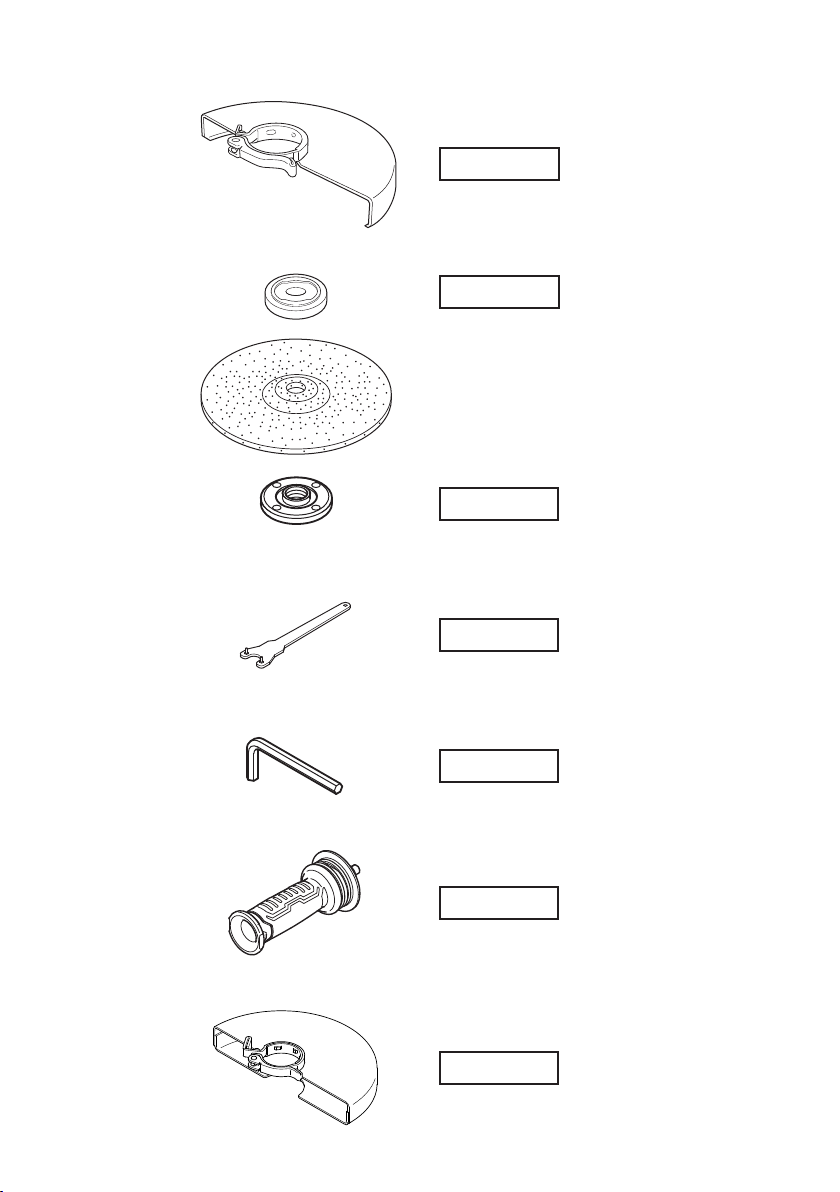
374311
374314
373779
3525491
944458
336865
374411
25
Page 26

26
Page 27

English Русский
1
Model No.
2
Serial No.
3
Date of Purchase
4
Customer Name and Address
5
Dealer Name and Address
(Please stamp dealer name and address)
Український
1
№ моделі
2
№ серії
3
Дата придбання
4
Ім’я і адреса клієнта
5
Ім’я і адреса дилера
(Будь ласка, поставте печатку з іменем і адресою дилера)
GUARANTEE CERTIFICATE
ГАРАНТІЙНИЙ СЕРТИФІКАТ
1
Модель №
2
Серийный №
3
Дата покупки
4
Название и адрес заказчика
5
Название и адрес дилера
(Пожалуйста, внесите название и адрес дилера)
1
2
3
ГАРАНТИЙНЫЙ СЕРТИФИКАТ
4
5
27
Page 28

English Русский
We declare under our sole responsibility that Disc Grinder, identifi ed
by type and specifi c identifi cation code *1), is in conformity with
all relevant requirements of the directives *2) and standards *3).
Technical fi le at *4) – See below.
The European Standard Manager at the representative offi ce in
Europe is authorized to compile the technical fi le.
The declaration is applicable to the product affi xed CE marking.
EC DECLARATION OF CONFORMITY
Мы с полной ответственностью заявляем, что угловая
шлифовальная машина, идентифицируемая по типу и
соответствующему идентификационному коду *1), отвечает
всем соответствующим требованиям директив *2) и стандартов
*3). Техническая документация в *4) – см. ниже.
Менеджер по европейским стандартам в представительстве в
Европе уполномочен составлять техническую документацию.
Данная декларация относится к изделиям, на которых имеется
маркировка CE.
Український
Ми заявляємо під нашу виключну відповідальність, що Кутова
шліфувальна машина, визначена за типом та унікальним
ідентифікаційним кодом *1), відповідає всім відповідним вимогам
директив *2) та стандартів *3). Технічна документацiя на *4) Див. нижче.
Відповідальний за дотримання європейських стандартів у
представництві в Європі уповноважений заповнювати технічний
паспорт.
Ця декларація дійсна щодо виробу,
*1) G23BYE C357149S
*2) 2006/42/EC, 2014/30/EU, 2011/65/EU
*3) EN60745-1:2009+A11:2010
*4)
ДЕКЛАРАЦІЯ ВІДПОВІДНОСТІ ЄС
маркованого СЕ.
EN60745-2-3:2011+A2:2013+A11:2014+A12:2014+A13:2015
EN55014-1:2006+A1:2009+A2:2011
EN55014-2:1997+A1:2001+A2:2008
EN61000-3-2:2014
EN61000-3-3:2013
Representative offi ce in Europe
Hikoki Power Tools Deutschland GmbH
Siemensring 34, 47877 Willich, Germany
Head offi ce in Japan
Koki Holdings Co., Ltd.
Shinagawa Intercity Tower A, 15-1, Konan 2-chome,
Minato-ku, Tokyo, Japan
ДЕКЛАРАЦИЯ СООТВЕТСТВИЯ EC
29. 12. 2018
Naoto Yamashiro
European Standard Manager
29. 12. 2018
A. Nakagawa
Corporate Offi cer
Hikoki Power Tools RUS L.L.C.
Kashirskoe Shosse 41, bldg. 2, 115409, Moscow, Russia
Tel: +7 495 727 4460
Fax: +7 495 727 4461
URL: http://www.hikoki-powertools.ru
Code No. C99733051 G
Printed in China
812
 Loading...