

Page 1
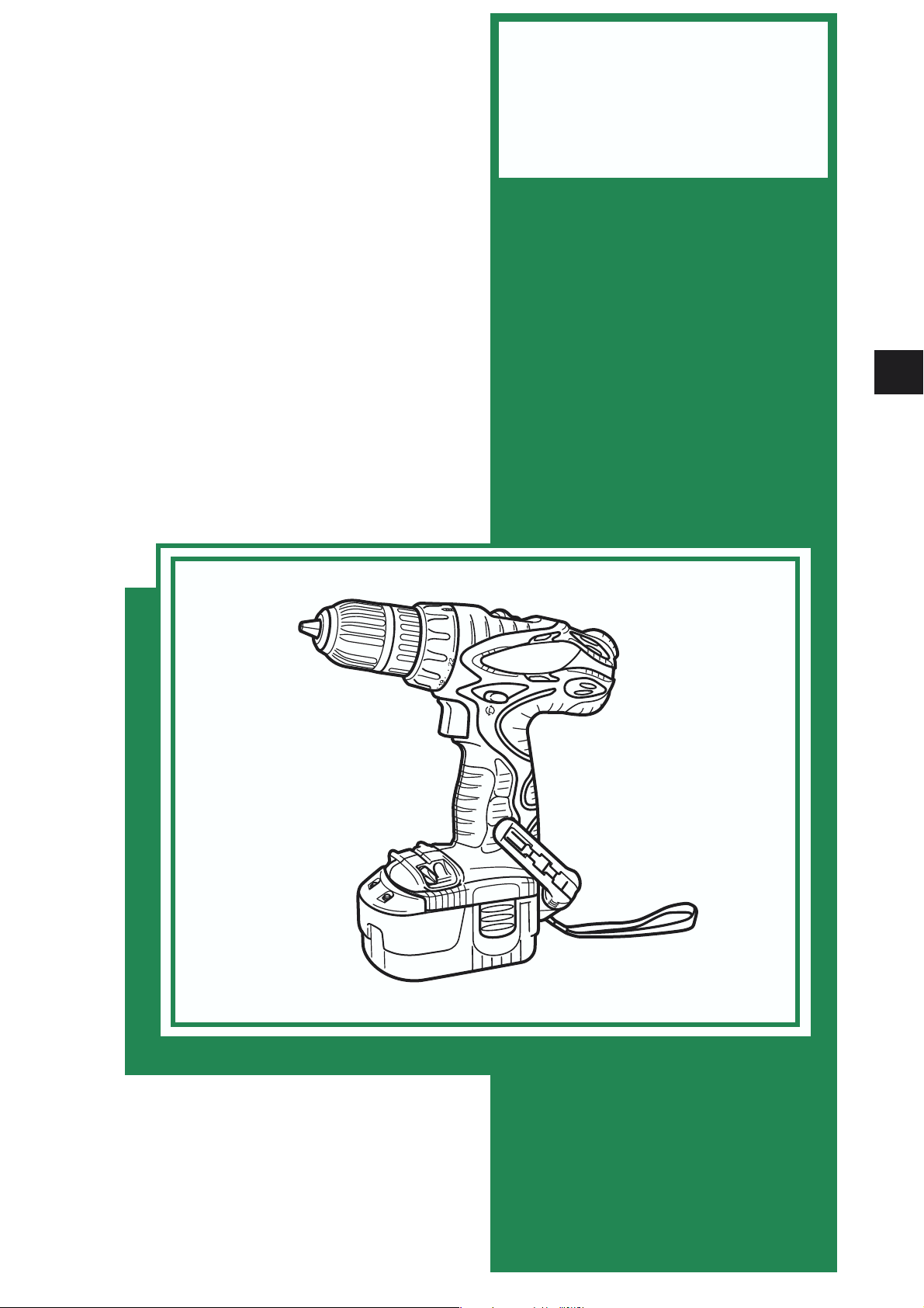
MODELS
DS 18DVF3
DS 14DVF3
CORDLESS DRIVER DRILL
DS 18DVF3
DS 14DVF3
Hitachi
Power Tools
TECHNICAL DATA
AND
SERVICE MANUAL
D
LIST Nos. DS 18DVF3: G823
DS 14DVF3: G822
SPECIFICATIONS AND PARTS ARE SUBJECT TO CHANGE FOR IMPROVEMENT
Apr. 2005
Page 2

REMARK:
Throughout this TECHNICAL DATA AND SERVICE MANUAL, a symbol(s)
is(are) used in the place of company name(s) and model name(s) of our
competitor(s). The symbol(s) utilized here is(are) as follows:
Competitors
Symbols Utilized
Company Name
Model Name
Q
B
C
DEWALT
BOSCH
MAKITA
DC759, DC728
32618, GSR14, 4V/32614
6228D
Page 3

CONTENTS
Page
1. PRODUCT NAME ................................................................................................................................ 1
2. MARKETING OBJECTIVE .................................................................................................................. 1
3. APPLICATIONS ................................................................................................................................... 1
4. SELLING POINTS ............................................................................................................................... 2
4-1. Selling Point Descriptions .....................................................................................................................3
5. SPECIFICATIONS ............................................................................................................................... 5
5-1. Model DS 18DVF3 ................................................................................................................................ 5
5-2. Model DS 14DVF3 ................................................................................................................................ 6
6. COMPARISONS WITH SIMILAR PRODUCTS ................................................................................... 7
6-1. Model DS 18DVF3 ................................................................................................................................ 7
6-2. Model DS 14DVF3 ................................................................................................................................ 9
7. WORKING PERFORMANCE PER SINGLE CHARGE ...................................................................... 11
7-1. Model DS 18DVF3 .............................................................................................................................. 11
7-2. Model DS 14DVF3 .............................................................................................................................. 12
8. PRECAUTIONS IN SALES PROMOTION ........................................................................................ 13
8-1. Safety Instructions .............................................................................................................................. 13
8-2. Inherent Drawbacks of Cordless Driver Drills Requiring Particular Attention
During Sales Promotion ......................................................................................................................16
9. REPAIR GUIDE ................................................................................................................................. 18
9-1. Precautions in Disassembly and Reassembly ....................................................................................18
9-2. Precautions in Disassembly and Reassembly of Battery Charger .....................................................25
10. STANDARD REPAIR TIME (UNIT) SCHEDULES .......................................................................... 26
Assembly Diagram for DV 18DVF3
Assembly Diagram for DV 14DVF3
Page 4

1. PRODUCT NAME
Hitachi 18 V Cordless Driver Drill, Model DS 18DVF3
Hitachi 14.4 V Cordless Driver Drill, Model DS 14DVF3
2. MARKETING OBJECTIVE
The new Models DS 18DVF3 and DS 14DVF3 are upgraded versions of the current DSxxDVF2 series cordless
driver drills highly reputed as reasonable professional-use cordless driver drills. These new models are added to
reinforce the excellent cost/performance cordless driver drill series including the Models DS 9DVF3 and
DS 12DVF3 released in advance.
The Model DS 14DVF3 (battery voltage 14.4 V) is higher-performance and more convenient thanks to the
powerful motor increased in size and the angle-adjustable one-touch hook as well as the same operability as the
current Model DS 14DVF2. In addition, the Model DS 14DVF3 is balanced best with the optimally designed
position of center of gravity for various applications.
The Model DS 18DVF3 (battery voltage 18 V) is most powerful in this series. The Model DS 18DVF3 is suitable
for heavy-load works that cannot be accomplished by the Model DS 14DVF3. Although the overall length of the
Model DS 18DVF3 is 10 mm longer than the Model DS 14DVF3 owing to adoption of the new 13-mm chuck, the
overall height is equivalent to the Model DS 14DVF3 thanks to the adoption of the flat battery.
Both the Models DS 18DVF3 and DS 14DVF3 are provided with convenient standard accessories such as spare
batteries, bit set and torchlight.
3. APPLICATIONS
Tightening and loosening wood screw, self-tapping screw and machine screw
Drilling into wood materials, plastic, mild steel and aluminum
--- 1 ---
Page 5
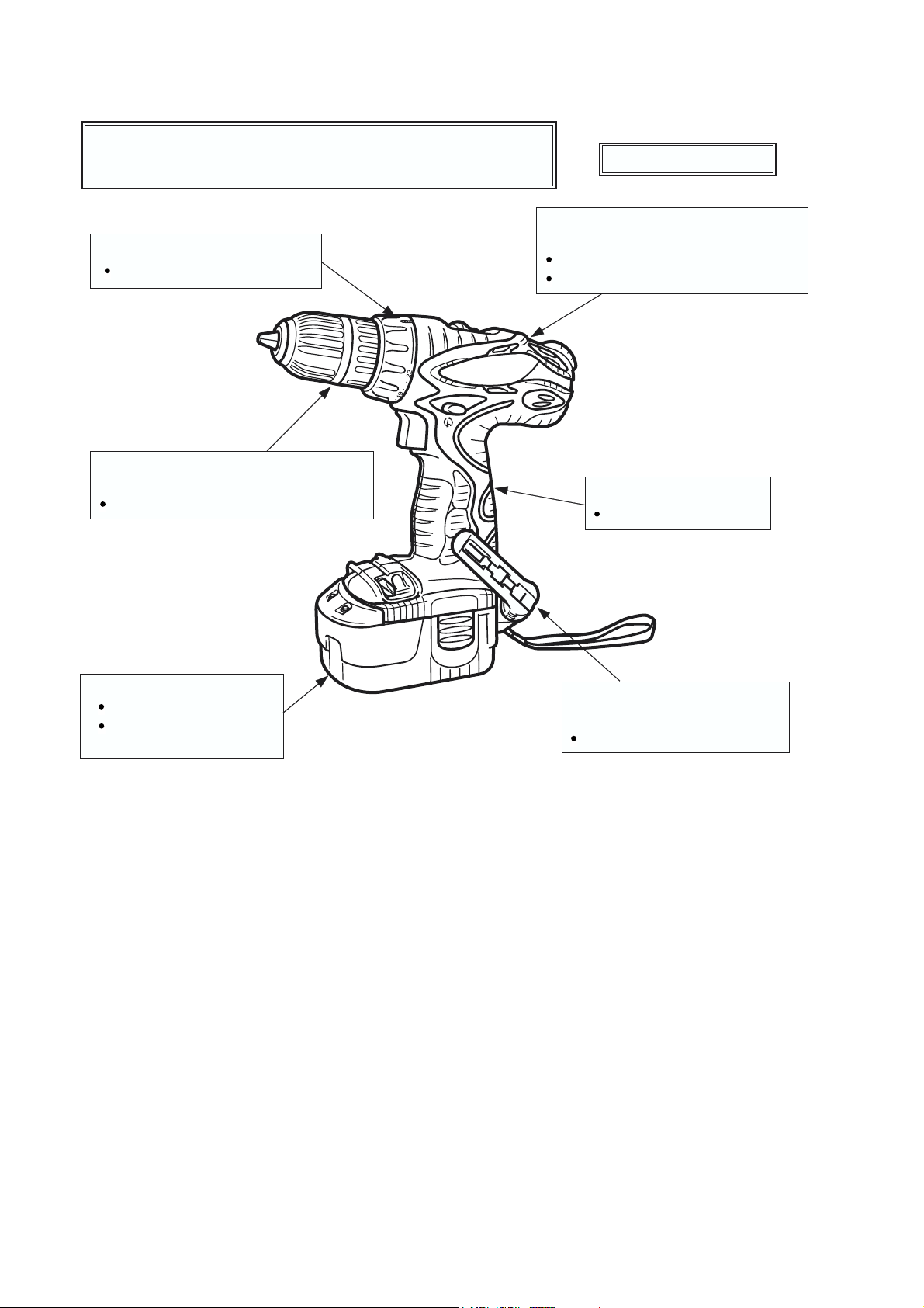
4. SELLING POINTS
Powerful and compact
Max. torque 45 N•m (DS 18DVF3) 34 N•m (DS 14DVF3)
Overall lengh 220 mm (DS 18DVF3) 210 mm (DS 14DVF3)
22-stage adjustable clutch
For precise torque setting
13 mm keyless chuck (DS 18DVF3)
10 mm keyless chuck (DS 14DVF3)
For tool-less bit changes
All new cyber design
Improved overload durability
(improved cooling efficiency)
Large diameter powerful unit motor
Optimally designed cooling air path
Soft grip handle
For increased comfort
Flat battery (DS 18DVF3)
Compact and stable
Interchangeable with
conventional batteries
5-position belt hook with
integrated bit holder
For convenient bit storage
[Model DS 18DVF3]
--- 2 ---
Page 6
4-1. Selling Point Descriptions
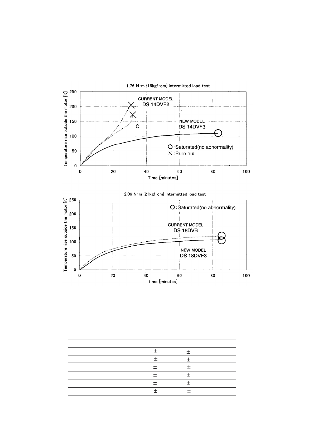
4-1-1. Improved overload durability (improved cooling efficiency)
The Model DS 14DVF3 ensures durability in continuous operation thanks to the powerful motor increased in size
and the improved air ducts. The Model DS 18DVF3 is equipped with the larger motor than the Model
DS 14DVF3. (See Fig. 1.)
Fig. 1 Curves of the motor temperature rise
4-1-2. 22-position torque adjustable clutch (Max. clutch torque 5.9 N•m)
The torque can be set finely thanks to the adoption of the 22 clutch positions to improve the operability (see
Table 1).
Table 1
Clutch dial position
1
4
10
13
19
22
5.9 1.0 N•m {60 10 kgf•cm}
Tightening torque
1.0 0.5 N•m {10 5 kgf•cm}
1.7 0.6 N•m {17 6 kgf•cm}
3.1 0.7 N•m {31 7 kgf•cm}
3.8 0.8 N•m {38 8 kgf•cm}
5.2 0.9 N•m {53 9 kgf•cm}
* There may be difference in operation depending on the screw shapes and workpieces.
Perform a test before actual driving.
--- 3 ---
Page 7

4-1-3. Soft grip handle
The handle is widely covered with soft-touch elastomer (rubber-like soft resin). It is slip-resistant and securely fits
in the palm of a hand even if the gripping hand sweats.
4-1-4. One-touch hook
(1) The hook can be quickly slid out whenever necessary and slid in when not necessary.
(2) The hook is mountable on either side using a flat-blade screwdriver or a coin.
(3) The angle of the hook is adjustable in five steps.
4-1-5. Flat battery (DS 18DVF3)
The battery is flat enough to stand the Model DS 18DVF3 upright stability. The conventional Hitachi 18 V
batteries are also usable.
--- 4 ---
Page 8
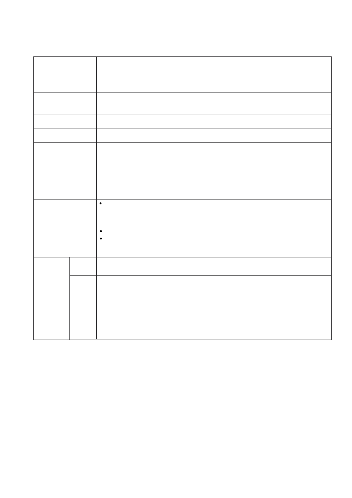
5. SPECIFICATIONS
5-1. Model DS 18DVF3
Capacity
Keyless chuck
(13VLRM-N)
Rotation speed (No-load)
Torque
Type of motor
Type of switch
Handle configuration
Enclosure
Battery
(Type EB 1814SL/
EB 1820L)
Charger
(Model UC 18YG)
Weight
Net
Gross
Standard
(2SLGX)
accessories
Screwdriver Machine screw
Wood screw
Drill Metal
••••••
••••••••
••••••••••••
6 mm (1/4")
8 dia. x 75 mm (#20 x 3")
Mild steel 13 mm (1/2") [Thickness 1.6 mm (1/16")]
Aluminum 13 mm (1/2") [Thickness 1.6 mm (1/16")]
••••••••••••••••••••••
Mount type
Diameter
•••••••••
Wood
••••••
Screw-on (UNF 1/2" --- 20)
2 --- 13 mm (5/64" --- 1/2")
38 mm (1-1/2") [Thickness 18 mm (11/16")]
Low: 0 --- 400/min, High: 0 --- 1,200/min
Slip torque
Max. torque
••••••••
1 --- 6 N•m (10 --- 60 kgf•cm, 9 --- 52 in-lbs.) [22 stages]
•••••••
Low: 45 N•m (459 kgf•cm, 400 in-lbs.), High: 11 N•m (112 kgf•cm, 97 in-lbs.)
Fan cooled DC magnet motor
Trigger switch with pushing button for forward and reverse rotation changeover (with brake)
T-type (with soft-grip handle)
••••••••
Body
Battery
Charger
Glassfiber reinforced polycarbonate resin (black) and thermoplastic elastomer (green)
•••••
Glassfiber reinforced polyamide resin (black)
•••
ABS resin (black)
Sealed cylindrical nickel-cadmium storage battery
Nominal voltage
Nominal life
Nominal capacity
•••••••••••••••
•••••••••••••••••••••
•••••••••••••
DC 18 V
Charging/discharging: Approx. 500 times
1.4/2.0 Ah
Overcharge prevention circuit:
A thermostat monitors the surface temperature of the battery and, on detecting the
temperature rise which occurs on completion of charging, automatically turns off the
unit to prevent the battery from overcharge.
Input capacity: 70 W
Indication method: Pilot lamp indicator of battery charging
Function: On
Off
Main body unit (including battery)
Charger unit (UC 18YG, including cord)
DS 18DVF3 (2SLGX)
Charger (UC 18YG)
Battery (EB 1814SL)
Phillips (plus) driver bit (No. 2)
Torchlight (Flashlight) (UB 18D)
Bit set
Case
•••••••••••••••••••••••••••••••••••••••••••••••••••••••••••••••••••••••••••••••••••••••••••••••••••••••••••••••
••••••••••••••••••••••••••••••••••••••••••••••••••••••••••••••••••••••••••••••••••••••••••••••••••••••••••••••••
••••••••••••••••••••••••••••••••••••••••••••••••••••••••••••
••••••••••••••••••••••••••••••••••••••••••••••••••••••••••••
••••••••••••••••••••••••••••••••••••••••••••••••••••
•••••••••••••••••••••••••••••••••••••••••••
••••••••••••••••••••••••••••••••••••••••••••••••••••••••••••••••••••••
During charging
Charging completed
2.0 kg (4.4 Ibs.)
0.3 kg (0.7 Ibs.)
5.6 kg (12.4 Ibs.)
••••••••••••••••••••••••••••••••••••••••••••••••••••••••••••••• •••••••••••••••••••••••••••
•••••••••••••••••••••••••••••••••••••••••••••••••••••••••••••••••••••••••••••••••••••••••
••••••••••••••••••••••••••••••••••••••••••••••••••••••••••••••••••••••••••••
••••••••••••••••••••••••••••••••••••••••••••••••••••••••••••••••••••••••••
1
2
1
1
1
1
--- 5 ---
Page 9
5-2. Model DS 14DVF3
Capacity
Keyless chuck
(10VLRF-N)
Rotation speed (No-load)
Torque
Type of motor
Type of switch
Handle configuration
Enclosure
Battery
(Type EB 1414S)
Charger
(Model UC 18YG)
Weight
Net
Gross
Standard
(2SGX)
accessories
(3SGK)
Screwdriver Machine screw
Wood screw
Drill Metal
••••••
••••••••
••••••••••••
6 mm (1/4")
6.2 dia. x 63 mm (#14 x 2-1/2")
Mild steel 12 mm (15/32") [Thickness 1.6 mm (1/16")]
Aluminum 15 mm (19/32") [Thickness 1.6 mm (1/16")]
••••••••••••••••••••••
Mount type
Diameter
•••••••••
Wood
••••••
Screw-on (UNF 1/2" --- 20)
0.8 --- 10 mm (1/32" --- 3/8")
30 mm (1-3/16") [Thickness 18 mm (11/16")]
Low: 0 --- 400/min, High: 0 --- 1,200/min
Slip torque
Max. torque
••••••••
1 --- 5.9 N•m (10 --- 60 kgf•cm, 9 --- 52 in-lbs.) [22 stages]
•••••••
Low: 34 N•m (347 kgf•cm, 300 in-lbs.) High: 8 N•m (82 kgf•cm, 71 in-lbs.)
Fan cooled DC magnet motor
Trigger switch with pushing button for forward and reverse rotation changeover (with brake)
T-type (with soft-grip handle)
•••••••
Body
Battery
Glassfiber reinforced polycarbonate resin (black) and thermoplastic elastomer (green)
••••
Glassfiber reinforced polyamide resin (black)
Charger •• ABS resin (black)
Sealed cylindrical nickel-cadmium storage battery
Nominal voltage
Nominal life
Nominal capacity
•••••••••••••••
•••••••••••••••••••••
•••••••••••••
DC 14.4 V
Charging/discharging: Approx. 500 times
1.4 Ah
Overcharge prevention circuit:
A thermostat monitors the surface temperature of the battery and, on detecting the
temperature rise which occurs on completion of charging, automatically turns off the
unit to prevent the battery from overcharge.
Input capacity: 70 W
Indication method: Pilot lamp indicator of battery charging
Function: On
Main body unit (including battery)
Charger unit (UC 18YG, including cord)
DS 14DVF3 (2SGX)
DS 14DVF3 (3SGX)
Charger (UC 18YG)
Battery (EB 1414S)
Phillips (plus) driver bit (No. 2)
Torchlight (Flashlight) (UB 18D)
Bit set
Case
•••••••••••••••••••••••••••••••••••••••••••••••••••••••••••••••••••••••••••••••••••••••••••••••••••••••••••••••
•••••••••••••••••••••••••••••••••••••••••••••••••••••••••••••••••••••••••••••••••••••••••••••••••••••••••••••••••
Charger (UC 18YG)
Battery (EB 1414S)
Phillips (plus) driver bit (No. 2)
Bit set
Case
•••••••••••••••••••••••••••••••••••••••••••••••••••••••••••••••••••••••••••••••••••••••••••••••••••••••••••••••
•••••••••••••••••••••••••••••••••••••••••••••••••••••••••••••••••••••••••••••••••••••••••••••••••••••••••••••••••
••••••••••••••••••••••••••••••••••••••••••••••••••••••••••••
••••••••••••••••••••••••••••••••••••••••••••••••••••••••••••
Off
••••••••••••••••••••••••••••••••••••••••••••••••••••
•••••••••••••••••••••••••••••••••••••••••••
•••••••••••••••••••••••••••••••••••••••••••••••••••••••••••••••••••••••
•••••••••••••••••••••••••••••••••••••••••••••••••••••••••••••••••••••••
••••••••••••••••••••••••••••••••••••••••••••••••••••••••••••••• ••••••••••••••••••••••••••••
••••••••••••••••••••••••••••••••••••••••••••••••••••••••••••••••••••••••••••••••••••••••••••
••••••••••••••••••••••••••••••••••••••••••••••••••••••••••••••••••••••••••••
••••••••••••••••••••••••••••••••••••••••••••••••••••••••••••••••••••••••••
••••••••••••••••••••••••••••••••••••••••••••••••••••••••••••••• ••••••••••••••••••••••••••••
••••••••••••••••••••••••••••••••••••••••••••••••••••••••••••••••••••••••••••••••••••••••••••
••••••••••••••••••••••••••••••••••••••••••••••••••••••••••••••••••••••••••••
During charging
Charging completed
1.8 kg (4.0 Ibs.)
0.3 kg (0.7 Ibs.)
4.9 kg (10.8 Ibs.)
5.2 kg (11.5 Ibs.)
1
2
1
1
1
1
1
3
1
1
1
--- 6 ---
Page 10

6. COMPARISONS WITH SIMILAR PRODUCTS
6-1. Model DS 18DVF3
Maker
Model
Machine screw
Screw
driving
Wood screw
Mild steel
Drilling
Max. capacity
Aluminum
Soft wood
Rotation
speed
Low
High
Slip torque
Max. torque
Max. torque (hard)
(actually measured value)
Drill chuck
Type
Capacity
HITACHI
DS 18DVF3
6 mm (1/4")
8 mm dia. x 75 mm
(#20 x 3")
13 mm (1/2")
13 mm (1/2")
38 mm (1-1/2")
0 --- 400/min
0 --- 1,200/min
1.0 --- 5.9 N•m
(10 --- 60 kgf•cm)
(9 --- 52 in-lbs.)
[22 positions]
45 N•m
(459 kgf•cm)
(400 in-lbs.)
57 N•m
(585 kgf•cm)
(508 in-lbs.)
Double sleeve
13 mm (1/2")
DS 18DVB (USA)
6 mm (1/4")
8 mm dia. x 75 mm
(#20 x 3")
10 mm (3/8")
10 mm (3/8")
25 mm (1")
0 --- 400/min
0 --- 1,400/min
1.0 --- 5.9 N•m
(10 --- 60 kgf•cm)
(9 --- 52 in-lbs.)
[22 positions]
45 N•m
(459 kgf•cm)
(400 in-lbs.)
61 N•m
(630 kgf•cm)
(550 in-lbs.)
Double sleeve
10 mm (3/8")
Q (EURO)
Not indicated
Not indicated
13 mm (1/2")
Not indicated
38 mm (1-1/2")
0 --- 400/min
0 --- 1,400/min
Not indicated
[17 positions]
44 N•m
(449 kgf•cm)
Can not measure
(Slip)
Single sleeve
13 mm (1/2")
Q (U.S.A.)
Not indicated
Not indicated
13 mm (1/2")
Not indicated
38 mm (1-1/2")
0 --- 400/min
0 --- 1,500/min
Not indicated
[17 positions]
450 in-lbs.
(518 kgf•cm)
Can not measure
(Slip)
Single sleeve
13 mm (1/2")
Switch
Type
Feedback circuit
Variable speed
Equipped
Variable speed
Equipped
Variable speed
Equipped
Electric brake Equipped Equipped Equipped
Automatic spindle lock None None Equipped
Reversing switch Push-button Push-button Push-button
Handle shape T-type
Soft-grip handle
Belt hook
Equipped
Equipped Equipped
T-type T-type T-type
Equipped Equipped
None
Strap Equipped Equipped None
Battery
Dimensions
Weight
Remarks*
Nominal capacity
Nominal voltage
Charging time*
Overall length
Overall height
Overall width
••••••••
Charging time varies depending on the type of charger to be used.
1.4/2.0 Ah
18 V
30/50 min.
220 mm (8-21/32")
233 mm (9-11/64")
76 mm (3")
2.0 kg (4.4 lbs.)
1.2 Ah
18 V
60 min.
232 mm (9-9/64")
257 mm (10-1/8")
76 mm (3")
2.0 kg (4.4 lbs.)
2.0 Ah
18 V
60 min.
230 mm (9-1/16")
239 mm (9-13/32")
90 mm (3-35/64")
2.4 kg (5.2 lbs.)
Variable speed
Equipped
Equipped
Equipped
Push-button
Equipped
None
None
1.7 Ah
18 V
45 min.
230 mm (9-1/16")
239 mm (9-13/32")
90 mm (3-35/64")
2.4 kg (5.2 lbs.)
--- 7 ---
Page 11

Maker
Model
B
Screw
Machine screw
driving
Wood screw
Mild steel
Drilling
Max. capacity
Aluminum
Soft wood
Rotation
speed
Low
High
Slip torque
Max. torque
Max. torque (hard)
(actually measured value)
Drill chuck
Type
Capacity
Not indicated
6.8 mm dia. x 76 mm
(#16 x 3")
13 mm (1/2")
Not indicated
50 mm (2")
0 --- 400/min
0 --- 1,300/min
Not indicated
[15 stages]
310 in-lbs.
(357 kgf•cm)
Can not measure
(Slip)
Single sleeve
10 mm (3/8")
Switch
Type
Feedback circuit
Variable speed
Equipped
Electric brake Equipped
Automatic spindle lock Equipped
Reversing switch Push-button
Handle shape T-type
Soft-grip handle
Belt hook
Equipped
None
Strap None
Battery
Dimensions
Weight
Remarks*
Nominal capacity
Nominal voltage
Charging time*
Overall length
Overall height
Overall width
••••••••
Charging time varies depending on the type of charger to be used.
2.0 Ah
18 V
60 min.
220 mm (8-21/32")
257 mm (10-1/8")
87 mm (3-27/64")
2.0 kg (4.5 lbs.)
--- 8 ---
Page 12

6-2. Model DS 14DVF3
Maker
Model
Machine screw
Screw
driving
Wood screw
Mild steel
Drilling
Max. capacity
Aluminum
Soft wood
Rotation
speed
Low
High
Slip torque
Max. torque
Max. torque (hard)
(actually measured value)
Drill chuck
Type
Capacity
HITACHI
DS 14DVF3
6 mm (1/4")
6.2 mm dia. x 63 mm
(#14 x 2-1/2")
12 mm (15/32")
15 mm (19/32")
30 mm (1-3/16")
0 --- 400/min
0 --- 1,200/min
1 --- 6 N•m
(10 --- 60 kgf•cm)
(9 --- 52 in-lbs.)
[22 positions]
34 N•m
(347 kgf•cm)
(300 in-lbs.)
54 N•m
(546 kgf•cm)
(475 in-lbs.)
Double sleeve
10 mm (3/8")
DS 14DVF2
6 mm (1/4")
5.5 mm dia. x 63 mm
(#12 x 2-1/2")
12 mm (15/32")
15 mm (19/32")
25 mm (1")
0 --- 400/min
0 --- 1,200/min
1.0 --- 5.9 N•m
(10 --- 60 kgf•cm)
(9 --- 52 in-lbs.)
[22 positions]
30 N•m
(306 kgf•cm)
(213 in-lbs.)
40 N•m
(410 kgf•cm)
(356 in-lbs.)
Double sleeve
10 mm (3/8")
C
6 mm (1/4")
5.1 mm dia. x 63 mm
(3/16" x 2-1/2")
10 mm (3/8")
Not indicated
24 mm (15/16")
0 --- 350/min
0 --- 1,100/min
Not indicated
[16 positions]
22 N•m
(224 kgf•cm)
(200 in-lbs.)
31 N•m
(319 kgf•cm)
(277 in-lbs.)
Double sleeve
10 mm (3/8")
Switch
Type
Feedback circuit
Variable speed
Equipped
Variable speed
Equipped
Variable speed
Equipped
Electric brake Equipped Equipped Equipped
Automatic spindle lock None None None
Reversing switch Push-button Push-button Push-button
Handle shape
Soft-grip handle
Belt hook
T-type
Equipped
Equipped None
T-type T-type
Equipped None
None
Strap Equipped Equipped None
Battery
Dimensions
Weight
Remarks*
Nominal capacity
Nominal voltage
Charging time*
Overall length
Overall height
Overall width
••••••••
Charging time varies depending on the type of charger to be used.
1.4 Ah
14.4 V
30 min.
210 mm (8-17/64")
229 mm (9")
76 mm (3")
1.8 kg (4.0 lbs.)
1.4 Ah
14.4 V
60 min.
210 mm (8-17/64")
241 mm (9-1/2")
76 mm (3")
1.7 kg (3.7 lbs.)
1.3 Ah
14.4 V
30 min.
210 mm (8-17/64")
249 mm (9-51/64")
95 mm (3-47/64")
1.7 kg (3.7 lbs.)
--- 9 ---
Page 13

Maker
Model
Q (EURO)
Q (U.S.A.)
B (EURO)
B (U.S.A.)
Machine screw
Not indicated
Not indicated
Not indicated
Screw
driving
Wood screw
Mild steel
Drilling
Max. capacity
Aluminum
Soft wood
Rotation
speed
Low
High
Slip torque
Max. torque
Max. torque (hard)
(actually measured value)
Drill chuck
Type
Capacity
Type
Switch
Feedback circuit
Not indicated
10 mm (3/8")
Not indicated
32 mm
0 --- 400/min
0 --- 1,400/min
Not indicated
[17 positions]
35 N•m
(357 kgf•cm)
58.3 N•m
(594 kgf•cm)
Single sleeve
10 mm (3/8")
Variable speed
Equipped
Not indicated
10 mm (3/8")
Not indicated
38 mm (1-1/2")
0 --- 400/min
0 --- 1,400/min
Not indicated
[17 positions]
400 in-lbs.
(357 kgf•cm)
516 N•m
(594 kgf•cm)
Single sleeve
13 mm (1/2")
Variable speed
Equipped
8 mm dia.
11 mm
Not indicated
32 mm
0 --- 400/min
0 --- 1,200/min
1 --- 8 N•m
(10 --- 82 kgf•cm)
[15 stages]
35 N•m
(357 kgf•cm)
Can not measure
(Break down)
Single sleeve
10 mm (3/8")
Variable speed
Equipped
Electric brake Equipped Equipped Equipped
Automatic spindle lock Equipped Equipped Equipped
Not indicated
#16 x 3"
(6.8 x 76 mm)
13 mm (1/2")
Not indicated
51 mm (2")
0 --- 400/min
0 --- 1,200/min
Not indicated
[15 stages]
300 in-lbs.
(336 kgf•cm)
Can not measure
(Break down)
Single sleeve
10 mm (3/8")
Variable speed
Equipped
Equipped
Equipped
Reversing switch Push-button Push-button Push-button
Handle shape
Soft-grip handle
Belt hook
T-type
Equipped
None None
T-type T-type T-type
Equipped Equipped
None None
Strap None None None
Battery
Dimensions
Weight
Remarks*
Nominal capacity
Nominal voltage
Charging time*
Overall length
Overall height
Overall width
••••••••
Charging time varies depending on the type of charger to be used.
1.3 Ah
14.4 V
60 min.
220 mm (8-21/32")
230 mm (9-1/16")
84 mm (3-5/16")
1.9 kg (4.3 lbs.)
1.7 Ah
14.4 V
45 min.
230 mm (9-1/16")
230 mm (9-1/16")
84 mm (3-5/16")
2.2 kg (4.8 lbs.)
1.5 Ah
14.4 V
60 min.
220 mm (8-21/32")
255 mm (10-3/64")
86 mm (3-25/64")
1.8 kg (4.0 lbs.)
Push-button
Equipped
None
2.0 Ah
14.4 V
60 min.
220 mm (8-21/32")
255 mm (10-3/64")
86 mm (3-25/64")
1.9 kg (4.3 lbs.)
--- 10 ---
Page 14

7. WORKING PERFORMANCE PER SINGLE CHARGE
7-1. Model DS 18DVF3
Drilling and fastening performance comparison per charge
Type of work
Maker
Model
*300
*0
50
0
Working capacity (*1)
*600
100
*900
150
*1200
200
*1500
250
Driling
speed
(sec./pc.)
< Low speed >
< High speed >
L75 mm (3")
HITACHI
HITACHI
HITACHI
DS 18DVF3
DS 18DVB
Q
B
DS 18DVF3
DS 18DVB
Q
B
DS 18DVF3
DS 18DVB
65 (90)
35 (50)
35
80 (115)
65
115
115
60
95
75
4.7
5.3
5.3
5.2
11
12
11
13
5.9
6.1
Q
with pilot hole
< Low speed >
B
DS 18DVF3
HITACHI
DS 18DVB
Q
B
< High speed >
Remark*: Number of machine screws fastened per charge
Remark*1: Number of holes or fasteners per charge
The above table shows an example of test data. The batteries used in this test are as follows:
Model DS 18DVF3: 1.4 Ah
Model DS 18DVB: 1.2 Ah
Q, B: 2.0 Ah
The figures in parentheses ( ) indicate the values for a 2.0 Ah battery.
As actually measured values listed in the above table may vary depending on sharpness of the drill bit, workpiece hardness (particularly in
wood materials), moisture content of wood, charging condition, operator skill, etc.
This data should be used as a comparative guide only.
65
50
* 650 (930)
* 540
* 810
* 750
5.4
5.8
0.9
0.9
0.9
1.0
--- 11 ---
Page 15

7-2. Model DS 14DVF3
Drilling and fastening performance comparison per charge
Type of work
Maker
Model
*0
0
Working capacity (*1)
*300
50
*600
100
*900
150
*1200
200
*1500
250
Driling
speed
(sec./pc.)
18 mm dia. (11/16")
6.5 mm dia. (1/4")
L63 mm (2-1/2")
< Low speed >
< High speed >
HITACHI
HITACHI
HITACHI
DS 14DVF3
DS 14DVF2
C
Q
B
DS 14DVF3
DS 14DVF2
C
Q
B
DS 14DVF3
DS 14DVF2
50
50
55
55
60
80
80
110
115
130
130
170
4.4
4.8
7.0
5.6
6.3
12
13
15
11
14
4.4
5.0
C
6.2 mm dia. (#14)
with pilot hole
Q
B
< Low speed >
DS 14DVF3
HITACHI
DS 14DVF2
C
Q
B
< High speed >
Remark*: Number of machine screws fastened per charge
Remark*1: Number of holes or fasteners per charge
The above table shows an example of test data. The batteries used in this test are as follows:
Models DS 14DVF3, DS 14DVF2: 1.4 Ah
C, Q: 1.3 Ah
B: 1.5 Ah
As actually measured values listed in the above table may vary depending on sharpness of the drill bit, workpiece hardness (particularly in
wood materials), moisture content of wood, charging condition, operator skill, etc.
This data should be used as a comparative guide only.
70
70
75
* 610
* 570
* 920
* 380
* 530
6.3
7.5
5.4
1.0
1.0
1.2
0.9
1.0
--- 12 ---
Page 16

8. PRECAUTIONS IN SALES PROMOTION
8-1. Safety Instructions
In the interest of promoting the safest and most efficient use of the Models DS 18DVF3 and DS 14DVF3 Cordless
Driver Drills by all of our customers, it is very important that at the time of sale, the salesperson carefully ensures
that the buyer seriously recognizes the importance of the contents of the Handling Instructions, and fully
understands the meaning of the precautions listed on the Caution Plate and Name Plate attached to each tool.
A. Handling instructions
Salespersons must be thoroughly familiar with the contents of the Handling Instructions in order to give pertinent
advice to the customer. In particular, they must have a thorough understanding of the precautions for use of the
cordless tools which are different from those of ordinary electric power tools.
(1) Before use, ensure that the unit is fully charged.
New units are not fully charged. Even if the units were fully charged at the factory, long periods of inactivity,
such as during shipping, cause the storage battery to lose its charge. Customers must be instructed to fully
charge the unit prior to use.
(2) Connect the Charger to an AC power outlet only.
Use of any other power source (DC outlet, fuel powered generator, etc.) will cause the Charger to overheat
and burn out.
(3) Do not use any voltage increasing equipment (transformer etc.) between the power source and the Charger.
If the Charger is used with voltage higher than that indicated on the unit, it will not function properly.
(4) Conduct battery charging at an ambient temperature range of 10 ûC --- 40 ûC (50 ûF --- 104 ûF).
Special temperature sensitive devices are employed in the Charger to permit rapid charging. Ensure that
customers are instructed to use the Charger at the indicated ambient temperature range. At temperature
under 10 ûC (50 ûF) the thermostat will not function properly, and the storage battery may be overcharged.
At temperature over 40 ûC (104 ûF), the storage battery cannot be sufficiently charged. The optimum
temperature range is 20 ûC --- 25 ûC (68 ûF --- 77 ûF).
(5) The battery charger should not be used continuously.
At high ambient temperature, if over three storage batteries are charged in succession, the temperature of the
coils on the transformer will rise and there is a chance that the temperature fuse inserted in the interior of the
transformer will inadvertently melt. After charging one battery, please wait about 15 minutes before charging
the next battery.
(6) Do not insert foreign objects into the air vents on the Charger.
The Charger case is equipped with air vents to protect the internal electronic components from overheating.
Caution the customer not to allow foreign materials, such as metallic or flammable objects, to be dropped or
inserted into the air vents. This could cause electrical shock, fire, or other serious hazards.
--- 13 ---
Page 17

(7) Do not attempt to disassemble the Storage Battery or the Charger.
Special devices, such as a thermostat, are built into the storage battery and charger to permit rapid charging.
Incorrect parts replacement and/or wiring will cause malfunctions which could result in fire or other hazards.
Instruct the customer to bring these units to an authorized service center in the event repair or replacement is
necessary.
(8) Disposal of the Storage Batteries
Ensure that all customers understand that the Storage Batteries should be returned to the Hitachi power tool
sales outlet or the authorized service center when they are no longer capable of being recharged or repaired.
If thrown into a fire, the batteries may explode, or, if discarded indiscriminately, leakage of the cadmium
compound contained in the battery may cause environmental pollution.
B. Caution plates
(1) The following cautions are listed on the Name Plate attached to the main body of each tool.
For the U.S.A. and Canada
Warning
• To reduce the risk of injury, user must read and understand
Instruction Manual.
AVERTISSEMENT
• Afin de reduire le risque de blessures, I'utilisateur doit lire
et bien comprendre le mode d'emploi.
(2) The following cautions are listed on the Name Plate attached to each Storage Battery.
For Europe
CAUTION
• Read thoroughly HANDLING INSTRUCTIONS before use.
• Do not disassemble nor throw into fire.
For the U.S.A. and Canada
CAUTION
• For safe operation, see Instruction Manual.
• Use HITACHI charger recommended in instruction manual
for recharging.
--- 14 ---
Page 18

(3) The following caution is listed on the Name Plate to the Model UC 18YG Charger.
For the U.S.A. and Canada
CAUTION
series. Other types of batteries may burst causing personal injury and damage.
Charge between 32ûF and 104ûF. Rest 15 minutes between the charging of
batteries. Indoor use only. Replace defective cord immediately.
For safe operation, see instruction manual. Charge HITACHI
rechargeable batteries types EB7, EB9, EB12, EB14 and EB18
--- 15 ---
Page 19

8-2. Inherent Drawbacks of Cordless Driver Drills Requiring Particular Attention During Sales Promotion
The cordless driver drill offers many advantages; it can be used in places where no power source is available, the
absence of a cord allows easy use, etc. However, any cordless tool has certain inherent drawbacks.
Salespersons must be thoroughly familiar with these drawbacks in order to properly advise the customer in the
most efficient use of the tool.
A. Suggestions and precautions for the efficient use of the tool
(1) Use the Cordless Driver Drill for comparatively light work.
Because they are battery driven, the output of the motor in cordless driver drills is rather low in comparison
with conventional electric power tools. Accordingly, they are not suitable for continuous drilling of many holes
in succession, or for drilling into particularly hard materials which creates a heavy load. Salespersons should
recommend conventional electric power tools for such heavy work.
(2) Drilling of large diameter holes should be conducted at low speed.
Instruct the customer that drilling of large diameter holes or other work which requires particularly strong
torque should be done at low speed. Because there is less torque at high speed, attempting such work at high
speed will not improve working efficiency.
(3) Do not insert a foreign object into body vent holes.
The body of this tool has vent holes for improving the cooling efficiency. As a fan is built into the motor, a
foreign object inserted through a vent hole may cause a failure. Please instruct customers to never insert a
foreign object into the vent hole.
(4) Avoid "Locking" of the motor.
Locking of the motor will cause an overload current that could result in burning of the motor and/or rapid
deterioration of the battery. Salespersons should advise the customer to immediately release the switch and
stop operation if the motor becomes locked. (A jammed drill bit can be disengaged from the workpiece
material by setting the switch to reverse rotation, or by manually turning the main body of the tool.)
(5) Variation in amount of work possible per charge
Although the nominal chargeable capacity of the storage batteries used with the Model DS 18DVF3 and
DS 14DVF3 is 1.4 Ah or 2.0 Ah, the actual capacity may vary within 10% of that value depending on the
ambient temperature during use and charging, and the number of times the batteries have been recharged.
It should be noted that other factors which may have a bearing on the amount of work possible per charge are
the working conditions (ambient temperature, type and moisture content of the workpiece, sharpness of the
drill bit, etc.) and the operational skill of the user.
--- 16 ---
Page 20

(6) Precautions in the use of HSS Drill Bits
For example, although the Model DS 18DVF3 is designed for drilling capacities of 38 mm (1-1/2") in wood, and
13 mm (1/2") in aluminum and mild steel, this capability is not as efficient as conventional electric power tools.
In particular, when drilling through aluminum material with a 13 mm (1/2") drill bit, the drill tends to become
locked when the drill bit penetrates through the material. For this reason, the customer should be cautioned to
reduce the thrust on the main body of the drill when drilling completely through the material to avoid locking
the tool. Repeated locking of the drill causes excessive current flow from the batteries which not only
decreases the amount of work possible per charge, but could also result in burning of the motor.
(7) Securely tighten the sleeve of the keyless chuck.
The keyless chuck may slip during operation if the shape of the drill bit shank is cylindrical depending on the
surface conditions, materials, etc. Please instruct the customers to retighten the keyless chuck more securely
if the keyless chuck slips during operation. The holding force of the keyless chuck is increased as the
tightening force of the keyless chuck is increased.
(8) Avoid continuous use.
Although the Models DS 18DVF3 and DS 14DVF3 can bear continuous operation under certain conditions,
operating conditions are different depending on material of workpiece and sharpness of the drill bit in use.
Please instruct the customers to avoid continuous use of the Models DS 18DVF3 and DS 14DVF3 and take a
pause about 15 minutes after a single charge operation as a guide.
--- 17 ---
Page 21

9. REPAIR GUIDE
Be sure to remove the storage batteries from the main body before servicing. Inadvertent triggering of the switch
with the storage battery connected will result in danger of accidental turning of the motor.
9-1. Precautions in Disassembly and Reassembly
The [Bold] and <Bold> numbers in the descriptions below correspond to the item numbers in the Parts List and
exploded assembly diagram. ([Bold]: DS 18DVF3, <Bold>: DS 14DVF3)
9-1-1. Disassembly
(1) Removal of the Hook Ass'y [37] <38>
Remove Special Screw (A) M5 [42] <43> with a flat-blade screwdriver or a coin. Remove the Hook Ass'y
[37] <38> and the Hook Spring [41] <42>.
(2) Removal of Housing (A). (B) Set [29] <30>
First, align the drill mark " " at the Clutch Dial [4] <4> with the triangle mark at Housing (A). (B) Set [29]
<30>. Remove the eight Tapping Screws (W/Flange) D3 x 16 (Black) [26] <27> secured to the main body.
Gently open housing (A) and housing (B) while holding their battery loading sections.
(3) After housing (B) has been removed, all the internal parts, assembled or separate, can be taken out as they
are. Lift the entire contents from housing (A) while holding the Motor [25] <25> and the Clutch Dial [4] <4>.
(4) Removal of the Drill Chuck [2] <2> (See Fig. 2.)
(a) Turn the Motor [25] <25> counterclockwise (when viewed from the rear) and remove it from the Rear Case
[14] <14>. Remove the Shift Knob [35] <36> from the Shift Arm [16] <16>. Take care not to remove the
Shift Arm [16] <16> from the Rear Case [14] <14> in this operation.
(b) Attach the motor spacer (an accessory of the special repair tool J-342, Code No. 324-582) to the assembly
of the Drill Chuck [2] <2>, Clutch Dial [4] <4>, Front Case [9] <9> and Rear Case [14] <14> then mount it
in special repair tool J-342 clamped in the vise as illustrated in Fig. 2. In this operation, check that the
pinion press-fitted in the special repair tool J-342 and Planet Gear (A) Set [21] <21> are engaged properly.
(c) Secure the Slide Ring Gear [17] to the Front Case [9] <9> side with the Shift Arm [16] <16>.
(d) Turn the sleeve of the Drill Chuck [2] <2> counterclockwise (when viewed from the front) to fully open the
jaws of the Drill Chuck [2] <2>. Turn the Special Screw (Left Hand) M6 x 23 [1] <1> clockwise and remove
it. (Note that the special screw is left-hand threaded.)
(e) Fit the hexagonal bar wrench M10 into the Drill Chuck [2] <2> as illustrated in Fig. 2 and remove the Drill
Chuck [2] <2> by turning the hexagonal bar wrench counterclockwise.
--- 18 ---
Page 22

Fig. 2
(5) Disassembly of the gear unit
Remove the Shift Arm [16] <16> from the Rear Case [14] <14>,
then remove the Screw Set D3 x 12 (4 pcs.) [15] <15>
connecting the Front Case [9] <9> and the Rear Case [14] <14>.
Remove Washer (A) [13] <13>, Planet Gear (C) Set (3 pcs.) [12]
<12>, Ring Gear [11] <11>, six Steel Balls D5 [10] <10> from the
Front Case [9] <9> in order. Take care not to lose the six Steel
Balls D5 [10] <10> in this operation.
(6) Disassembly of the clutch unit
(a) After press up the hook of Front Case [9] <9> with the small flat-blade screwdriver, the Clutch Dial [4] <4>
and the Click Spring [5] <5> can be taken out as they are. (See Fig. 3.)
(b) Turn the Nut [6] <6> counterclockwise and remove it from the Front Case [9] <9>, then remove the Spring
[7] <7> and Washer (D) [8] <8> from the Front Case [9] <9>.
Hook (3 pcs.)
Fig. 3
NOTE: Do not remove the Front Case [9] <9>.
(7) Disassembly of the power supply unit
NOTE: Do not remove the heat sink secured to the DC-Speed Control Switch [32] <33> with a screw.
Remove the two Machine Screws (W/Sp. Washer) M4 x 6 [28] <29>, and take the Motor [25] <25> and the
Motor Spacer [24] <24> apart. Disconnect the Internal Wires [30] [31] <31> <32> from the Motor [25] <25>
with a soldering iron, then disconnect them from the DC-Speed Control Switch [32] <33> with a soldering iron
in the same manner.
--- 19 ---
Page 23

9-1-2. Reassembly
Reassembly can generally be carried out as the reverse of the disassembly procedure, with some items to be
noted as follows.
(1) Reassembly of the power supply unit
(a) Perform wiring according to the wiring diagram (Fig. 4).
Motor Spacer [24] <24>
Machine Screw
(W/Sp. Washer) M4 x 6
[28] <29>
Ferrite Core [34] <35>
Internal Wire (Red)
[31] <32>
Internal Wire (Black)
[30] <31>
Motor [25] <25>
Spacer <26>
(DS 14DVF3)
Positive side
Negative side
Red mark
Fig. 5
Terminal Support (A) [40] <41>
Fig. 4
(b) Pay attention to the polarity of the Motor [25] <25> when soldering Internal Wires [30] <31> and [31] <32>
to the Motor [25] <25>. The red-marked side of the Motor [25] <25> is positive. (See Fig. 5.)
(c) Apply grease (Hitachi Motor Grease No. 29, Code No. 930035 is recommended) to the pinion press-fitted
on the Motor [25] <25> shaft.
(2) Reassembly of the clutch unit
(a) Mount Washer (D) [8] <8> and the Spring [7] <7> to the Front Case [9] <9>. (See Fig. 6.)
When mounting Washer (D) [8] <8> into the Front Case [9] <9>, align the projection on the Front Case [9]
<9> with the notch of Washer (D) [8] <8>.
--- 20 ---
Page 24

[4] <4>
[5] <5>
[6] <6>
[7] <7>
Notch
Fig. 6
(b) Mount the Nut [6] <6> to the Front Case [9] <9>. (See Fig. 7.)
[8] <8>
[9] <9>
Align the register mark (o) on the Nut [6] <6> with the register mark on the Front Case [9] <9>. Turn the
Nut [6] <6> about 1-1/2 turns clockwise so that the register mark ( ) on the Nut [6] <6> is aligned with the
register mark on the Front Case [9] <9>. Check that the Y surface of the Nut [6] <6> is aligned with the Z
surface of the Front Case [9] <9>.
Fig. 7
--- 21 ---
Page 25

(c) With the ridge at the Click Spring [5] <5> facing the front-side, insert Click Spring [5] <5> into the recess of
the Front Case [9] <9>. (See Fig. 8.)
(d) Insert the Clutch Dial [4] <4> to the Front Case [9] <9>. (See Fig. 9.)
Mount the Nut [6] <6> into the Clutch Dial [4] <4> engaging the wider projection of the Nut [6] <6> with the
wider recess of the Clutch Dial [4] <4>. (The wider recess of the Clutch Dial [4] <4> is positioned at "5"
when viewed from the outside.) Make sure that the hook of Front Case [9] <9> is fitted into the hole in the
Clutch Dial [4] <4>.
Fig. 8 Fig. 9
(3) Reassembly of the gear unit
(a) Apply grease (Hitachi Motor Grease No. 29, Code No. 930035) to the meshing parts of the gear.
(b) Install the parts series from the six Steel Balls D5 [10] <10> to Washer (B) [23] <23> into the assembly
reassembled in step (2). (See Fig. 10.)
[10] <10>
[11] <11>
[12] <12>
[18] <18>
[19] <19>
[20] <20>
[21] <21>
[22] <22>
[23] <23>
[13] <13>
[14] <14>
[15] <15>
[16] <16>
[17] <17>
Fig. 10
--- 22 ---
Groove
Page 26

(i) Note the direction of the groove when installing the Slide Ring Gear [17] <17> so that the groove faces
toward the Motor [25] <25>.
(ii) Install the Front Case [9] <9> and the Rear Case [14] <14> together with the mark on the Front Case
[9] <9> aligned with the mark on the Rear Case [14] <14>. (See Fig. 12.)
(iii) Install Washer (B) [23] <23> in the Rear Case [14] <14> with the projections of Washer (B) [23] <23>
engaged with the recesses in the Rear Case [14] <14>, and turn Washer (B) [23] <23> clockwise until
it can turn no further. (See Fig. 11.)
Recess
Projection
[23] <23>
Projection
Fig. 11
(c) Install the Shift Arm [16] <16> into the assembly reassembled in step (b).
With the ridge at the Shift Arm [16] <16> facing the Motor [25] <25> side, first install them on the unmarked
side of the assembly reassembled in step (b). Then insert the projections on the Shift Arm [16] <16> into
the holes in the Rear Case [14] <14> and make sure that the projections are fitted into the grooves in the
Slide Ring Gear [17] <17> mounted within the Rear Case [14] <14>. (See Fig. 12.)
[16] <16>
[16] <16>
Mark
Fig. 12
Ridge
Hole
Groove
(d) Install the Drill Chuck [2] <2>.
Install the Drill Chuck [2] <2> using the special repair tool (J-342, Code No. 324-582) and secure it with the
Special Screw (Left Hand) M6 x 23 [1] <1>.
(e) Install the Shift Knob [35] <36> into the assembly reassembled in step (d).
When installing the Shift Knob [35] <36> into the Shift Arm [16] <16>, note that the "LOW" mark on the
Shift Knob [35] <36> faces the Motor [25] <25> with the Shift Arm [16] <16> engaged with the recess in
the Shift Knob [35] <36>.
--- 23 ---
Page 27

(f) Install the assembly reassembled in step (1) and the assembly
reassembled in step (e) together. (See Fig. 13.)
Fit the projection on the Motor Spacer [24] <24> into the
recess in the Rear Case [14] <14> while ensuring that the
Shift Knob [35] <36> is aligned with the positive side of the
Motor [25] <25> and turn the Motor Spacer [24] <24>
clockwise when viewed from the rear of the Motor [25] <25>
until it can turn no further. During installation, make sure that
the pinion press-fitted onto the shaft of the Motor [25] <25>
and Planet Gear (A) Set [21] <21> mesh properly.
(4) Installation of the assembly reassembled in step (3) into Housing (A). (B) Set [29] <30>
(a) Install the assembly reassembled in step (3) into housing (A). Note that the projections on the Front Case
[9] <9> and the Motor Spacer [24] <24> are engaged in the recesses in housing (A), and the projection on
housing (A) is engaged in the groove of the Clutch Dial [4] <4>. (See Fig. 14.)
Fig. 13
Projection
Recess
Fig. 14
(b) Mount the Pushing Button [33] <34> to housing (A). Check that the protrusion of the forward/reverse
changeover lever of the DC-Speed Control Switch [32] <33> is inserted into the groove of the Pushing
Button [33] <34> .
(c) Mount the Strap [39] <40> to housing (A) [29] <30> .
(d) Set the assembly reassembled in step (c) to housing (B) and secure it with the eight Tapping Screws (W/
Flange) D3 x 16 (Black) [26] <27>.
--- 24 ---
Page 28

(e) Verify proper operation of the Clutch Dial [4] <4> and the Shift Knob [35] <36>.
When the reassembly procedure up to step (d) is completed, ensure that the number "1" through the drill
mark " " on the Clutch Dial [4] <4> are in alignment with the triangle mark on Housing (A). (B) Set [29]
<30> respectively and the Clutch Dial [4] <4> turns moderately. If the number "1" or the drill mark " "
on the Clutch Dial [4] <4> cannot reach the triangle mark on Housing (A). (B) Set [29] <30>, correctly
reinstall the Clutch Dial [4] <4> referring to step (2) as it is improperly mounted. Verify proper operation of
the Shift Knob [35] <36>. Check that the speed changes between high and low properly by shifting the
Shift Knob [35] <36>. If the speed cannot change properly or moderately, correctly reinstall the Shift Knob
[35] <36> referring to step (3) as it is improperly mounted.
(5) Reassembly of the Hook Ass'y [37] <38>
Check that the V-Lock Nut M5 [38] <39> is mounted to the Hook Ass'y [37] <38>. Mount the Hook Spring [41]
<42> and secure it with Special Screw (A) M5 [42] <43> . Make sure to mount the Hook Spring [41] <42>
with its larger diameter side pointing inward the housing.
(6) Other precautions in reassembling
After completion of reassembly, check that the rotating direction of the Drill Chuck [2] <2> matches the
position of the Pushing Button [33] <34>. When the Pushing Button [33] <34> is pressed from the (R) side,
the rotating direction of the Drill Chuck [2] <2> should be clockwise as viewed from behind. Switch on and off
the Model DS 18DVF3/DS 14DVF3 using the battery. Check that the runout of the Drill Chuck [2] <2> is
0.8 mm or less at the position 110 mm (DS 18DVF3, 85 mm: DS 14DVF3) away from the tip of the chuck using
a 12-mm dia. (DS 18DVF3, 9-mm dia.: DS 14DVF3) test bar.
(7) Screw tightening torque
Special Screw (Left Hand) M6 x 23 [1] <1> : 3.9 --- 4.9 N•m (40 --- 50 kgf•cm)
Drill Chuck [2] <2> : 17.6 --- 21.6 N•m (180 --- 220 kgf•cm)
Screw Set D3 x 12 [15] <15> : 0.6 --- 1.0 N•m (6 --- 10 kgf•cm)
Machine Screw (W/Sp. Washer) M4 x 6 [28] <29> : 1.1 --- 1.9 N•m (11 --- 19 kgf•cm)
Tapping Screw (W/Flange) D3 x 16 (Black) [26] <27> : 1.1 --- 1.9 N•m (11 --- 19 kgf•cm)
Special Screw (A) M5 [42] <43> : 1.5 --- 2.5 N•m (15 --- 25 kgf•cm)
9-2. Precautions in Disassembly and Reassembly of Battery Charger
Please refer to the Technical Data and Service Manual for precautions in disassembly and reassembly of the
Battery Charger UC 18YG.
--- 25 ---
Page 29

10. STANDARD REPAIR TIME (UNIT) SCHEDULES
MODEL 10 20 30 40
Fixed
Variable
Work Flow
DS 14DVF3
DS 18DVF3
General Assembly
Drill Chuck
(Keyless)
Hook Ass'y
Housing (A).(B)
Motor
DC-Speed
Control Switch
Shift Knob
Gear Box Ass'y
Clutch Dial
Click Spring
Nut
Spring
Front Case
Ring Gear
Planet Gear
Rear Case
Shift Arm
Slide Ring
Pinion (C)
Planet Gear
Pinion (B)
Planet Gear
First Ring Gear
Set
(C) Set
Gear
(B) Set
(A) Set
50
60
--- 26 ---
Page 30

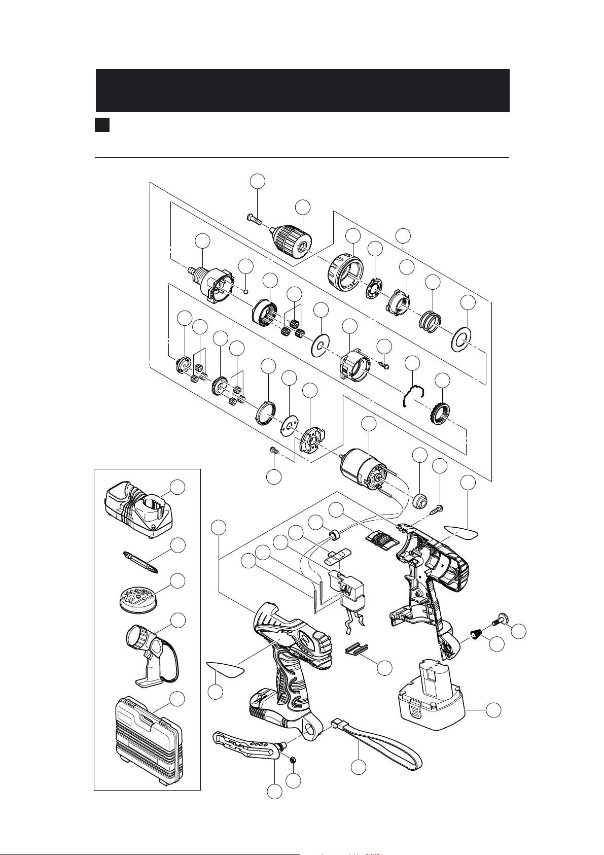
Hitachi Power Tools
ELECTRIC TOOL PARTS LIST
LIST NO. G823
CORDLESS DRIVER DRILL
Model DS 18DVF3
1
2
4
14
18
9
10
11
12
13
19
20
21
22
23
24
2005 • 4 •10
(E1)
3
5
6
7
8
15
16
17
501
502
503
504
505
29
36
30
31
28
32
25
26
27
35
34
33
42
41
40
43
37
39
38
Page 31

PARTS
ITEM
NO.
CODE NO.
DESCRIPTION REMARKS
1311-959 SPECIAL SCREW (LEFT HAND) M6X23 1
2 324-205
DRILL CHUCK 13VLRM-N (W/O CHUCK WRENCH)
3 324-490 GEAR BOX ASS’Y 1 INCLUD. 4-24
4 324-114 CLUTCH DIAL 1
5 324-108 CLICK SPRING 1
6 324-109 NUT 1
7 324-110 SPRING 1
8 324-347 WASHER (D) 1
9 324-491 FRONT CASE 1
10 306-936 STEEL BALL D5 6
11 324-111 RING GEAR 1
12 324-348 PLANET GEAR (C) SET (3 PCS.) 3
13 324-349 WASHER (A) 1
14 324-501 REAR CASE 1
15 324-357 SCREW SET D3X12 (4 PCS.) 4
16 324-115 SHIFT ARM 1
17 324-351 SLIDE RING GEAR 1
18 324-112 PINION (C) 1
19 324-352 PLANET GEAR (B) SET (3 PCS.) 3
20 324-492 PINION (B) 1
21 324-494 PLANET GEAR (A) SET (3 PCS.) 3
22 324-493 FIRST RING GEAR 1
23 324-355 WASHER (B) 1
24 324-495 MOTOR SPACER 1
25 324-497 MOTOR 1
26 313-687
TAPPING SCREW (W/FLANGE) D3X16 (BLACK) 8
27 NAME PLATE 1
28 317-333 MACHINE SCREW (W/SP. WASHER) M4X6 2
29 324-496 HOUSING (A).(B) SET 1
30 319-759 INTERNAL WIRE (BLACK) 100L 1
31 324-499 INTERNAL WIRE (RED) 140L 1
32 324-498 DC-SPEED CONTROL SWITCH 1
33 324-117 PUSHING BUTTON 1
*34 323-229 FERRITE CORE 1 FOR EUROPE
35 324-116 SHIFT KNOB 1
36 HITACHI LABEL 1
37 320-287 HOOK ASS’Y 1 INCLUD. 38
38 320-288 V-LOCK NUT M5 1
39 306-952 STRAP (BLACK) 1
40 315-141 TERMINAL SUPPORT (A) 1
41 319-926 HOOK SPRING 1
42 320-881 SPECIAL SCREW (A) M5 1
*43 322-882 BATTERY EB 1814SL (W/ENGLISH N.P.) 2
*43 324-365 BATTERY EB 1814SL (W/ENGLISH N.P.) 2 FOR USA, CAN
NO.
USED
1
DS 18DVF3
ALTERNATIVE PARTS--- 2 ---
*
4 -- 05
Page 32

STANDARD ACCESSORIES
ITEM
NO.
CODE NO.
DESCRIPTION REMARKS
501 CHARGER (MODEL UC 18YG) 1
502 983-006 + DRIVER BIT NO. 2 65L 1
503 BIT SET 1
504 TORCHLIGHT (MODEL UB 18D) 1
505 324-512 CASE 1
NO.
USED
OPTIONAL ACCESSORIES
ITEM
NO.
CODE NO.
DESCRIPTION
* 601 322-881 BATTERY EB 1820L (W/ENGLISH N.P.) 1 FOR USA, CAN
NO.
USED
DS 18DVF3
REMARKS
ALTERNATIVE PARTS --- 3 ---4 -- 05
*
Page 33

ITEM
NO.
CODE NO.
DESCRIPTION REMARKS
NO.
USED
DS 18DVF3
--- 4 ---
Printed in Japan
(050410N)
4 -- 05
Page 34
Hitachi Power Tools
ELECTRIC TOOL PARTS LIST
LIST NO. G822
CORDLESS DRIVER DRILL
Model DS 14DVF3
1
2
9
10
11
12
13
18
19
20
21
22
23
24
4
14
2005 • 4 •10
(E1)
3
5
6
7
8
15
16
17
501
502
503
504
505
37
30
31
32
29
25
26
27
28
36
35
34
33
43
42
41
44
38
40
39
Page 35

PARTS
ITEM
NO.
CODE NO.
DESCRIPTION REMARKS
1 324-503 SPECIAL SCREW (LEFT HAND) (B) M6X23 1
2 322-167
DRILL CHUCK 10VLRF-N (W/O CHUCK WRENCH)
3 324-490 GEAR BOX ASS’Y 1 INCLUD. 4-24
4 324-114 CLUTCH DIAL 1
5 324-108 CLICK SPRING 1
6 324-109 NUT 1
7 324-110 SPRING 1
8 324-347 WASHER (D) 1
9 324-491 FRONT CASE 1
10 306-936 STEEL BALL D5 6
11 324-111 RING GEAR 1
12 324-348 PLANET GEAR (C) SET (3 PCS.) 3
13 324-349 WASHER (A) 1
14 324-501 REAR CASE 1
15 324-357 SCREW SET D3X12 (4 PCS.) 4
16 324-115 SHIFT ARM 1
17 324-351 SLIDE RING GEAR 1
18 324-112 PINION (C) 1
19 324-352 PLANET GEAR (B) SET (3 PCS.) 3
20 324-492 PINION (B) 1
21 324-494 PLANET GEAR (A) SET (3 PCS.) 3
22 324-493 FIRST RING GEAR 1
23 324-355 WASHER (B) 1
24 324-495 MOTOR SPACER 1
25 324-483 MOTOR 1
26 324-485 SPACER 1
27 313-687
TAPPING SCREW (W/FLANGE) D3X16 (BLACK) 8
28 NAME PLATE 1
29 317-333 MACHINE SCREW (W/SP. WASHER) M4X6 2
30 324-482 HOUSING (A).(B) SET 1
31 324-484 INTERNAL WIRE (BLACK) 90L 1
32 324-499 INTERNAL WIRE (RED) 140L 1
33 324-498 DC-SPEED CONTROL SWITCH 1
34 324-117 PUSHING BUTTON 1
*35 323-229 FERRITE CORE 1 FOR EUROPE
36 324-116 SHIFT KNOB 1
37 HITACHI LABEL 1
38 320-287 HOOK ASS’Y 1 INCLUD. 39
39 320-288 V-LOCK NUT M5 1
40 306-952 STRAP (BLACK) 1
41 315-141 TERMINAL SUPPORT (A) 1
42 319-926 HOOK SPRING 1
43 320-881 SPECIAL SCREW (A) M5 1
*44 322-633 BATTERY EB 1414S (W/ENGLISH N.P.) 2
*44 324-367 BATTERY EB 1414S (W/ENGLISH N.P.) 2 FOR USA, CAN
NO.
USED
1
DS 14DVF3
ALTERNATIVE PARTS--- 2 ---
*
4 -- 05
Page 36

STANDARD ACCESSORIES
ITEM
NO.
CODE NO.
DESCRIPTION
501 CHARGER (MODEL UC 18YG) 1
502 983-006 + DRIVER BIT NO. 2 65L 1
503 BIT SET 1
* 504 TORCHLIGHT (MODEL UB 18D) 1 EXCEPT FOR GBR
505 324-502 CASE (BLACK) 1
NO.
USED
REMARKS
DS 14DVF3
4 -- 05
ALTERNATIVE PARTS --- 3 ---
*
Page 37

ITEM
NO.
CODE NO.
DESCRIPTION REMARKS
NO.
USED
DS 14DVF3
--- 4 ---
Printed in Japan
(050410N)
4 -- 05
Page 38

 Loading...