

Page 1
Page 2

Page 3
9
10
11
13
15
12
14
71
2 3 16
Page 4

1
防尘罩
2
插入至槽
3
前盖
4
工具柄
5
钻具夹持器
6
停止器
7
侧柄
8
K锥柄附加器
9
A锥度套管
0
钻头(带锥柄)
A
指示槽显示安装用于钻孔的描栓外径的标准深度。
B
K锥柄附加器
C
制销
D
台座
E
取心钻具
F
取心钻柄
G
导板
H
中间销
I
取心钻具尖端
J
取心钻具
K
取心钻具
L
取心钻柄
M
曲柄盖
N
侧柄
O
棒型柄
P
D型柄
Q
磨损极限
R
碳刷号
Dust cover
Insert up to the groove
Front cover
Tool shank
Tool holer
Stopper
Side handle
K–Taper shank adapter
A-taper sleeve
Drill bit (taper shank)
Indicating groove shows standard depth matching
the outside diameter of the anchor for drilling.
K–Taper shank adapter
Cotter
Support
Core bit
Core bit shank
Guide plate
Center pin
Core bit tip
Core bit
Core bit
Core bit shank
Crank cover
Side handle
Bar type handle
D type handle
Wear limit
No. of Carbon Brush
Page 5

一般安全规则
警告!
阅读说明
没有按照以下列举的说明而使用或操作将导致触电、
著火和/或严重伤害。
在所有以下列举的警告中术语“电动工具”指市电驱
动(有线)电动工具或电池驱动(无线)电动工具。
保存这些说明
1) 工作场地
a) 保持工作场地清洁和明亮。
混乱和黑暗的场地会引发事故。
b) 不要在易爆环境,如有易燃液体、气体或粉尘
的环境下操作电动工具。
电动工具产生的火花会点燃粉尘或气体。
c) 让儿童和旁观者离开后操纵电动工具。
分心会使你放松控制。
2) 电气安全
a) 电动工具插头必须与插座相配。
绝不能以任何方式改装插头。
需接地的电动工具不能使用任何转换插头。
未经改装的插头和相配的插座将减少触电危
险。
b) 避免人体接触接地表面,如管道、散热片和冰
箱。
如果你身体接地会增加触电危险。
c) 不得将电动工具暴露在雨中或潮湿环境中。
水进入电动工具将增加触电危险。
d) 不得滥用电线。
绝不能用电线搬运、拉动电动工具或拔出其插
头。
让电动工具远离热、油、锐边或运动部件。
受损或缠绕的电线会增加触电危险。
e) 当在户外使用电动工具时,使用适合户外使用
的外接电线。
适合户外使用的电线将减少触电危险。
3) 人身安全
a) 保持警觉,当操作电动工具时关注所从事的操
作并保持清醒。
切勿在有疲倦,药物、酒精或治疗反应下操作
电动工具。
在操作电动工具期间精力分散会导致严重人身
伤害。
b) 使用安全装置。始终配戴护目镜。
安全装置,诸如适当条件下的防尘面具、防滑
安全鞋、安全帽、听力防护等装置能减少人身
伤害。
c) 避免突然起动。
确保开关在插入插头时处于关断位置。
手指放在已接通电源的开关上或开关处于接通
时插入插头可能会导致危险。
d) 在电动工具接通之前,拿掉所有调节钥匙或扳
手。
遗留在电动工具旋转零件上的扳手或钥匙会导
致人身伤害。
e) 手不要伸得太长。
时刻注意脚下和身体平衡。
这样在意外情况下能很好地控制电动工具。
f) 著装适当。
不要穿宽松衣服或佩带饰品。
让你的头发、衣服和袖子远离运动部件。
宽松衣服、佩饰或长发可能会卷入运动部件。
g) 如果提供了与排屑装置、集尘设备连接用的装
置,则确保他们连接完好且使用得当。
使用这些装置可减少碎屑引起的危险。
4) 电动工具使用和主意事项
a) 不要滥用电动工具,根据用途使用适当的电动
工具。
选用适当的设计额定值的电动工具会使你工作
更有效、更安全。
b) 如果开关不能接通或关断工具电源,则不能使
用该电动工具。
不能用开关来控制的电动工具是危险的且必须
进行修理。
c) 在进行任何调节、更换附件或贮存电动工具之
前,必须从电源上拔掉插头和/或将电池盒脱
开电源。
这种防护性措施将减少电动工具突然起动的危
险。
d) 将闲置电动工具贮存在儿童所及范围之外,并
且不要让不熟悉电动工具或对这些说明不了解
的人操作电动工具。
电动工具在未经训练的用户手中是危险的。
e) 保养电动工具。检查运动件的安装偏差或卡
住、零件破损情况和影响电动工具运行的其他
条件。
如有损坏,电动工具必须在使用前修理好。
许多事故由维护不良的电动工具引发。
f) 保持切削刀具锋利和清洁。
保养良好的有锋利切削刃的刀具不易卡住而且
容易控制。
g) 按照使用说明书以及打算使用的电动工具的特
殊类型要求的方式,考虑作业条件和进行的作
业来使用电动工具、附件和工具的刀头等。
将电动工具用作那些与要求不符的操作可能会
导致危险情况。
5) 维修
a) 将你的电动工具送交专业维修人员,必须使用
同样的备件进行更换。
这样将确保所维修的电动工具的安全性。
注意事项
不可让儿童和体弱人士靠近工作场所。
应将不使用的工具存放在儿童和体弱人士接触不到的
地方。
4
Page 6
使用锤钻时应注意事项
䡬 耳朵应塞上耳塞,加以保护。
䡬 作业之后的钻头仍处在高热状态下,切不可摸
触,以免灼伤。
䡬 对墙壁、天花板和地板进行钻孔或钻碎作业时,
应彻底查明里面是否敷设电缆或导管。
䡬 使用锤钻时,应牢牢握住工具的操作柄和侧柄。
否则,所产生的反作用力会将孔钻歪,甚至会造
成危险。
规 格
电压(按地区)* (110V,115V,120V,127V,220V,230V,240V)
输入功率* 1140W
能力
无负荷速度 300 转/分
满载锤击率 2450 次/分
重量(不带电源线和侧柄) 9.8kg
*当须改变地区时应检查产品上的铭牌
钻头∶50mm
取心钻具∶125mm
标 准 附 件
(1) 壳体 .................................................................. 1
I型: 侧柄 ........................................... 1
(2) 侧柄 II型: 棒型柄 ....................................... 1
D型柄 ........................................ 1
安装I型或II型侧柄。
(3) 停止器 (仅限I型侧柄) .................................. 1
(4) 防尘罩 .............................................................. 1
(5) 六角头棒形扳手 ............................................... 1
(6) 电动锤润滑油 A ............................................... 1
标准附件可能不预先通告而径予更改。
选购附件(分开销售)
䡬 穿孔钻
(1) 钻头(六角柄)
总长: 420,570 mm
外径: 16, 18, 20, 22, 25, 28, 30, 32, 35, 38,
40, 44, 50 mm
䡬 锚栓孔钻
(3)制销
(1)K锥柄附加器 (2) A号锥度套管
䡬 大径孔钻
(1)中间销(带导板)(2)取心钻具 (3)取心钻柄
(1) 中间销
䢇 适用于 50 mm 至 125 mm 的取心钻具
(2) 取心钻具
䢇 外径 50, 65, 80, 90, 100, 125 mm
(3) 取心钻柄
䡬 破碎
(1)尖凿
总长∶300, 380, 450 mm
5
Page 7

䡬 开槽和饰边
(1)冷钻
总长∶300, 380, 450 mm
䡬 切柏油
(1) 刀具
宽度:50,75mm
总长度:400mm
䡬 喷射器(用于清除切层)
䡬 电动锤润滑油 A
500g(在油罐内)
30g(在管内)
选购附件可能不预先通告而径予更改。
用 途
䡬 混凝土钻孔
䡬 钻开锚栓孔
䡬 混凝土破碎,凿平,挖掘,切屑(与选购件配合
使用)
作 业 之 前
1. 电源
确认所使用的电源与工具铭牌上标示的规格是否
相符。
2. 电源开关
确认电源开关是否切断。若电源开关接通,则插
头插入电源插座时电动工具将出其不意地立刻转
动,从而招致严重事故。
3. 延伸电缆
若作业场所移到离开电源的地点,应使用负载量
足够、铠装合适的延伸线缆,并且要尽可能地短
些。
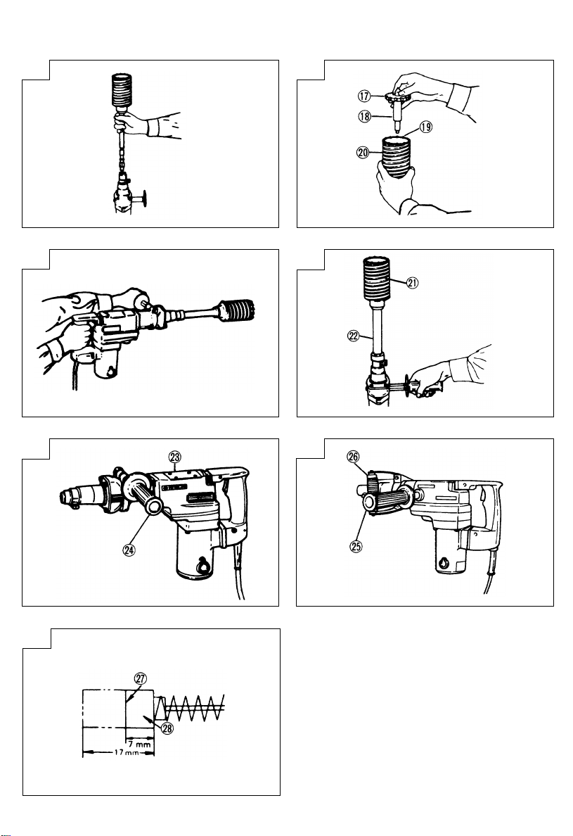
4. 如何安装防尘罩(图1)
请务必将防尘罩安装到钻头或锥柄附加器上。
将防尘罩插入直至卡到槽中。
注∶
如果钻头较粗,请从锤钻后端插入防尘罩。
5. 如何安装工具
注∶
对于诸如尖钻头和冷凿之类的工具,请只使用日立
牌原装产品。
(1) 擦净工具柄,并将橙色管中附带的润滑油涂于其
上。
(2) 沿箭头A的方向滑入夹持器,然后旋转180˚。
将工具柄的槽口转向下方,然后将其全部插入前
盖六角孔内。(图2)
(3) 转动夹持器,对齐前盖标记和夹持器标记,卡紧
工具。
注∶
按相反的次序拆除。
使用手提电动锤钻的方法
1. 钻孔方法(图 3)
(1) 使用侧柄或棒型柄
钻孔作业时请勿使用D型柄,D型柄不足以紧握机
身。
(2) 把钻头放到钻孔位置,然后拉动开关触发器。
(3) 锤钻只需稍按压,让切屑能顺利排出即可,无需
用力推压。
注意∶
本机内装有滑动离合器,钻头碰到钢筋等硬物时,
钻头会突然停止转动。这时,机身会因反冲力而转
动。因此,进行作业时,必须牢牢握住棒型柄和主
柄。
2. 如何切削或破碎(图 4)
(1) 使用侧柄或D型柄。
(2) 将尖凿放到切削或破碎的位置,利用锤钻自身的
重量操作锤钻。无须用力下压或推进。
6
Page 8

3. 如何使用停止器(图 5)
安装停止器
(1) 松开侧柄,将停止器的直立部分从前盖插入侧柄
的螺栓孔中。
(2) 松开侧柄,将停止器移到指定位置,然后顺时针
转动侧柄,固定停止器。
4. 使用K锥柄附加器时(图 6)
(1) 把钻头连同锥柄一起安装于锥柄附加器。
(2) 接通开关,钻开基孔,直到到达钻头上标示槽的
孔深为止。
(3) 用喷射器清除屑尘后,把塞子装配于锚栓尖端,
用手锤打入锚栓。
(4) 要卸下钻头(带锥柄)时,请将制销插入K锥柄附
加器槽,在锤钻下放置支撑物,然后用手锤锤击
制销。(图 7)
操作取心钻具的方法
使用取心钻具,可以钻开大口径孔和盲孔。这时候,
应使用取心钻具用选购附件(如中间销和取心钻
柄)。以便顺利开展作业。
1. 安装
注意∶
安装取心钻具之前,应从电源插座拆除电线插头。
(1) 把取心钻具安装于取心钻柄。(图 8)
在此之前,应注油到取心钻柄的螺纹部,使拆卸
时更为容易。
(2) 把取心钻柄安装于手提电动锤钻主体。其方法与
装配钻头和尖钻头时一样。(图 9)
(3) 把中间销插入导板,直到尽头为止。
(4) 将导板的凹陷部配套于取心钻具尖端。导板左、
右转动而使凹陷部位置移动。这时候,即使钻具
朝下导板也不会滑脱。(图 10)
2. 钻孔
(1) 把插头插入电源插座。
(2) 中间销里装有弹簧。垂直而平稳地把它压附于墙
壁和地板面上,使取心钻具尖端全面地接触,然
后开始钻孔作业。(图 11)
(3) 当孔深到达约 5mm 时,孔位就固定下来。此时,
可从取心钻具拆下中间销和导板,然后继续进行
作业。
注意∶
拆除中间销和导板时,必须先从电源插座拆卸插
头。
3. 拆卸取心钻具(图 12)
(1) 从上方握住锤钻(已经插入取心钻具),推动锤
钻进行重复撞击操作2至3次,使螺钉松开,锤钻
就易于拆解。
(2) 从锤钻下取心钻具,用一手握住取心钻具,以手
锤强力敲打取心钻柄的六角形大柄头部份 2 至 3
次,使圆头螺钉松开,锤钻就易于拆解。
更 换 润 滑 油
该机具有全气密结构以防尘和润滑油漏失。因此该机
可以长期不注油运转。更换润滑油方法如下∶
1. 润滑油更换周期
在购入后每用了六个月应更换润滑油。请到最近
的指定的日立代理店更换润滑油。
2. 润滑油的更换方法
注意∶
更换润滑油前应先关上电源并拔下电源插销。
(1) 取下曲轴罩并除净里面的润滑油。(图 13)
(2) 向曲轴壳内注入 20 克日立电锤润滑油 A(标准附
件,贮存在软管中)。
管中有30g润滑油,因此请涂抹满管的2/3。
(3) 更换润滑油后,正确地装上曲轴罩。
注∶
日立电锤润滑油 A 是一种低黏度型润滑油。如有
必要,请从经授权的日立维修服务代理店购买。
维 护 和 检 查
1. 工具检修
当使用变钝的工具时会降低效率并可能使电动机
出现故障,因此刚一发现就立即磨快或更换该工
具。
2. 检查安装螺钉
要经常检查安装螺钉是否紧固妥善。若发现螺钉
松了,应立即重新扭紧,否则会导致严重的事
故。
7
Page 9

3. 电动机的维护
电动机绕线是电动工具的心脏部。应仔细检查有
无损伤,是否被油液或水沾湿。
4. 检查碳刷(图 15)
电动机里的碳刷是一种消耗品。碳刷一旦使用到
磨损极限,电动机就会出现各种障碍;如果所使
用的碳刷是“自停式”,电动机将自动地停止转
动。遇到上述情况,应立即换上与图上代号一致
的新碳刷。此外,碳刷应经常保持干净状态,以
保证能在刷握里自由滑动。
5. 更换碳刷
松开固定螺丝并拆下罩盖。取下碳刷罩和碳刷。
更换碳刷后,请记住拧紧碳刷罩并装上罩盖。
6. 维修零部件一览表
注意∶
日立牌电动工具的维修、改造和检查须由经日立公
司授权的维修中心进行。
当要求维修或其他保养服务时,若将此零部件一览
表与电动工具一起呈交给经日立公司授权的维修中
心,将有助于维修或保养工作。
在操作和维修电动工具时,必须遵守贵国制定的安
全的有关规则和标准。
改造∶
日立牌电动工具经常加以改善和改造以采用最新的
先进技术。
因此,某些零部件可能变更,恕不另行通知。
注∶
为求改进,本手册所载规格可能不预先通告而径予
更改。
8
Page 10

English
GENERAL SAFETY RULES
WARNING!
Read all instructions
Failure to follow all instructions listed below may result in
electric shock, fire and/or serious injury.
The term “power tool” in all of the warnings listed below
refers to your mains operated (corded) power tool or
battery operated (cordless) power tool.
SAVE THESE INSTRUCTIONS
1) Work area
a) Keep work area clean and well lit.
Cluttered and dark areas invite accidents.
b) Do not operate power tools in explosive
atmospheres, such as in the presence of flammable
liquids, gases or dust.
Power tools create sparks which may ignite the
dust of fumes.
c) Keep children and bystanders away while operating
a power tool.
Distractions can cause you to lose control.
2) Electrical safety
a) Power tool plugs must match the outlet.
Never modify the plug in any way.
Do not use any adapter plugs with earthed (grounded)
power tools.
Unmodified plugs and matching outlets will reduce
risk of electric shock.
b) Avoid body contact with earthed or grounded
surfaces such as pipes, radiators, ranges and
refrigerators.
There is an increased risk of electric shock if your
body is earthed or grounded.
c) Do not expose power tools to rain or wet conditions.
Water entering a power tool will increase the risk
of electric shock.
d) Do not abuse the cord. Never use the cord for
carrying, pulling or unplugging the power tool.
Keep cord away from heat, oil, sharp edges or
moving parts.
Damaged or entangled cords increase the risk of
electric shock.
e) When operating a power tool outdoors, use an
extension cord suitable for outdoor use.
Use of a cord suitable for outdoor use reduces
the risk of electric shock.
3) Personal safety
a) Stay alert, watch what you are doing and use
common sense when operating a power tool.
Do not use a power tool while you are tired or under
the influence of drugs, alcohol or medication.
A moment of inattention while operating power
tools may result in serious personal injury.
b) Use safety equipment. Always wear eye protection.
Safety equipment such as dust mask, non-skid
safety shoes, hard hat, or hearing protection used
for appropriate conditions will reduce personal
injuries.
c) Avoid accidental starting. Ensure the switch is in the
off position before plugging in.
Carrying power tools with your finger on the
switch or plugging in power tools that have the
switch on invites accidents.
d) Remove any adjusting key or wrench before turning
the power tool on.
A wrench or a key left attached to a rotating part
of the power tool may result in personal injury.
e) Do not overreach. Keep proper footing and balance
at all times.
This enables better control of the power tool in
unexpected situations.
f) Dress properly. Do not wear loose clothing or
jewellery. Keep your hair, clothing and gloves away
from moving parts.
Loose clothes, jewellery or long hair can be caught
in moving parts.
g) If devices are provided for the connection of dust
extraction and collection facilities, ensure these are
connected and properly used.
Use of these devices can reduce dust related hazards.
4) Power tool use and care
a) Do not force the power tool. Use the correct power
tool for your application.
The correct power tool will do the job better and
safer at the rate for which it was designed.
b) Do not use the power tool if the switch does not turn
it on and off.
Any power tool that cannot be controlled with the
switch is dangerous and must be repaired.
c) Disconnect the plug from the power source before
making any adjustments, changing accessories, or
storing power tools.
Such preventive safety measures reduce the risk
of starting the power tool accidentally.
d) Store idle power tools out of the reach of children
and do not allow persons unfamiliar with the power
tool or these instructions to operate the power tool.
Power tools are dangerous in the hands of
untrained users.
e) Maintain power tools. Check for misalignment or
binding of moving parts, breakage of parts and any
other condition that may affect the power tools
operation.
If damaged, have the power tool repaired before use.
Many accidents are caused by poorly maintained
power tools.
f) Keep cutting tools sharp and clean.
Properly maintained cutting tools with sharp cutting
edges are less likely to bind and are easier to
control.
g) Use the power tool, accessories and tool bits etc., in
accordance with these instructions and in the manner
intended for the particular type of power tool, taking
into account the working conditions and the work to
be performed.
Use of the power tool for operations different from
intended could result in a hazardous situation.
5) Service
a) Have your power tool serviced by a qualified repair
person using only identical replacement parts.
This will ensure that the safety of the power tool
is maintained.
PRECAUTION
Keep children and infirm persons away.
When not in use, tools should be stored out of reach of
children and infirm persons.
9
Page 11

English
PRECAUTIONS ON USING HAMMER DRILL
䡬 Wear earplugs to protect your ears during operation.
䡬 Do not touch the bit during or immediately after
operation. The bit becomes very hot during operation
and could cause serious burns.
䡬 Before starting to break, chip or drill into a wall,
floor or ceiling, thoroughly confirm that such items
as electric cables or conduits are not buried inside.
䡬 Always hold the body handle and side handle of
the power tool firmly. Otherwise the counterforce
produced may result in inaccurate and even
dangerous operation.
SPECIFICATIONS
Voltage (by areas)* (110V, 115V, 120V, 127V, 220V, 230V, 240V)
Input* 1140W
Capacity Drill bit: 50 mm
No load speed 300/min.
Full-load impact rate 2450/min.
Weight (without cord, side handle) 9.8 kg
* Be sure to check the nameplate on product as it is subject to change by areas.
STANDARD ACCESSORIES
(1) Case ........................................................................... 1
(2) Side handle II type: Bar type handle ............... 1
Either type I or type II Side handle is attached.
(3) Stopper (I type Side handle only) ....................... 1
(4) Dust cover ................................................................. 1
(5) Hexagon bar wrench ............................................... 1
(6) Hammer grease A ................................................... 1
Standard accessories are subject to change without notice.
I type: Side handle ...................... 1
D type handle .................. 1
OPTIONAL ACCESSORIES (sold separately)
䡬 Through-hole drilling:
(1) Drill bit (hexagon shank)
Total length: 420, 570 mm
External dia.: 16, 18, 20, 22, 25, 28, 30, 32, 35, 38,
䡬 Anchor hole drilling:
40, 44, 50 mm
䡬 Large-dia. hole boring:
(1) Center Pin (Guide (2) Core (3) Core bit
(1) Center pin
Applied to core bits from 50 mm to 125 mm.
(2) Core bit
External dia.: 50, 65, 80, 90, 100, 125 mm
(3) Core bit shank
䡬 Crushing:
䡬 Groove digging and edging:
䡬 Asphalt cutting:
Core bit: 125 mm
plate) bit shank
(1) Cold chisel
Total length: 300, 380, 450 mm
(1) Cold chisel
Total length: 300, 380, 450 mm
(3) Cotter
(1) K-Taper shank adapter (2) A-Taper
sleeve
(1) Cutter
Width: 50, 75 mm
Total length: 400 mm
䡬 Syringe (for chip removal):
䡬 Hammer grease A:
500 g (in a can)
30 g (in a green tube)
Optional accessories are subject to change without notice.
10
Page 12

English
APPLICATIONS
䡬 Drilling holes in concrete
䡬 Drilling anchor holes
䡬 Crushing concrete, chipping, digging, and squaring
(by applying optional accessories)
PRIOR TO OPERATION
1. Power source
Ensure that the power source to be utilized conforms
to the power requirements specified on the product
nameplate.
2. Power switch
Ensure that the power switch is in the OFF position.
If the plug is connected to a receptacle while the
power switch is in the ON position, the power tool
will start operating immediately, which could cause
a serious accident.
3. Extension cord
When the work area is removed from the power
source, use an extension cord of sufficient thickness
and rated capacity. The extension cord should be
kept as short as practicable.
4. How to install dust cover (Fig. 1)
Always install the dust cover in the drill bit or the
taper shank adapter.
Insert the dust cover until it lies flush in the groove.
NOTE
For a thick drill bit, insert the dust cover from drill
rear.
5. How to install tool
NOTE
For tools such as a bull point and a cold chisel,
use only HITACHI genuine parts.
(1) Clean, the smear the tool shank with the grease
provided in the orange tube.
(2) Slide the tool holder in the direction of arrow A
and rotate it 180˚.
Turn the notch of the tool shank downward and
insert it fully into the hexagonal hole of the front
cover. (Fig. 2)
(3) Turn the tool holder and align the front cover mark
with the tool holder mark to secure.
NOTE
Remove in the reverse order of installation.
HOW TO USE THE HAMMER DRILL
1. How to drill holes (Fig. 3)
(1) Use the side handle or the Bar type handle.
Do not use D type handle during drilling operation,
since it may not be enough to hold the body firmly.
(2) Pull the switch trigger after applying the drill bit
tip to the drilling position.
(3) It is unnecessary to forcibly press the rotary hammer
main body. It is sufficient to slightly press the rotary
hammer to an extent that chips are freely discharged.
CAUTION
Although this machine is equipped with a safety
clutch, if the drill bit becomes bound in concrete
or other material, the resultant stoppage of the drill
bit could cause the machine body to turn in reaction.
Ensure that the main handle and the bar type handle
are gripped firmly during operation.
11
2. How to chip or crush (Fig. 4)
(1) Use the Side handle or the D type handle.
(2) By applying the Bull point tip to the chipping or
crushing position, operate the rotary hammer by
utilizing its own weight. Forcible pressing or thrusting
is unnecessary.
3. How to use stopper (Fig. 5)
Install the stopper
(1) Loosen the side handle and insert the straight portion
of the stopper into the handle bolt hole from the
front cover.
(2) Loosen the side handle, move the stopper to the
specified position and rotate the side handle
clockwise to fix the stopper.
4. When K-Taper shank adapter is used (Fig. 6)
(1) Install drill bit with taper shank in the K-Taper shank
adapter.
(2) Turn the power on and drill a base hole to the depth
sounded by the indicating groove on the drill bit.
(3) After cleaning out dust with the syringe, attach the
plug to the anchor tip and drive in the anchor with
a hand hammer.
(4) To remove the drill bit with taper shank, insert a
cotter into the slot of the K-Taper shank adapter,
place supports under the drill and tap the cotter
with a hand hammer. (Fig. 7)
HOW TO HANDLE A CORE BIT
When a core bit is used, large caliber holes and blind holes
can be drilled. In this case, use optional accerssories for
core bits (such as a center pin and core bit shank) for a
more rational operation.
1. Mounting
CAUTION
Prior to mounting a core bit, always disconnect the
plug from the receptacle.
(1) Mount the core bit on the core bit shank. (Fig. 8)
Before that, feed oil to the screw portion of core
bit shank for easily dismount.
(2) Mount the core bit shank on the Drill main body
in the same manner as in mounting the drill bit
and the bull point. (Fig. 9)
(3) Insert the center pin into the guide plate until it
reaches the extremity.
(4) Fit in the guide plate by aligning its concaved
portion with the core bit tip. When the position of
the concave is shifted by turning the guide plate
right or left, the guide plate never slips off even
when the Drill is used in a down ward direction.
(Fig. 10)
Page 13

English
2. Drilling holes
(1) Insert the plug into a receptacle.
(2) A spring is built in the center pin. By straightly and
gently pressing it to the wall or floor surface, the
entire surface of the core bit tip attains contact to
start the hole drilling job. (Fig. 11)
(3) When the hole depth reaches approximately 5 mm,
the hole position can be determined.
Then remove the center pin and guide plate from
the core bit and continue the hole drilling job.
CAUTION
When removing the center pin and guide plate,
always disconnect the plug from the power supply
receptacle.
3. How to dismount the core bit (Fig. 12)
(1) By holding the rotary hammer (with the core bit
inserted) in an upward position, drive the rotary
hammer to repeat impact operation two or three
times, whereby the screw is loosened and the rotary
hammer becomes ready for disassembly.
(2) Remove the core bit shank from the rotary hammer,
hold the core bit with one hand, and strongly strike
the head of the hexagonal portion of the core bit
shank with a hand hammer two or three times,
whereby the round head screw is loosened and the
rotary hammer is ready for disassembly.
HOW TO REPLACE GREASE
This machine is of full air-tight construction to protect
against dust and to prevent lubricant leakage.
Therefore, the machine can be used without lubrication
for long periods. Replace the grease as described below.
1. Grease replacement period
After purchase, replace grease after every 6 months
of usage. Ask for grease replacement at the nearest
authorized HITACHI Service Center.
2. Grease replacement
CAUTION
Before replacing the grease, turn the power off and
pull out the power plug.
(1) Remove the crank cover and wipe off the grease
inside. (Fig. 13)
(2) Apply 20 g of Hitachi Electric Hammer Grease A
(standard accessory, contained in tube) to the crank
case.
As the tube contain 30 g of grease, apply 2/3 of
the contained tube.
(3) After replacing the grease, install the crank case
securely.
NOTE
The Hitachi Electric Hammer Grease A is of the low
viscosity type. If necessary, purchase from an
authorized HITACH Service Center.
3. Maintenance of the motor
The motor unit winding is the very “heart” of the
power tool. Exercise due care to ensure the winding
does not become damaged and/or wet with oil or
water.
4. Inspecting the carbon brushes (Fig. 15)
The Motor employs carbon brushes which are
consumable parts. When they become worn to or
near the “wear limit”, it could result in motor trouble.
When an auto-stop carbon brush is equipped, the
motor will stop automatically. At that time, replace
both carbon brushes with new ones which have the
same carbon brush Numbers shown in the figure.
In addition, always keep carbon brushes clean and
ensure that they slide freely within the brush holders.
5. Replacement procedure
Loosen the set screw and remove the cap cover.
Remove the brush cap and carbon brush.
After replacing the carbon brush, do not forget to
tighten the brush cap securely and to install the cap
cover.
6. Service parts list
CAUTION
Repair, modification and inspection of Hitachi Power
Tools must be carried out by a Hitachi Authorized
Service Center.
This Parts List will be helpful if presented with the
tool to the Hitachi Authorized Service Center when
requesting repair or other maintenance.
In the operation and maintenance of power tools,
the safety regulations and standards prescribed in
each country must be observed.
MODIFICATIONS
Hitachi Power Tools are constantly being improved
and modified to incorporate the latest technological
advancements.
Accordingly, some parts may be changed without
prior notice.
NOTE
Due to HITACHI’s continuing program of research and
development, the specifications herein are subject to
change without prior notice.
MAINTENANCE AND INSPECTION
1. Inspecting the tool
Since use of a dull tool will degrade efficiency and
cause possible motor malfunction, sharpen or
replace the tool as soon as abrasion is noted.
2. Inspecting the mounting screws:
Regularly inspect all mounting screws and ensure
that they are properly tightened. Should any of the
screws be loose, retighten them immediately. Failure
to do so could result in serious hazard.
12
Page 14

13
Page 15

Item
No.
1A Stopper Rod
2 Handle Holder (A)
3 Handle Bolt
4 Striker
5 O-Ring (A)
6 Piston Pin
7 Piston
8 Cylinder Case
9 Seal Lock Hex. Socket Hd. Bolt M6 × 35
10 Bolt Washer M6
11 Roll Pin D6 × 25
12 O-Ring (D)
13 Needle Bearing (M526320)
14 Third Gear
15 Retaining Ring For D12 Shaft
16 Connecting Rod
17 Seal Lock Hex. Socket Hd. Bolt M4 × 12
18 Crank Cover
19 Seal Packing
20 O-Ring (S-55)
21 Crank Shaft
22 Retaining Ring For D47 Hole
23 O-RIng (B)
24 Ball Bearing (6204DDUCMPS2S)
25 Crank Case
26 Guide Plate
27 Handle Rubber
28 Hex. Socket Hd. Bolt M5 × 14
29 Holder Ass’y
30 Hex. Socket Hd. Bolt M8 × 20
31 Washer (C)
32 Shaft
33 Holder (A)
34 Holder (B)
35 Grip
36 Cylinder
37 Feather Key 3 × 3 × 20
38 Spring Case
39 Stopper Spring
40 Stopper Sleeve
41 Needle Roller
42 Caution Plate
43 Side Handle
44 Handle Holder (B)
45 Side Handle
46 Stop Lever
47 Seal Lock Hex. Socket Hd. Bolt M8 × 25
48 Front Cover
49 O-Ring (F)
50 O-Ring
51 Second Hammer
52 Damper Washer
53 Damper
54 Washer
55 HITACHI Level
56 Wind Guide (B)
57 Hex. Hd. Tapping Screw D5 × 70
58 Internal Wire
59 Stator Ass’y
60 Brush Terminal
61 Housing Ass’y
62 Hex. Socket Hd. Bolt (W/Flange) M6 × 60
63 Brush Holder
Part Name
Item
No.
64 Carbon Brush
65 Brush Cap
66 Cap Cover
67 Tapping Screw D4 × 10
68 Internal Wire Holder
69 Tapping Screw (W/Washer) D5 × 25
70 Pillar Terminal
71 Support (E)
72 Switch
73 Washer
74 Internal Wire
75 Name Plate
76 Rivet D2.5 × 4.8
77 Hex. Socket Set Screw M5 × 8
78 Tail Cover
79 Tapping Screw (W/Washer) D5 × 20
80 Distance Piece (B)
81 Tapping Screw (W/Washer) D4 × 25
82 Handle (B)
83 Handle Packing
84 Connector
85 Tapping Screw D4 × 16
86 Cord Clip
87 Handle (A)
88 Noise Suppressor
89 Connector
90 Cord Armor
91 Terminal
92 Cord
93 Seal Lock Hex. Socket Hd. Bolt M6 × 20
94 Woodruff Key 3 × 13
95 First Gear
96 Needle Bearing (M661)
97 Third Pinion
98 O-Ring (S-36)
99 Ball Bearing (6202DDUCMPS2S)
100 Second Gear
101 Steel Ball D6.35
102 Clutch Plate
103 Belleville Spring
104 Special Nut
105 Hex. Socket Set Screw M6
106 Bearing Washer (B)
107 Ball Bearing (629VVMC2EPS2L)
108 Bearing Washer (C)
109 Seal Packing
110 Gear Cover
111 Ball Bearing (6202VVCMPS2S)
112 Oil Seal (FPM807)
113 Sleeve
114 Fan
115 Armature Ass’y
116 Dust Washer
117 Ball Bearing (6200VVCMPS2S)
118 Handle Holder Ass’y
501A Case
502 Dust Cover
503 Hex. Bar Wrench 6 mm
504A Hammer Grease A (Contained tube, 30 g)
Part Name
14
Page 16

15
Page 17

Page 18

 Loading...