

Page 1
Drill
D13
Handling instructions
Read through carefully and understand these instructions before use.
Page 2
12
5
6
(L) (R)
3
17 m m
English
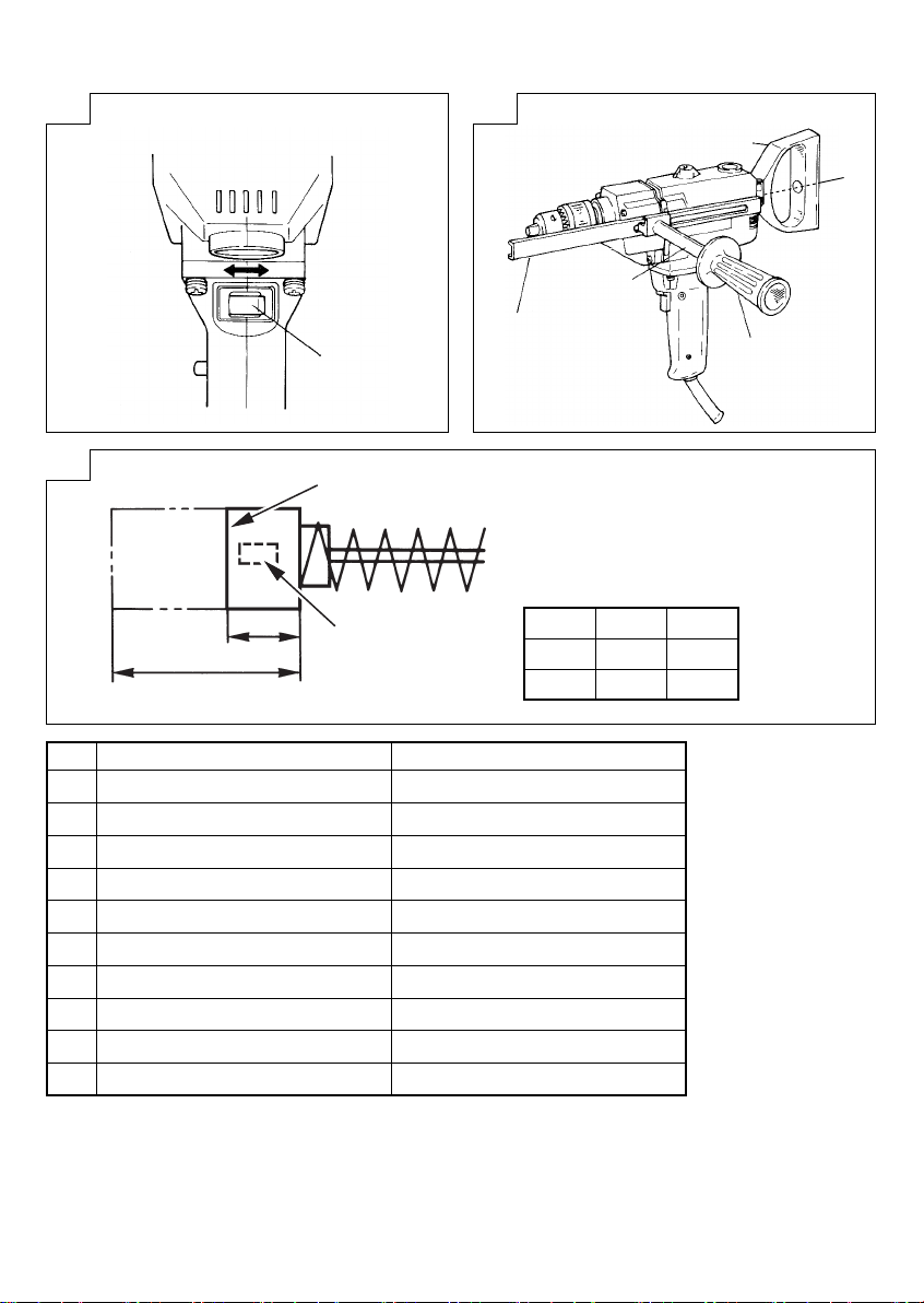
Lever
1
Depth stopper
2
Handle joint
3
Side handle
4
Spade handle
5
Bolt
6
Wear li mit
7
No. of carbon brush
8
Usual carbon brush
9
Auto-stop carbon brush
0
3
2
1
4
7
a
8
9
0
ﺔﻳﺑﺭﻌﻟﺍ
ﺔﻳﺩﺎﻌﻟﺍ ﻥﻭﺑﺭﻛﻟﺍ ﺓﺎﺷﺭﻓ
ﻑﻗﻭﺗﻟﺍ ﺔﻳﺋﺎﻘﻠﺗ ﻥﻭﺑﺭﻛﻟﺎﺑ ﻝﻘﺻ ﺓﺎﺷﺭﻓ
a
6 mm 43
7 mm 73
ﻉﺍﺭﺫ
ﻕﻣﻌﻟﺍ ﺩﺍﺩﺳ
ﺽﺑﻘﻣﻟﺍ ﺔﻠﺻﻭ
ﻲﺑﻧﺎﺟ ﺽﺑﻘﻣ
ﻑﺍﺭﺟﻣﻟﺍ ﺽﺑﻘﻣ
ﺭﺎﻣﺳﻣ
ﻝﻛﺂﺗﻟﺍ ﺩﺣ
ﺔﻳﻧﻭﺑﺭﻛﻟﺍ ﺵﺭﻔﻟﺍ ﺩﺩﻋ
8
2
Page 3

English
GENERAL POWER TOOL SAFET Y WARNINGS
WARNING
Read all safet y warnings and all instructions.
Failure to follow the warnings and instructions may result in
electric shock, fi re and/or serious injur y.
Save all wa rnings and ins tructions f or future ref erence.
The term “power tool” in the warnings refers to your
mains-operated (corded) power tool or battery-operated
(cordless) power tool.
1) Work ar e a s a fe t y
a) Keep work area clean and well lit.
Cluttered or dark areas invite accidents.
b) Do not operate power tools in explosive
atmospheres, such as in the presence of
fl ammable liquids, gases or dust.
Power tools create sparks which may ignite the dust
or fumes.
c) Keep children and bystanders away while
operating a power tool.
Distractions can cause you to lose control.
2) Electrical safety
a) Power tool plugs must match the outlet .
Never modify the plug in any way.
Do not use any adapter plugs with earthed
(grounded) power tools.
Unmodifi ed plugs and matching outlets will reduce
risk of electric shock.
b) Avoid body contact with earthed or grounded
surfaces, such as pipes, radiators, ranges and
refrigerators.
There is an increased risk of electric shock if your
body is earthed or grounded.
c) Do not expose power tools to rain or wet
conditions.
Water entering a power tool will increase the risk of
electric shock.
d) Do not abuse the cord. Never use the cord for
carrying, pulling or unplugging the power tool.
Keep cord away from heat, oil, sharp edges or
moving parts.
Damaged or entangled cords increase the risk of
electric shock.
e) When operating a power tool outdoors, use an
extension cord suitable for outdoor use.
Use of a cord suitable for outdoor use reduces the
risk of electric shock.
f) If operating a power tool in a damp location
is unavoidable, use a residual current device
(RCD) protected supply.
Use of an RCD reduces the risk of electric shock.
3) Personal safety
a) Stay alert, watch what you are doing and use
common sense when operating a power tool.
Do not use a power tool while you are tired
or under the infl uence of drugs, alcohol or
medication.
A moment of inattention while operating power tools
may result in serious personal injury.
b) Use personal protective equipment. Always
wear eye protection.
Protective equipment such as dust mask, non-skid
safety shoes, hard hat, or hearing protection used
for appropriate conditions will reduce personal
injuries.
c) Prevent unintentional star ting. Ensure the
switch is in the off -position before connecting
to power source and/or batter y pack , picking
up or carrying the tool.
Carr ying power tools with your fi nger on the switch
or energising power tools that have the switch on
invites accidents.
d) Remove any adjusting key or wrench before
turning the power tool on.
A wrench or a key left attached to a rotating part of
the power tool may result in personal injury.
e) Do not overreach. Keep proper footing and
balance at all times.
This enables better control of the power tool in
unexpected situations.
f) Dress properly. Do not wear loose clothing or
jewellery. Keep your hair, clothing and gloves
away from moving parts.
Loose clothes, jewellery or long hair can be caught
in moving parts.
g) If devices are provided for the connection of
dust extraction and collection facilities, ensure
these are connected and properly used.
Use of dust collection can reduce dust-related
hazards.
4) Power tool use and care
a) Do not force the power tool. Use the correct
power tool for your application.
The correct power tool will do the job better and
safer at the rate for which it was designed.
b) Do not use the power tool if the switch does not
turn it on and off .
Any power tool that cannot be controlled with the
switch is dangerous and must be repaired.
c) Disconnect the plug from the power source
and/or the bat tery pack from the power tool
before making any adjustments, changing
accessories, or storing power tools.
Such preventive safety measures reduce the risk of
starting the power tool accidentally.
d) Store idle power tools out of the reach of
children and do not allow persons unfamiliar
with the power tool or these instructions to
operate the power tool.
Power to ols are dangero us in the hands of untrained
users.
e) Maintain power tools. Check for misalignment
or binding of moving parts, breakage of parts
and any other condition that may aff ect the
power toolsʼ operation.
If damaged, have the power tool repaired
before use.
Many accidents are caused by poorly maintained
power tools.
f) Keep cut ting tools sharp and clean.
Properly maintained cutting tools with sharp cutting
edges are less likely to bind and are easier to
control.
g) Use the power tool, accessories and tool bits
etc. in accordance with these instructions,
taking into account the working conditions and
the work to be performed.
Use of the power tool for operations diff erent from
those i ntended coul d result in a haza rdous situati on.
3
Page 4

English
5) Service
a) Have your power tool serviced by a qualifi ed
repair person using only identical replacement
parts.
This will ensure that the safety of the power tool is
maintained.
PRECAUTION
Keep children and infi rm persons away.
When not in use, tools should be stored out of reach
of children and infi rm persons.
DRILL SAFETY WARNINGS
1. Use auxiliary handle(s), if supplied with the tool.
Loss of control can cause personal injury.
Hold power tool by insulated gripping sur faces,
2.
when performing an operation where the cutting
accessory m ay contact hidden wiring or its own cord.
Cutting accessory contacting a "live" wire may make
exposed metal parts of the power tool "live" and could
give the operator an electric shock.
3. Never wear gloves during operation.
Gloves are sometimes caught by rotating parts,
resulting in serious injury. Do not use gloves during
operation.
4. Install the side handle and hold the tool fi rmly with both
hands.
One-hand operation is very dangerous. Always install
the side handle and hold the tool with both hands.
Holding the tool insuffi ciently can result in serious
damage during operation.
5. Hold the main handle by your right hand.
Holding the main handle by your left hand may make
the switch be unintentionally locked.
SPECIFICATIONS
Voltage (by areas)* (110 V, 115 V, 120 V, 127 V, 220 V, 230 V, 240 V)
Power Input* 720 W
No-load speed* 650 /min
Capacity
Weight (without cord) 3 kg
* Be sure to check the nameplate on product as it is subject to change by areas.
STANDARD ACCESSORIES
(1) Chuck Wrench ..............................................................1
(2) Side handle ..................................................................1
Stand ard accessor ies are subje ct to change wit hout notice.
OPTIONAL ACCESSORIES (sold separately)
(1) Handle joint
(2) Depth Stopper
Optional accessories are subject to change without notice.
APPLICATIONS
Drilling in metal, lumber and plastics.
PRIOR TO OPERATION
1. Power source
Ensure that the power source to be utilized conforms
to the power requirements specifi ed on the product
nameplate.
2. Power switch
Ensure that the power switch is in the OFF position. If
the plug is connected to a receptacle while the power
switch is in the ON position, the power tool will star t
operating immediately, inviting serious accident.
3. Extension cord
When the work area is removed from the power source.
Use an extension cord of suffi cient thickness and rated
capaci ty. The extension cord sho uld be kept as shor t as
practicable.
Steel 13 mm
Wood 40 mm
4. Confi rm the direction of bit rotation
The drill bit rotates clock wise (when viewed from the
rear) when the lever of the reversing switch is set to the
“R” position, and rotates in the reverse direction when
the lever of the reversing switch is set to the “L” position.
5. Fitting the drill bit
Fit the drill bit into the chuck and use the chuck key
to secure it, tightening the chuck by each of the three
holes in turn.
6. Selecting the appropriate drill bit
○ When boring metal or plastic
Use ordinary metalworking drill bits.
Sizes range from a minimum of 1.2 mm to chuck
maximum capacity.
○ When boring wood
Use ordinary woodworking drill bits.
However, when drilling 6.5 mm or smaller holes, use a
metalworking drill bit.
7. Installing spade handle
The spade handle can be installed on the back of
the drill. Insert the bolt through the hole in the spade
handle, locate the spade handle in the desired position
and tighten the bolt fi rmly.
8. Installing the side handle
The side handle screws into the housing on either side
of the gear cover. For safe operation, use of the side
handle is necessary. Especially in heavy duty drilling,
use handle joint and side handle.
9. Installing the depth stopper (optional accessory)
The depth stopper which is useful for adjusting the
drilling depth is available. Install the depth stopper to
the gear cover using the side handle or set screw.
4
Page 5

English
10. RCD
Th e use of a residu al current dev ice with a rate d residual
current of 30mA or less at all times is recommended.
PRACTICAL HANDLING PROCEDURES
1. Pressure
Drilling will NOT be accelerated by placing heavy
pressure on the drill. Such action will only result in a
damaged drill bit, decreased drilling effi ciency, and/or
shortened service life of the drill.
2. Using a large diameter drill bit
The larger the drill bit diameter, the larger the reactive
force on your arm. Be careful not to lose control of the
drill because of this reactive force. To maintain fi rm
control, establish a good foothold, hold the drill tightly
with both hands, and ensure that the drill is vertical to
the material being drilled.
3. When drilling completely through the material
When the drill bit bores completely through the
material, careless handing often results in broken drill
bit or damage to the drill body itself due to the sudden
movement of the drill.
Always be alert and ready to release pushing force
when drilling through the material.
4. Switch operation
(1) Trigger switch
By pulling the trigger switch and depressing the
stopper, the switch is held in the ON position for
continuous drilling. To turn the drill OFF, pull the trigger
switch again and release.
(2) Reversing switch
This drill can rotate both clockwise (for drilling)
and counterclockwise (for releasing the drill bit) by
operating the reversing switch.
CAUTION
Never change the direc tion of rotation while th e motor is
rotating. Turn the power switch off before changing the
direction of rotation.
5. Precautions on boring
The drill bit may become overheated during operation;
however, it is suffi ciently operable. Do not cool the drill
bit in water or oil.
6. Caution concerning immediately after use
Immediately after use, while it is still revolving, if
the Drill is placed on a location where considerable
ground chips and dust have accumulated, dust may
occasionally be absorbed into the drill mechanism.
Always pay at tention to this undesirable possibility.
MAINTENANCE AND INSPECTION
1. Inspecting the drill bits
Since use of an abraded drill bits will cause motor
malfunctioning and degraded effi ciency, replace the
drill bits with a new one or resharpening without delay
when abrasion is noted.
2. Inspecting the mounting screws
Regularly inspect all mounting screws and ensure that
they are properly tightened. Should any of the screws
be loose, retighten them immediately. Failure to do so
could result in serious hazard.
3. Inspecting the carbon brushes
The motor employs carbon brushes which are
consumable parts.
When the brushes are worn down, motor trouble may
result . When the brush es are worn down to th e limit line,
replace the brushes with new ones. Keep the brushes
clean, so that they smoothly slide into the brush holders.
When replacing the brushes with new ones, be sure to
use a pair o f brushes for HiKOK I ELECTRIC DRILL Type
D13 corresponding to the illustrated number. Auto-stop
carbon brushes automatically cut off the electric circuit,
when it is worn down to the wear limit.
This indicates the replacement time of the brush and
prevents damage of the commutator.
4. Replacing carbon brushes
Disassemble the brush caps with a slotted-head
screwdriver. The carbon brushes can then be easily
removed.
5. Maintenance of the motor
The motor unit winding is the very “heart ” of the power
tool. Exercise due care to ensure the winding does not
become damaged and/or wet with oil or water.
6. Replacing supply cord
If the replacement of the supply cord is necessar y, it
has to be don e by H iKOKI Authorized Ser vice Center to
avoid a safet y hazard.
7. Service parts list
A: Item No.
B: Code No.
C: No. Used
D: Remarks
CAUTION
Repair, modifi cation and inspection of HiKOKI Power
Tools must be carried out by a HiKOKI Authorized
Service Center.
Thi s Par ts Li st will be hel pful if pr esen ted w ith t he to ol to
the HiKOKI Au thorized Ser vice Center when requ esting
repair or other maintenance.
In the operation and maintenance of power tools, the
safety regulations and standards prescribed in each
countr y must be observed.
MODIFICATION
HiKOKI Power Tools are constantly being improved
and modifi ed to incorporate the latest technological
advancements.
Accordingly, some parts (i.e. code numbers and/or
design) may be changed without prior notice.
NOTE
Due to HiKOKI’s continuing program of research and
development, the specifi cations herein are subject to
change without prior notice.
5
Page 6

ﺔﻴﺑﺮﻌﻟا
ﺔﻣﺩﺧﻟﺍ ءﺍﺯﺟﺃ ﺔﻣﺋﺎﻗ
ﺭﺻﻧﻌﻟﺍ ﻡﻗﺭ :A
ﺯﻣﺭﻟﺍ ﻡﻗﺭ :B
ﻡﺩﺧﺗﺳﻣﻟﺍ ﻡﻗﺭﻟﺍ :C
ﺕﺎﻣﻼﻌﻟﺍ :D
HiKOKI
ﺕﺍﻭﺩﻷ ﺹﺣﻔﻟﺍﻭ ،ﻝﻳﺩﻌﺗﻟﺍﻭ ،ﺡﻼﺻﻹﺍ ﻝﺎﻣﻋﺃ ﺫﻳﻔﻧﺗ ﺏﺟﻳ
HiKOKI
ﺔﻣﺩﺧ ﺯﻛﺭﻣﻟ ﺓﺍﺩﻷﺍ ﻊﻣ ﺎﻬﻣﻳﺩﻘﺗ ﺩﻧﻋ ﺓﺩﻳﻔﻣ ﻩﺫﻫ ءﺍﺯﺟﻷﺍ ﺔﻣﺋﺎﻗ
.ﺩﻣﺗﻌﻣﻟﺍ ﺔﻣﺩﺧﻟﺍ ﺯﻛﺭﻣ ﻝﺑﻗ ﻥﻣ
ﻪﻳﺑﻧﺗ
.ﺔﻧﺎﻳﺻﻟﺍ ﻝﺎﻣﻋﺃ ﻥﻣ ﺎﻫﺭﻳﻏ ﻭﺃ ﺡﻼﺻﻹﺍ ﺏﻠﻁ ﺩﻧﻋ ﺩﻣﺗﻌﻣ
ﺕﺎﻣﻳﻠﻌﺗ ﻉﺎﺑﺗﺍ ﺏﺟﻳ ،ﺎﻬﺗﻧﺎﻳﺻ ﻭﺃ ﺔﻳﺋﺎﺑﺭﻬﻛﻟﺍ ﺩﺩﻌﻟﺍ ﻝﻳﻐﺷﺗ ﺔﻟﺎﺣ ﻲﻓ
.ﺔﻟﻭﺩ ﻝﻛﺑ ﺔﺻﺎﺧﻟﺍ ﺭﻳﻳﺎﻌﻣﻟﺍﻭ ﻥﺎﻣﻷﺍ
ﺕﺎﻳﻧﻘﺗﻟﺍ ﺙﺩﺣﻷ ﺎًﻌﺑﺗ ﺎﻬﻠﻳﺩﻌﺗﻭ ﺭﺍﺭﻣﺗﺳﺎﺑ
HiKOKI
ﺕﺍﻭﺩﺃ ﻥﻳﺳﺣﺗ ﻡﺗﻳ
ﺕﻼﻳﺩﻌﺗﻟﺍ
.ﺔﻣﺩﻘﺗﻣﻟﺍ
(ﻡﻳﻣﺻﺗﻟﺍ ﻭﺃ/ﻭ ﺯﻭﻣﺭﻟﺍ ﻡﺎﻗﺭﺃ ﻝﺛﻣ) ءﺍﺯﺟﻷﺍ ﺽﻌﺑ ﺭﻳﻳﻐﺗ ﻡﺗﻳ ﺩﻗ ،ﻙﻟﺫﻟﻭ
.ﻕﺑﺳﻣ ﻡﻼﻋﺇ ﻥﻭﺩ
ﺕﺎﻔﺻﺍﻭﻣﻟﺍ ﺭﻳﻐﺗﺗ ،ﺭﻣﺗﺳﻣﻟﺍ ﺭﻳﻭﻁﺗﻟﺍﻭ ﺙﺣﺑﻠﻟ
HiKOKI
ﺔﻅﺣﻼﻣ
ﺞﻣﺎﻧﺭﺑﻟ ﺎًﻌﺑﺗ
.ﻕﺑﺳﻣ ﻡﻼﻋﺇ ﻥﻭﺩ ﺎﻧﻫ ﺓﺭﻭﻛﺫﻣﻟﺍ
7
.ﻙﻋﺍﺭﺫ ﻰﻠﻋ ﺔﻳﻠﻋﺎﻔﺗﻟﺍ ﺓﻭﻘﻟﺍ ﺕﺩﺍﺯ ﺎﻣﻠﻛ ،ﺭﻔﺣﻟﺍ ﺏﻘﺛﻣ ﺭﻁﻗ ﺩﺍﺯ ﺎﻣﻠﻛ
ﺭﻳﺑﻛ ﺭﻁﻗ ﻱﺫ ﺭﻔﺣ ﺏﻘﺛﻣ ﻡﺍﺩﺧﺗﺳﺍ 2
ﻅﺎﻔﺣﻠﻟ .ﺔﻳﻠﻋﺎﻔﺗﻟﺍ ﺓﻭﻘﻟﺍ ﺏﺑﺳﺑ ﺏﻘﺛﻣﻟﺍ ﻲﻓ ﻡﻛﺣﺗﻟﺍ ﺩﻘﻓ ﻡﺩﻋ ﻰﻠﻋ ﺹﺭﺣﺍ
ﻙﻳﺩﻳﺑ ﻡﺎﻛﺣﺈﺑ ﺏﻘﺛﻣﻟﺍ ﻙﺳﻣﺃﻭ ،ﻡﺩﻗ ﺊﻁﻭﻣ ﻊﺿ ،ﺕﺑﺎﺛﻟﺍ ﻡﻛﺣﺗﻟﺍ ﻰﻠﻋ
.ﺎﻬﻳﻓ ﺏﻘﺛﻟﺍ ﻡﺗﻳ ﻲﺗﻟﺍ ﺓﺩﺎﻣﻟﺍ ﻰﻠﻋ ﻱﺩﻭﻣﻋ ﻝﻛﺷﺑ ﻥﻳﺗﻧﺛﻻﺍ
ﺎًﺑﻟﺎﻏ ﻝﺎﻣﻫﺈﺑ ﻝﻣﺎﻌﺗﻟﺍ ﻱﺩﺅﻳ ﺩﻗ ،ﺓﺩﺎﻣﻟﺍ ﺭﺑﻋ ﺎًﻣﺎﻣﺗ ﺏﻘﺛﻣﻟﺍ ﻕﺭﺗﺧﻳ ﺎﻣﺩﻧﻋ
ﺓﺩﺎﻣﻟﺍ ﺭﺑﻋ ﻝﻣﺎﻛ ﻝﻛﺷﺑ ﺏﻘﺛﻟﺍ ﺩﻧﻋ
ﺔﺋﺟﺎﻔﻣﻟﺍ ﺔﻛﺭﺣﻟﺍ ﺏﺑﺳﺑ ﻪﺗﺍﺫ ﺏﻘﺛﻣﻟﺍ ﻝﻛﻳﻫ ﻑﻠﺗ ﻭﺃ ﺏﻘﺛﻣﻟﺍ ﺭﺳﻛ ﻰﻟﺇ
.ﺓﺩﺎﻣﻟﺍ ﻝﺧﺍﺩ ﺏﻘﺛﻟﺍ ﺩﻧﻋ ﻊﻓﺩﻟﺍ ﺓﻭﻗ ﺭﻳﺭﺣﺗﻟ ﺍًﺩﻌﺗﺳﻣﻭ ﺎﻣﺋﺍﺩ ﺎًﻬﺑﺗﻧﻣ ﻥﻛ
ﺡﺎﺗﻔﻣﻟﺍ ﻝﻳﻐﺷﺗ
ﺩﺎﻧﺯﻟﺍ ﺡﺎﺗﻔﻣ (1)
ﻙﺎﺳﻣﻹﺍ ﻡﺗﻳ ،ﻑﺎﻘﻳﻹﺍ ﺓﺍﺩﺃ ﻰﻠﻋ ﻁﻐﺿﻟﺍﻭ ﻝﻳﻐﺷﺗﻟﺍ ﺡﺎﺗﻔﻣ ﺏﺣﺳ ﺔﻁﺳﺍﻭﺑ
ﺏﺣﺳﺍ ،ﺏﻘﺛﻣﻟﺍ ﻝﻳﻐﺷﺗ ﻑﺎﻘﻳﻹ .ﺭﻣﺗﺳﻣﻟﺍ ﺏﻘﺛﻠﻟ ﻝﻳﻐﺷﺗﻟﺍ ﻊﺿﻭ ﻲﻓ
.ﻩﺭﺭﺣ ﻡﺛ ﻯﺭﺧﺃ ﺓﺭﻣ ﺡﺩﻘﻣﻟﺍ ﺡﺎﺗﻔﻣ
ﺱﻛﻌﻟﺍ ﺡﺎﺗﻔﻣ (2)
(ﺏﻘﺛﻠﻟ) ﺔﻋﺎﺳﻟﺍ ﺏﺭﺎﻘﻋ ﻩﺎﺟﺗﺍ ﻲﻓ ﺏﻘﺛﻣﻟﺍ ﺍﺫﻫ ﺭﻭﺩﻳ ﻥﺃ ﻥﻛﻣﻣﻟﺍ ﻥﻣ
ﺡﺎﺗﻔﻣ ﻝﻳﻐﺷﺗ ﺔﻁﺳﺍﻭﺑ (ﺭﻔﺣﻟﺍ ﺏﺎﻘﺛﻣ ﺭﻳﺭﺣﺗﻟ) ﺔﻋﺎﺳﻟﺍ ﺏﺭﺎﻘﻋ ﺱﻛﻋﻭ
.ﺱﻛﻌﻟﺍ
ﻝﻳﻐﺷﺗ ﻑﺎﻘﻳﺈﺑ ﻡﻗ .ﻙﺭﺣﻣﻟﺍ ﻥﺍﺭﻭﺩ ﺩﻧﻋ ﺭﻳﻭﺩﺗﻟﺍ ﻩﺎﺟﺗﺍ ﺭﻳﻳﻐﺗﺑ ﻡﻘﺗ ﻻ
.ﻥﺍﺭﻭﺩﻟﺍ ﻩﺎﺟﺗﺍ ﺭﻳﻳﻐﺗ ﻝﺑﻗ ﺔﻗﺎﻁﻟﺍ
ﻝﺑﺎﻗ ﻭﻬﻓ ﻙﻟﺫ ﻊﻣﻭ ،ﻝﻳﻐﺷﺗﻟﺍ ءﺎﻧﺛﺃ ﺭﻔﺣﻟﺍ ﺏﻘﺛﻣ ﺓﺭﺍﺭﺣ ﺩﺍﺩﺯﺗ ﺩﻗ
ﺭﻔﺣﻟﺍ ءﺎﻧﺛﺃ ﺕﺎﻁﺎﻳﺗﺣﻻﺍ
.ٍﻑﺎﻛ ﻝﻛﺷﺑ ﻝﻳﻐﺷﺗﻠﻟ
.ﺕﻳﺯﻟﺍ ﻭﺃ ءﺎﻣﻟﺎﺑ ﺭﻔﺣﻟﺍ ﺏﻘﺛﻣ ﺩﻳﺭﺑﺗﺑ ﻡﻘﺗ ﻻ
ﻥﺎﻛ ﺍﺫﺇ ،ﻥﺍﺭﻭﺩﻟﺍ ﻲﻓ ﻩﺭﺍﺭﻣﺗﺳﺍ ءﺎﻧﺛﺃﻭ ،ًﺓﺭﺷﺎﺑﻣ ﺏﻘﺛﻣﻟﺍ ﻡﺍﺩﺧﺗﺳﺍ ﺩﻌﺑ
ﺓﺭﺷﺎﺑﻣ ﻡﺍﺩﺧﺗﺳﻻﺍ ﺩﻌﺑ ﺎﻣﺑ ﻕﻠﻌﺗﻳ ﺎﻣﻳﻓ ﻪﻳﺑﻧﺗ
ﻡﺗﻳ ﺩﻘﻓ ،ﺭﺎﺑﻏﻭ ﺓﺭﻳﺑﻛ ﺔﻳﺿﺭﺃ ﺢﺋﺍﺭﺷ ﻪﻳﻓ ﻡﻛﺍﺭﺗﺗ ﻥﺎﻛﻣ ﻰﻠﻋ ﺎًﻋﻭﺿﻭﻣ
.ﺏﻘﺛﻣﻟﺍ ﺔﻟﺁ ﻝﺧﺍﺩ ﺭﺎﺑﻐﻟﺍ ﺹﺎﺻﺗﻣﺍ ﺎًﻧﺎﻳﺣﺃ
.ﺏﻭﻏﺭﻣﻟﺍ ﺭﻳﻏ ﻝﺎﻣﺗﺣﻻﺍ ﺍﺫﻬﻟ ﺎًﻣﺋﺍﺩ ﻪﺑﺗﻧﺍ
ﺹﺣﻔﻟﺍﻭ ﺔﻧﺎﻳﺻﻟﺍ
ﻝﻳﻠﻘﺗﻟﺍﻭ ﻙﺭﺣﻣﻟﺍ ﻑﻠﺗ ﻰﻟﺇ ﻱﺩﺅﺗ ﺔﻠﻛﺂﺗﻣﻟﺍ ﺭﻔﺣﻟﺍ ﺏﻗﺎﺛﻣ ﻥﺃ ﻰﻟﺇ ﺍًﺭﻅﻧ
ﻱﻷ ﻙﺗﻅﺣﻼﻣ ﺭﻭﻓ ﺎﻫﺫﺣﺷﺑ ﻡﻗ ﻭﺃ ﺭﻔﺣﻟﺍ ﺏﻗﺎﺛﻣ ﻝﺩﺑﺗﺳﺍ ،ﺓءﺎﻔﻛﻟﺍ ﻥﻣ
ﺎﻬﻁﺑﺭ ﻡﺎﻛﺣﺇ ﻥﻣ ﺩﻛﺄﺗﻟﺍﻭ ﺕﻳﺑﺛﺗﻟﺍ ﺭﻳﻣﺎﺳﻣ ﺔﻓﺎﻛﻟ ﻱﺭﻭﺩﻟﺍ ﺹﺣﻔﻟﺎﺑ ﻡﻗ
.ﺭﻭﻔﻟﺍ ﻰﻠﻋ ﺎﻬﻁﺑﺭ ﻡﺎﻛﺣﺈﺑ ﻡﻗ ،ﺭﻳﻣﺎﺳﻣ ﺔﻳﺃ ﻙﻓ ﺔﻟﺎﺣ ﻲﻓ .ﺢﻳﺣﺻ ﻝﻛﺷﺑ
.ﺭﻁﺎﺧﻣ ﻰﻟﺇ ﻙﻟﺫﺑ ﻡﺎﻳﻘﻟﺍ ﻲﻓ ﻝﺷﻔﻟﺍ ﺽﺭﻌﻳ ﺩﻘﻓ
.ﺓﺭﻣﻌﻣ ﺭﻳﻏ ءﺍﺯﺟﻷﺍ ﻥﻣ ﻲﻫﻭ ﺔﻳﻧﻭﺑﺭﻛﻟﺍ ﺓﺎﺷﺭﻔﻟﺍ ﻙﺭﺣﻣﻟﺍ ﻡﺩﺧﺗﺳﻳ
ﺓﺎﺷﺭﻔﻟﺍ ﻝﻛﺂﺗ ﺩﻧﻋ .ﻙﺭﺣﻣﻟﺎﺑ ﻝﻁﻋ ﻙﻟﺫ ﻥﻋ ﺄﺷﻧﻳ ﺩﻗ ،ﺓﺎﺷﺭﻔﻟﺍ ﻝﻛﺂﺗ ﺩﻧﻋ
ﻰﻠﻋ ﻅﻓﺎﺣ .ﺓﺩﻳﺩﺟ ﻯﺭﺧﺄﺑ ﺓﺎﺷﺭﻔﻟﺍ ﻝﺍﺩﺑﺗﺳﺎﺑ ﻡﻗ ،ﻪﺑ ﺡﻭﻣﺳﻣﻟﺍ ﺩﺣﻠﻟ
.ﺓﺎﺷﺭﻔﻟﺍ ﺕﻼﻣﺎﺣ ﻝﺧﺍﺩ ﺔﻧﻭﺭﻣﺑ ﺓﺎﺷﺭﻔﻟﺍ ﻙﺭﺣﺗﺗ ﻙﻟﺫﻟ ،ﺓﺎﺷﺭﻔﻟﺍ ﺔﻓﺎﻅﻧ
ﻥﻣ ﺝﻭﺯ ﻡﺍﺩﺧﺗﺳﺍ ﻥﻣ ﺩﻛﺄﺗ ،ﺓﺩﻳﺩﺟ ﻯﺭﺧﺄﺑ ﺓﺎﺷﺭﻔﻟﺍ ﻝﺍﺩﺑﺗﺳﺍ ﺩﻧﻋ
ﻊﻣ ﻕﻓﺍﻭﺗﻣﻟﺍﻭ D13 ﻉﻭﻧﻟﺍ HiKOKI ﻥﻣ ﻲﺑﺭﻬﻛﻟﺍ ﺏﻘﺛﻣﻠﻟ ﺓﺎﺷﺭﻔﻟﺍ
ﺓﺭﺋﺍﺩﻟﺍ ﺎًﻳﺋﺎﻘﻠﺗ ﻑﻗﻭﺗﻟﺍ ﺔﻳﺗﺍﺫ ﺔﻳﻧﻭﺑﺭﻛﻟﺍ ﺓﺎﺷﺭﻔﻟﺍ ﻊﻁﻘﺗ .ﺢﺿﻭﻣﻟﺍ ﺩﺩﻌﻟﺍ
.ﻪﺑ ﺡﻭﻣﺳﻣﻟﺍ ﻝﻛﺂﺗﻟﺍ ﺩﺣﻟ ﻝﺻﺗ ﺎﻣﺩﻧﻋ ،ﺔﻳﺑﺭﻬﻛﻟﺍ
ﺭﺎﻳﺗﻟﺍ ﺱﻛﺎﻋ ﻑﻠﺗ ﻊﻧﻣﻭ ﺓﺎﺷﺭﻔﻟﺍ ﻝﺍﺩﺑﺗﺳﺍ ﺩﻋﻭﻣ ﻡﻭﺩﻗ ﻰﻟﺇ ﻙﻟﺫ ﺭﻳﺷﻳ
ﺵﺭﻔﻟﺍ ﺔﻟﺍﺯﺇ ﻥﻛﻣﻳ .ﺕﺎﺣﺗﻓ ﻭﺫ ﻙﻔﻣ ﻝﻼﺧ ﻥﻣ ﺓﺎﺷﺭﻔﻟﺍ ﺔﻳﻁﻏﺃ ﻙﻔﺑ ﻡﻗ
ﺩﻛﺄﺗ .ﺔﻗﺎﻁﻟﺍ ﺓﺍﺩﺃ ﻥﻣ "ﻁﺳﻭﻷﺍ ءﺯﺟﻟﺍ" ﻭﻫ ﻙﺭﺣﻣﻟﺍ ﺓﺩﺣﻭ ﻑﻠﻣ
.ءﺎﻣﻟﺍ ﻭﺃ ﺕﻳﺯﻟﺍ ﺔﻁﺳﺍﻭﺑ ﻪﻠﻠﺑ ﻭﺃ/ﻭ ﻑﻠﻣﻟﺍ ﻑﻠﺗ ﻡﺩﻋ ﻥﻣ ﺭﺍﺭﻣﺗﺳﺎﺑ
ﻡﺗﻳ ﻥﺃ ﺏﺟﻳﻓ ،ﻲﺑﺭﻬﻛﻟﺍ ﺭﺎﻳﺗﻟﺍ ﺱﺑﺎﻗ ﻙﻠﺳ ﻝﺍﺩﺑﺗﺳﺍ ﻰﻟﺇ ﺔﺟﺎﺣﻟﺍ ﺕﻋﺩ ﺍﺫﺇ
.ﺔﻣﻼﺳﻟﺍ ﺭﻁﺎﺧﻣ ﺏﻧﺟﺗﻟ ﺩﻣﺗﻌﻣﻟﺍ HiKOKI ﺔﻣﺩﺧ ﺯﻛﺭﻣ ﻝﻼﺧ ﻥﻣ ﻙﻟﺫ
ﺭﻔﺣﻟﺍ ﺏﻗﺎﺛﻣ ﺹﺣﻓ 1
ﺕﻳﺑﺛﺗﻟﺍ ﺭﻳﻣﺎﺳﻣ ﺹﺣﻓ
ﺔﻳﻧﻭﺑﺭﻛﻟﺍ ﺓﺎﺷﺭﻔﻟﺍ ﺹﺣﻓ
.ﻲﺑﺭﻬﻛﻟﺍ
ﺔﻳﻧﻭﺑﺭﻛﻟﺍ ﺓﺎﺷﺭﻔﻟﺍ ﻝﺍﺩﺑﺗﺳﺍ 4
.ﺔﻟﻭﻬﺳﺑ ﺔﻳﻧﻭﺑﺭﻛﻟﺍ
ﻙﺭﺣﻣﻟﺍ ﺔﻧﺎﻳﺻ 5
ﻲﺑﺭﻬﻛﻟﺍ ﺭﺎﻳﺗﻟﺍ ﻙﻠﺳ ﻝﺍﺩﺑﺗﺳﺍ 6
3
.ﺏﻘﺛﻣﻠﻟ
4
ﻪﻳﺑﻧﺗ
5
6
.ﻝﻛﺂﺗ
2
3
6
٣
Page 7

ﺔﻴﺑﺮﻌﻟا
ﺩﻗ ﺔﻳﻠﻣﻋ ءﺍﺩﺃ ﺩﻧﻋ ﺔﻟﻭﺯﻌﻣﻟﺍ ﺽﺑﻘﻣﻟﺍ ﺢﻁﺳﺄﺑ ﺔﻳﺋﺎﺑﺭﻬﻛﻟﺍ ﺓﺩﻌﻟﺍ ﻙﺳﻣﺃ
.ﺎﻬﺑ ﺹﺎﺧﻟﺍ ﻙﻠﺳﻟﺎﺑ ﻭﺃ ﺔﻳﻔﺧﻣ ﻙﻼﺳﺄﺑ ﻊﻳﻁﻘﺗﻟﺍ ﺕﺎﻘﺣﻠﻣ ﺎﻬﻳﻓ ﻝﺻﺗ
ﺔﻳﻧﺩﻌﻣﻟﺍ ءﺍﺯﺟﻸﻟ ﺽﺭﻌﺗﺗ ﺩﻗ "ﺭﺷﺎﺑﻣ" ﻙﻠﺳﺑ ﺔﻠﺻﺗﻣﻟﺍ ﻊﻳﻁﻘﺗﻟﺍ ﺕﺎﻘﺣﻠﻣ
.ﺔﻳﺋﺎﺑﺭﻬﻛ ﺔﻣﺩﺻﺑ ﺔﻳﻠﻣﻌﻟﺍ ﺏﻳﺻﺗ ﺩﻗﻭ "ﺓﺭﺷﺎﺑﻣﻟﺍ" ﺔﻳﺋﺎﺑﺭﻬﻛﻟﺍ ﺓﺩﻌﻟﺍ
.ﻝﻳﻐﺷﺗﻟﺍ ءﺎﻧﺛﺃ ﺕﺍﺯﺎﻔﻗ ﺩﺗﺭﺗ ﻻ 3
ﺕﺎﺑﺎﺻﺇ ﺙﻭﺩﺣ ﻰﻟﺇ ﻱﺩﺅﺗﻭ ،ﺓﺭﺍﻭﺩﻟﺍ ءﺍﺯﺟﻷﺎﺑ ﺕﺍﺯﺎﻔﻘﻟﺍ ﻕﻠﻌﺗ ﺩﻗ
.ﻝﻳﻐﺷﺗﻟﺍ ءﺎﻧﺛﺃ ﺕﺍﺯﺎﻔﻘﻟﺍ ﻡﺩﺧﺗﺳﺗ ﻻ .ﺓﺭﻳﻁﺧ
.ﻥﻳﺩﻳﻟﺍ ﺎﺗﻠﻛﺑ ﺕﺎﺑﺛﺑ ﺓﺩﻌﻟﺍ ﻙﺳﻣﺍﻭ ﻲﺑﻧﺎﺟﻟﺍ ﺽﺑﻘﻣﻟﺍ ﺏﻳﻛﺭﺗﺑ ﻡﻗ 4
ﻲﺑﻧﺎﺟﻟﺍ ﺽﺑﻘﻣﻟﺍ ﺏﻳﻛﺭﺗﺑ ﺎًﻣﺋﺍﺩ ﻡﻗ .ﺍًﺩﺟ ﺭﻳﻁﺧ ﺭﻣﺃ ﺓﺩﺣﺍﻭ ﺩﻳﺑ ﻝﻳﻐﺷﺗﻟﺍ
ﻥﻣ ﻑﺎﻛ ﺭﻳﻏ ﻝﻛﺷﺑ ﺓﺩﻌﻟﺍ ﻝﻣﺣ .ﻥﻳﺩﻳﻟﺍ ﺎﺗﻠﻛﺑ ﺕﺎﺑﺛﺑ ﺓﺩﻌﻟﺍ ﻙﺳﻣﺍﻭ
.ﻝﻳﻐﺷﺗﻟﺍ ءﺎﻧﺛﺃ ﺭﻳﻁﺧ ﺭﺭﺿ ﻰﻟﺇ ﻱﺩﺅﻳ ﻥﺃ ﻥﻛﻣﻣﻟﺍ
.ﻰﻧﻣﻳﻟﺍ ﻙﺩﻳﺑ ﻲﺳﻳﺋﺭﻟﺍ ﺽﺑﻘﻣﻟﺍ ﻙﺳﻣﺍ 5
ﺭﻳﻏ ﻝﻛﺷﺑ ﺡﺎﺗﻔﻣﻟﺍ ﻝﻔﻘﻳ ﺩﻗ ﻯﺭﺳﻳﻟﺍ ﺩﻳﻟﺎﺑ ﻲﺳﻳﺋﺭﻟﺍ ﺽﺑﻘﻣﻟﺎﺑ ﻙﺎﺳﻣﻹﺍ
.ﺩﻭﺻﻘﻣ
(ﺕﻟﻭﻓ
240
،ﺕﻟﻭﻓ
230
،ﺕﻟﻭﻓ
220
،ﺕﻟﻭﻓ
40
127
720
650
13
3
،ﺕﻟﻭﻓ
120
،ﺕﻟﻭﻓ
.ﺔﻘﻁﻧﻣﻟﺍ ﺏﺳﺣ ﺭﻳﻳﻐﺗﻠﻟ ﺔﺿﺭُﻋ ﺎﻬﻧﺃ ﺙﻳﺣ ﺞﺗﻧﻣﻟﺍ ﻰﻠﻋ ﺓﺩﻭﺟﻭﻣﻟﺍ ﻡﺳﻻﺍ ﺔﺣﻭﻟ ﺹﺣﻓ ﻥﻣ ﺩﻛﺄﺗ *
ﺭﻔﺣﻟﺍ ﺏﻘﺛﻣ ﺏﻳﻛﺭﺗ 5
ﺽﺑﻘﻣﻟﺍ ﺡﺎﺗﻔﻣ ﻡﺩﺧﺗﺳﺍﻭ ﺽﺑﻘﻣﻟﺍ ﻝﺧﺍﺩ ﺭﻔﺣﻟﺍ ﺏﻘﺛﻣ ﺔﻣءﺍﻭﻣﺑ ﻡﻗ
.ﺎًﻋﺎﺑﺗ ﺕﺎﺣﺗﻓ ﺙﻼﺛﻟﺍ ﻥﻣ ﻝﻛﺑ ﺽﺑﻘﻣﻟﺍ ﻁﺑﺭ ﻡﺎﻛﺣﺇ ،ﻪﻧﻳﻣﺄﺗﻟ
ﺏﺳﺎﻧﻣﻟﺍ ﺭﻔﺣﻟﺍ ﺏﻘﺛﻣ ﺩﻳﺩﺣﺗ
:ﻙﻳﺗﺳﻼﺑﻟﺍ ﻭﺃ ﻥﺩﺎﻌﻣﻟﺍ ﻲﻓ ﺏﻘﺛﻟﺍ ﺩﻧﻋ ○
.ﺽﺑﻘﻣﻠﻟ ﻯﻭﺻﻘﻟﺍ ﺔﻌﺳﻠﻟ ﻰﻧﺩﺃ ﺩﺣﻛ ﻡﻣ
ﻝﺎﻐﺷﺃ ﺭﻔﺣ ﺏﻘﺛﻣ ﻡﺩﺧﺗﺳﺍ ،ﺭﻐﺻﺃ ﻭﺃ ﻡﻣ
.ﺔﻳﻧﺩﻌﻣﻟﺍ ﺩﺍﻭﻣﻠﻟ ﻱﺩﺎﻋ ﺭﻔﺣ ﺏﺎﻘﺛﻣ ﻡﺩﺧﺗﺳﺍ
1.2 ﻥﻣ ﻡﺎﺟﺣﻷﺍ ﺡﻭﺍﺭﺗﺗ
.ﻱﺩﺎﻋ ﺔﻳﺑﺷﺧ ﻝﺎﻐﺷﺃ ﺭﻔﺣ ﺏﻘﺛﻣ ﻡﺩﺧﺗﺳﺍ
:ﺏﺷﺧﻟﺍ ﻲﻓ ﺏﻘﺛﻟﺍ ﺩﻧﻋ ○
6.5
ﺕﺎﺣﺗﻓ ﻝﻣﻌﻟ ﺏﻘﺛﻟﺍ ﺩﻧﻋﻭ
.ﺔﻳﻧﺩﻌﻣ
ﻝﺧﺩﺃ .ﺏﻘﺛﻣﻟﺍ ﻥﻣ ﻲﻔﻠﺧﻟﺍ ءﺯﺟﻟﺍ ﻰﻠﻋ ﻑﺍﺭﺟﻣﻟﺍ ﺽﺑﻘﻣ ﺏﻳﻛﺭﺗ ﻥﻛﻣﻳ
ﻑﺍﺭﺟﻣﻟﺍ ﺽﺑﻘﻣ ﺏﻳﻛﺭﺗ
ﺽﺑﻘﻣ ﻥﺎﻛﻣ ﺩﺩﺣﻭ ﻑﺍﺭﺟﻣﻟﺍ ﺽﺑﻘﻣ ﻲﻓ ﺔﺣﺗﻔﻟﺍ ﻝﻼﺧ ﻥﻣ ﺭﺎﻣﺳﻣﻟﺍ
.ﺭﺎﻣﺳﻣﻟﺍ ﻁﺑﺭ ﻡﻛﺣﺃﻭ ﺏﻭﻏﺭﻣﻟﺍ ﻥﺎﻛﻣﻟﺍ ﻲﻓ ﻑﺍﺭﺟﻣﻟﺍ
ءﺎﻁﻐﻟﺍ ﻥﻣ ﺏﻧﺎﺟ ﻝﻛ ﻰﻠﻋ ﺕﻳﺑﻣﻟﺍ ﻝﺧﺍﺩ ﻲﺑﻧﺎﺟﻟﺍ ﺽﺑﻘﻣﻟﺍ ﺕﺑﺛﻳ
ﻲﺑﻧﺎﺟﻟﺍ ﺽﺑﻘﻣﻟﺍ ﺏﻳﻛﺭﺗ
ﺏﻘﺛ ﻲﻓ ﺍًﺩﻳﺩﺣﺗ .ﻲﺑﻧﺎﺟﻟﺍ ﺽﺑﻘﻣﻟﺍ ﻡﺩﺧﺗﺳﺍ ﻡﺯﻠﻳ ،ﻥﻣﻵﺍ ﻝﻳﻐﺷﺗﻠﻟ .ﻲﻔﻠﺧﻟﺍ
.ﻲﺑﻧﺎﺟﻟﺍ ﺽﺑﻘﻣﻟﺍﻭ ﺽﺑﻘﻣﻟﺍ ﺔﻠﺻﻭ ﻡﺩﺧﺗﺳﺍ ،ﻝﻳﻘﺛﻟﺍ ﻝﻣﺣﻟﺍ
ﻑﺎﻘﻳﺇ ﺓﺍﺩﺃ ﺏﻳﻛﺭﺗﺑ ﻡﻗ .ﺏﻘﺛﻟﺍ ﻕﻣﻋ ﻁﺑﺿ ﻲﻓ ﻕﻣﻌﻟﺍ ﻑﺎﻘﻳﺇ ﺓﺍﺩﺃ ﺩﻳﻔﺗ
(ﻱﺭﺎﻳﺗﺧﺍ ﻕﺣﻠﻣ) ﻕﻣﻌﻟﺍ ﻑﺎﻘﻳﺇ ﺓﺍﺩﺃ ﺏﻳﻛﺭﺗ
ﺔﻋﻭﻣﺟﻣ ﻭﺃ ﻲﺑﻧﺎﺟﻟﺍ ﺽﺑﻘﻣﻟﺍ ﻡﺍﺩﺧﺗﺳﺎﺑ ﻲﻔﻠﺧﻟﺍ ءﺎﻁﻐﻟﺎﺑ ﻕﻣﻌﻟﺍ
.ﺭﻳﻣﺎﺳﻣﻟﺍ
10
ﺭﺎﻳﺗ ﻰﻠﻋ ﻱﻭﺗﺣﻳ ﻱﺫﻟﺍ ﻲﻘﺑﺗﻣﻟﺍ ﻲﺑﺭﻬﻛﻟﺍ ﺭﺎﻳﺗﻟﺍ ﻡﺍﺩﺧﺗﺳﺎﺑ ﻰﺻﻭﻳ
.ﺕﺎﻗﻭﻷﺍ ﻊﻳﻣﺟ ﻲﻓ ﻝﻗﺃ ﻭﺃ ﺭﻳﺑﻣﺃ
30 ﻥﻣ ﻥﻧﻘﻣ ﻲﺑﺭﻬﻛ
RCD
ﺔﻳﻠﻣﻌﻟﺍ ﻡﺍﺩﺧﺗﺳﻻﺍ ﺕﺍءﺍﺭﺟﺇ
ءﺍﺭﺟﻹﺍ ﺍﺫﻫ ﻱﺩﺅﻳ .ﺏﻘﺛﻣﻟﺍ ﻰﻠﻋ ﺩﻳﺩﺷﻟﺍ ﻁﻐﺿﻟﺎﺑ ﺏﻘﺛﻟﺍ ﻊﻳﺭﺳﺗ ﻡﺗﻳ ﻥﻟ
ﺭﻣﻋ ﻝﻳﻠﻘﺗ ﻭﺃ/ﻭ ،ﺏﻘﺛﻟﺍ ﺓءﺎﻔﻛ ﻥﻣ ﺩﺣﻟﺍ ﻭﺃ/ﻭ ،ﺭﻔﺣﻟﺍ ﺏﻘﺛﻣ ﻑﻠﺗ ﻰﻟﺇ
ﻁﻐﺿﻟﺍ 1
.ﺏﻘﺛﻣﻟﺍ
2
ﻁﻘﻓﻭ ﻥﻳﺻﺻﺧﺗﻣﻟﺍ ﻝﺑﻗ ﻥﻣ ﻁﻘﻓ ﺔﻳﺋﺎﺑﺭﻬﻛﻟﺍ ﻙﺗﺩﻋ ﺢﻳﻠﺻﺗﺑ ﺢﻣﺳﺍ (ﺃ
. ﻁﻘﻓ ﺔﻳﻠﺻﻷﺍ ﺭﺎﻳﻐﻟﺍ ﻊﻁﻗ ﻝﺎﻣﻌﺗﺳﺈﺑ
.ﺯﺎﻬﺟﻟﺍ ﻥﺎﻣﺃ ﻰﻠﻋ ﺔﻅﻓﺎﺣﻣﻟﺍ ﻙﻟﺫ ﻥﻣﺅﻳ
.ﻥﺳﻟﺍ ﺭﺎﺑﻛﻭ ﻝﺎﻔﻁﻷﺍ ﻝﻭﺎﻧﺗﻣ ﻥﻋ ًﺍﺩﻳﻌﺑ ﺔﻳﺋﺎﺑﺭﻬﻛﻟﺍ ﺓﺩﻌﻟﺍ ﻊﺿﻭ ﻰﺟﺭﻳ
ﻥﻋ ﺓﺩﻳﻌﺑ ﺔﻳﺋﺎﺑﺭﻬﻛﻟﺍ ﺓﺩﻌﻟﺍ ﻰﻠﻋ ﻅﺎﻔﺣﻟﺍ ﺏﺟﻳ ﻡﺍﺩﺧﺗﺳﻻﺍ ﻡﺩﻋ ﺔﻟﺎﺣ ﻲﻓ
.ﻥﺳﻟﺍ ﺭﺎﺑﻛﻭ ﻝﺎﻔﻁﻷﺍ ﻝﻭﺎﻧﺗﻣ
ﺏﺎﻘﺛﻣﻟﺎﺑ ﺔﺻﺎﺧﻟﺍ ﺔﻣﻼﺳﻟﺍ ﺕﺍﺭﻳﺫﺣﺗ
.ﺓﺍﺩﻷﺎﺑ ﺍًﺩﻭﺯﻣ ﻥﺎﻛ ﺍﺫﺇ ﻲﻓﺎﺿﻹﺍ (ﺽﺑﺎﻘﻣﻟﺍ) ﺽﺑﻘﻣﻟﺍ ﻡﺩﺧﺗﺳﺍ 1
.ﺔﻳﺻﺧﺷﻟﺍ ﺔﺑﺎﺻﻹﺍ ﻲﻓ ﺏﺑﺳﺗﻳ ﺩﻗ ﻡﻛﺣﺗﻟﺍ ﻥﺍﺩﻘﻓ ﻥﺈﻓ
115
،ﺕﻟﻭﻓ
110
)
*(ﻕﻁﺎﻧﻣﻟﺍ ﺏﺳﺣ) ﻲﺑﺭﻬﻛﻟﺍ ﺩﻬﺟﻟﺍ
*ﺔﻗﺎﻁﻟﺍ ﻝﺎﺧﺩﺇﺕﺍﻭ
*ﻝﻣﺣ ﻥﻭﺩﺑ ﺔﻋﺭﺳﻟﺍﺔﻘﻳﻗﺩ/
ﺏﻠﺻﻟﺍﻡﻣ
ﺏﺷﺧﻟﺍﻡﻣ
(ﻙﻠﺳﻟﺍ ﻥﻭﺩﺑ) ﻥﺯﻭﻟﺍﻡﺟﻛ
ﺔﻳﺳﺎﻳﻗ ﺕﺎﻘﺣﻠﻣ
1
.........................................................ﻑﺭﻅﻟﺍ ﺡﺎﺗﻔﻣ
6
1
......................................................... ﻲﺑﻧﺎﺟ ﺽﺑﻘﻣ
.ﺭﺎﻁﺧﺇ ﻥﻭﺩ ﺔﻳﺳﺎﻳﻘﻟﺍ ﺕﺎﻘﻠﺣﻣﻟﺍ ﺭﻳﻳﻐﺗ ﻥﻛﻣﻳ
(ﺔﻠﺻﻔﻧﻣ ﻉﺎﺑُﺗ) ﺔﻳﺭﺎﻳﺗﺧﺍ ﺕﺎﻘﺣﻠﻣ
ﺽﺑﻘﻣﻟﺍ ﺔﻠﺻﻭ
7
8
.ﺭﺎﻁﺧﺇ ﻥﻭﺩ ﺔﻳﺭﺎﻳﺗﺧﻻﺍ ﺕﺎﻘﻠﺣﻣﻟﺍ ﺭﻳﻳﻐﺗ ﻥﻛﻣﻳ
.ﺔﻳﻛﻳﺗﺳﻼﺑﻟﺍ ﺩﺍﻭﻣﻟﺍﻭ ﻥﺩﺎﻌﻣﻟﺍ ﻲﻓ ﺏﻘﺛﻟﺍ
9
ﺕﺎﺑﻠﻁﺗﻣﻟ ﻕﺑﺎﻁﻣ ﻪﻣﺍﺩﺧﺗﺳﺍ ﻡﺗﻳﺳ ﻱﺫﻟﺍ ﺔﻗﺎﻁﻟﺍ ﺭﺩﺻﻣ ﻥﺃ ﻥﻣ ﺩﻛﺄﺗ
.ﺞﺗﻧﻣﻟﺍ ﻰﻠﻋ ﺓﺩﻭﺟﻭﻣﻟﺍ ﻡﺳﻻﺍ ﺔﺣﻭﻟ ﻰﻠﻋ ﺓﺩﺩﺣﻣﻟﺍ ﺔﻗﺎﻁﻟﺍ
ﺱﺑﺎﻘﻟﺍ ﻝﻳﺻﻭﺗ ﺔﻟﺎﺣ ﻲﻓ .ﻑﺎﻘﻳﺇ ﻊﺿﻭﻟﺍ ﻰﻠﻋ ﺔﻗﺎﻁﻟﺍ ﺡﺎﺗﻔﻣ ﻥﺃ ﻥﻣ ﺩﻛﺄﺗ
ﺓﺍﺩﺃ ﻝﻳﻐﺷﺗ ﻡﺗﻳﺳﻓ ،ﻝﻳﻐﺷﺗ ﻊﺿﻭﻟﺍ ﻰﻠﻋ ﺔﻗﺎﻁﻟﺍ ﺡﺎﺗﻔﻣ ﻥﺎﻛﻭ ﺱﺑﻘﻣﻟﺎﺑ
.ﺭﻳﻁﺧ ﺙﺩﺎﺣ ﻉﻭﻗﻭ ﻰﻟﺇ ﻱﺩﺅﻳ ﺩﻗ ﺎﻣﻣ ،ﺭﻭﻔﻟﺍ ﻰﻠﻋ ﺔﻗﺎﻁﻟﺍ
ﻝﻳﺻﻭﺗ ﻙﻠﺳ ﻡﺩﺧﺗﺳﺍ ،ﺔﻗﺎﻁﻟﺍ ﺭﺩﺻﻣ ﻥﻣ ﻝﻣﻌﻟﺍ ﺔﻘﻁﻧﻣ ﺔﻟﺍﺯﺇ ﺩﻧﻋ
ﻲﻓﺎﺿﻹﺍ ﻝﻳﺻﻭﺗﻟﺍ ﻙﻠﺳ
ﻝﻳﺻﻭﺗﻟﺍ ﻙﻠﺳ ﻝﻅﻳ ﻥﺃ ﺏﺟﻳ .ﺔﻧﻧﻘﻣ ﺔﻌﺳﻭ ٍﻑﺎﻛ ﻙﻣﺳ ﻭﺫ ﻲﻓﺎﺿﺇ
.ﻉﺎﻁﺗﺳﻣﻟﺍ ﺭﺩﻘﺑ ﺍًﺭﻳﺻﻗ ﻲﻓﺎﺿﻹﺍ
(ﻑﻠﺧﻟﺍ ﻥﻣ ﺎﻬﺿﺭﻋ ﺩﻧﻋ) ﺔﻋﺎﺳﻟﺍ ﺏﺭﺎﻘﻋ ﻩﺎﺟﺗﺍ ﻲﻓ ﺭﻔﺣﻟﺍ ﺏﻘﺛﻣ ﺭﻭﺩﻳ
ﺭﻭﺩﻳﻭ ،"R" ﻊﺿﻭﻟﺍ ﻰﻠﻋ ﺱﻭﻛﻌﻣﻟﺍ ﺡﺎﺗﻔﻣﻠﻟ ﻉﺍﺭﺫﻟﺍ ﻁﺑﺿ ﻡﺗﻳ ﺎﻣﺩﻧﻋ
ﺔﻣﻘﻠﻟﺍ ﻥﺍﺭﻭﺩ ﻩﺎﺟﺗﺍ ﻥﻣ ﺩﻛﺄﺗﻟﺍ
ﻊﺿﻭﻟﺍ ﻰﻠﻋ ﺱﻭﻛﻌﻣﻟﺍ ﺡﺎﺗﻔﻣﻟﺍ ﻁﺑﺿ ﻡﺗﻳ ﺎﻣﺩﻧﻋ ﺱﻭﻛﻌﻣﻟﺍ ﻩﺎﺟﺗﻻﺍ ﻲﻓ
٢
ﻕﻣﻌﻟﺍ ﺩﺍﺩﺳ
ﺔﻗﺎﻁﻟﺍ ﺭﺩﺻﻣ
ﺔﻗﺎﻁﻟﺍ ﺡﺎﺗﻔﻣ
ﺔﻣﺩﺧﻟﺍ (
ﺕﺎﻁﺎﻳﺗﺣﻻﺍ
ﺕﺎﻔﺻﺍﻭﻣﻟﺍ
ﺔﻌﺳﻟﺍ
(1)
(2)
(1)
(2)
ﺕﺎﻘﻳﺑﻁﺗ
ﻝﻳﻐﺷﺗﻟﺍ ﻝﺑﻗ
."L"
5
1
2
3
4
7
Page 8

ﺔﻴﺑﺮﻌﻟا
.ﻥﻳﻌﻠﻟ ﻲﻗﺍﻭﻟﺍ ﻉﺎﻧﻘﻟﺍ ءﺍﺩﺗﺭﺎﺑ ﺎًﻣﺋﺍﺩ ﻡﻗ .ﻥﺎﻣﻷﺍ ﺕﺍﻭﺩﺃ ﻡﺩﺧﺗﺳﺍ (ﺏ
ﺔﻳﺫﺣﺃ ﻭﺃ ﺭﺎﺑﻐﻟﺍ ﻥﻣ ﻲﻗﺍﻭﻟﺍ ﻉﺎﻧﻘﻟﺍ ﻝﺛﻣ ﺔﻳﺎﻣﺣﻟﺍ ﺕﺍﻭﺩﺃ ﻝﻣﻌﺗﺳ
ﻊﻣﺳﻟﺍ ﺔﻳﺎﻣﺣ ﺓﺯﻬﺟﺃ ﻭﺃ ﺔﺑﻠﺻ ﺔﻌﺑﻗ ﻭﺃ ﻕﻻﺯﻧﻼﻟ ﺓﺩﺎﺿﻣﻟﺍ ﻥﺎﻣﻷﺍ
ﺕﻻﺎﻣﺗﺣﺍ ﻝﻳﻠﻘﺗ ﻰﻠﻋ ﺔﻧﻳﻌﻣ ﻑﻭﺭﻅ ﻲﻓ ﺎﻬﻣﺍﺩﺧﺗﺳﺍ ﻡﺗﻳ ﻲﺗﻟﺍﻭ
.ﺔﻳﺻﺧﺷ ﺕﺎﺑﺎﺻﻹ ﺽﺭﻌﺗﻟﺍ
ﻊﺿﻭﻟﺍ ﻲﻓ ﺡﺎﺗﻔﻣﻟﺍ ﻥﺃ ﻥﻣ ﺩﻛﺄﺗ .ﺩﻭﺻﻘﻣﻟﺍ ﺭﻳﻏ ﻝﻳﻐﺷﺗﻟﺍ ﻊﻧﻣ (ﺕ
ﺔﻣﺯﺣ ﻭﺃ/ﻭ ﺔﻗﺎﻁﻟﺍ ﺭﺩﺻﻣﺑ ﻝﻳﺻﻭﺗﻟﺍ ﻝﺑﻗ ﻝﻳﻐﺷﺗﻟﺍ ﻑﺎﻘﻳﺇ
.ﺓﺍﺩﻷﺍ ﻝﻣﺣ ﻭﺃ ﻁﺎﻘﺗﻟﻻﺍﻭ ،ﺔﻳﺭﺎﻁﺑﻟﺍ
ﻭﺃ ﺡﺎﺗﻔﻣﻟﺍ ﻲﻓ ﻙﻌﺑﺻﺇ ﺩﻭﺟﻭ ﻊﻣ ﺔﻳﺋﺎﺑﺭﻬﻛﻟﺍ ﺩﺩﻌﻟﺍ ﻝﻣﺣ ﻱﺩﺅﻳ
ﻝﻳﻐﺷﺗﻟﺍ ﻊﺿﻭ ﻲﻓ ﺡﺎﺗﻔﻣﻟﺍ ﺎﻬﻳﻓ ﻥﻭﻛﻳ ﻲﺗﻟﺍ ﺔﻳﺋﺎﺑﺭﻬﻛﻟﺍ ﺩﺩﻌﻟﺍ ﻝﻳﻐﺷﺗ
.ﺙﺩﺍﻭﺣ ﻉﻭﻗﻭ ﻝﺎﻣﺗﺣﺍ ﻰﻟﺇ
.ﺔﻳﺋﺎﺑﺭﻬﻛﻟﺍ ﺓﺩﻌﻟﺍ ﻝﻳﻐﺷﺗ ﻝﺑﻗ ﻁﺑﺭﻟﺍ ﺡﺎﺗﻔﻣ ﻭﺃ ﻁﺑﺿﻟﺍ ﺩﺩﻋ ﻉﺯﻧﺍ (ﺙ
ﻥﻣ ﻙﺭﺣﺗﻣﻟﺍ ءﺯﺟﻟﺍ ﺭﺎﺳﻳ ﻰﻠﻋ ﻁﺑﺿ ﺡﺎﺗﻔﻣ ﻭﺃ ﻁﺑﺭ ﺡﺎﺗﻔﻣ ﺩﻭﺟﻭ
.ﺔﻳﺻﺧﺷ ﺔﺑﺎﺻﺇ ﺙﻭﺩﺣ ﻰﻟﺇ ﻱﺩﺅﻳ ﺔﻳﺋﺎﺑﺭﻬﻛﻟﺍ ﺓﺩﻌﻟﺍ
ﻥﻳﺑﻭ ﻙﻧﻳﺑ ﺔﺑﺳﺎﻧﻣ ﺔﻓﺎﺳﻣ ﻙﺭﺗﺍ ،ﺔﻳﺋﺎﺑﺭﻬﻛﻟﺍ ﺓﺩﻌﻟﺍ ﻥﻣ ﺏﺭﺗﻘﺗ ﻻ (ﺝ
.ﺕﺎﻗﻭﻷﺍ ﻊﻳﻣﺟ ﻲﻓ ﻙﻧﺯﺍﻭﺗ ﻰﻠﻋ ﻅﻓﺎﺣﻭ ﺔﻳﺋﺎﺑﺭﻬﻛﻟﺍ ﺓﺩﻌﻟﺍ
ﻲﻓ ﻝﺿﻓﺃ ﻝﻛﺷﺑ ﺯﺎﻬﺟﻟﺍ ﻰﻠﻋ ﺓﺭﻁﻳﺳﻟﺍ ﻥﻣ ﻙﻟﺫ ﻙﻟ ﺢﻣﺳﻳﺳ
.ﺔﻌﻗﻭﺗﻣﻟﺍ ﺭﻳﻏ ﻑﻗﺍﻭﻣﻟﺍ
ﺎﻬﺑ ﻭﺃ ﺔﺿﺎﻔﺿﻓ ﺱﺑﻼﻣ ﻱﺩﺗﺭﺗ ﻻ ،ﺔﺑﺳﺎﻧﻣ ﺱﺑﻼﻣ ءﺍﺩﺗﺭﺎﺑ ﻡﻗ (ﺡ
ﺱﺑﻼﻣﻟﺍﻭ ﻙﺭﻌﺷ ﺩﺎﻌﺑﺇ ﻰﻠﻋ ًﺎﻣﺋﺍﺩ ﻅﻓﺎﺣﻭ ،ﻲﻠﺣ ﻭﺃ ﺔﺑﺋﺎﺳ ﻑﺍﺭﻁﺃ
ﺓﺩﻌﻟﺍ ﻥﻣ ﺔﻛﺭﺣﺗﻣﻟﺍ ءﺍﺯﺟﻷﺍ ﻥﻋ ًﺍﺩﻳﻌﺑ ﺯﺎﻔﻘﻟﺍﻭ ﺎﻬﻳﺩﺗﺭﺗ ﻲﺗﻟﺍ
.ﺔﻳﺋﺎﺑﺭﻬﻛﻟﺍ
ﻲﻠﺣﻟﺍ ﻭﺃ ﻑﺍﺭﻁﺃ ﺎﻬﺑ ﻲﺗﻟﺍ ﻭﺃ ﺔﺿﺎﻔﺿﻔﻟﺍ ﺱﺑﻼﻣﻟﺍ ﻙﺑﺷﺎﺗﺗ ﺩﻗ
.ﺏﺎﻘﺛﻣﻠﻟ ﺔﻛﺭﺣﺗﻣﻟﺍ ءﺍﺯﺟﻷﺎﺑ ﻝﻳﻭﻁﻟﺍ ﺭﻌﺷﻟﺍﻭﺃ
ﻡﺗﻳﻭ ﺔﻠﺻﺗﻣ ﻥﻣ ﺩﻛﺄﺗﻓ .ﺭﺎﺑﻐﻟﺍ ﻊﻳﻣﺟﺗﻭ ﻁﻔﺷ ﺯﺎﻬﺟ ﺏﻳﻛﺭﺗ ﺯﺎﺟ ﻥﺇ (ﺥ
.ﻡﻳﻠﺳ ﻝﻛﺷﺑ ﺎﻬﻣﺍﺩﺧﺗﺳﺍ
ﻥﻋ ﺔﻣﺟﺎﻧﻟﺍ ﺭﻁﺎﺧﻣﻟﺍ ﻝﻳﻠﻘﺗ ﻰﻟﺇ ﺭﺎﺑﻐﻟﺍ ﻊﻳﻣﺟﺗ ﻡﺍﺩﺧﺗﺳﺍ ﻱﺩﺅﻳ ﺩﻗ
.ﺭﺎﺑﻐﻟﺍ
ﺎﻬﺑ ﺔﻳﺎﻧﻌﻟﺍﻭ ﺔﻳﺋﺎﺑﺭﻬﻛﻟﺍ ﺓﺩﻌﻟﺍ ﻡﺍﺩﺧﺗﺳﺍ ﺔﻘﻳﺭﻁ (
ﺔﻳﺋﺎﺑﺭﻬﻛﻟﺍ ﺓﺩﻌﻟﺍ ﻡﺩﺧﺗﺳﺍﻭ ،ﺔﻳﺋﺎﺑﺭﻬﻛﻟﺍ ﺓﺩﻌﻟﺍ ﻡﺍﺩﺧﺗﺳﺍ ﻲﻓ ﻁﺭﻔﺗ ﻻ (ﺃ
.ﻪﺑ ﻡﻭﻘﺗ ﻱﺫﻟﺍ ﻝﻣﻌﻠﻟ ﺔﺑﺳﺎﻧﻣﻟﺍ
ﻙﺩﻋﺎﺳﻳ ﺍﺫﻫ ﻥﺈﻓ ﻙﻟﺫﻟ ﺔﺻﺻﺧﻣﻟﺍ ﺔﻳﺋﺎﺑﺭﻬﻛﻟﺍ ﺓﺩﻌﻟﺍ ﻙﻣﺍﺩﺧﺗﺳﺍ ﺩﻧﻋ
ﻡﺗ ﻲﺗﻟﺍ ﺔﻣﻬﻣﻠﻟ ًﺎﻌﺑﺗ ًﺎﻧﻣﺃ ﺭﺛﻛﺃﻭ ﻝﺿﻓﺃ ﺔﺟﻳﺗﻧ ﻰﻠﻋ ﻝﻭﺻﺣﻟﺍ ﻰﻠﻋ
.ﺎﻬﻟ ﺏﺎﻘﺛﻣﻟﺍ ﻡﻳﻣﺻﺗ
ﺓﺩﻌﻟﺍ ﻡﺩﺧﺗﺳﺗ ﻻ ﻝﻣﻌﻟﺍ ﻥﻋ ﻝﻳﻐﺷﺗﻟﺍ ﺡﺎﺗﻔﻣ ﻝﻁﻌﺗ ﺔﻟﺎﺣ ﻲﻓ (ﺏ
.ﺔﻳﺋﺎﺑﺭﻬﻛﻟﺍ
ﺎﻬﺑ ﺹﺎﺧﻟﺍ ﻝﻳﻐﺷﺗﻟﺍ ﺡﺎﺗﻔﻣ ﻲﻓ ﻡﻛﺣﺗﻟﺍ ﻥﻛﻣﻳ ﻻ ﺔﻳﺋﺎﺑﺭﻬﻛ ﺓﺩﻋ ﻱﺃ
.ﺡﺎﺗﻔﻣﻟﺍ ﺍﺫﻫ ﺡﻼﺻﺇ ﺏﺟﻳﻭ ﺎﻬﻣﺍﺩﺧﺗﺳﺍ ﺩﻧﻋ ًﺍﺭﻁﺧ ﻝﻛﺷﺗ ﺎﻬﻧﺈﻓ
ﻥﻣ ﺔﻳﺭﺎﻁﺑﻟﺍ ﺔﻣﺯﺣ ﻭﺃ/ﻭ ﺔﻗﺎﻁﻟﺍ ﺭﺩﺻﻣ ﻥﻣ ﺱﺑﺎﻘﻟﺍ ﻝﺻﻔﺑ ﻡﻗ (ﺕ
ﻭﺃ ﺕﺎﻘﺣﻠﻣﻟﺍ ﺭﻳﻳﻐﺗ ﻭﺃ ﺕﻼﻳﺩﻌﺗ ﻱﺃ ﻝﻣﻋ ﻝﺑﻗ ﺔﻳﺋﺎﺑﺭﻬﻛﻟﺍ ﺓﺩﻌﻟﺍ
.ﺔﻳﺋﺎﺑﺭﻬﻛﻟﺍ ﺩﺩﻌﻟﺍ ﻥﻳﺯﺧﺗ
ﺭﻳﻏ ﻝﻛﺷﺑ ﺔﻳﺋﺎﺑﺭﻬﻛﻟﺍ ﺓﺩﻌﻟﺍ ﻝﻳﻐﺷﺗ ﻩﺫﻫ ﻁﺎﻳﺗﺣﻻﺍ ﺕﺍءﺍﺭﺟﺇ ﻊﻧﻣﺗ
.ﺩﻭﺻﻘﻣ
ﻝﻭﺎﻧﺗﻣ ﻥﻋ ًﺃﺩﻳﻌﺑ ﺔﻣﺩﺧﺗﺳﻣ ﺭﻳﻐﻟﺍ ﺔﻳﺋﺎﺑﺭﻬﻛﻟﺍ ﺩﺩﻌﻟﺍ ﻥﻳﺯﺧﺗﺑ ﻡﻗ (ﺙ
ﻝﻳﻐﺷﺗ ﻥﻋ ﺓﺭﻛﻓ ﻪﻳﺩﻟ ﺱﻳﻟ ﺹﺧﺷ ﻱﻷ ﺢﻣﺳﺗ ﻻﻭ ﻝﺎﻔﻁﻷﺍ
.ﺎﻬﻠﻳﻐﺷﺗ ﻭﺃ ﺕﺍﻭﺩﻷﺍ ﻩﺫﻫ ﻥﻣ ﺏﺍﺭﺗﻗﻻﺎﺑ ﺏﺎﻘﺛﻣﻟﺍ
ﻥﻳﺑﺭﺩﻣ ﺭﻳﻐﻟﺍ ﺹﺎﺧﺷﻷﺍ ﻱﺩﻳﺃ ﻲﻓ ﺓﺭﻭﻁﺧ ﻝﺛﻣﺗ ﻝﻳﻐﺷﺗﻟﺍ ﺕﺍﻭﺩﺃ
.ﺎﻬﻳﻠﻋ
ﺔﻳﺣﺎﻧ ﻥﻣ ًﺍﺩﻳﺟ ﺎﻬﺻﺣﻔﺑ ﻡﻗ ،ﺔﻳﺋﺎﺑﺭﻬﻛﻟﺍ ﺩﺩﻌﻟﺍ ﺔﻣﻼﺳ ﻥﻣ ﺩﻛﺄﺗ (ﺝ
ءﺯﺟ ﻱﺃ ﻲﻓ ﺭﺳﻛ ﻱﺃ ﺩﻭﺟﻭ ﻭﺃ ﺔﻛﺭﺣﺗﻣﻟﺍ ءﺍﺯﺟﻷﺍ ﻁﺑﺍﺭﺗ ﻯﺩﻣ
.ﺎﻬﻠﻳﻐﺷﺗ ﻰﻠﻋ ﺭﺛﺅﻳ ﺎﻣﺑ ﺎﻬﺋﺍﺯﺟﺃ ﻥﻣ
ﻝﺑﻗ ﺎﻬﺣﻼﺻﺇ ﺏﺟﻳ ﻝﻳﻐﺷﺗﻟﺍ ﺕﺍﻭﺩﺄﺑ ﻑﻠﺗ ﺙﻭﺩﺣ ﺔﻟﺎﺣ ﻲﻓ
.ﻡﺍﺩﺧﺗﺳﻻﺍ
ﺭﻳﻏ ﻝﻛﺷﺑ ﺔﻧﺎﻳﺻﻟﺍ ﺔﻳﻠﻣﻌﺑ ﻡﺎﻳﻘﻟﺍ ﻭﺃ ﻝﻳﻐﺷﺗﻟﺍ ﺕﺍﻭﺩﺃ ﺔﻧﺎﻳﺻ ﻡﺩﻋ
.ﺙﺩﺍﻭﺣﻟﺍ ﻥﻣ ﺭﻳﺛﻛﻟﺍ ﺙﻭﺩﺣ ﻰﻟﺇ ﻱﺩﺅﻳ ﺢﻳﺣﺻ
ﺔﻔﻳﻅﻧﻭ ﺓﺩﺎﺣ ﻊﻳﻁﻘﺗﻟﺍ ﺕﺍﻭﺩﺃ ﻰﻠﻋ ﻅﺎﻔﺣﻟﺍ ﻰﺟﺭﻳ (ﺡ
ﻝﻬﺳﻳ ﺙﻳﺣﺑ ﻑﺍﻭﺣﻟﺍ ﺓﺩﺎﺣ ﻊﻳﻁﻘﺗﻟﺍ ﺕﺍﻭﺩﺃ ﻰﻠﻋ ﻅﺎﻔﺣﻟﺍ ﻰﺟﺭﻳ
.ﺎﻬﻳﻓ ﻡﻛﺣﺗﻟﺍ
ﻙﻟﺫ ﺭﻳﻏﻭ ﺓﺩﻌﻟﺍ ءﺍﺯﺟﺃﻭ ،ﺕﺎﻘﺣﻠﻣﻟﺍﻭ ،ﺔﻳﺋﺎﺑﺭﻬﻛﻟﺍ ﺓﺩﻌﻟﺍ ﻡﺩﺧﺗﺳﺍ (ﺥ
ﻑﻭﺭﻅ ﺭﺎﺑﺗﻋﻻﺍ ﻲﻓ ﻊﺿﻭﻟﺍ ﻊﻣ ،ﺕﺎﻣﻳﻠﻌﺗﻟﺍ ﻩﺫﻫ ﻊﻣ ﻕﻓﺍﻭﺗﻳ ﺎﻣﻳﻓ
.ﺎﻬﻘﻳﻘﺣﺗ ﺏﻭﻠﻁﻣﻟﺍ ﻝﺎﻣﻋﻷﺍﻭ ﻝﻣﻌﻟﺍ
ﻰﻟﺇ ﺎﻬﻟ ﺔﺻﺻﺧﻣﻟﺍ ﺭﻳﻏ ﺽﺍﺭﻏﻸﻟ ﺔﻗﺎﻁﻟﺍ ﺓﺍﺩﺃ ﻡﺩﺧﺗﺳﺍ ﻱﺩﺅﻳ ﺩﻗ
.ﺭﻳﻁﺧ ﻑﻗﻭﻣ ﺩﻭﺟﻭ
ﺔﻳﺋﺎﺑﺭﻬﻛﻟﺍ ﺓﺩﻌﻟﺍ ﺔﻣﻼﺳﺑ ﺔﺻﺎﺧﻟﺍ ﺔﻣﺎﻌﻟﺍ ﺕﺍﺭﻳﺫﺣﺗﻟﺍ
ﺔﻣﺩﺻ ﻲﻓ ﻩﺎﻧﺩﺃ ﺓﺩﺭﺳﻣﻟﺍ ﺕﺎﻣﻳﻠﻌﺗﻟﺍﻭ ﺕﺍﺭﻳﺫﺣﺗﻟﺍ ﻉﺎﺑﺗﺍ ﻲﻓ ﻝﺷﻔﻟﺍ ﺏﺑﺳﺗﻳ ﺩﻗ
ﺔﻳﺋﺎﺑﺭﻬﻛﻟﺍ ﺓﺩﻌﻟﺍ ﻰﻟﺇ ﺕﺍﺭﻳﺫﺣﺗﻟﺍ ﻲﻓ "ﺔﻳﺋﺎﺑﺭﻬﻛﻟﺍ ﺓﺩﻌﻟﺍ" ﺢﻠﻁﺻﻣ ﺭﻳﺷﻳ
ﺓﺩﻌﻟﺍ ﻭﺃ ﻙﺑ ﺔﺻﺎﺧﻟﺍ ﺔﻳﺳﻳﺋﺭﻟﺍ ﻝﻳﻐﺷﺗﻟﺍ ﺕﻼﺻﻭﻣ ﻝﻣﻌﺗ ﻲﺗﻟﺍ (ﺔﻳﻛﻠﺳﻟﺍ)
ﺏﺑﺳﺗﺗ ﺓءﺎﺿﻣ ﺭﻳﻐﻟﺍ ﻝﻣﻌﻟﺍ ﺕﻻﺎﺟﻣﻭ ﻝﻣﻌﻟﺍ ﻥﺎﻛﻣ ﻲﻓ ﻰﺿﻭﻔﻟﺎﻓ
ﺩﻭﺟﻭ ﻲﻓ ﻱﺃ ﺔﻳﺭﺎﺟﻔﻧﺍ ءﺍﻭﺟﺃ ﻲﻓ ﺔﻳﺋﺎﺑﺭﻬﻛﻟﺍ ﺩﺩﻌﻟﺍ ﻝﻳﻐﺷﺗﺑ ﻡﻘﺗ ﻻ (ﺏ
.ﺔﻧﺧﺩﻷﺍ ﺭﺎﺑﻏ ﻝﺎﻌﺷﺇ ﻰﻠﻋ ﻝﻣﻌﺗ ﺓﺭﺍﺭﺷ ﺔﻳﺋﺎﺑﺭﻬﻛﻟﺍ ﺩﺩﻌﻟﺍ ﺙﺩﺣﺗ
ﻝﺎﻔﻁﻷﺍ ﻝﻭﺎﻧﺗﻣ ﻥﻋ ﺓﺩﻳﻌﺑ ﺔﻳﺋﺎﺑﺭﻬﻛﻟﺍ ﺩﺩﻌﻟﺍ ﻥﻭﻛﺗ ﻥﺃ ﻰﻠﻋ ﻅﻓﺎﺣ (ﺕ
ﻙﺩﻘﻓ ﻰﻟﺇ ﻱﺩﺅﺗ ﻥﺃ ﻥﻛﻣﻣﻟﺍ ﻥﻣ ﺕﻳﺗﺷﺗﻟﺍ ﻝﺎﻛﺷﺃ ﻥﻣ ﻝﻛﺷ ﻱﺃ
ﻱﺎﺑ ﺱﺑﺎﻘﻟﺍ ﻝﻳﺩﻌﺗ ﺭﻅﺣﻳ ،ءﺎﺑﺭﻬﻛﻟﺍ ﺫﻔﻧﻣﺑ ﺱﺑﺎﻘﻟﺍ ﻝﻳﺻﻭﺗ ﺏﺟﻳ (ﺃ
.ﺔﻳﺿﺭﻷﺍ ﺔﻳﺋﺎﺑﺭﻬﻛﻟﺍ ﺩﺩﻌﻟﺍ ﻊﻣ ﺊﻳﺎﻬﻣ ﺱﺑﺎﻗ ﻱﺃ ﻡﺩﺧﺗﺳﺗ ﻻ
4
ﺭﻁﺧ ﻥﻣ ﺔﻣﺋﻼﻣﻟﺍ ﺱﺑﺎﻘﻣﻟﺍﻭ ﺎﻫﺭﻳﻳﻐﺗ ﻡﺗﻳ ﻡﻟ ﻲﺗﻟﺍ ﺱﺑﺍﻭﻘﻟﺍ ﺽﻔﺧﺗ
ﺏﻳﺑﺎﻧﻷﺍ ﻝﺛﻣ ﺔﻳﺿﺭﻷﺍ ﺢﻁﺳﻷﺍ ﻊﻣ ﻱﺩﺳﺟﻟﺍ ﺱﻣﻼﺗﻟﺍ ﺏﻧﺟﺗ (ﺏ
ﻙﺎﻧﻫ ﺔﻳﺿﺭﻷﺍ ﺢﻁﺳﻷﺍ ﻙﻠﺗ ﻥﻣ ﻱﻷ ﻙﻣﺳﺟ ﺔﺳﻣﻼﻣ ﺔﻟﺎﺣ ﻲﻓ
ﺓﺩﻌﻟﺍ ﻝﺧﺍﺩ ﻰﻟﺇ ءﺎﻣﻟﺍ ﺏﺭﺳﺗ ﻥﺇ ﺔﻳﺋﺎﺑﺭﻬﻛﻟﺍ ﺕﺎﻣﺩﺻﻟﺍ ﺭﻁﺧ ﺩﺍﺩﺯﻳ
ﻭﺃ ﻝﻣﺣﻟ ًﺎﻘﻠﻁﻣ ﻪﻠﻣﻌﺗﺳﺗ ﻻ ،(ﻙﻠﺳﻟﺍ) ﻝﺑﺎﻛﻟﺍ ﻝﺎﻣﻌﺗﺳﺍ ءﻲﺳﺗ ﻻ (ﺙ
.ﺱﺑﻘﻣﻟﺍ ﻥﻣ ﺱﺑﺎﻘﻟﺍ ﺏﺣﺳﻟ ﻭﺃ ﺔﻳﺋﺎﺑﺭﻬﻛﻟﺍ ﺓﺩﻌﻟﺍ ﻊﻓﺩ ﻭﺃ ﺩﺷ
ﻑﺍﻭﺣﻟﺍ ﻭﺃ ﺕﻳﺯﻟﺍ ﻭﺃ ﺓﺭﺍﺭﺣﻟﺍ ﺭﺩﺎﺻﻣ ﻥﻋ ًﺍﺩﻳﻌﺑ ﻪﻳﻠﻋ ﻅﻓﺎﺣﻭ
ﺕﺎﻣﺩﺻﻟﺍ ﺭﻁﺧ ﻥﻣ ﺔﻛﺑﺎﺷﺗﻣﻟﺍ ﻭﺃ ﺔﻔﻟﺎﺗﻟﺍ (ﻙﻼﺳﻷﺍ) ﺕﻼﺑﺎﻛﻟﺍ ﺩﻳﺯﺗ
ﻙﻠﺳ ﻡﺍﺩﺧﺗﺳﺎﺑ ﺢﺻﻧﻳ ،ﺝﺭﺎﺧﻟﺎﺑ ﺔﻳﺋﺎﺑﺭﻬﻛﻟﺍ ﺓﺩﻌﻟﺍ ﻝﻳﻐﺷﺗ ﺔﻟﺎﺣ ﻲﻓ (ﺝ
ﻥﻣ ﻝﻳﻠﻘﺗﻠﻟ ﻲﺟﺭﺎﺧﻟﺍ ﻝﺎﻣﻌﺗﺳﻻﺍ ﻊﻣ ﺏﺳﺎﻧﻣ ﻙﻠﺳ ﻡﺍﺩﺧﺗﺳﺎﺑ ﻡﻗ
ﺭﻔﻣ ﻻ ﺭﻣﺃ ﺏﻁﺭ ﻥﺎﻛﻣ ﻲﻓ ﺔﻳﺋﺎﺑﺭﻬﻛﻟﺍ ﺓﺩﻌﻟﺍ ﻝﻳﻐﺷﺗ ﻥﻭﻛﻳ ﺎﻣﺩﻧﻋ (ﺡ
(RCD)
.
ﻲﻘﺑﺗﻣﻟﺍ ﻲﺑﺭﻬﻛﻟﺍ ﺭﺎﻳﺗﻠﻟ ﻲﻣﺣﻣﻟﺍ ﺩﻭﺯﻣﻟﺍ ﻡﺩﺧﺗﺳﺎﻓ ،ﻪﻧﻣ
ﺕﺎﻣﺩﺻﺑ ﺔﺑﺎﺻﻹﺍ ﺭﻁﺎﺧﻣ ﻝﻳﻠﻘﺗ ﻰﻠﻋ
ﺓﺩﻌﻟﺍ ﺔﻁﺳﺍﻭﺑ ﻝﻣﻌﻟﺎﺑ ﻡﻗﻭ ﻪﻠﻌﻔﺗ ﺎﻣ ﻰﻟﺇ ﻪﺑﺗﻧﺃﻭ ﺎًﻅﻘﻳ ﻥﻛ (ﺃ
ﻙﺭﻭﻌﺷ ﺔﻟﺎﺣ ﻲﻓ ﺔﻳﺋﺎﺑﺭﻬﻛﻟﺍ ﺓﺩﻌﻟﺍ ﻡﺩﺧﺗﺳﺗ ﻻ .ﻝﻘﻌﺗﺑ ﺔﻳﺋﺎﺑﺭﻬﻛﻟﺍ
ﺩﺍﻭﻣ ﻭﺃ ﺔﻳﻭﺩﺃ ﻭﺃ ﺓﺭﺩﺧﻣ ﺩﺍﻭﻣ ﺭﻳﺛﺄﺗ ﺕﺣﺗ ﺕﻧﻛ ﺍﺫﺇ ﻭﺃ ﺏﻌﺗﻟﺎﺑ
ﻱﺩﺅﻳ ﺩﻗ ﺔﻳﺋﺎﺑﺭﻬﻛﻟﺍ ﺓﺩﻌﻟﺍ ﻡﺍﺩﺧﺗﺳﺇ ﺩﻧﻋ ﺓﺩﺣﺍﻭ ﺔﻅﺣﻠﻟ ﻩﺎﺑﺗﻧﻹﺍ ﻡﺩﻋ
.ﺕﺎﻣﻳﻠﻌﺗﻟﺍ ﺔﻓﺎﻛﻭ ﺔﻣﻼﺳﻟﺍ ﺕﺍﺭﻳﺫﺣﺗ ﺔﻓﺎﻛ ﺓءﺍﺭﻘﺑ ﻡﻗ
.ﺔﺑﺎﺻﺇ ﻭﺃ/ﻭ ،ﻕﻳﺭﺣ ﻭﺃ ﺔﻳﺋﺎﺑﺭﻬﻛ
.ًﻼﺑﻘﺗﺳﻣ ﺎﻬﻳﻟﺇ ﻉﻭﺟﺭﻠﻟ ﺕﺎﻣﻳﻠﻌﺗﻟﺍﻭ ﺕﺍﺭﻳﺫﺣﺗﻟﺍ ﺔﻓﺎﻛ ﻅﻔﺣﺍ
.ﺔﻳﺭﺎﻁﺑﻟﺎﺑ ﻝﻣﻌﺗ ﻲﺗﻟﺍ (ﺔﻳﻛﻠﺳﻼﻟﺍ) ﺔﻳﺋﺎﺑﺭﻬﻛﻟﺍ
ﻝﻣﻌﻟﺍ ﺔﻘﻁﻧﻣ ﺔﻣﻼﺳ (
.ﻙﻠﻐﺷ ﻥﺎﻛﻣ ﺓءﺎﺿﺇ ﻥﺳﺣﻭ ﺔﻓﺎﻅﻧ ﻰﻠﻋ ﻅﻓﺎﺣ (ﺃ
.ﺙﺩﺍﻭﺣ ﻉﻭﻗﻭ ﻲﻓ
.ﺭﺎﺑﻏ ﻭﺃ ﻝﺎﻌﺗﺷﻼﻟ ﺔﻠﺑﺎﻗ ﺕﺍﺯﺎﻏ ﻭﺃ ﻝﺋﺍﻭﺳ
.ﻙﺑ ﻥﻳﻁﻳﺣﻣﻟﺍ ﻭﺃ
.ﺓﺭﻁﻳﺳﻟﺍ
ﺔﻳﺑﺭﻬﻛﻟﺍ ﺕﺎﻣﺩﺻﻟﺍ ﻥﻣ ﺔﻳﺎﻗﻭﻟﺍ (
. ﺔﻳﺋﺎﺑﺭﻬﻛﻟﺍ ﺕﺎﻣﺩﺻﻟﺍ ﺙﻭﺩﺣ
.ﺩﻗﺍﻭﻣﻟﺍﻭ ﺕﺎﺟﻼﺛﻟﺍﻭ ﺔﻳﺭﺍﺭﺣﻟﺍ ﺕﻻﺩﺎﺑﻣﻟﺍﻭ
.ﺔﻳﺑﺭﻬﻛ ﺔﻣﺩﺻﻟ ﻙﺿﺭﻌﺗﻟ ﺓﺭﻭﻁﺧ
.ﺔﺑﻭﻁﺭﻟﺍ ﻭﺃ ﺭﻁﻣﻠﻟ ﺔﻳﺋﺎﺑﺭﻬﻛﻟﺍ ﺩﺩﻌﻟﺍ ﺽﺭﻌﺗ ﻻ (ﺕ
.ﺔﻳﺋﺎﺑﺭﻬﻛﻟﺍ
.ﺔﻛﺭﺣﺗﻣﻟﺍ ﺯﺎﻬﺟﻟﺍ ءﺍﺯﺟﺃ ﻭﺃ ﺓﺩﺎﺣﻟﺍ
.ﺔﻳﺑﺭﻬﻛﻟﺍ
.ﻲﺟﺭﺎﺧﻟﺍ ﻝﺎﻣﻌﺗﺳﻻﺍ ﻊﻣ ﺏﺳﺎﻧﺗﻳ (ﻝﺑﺎﻛ)
.ﺔﻳﺑﺭﻬﻛ ﺔﻣﺩﺻﻟ ﺽﺭﻌﺗﻟﺍ ﺓﺭﻭﻁﺧ
RCD
ﻡﺍﺩﺧﺗﺳﺍ ﻝﻣﻌﻳ
ﺔﻳﺻﺧﺷﻟﺍ ﺔﻣﻼﺳﻟﺍ (
.ﺔﻳﻟﻭﺣﻛ
.ﺓﺭﻳﻁﺧ ﺔﺑﺎﺻﺇ ﻰﻟﺇ
ﺭﻳﺫﺣﺗ
1
2
.ﺔﻘﻳﺭﻁ
.ﺔﻳﺑﺭﻬﻛ
3
8
١
Page 9

ABC D
33 981-586 2
37 982-796Z 1 M10
38 937-807 4 D5 × 25
39 949-424 4 M5
40 984-361 1
41 980-060 2 M3.5 × 5
42 971-667Z 1
43 981-373 2
44 982-804Z 1
46 982-802Z 1 "44"
47 984-360 1
48 982-095 1 D4 × 20
49 930-153 1
50 994-273 1
51 930-446 2 D4 × 16
52 981-373 2
53 961-419Z 1
54 960-266 1
34A 985-114 2
36A 982-794Z 1
55 957-561 1
56-1 953-327 1 D8.8
56-2 938-051 1 D10.1
5 7 ––––––––––– 1
58 981-122 1 M6 × 22
1 930-515 1
ABC D
6202VVCMPS2S
4 939-556 1
5 620-2VV 1
3B 981-667 1
2C 950-275 1 13VLR "1, 58"
6 939-544 1
7 957-725 2 D5 × 70
9 981-650 1
627VVMC2EPS2S
10 983-448 1
11 627-VVM 1
608VVMC2EPS2L
12 981-652Z 1
13 949-426 1 M8
14 608-VVM 2
609VVMC2PS2S
15 982-791 1 "14, 16, 17"
16 984-357 1
17 609-VVM 1
18 981-657E 1 220V-230V
19 981-562 1
21 931-875 2 D5 × 35
22A 991-007 2 D5 × 60
23A 982-797L 1 220V-230V
24 984-367 1
25 946-362 1
26 982-800Z 1
27 982-801Z 1
29 981-205 1
30 961-781 2
28A 982-790 1 "33, 34A"
3 2 ––––––––––– 1
31A 999-073 2
9
Page 10

10
Page 11

11
Page 12

806
Code No. 99456751 F
Printed in China
 Loading...