

Page 1
Drill
Taladro
D 10VH
Read through carefully and understand these instructions before use.
Leer cuidadosamente y comprender estas instrucciones antes del uso.
Handling instructions
Instrucciones de manejo
Page 2
1
1
2
6
5
4
2
3
3
4
A
9
8
4
7
=
5
6
E
B
C
D
7
8
43
F
I
H
G
1
Page 3

English Español
1 Drill chuck Portabrocas
2 Chuck wrench Llave
3 Tighten Apretar
4 Loosen Aflojar
5 Sleeve Manguito
6 Ring Anillo
7 Open end wrench Llave de boca
8 Switch trigger Interruptor de gatillo
9 Push button Botón pulsador
0R mark Marca
AL mark Marca
B Speed control dial Dial de control de velocidad
C High speed Alta velocidad
D Low speed Baja velocidad
E Stopper Tope
F Side handle Asa lateral
G Hook Gancho
H M10 Bolt Perno M10
I Hook (A) Herramienta (A)
R
L
2
Page 4

English
GENERAL OPERATIONAL PRECAUTIONS
WARNING! When using electric tools, basic safety
precautions should always be followed to reduce the risk
of fire, electric shock and personal injury, including the
following.
Read all these instructions before operating this product
and save these instructions.
For safe operations:
1. Keep work area clean. Cluttered areas and benches
invite injuries.
2. Consider work area environment. Do not expose
power tools to rain. Do not use power tools in
damp or wet locations. Keep work area well lit.
Do not use power tools where there is risk to
cause fire or explosion.
3. Guard against electric shock. Avoid body contact
with earthed or grounded surfaces. (e.g. pipes,
radiators, ranges, refrigerators).
4. Keep children away. Do not let visitors touch the
tool or extension cord. All visitors should be kept
away from work area.
5. Store idle tools. When not in use, tools should
be stored in a dry, high or locked up place, out
of reach of children.
6. Do not force the tool. It will do the job better and
safer at the rate for which it was intended.
7. Use the right tool. Do not force small tools or
attachments to do the job of a heavy duty tool.
Do not use tools for purposes not intended; for
example, do not use circular saw to cut tree limbs
or logs.
8. Dress properly. Do not wear loose clothing or
jewellery, they can be caught in moving parts.
Rubber gloves and non-skid footwear are
recommended when working outdoors. Wear
protecting hair covering to contain long hair.
9. Use eye protection. Also use face or dust mask
if the cutting operation is dusty.
10. Connect dust extraction equipment.
If devices are provided for the connection of dust
extraction and collection facilities ensure these are
connected and properly used.
11. Do not abuse the cord. Never carry the tool by
the cord or yank it to disconnect it from the
receptacle. Keep the cord away from heat, oil and
sharp edges.
12. Secure work. Use clamps or a vise to hold the
work. It is safer than using your hand and it frees
both hands to operate tool.
13. Do not overreach. Keep proper footing and balance
at all times.
14. Maintain tools with care. Keep cutting tools sharp
and clean for better and safer performance. Follow
instructions for lubrication and changing
accessories. Inspect tool cords periodically and if
damaged, have it repaired by authorized service
center. Inspect extension cords periodically and
replace, if damaged. Keep handles dry, clean, and
free from oil and grease.
15. Disconnect tools. When not in use, before servicing,
and when changing accessories such as blades,
bits and cutters.
16. Remove adjusting keys and wrenches. Form the
habit of checking to see that keys and adjusting
wrenches are removed from the tool before turning
it on.
17. Avoid unintentional starting. Do not carry a
plugged-in tool with a finger on the switch. Ensure
switch is off when plugging in.
18. Use outdoor extension leads. When tool is used
outdoors, use only extension cords intended for
outdoor use.
19. Stay alert. Watch what you are doing. Use common
sense. Do not operate tool when you are tired.
20. Check damaged parts. Before further use of the
tool, a guard or other part that is damaged should
be carefully checked to determine that it will
operate properly and perform its intended function.
Check for alignment of moving parts, free running
of moving parts, breakage of parts, mounting and
any other conditions that may affect its operation.
A guard or other part that is damaged should be
properly repaired or replaced by an authorized
service center unless otherwise indicated in this
handling instructions. Have defective switches
replaced by an authorized service center. Do not
use the tool if the switch does not turn it on and
off.
21. Warning
The use of any accessory or attachment, other
than those recommended in this handling
instructions, may present a risk of personal injury.
22. Have your tool repaired by a qualified person.
This electric tool is in accordance with the relevant
safety requirements. Repairs should only be carried
out by qualified persons using original spare parts.
Otherwise this may result in considerable danger
to the user.
PRECAUTIONS ON USING DRILL
1. Hold the drill securely when using.
2. Do not wear gloves made of stuff liable to roll up
such as cotton, wool, cloth or string, etc.
3. Prior to drilling into walls, ceilings or floors, ensure
there are no electric cables or conduits inside.
3
Page 5

SPECIFICATIONS
Voltage (by areas)* (110V, 120V, 127V, 220V, 230V, 240V)
Power input 680W*
No load speed 0–2500min
Drill chuck capacity 10 mm
Steel Twist Bit 10 mm
Capacity Flat Spade Bit 25 mm
Weight (without cord) 1.4 kg
*Be sure to check the nameplate on product as it is subject to change by areas.
Wood
Auger Bit 16 mm
–1
English
STANDARD ACCESSORIES
䡬 Chuck wrench (Spec. only for keyless chuck) ... 1
Standard accessories are subject to change without notice.
OPTIONAL ACCESSORIES (sold separately)
(1) Side handle
(2) Hook
(3) Hook (A)
Optional accessories are subject to change without notice.
APPLICATIONS
䡬 Boring holes in metal, wood and plastic.
PRIOR TO OPERATION
1. Power source
Ensure that the power source to be utilized conforms
to the power requirements specified on the product
nameplate.
2. Power switch
Ensure that the power switch is in the OFF position.
If the plug is connected to a receptacle while the
power switch is in the ON position, the power tool
will start operating immediately, inviting serious
accident.
3. Extension cord
When the work area is removed from the power
source. Use an extension cord of sufficient thickness
and rated capacity. The extension cord should be
kept as short as practicable.
4. Selecting the appropriate drill bit:
䡬 When boring metal or plastic
Use ordinary metalworking drill bits.
䡬 When boring wood
Use ordinary woodworking drill bits.
However, when drilling 6.5 mm or smaller holes,
use a metalworking drill bit.
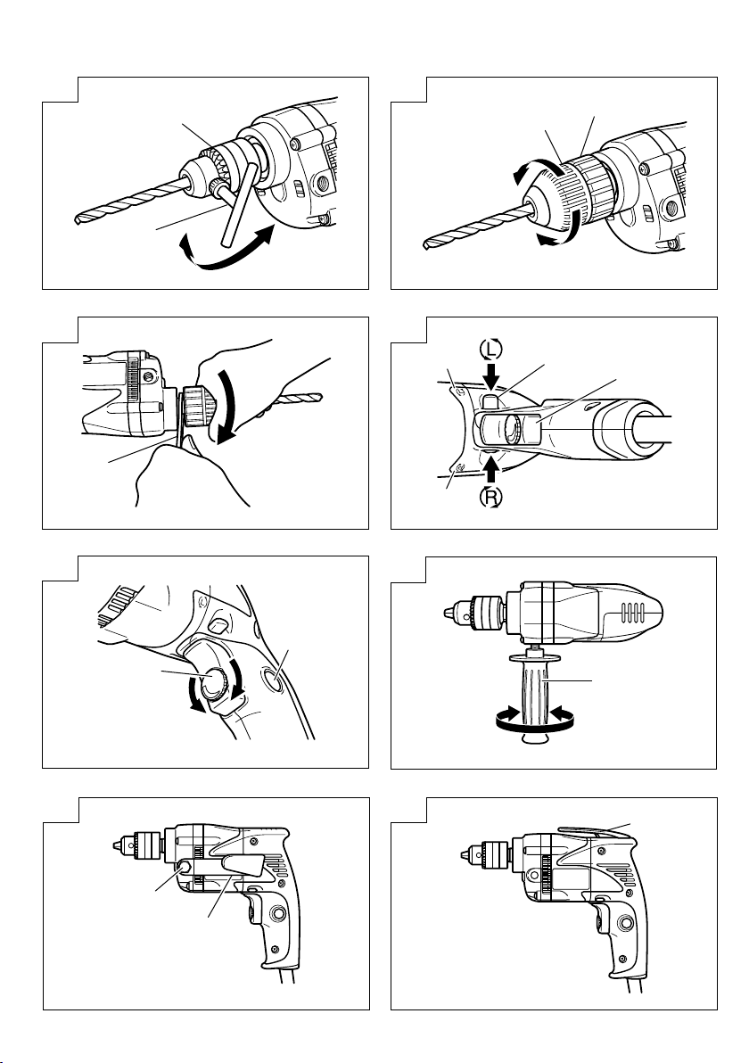
5. Mounting and dismounting of the bit
For keyed chuck (Fig. 1)
(1) Open the chuck jaws, and insert the bit into the
chuck.
(2) Place the chuck wrench in each of the three holes
in the chuck, and turn it in the clockwise direction
(viewed from the front side). Tighten securely.
(3) To remove the bit, place the chuck wrench into one
of the holes in the chuck and turn it in the
counterclockwise direction.
For keyless chuck (Fig. 2)
(1) Open the chuck jaws, and insert the bit into the
chuck.
To open the chuck jaws, hold the ring while turning
the sleeve in the counterclockwise direction (viewed
from the front side).
(2) Firmly grasp the ring and turn the sleeve in the
clockwise direction. Tighten securely.
(3) To remove the bit, firmly grasp the ring and turn
the sleeve in the counterclockwise direction.
(4) If it is hard to loosen the sleeve, fix the spindle
using the open-end wrench, hold the sleeve firmly,
and turn it in the loosening direction
(counterclockwise when viewed from the front).
(Fig. 3)
6. Check the rotational direction (Fig. 4)
The bit rotates clockwise (viewed from the rear
side) by pushing the R-side of the push button.
The L-side of the push button is pushed to turn the
bit counterclockwise.
(The
and R marks are provided on the body.)
7. Installing the side handle (Optional accessory)
8. Attaching the hook. (Optional accessory)
CAUTION:
䡬 Before hanging the main unit from the waist belt,
L
A Side handle can be installed on either side of
the tool for right or left handed use.
To install the side handle, thread it into the socket
on the desired side of the gear cover and tighten
it securely. (Fig. 6)
For hook (side-attaching) (Fig. 7)
Fix the hook firmly on the desired side of the gear
cover using M10 bolt which is supplied with hook.
For hook (A) (top-attaching) (Fig. 8)
To attach the hook (A), it is necessary to disassemble
the handle portion which covered the tool’s electrical
system. For your continued safety and electrical
shock protection, installing the hook (A) on this drill
should ONLY be performed by a HiKOKI
AUTHORIZED SERVICE CENTER.
When the power tool is used with a hook fixed to
it, pay attention to the following points:
make sure that the drill has come to a complete
stop.
4
Page 6

English
While it is suspended from the waist belt, the power
plug must be disconnected from the power source.
䡬 Do not walk about with the power tool hanging
from the waist belt.
䡬 In the case of operation in a high place, it is
dangerous to drop the tool accidentally. If the hook
is deformed or hung from the wrong position, there
is danger that the hook will slip off and the tool
will fall.
Be careful to avoid danger.
䡬 In making a through hole, the power tool sometimes
shakes violently when the workpiece is pierced,
from example. Be careful you are not hurt by the
hook even if such situation happens.
HOW TO USE
1. Switch operation
䡬 When the trigger is depressed, the tool rotates.
When the trigger is released, the tool stops.
䡬 The rotational speed of the drill can be controlled
by varying the amount that the trigger switch is
pulled. Speed is low when the trigger switch is
pulled slightly and increases as the trigger switch
is pulled more.
䡬 The desired rotation speed can be pre-selected with
the speed control dial.
Turn the speed control dial clockwise for higher
speed and counterclockwise for lower speed.
(Fig. 5)
䡬 Pulling the trigger and pushing the stopper, it keeps
the switched-on condition which is convenient for
continuous running. When switching off, the stopper
can be disconnected by pulling the trigger again.
2. Drilling
䡬 When drilling, start the drill slowly, and gradually
increasing speed as you drill.
䡬 Always apply pressure in a straight line with the
bit. Use enough pressure to keep drilling, but do
not push hard enough to stall the motor or deflect
the bit.
䡬 To minimize stalling or breaking through the
material, reduce pressure on drill and ease the bit
through the last part of the hole.
䡬 If the drill stalls, release the trigger immediately,
remove the bit from the work and start again. Do
not click the trigger on and off in an attempt to
start a stalled drill. This can damage the drill.
䡬 The larger the drill bit diameter, the larger the
reactive force on your arm.
Be careful not to lose control of the drill because
of this reactive force.
To maintain firm control, establish a good foothold,
use side handle, hold the drill tightly with both
hands, and ensure that the drill is vertical to the
material being drilled.
2.
Inspecting the mounting screws
Regularly inspect all mounting screws and ensure
that they are properly tightened. Should any of the
screws be loose, retighten them immediately. Failure
to do so could result in serious hazard.
3.
Maintenance of the motor
The motor unit winding is the very “heart” of the
power tool. Exercise due care to ensure the winding
does not become damaged and/or wet with oil or
water.
4.
Inspecting the carbon brushes
For your continued safety and electrical shock
protection, carbon brush inspection and replacement
on this tool should ONLY be performed by a HiKOKI
AUTHORIZED SERVICE CENTER.
NOTE
Due to HiKOKI’s continuing program of research and
development, the specifications herein are subject to
change without prior notice.
MAINTENANCE AND INSPECTION
1. Inspecting the drill bits
Since use of an abraded drill bits will cause motor
malfunctioning and degraded efficiency, replace the
drill bits with a new one or resharpening without
delay when abrasion is noted.
5
Page 7

Español
PRECAUCIONES GENERALES PARA
OPERACIÓN
¡ADVERTENCIA! Cuando utilice herramientas eléctricas,
tome las medidas de seguridad básicas para reducir el
riesgo de incendios, descargas eléctricas, y lesiones,
incluyendo lo siguiente. Lea todas todas estas
instrucciones antes de utilizar este producto y guárdelas.
Para realizar operaciones seguras:
1. Mantener el área de trabajo limpia, áreas y bancos
de trabajo desordenados son causa de daños
personales.
2. Considerar el medio ambiente del área de trabajo.
No exponer las herramientas eléctricas a la lluvia.
No usar herramientas eléctricas en lugares
mojados o húmedos. Mantener el área de trabajo
bien iluminada.
No utilice herramientas eléctricas cuando exista
el riesgo de incendios o de explosión.
3. Protegerse contra descargas eléctricas. Evitar el
contacto del cuerpo con las superficies puestas
a tierra. (p. ej., tubos, radiadores, hornos de
microondas, o refrigeradores.)
4. Mantener a los niños alejados. No dejar que los
visitantes toquen las herramientas ni los cables
de extensión. Todos los visitantes deberán
mantenerse alejados del área de trabajo.
5. Guardar las herramientas que no se usen y
ponerlos en lugares secos, altos o cerrados, fuera
del alcance de los niños.
6. No forzar las herramientas, éstas trabajarán más
y con mayor seguridad cuando cumplan con las
especificaciones para las cuales fueron diseñadas.
7. Usar las herramientas apropiadas. No forzar
pequeñas herramientas o accesorios a realizar el
trabajo de herramientas de mayor potencia. No
utilizar herramientas para otros propósitos para
los cuales no fueron diseñadas, por ejemplo, no
utilizar sierras circulares para cortar ramas de
árboles o troncos.
8. Vestir apropiadamente. No ponerse ropas que
queden flojas ni tampoco joyas. Estas podrian
quedar atrapadas en las partes móviles de las
herramientas. Cuando se trabaje en exteriores, se
recomienda el uso de guantes de goma y calzado
que no resbale.
9. Usar gafas de protección. Usar también mascarillas
contra el polvo si las condiciones de corte fuesen
polvorientas.
10. Conecte un equipo colector de polvo.
Si existen dispositivos para la conexión de equipos
de extracción y recolección de polvo, cerciórese
de que éstos estén conectados adecuadamente,
y de utilizarlos en la forma correcta.
11. Cuidar del cable. Nunca lleve las herramientas
colgando del cable, tampoco tire del cable para
efectuar la desconexión de las herramientas.
Mantener el cable alejado del calor, aceite y bordes
agudos.
12. Asegurar la pieza de trabajo usando para ello
abrazaderas o un tornillo. Esto es más seguro que
usar las manos, ademas, ambas manos quedan
libres para operar la herramienta.
13. No extenderse excesivamente para efectuar un
trabajo. Mantener en todo momento un buen
balance y base de apoyo.
14. Mantener cuidadosamente las herramientas.Tener
las siempre limpias y afiladas para obtener un
mejor rendimiento y un funcionamiento más
seguro. Seguir siempre las instrucciones para la
lubricación y el cambio de accesorios. Inspeccionar
periódicamente los cables de las herramientas y
si estuviesen danãdos, hacer que los reparen
técnicos ó expertos. Inspeccionar periodicamente
los cables de extensión y cambiarlos si estuviesen
dañados. Mantener los mangos secos, limpios, y
libres de aceite y grasa.
15. Desconectar las herramientas cuando no se usen,
antes de repararlas, y cuando se cambien
accesorios como por ejemplo, cuchillas, brocas,
cortadores, etc.
16. Quitar las cuñas y las llaves de tuercas.
Acostumbrarse a comprobar si se han quitado las
cuñas y las llaves de tuercas antes de poner las
herramientas en funcionamiento.
17. Evitar puestas en funcionamiento sin fin alguno.
No llevar las herramientas con los dedos en los
inerruptores mientras que éstas están conectadas.
Cuando se conecten las herramientas, cerciorarse
de que los interruptores esten en la posición de
desconectados.
18. Para usos en exteriores usar cables de extensión.
Cuando las herramientas vayan a ser usadas en
exteriores, usar solamente cables de extensión
diseñados para tal propósito.
19. Estar siempre alerta y poner atención a lo que
se está haciendo, usar el sentido común y no
operar con la herramienta cuando se esté cansado.
20. Comprobar las piezas dañadas. Antes de seguir
con el funcionamiento de las herramientas, las
piezas que estén dañadas deberán comprobarse
cuidadosamente para determinar si pueden
funcionar apropiadamente y cumplir con la función
para las que fueron diseñadas. Comprobar el
alineamiento y agarrotamiento de piezas móviles,
rotura de piezas, montura, y cualiquier otra
anormalia que pudiese afectar al rendimiento de
la herramienta. Cualquier pieza que estuviese
dañada deberá repararse apropiadamente o
cambiarse en un centro de reparaciones autorizado,
al menos que se indique, lo contrario en este
manual de instrucciones. Procurar que los
interruptores defectuosos los cambie un centro de
reparaciones autorizado.
No usar las herramientas si sus interruptores no
funcionasen apropiadamente.
21. Advertencia
La utilización de cualquier accesorio o aditivo no
recomendado en este manual de instrucciones
puede conducir al riesgo de lesiones.
22. En caso de avería, haga que su herramienta sea
reparada por un técnico cualificado.
Esta herramienta eléctrica está de acuerdo con los
requisitos de seguridad pertinentes. Las
reparaciones solamente deberán realizarlas
técnicos cualificados utilizando piezas de repuesto
originales. De lo contrario, el usuario podría
lesionarse.
PRECAUCIONES AL UTILIZAR EL TALADRO
1. Sujete firmemente el taladro durante el uso.
2. No utilice guantes hechos de un material que se
pueda enrollar, como algodón, lana, paño, cordón,
etc.
3. Antes de taladrar paredes, techos o pisos, asegúrese
de que no hayan cables o conductos eléctricos en
el interior.
6
Page 8

Español
ESPECIFICACIONES
Voltaje (por áreas)* (110V, 120V, 127V, 220V, 230V, 240V)
Acometida 680W*
Velocidad de marcha en vacío 0–2500min
Capacidad del portabrocas 10 mm
Acero Broca de torsión 10 mm
Capacidad
Peso (sin cable) 1,4 kg
*Verificar indefectiblemente los datos de la placa de características de la máquina, pues varían de acuerdo al país de
destino.
Madera
ACCESORIOS ESTANDAR
䡬 Velvedor de mandril (Especificaciones sólo para
portabrocas sin llave) .............................................. 1
Accesorios estándar están sujetos a cambio sin previo
aviso.
ACCESORIOS FACULTATIVOS
(1) Asa lateral
(2) Gancho
(3) Gancho (A)
Accesorios facultativos están sujetos a cambio sin previo
aviso.
APLICACIONES
䡬 Por acción de orificios en metal, madera y plástico.
ANTES DE LA PUESTA EN MARCHA
1. Alimentación
Asegurarse de que la acometida de red que ha de
ser utilizada es conforme a las exigencias de
corriente especificadas en la placa de características
del producto.
2. Conmutador de alimentación
Asegurarse de que el conmutador de acometida
está en posición OFF (desconectado). Si el enchufe
está conectado a la caja del enchufe mientras el
conmutador de acometida está en posición ON
(conectado) la herramienta eléctrica empezará a
trabajar inmediatamente, provocando un serio
accidente.
3. Cable de prolongación
Cuando está alejada el área de trabajo de la red
de acometida, usar un cable de prolongación de un
grosor suficiente y potencia nominal. El cable de
prolongación debe ser mantenido o más corto
posible.
4. Seleccionar la broca de taladro apropiada
䡬 Perforando metal o plástico
Usar una broca de taladro ordinaria para trabajos
en metal.
Broca de horquilla plana
Broca de berbiquí 16 mm
䡬 Perforando madera
Usar una broca de taladro ordinaria para trabajos
en madera. En cualquier caso, perforando orificios
de 6,5 mm, o menos, usar una broca de taladro
para trabajos en metal.
5. Montaje y desmontaje de la broca
Para portabrocas con llave (Fig. 1)
(de venta por separado)
(1) Abra las mordazas del portabrocas e inserte la
broca en el portabrocas.
(2) Coloque la llave del portabrocas en cada uno de
los tres orificios del portabrocas, y gírela en el
sentido de las agujas del reloj (visto desde el lado
delantero). Apriete firmemente.
(3) Para sacar la broca, coloque la llave del portabrocas
en uno de los orificios del portabrocas y gírela en
el sentido contrario a las agujas del reloj.
Para portabrocas sin llave (Fig. 2)
(1) Abra las mordazas del portabrocas e inserte la
broca en el portabrocas.
Para abrir las mordazas del portabrocas, sujete el
anillo mientras gira el manguito en el sentido
contrario a las agujas del reloj (visto desde el lado
delantero).
(2) Sujete el anillo firmemente y gire el manguito en
el sentido de las agujas del reloj. Apriete firmemente.
(3) Para sacar la broca, sujete el anillo firmemente y
gire el manguito en el sentido contrario a las agujas
del reloj.
(4) Si no consigue aflojar el manguito, fije el husillo
utilizando una llave fija, sujete el manguito
firmemente y gírelo en la dirección de aflojamiento
(en sentido contrario a las agujas del reloj visto
desde adelante). (Fig. 3)
6. Verifique la dirección de rotación (Fig. 4)
La broca gira en el sentido de las agujas del reloj
(visto desde el lado trasero) empujando el lado R
del botón.
Si empuja el lado L del botón, la broca girará en
sentido contrario a las agujas del reloj.
(Las marcas
7. Instalación del asa lateral (Accesorio opcional)
Es posible insertar un asa lateral sobre uno u otro
lado de la herramienta, según que el usuario sea
diestro o zurdo.
Para instalar el asa lateral, enrósquelo en el casquillo
del lado deseado de la cubierta de engranajes, y
apriételo firmemente. (Fig. 6)
L
–1
25 mm
y R están provistas en el cuerpo).
7
Page 9

Español
8. Fijación del gancho. (Accesorio opcional)
Para el gancho (fijación lateral) (Fig. 7)
Fije firmemente el gancho sobre el lado deseado
de la cubierta de engranajes utilizando el perno
M10 entregado con el gancho.
Para el gancho (A) (fijación superior) (Fig.8)
Para fijar el
parte del asa que cubre el sistema eléctrico de la
herramienta. Para poder utilizar la herramienta en
condiciones de seguridad y evitar las descargas
eléctricas, la instalación del gancho (A) de este
taladro debe ser realizado SÓLO por un CENTRO
DE SERVICIO AUTORIZADO HiKOKI.
PRECAUCIÓN
Cuando utilice la herramienta eléctrica con un
gancho fijado, preste atención a los puntos
siguientes:
䡬 Antes de colgar la unidad del cinturón, cercióre de
que el taladro esté completamente parado.
Cuando tenga el taladro colgado del cinturón, el
enchufe de alimentación deberá estar desconectado
de la fuente de alimentación.
䡬 Ne camine con la herramienta eléctrica colgada del
cinturón.
䡬 Cuando trabaje en un lugar elevado, será peligroso
el dejar caer accidentalmente la herramienta. Si el
gancho está deformado o en posición errónea, existe
el peligro de que se deslice y que se caiga la
herramienta.
Tenga cuidado para evitar peligros.
䡬 Cuando taladre orificios, es posible que la
herramienta sufra sacudidas violentas, por ejemplo,
se parta la pieza de trabajo. Tenga cuidado de no
herirse con el gancho en caso de ocurrir esta
situación.
gancho (A), es necesario desarmar la
COMO SE USA
1. Operación del interruptor
䡬 La herramienta gira al presionar el interruptor de
gatillo. Al soltar el gatillo, la herramienta se detiene.
䡬 La velocidad de rotación del taladro puede
controlarse variando la fuerza de apriete del
interruptor de gatillo.
Apretando ligeramente el interruptor de gatillo la
velocidad es lenta, pero aumenta mientras más se
lo aprieta.
䡬 Es posible seleccionar previamente la velocidad de
rotación deseada con el dial de control de velocidad.
Gire el dial de control de velocidad en el sentido
a las agujas del reloj para aumentar la velocidad,
y en sentido contrario para disminuirla. (Fig. 5).
䡬 Tire del gatillo y empuje el tope para mantener
activada la alimentación, lo cual es conveniente
para un funcionamiento continuo. Cuando se lo
desconecta, el tope puede quitarse tirando del gatillo
otra vez.
2. Taladrado
䡬 Para taladrar, inicie el taladro lentamente, y aumente
gradualmente la velocidad.
䡬 Siempre aplique presión en línea recta a la broca.
Aplique una presión suficiente para seguir
taladrando, pero no empuje con una fuerza tal que
pueda provocar el calado del motor o la desviación
de la broca.
䡬 Para reducir al mínimo el calado o la rotura a través
del material, disminuya la presión aplicada al taladro
y mueva la broca a través de la última parte del
orificio.
䡬 Si el taladro se atasca, suelte inmediatamente el
gatillo, saque la broca de la pieza de trabajo y
empiece otra vez. No haga clic en el gatillo para
conectarlo y desconectarlo con la intención de poner
en marcha el taladro atascado, pues se podrá dañar
el taladro.
䡬 Cuanto mayor sea el diámetro de la broca de taladro,
mayor será la fuerza de reacción sobre su brazo.
Asegúrese de no perder el control del taladro debido
a esta fuerza de fricción.
Para mantener un control firme, haga pie firme,
utilice el asa lateral, sujete el taladro firmemente
con ambas manos, y asegúrese de mantener el
taladro vertical con respecto al material que se está
taladrando.
MANTENIMIENTO E INSPECCION
1. Inspección de las brocas de barrena
Debido a que el uso de brocas de barrena
desgastadas producen fallos de funcionamiento del
motor y una disminución de la eficiencia, cámbielas
inmediatamente por otras nuevas o reafílelas cuando
note abrasión en las mismas.
2. Inspeccionar la broca de taladro y el macho de
roscar
Como el uso continuado de una broca o macho de
roscar desgastados disminuye la eficiencia operativa
y causa un posible recalentamiento del motor,
reemplazar o afilar la broca o el macho sin demora
si se nota un excesivo desgaste.
3. Mantenimiento del motor
La unidad de devanado del motor es el verdadero
“corazón” del herramientas eléctricas. Prestar el
mayor cuidado a asegurarse de que el devando no
se dañe y/o se humedezca con aceite o agua.
4. Inspección de las escobillas
Por motivos de seguridad contra
eléctricas, la inspección y el reemplazo de las
escobillas deberán realizarse SOLAMENTE en un
CENTRO DE SERVICIO AUTORIZADO POR HiKOKI.
OBSERVACION
Debido al programa continuo de investigación y desarollo
de HiKOKI estas especificaciones están sujetas a cambio
sin preaviso.
descargas
8
Page 10

Part Name Q’TY
Item
No.
2
2
D4×30
TAPPING SCREW (W/FLANGE)
1 CHUCK WRENCH 10TL2 1
3 RETAINING RING FOR D32 HOLE 1
4 SPINDLE 1
2-1 DRILL CHUCK 10TLRA 1
5
2-2 DRILL CHUCK 10TLRH-N 1
D4×45
TAPPING SCREW (W/FLANGE)
6 BALL BEARING 6002VVCMPS2L 1
7 RETAINING RING FOR D15 SHAFT 1
9 GEAR COVER 1
8
10 GEAR 1
11 INNER COVER 1
12 BALL BEARING 608VVC2PS2L 2
13 ARMATURE 1
14 FAN GUIDE 1
15 TAPPING SCREW D4×45 2
16 STATOR 1
17 HOUSING 1
3
TAPPING SCREW (W/FLANGE)
D4×20
18 NAME PLATE 1
19 INTERNAL WIRE (BROWN) 100L 1
20 INTERNAL WIRE (BLUE) 55L 1
21
22 HANDLE COVER 1
23 SWITCH 1
1
2
TAPPING SCREW (W/FLANGE)
D4×16
BRAND LABEL
24 PUSHING BUTTON 1
28
25 CARBON BRUSH 2
26 BRUSH HOLDER 2
27
29 CORD CLIP 1
30 CORD ARMOR 1
31 CORD 1
501 CASE 1
9
Page 11

10
Page 12

Issued by
Shinagawa Intercity Tower A, 15-1, Konan 2-chome,
Minato-ku, Tokyo 108-6020, Japan
Distribuido por
Calle Isaac Newton No.286, 2do Piso, Col. Polanco V Sección,
Del. Miguel Hidalgo, C. P. 11560
Ciudad de México, México.
Code No. C99120142 F
Printed in China
806
 Loading...