

Page 1
Reciprocating Saw
Model CR 13VBY
Handling instructions
NOTE:
Before using this Electric Power Tool, carefully read through these
HANDLING INSTRUCTIONS to ensure efficient, safe operation. It is
recommended that these INSTRUCTIONS be kept readily available
as an important reference when using this power tool.
Page 2

Symbols
When symbols are used on the machine, refer to the
followings to understand the meaning.
V ................... volts
A .................. amperes
Hz ................. hertz
W ................. watts
kW ................ kilowatts
g ................... grams
kg ................. kilograms
min .............. minutes
s ................... seconds
n
................ no-load speed
0
---/min or ---/min
—
or d.c. .................. direct current
---
or a.c. ................. Alternating current
.......................... class II tool
.............. WARNING– To reduce the risk of injury,
-1
Revolutions or reciprocations per
......
minute
user must read instruction manual.
3) Personal safety
GENERAL POWER TOOL SAFETY WARNINGS
WARNING
Read all safety warnings and all instructions.
Failure to follow the warnings and instructions may result in
electric shock, fire and/or serious injury.
Save all warnings and instructions for future reference.
The term “power tool” in the warnings refers to your mainsoperated (corded) power tool or battery-operated (cordless)
power tool.
1) Work area safety
a) Keep work area clean and well lit.
Cluttered or dark areas invite accidents.
b) Do not operate power tools in explosive atmospheres,
such as in the presence of flammable liquids, gases
or dust.
Power tools create sparks which may ignite the dust
or fumes.
c) Keep children and bystanders away while operating
a power tool.
Distractions can cause you to lose control.
2) Electrical safety
a) Power tool plugs must match the outlet.
Never modify the plug in any way.
Do not use any adapter plugs with earthed (grounded)
power tools.
Unmodified plugs and matching outlets will reduce
risk of electric shock.
b) Avoid body contact with earthed or grounded surfaces,
such as pipes, radiators, ranges and refrigerators.
There is an increased risk of electric shock if your
body is earthed or grounded.
c) Do not expose power tools to rain or wet conditions.
Water entering a power tool will increase the risk of
electric shock.
d) Do not abuse the cord. Never use the cord for carrying,
pulling or unplugging the power tool.
Keep cord away from heat, oil, sharp edges or moving
parts.
Damaged or entangled cords increase the risk of
electric shock.
e) When operating a power tool outdoors, use an
extension cord suitable for outdoor use.
1
4) Power tool use and care
Use of a cord suitable for outdoor use reduces the
risk of electric shock.
f) If operating a power tool in a damp location is
unavoidable, use a residual current device (RCD)
protected supply.
Use of an RCD reduces the risk of electric shock.
a) Stay alert, watch what you are doing and use common
sense when operating a power tool.
Do not use a power tool while you are tired or under
the influence of drugs, alcohol or medication.
A moment of inattention while operating power tools
may result in serious personal injury.
b) Use personal protective equipment. Always wear eye
protection.
Protective equipment such as dust mask, non-skid
safety shoes, hard hat, or hearing protection used for
appropriate conditions will reduce personal injuries.
c) Prevent unintentional starting. Ensure the switch is
in the off-position before connecting to power source
and/or battery pack, picking up or carrying the tool.
Carrying power tools with your finger on the switch
or energising power tools that have the switch on
invites accidents.
d) Remove any adjusting key or wrench before turning
the power tool on.
A wrench or a key left attached to a rotating part of
the power tool may result in personal injury.
e) Do not overreach. Keep proper footing and balance
at all times.
This enables better control of the power tool in
unexpected situations.
f) Dress properly. Do not wear loose clothing or
jewellery. Keep your hair, clothing and gloves away
from moving parts.
Loose clothes, jewellery or long hair can be caught
in moving parts.
g) If devices are provided for the connection of dust
extraction and collection facilities, ensure these are
connected and properly used.
Use of dust collection can reduce dust related hazards.
a) Do not force the power tool. Use the correct power
tool for your application.
The correct power tool will do the job better and safer
at the rate for which it was designed.
b) Do not use the power tool if the switch does not
turn it on and off.
Any power tool that cannot be controlled with the
switch is dangerous and must be repaired.
c) Disconnect the plug from the power source and/or
the battery pack from the power tool before making
any adjustments, changing accessories, or storing
power tools.
Such preventive safety measures reduce the risk of
starting the power tool accidentally.
d) Store idle power tools out of the reach of children
and do not allow persons unfamiliar with the power
tool or these instructions to operate the power tool.
Power tools are dangerous in the hands of untrained
users.
e) Maintain power tools. Check for misalignment or
binding of moving parts, breakage of parts and any
other condition that may affect the power tool's
operation.
If damaged, have the power tool repaired before use.
Many accidents are caused by poorly maintained
power tools.
Page 3

f) Keep cutting tools sharp and clean.
Properly maintained cutting tools with sharp cutting
edges are less likely to bind and are easier to control.
g) Use the power tool, accessories and tool bits etc.
in accordance with these instructions, taking into
account the working conditions and the work to be
performed.
Use of the power tool for operations different from
those intended could result in a hazardous situation.
5) Service
a) Have your power tool serviced by a qualified repair
person using only identical replacement parts.
This will ensure that the safety of the power tool is
maintained.
PRECAUTION
Keep children and infirm persons away.
When not in use, tools should be stored out of reach of children
and infirm persons.
RECIPROCATING SAW SAFETY WARNING
1. Hold power tool by insulated gripping surfaces, when
performing an operation where the cutting accessory
may contact hidden wiring or its own cord. Cutting
accessory contacting a "live" wire may make exposed
metal parts of the power tool "live" and could give
the operator an electric shock.
SPECIFICATIONS
Voltage (by areas)* (110 V, 115 V, 120 V, 127 V, 220 V, 230 V, 240 V)
Power Input 1150 W*
Capacity Mild Steel Pipe: O.D. 130 mm
No-Load Speed 0 – 3000 /min
Stroke 32 mm
Weight (without cord) 4.4 kg
* Be sure to check the nameplate on product as it is subject to change by areas.
STANDARD ACCESSORIES
(1) Blade (No. 341) .................................................... 1
(2) Case ........................................................................ 1
Standard accessories are subject to change without
notice.
OPTIONAL ACCESSORIES (sold separately)
(1) No. 1 Blade (12) No. 103 Blade
(2) No. 2 Blade (13) No. 104 Blade
(3) No. 3 Blade (14) No. 105 Blade
(4) No. 4 Blade (15) No. 106 Blade
(5) No. 5 Blade (16) No. 107 Blade
(6) No. 8 Blade (17) No. 108 Blade
(7) No. 9 Blade (18) No. 121 Blade
(8) No. 95 Blade (19) No. 131 Blade
(9) No. 96 Blade (20) No. 132 Blade
(10) No. 101 Blade
(11) No. 102 Blade
䡬 (1) – (9) : HCS Blades (HCS : Highspeed Carbon Steel)
䡬 (10) – (20) : Bl-METAL Blades
Refer to Table 1, 2 and 3 for use of the blades.
Optional accessories are subject to change without notice.
APPLICATIONS
䡬 Cutting pipe and angle steel.
䡬 Cutting various lumbers.
䡬 Cutting mild steel plates, aluminum plates, and copper
plates.
䡬 Cutting synthetic resins, such as phenol resin and
vinyl chloride.
Vinyl Chloride Pipe: O.D. 130 mm
Wood: Depth 300 mm
Mild Steel Plate: Thickness 19 mm
For details refer to the section entitled “SELECTION OF
BLADES”.
PRIOR TO OPERATION
1. Power source
Ensure that the power source to be utilized conforms
to the power requirement specified on the product
nameplate.
2. Power switch
Ensure that the power switch is in the OFF position. If
the plug is connected to a receptacle while the power
switch is in the ON position, the power tool will start
operating immediately, which could cause a serious
accident.
3. Extension cord
When the work area is removed from the power
source, use an extension cord of sufficient thickness
and rated capacity. The extension cord should be kept
as short as practicable.
4. Dust produced in operation
The dust produced in normal operation may affect
the operator’s health. To wear a dust mask is
recommended.
5. Mounting the blade
This unit employs a detachable mechanism that
enables mounting and removal of saw blades without
the use of a wrench or other tools.
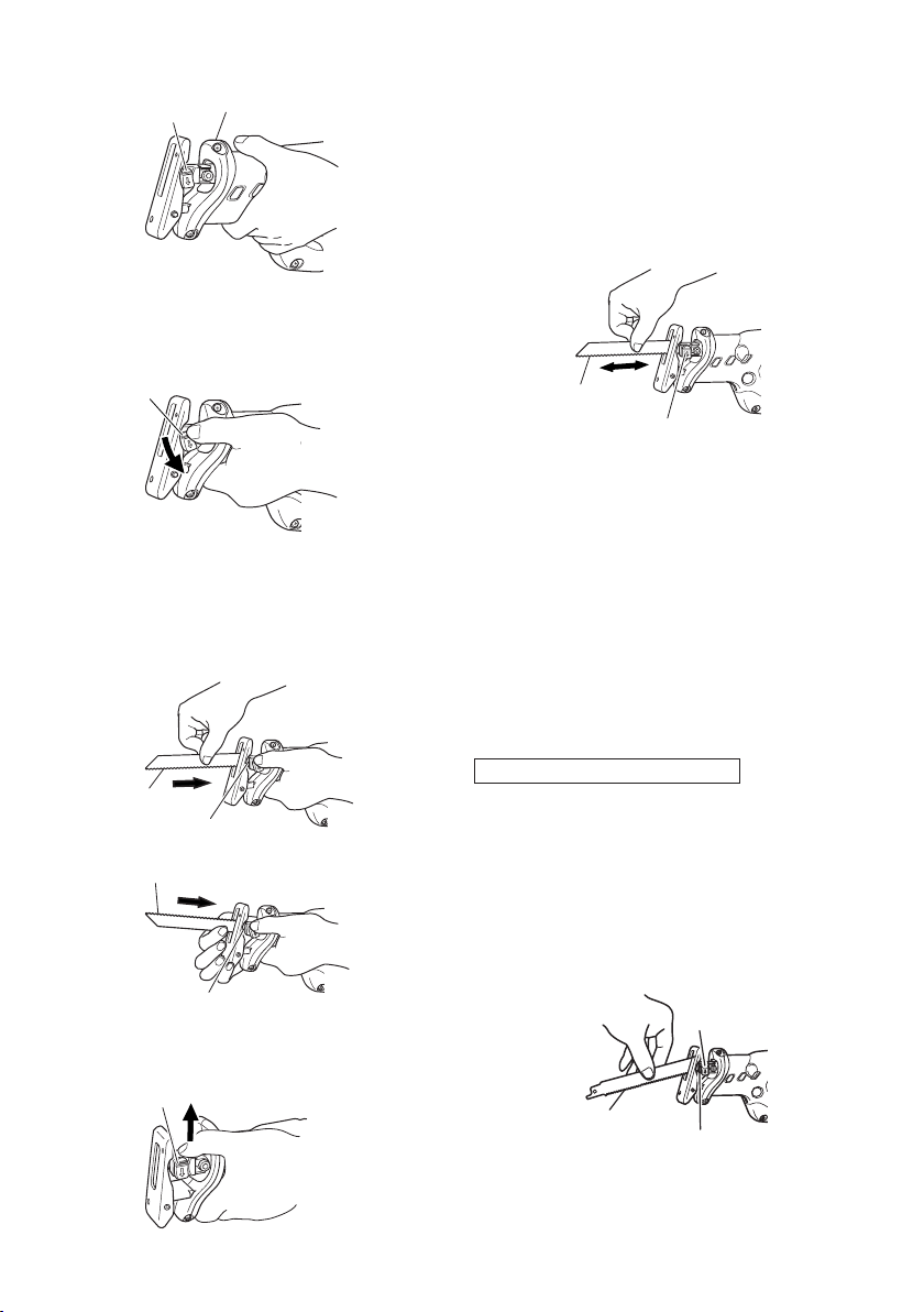
(1) Turn on and off the switching trigger several times
so that the lever can jump out of the front cover
completely. Thereafter, turn off the switch and unplug
the power cord. (Fig. 1)
CAUTION
Be absolutely sure to keep the switch turned off and
the power cord unplugged to prevent any accident.
2
Page 4
Front cover
Lever
Fig. 1
(2) Push the lever in the direction of the arrow mark
shown in Fig. 2 marked on the lever.
Lever
Fig. 2
(3) Insert the saw blade all the way into the small slit of
the plunger tip with the lever pushing. You can mount
this blade either in the upward or downward direction.
(Fig. 3, Fig. 4)
Blade
Slit of plunger
Blade
Slit of plunger
(4) When you release the lever, the spring force will return
the lever to the correct position automatically. (Fig. 5)
Lever
Fig. 3
Fig. 4
(5) Pull the back of the saw blade two or three times by
hand and check that the blade is securely mounted.
When pulling the blade, you will know it is properly
mounted if it clicks and the lever moves slightly.
(Fig. 6)
CAUTION
When pulling the saw blade, be absolutely sure to
pull it from the back. Pulling other parts of the blade
will result in an injury.
Blade
Lever
Fig. 6
6. Dismounting the blade
(1) Turn on and off the switching trigger several times so
that the lever can jump out of the front cover
completely. Thereafter, turn off the switch and unplug
the power cord. (Fig. 1)
CAUTION
Be absolutely sure to keep the switch turned off and
the power cord unplugged to prevent any accident.
(2) After you have pushed the lever in the direction of
the arrow mark shown in Fig. 2, turn the blade so it
faces downward. The blade should fall out by itself. If
the blade doesn’t fall out, pull it out by hand.
CAUTION
Never touch the saw blade immediately after use. The
metal is hot and can easily burn your skin.
WHEN THE BLADE IS BROKEN
Even when the saw blade is broken and remains inside
the small slit of the plunger, it should fall out if you
push the lever in the direction of the arrow mark, and
face the blade downward. If it doesn’t fall out itself,
take it out using the procedures explained below.
(1) If a part of the broken saw blade is sticking out of the
small slit of the plunger, pull out the protruding part
and take the blade out.
(2) If the broken saw blade is hidden inside the small slit,
hook the broken blade using a tip of another saw blade
and take it out. (Fig. 7)
Lever
Another blade
Slit of plunger
Fig. 7
Fig. 5
3
Page 5

MAINTENANCE AND INSPECTION OF SAW BLADE
MOUNT
(1) After use, blow away sawdust, earth, sand, moisture,
etc., with air or brush them away with a brush, etc., to
ensure that the blade mount can function smoothly.
(2) As shown in Fig. 8, carry out lubrication around the
blade holder on a periodic basis by use of cutting fluid,
etc.
Blade holder
Lever
(1) Press a pushbutton. When you do this, a base lever
will jump out to prepare the base for adjustment.
(Fig. 11)
Push button
Base lever
Machine oil
NOTE:
Continued use of the tool without cleaning and
lubricating the area where the saw blade is installed
can result in some slack movement of the lever due
to accumulated sawdust and chips. Under the
circumstances, pull a rubber cap provided on the lever
in the direction of an arrow mark as shown in Fig. 9
and remove the rubber cap from the lever. Then, clean
up the inside of the blade holder with air and the like
and carry out sufficient lubrication. The rubber cap
can be fitted on if it is pressed firmly onto the lever.
At this time, make certain that there exists no
clearance between the blade holder and the rubber
cap, and furthermore ensure that the saw-bladeinstalled area can function smoothly.
Lever
Rubber cap
CAUTION:
Do not use any saw blade with a worn-out blade hole.
Otherwise, the saw blade can come off, resulting in
personal injury. (Fig. 10)
7. Adjusting the base
This unit employs a mechanism that can adjust the
base mounting position in three stages without the
use of a wrench or other tools.
Fig. 8
Fig. 9
Blade hole
Blade
Fig. 10
Fig. 11
2) Push up the base tip and jog the base back and forth.
(Fig. 12)
Base
Fig. 12
(3) You can adjust the base position in three stages. Move
the base at an interval of about 15 mm, find the
position where the base hooks, and press in the base
lever with your fingers. The base is secured when you
hear the clicking sound. (Fig. 13)
Base lever
8. Adjusting the blade reciprocating speed
This unit has a built-in electronic control circuit that
makes it possible to adjust the variable speed of the
saw blade either both by pulling a switching trigger
or turning a dial. (Fig. 14)
Fig. 13
4
Page 6

Switch trigger
Graduation
Dial
Fig. 14
(1) If you pull the trigger further in, the speed of the blade
accelerates. Begin cutting at a low speed to ensure
the accuracy of your target cut position. Once you’ve
obtained a sufficient cutting depth, increase the
cutting speed.
(2) On the dial scale, “5” is the maximum speed and “1”
the minimum. The high speed is generally suitable
for soft materials such as wood, and the low speed is
suitable for hard materials such as metal. We
recommend that you use the following as a rough
guide in selecting the suitable speed for the materials
you are cutting.
Example of materials Recommended
to be cut dial scale
Mild steel pipes /
cast-iron tubes / 2 – 4
L-shaped angle steel
Wood / wood with nails
driven in
Stainless steel 1 – 3
Aluminum / brass / copper 2 – 4
Plaster board 4 – 5
Plastic / fiber board 1 – 3
CAUTION
䡬 When cutting at low speed (scale of 1 – 2), never cut a
wooden board more than 10 mm thick or a mild steel
plate more than 2 mm thick. The load on the motor
can result in overheating and damage.
䡬 Although this unit employs a powerful motor,
prolonged use at a low speed will increase the load
unduly and may lead to overheating. Properly adjust
the saw blade to allow steady, smooth cutting
operation, avoiding any unreasonable use such as
sudden stops during cutting operation.
9. Adjusting the swing cutting operation
Two cutting systems can be selected with this unit.
The first is straight cutting, in which the saw blade is
moved linearly, and the second is the swing cutting,
in which the saw blade is swung like a pendulum.
(Fig. 15, Fig. 16)
(1) Straight cutting
You can perform straight cutting by setting the change
lever widthwise. Straight cutting should normally be
performed when cutting hard materials such as metal,
etc. (Fig. 15)
5
5
Straight cutting
Fig. 15
(2) Swing cutting
You can perform swing cutting by setting the change
lever lengthways. Swing cutting should normally be
performed when cutting soft materials such as wood,
etc.
Swing cutting is efficient since the saw blade forcibly
bites into the material. (Fig. 16)
You can cut efficiently by swing cutting, mounting the
saw blade in whichever direction, upward or
downward.
Swing cutting
CAUTION
䡬 Even for soft materials, you should perform straight
cutting if you wish to make curved or clean cuts.
䡬 Dust and dirt accumulated on the change lever section
can degrade the function of the change lever.
Periodically clean the change lever section.
䡬 When performing swing cutting, use a saw with
straight blade. If a saw with curved blade is used, the
saw blade may be broken or the unit may be damaged.
10. RCD
The use of a residual current device with a rated
residual current of 30mA or less at all times is
recommended.
Fig. 16
Change lever
Change lever
HOW TO USE
CAUTION
䡬 Avoid carrying it plugged to the outlet with your finger
on the switch. A sudden startup can result in an
unexpected injury.
䡬 Be careful not to let sawdust, earth, moisture, etc.,
enter the inside of the machine through the plunger
section during operation. If sawdust and the like
accumulate in the plunger section, always clean it
before use.
䡬 Do not remove the front cover (refer to Fig. 1).
Hold firmly the front cover by hand to operate.
But, do not extend your hand or finger beyond the
flange (see Fig.17) of front cover to avoid an injury.
䡬 During use, press the base against the material while
cutting.
Vibration can damage the saw blade if the base is not
pressed firmly against the workpiece.
Furthermore, a tip of the saw blade can sometimes
contact the inner wall of the pipe, damaging the saw
blade.
Page 7

䡬 Select a saw blade of the most appropriate length.
Ideally, the length protruding from the base of the
saw blade after subtracting the stroke quantity should
be larger than the material (see Fig. 17 and
Fig. 18).
Stroke
If you cut a large pipe, large block of wood, etc., that
exceeds the cutting capacity of a blade; there is a risk
that the blade may contact with the inner wall of the
pipe, wood, etc., resulting in damage. (Fig. 19,
Fig. 20)
Flange of front cover
Front cover
Stroke
Fig. 17
Fig. 18
䡬 To maximize cutting efficiency for the materials you
are using and working conditions, adjust the speed
of the saw blade and the switching to swing cutting.
1. Cutting metallic materials
CAUTION
䡬 Press the base firmly against the workpiece.
䡬 Never apply any unreasonable force to the saw blade
when cutting. Doing so can easily break the blade.
(1) Fasten a workpiece firmly before operation. (Fig. 21)
Fig. 21
(2) When cutting metallic materials, use proper machine
oil (turbine oil, etc.). When not using liquid machine
oil, apply grease over the workpiece.
CAUTION
The service life of the saw blade will be drastically
shortened if you don’t use machine oil.
(3) Use the dial to adjust the speed of the saw blade to
suit your working conditions and materials.
(4) You can cut smoothly if you set the change lever
position to straight cutting (Fig. 15).
2. Cutting lumber
(1) When cutting lumber, make sure that the workpiece
is fastened firmly before beginning. (Fig. 22)
Fig. 19
Fig. 20
Fig. 22
(2) You can cut efficiently if the speed of the saw blade is
set to dial scale “5”.
(3) You can cut efficiently if the change lever position is
set to swing cutting (Fig. 16). Alternatively, you can
cut cleanly if the change lever position is set to straight
cutting (Fig. 15).
CAUTION
䡬 Never apply any unreasonable force to the saw blade
when cutting. Also remember to press the base
against the lumber firmly.
3. Sawing curved lines
We recommend that you use the BI-METAL blade
mentioned in Table 2 for the saw blade since it is tough
and hardly breaks.
CAUTION
Delay the feed speed when cutting the material into
small circular arcs. An unreasonably fast feed may
break the blade.
6
Page 8

4. Plunge cutting
With this tool, you can perform plunge cutting on
plywood panels and thin board materials. You can
carry out pocket cutting quite easily with the saw blade
installed in reverse as illustrated in Fig. 24, Fig. 26,
and Fig. 28. Use the saw blade that is as short and
thick as possible. We recommend for this purpose that
you use BI-METAL Blade No. 132 mentioned in Table
2. Be sure to use caution during the cutting operation
and observe the following procedures.
(1) Press the lower part (or the upper part) of the base
against the material. Pull the switch trigger while
keeping the tip of the saw blade apart from the
material. (Fig. 23, Fig. 24)
Fig. 23
Fig. 27
(2) Raise the handle slowly and cut in with the saw blade
little by little. (Fig. 25, Fig. 26)
(3) Hold the body firmly until the saw blade completely
cuts into the material. (Fig. 27, Fig. 28)
Fig. 24
Fig. 25
Fig. 26
Fig. 28
CAUTION
䡬 Avoid plunge cutting for metallic materials. This can
easily damage the blade.
䡬 Never pull the switch trigger while the tip of the saw
blade tip is pressed against the material. If you do so,
the blade can easily be damaged when it collides with
the material.
䡬 Make absolutely sure that you cut slowly while holding
the body firmly. If you apply any unreasonable force
to the saw blade during the cutting operation, the
blade can easily be damaged.
SELECTION OF BLADES
To ensure maximum operating efficiency and results, it is
very important to select the appropriate blade best suited to
the type and thickness of the material to be cut.
NOTE:
䡬 Dimensions of the workpiece mentioned in the table
represent the dimensions when the mounting position
of the base is set nearest to the body of the
reciprocating saw. Caution must be exercised since
dimensions of the workpiece will become smaller if
the base is mounted far away from the body of the
reciprocating saw.
1. Selection of HCS blades
The blade number of HCS blades in Table 1 is
engraved in the vicinity of the mounting position of
each blade. Select appropriate blades by referring to
Tables 1 and 4 below.
7
Page 9

Table 1: HCS blades
Blade Thickness
No.
No. 1 For cutting steel pipe less than
105 mm in diameter
No. 2 For cutting steel pipe less than
30 mm in diameter
No. 3 For cutting steel pipe less than
30 mm in diameter
No. 4
For cutting and roughing lumber
No. 5
For cutting and roughing lumber
No. 8
For cutting vinyl chloride pipe less
than 135 mm in diameter
For cutting and roughing lumber
No. 9 For cutting mild steel pipe less
than 130 mm in diameter when 2.5 – 6
used with cut off guide
No. 95 For cutting stainless steel pipe
less than 105 mm in diameter
No. 96 For cutting stainless steel pipe
less than 30 mm in diameter
NOTE
No. 1 – No. 96 HCS blades are sold separately as optional
accessories.
2. Selection of BI-METAL blades
The BI-METAL blade numbers in Table 2 are described
on the packages of special accessories. Select
appropriate blades by referring to Table 2 and 4 below.
Table 2: Bl-METAL blades
Blade Thickness
No.
No. 101
For cutting steel and stainless pipes
less than 60 mm in outer diameter
No. 102
For cutting steel and stainless pipes
less than 130 mm in outer diameter
No. 103
For cutting steel and stainless pipes
less than 60 mm in outer diameter
No. 104
For cutting steel and stainless pipes
less than 130 mm in outer diameter
No. 105
For cutting steel and stainless pipes
less than 60 mm in outer diameter
No. 106
For cutting steel and stainless pipes
less than 130 mm in outer diameter
No. 107
For cutting steel and stainless pipes
less than 60 mm in outer diameter
No. 108
For cutting steel and stainless pipes
less than 130 mm in outer diameter
No. 121
For cutting and roughing lumber 300
No. 131
All purposes —
No. 132
All purposes —
NOTE
Nos. 101 – No. 132 Bl-METAL blades are sold separately
as optional accessories.
Uses
Uses
(mm)
2.5 – 6
2.5 – 6
Below 3.5
50 – 70
Below 30
2.5 – 15
Below 105
Below 2.5
Below 2.5
(mm)
2.5 – 6
2.5 – 6
2.5 – 6
2.5 – 6
2.5 – 6
2.5 – 6
Below 3.5
Below 3.5
Table 3: curved blade
Blade Thickness
No.
No. 341
For cutting steel and stainless pipes
less than 60 mm in outer diameter
3. Selection of blades for other materials
Table 4
Meterial Material Thickness
to be cut quality (mm)
Iron plate Mild steel 2.5 – 19 No. 1, 2, 101,
Nonferrous Aluminium, 5 – 20 No. 1, 2, 101,
metal Copper and 102, 103, 104,
Systhetic Phenol resin, 10 – 50 No. 1, 2, 4,
resin Melamine 101, 102, 103,
plate 102, 103, 104,
Brass 105, 106, 131,
resin, etc. 104, 131,132
Vinyl chloride, 10 – 60 No. 1, 2, 4,
Acrylic reeein, 101, 102, 103,
etc. 104, 131,132
Uses
Below 3.5 No. 3, 107,
Below 5 No. 3, 107,
5 – 30 No. 3, 5, 8,
5 – 30 No. 3, 5, 8,
(mm)
2.5 – 6
Blade No.
105, 106, 131,
132
108
132
108
105, 106, 107,
108
105, 106, 107,
108
MAINTENANCE AND INSPECTION
1. Inspecting the blade
Continued use of a dull or damaged blade will result
in reduced cutting efficiency and may cause
overloading of the motor. Replace the blade with a
new one as soon as excessive abrasion is noted.
2. Inspecting the mounting screws:
Regularly inspect all mounting screws and ensure that
they are properly tightened. Should any of the screws
be loose, retighten them immediately. Failure to do
so could result in serious hazard.
3. Maintenance of the motor
The motor unit winding is the very “heart” of the
power tool. Exercise due care to ensure the winding
does not become damaged and/or wet with oil or
water.
4. Inspecting the carbon brushes
For your continued safety and electrical shock
protection, carbon brush inspection and replacement
on this tool should ONLY be performed by a HiKOKI
Authorized Service Center.
5. Replacing supply cord
If the supply cord of Tool is damaged, the Tool must
be returned to HiKOKI Authorized Service Center for
the cord to be replaced.
8
Page 10

5. Replacing supply cord
If the supply cord of Tool is damaged, the Tool must be
returned
cord to be replaced.
6. Service parts list
CAUTION
MODIFICATIONS
NOTE
Due to HiKOKI’s continuing program of research and
development, the specifications herein are subject to
change without prior notice.
to HiKOKI Authorized Service Center for the
Repair,
modification and inspection of HiKOKI Power
Tools must be carried out by an HiKOKI Authorized
Service Center.
This Parts List will be helpful if presented with the
tool to the HiKOKI Authorized Service Center when
requesting repair or other maintenance.
In the operation and maintenance of power tools, the
safety regulations and standards prescribed in each
country must be observed.
HiKOKI Power Tools are constantly being improved
and modified to incorporate the latest technological
advancements.
Accordingly, some parts may be changed without
prior notice.
9
Page 11

501
1
2
3
4
7
6
11
12
5
8
9
19
26
32
33
31
34
35
36
37
38
28
14
15
16
17
18
20
21
22
23
24
25
52
53
54
63
64
65
55
62
66
39
40
41
42
43
44
45
46
47
50
51
56
57
58
59
60
51
67
68
72
73
75
74
76
77
71
79
80
69
78
10
502
13
13
61
70
29
30
45
46
43
48
49
27
ITEM
ITEM
PART NAME Q'TY
No.
PART NAME Q'TY
No.
42 SEAL LOCK SCREW M4X10 2
43 RETAINING RING FOR D17 SHAFT 2
44 RECIPRO PLATE (C) 1
45 BALL BEARING 6003VVCMPS2L 4
46 RETAINING RING FOR D35 HOLE 2
47 SECOND SHAFT (D) 1
48 RECIPRO PLATE (D) 1
49 SECOND SHAFT (E) 1
50 GEAR 1
51 BALL BEARING 608VVC2PS2L 2
52 INNER COVER (C) 1
53 CHANGE SHAFT (C1) 1
54 RETAINING RING (E-TYPE) FOR D7 SHAFT 1
55 SLOTTED HD.SCREW (SEAL LOCK) M4X10 2
56 BALL BEARING 6001VVCMPS2L 1
57 ARMATURE 1
58 FAN GUIDE 1
59 HEX. HD. TAPPING SCREW D5X55 2
60 STATOR ASS'Y 1
61 BRUSH TERMINAL 2
62 HOUSING 1
63 BRUSH CAP 2
64 CARBON BRUSH 2
65 BRUSH HOLDER 2
66 MACHINE SCREW (W/WASHERS) M5X60 4
67 HANDLE (E), (F) SET 1
68 SWITCH TRIGGER 1
69 TUBE (D) 2
71 TUBE (D) 2
72 TRIAC HOLDER 1
73 TAPPING SCREW (W/FLANGE) D4_30 2
74 SWITCH 1
75 SWITCH ASS'Y 1
76 TAPPING SCREW (W/FLANGE) D4X16 2
77 CORD CLIP 1
78 NAME PLATE 1
79 CORD ARMOR 1
80 CORD 1
501 SABER SAW BLADES 1
70 NOISE SUPPRESSOR 1
502 CASE 1
1
"2!.$ LABEL
1 BASE (C) ASS'Y 1
2 RETAINING RING (E-TYPE) FOR D3 SHAFT 1
3 TAPPING SCREW D4X8 1
4 HOLD SPRING (C) 1
5 TAPPING SCREW (W/FLANGE) D4X25 9
6 FRONT COVER (D), (E) SET 1
7 BASE LEVER (C) 1
8 PUSHING BUTTON (C) 1
9 PUSHING SPRING 1
10
11 SEAL LOCK SCREW (W/WASHERS) M4X10 1
12 CHANGE KNOB (C) 1
13 O-RING (1AP-10) 2
14 LOCK NUT M8 1
15 WASHER (G) 1
16 BOLT M10 2
17 BASE ADAPTER (C) 1
18 CUSHION RUBBER (C) 1
19 BLADE HOLDER (C) 1
20 GEAR COVER (D) 1
21 FELT WASHER 1
22 SEAL SLEEVE (C) 1
23 V-RING 1
24 METAL (C) 1
25 GUIDE SLEEVE (C) ASS'Y 1
26 LOCK NUT M5 1
27 PLUNGER (C) 1
28 COUNTER WEIGHT (D) 1
29 WEIGHT SHAFT (D) 2
30 RUBBER SPACER 2
31 CAP 1
32 HOLDER PIN (B) 1
33 SPRING (B) 1
34 SPECIAL BOLT M5 1
35 LEVER (C) 1
36 BLADE SPRING 1
37 SWING ROLLER 2
38 PIN D6 1
39 BALL BEARING 6003DDCMPS2 1
40 SUB SHAFT (C) 1
41 BEARING COVER (B) 1
10
Page 12

Hitachi Koki Co., Ltd.
Shinagawa Intercity Tower A, 15-1, Konan 2-chome,
Minato-ku, Tokyo, Japan
806
Code No. C99157112 F
Printed in China
 Loading...