

Page 1

en
es
CM 75EAP・CM 75EBP
pt
en
Handling instructions
es
Instrucciones de manejo
pt
Instruções de uso
Page 2
1
R
a
V
O
Z
Q
A
D
G
L
K
F
H
Q
Y
I
C
B
b
J
e
S
Q
E
c
P
X
W
f
N
T
U
M
d
234
567
1
2
3
2
5
3
4
6
Page 3

8910
2
3
7
8
11 12 13
9
4
10
6
11
12
13
12
11
14 15 16
15
14
14
17 18 19
17
18
19
3
16
4
6
Page 4

20 21 22
21
25-50
1
20
23 24 25
22
23
26
26 27 28
28
22
21
27
25
24
30
29
29 30
31
4
Page 5
31 32 33
32
33
37
34
38
34
35
39
36
6
0.6 mm
35 36 37
4
40 40
40
41
44
42
5
43
45
Page 6

38 39
40
44
43
43
45
0 mm
10
11
6
Page 7

Pay special attention to statements preceded by the
following words:
WARNING
Indicates a strong possibility of severe personal injury or
loss of life if instructions are not followed.
CAUTION
Indicates a possibility of personal injury or equipment
damage if instructions are not followed.
NOTE
Helpful information for correct function and use.
MEANINGS OF SYMBOLS
NOTE: Some units do not carry them.
Symbols
WARNING
The following show symbols used for the
machine. Be sure that you understand their
meaning before use.
Cutter: Portable cut-off machine
CM75EAP / CM75EBP
It is important that you read, fully understand
and observe the following safety precautions
and warnings. Careless or improper use of
the unit may cause serious or fatal injury.
Read, understand and follow all warnings and
instructions in this manual and on the unit.
Always wear eye, head and ear protectors,
and also dust protection, when using this unit
Choke
On / Start
Off / Stop
Emergency stop
Maximum spindle speed of the machine.
Warning: Do not use wheels that are rated for
speeds lower than the indicated maximum
spindle speed of the machine.
Fire warning! This tool generates sparks when
cutting metal.
Warning! Do not use damaged cut-off wheel.
Rotation direction of cut-off wheel
Cut-off wheel dimensions
English
Fuel and oil mixture
Carburetor adjustment - Idle speed
Carburetor adjustment - Low speed mixture
Carburetor adjustment - High speed mixture
Priming pump
Guaranteed sound power level
8
Decompression valve
Hazardous dust and gas emission warning
Kickback warning
Warning! Never use blades designed for
cutting wood.
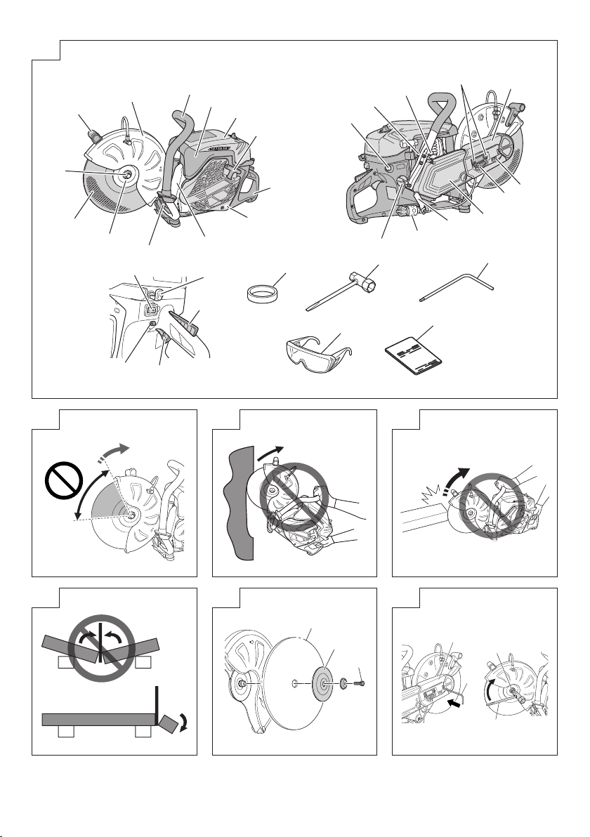
WHAT IS WHAT? (Fig. 1)
A: Stop switch: Device for allowing the engine to be started
or stopped.
B: Throttle lever: Device activated by the operatorʼs fi nger,
for controlling the engine speed.
C: Throttle lever lockout: Device that prevents the
accidental operation of the throttle lever until manually
released.
D: Throttle lock: Device for setting the throttle in partially
open position to aid starting.
E: Fuel tank cap: For closing the fuel tank.
F: Starter knob: Pull handle to start the engine.
G: Front handle: Support handle located at or towards the
front of the engine housing.
H: Rear handle: Support handle located at or towards the
rear of the engine housing.
I: Choke lever: Device for enriching the fuel/air mixture in
the carburetor, to aid starting.
J: Priming pump: Device for supplying extra fuel, to aid
starting.
K: Cleaner box (B): Cover for pre-fi lter
L: Cleaner box (A): Cover for paper-fi lter and carburetor.
M: Clutch cover: Device between the engine and the cutting
equipment designed to prevent unintentional contact
with the transmission.
N: Arm cover: Device between the engine and the cutting
equipment designed to prevent unintentional contact
with the transmission.
O: Wheel guard: Cover which is intended to protect the
operator from wheel contact, and also directs debris
away from the operator.
P: Nut: Secures the wheel guard to engine.
7
Page 8

English
Q: Anti-vibration spring: Reduce the transmission of
vibrations to the operator’s hands.
R: Handle(W): Handle for rotating the wheel guard.
S: Decompression valve: Device for reducing the
compression pressure of engine to aid starting.
T: Tensioner bolt: Device to increase and release belt
tension.
U: Tension nut: Mark for indicating the state of tension of
the belt.
V: Cut-off wheel: Bonded abrasive with reinforced resinoid
wheel for cutting, with blotter.
W: Coupler: Device for attaching the hose
X: Valve: Device for adjusting water fl ow rate.
Y: Muffl er: Reduces engine exhaust noise and directs the
exhaust gases.
Z: Wheel washer: Flange provided to clamp and drive the
cut-off wheel.
a: Bolt: Secures the cut-off wheel
b: Adapter collar: Spindle attachment for using arbor hole
25.4mm cut-off wheels.
c: Combi box spanner: Maintenance tool for removing or
installing a spark plug
d: Hex. wrench: Maintenance tool for removing cover and
tensioning the belt.
e: Protective glasses: Eye protection.
f: Handling instructions: Included with unit. Read before
operation and keep for future reference to learn proper,
safe techniques.
WARNINGS AND SAFETY
INSTRUCTIONS
Operator safety
○ Always wear a proper face shield or protective glasses.
○ Gloves should always be worn when operating this
machine and also when touching the cut-off wheel.
○ When using this machine, always wear proper protective
attire such as jacket, trousers, helmet, boots with steel
toe-caps and non-slip soles, and eye, ear, leg protection
equipment whenever you use this machine.
Do not wear loose clothing, jewelry, short pants and/or
sandals, or go barefoot.
○ Never let a child or inexperienced person operate the
machine.
A fi rst-time operator should obtain practical instruction
before using the machine.
○ When you wear hearing protection, pay attention to your
surroundings. Be aware of any bystanders who may be
signaling a problem.
○ Cutting operations can expose you to respiratory
hazards such as silica and other harmful dust particles.
Please wear a protective mask when operating this
machine.
○ Keep handles free of oil and fuel.
○ Keep hands away from cutting equipment.
○ Do not grab or hold the machine by the cutting
equipment.
○ Do not smoke or allow smoking near fuel or the machine,
or while using the machine.
○ When the unit is shut off , make sure the cutting
attachment has stopped before setting down the unit.
○ When operation is prolonged, take a break periodically
so that you may avoid possible Hand-Arm Vibration
Syndrome (HAVS) which is caused by vibration.
○ National regulation can restrict the use of machine.
And the operator must obey the local regulations of
working area.
WARNING
○ The machine produces exhaust fumes, which include
hydrocarbons and benzene. When using this machine,
suffi cient ventilation is needed, not only if used indoors
but also when working in trenches, hollows or other
confi ned locations. Breathing exhaust fumes can be
fatal.
○ Do not operate this machine when you are tired, ill or
under the infl uence of alcohol, drugs or medication.
○ Antivibration systems do not guarantee that you will not
sustain Hand-Arm Vibration Syndrome or carpal tunnel
syndrome.
Therefore, continual end regular users should monitor
closely the condition of their hands and fi ngers. If any
of the above symptoms appear, seek medical advice
immediately.
○ Long or continuous exposure to high noise levels may
cause permanent hearing impairment. Always wear
approved hearing protection when operating a machine.
○ If you are using any medical electric/electronic devices
such as a pacemaker, consult your physician as well as
the device manufacturer prior to operating any power
equipment.
Unit / machine safety
○ Inspect the entire machine for any damage before each
use. Check for fuel leaks and make sure all fasteners are
in place and securely tightened.
○ Keep others away when making carburetor adjustments.
○ Use only accessories as recommended for this machine
by the manufacturer.
○ Select and mount the correct cut-off wheel for the type of
work to be carried out.
○ All items, other than the items listed in the operator’s/
owner’s manual, should be performed by HiKOKI
Authorized Service Centers. (For example, if improper
tools are used to remove the fl ywheel or if an improper
tool is used to hold the fl ywheel in order to remove the
clutch, structural damage to the fl ywheel could occur
and could subsequently cause the fl ywheel to burst.)
WARNING
○ Never modify the machine in any way. Do not use your
machine for any job except that for which it is intended.
○ Never use wheels that are rated for speeds lower than
the maximum spindle speed indicated on the machine.
A wheel running faster than its rated speed can break
and fl y apart.
○ The arbor size of wheels and fl anges must properly fi t
the spindle of the machine.
Wheels and fl anges with arbor holes that do not match
the mounting hardware of the machine will run off -
balance, vibrate excessively and may cause loss of
control.
○ It is important to use only cut-off wheels designed for use
on hand-held cut-off machines. It is dangerous to use a
cut-off wheel that is not intended for a hand-held cut-off
machine.
Fuel safety
○ Mix and pour fuel outdoors and where there are no
sparks or fl ames.
○ Use a container approved for fuel.
○ Wipe off all fuel spills and allow any remaining fuel to
evaporate before starting engine.
○ Move at least 3 m away from fueling site before starting
engine.
○ Stop engine and let it cool for a few minutes before
opening fuel tank cap.
○ Store the machine and fuel in area where fuel vapors
cannot reach sparks or open fl ames from water heaters,
electric motors or switches, furnaces, etc.
8
Page 9

WARNING
Fuel is highly fl ammable and its fumes should not be
inhaled. Be particularly careful when handling the
machine as the sparks produced when cutting metal can
easily ignite any fuel spillage.
Cutting safety
○ Keep bystanders at a safe distance, away from the
work area. Anyone entering the work area must wear
personal protective equipment. Flying fragments from
the workpiece or the cut-off wheel may cause injury.
Children, other unauthorized persons and animals must
remain well away from the work area.
○ Hold the machine fi rmly with the right hand on the rear
handle and the left hand on the front handle.
○ Keep fi rm footing and balance. Do not over-reach.
○ Keep all parts of your body away from the muffl er and
cutting attachment when the engine is running.
○ Make sure to check the work area for any hidden
hazards such as water or gas pipes, electrical cables
and fl ammable substances.
○ Never place the machine on the ground when running.
○ Always ensure that the engine is shut off and any cutting
attachments have completely stopped before clearing
debris from the cutting attachment.
○ Always carry a fi rst-aid kit when operating any power
equipment.
○ The muffl er gets very hot during and after use. This also
applies during idling.
Be aware of the fi re hazard, especially when working
near fl ammable substances and/or vapours.
WARNING
○ Exhaust gases from the engine are hot and may contain
sparks which can cause a fi re.
Also, sparks are generated when cutting metal with this
machine.
Never use the machine where fl ammable substances
and gases are present.
○ Sparks generated from cutting operations can cause
fi res. Always have adequate fi re extinguishing equipment
available.
○ When relocating to a new work area, be sure to shut off
the machine and ensure that all cutting attachments are
stopped.
○ Always ensure that the engine is shut off and any cutting
attachments have completely stopped before moving.
Gyroscopic forces occur when moving while the engine
is operating and the cut-off wheel is rotating. This may
cause you to lose control of the machine.
○ Never cut materials that consist of asbestos.
○ Never leave the engine running while unattended
(e.g. on the ground).
Kickback and related warnings
Kickback is a sudden reaction to a pinched or snagged
rotating wheel. Pinching or snagging causes sudden stalling
of the rotating wheel which in turn causes the machine to
be forced in the direction opposite of the wheel's rotation at
the point of the binding. For example, if an abrasive wheel is
snagged or pinched by the workpiece, the edge of the wheel
that is entering into the pinch point can dig into the surface of
the material causing the wheel to climb out or kick out. The
wheel may either jump toward or away from the operator,
depending on the direction of the wheel's movement at the
point of pinching. Abrasive wheels may also break under
these conditions.
Either of these reactions may cause you to lose control of the
machine which could result in serious personal injury.
Kickback is the result of cut-off machine misuse and/or
incorrect operating procedures or conditions that can be
avoided by taking proper precautions as given below.
English
○ Kickback occurs when the upper angle of the cut-off
wheel is used or touches an object when the cut-off
wheel is running. Pay special attention not to touch the
upper angle of the cut-off wheel to any object. (Fig. 2,
Fig. 3)
○ Use special care when working corners, sharp edges
etc. Avoid bouncing and snagging the cut-off wheel.
Corners, sharp edges or bouncing have a tendency to
snag the rotating wheel and cause loss of control or
kickback. (Fig. 4)
○ Do not use cut-off wheels other than those approved or
recommended by the manufacturer. Never use blades
designed for cutting wood. Failure to comply could result
in personal accidents or injury.
○ Do not jam the wheel or apply excessive pressure. Do
not attempt to make an excessive depth of cut.
Overstressing the wheel increases the loading and
susceptibility to twisting or binding of the wheel in the cut
and the possibility of kickback or wheel breakage.
○ If the wheel binds or a cut is interrupted for any reason,
stop the engine and hold the machine motionless until
the wheel comes to a complete stop. Never attempt
to remove the wheel from the cut while the wheel is in
motion otherwise kickback may occur. Investigate and
take corrective action to eliminate the cause of wheel
binding.
○ Do not restart the cutting operation with the wheel in the
workpiece. After allowing the wheel to reach full speed,
carefully re-enter the cut. The wheel may bind, walk up or
kickback if the power tool is restarted in the workpiece.
○ Provide supports for panels or any oversized workpiece
to minimize risk of wheel pinching and kickback.
Large workpieces tend to sag under their own weight.
Supports must be placed under the workpiece so that
the cutting surface to open. (Fig. 5)
Maintenance safety
○ Maintain the machine according to recommended
procedures.
○ Disconnect the spark plug before performing
maintenance except for carburetor adjustments.
○ Keep others away when making carburetor adjustments.
○ Use only genuine HiKOKI replacement parts as
recommended by the manufacturer.
CAUTION
Do not disassemble the recoil starter. There is a
possibility of personal injury with recoil spring.
WARNING
Improper maintenance could result in serious engine
damage or in serious personal injury.
Transport and storage
○ Carry the machine by hand with the engine stopped and
the muffl er away from your body.
○ Allow the engine to cool, empty the fuel tank and
carburetor, and secure the machine before storing or
transporting.
○ Store machine out of the reach of children.
○ Clean and maintain the machine carefully and store it in
a dry place.
○ Make sure stop switch is off when transporting or storing.
○ Do not store the cut-off wheels in a wet or frost condition.
Pay special attention about the abrasive wheel.
There is a risk of bursting to using the abrasive wheel
wetted.
If situations occur which are not covered in this manual, take
care and use common sense. Contact HiKOKI Authorized
Service Centers if you need assistance.
9
Page 10

English
SPECIFICATIONS
3
Engine displacement (cm
) 75.0
Spark Plug NGK BPMR-7A
Max. engine power by ISO 7293 (kW) 3.9
Model CM75EAP CM75EBP
-1
Rated engine speed by ISO 7293 (min
-1
Max. engine speed (min
Idle engine speed (min
) 9800
-1
) 2500
) 9200
Fuel Tank Capacity (L) 1.1
Dry weight (kg)
Without fuel, wheel and accessories
10.4 10.6
Wheel type Type 41
Outer diameter (mm) 305 (12") 355 (14")
Abrasive wheel
Arbor hole diameter (mm) 20 (25.4 with Adapter collar)
-1
Max. speed (min
) 5100 or more
Max. Thickness (mm) 3.5 4.0
Outer diameter (mm) 305 (12") 355 (14")
Diamond wheel
Arbor hole diameter (mm) 20 (25.4 with Adapter collar)
-1
Max. speed (min
) 5100 or more
Max. Thickness (mm) 3.5 4.0
Minimum fl ange outside diameter (mm) 101.7
Wheel-fastener tightening torque (N·m) 20
Spindle diameter (mm) 20 (25.4 with Adapter collar)
-1
Spindle max. speed (min
Sound pressure level LpA
Sound power level LwA*2 (dB(A)) by ISO 19432
Vibration level (m/s
NOTE
Noise level/vibration levels are calculated as the time-
weighted energy total for noise / vibration levels under
various working conditions with the following time
distribution:
*1:1/7 idle, 6/7 full load.
*2: Full load.
All data subject to change without notice.
ASSEMBLY PROCEDURES
Assembly of cut-off wheel
1. Place the wheel (1) between the two fl anges (2), and
tighten the bolt (3) by hand. (Fig. 6)
2.
Insert the hex. wrench (4) into the hole of arm cover (5)
and lock the spindle in place while tightening the bolt (3)
securely using the combi box spanner (6). (Fig. 7)
3. Make sure the rotation direction of the diamond wheel
conforms to the direction indicated on the clutch cover
and install the diamond wheel. (Fig. 8)
NOTE
○
When using a wheel with an arbor hole of 25.4mm, securely
attach the adapter collar (7) to the spindle. (Fig. 9)
○ Select and mount the correct cut-off wheel for the type of
work to be carried out.
) 4200
*1
(dB(A)) by ISO 19432
Measured / Uncertainty 99.5 / 3.0
Measured / Uncertainty 115 / 3.0
2
) by ISO 19432
Front handle
*1
/ Rear handle
Uncertainty
*1
2.2 / 2.7
1.0
Abrasive wheels Diamond wheels
Plastic
(Special wheel) —
Masonry
Metal (Special wheels)
Cast iron
WARNING
○ Do not use damaged wheels. Before each use, inspect
the wheels for chips, cracks, distortion of shape or
imbalance and reject any such wheel.
○ When you use the abrasive cut-off wheel check the
expiration year marked (8) on the wheel before attaching.
(Fig. 10)
There is a risk of bursting when using a wheel that it past
its expiration year.
○ Before tightening the bolt, check that the direction of the
two fl anges is correct. Also check that the fl anges are
securely installed in the fl ats of the spindle.
○ The correct tightening torque is 20 N·m. Do not tighten
more than 20 N·m.
○ Check the wheel by running it for 1 minutes at full throttle
before applying it to a workpiece.
2.4 / 2.9
1.0
(Special wheels)
10
Page 11

Adjustment of belt
1. Loosen the nut (9) with the combi box spanner (6) so that
the arm cover can (10) move. (Fig. 11)
2. Use the hex. wrench (4) to rotate the tensioner bolt (11)
so that the position of the tension nut (12) matches with
the marking (13) on the arm cover (10). (Fig. 12, Fig. 13)
3. Tighten the nut again.
NOTE
Suffi cient power is not transmitted to the wheel when the
belt is loose. Appropriately adjust the belt as necessary.
Adjustment of wheel guard
1. Wheel guard (14) can be moved by hand without using
a tool. To adjust the wheel guard (14), use handle(W)
(15), or press the end of wheel guard (14) against the
workpiece. (Fig. 14)
Make sure to adjust the wheel guard (14) to shield you
from any fl ying debris. (Fig. 15)
Wet cutting with water
This machine can be set up for wet cutting which can
suppress dust emission during cutting.
1. Remove coupler (16) by pulling the coupler from the
machine. (Fig. 16)
2. Remove the ring (17) from the coupler, slide the ring over
the hose and insert the hose to the coupler. (Fig. 17)
3. Re-tighten the ring to the coupler securely.
4. Reattach the coupler to the machine until it locks into
position.
5. Running water into the hose, turn the lever (18) of valve
(19). (Fig. 18) This will supply to the cut-off wheel.
Warning
The cut-off wheel that is included with this machine is an
abrasive cut-off wheel for concrete, stone, or masonry.
When cutting with water supplied to this cut-off wheel,
use the wheel up on the same day. There is a risk of
bursting when using the abrasive wheel wetted in this
manner on the following day.
For other cut-off wheels, follow the instructions provided
with those cut-off wheels.
Mounting the tools to the machine (Fig. 19)
This machine is designed to store the combi box spanner (6)
and hex. wrench (4).
OPERATING PROCEDURES
Fuel
WARNING
○ The machine is equipped with a two-stroke engine.
Always run the engine on fuel, which is mixed with oil.
Provide good ventilation, when fueling or handling fuel.
○ Fuel is highly fl ammable and it is possible to get seriously
injured when inhaling or spilling on your body.
Always pay attention when handling fuel. Always have
good ventilation when handling fuel.
Fuel (Fig. 20)
○ Always use branded 89 octane unleaded gasoline.
○ Use genuine two-cycle oil or use a mix between 25:1 to
50:1, please consult about the oil mixture ratio to HiKOKI
Authorized Service Centers.
○ If genuine oil is not available, use an anti-oxidant added
quality oil expressly labeled for air-cooled 2-cycle engine
use (JASO FC GRADE OIL or ISO EGC GRADE). Do not
use BIA or TCW (2-stroke water-cooling type) mixed oil.
○ Never use multi-grade oil (10 W/30) or waste oil.
○ Never mix fuel and oil in machine’s fuel tank. Always mix
fuel and oil in a separate clean container.
Fuel mixing method
Always start by fi lling half the amount of gasoline, which is to
be used into container.
English
Then add the whole amount of oil. Mix (shake) the fuel
mixture. Add the remaining amount of gasoline.
Mix (shake) the fuel-mix thoroughly before fi lling the fuel tank.
Mixing amount of two-cycle oil and gasoline
Gasoline (Liter)
0.5 10 ——— 20
1 20 ——— 40
2 40 ——— 80
4 80 ——— 160
Fueling (Fig. 21)
Before fueling, clean fuel tank cap (20) area carefully to
ensure that no dirt falls into the tank. Make sure that the fuel
is well mixed by shaking the container before adding fuel.
WARNING
○ Always shut off the engine and let it cool for a few
minutes before refueling.
Do not smoke or bring fl ames or sparks near the fuel.
○ Slowly open the fuel tank cap (20), when fi lling up with
fuel, so that possible overpressure disappears.
○ Tighten the fuel tank cap carefully, after fueling.
○ Always move the unit at least 3 m from the fueling area
before starting.
○ Always wash any spilled fuel from clothing immediately
with soap.
○ Be sure to check any fuel leaking after refueling.
○ Before fueling, in order to remove static electricity from
the main body, the fuel container and the operator,
please touch the ground that is slightly damp.
Starting the cold engine (Fig. 22-27)
CAUTION
Before starting, make sure that the cut-off wheel does
not touch anything.
1. Set stop switch (21) to ON position. (Fig. 22)
2. Pull choke lever (22) fully to set it in the START position.
(Fig. 23)
3. Push the priming pump (23) approximately ten times so
that fuel fl ows into carburetor. (Fig. 24)
4. Fully pull the throttle lever (24) while pressing the throttle
lever lockout (25). Then press the throttle lock (27).
This will automatically lock to half throttle, to aid in
starting the engine. (Fig. 22)
5. Push the decompression valve (26). The valve will
automatically return to the original position once the
engine has started. (Fig. 25)
6. Holding the tool in position with the left hand on the front
handle (29) and the right foot pressing down on the rear
handle (30), rapidly pull the starter knob (28). (Fig. 26)
7. When you hear fi rst ignition, push the choke lever (22)
fully to set it in the run position. (Fig. 27)
8. Push decompression valve (26) again.
9. Pull starter knob (28) rapidly again in the aforementioned
manner.
10. As soon as the engine starts, pull throttle lever (24)
full once with throttle lever lockout (25) pressed and
immediately release throttle lock (27). Then half throttle
is disengaged.
11. Allow the engine to warm up for about 2 to 3 minutes
before cutting.
NOTE
To avoid reducing engine life, do not run the engine at
high speeds without any load over a long period of time.
Starting the warm engine
Use only 1, 5, and 6 of the starting procedure for a cold
engine.
If the engine does not start, use the same starting procedure
as for a cold engine.
11
Two-cycle oil (ml)
Ratio 50:1 Ratio 25:1
Page 12

English
Stopping (Fig. 28)
Decrease engine speed, and push stop switch (21) to stop
position.
WARNING
Do not put the machine where there are fl ammable
materials such as dried grass, since the muffl er is still
hot after the engine has stopped.
Basic cutting techniques
1. Adjust the wheel guard to shield you from fl ying debris.
2. Cut a straight shallow line (31) to the range to be cut.
(
Fig. 29
3. Cut straight along the line to the required depth.
○ Do not overreach or cut above shoulder height.
○
○
○
NOTE
○ When cutting, move the machine back and forward along
If you cut the same position in long time, the cut-off wheel
○ Always cut at full speed at all times with pressing lightly.
○ Do not cut a deep groove at one time. To make deep
)
WARNING
Operator and bystanders must not stand in the line of
rotation of the cut-off wheel. Doing so may result in serious
injury or death should the wheel burst.
Never apply lateral pressure (side force) to the cut-off
wheel during cutting. Doing so will damage the cut-off
wheel.
Do not cut in a curved line.
the line in order to be not overheat the cut-off wheel.
may get hot and be weakened.
This is the way to get best effi cient for cutting.
groove, cut several times a shallow groove.
MAINTENANCE
Carburetor adjustment
In the carburetor, fuel is mixed with air. When the engine is
test run at the factory, the carburetor is adjusted. A further
adjustment may be required, according to climate and
altitude. The carburetor has one adjustment possibility:
T = Idle speed adjustment screw.
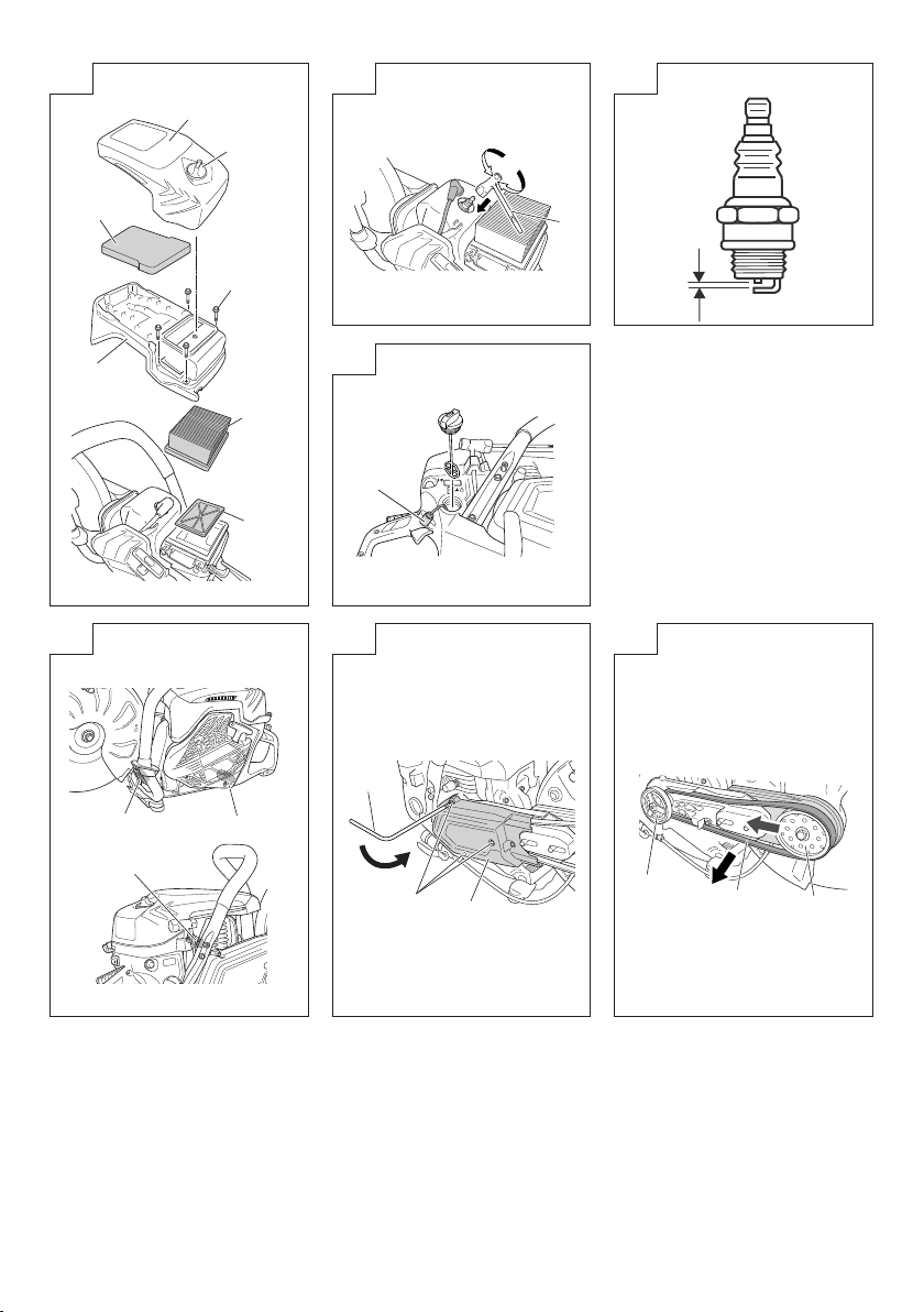
Idle speed adjustment (T) (Fig. 30)
Check that the pre-fi lter and paper fi lter are clean. When the
idle speed is correct, the cutting attachment will not rotate.
If adjustment is required, close (clockwise) the T-screw, with
the engine running, until the cutting attachment starts to
rotate. Open (counter-clockwise) the screw until the cutting
attachment stops. You have reached the correct idle speed
when the engine runs smoothly in all positions well below the
rpm when the cutting attachment starts to rotate.
If the cutting attachment still rotates after idle speed
adjustment, contact HiKOKI Authorized Service Centers.
WARNING
When the engine is idling, the cutting attachment must
not rotate under any circumstances.
NOTE
○ Please use combi box spanner for adjusting the T-screw.
○ Do not touch the High speed adjustment (H) and the
Low speed adjustment (L) screws on the carburetor.
Those are only for HiKOKI Authorized Service Centers.
If you rotate them, it will cause a serious damage to the
machine.
Air fi lter (Fig. 31)
If the engine power seems to have decreased, it is likely
because the air fi lter needs to be cleaned.
1. Before cleaning the air fi lter, pull the choke lever (22) to
prevent dust from entering into the engine.
2. Open cleaner box (B) (32) by loosening cleaner knob
(33) to expose the pre-fi lter (sponge form) (34) inside the
cleaner box (B) (32).
12
3. Clean the pre-fi lter by tapping or blowing it gently. If the
pre-fi lter is still dirty, rinse it in warm soap suds.
If the inside of cleaner box (B) (32) that is closed off by the
pre-fi lter is dirty with dust, clean the paper-fi lter (35) in the
following manner.
4. In order to take out of paper-fi lter (35) and nylon-fi lter
(36), open the cleaner box (A) (37) by loosening the M5
set bolt (38).
5. Clean the nylon-fi lter by tapping or blowing it gently. If
the nylon-fi lter is still dirty, rinse it in warm soap suds.
6. Clean the paper-fi lter by tapping. If you use compressed
air to blow out the dust, apply the air gently from inside.
7. Reassemble the parts to their original positions by
following the aforementioned steps in reverse.
NOTE
○ When you remove paper-fi lter and nylon-fi lter, please
take care so that dust does not get inside the engine.
○ After rinsing in warm soap suds. Check to make sure that
the fi lter is dry before reassembly. An air fi lter that has
been used for some time cannot be cleaned completely.
Therefore, it must regularly be replaced with a new one.
A damaged fi lter must always be replaced.
Spark plug (Fig. 31, 32, 33)
1. Remove cleaner box (B) (32) and cleaner box (A) (37).
(Fig. 31)
2. Remove the spark plug by turning it counterclockwise
with the combi box spanner. (Fig. 32)
3. Clean the spark plug if it is dirty. Check the electrode
gap. The correct gap is 0.6 mm. (Fig. 33)
NOTE
○ When you remove the spark plug, please take care so
that dust does not get inside the engine.
○ The spark plug should be replaced after about 100
operation hours or earlier if the electrodes are badly
eroded.
Fuel fi lter (Fig. 34)
Remove the fuel fi lter (39) from the fuel tank and thoroughly
wash it in solvent. After that, push the fuel fi
completely.
NOTE
If the fuel fi lter (39) is hard due to dust and dirt, it must be
replaced.
Anti-vibration systems (Fig. 35)
Check the springs (40) for any loosening or damage. If you
fi nd any failure in those parts, please contact a HiKOKI
Authorized Service Center.
Replacing of belt
1. Remove nut (9) using the combi box spanner (6)
and loosen the tensioner bolt (11) by rotating it
counterclockwise with the hex. wrench (4). Then,
remove the arm cover (10). (Fig. 11, 12)
2. Loosen the three bolts (41) on the clutch cover (42) and
remove clutch cover (42). (Fig. 36)
3. Remove the belt (43) and set a new one in the grooves of
the pulleys (44)(45) securely. (Fig. 37, 38)
4. Before assembling, turn the tensioner bolt (11) and
adjust the length protrusion of the tensioner bolt (11)
from the arm cover (10) to 0 mm. (Fig. 39)
5. Assemble clutch cover and arm cover by following the
aforementioned steps in reverse.
6. Readjust the tension of the belt. Please refer to
“Adjustment of belt”.
lter into the tank
Page 13

Maintenance schedule
Daily maintenance
○ Clean the exterior of the machine.
○
Check that the nut on the arm cover is suffi ciently tightened.
○
Check that the bolts for the cut-off wheel are suffi ciently
tightened.
○
Check that the cut-off wheel does not rotate when the
engine is idling
○ Clean the air fi lter.
Weekly maintenance
○ Check the recoil starter, especially rope.
○ Clean the exterior of the spark plug.
○ Remove the spark plug and check the electrode gap.
Adjust it to 0.6 mm or change the spark plug.
○
Check that the air intake at the recoil starter is not clogged.
TROUBLESHOOTING
Condition Probable Cause Remedy
No fuel or low fuel Supply fuel
Fuel is not in the carburetor
Old fuel Supply new fuel
Spark plug is wet
Engine does not start
Engine starts but immediately stalls
Abnormal vibration
Engine starts, but the cut-off wheel
does not rotate
Engine does not stop Electrical system failure
The fuel pipe is bent or detached
Carburetor failure
Spark plug failure Replace spark plug or correct the gap
Electrical system failure
No fuel or low fuel Supply fuel
Fuel is not in the carburetor
The choke is closed Push choke lever securely
Carburetor failure
Spark plug failure Replace spark plug or correct the gap
Clogged air fi lter Clean the air fi lter
Faulty mounting of the cut-off wheel
Deformation of the cut-off wheel Replace the cut-off wheel
Anti-vibration system failure
Belt is loose
Belt is too tight
Belt is out of pulleys Please refer to “Replacing of belt”
English
Monthly maintenance
○ Rinse the fuel tank with gasoline, and clean fuel fi lter.
○ Clean the exterior of the carburetor and the space
around it.
Quarterly maintenance
○ Clean the cooling fi ns on the cylinder.
○ Clean the fan and the space around it.
○ Clean the carbon of muffl er.
CAUTION
Cleaning of cylinder fi ns, fan and muffl er shall be done
by HiKOKI Authorized Service Centers.
Supply fuel and push priming pump a
few times.
1. Remove spark plug and dry it
2. Pull starter and dry the fuel inside
the engine
Consult a HiKOKI Authorized Service
Center
Consult a HiKOKI Authorized Service
Center
Consult a HiKOKI Authorized Service
Center
Supply fuel and push priming pump a
few times.
Consult a HiKOKI Authorized Service
Center
Please refer to “Assembly of cut-off
wheel”
Consult a HiKOKI Authorized Service
Center
Please refer to “Adjustment of belt”
Consult a HiKOKI Authorized Service
Center
13
Page 14

English
SPECIAL ACCESSORIES
Diamond wheel
HiKOKI off ers a diamond wheel for a variety of applications
which are listed below.
Diamond wheels (12") for CM75EAP
Type Category Outer Dia. (mm) Arbor hole (mm) Code No.
Universal 300 20
Diamond wheel
Diamond wheels (14") for CM75EBP
Type Category Outer Dia. (mm) Arbor hole (mm) Code No.
Diamond wheel
Water pressure tank (Fig. 40)
HiKOKI water pressure tank is a portable and manual
pressured tank. This tank allows wet cutting where
there is no immediately available water supply.
(Code No.: 712630)
Brick and asphalt 300 20
Concrete and hard
stone
Universal 350 20
Brick and asphalt 350 20
Concrete and hard
stone
300 20
350 20
773000
773004
773137
773018
773008
773012
773002
773006
773016
773020
773010
773014
REPLACEMENT PARTS
6699872 6699868 6699867 6699877
14
Page 15

Dedique especial atención a los apartados introducidos por
las siguientes palabras:
ADVERTENCIA
Indica un riesgo signifi cativo de que se produzcan daños
personales graves e incluso la muerte si no se siguen las
instrucciones.
PRECAUCIÓN
Indica la posibilidad de que se produzcan daños
personales o materiales si no se siguen las instrucciones.
NOTA
Indica información útil para el uso y funcionamiento
correctos de la máquina.
Español
Dimensiones del disco de corte
Mezcla de combustible y aceite
Ajuste del carburador: velocidad a ralentí
Ajuste del carburador: mezcla a baja velocidad
SIGNIFICADO DE LOS SÍMBOLOS
NOTA: Algunas unidades no están provistos de ellos.
Símbolos
ADVERTENCIA
A continuación se muestran los símbolos
utilizados para la máquina. Asegúrese de
comprender su signifi cado antes de utilizar el
dispositivo.
Cuchilla: Máquina de corte portátil
CM75EAP / CM75EBP
Es importante que lea, entienda totalmente
y respete las siguientes precauciones
y advertencias de seguridad. El uso
descuidado o incorrecto de la unidad podría
provocarle lesiones graves o fatales.
Lea, comprenda y siga todas las advertencias
y demás instrucciones de este manual y las
que se muestran en el aparato.
Cuando utilice esta unidad, use siempre
protecciones para los ojos, la cabeza, los
oídos y protecciones antipolvo
Estárter
Encendido / Arranque
Apagado / Parada
Parada de emergencia
Velocidad máxima del husillo de la máquina.
Advertencia: No utilice discos con una
capacidad de velocidad inferior a la velocidad
máxima indicada del husillo de la máquina.
¡Advertencia de incendios! Esta herramienta
genera chispas al cortar metal.
¡Advertencia! No utilice discos de corte
dañados.
Dirección de giro del disco de corte
Ajuste del carburador: mezcla a alta velocidad
Bomba de cebado
Nivel de potencia acústica garantizado
8
Válvula de descompresión
Advertencia de polvo y emisiones de gas
dañinos
¡Advertencia de retroceso
¡Advertencia! Nunca utilice cuchillas
diseñadas para cortar madera.
DESCRIPCIÓN DE LAS PARTES (Fig. 1)
A: Interruptor de parada: Dispositivo que permite arrancar y
detener el motor.
B: Palanca del acelerador: Dispositivo activado mediante el
dedo del operario para controlar la velocidad del motor.
C: Bloqueo de la palanca del acelerador: Dispositivo que
evita el funcionamiento accidental de la palanca del
acelerador hasta que se libera manualmente.
D: Bloqueo del acelerador: Dispositivo de confi guración
del acelerador en la posición parcialmente abierta para
ayudar al arranque.
E: Tapa del depósito de combustible: Para cerrar el
depósito de combustible.
F: Mando del arrancador: Tire del asidero para arrancar el
motor.
G: Asidero frontal: Asidero de apoyo situado en la parte
frontal de la carcasa del motor u orientado hacia ella.
H: Asidero trasero: Asidero de apoyo situado en la parte
trasera de la carcasa del motor u orientado hacia ella.
I: Palanca del estárter: Dispositivo para enriquecer la
mezcla de combustible/aire, para ayudar al arranque.
J: Bomba de cebado: Dispositivo para suministrar
combustible adicional para ayudar al arranque.
K: Caja del fi ltro (B): Cubierta del prefi ltro
L: Caja del fi ltro (A): Cubierta del fi ltro de papel y del
carburador.
M: Tapa del embrague: Dispositivo entre el motor y el
equipo de corte diseñado para evitar el contacto no
intencionado con la transmisión.
15
Page 16

Español
N: Cubierta del brazo: Dispositivo entre el motor y el
equipo de corte diseñado para evitar el contacto no
intencionado con la transmisión.
O: Protección del disco: Cubierta diseñada para proteger al
operario del contacto del disco y para alejar los residuos
del operario.
P: Tuerca: Fija la protección del disco al motor.
Q: Resorte antivibración: Reduce la transmisión de
vibraciones a las manos del operario.
R: Asidero (W): Asidero para girar la protección del disco.
S:
Válvula de descompresión: Dispositivo para reducir la
presión de compresión del motor para ayudar al arranque.
T: Perno tensor: Dispositivo para aumentar y liberar tensión
de la correa.
U: Tuerca de tensión: Marca para indicar el estado de la
tensión de la correa.
V: Disco de corte: Disco abrasivo adherido con resina
sintética reforzada para el corte con papel secante.
W: Acoplador: Dispositivo para instalar la manguera
X: Válvula: Dispositivo para ajustar la tasa del fl ujo de agua.
Y: Silenciador: Reduce el ruido de salida de escape del
motor y dirige los gases de escape.
Z: Arandela del disco: Brida suministrada para fi jar y dirigir
el disco de corte.
a: Perno: Fija el disco de corte
b: Anillo adaptador: Accesorio del husillo para el uso de
discos de corte de 25,4 mm de orifi cio de eje.
c:
Llave combinada de cubo: Herramienta de mantenimiento
para extraer o instalar una bujía
d: Llave hexagonal: Herramienta de mantenimiento para
extraer cubiertas y tensar la correa.
e: Gafas protectoras: Protección para los ojos.
f: Instrucciones de manejo: Incluidas con la unidad. Lea las
instrucciones para aprender a utilizar apropiadamente
y con seguridad la unidad, y guárdelas para futuras
referencias.
ADVERTENCIAS E INSTRUCCIONES
DE SEGURIDAD
Seguridad del usuario
○ Use siempre protección facial o gafas protectoras
adecuadas.
○ Al operar esta máquina y tocar el disco de corte, debe
usar siempre guantes.
○ Utilice siempre indumentaria protectora adecuada tal
como chaqueta, pantalones, casco, botas con puntera
de acero y suelas antideslizantes, así como equipo de
protección ocular, auditivo y para las piernas, cuando
utilice esta máquina.
No utilice prendas sueltas, joyas, pantalones cortos y/o
sandalias, y nunca trabaje descalzo.
○ No deje que niños o personas inexpertas utilicen esta
máquina.
El operario primerizo deberá obtener instrucciones
prácticas antes de usar la máquina.
○ Cuando use protección auditiva, preste atención a los
alrededores. Esté atento a personas que pudieran estar
avisándole de un problema.
○ Las operaciones de corte pueden exponerlo a peligros
respiratorios tales como sílice y otras partículas de
polvo perjudiciales. Al utilizar esta máquina, utilice una
máscara protectora.
○ Mantenga los asideros libres de aceite y combustible.
○ Mantenga las manos alejadas del mecanismo de corte.
○ No agarre ni sostenga la máquina por el mecanismo de
corte.
○ No fume ni deje fumar a otras personas en las
proximidades del combustible o de la máquina ni cuando
utilice la misma.
○ Cuando apague la unidad, asegúrese de que el
mecanismo de corte se ha detenido antes de apoyar la
unidad sobre el suelo.
○ Si utiliza este dispositivo durante un periodo de tiempo
prolongado, se recomienda descansar de vez en cuando
para evitar el posible Síndrome por vibración en manos y
brazos (HAVS), causado por las vibraciones.
○ Las normativas nacionales pueden restringir el uso de la
máquina.
El operario deberá respetar los reglamentos locales del
área de trabajo.
ADVERTENCIA
○ La máquina genera gases de escape, que incluyen
hidrocarburos y benceno. Al utilizar esta máquina,
necesitará la ventilación adecuada no solamente al
usarse en interiores, sino también al usarse en zanjas,
cavidades y otras ubicaciones confi nadas. La inhalación
de los humos de escape puede ser fatal.
○ No utilice esta máquina cuando esté cansado, enfermo o
bajo la infl uencia del alcohol, drogas o medicamentos.
○ Los sistemas antivibración no garantizan que no se
vaya a padecer del Síndrome por vibración en manos y
brazos o el síndrome del túnel carpiano.
Por lo tanto, aquellas personas que utilicen este dispositivo
de forma continua y regular deberán mantener vigilado en
todo momento el estado de sus manos y dedos. Si aparece
cualquiera de los síntomas citados, deberá solicitarse
inmediatamente atención médica.
○ La exposición prolongada o continua a niveles altos de
ruido puede causar discapacidad auditiva permanente.
Al utilizar una máquina que genere ruidos, utilice
siempre protección auditiva aprobada.
○ Si utiliza algún dispositivo médico eléctrico o electrónico
tal como marcapasos, consulte a su médico y al
fabricante del dispositivo antes de utilizar cualquier
equipo motorizado.
Seguridad de la máquina
○ Inspeccione toda la máquina en busca de daños
antes de cada uso. Compruebe que no haya fugas de
combustible y asegúrese de que todas las piezas se
encuentren en su sitio y estén correctamente apretadas.
○ No permita que se acerquen otras personas mientras
esté ajustando el carburador.
○ Utilice únicamente los accesorios para esta máquina
que hayan sido recomendados por el fabricante.
○ Seleccione y monte el disco de corte correcto para el
tipo de trabajo que se vaya a llevar a cabo.
○ Todos los artículos deberán efectuarse en los centros de
servicio autorizado de HiKOKI, a excepción de aquellos
indicados en el manual del propietario/operario. (Por
ejemplo, si se emplean herramientas incorrectas para
quitar el volante o si se utiliza una herramienta incorrecta
para sujetar el volante con el propósito de quitar el
embrague, podría ocasionar daños estructurales al
volante y provocar que se rompa).
ADVERTENCIA
○ Nunca intente modifi car la máquina de ninguna manera.
No utilice esta máquina para tareas distintas para las
que ha sido diseñada.
○ Nunca utilice discos con una capacidad de velocidad
inferior a la velocidad máxima indicada del husillo de la
máquina.
Un disco funcionando más rápido que su velocidad
nominal puede romperse y saltar en pedazos.
○ El diámetro del eje de los discos y bridas ha de encajar
correctamente en el husillo de la máquina.
Los discos y bridas que posean diámetros de eje que
no coincidan con el hardware de montaje de la máquina
se desequilibrarán, vibrarán excesivamente y podrían
causar una pérdida del control.
16
Page 17

○ Es importante utilizar únicamente discos de corte
diseñados para su uso en máquinas de corte portátiles.
Es peligroso utilizar un disco de corte no diseñado para
una máquina de corte portátil.
Seguridad del combustible
○ Mezcle y llene el combustible al aire libre, en lugares
donde no se produzcan chispas ni haya fuego.
○ Utilice un recipiente adecuado para el combustible.
○ Limpie los derrames de combustible y permita que
cualquier combustible restante se evapore antes de
arrancar el motor.
○ Antes de poner en marcha el motor, apártese como
mínimo 3 metros del lugar en el que se ha repostado el
combustible.
○ Detenga el motor y deje que se enfríe durante unos
minutos antes de abrir el tapón del depósito de
combustible.
○ Guarde la máquina y el combustible en un lugar donde
los vapores del combustible no puedan llegar a chispas
ni llamas de calentadores de agua, motores eléctricos,
interruptores, hornos, etc.
ADVERTENCIA
El combustible es altamente infl amable y sus vapores
no deben ser inhalados. Tenga especial cuidado al
manipular la máquina, ya que las chispas producidas
durante el proceso de corte de metal pueden infl amar
fácilmente cualquier derrame de combustible.
Seguridad durante el corte
○ Mantenga a los viandantes a una distancia segura del
área de trabajo. Cualquier persona que acceda a la zona
de trabajo deberá usar equipo protector personal. Los
fragmentos despedidos de las piezas de trabajo o del
disco de corte podrían causar lesiones.
Los niños, el resto de personal no autorizado y los
animales deberán permanecer alejados de la zona de
trabajo.
○ Agarre la máquina fi rmemente con la mano derecha
en el asidero trasero y la mano izquierda en el asidero
delantero.
○ Mantenga estable el cuerpo, con los pies bien apoyados
sobre el suelo. No estire demasiado el cuerpo.
○ Mantenga su cuerpo apartado del silenciador de escape
y del mecanismo de corte mientras esté en marcha el
motor.
○ Asegúrese de comprobar la zona de trabajo en busca
de peligros ocultos tales como tuberías de agua o gas,
cables eléctricos y sustancias infl amables.
○ Jamás coloque la máquina sobre el suelo cuando esté
en marcha.
○ Asegúrese siempre de que el motor esté apagado y de
que todos los accesorios de corte estén completamente
parados antes de limpiar los residuos del accesorio de
corte.
○ Cuando utilice cualquier equipo motorizado, lleve
siempre un botiquín de primeros auxilios consigo.
○ El silenciador alcanza temperaturas muy elevadas
durante y después de su uso. Esta situación también se
da durante su inactividad.
Tenga presente el riesgo de incendio, especialmente al
trabajar cerca de sustancias o vapores infl amables.
ADVERTENCIA
○ Los gases de escape del motor alcanzan temperaturas
muy elevadas y podrían contener chispas que podrían
provocar un incendio.
Además, al cortar metal con esta máquina se generan
chispas.
No utilice nunca la máquina en lugares en los que
existan substancias y gases infl amables.
○ Las chispas generadas por las operaciones de corte
podrían causar incendios. Tenga disponible en todo
momento un equipo de extinción de incendios adecuado.
Español
○ Cuando cambie para situarse en una nueva área de
trabajo, asegúrese de detener la máquina y de que
todos los accesorios de corte estén detenidos.
○ Asegúrese siempre de que el motor esté apagado y de
que todos los accesorios de corte estén completamente
parados antes de desplazarse.
Durante el transporte del motor mientras éste está
funcionando y el disco de corte está girando se producen
fuerzas giroscópicas. Esto podría provocar la pérdida de
control de la máquina.
○ Nunca corte materiales con amianto.
○ Nunca deje el motor en marcha desatendido
(por ejemplo, sobre el suelo).
Retroceso y advertencias relacionadas
Retroceso es una reacción repentina en un disco giratorio
enganchado o atrapado. El enganche o agarre causa el
estancamiento repentino del disco giratorio, el cual a su
vez, causa que la máquina salga disparada en dirección
opuesta al giro del disco en el punto de unión. Por ejemplo,
si un disco abrasivo queda atrapado o atascado a causa
de una pieza de trabajo, el borde del disco que pasa por el
punto de agarre puede penetrar en la superfi cie del material,
causando que el disco se monte o retroceda. El disco podría
entonces salir disparado hacia el operario o alejarse del
mismo, en función de la dirección del movimiento del disco
en el momento del atasco. Los discos abrasivos podrían,
igualmente, romperse en estas condiciones.
Cualquiera de estas reacciones podría hacer perder el
control de la máquina, pudiendo causar serias lesiones
personales.
Retroceso es el resultado un uso incorrecto de la máquina
de corte y/o los procedimientos de operación o condiciones
incorrectos que puede evitarse tomando las precauciones
necesarias, tal y como se indica a continuación.
○ El retroceso se produce cuando el ángulo superior del
disco de corte se usa o toca un objeto cuando el disco
de corte está en marcha. Preste especial atención para
no tocar el ángulo superior del disco de corte con ningún
objeto. (Fig. 2, Fig. 3)
○ Preste especial atención al trabajar en esquinas, bordes
afi lados, etc. Evite que el disco de corte rebote o se
quede atrapado.
Las esquinas, los bordes afi lados o el rebote tienden
a causar atascos en el disco giratorio y la pérdida de
control o el retroceso del mismo. (Fig. 4)
○ No utilice discos de corte distintos a los aprobados o
recomendados por el fabricante. Nunca utilice cuchillas
diseñadas para cortar madera. De lo contrario podría
causar accidentes personales o lesiones.
○ No atasque el disco ni aplique una presión excesiva. No
intente lograr una profundidad de corte excesiva.
Sobrecargar el disco aumenta la carga y la
susceptibilidad a giros o adhesiones del disco en el
corte, y la posibilidad de retroceso o rotura del disco.
○ Si el disco se atasca o se interrumpe un corte por cualquier
motivo, detenga el motor y mantenga la máquina inerte
hasta que el disco se detenga completamente. Nunca
intente extraer el disco del corte mientras el disco
está en movimiento, de lo contrario podría retroceder.
Averigüe el motivo y tome la acción correctiva necesaria
para eliminar la causa del atascamiento del disco.
○ No reinicie la operación de corte con el disco en la pieza
de trabajo. Una vez que el disco alcance la velocidad
máxima, vuelva a introducirlo en el corte con cuidado.
El disco podría atascarse, levantarse o retroceder si la
herramienta de alimentación es reiniciada en la pieza de
trabajo.
○ Proporcione soportes para paneles o cualquier pieza de
trabajo de gran tamaño para reducir el riesgo de que el
disco se atasque o retroceda.
17
Page 18

Español
Las piezas de trabajo grandes tienden a deslizarse por
su propio peso. Los soportes deben colocarse debajo de
la pieza de trabajo de forma que la superfi cie de corte se
abra. (Fig. 5)
Seguridad durante el mantenimiento
○ Realice el mantenimiento de la máquina siguiendo los
procedimientos recomendados.
○ Antes de iniciar el mantenimiento, desconecte la bujía,
excepto si hay que ajustar el carburador.
○ No permita que se acerquen otras personas mientras
esté ajustando el carburador.
○ Utilice únicamente repuestos y accesorios originales de
HiKOKI recomendados por el fabricante.
PRECAUCIÓN
No desmonte el arrancador de retroceso. El resorte
del arrancador puede ocasionarle lesiones personales
graves.
ADVERTENCIA
El mantenimiento incorrecto podría conducir a una
avería seria del motor o a heridas graves.
Transporte y almacenamiento
○ Transporte la máquina a mano con el motor detenido y el
silenciador alejado del cuerpo.
○ Antes de almacenar o transportar la máquina, espere
a que se haya enfriado el motor, vacíe el depósito de
combustible y el carburador y sujete bien la máquina.
○ Guarde la máquina fuera del alcance de niños.
○ Limpie y lleve a cabo el mantenimiento de la máquina
cuidadosamente, y guárdela en un lugar seco.
○ Asegúrese de que esté desconectado el interruptor de
parada al transportar o almacenar el aparato.
○ No guarde los discos de corte en lugares húmedos o
congelados. Preste especial atención al disco abrasivo.
Existe el riesgo de explosión si usa el disco abrasivo
humedecido.
Si se producen situaciones no previstas en este manual,
utilice el sentido común. Si necesita ayuda, póngase en
contacto con un centro de servicio autorizado HiKOKI.
ESPECIFICACIONES
3
Desplazamiento del motor (cm
) 75,0
Bujía NGK BPMR-7A
Potencia máx. del motor según ISO 7293 (kW) 3,9
Velocidad nominal del motor según ISO 7293 (min
-1
Velocidad máxima del motor (min
Velocidad de ralentí del motor (min
) 9800
-1
) 2500
Capacidad del depósito de combustible (L) 1,1
Peso en seco (kg)
Sin combustible, disco ni accesorios
Tipo de disco Tipo 41
Diámetro exterior (mm) 305 (12") 355 (14")
Disco abrasivo
Diámetro del orifi cio del eje (mm) 20 (25,4 con anillo adaptador)
Velocidad máx. (min
Grosor máximo (mm) 3,5 4,0
Diámetro exterior (mm) 305 (12") 355 (14")
Disco de diamante
Diámetro del orifi cio del eje (mm) 20 (25,4 con anillo adaptador)
Velocidad máx. (min
Grosor máximo (mm) 3,5 4,0
Diámetro exterior mínimo de la brida (mm) 101,7
Par de apriete del fi jador del disco (N·m) 20
Diámetro del husillo (mm) 20 (25,4 con anillo adaptador)
-1
Velocidad máx. del husillo (min
Nivel de presión acústica LpA
Nivel de potencia acústica LwA
Nivel de vibración (m/s
NOTA
Los niveles de ruido / vibración se calculan como la
energía ponderada en tiempo total para los niveles de
ruido/vibración en varias condiciones de trabajo con la
distribución de tiempo siguiente:
Medición / Incertidumbre
Medición / Incertidumbre
Asidero delantero
) 4200
*1
(dB(A)) según ISO 19432
*2
(dB(A)) según ISO 19432
2
) según ISO 19432
*1
/ Asidero trasero
Modelo CM75EAP CM75EBP
-1
) 9200
10,4 10,6
-1
) 5100 o más
-1
) 5100 o más
99,5 / 3,0
115 / 3,0
Incertidumbre
*1
2,2 / 2,7
1,0
*1: 1/7 ralentí, 6/7 carga completa.
*2: Carga completa.
Todos los datos están sujetos a cambios sin previo aviso.
18
2,4 / 2,9
1,0
Page 19

PROCEDIMIENTOS DE MONTAJE
Conjunto del disco de corte
1. Coloque el disco (1) entre las dos bridas (2), y apriete
manualmente el perno (3). (Fig. 6)
2. Introduzca la llave hexagonal (4) en el orifi cio de la
cubierta del brazo (5) y bloquee el husillo en su lugar
mientras aprieta el perno (3) fi rmemente utilizando la
llave combinada de tubo (6). (Fig. 7)
3. Asegúrese de que la dirección de rotación de la rueda de
diamante se encuentra en conformidad con la dirección
indicada en la cubierta del embrague e instale la rueda
de diamante. (Fig. 8)
NOTA
○ Al usar un disco con un orifi cio del eje de 25,4 mm,
coloque fi rmemente el anillo adaptador (7) en el husillo.
(Fig. 9)
○ Seleccione y monte el disco de corte correcto para el
tipo de trabajo que se vaya a llevar a cabo.
Discos abrasivos Discos de
Plástico (disco especial) —
Mampostería
Metal
Hierro fundido
ADVERTENCIA
○ No use discos dañados. Antes de cada uso, inspeccione
los discos en busca de virutas, grietas, pérdida de la
forma o desequilibrio y rechace tal tipo de discos.
○ Al usar el disco de corte abrasivo, compruebe la fecha
(8) de expiración indicada en el disco antes de instalarlo.
(Fig. 10)
Cuando se usa un disco cuyo año de caducidad ha
terminado, pueden producirse riesgos de explosión.
○ Antes de apretar el perno, compruebe que la dirección
de las dos bridas sea correcta. Compruebe también que
las bridas están fi rmemente instaladas en las bases del
husillo.
○ El par de apriete correcto es 20 N·m. No apriete por
encima de 20 N·m.
○ Compruebe el disco dejándolo en marcha durante 1
minuto a máxima aceleración antes de aplicarlo a una
pieza de trabajo.
Ajuste de la correa
1. Afl oje la tuerca (9) con la llave combinada de cubo (6)
de modo que la cubierta del brazo (10) pueda moverse.
(Fig. 11)
2. Utilice la llave hexagonal (4) para girar el perno tensor
(11) de modo que la posición de la tuerca de tensión (12)
coincida con la marca (13) de la cubierta del brazo (10).
(Fig. 12, Fig. 13)
3. Apriete la tuerca de nuevo.
NOTA
Si la correa está fl oja, no transmitirá sufi ciente energía al
disco. Debe ajustar adecuadamente la correa según sea
necesario.
Ajuste de la protección del disco
1. La protección del disco (14) puede extraerse
manualmente sin usar herramientas. Para ajustar la
protección del disco (14), use el asidero (W) (15) o
presione el extremo de la protección del disco (14)
contra la pieza de trabajo. (Fig. 14)
Asegúrese de ajustar la protección del disco (14) para
protegerse de cualquier resto que salga despedido. (Fig.
15)
diamante
(discos especiales)
(discos especiales)
Español
Corte en mojado con agua
Esta máquina se puede confi gurar para el corte en mojado,
lo cual puede suprimir la emisión de polvo durante el corte.
1. Extraiga el acoplador (16) tirando del acoplador de la
máquina. (
2.
Extraiga el aro (17) del acoplador, deslice el aro sobre
la manguera e introduzca la manguera en el acoplador.
(Fig. 17)
3. Vuelva a apretar el aro en el acoplador fi rmemente.
4. Vuelva a instalar el acoplador en la máquina hasta que se
bloquee en su posición.
5.
Haciendo correr agua por la manguera, gire la palanca
(18) de la válvula (19). (Fig. 18) Esto suministrará al
disco de corte.
Advertencia
El disco de corte incluido en esta máquina es un disco de
corte abrasivo para hormigón, piedra o mampostería.
Al cortar usando de agua suministrada a este disco de
corte, desgaste el disco ese mismo día. Existe el riesgo
de explosión cuando usa el disco abrasivo humedecido de
esta manera al día siguiente.
Para el resto de discos de corte, siga las instrucciones
proporcionadas con los mismos.
Montaje de las herramientas en la máquina (Fig. 19)
Esta máquina está diseñada para almacenar la llave
combinada de cubo (6) y la llave hexagonal (4).
Fig. 16
)
PROCEDIMIENTOS DE
FUNCIONAMIENTO
Combustible
ADVERTENCIA
○ La máquina está equipada con un motor de dos tiempos.
El motor debe funcionar siempre con combustible
mezclado con aceite. Asegúrese de que existe una
buena ventilación en los lugares de manipulación o
repostaje de combustible.
○
El combustible contiene sustancias altamente infl amables,
por lo que existe la posibilidad de sufrir lesiones graves por
inhalación o por derrames sobre su cuerpo.
Preste siempre atención cuando manipule el combustible.
Cuando manipule el combustible, asegúrese de que haya
una buena ventilación en todo momento.
Combustible (Fig. 20)
○
Utilice siempre gasolina sin plomo de marca de 89 octanos.
○
Utilice aceite de dos tiempos genuino o utilice una mezcla
de 25:1 a 50:1. Consulte la proporción de la mezcla de
aceite a un centro de servicio autorizado HiKOKI.
○ Si no hay aceite genuino disponible, utilice un aceite
con antioxidante de calidad que esté etiquetado
expresamente para motores de dos tiempos refrigerados
por aire (JASO FC GRADE OIL o ISO EGC GRADEC).
No utilice aceite mezclado BIA o TCW (para motores de
2 tiempos refrigerados por agua).
○ No utilice nunca aceites multigrado (10 W/30) ni
residuales.
○ Nunca mezcle el combustible y el aceite en el depósito
de combustible de la máquina. Mezcle siempre el
combustible y el aceite en un recipiente limpio y
destinado a este fi n.
Método de mezcla de combustible
Comience siempre llenando la mitad del combustible que va
a utilizar en el contenedor.
Luego, agregue todo el aceite. Agite la mezcla de
combustible. Añada el resto de gasolina.
Antes de llenar el depósito de combustible, agite bien la mezcla.
19
Page 20

Español
Cantidad de mezcla de aceite de dos tiempos y gasolina
Gasolina (litros)
0,5 10 ——— 20
1 20 ——— 40
2 40 ——— 80
4 80 ——— 160
Repostaje (Fig. 21)
Antes de repostar, limpie cuidadosamente la zona de la
tapa del depósito de combustible (20) para asegurarse de
que no entra suciedad en el depósito. Asegúrese de que
el combustible está bien mezclado agitando el recipiente
antes de añadir combustible.
ADVERTENCIA
○ Antes de repostar el combustible, apague el motor y
deje que se enfríe durante unos minutos.
No fume ni acerque llamas o chispas cerca del combustible.
○ Al repostar combustible en el depósito, abra lentamente
la tapa del depósito de combustible (20) para drenar el
exceso de presión que pueda contener.
○ Después del repostaje, cierre y apriete bien la tapa del
depósito de combustible.
○ Antes de arrancar la máquina, debe alejarse un mínimo
de 3 m del área de repostaje.
○ Lave siempre inmediatamente con jabón cualquier
combustible vertido sobre la ropa.
○ Asegúrese de verifi car si existe alguna fuga de
combustible después del repostaje.
○ Antes de repostar, y con el fi n de descargar la
electricidad estática del cuerpo principal, del recipiente
y del operario, toque una superfi cie de suelo ligeramente
humedecida.
Arranque del motor en frío (Fig. 22-27)
PRECAUCIÓN
Antes de arrancar, asegúrese de que el disco de corte
no entre en contacto con nada.
1. Coloque el interruptor de parada (21) en la posición de
encendido (Fig. 22).
2. Tire de la palanca del estárter (22) en todo su recorrido
para colocarla en la posición de arranque START (Fig.
23)
3. Pulse la bomba de cebado (23) aproximadamente
diez veces, de forma que el combustible fl uya hacia el
carburador. (Fig. 24)
4. Tire completamente de la palanca del acelerador
(24) mientras presiona el bloqueo de la palanca del
acelerador (25). A continuación, presione el bloqueo del
acelerador (27).
Con ello se bloqueará automáticamente en medio
acelerador para ayudar en el arranque del motor. (Fig.
22)
5. Pulse la válvula de descompresión (26). La válvula
volverá automáticamente a la posición original una vez
que el motor haya arrancado. (Fig. 25)
6. Mientras sostiene la herramienta en posición con la
mano izquierda en el mango delantero (29) y el pie
derecho presiona hacia abajo el mango trasero (30), tire
rápidamente del mando del estárter (28). (Fig. 26)
7. Cuando escuche la primera ignición, empuje la palanca
del estárter (22) en todo su recorrido para colocarla en la
posición de marcha. (Fig. 27)
8. Vuelva a pulsar la válvula de descompresión (26).
9. Tire de nuevo rápidamente del mando del arrancador
(28) de la forma antes mencionada.
Aceite de dos tiempos (ml)
Proporción 50:1 Proporción 25:1
10. En cuanto el motor se ponga en marcha, tire de la palanca
del acelerador (24) una vez en todo su recorrido con el
bloqueo de la palanca del acelerador (25) presionado, y
libere inmediatamente el bloqueo del acelerador (27). A
continuación se desacopla medio acelerador.
11. Deje que el motor se caliente durante unos 2–3 minutos
antes de cortar.
NOTA
Para evitar reducir la vida útil del motor, no haga
funcionar el motor a altas velocidades sin carga durante
un largo período de tiempo.
Puesta en marcha del motor en caliente
Utilice únicamente los puntos 1, 5 y 6 para el procedimiento
de arranque de un motor en frío.
Si el motor no arranca, realice el mismo procedimiento que
para un motor en frío.
Parada (Fig. 28)
Reduzca la velocidad del motor y coloque el interruptor de
parada (21) en la posición de parada.
ADVERTENCIA
No coloque la máquina en lugares en los que haya
materiales infl amables, como hierba seca, ya que
el silenciador sigue estando caliente después de
detenerse el motor.
Técnicas de corte básicas
1.
Ajuste la protección del disco para protegerse de restos
despedidos.
2.
Corte una línea recta superfi cial (31) hasta el rango de corte.
(Fig. 29)
3. Corte a lo largo de la línea recta hasta la profundidad
deseada.
ADVERTENCIA
○ No extienda excesivamente la mano ni corte sobre la
altura de los hombros.
○
Ni el operador ni viandantes deben estar en la línea de
giro del disco de corte. De lo contrario, podrían producirse
lesiones de gravedad o la muerte en caso de que el disco
reviente.
○
Nunca aplique presión lateral (fuerza lateral) sobre el disco
de corte durante el corte. Hacerlo dañará el disco de corte.
○
No corte en línea curvada.
NOTA
○ Durante el corte, mueva la máquina hacia delante y
hacia atrás junto con la línea para no sobrecalentar el
disco de corte.
Si corta en la misma posición durante mucho tiempo, el
disco podría calentarse y debilitarse.
○ Corte siempre a la máxima velocidad presionando
ligeramente. Esta es la mejor manera de lograr un corte
efi ciente.
○
No realice un corte profundo de golpe. Para realizar cortes
profundos, corte varias veces una ranura superfi cial.
MANTENIMIENTO
Ajuste del carburador
En el carburador, el combustible se mezcla con aire. Cuando
se realiza la prueba de funcionamiento en la fábrica, se
ajusta el carburador. Sin embargo, puede que sea necesario
reajustarlo según el clima y la altitud. El carburador tiene una
opción de ajuste:
T = Tornillo de ajuste de la velocidad de ralentí.
20
Page 21

Ajuste de la velocidad de ralentí (T) (Fig. 30)
Compruebe que el prefi ltro y el fi ltro de papel están limpios.
Cuando la velocidad de ralentí sea la correcta, el mecanismo
de corte no girará. Si es necesario realizar ajustes, cierre el
tornillo T (hacia la derecha) con el motor en marcha hasta
que el accesorio de corte empiece a girar. Abra el tornillo
T (hacia la izquierda) hasta que el mecanismo de corte se
detenga. Habrá obtenido la velocidad de ralentí correcta
cuando el motor funcione con suavidad en cualquier posición
encontrándose muy por debajo de las rpm necesarias para
que el accesorio de corte empiece a girar.
Si el accesorio de corte sigue girando después del ajuste de
la velocidad de ralentí, póngase en contacto con un centro
de servicio autorizado HiKOKI.
ADVERTENCIA
Cuando el motor está al ralentí, el accesorio de corte no
debe girar bajo ninguna circunstancia.
NOTA
○ Use la llave combinada de cubo para ajustar el tornillo T.
○ No toque los tornillos de ajuste de alta velocidad (H)
ni los de ajuste de baja velocidad (L) en el carburador.
Estos ajustes están destinados únicamente a los centros
de servicio autorizados HiKOKI. Si los gira, provocará
daños de gravedad a la máquina.
Filtro de aire (Fig. 31)
Si la potencia del motor parece haber disminuido, es posible
que sea debido a que el fi ltro de aire necesita ser limpiado.
1. Antes de limpiar el fi ltro de aire, tire de la palanca del
estárter (22) para evitar que el polvo entre en el motor.
2. Abra la caja del fi ltro (B) (32) afl ojando el mando del
fi ltro (33) para dejar al descubierto el prefi ltro (forma de
esponja) (34) dentro de la caja del fi ltro (B) (32).
3. Limpie el prefi ltro golpeándolo o soplándolo suavemente.
Si el prefi ltro sigue sucio, aclárelo con agua tibia
jabonosa.
Si el interior de la caja del fi ltro (B) (32) cerrada por el
prefi ltro está sucio, limpie el fi ltro de papel (35) de la
siguiente manera.
4. Para poder extraer el fi ltro de papel (35) y el fi ltro de nilón
(36), abra la caja del fi ltro (A) (37) afl ojando el perno de
ajuste M5 (38).
5. Limpie el fi ltro de nilón golpeándolo o soplándolo
suavemente. Si el fi ltro de nilón sigue sucio, aclárelo con
agua tibia jabonosa.
6. Limpie el fi ltro de papel golpeándolo. Si utiliza aire
comprimido para limpiar el polvo, aplique el aire
suavemente desde el interior.
7. Vuelva a ensamblar las piezas en las posiciones
originales siguiendo los pasos mencionados a la inversa.
NOTA
○ Al extraer el fi ltro de papel y el fi ltro de nilón, tenga
cuidado para evitar que el polvo entre en el interior del
motor.
○ Después de lavar los fi ltros con agua jabonosa caliente.
Antes de volver a montar el fi ltro, compruebe para
asegurarse de que éste esté seco. Un fi ltro de aire que
ha sido utilizado durante mucho tiempo nunca podrá
quedar completamente limpio. Por tanto, los fi ltros deben
cambiarse por otros nuevos cada cierto tiempo.
Cambie los fi ltros que estén dañados.
Bujía (Fig. 31, 32, 33)
1. Extraiga la caja del fi ltro (B) (32) y la caja del fi ltro (A)
(37). (Fig. 31)
2. Extraiga la bujía girándola hacia la izquierda con la llave
combinada de cubo. (Fig. 32)
3. Limpie la bujía si está sucia. Compruebe el huelgo del
electrodo. El huelgo correcto debe ser de 0,6 mm. (Fig.
33)
Español
NOTA
○ Al extraer la bujía, tenga cuidado de que no penetre
suciedad en el motor.
○ Se debe reemplazar la bujía después de unas 100 horas
de funcionamiento o antes si los electrodos están muy
gastados.
Filtro de combustible (Fig. 34)
Desmonte el fi ltro de combustible (39) del depósito de
combustible y lávelo completamente con disolvente.
Posteriormente, empuje el fi ltro de combustible en todo su
recorrido para colocarlo en el depósito.
NOTA
Si el fi ltro de combustible (39) está obstruido debido al
polvo y la suciedad, deberá ser sustituido.
Sistemas antivibración (Fig. 35)
Compruebe que los resortes (40) no estén sueltos ni
dañados. Si encuentra algún fallo en dichas piezas, póngase
en contacto con un centro de servicio autorizado de HiKOKI.
Sustitución de la correa
1. Extraiga la tuerca (9) usando la llave combinada de cubo
(6) y afl oje el perno tensor (11) girándolo en sentido
antihorario con la llave hexagonal (4). A continuación,
extraiga la cubierta del brazo (10). (Fig. 11, 12)
2. Afl oje los tres pernos (41) de la cubierta del embrague
(42) y retire la cubierta del embrague (42). (Fig. 36)
3. Retire la correa (43) y coloque una nueva fi rmemente en
las ranuras de las poleas (44)(45). (Fig. 37, 38)
4. Antes del montaje, gire el perno tensor (11) y ajuste la
longitud saliente del perno tensor (11) desde la cubierta
del brazo (10) a 0 mm. (Fig. 39)
5. Monte la cubierta del embrague y la cubierta del brazo
siguiendo los pasos mencionados en orden inverso.
6. Regule la tensión de la correa. Consulte “Ajuste de la
correa”
Esquema de mantenimiento
Mantenimiento diario
○ Limpie el exterior de la máquina.
○
Compruebe que la tuerca de la cubierta del brazo está lo
sufi cientemente apretada.
○
Compruebe que los pernos del disco de corte están lo
sufi cientemente apretados.
○
Compruebe que el disco de corte no gira cuando el motor
está al ralentí
○ Limpie el fi ltro de aire.
Mantenimiento semanal
○ Revise el sistema del arrancador de retroceso,
especialmente la cuerda.
○ Limpie el exterior de la bujía.
○ Quite la bujía y compruebe el espacio de separación
existente entre los electrodos. Ajústelo a 0,6 mm, o
cambie la bujía.
○
Compruebe que la entrada de aire del arrancador de
retroceso no está obstruida.
Mantenimiento mensual
○ Lave el depósito de combustible con gasolina y, a
continuación, limpie el fi ltro de combustible.
○ Limpie el exterior del carburador y los alrededores del
mismo.
Mantenimiento trimestral
○ Limpie las aletas de refrigeración del cilindro.
○ Limpie el ventilador y sus alrededores.
○ Limpie el carbón del silenciador.
PRECAUCIÓN
La limpieza de las aletas, el ventilador y el silenciador
deberá realizarla un centro de servicio autorizado
HiKOKI.
21
Page 22

Español
SOLUCIÓN DE PROBLEMAS
Condición Causa probable Solución
No hay combustible o el combustible
es bajo
No hay combustible en el carburador
Combustible antiguo Suministre combustible nuevo
El motor no arranca
El motor arranca pero se cala de
inmediato
Vibración anómala
El motor arranca, pero el disco de
corte no gira
El motor no se detiene Fallo del sistema eléctrico
La bujía está mojada
El tubo de combustible está doblado o
desprendido
Fallo del carburador
Fallo de la bujía Sustituya la bujía o corrija la separación
Fallo del sistema eléctrico
No hay combustible o el combustible
es bajo
No hay combustible en el carburador
El estárter está cerrado
Fallo del carburador
Fallo de la bujía
Filtro de aire obstruido Limpie el fi ltro de aire
Fallo en el montaje del disco de corte Consulte “Montaje del disco de corte”
Deformación del disco de corte Reemplace el disco de corte
Fallo del sistema antivibración
La correa está fl oja
La correa está demasiado tensa
La correa está fuera de las poleas Consulte “Sustitución de la correa”
Suministre combustible
Suministre combustible y presione la
bomba de cebado un par de veces.
1. Retire la bujía y séquela
2. Tire del arrancador y seque el
combustible en el interior del motor
Consulte a un centro de servicio
autorizado de HiKOKI
Consulte a un centro de servicio
autorizado de HiKOKI
Consulte a un centro de servicio
autorizado de HiKOKI
Suministre combustible
Suministre combustible y presione la
bomba de cebado un par de veces.
Empuje fi rmemente la palanca del
estárter
Consulte a un centro de servicio
autorizado de HiKOKI
Sustituya la bujía o corrija la
separación
Consulte a un centro de servicio
autorizado de HiKOKI
Consulte “Ajuste de la correa”
Consulte a un centro de servicio
autorizado de HiKOKI
22
Page 23

ACCESORIOS ESPECIALES
Disco de diamante
HiKOKI ofrece un disco de diamante usable en una amplia
variedad de aplicaciones indicadas a continuación.
Discos de diamante (12") para CM75EAP
Tipo Categoría Diám. exterior (mm) Orifi cio del eje (mm) Núm. de código
Universal 300 20
Disco de diamante
Discos de diamante (14") para CM75EBP
Tipo Categoría Diám. exterior (mm) Orifi cio del eje (mm) Núm. de código
Disco de diamante
Depósito de presión de agua (Fig. 40)
El depósito de presión de agua de HiKOKI es un depósito
portátil y manual. Este depósito le permitirá cortar en
mojado incluso cuando no exista un suministro de agua
inmediatamente disponible. (Núm. de código: 712630)
Ladrillo y asfalto 300 20
Hormigón y roca dura 300 20
Universal 350 20
Ladrillo y asfalto 350 20
Hormigón y roca dura 350 20
Español
773000
773004
773137
773018
773008
773012
773002
773006
773016
773020
773010
773014
PIEZAS DE REPUESTO
6699872 6699868 6699867 6699877
23
Page 24

Português
Preste especial atenção aos textos precedidos pelos
seguintes termos:
ADVERTÊNCIA
Indica uma forte possibilidade de sofrer ferimentos
pessoais ou de perder a vida, se as instruções não
forem observadas.
PRECAUÇÃO
Indica uma possibilidade de ferimentos pessoais ou
danos materiais, se as instruções não forem observadas.
NOTA
Informações úteis sobre o funcionamento e uso correto.
SIGNIFICADO DOS SÍMBOLOS
NOTA: Os símbolos referidos não se encontram em todos
os modelos.
Símbolos
ADVERTÊNCIA
Mostram-se a seguir os símbolos usados na
máquina. Certifi que-se de compreender seu
signifi cado antes de usar.
Cortador: Máquina de corte portátil
CM75EAP / CM75EBP
É importante que você leia, compreenda
integralmente e observe as seguintes
precauções e advertências de segurança.
O uso descuidado ou incorreto da máquina
pode causar lesões graves ou até fatais.
Leia, compreenda e siga todas as
advertências e instruções contidas neste
manual e na máquina.
Sempre use protetores para os olhos, cabeça
e ouvidos durante o uso desta máquina.
Afogador
Ligar / Iniciar
Desligar / Parar
Parada de emergência
Velocidade máxima do fuso da máquina.
Advertência: Não use rodas classifi cadas
para velocidades inferiores à velocidade
máxima do fuso indicada para a máquina.
Advertência de incêndio! Esta ferramenta
gera faíscas ao cortar metal.
Advertência! Não use uma roda de corte
danifi cada.
Direção de rotação da roda de corte
Dimensões da roda de corte
Mistura de combustível e óleo
Ajuste do carburador - Velocidade de ralenti
Ajuste do carburador - Mistura de velocidade
baixa
Ajuste do carburador - Mistura de velocidade
alta
Bomba de escorva
Nível de potência sonora garantido
8
Válvula de descompressão
Advertência de poeira perigosa e emissão de
gás
Advertência de contragolpe
Advertência! Nunca use lâminas desenhadas
para corte de madeira.
DESCRIÇÃO DE CADA
COMPONENTE (Fig. 1)
A: Interruptor de parada: Dispositivo para permitir que o
motor comece ou pare de funcionar.
B: Alavanca do acelerador: Dispositivo ativado pelo dedo
do operador, para controlar a velocidade do motor.
C: Trava da alavanca do acelerador: Dispositivo que
impede a operação acidental da alavanca do acelerador
até que seja liberado manualmente.
D: Trava do acelerador: Dispositivo para colocar o
acelerador na posição parcialmente aberta para auxiliar
o arranque.
E: Tampa do tanque de combustível: Para fechar o tanque
de combustível.
F: Botão de arranque: Puxe o cabo para arrancar o motor.
G: Cabo frontal: Cabo de empunhadura localizado na ou
para a frente do alojamento do motor.
H: Cabo traseiro: Cabo de empunhadura localizado na ou
para a traseira do alojamento do motor.
I: Alavanca do afogador: Dispositivo para enriquecer a
mistura de combustível/ar no carburador, para auxiliar o
arranque.
J: Bomba de escorva: Dispositivo para fornecer
combustível extra, para auxiliar o arranque.
K: Caixa do fi ltro (B): Tampa para o pré-fi ltro
L: Caixa do fi ltro (A): Tampa para fi ltro de papel e
carburador.
24
Page 25

M: Tampa da embreagem: Dispositivo entre o motor e
o equipamento de corte desenhado para impedir o
contato involuntário com a transmissão.
N: Tampa do braço: Dispositivo entre o motor e o
equipamento de corte desenhado para impedir o
contato involuntário com a transmissão.
O: Protetor da roda: Tampa destinada a proteger o operador
contra o contato com a roda e que também direciona os
resíduos para longe do operador.
P: Porca: Prende o protetor da roda no motor.
Q: Mola antivibração: Reduz a transmissão de vibrações
para as mãos do operador.
R: Cabo (W): Cabo para girar o protetor da roda.
S: Válvula de descompressão: Dispositivo para reduzir
a pressão de compressão do motor para auxiliar o
arranque.
T: Parafuso tensor: Dispositivo para aumentar ou diminuir a
tensão da correia.
U: Porca de tensão: Marca para indicar o estado de tensão
da correia.
V: Roda de corte: Roda para corte abrasiva aglomerada,
reforçada com resinóide, com mata-borrão.
W: Acoplador: Dispositivo para fi xar a mangueira
X: Válvula: Dispositivo para ajustar a taxa do fl uxo de água.
Y: Silenciador: Reduz o ruído de escape do motor e
direciona os gases de escape.
Z: Arruela da roda: Flange proporcionado para sujeitar e
acionar a roda de corte.
a: Parafuso: Fixa a roda de corte
b: Colar adaptador: Acessório do fuso para usar rodas de
cortes com um orifício de eixo de 25,4 mm.
c: Chave combinada: Ferramenta para manutenção para
remoção ou instalação de vela de ignição
d: Chave hexagonal: Ferramenta para manutenção para
remoção da tampa e tensionamento da correia.
e: Óculos de proteção: Proteção dos olhos.
f: Manual de instruções: Incluído com a máquina. Leia
antes da operação e guarde para futuras consultas para
aprender técnicas apropriadas e seguras.
ADVERTÊNCIAS E INSTRUÇÕES DE
SEGURANÇA
Segurança do operador
○ Sempre use um protetor facial apropriado ou óculos de
proteção.
○ Sempre use luvas quando operar esta máquina e tocar
na roda de corte.
○ Quando usar esta máquina, sempre use o vestuário de
proteção apropriado como jaqueta, calças, capacete,
botas com biqueiras de aço e solas antideslizantes,
e equipamento de proteção para os olhos, ouvidos e
pernas.
Não use roupas folgadas, jóias, bijuteria, calções e/ou
sandálias, e nunca trabalhe descalço.
○ Nunca deixe uma criança ou uma pessoa inexperiente
operar esta máquina.
Um operador de primeira vez deve obter instruções
práticas antes de usar a máquina.
○ Quando usar proteção para os ouvidos, preste
atenção aos seus arredores. Fique atento a quaisquer
observadores que possam apresentar algum um
problema.
○ As operações de corte podem expô-lo a perigos para o
sistema respiratório tais como sílica e outras partículas
de poeira nocivas. Use uma máscara de proteção
quando operar esta máquina.
○ Mantenha os cabos livres de óleo e gasolina.
○ Mantenha as mãos afastadas do mecanismo de corte.
○ Não agarre nem segure a máquina pelo mecanismo de
corte.
Português
○ Não fume e proíba o fumo nas proximidades do
combustível ou da máquina e, acima de tudo, durante o
trabalho com a máquina.
○ Depois de desligar a máquina, certifi que-se de que o
mecanismo de corte tenha parado antes de deixar a
máquina em algum lugar.
○ Durante trabalhos prolongados, faça pausas de vez em
quando para prevenir a síndrome de vibração das mãos
e braços (HAVS) causada pela vibração.
○ Os regulamentos nacionais podem restringir o uso da
máquina.
O operador deve observar os regulamentos locais da
área de trabalho.
ADVERTÊNCIA
○ A máquina produz fumos de escape, que contêm
hidrocarbonetos e benzina. Quando usar esta máquina,
proporcione uma ventilação sufi ciente, não somente
se usá-la em interiores, mas também quando trabalhar
em valas, cavidades ou outros lugares confi nados. A
inalação dos gases de escape pode ser fatal.
○ Não use esta máquina quando estiver cansado, doente
ou sob efeitos de álcool, drogas ou medicamentos.
○ Sistemas antivibratórios não garantem que o operador
não sofra da síndrome de vibração das mãos e braços
ou da síndrome do túnel cardal.
Portanto, os usuários frequentes e contínuos devem estar
sempre atentos ao estado das suas mãos e dedos. Se
você perceber qualquer um dos sintomas mencionados
acima, consulte um médico imediatamente.
○ A exposição prolongada ou contínua a níveis de ruído
altos pode causar uma defi ciência auditiva permanente.
Sempre use a proteção dos ouvidos aprovada quando
operar a máquina.
○ Se você estiver usando um dispositivo médico elétrico/
eletrônico como, por exemplo, um marcapasso, consulte
o seu médico e o fabricante do aparelho antes de
trabalhar com equipamentos motorizados.
Segurança da máquina
○ Verifi que a máquina completamente para ver se não
há danos antes de cada uso. Verifi que se existem
vazamentos de combustível e certifi que-se de que todos
os parafusos e porcas estejam instalados e apertados
corretamente.
○ Mantenha outras pessoas afastadas ao fazer ajustes no
carburador.
○ Use somente os acessórios recomendados pelo
fabricante para esta máquina.
○ Selecione e monte a roda de corte correta para o tipo de
trabalho a ser realizado.
○ Todos os itens, além dos itens listados no manual do
operador/proprietário, devem ser manipulados por
Centros de Assistência Técnica Autorizada da HiKOKI.
(Por exemplo, se ferramentas inadequadas forem
usadas para remover o volante ou se uma ferramenta
inadequada for usada para segurar o volante para
remover a embreagem, o volante pode sofrer danos
estruturais e, subsequentemente, pode arrebentar.)
ADVERTÊNCIA
○ Nunca modifi que a máquina de qualquer maneira. Não
use a máquina para qualquer outra fi nalidade que não
tenha sido concebida para a mesma.
○ Nunca use rodas classifi cadas para velocidades
inferiores à velocidade máxima do fuso indicada para a
máquina.
A rotação de uma roda a uma velocidade superior
à velocidade classifi cada pode quebrar a roda e
arremessar seus pedaços longe.
25
Page 26

Português
○ O tamanho do eixo das rodas e fl anges devem ajustar-
se adequadamente ao fuso da máquina.
Rodas e fl anges com orifícios de eixo que não se ajustam
no acessório de montagem da máquina perderão o
equilíbrio e vibrarão excessivamente, podendo causar a
perda do controle.
○ É importante usar rodas de corte concebidas para uso
com máquinas de corte portáteis. É perigoso usar uma
roda de corte que não seja destinada ao uso com uma
máquina de corte portátil.
Segurança do combustível
○ Misture e abasteça o combustível ao ar livre e num local
onde não haja faíscas ou chamas.
○ Use um recipiente aprovado para combustível.
○ Limpe qualquer combustível derramado e permita que o
combustível restante evapore antes de arrancar o motor.
○ Afaste-se pelo menos 3 m do local de abastecimento
antes de arrancar o motor.
○ Pare o motor e deixe-o esfriar durante alguns minutos
antes de abrir a tampa do tanque de combustível.
○ Guarde a máquina num local onde os vapores do
combustível não possam entrar em contato com faíscas
ou chamas abertas de aquecedores de água, motores
ou interruptores elétricos, fornos, etc.
ADVERTÊNCIA
O combustível é altamente infl amável e seus fumos não
devem ser inalados. Tome especial cuidado ao manusear
a máquina, pois as faíscas produzidas ao cortar metal
podem infl amar facilmente qualquer derramamento de
combustível.
Segurança durante o corte
○ Mantenha observadores a uma distância segura desde a
área de trabalho. Qualquer pessoa que entrar na área de
trabalho deve usar o equipamento de proteção pessoal.
O arremesso de fragmentos da peça de trabalho ou do
metal cortado pode causar ferimentos.
Crianças, outras pessoas não autorizadas e animais
devem permanecer bem longe da área de trabalho.
○ Segure a máquina fi rmemente com a mão direita no
cabo traseiro e com a mão esquerda no cabo frontal.
○ Mantenha o equilíbrio e olhe onde anda. Não exceda o
seu raio de alcance.
○ Quando o motor estiver em funcionamento, mantenha
todas as partes do corpo afastadas do silenciador e do
mecanismo de corte.
○ Certifi que-se de verifi car a área de trabalho para ver se
não há perigos ocultos como canos de água ou gás,
cabos elétricos e substâncias infl amáveis.
○ Nunca coloque a máquina em funcionamento no solo.
○ Antes de remover resíduos do mecanismo de corte,
certifi que-se de que o motor esteja apagado e de que o
mecanismo de corte esteja completamente parado.
○ Sempre tenha um estojo de primeiros socorros por perto
quando trabalhar com equipamentos motorizados.
○ O silenciador fi ca muito quente durante e após o uso.
Isso também se aplica durante a velocidade de ralenti.
Fique atento ao perigo de incêndio, especialmente
quando trabalhar perto de substâncias e/ou vapores
infl amáveis.
ADVERTÊNCIA
○ Os gases de escape do motor são quentes e podem
conter faíscas, que por sua vez, podem causar um
incêndio.
Além disso, cortar metal com esta máquina gera faíscas.
Nunca use a máquina na presença de substâncias e
gases infl amáveis.
○ As faíscas geradas pelas operações de corte podem
causar um incêndio. Sempre tenha o equipamento de
extinção de incêndio adequado disponível.
○ Quando se deslocar para outra área de trabalho, apague
o motor e certifi que-se de que o mecanismo de corte
esteja parado.
○ Antes de mover a máquina, certifi que-se de que o motor
esteja apagado e de que o mecanismo de corte esteja
completamente parado.
Ocorrem forças giroscópicas ao mover quando o motor
está funcionando e a roda de corte está girando. Isso
pode causar a perda do controle da máquina.
○ Nunca corte materiais que contenham asbestos.
○ Nunca deixe o motor funcionando com a máquina
desatendida (colocando-a no chão, por exemplo).
Contragolpe e advertências relacionadas
O contragolpe é uma reação brusca a um encravamento ou
agarramento de uma roda em rotação. O encravamento ou
agarramento causa um bloqueio brusco da roda em rotação,
que por sua vez, impele a máquina na direção oposta à da
rotação da roda no ponto de emperramento. Por exemplo,
se uma roda abrasiva é encravada ou agarrada pela peça
de trabalho, a borda da roda no ponto de agarramento pode
entrar na superfície do material, fazendo que a roda seja
ejetada ou expulsada com força. A roda pode saltar para ou
desde o operador, dependendo da direção do movimento
da roda no ponto de agarramento. As rodas abrasivas
também podem quebrar nestas condições.
Qualquer uma destas reações podem causar a perda
do controle da máquina, o que pode resultar em sérios
ferimentos pessoais.
O contragolpe é o resultado do uso incorreto e/ou
procedimentos ou condições incorretas de operação da
máquina de corte, e pode ser evitado através de precauções
apropriadas conforme descrito a seguir.
○ O contragolpe ocorre quando se usa o ângulo superior
da roda de corte ou quando se toca o ângulo superior
em um objeto com a roda de corte em rotação. Preste
especial atenção para não tocar o ângulo superior da
roda de corte em nenhum objeto. (Fig. 2, Fig. 3)
○ Tome especial cuidado ao trabalhar em cantos, arestas
afi adas, etc. Evite sujeitar a roda de corte a trancos ou
encravamentos. (Fig. 4)
Cantos, arestas afi adas ou trancos têm uma tendência
de encravar a roda em rotação e causar a perda de
controle ou um contragolpe.
○ Não use rodas de corte diferentes das rodas aprovadas
ou recomendadas pelo fabricante. Nunca use lâminas
desenhadas para corte de madeira. Deixar de observar
isso pode causar acidentes ou ferimentos.
○ Não emperre a roda nem aplique uma pressão
excessiva. Não tente fazer um corte excessivamente
profundo.
O esforço excessivo da roda aumenta a carga e
suscetibilidade de torção ou emperramento da roda
no corte, criando a possibilidade de contragolpe ou de
ruptura da roda.
○ Se a roda estiver emperrando ou parando de cortar
por algum motivo, pare o motor e mantenha a máquina
imóvel até que a roda pare completamente. Nunca tente
remover a roda do ponto de corte enquanto a roda estiver
em movimento, pois isso pode provocar um contragolpe.
Investigue e tome a ação corretiva para eliminar a causa
do emperramento da roda.
○ Não reinicie a operação de corte com a roda em contato
na peça de trabalho. Após permitir que a roda atinja a
velocidade total, reinsira-a no corte cuidadosamente.
A roda pode emperrar, deslocar-se para cima ou dar
um contragolpe se a máquina for reiniciada na peça de
trabalho.
26
Page 27

○ Providencie apoios para os painéis ou qualquer peça de
trabalho de tamanho excessivo para minimizar o risco de
agarramento e contragolpe da roda.
Peça de trabalhos grandes tendem a curvar-se sob seu
próprio peso. Os suportes devem ser colocados sob a
peça de trabalho de forma a abrir a superfície de corte.
(Fig. 5)
Segurança durante a manutenção
○ Faça a manutenção da máquina de acordo com os
procedimentos recomendados.
○ Desconecte a vela de ignição antes de iniciar a
manutenção, exceto se tiver que fazer ajustes no
carburador.
○ Mantenha outras pessoas afastadas ao fazer ajustes no
carburador.
○ Use somente peças sobressalentes genuínas da
HiKOKI, tal como recomendado pelo fabricante.
PRECAUÇÃO
Não desmonte o acionador de arranque de recuo. Existe
a possibilidade de ferimentos pessoais com a mola de
recuo.
ESPECIFICAÇÕES
Português
ADVERTÊNCIA
Uma manutenção inadequada pode provocar sérios
danos no motor ou sérios ferimentos pessoais.
Transporte e armazenamento
○ Transporte a máquina com as mãos, com o motor
parado e com o silenciador afastado do corpo.
○ Deixe o motor esfriar, esvazie o tanque de combustível
e o carburador, e sujeite a máquina fi rmemente antes de
guardá-la ou transportá-la.
○ Guarde a máquina fora do alcance de crianças.
○ Limpe a máquina e realize a sua manutenção
cuidadosamente antes de guardá-la num local seco.
○ Certifi que-se de que o interruptor de parada esteja
desligado quando transportar ou guardar a máquina.
○ Não guarde as rodas de corte em lugares úmidos ou
sujeitos a geadas. Dê especial atenção à roda abrasiva.
Usar uma roda abrasiva molhada pode arrebentar a roda.
Se ocorrer algo que não estiver coberto neste manual, seja
cauteloso e atue com o senso comum. Contate um Centro
de Assistência Técnica Autorizada da HiKOKI se precisar de
assistência técnica.
3
Cilindrada do motor (cm
) 75,0
Vela de ignição NGK BPMR-7A
Potência máx. do motor segundo ISO 7293 (kW) 3,9
Modelo CM75EAP CM75EBP
-1
Velocidade nominal do motor segundo ISO 7293 (min
-1
Velocidade máx. do motor (min
Velocidade do motor ao ralenti (min
) 9 800
-1
) 2 500
) 9 200
Capacidade do tanque de combustível (L) 1,1
Peso a seco (kg)
Sem combustível, roda e acessórios
10,4 10,6
Tipo de roda Tipo 41
Diâmetro externo (mm) 305 (12") 355 (14")
Roda abrasiva
Diâmetro do orifício do eixo (mm) 20 (25,4 com colar adaptador)
-1
Velocidade máx. (min
) 5 100 ou mais
Espessura máx. (mm) 3,5 4,0
Diâmetro externo (mm) 305 (12") 355 (14")
Roda de diamante
Diâmetro do orifício do eixo (mm) 20 (25,4 com colar adaptador)
-1
Velocidade máx. (min
) 5 100 ou mais
Espessura máx. (mm) 3,5 4,0
Diâmetro exterior mínimo do fl ange (mm) 101,7
Torque de aperto do fi xador da roda (N·m) 20
Diâmetro do fuso (mm) 20 (25,4 com colar adaptador)
-1
Velocidade máx. do fuso (min
Nível de pressão sonora LpA
Nível de potência sonora LwA
Nível de vibração (m/s
) 4 200
*1
(dB(A)) segundo ISO 19432
Medido / Incerteza 99,5 / 3,0
*2
(dB(A)) segundo ISO 19432
Medido / Incerteza 115 / 3,0
2
) segundo ISO 19432
Cabo frontal*
1
/ Cabo traseiro*
Incerteza
1
2,2 / 2,7
1,0
2,4 / 2,9
1,0
27
Page 28

Português
NOTA
Os níveis de ruído / vibração são calculados como a
energia total do tempo ponderado para os níveis de
ruído/vibração em diferentes condições de trabalho,
com a seguinte distribuição do tempo:
*1: 1/7 ao ralenti, 6/7 em plena carga.
*2: Plena carga.
Todos os dados estão sujeitos a modifi cações sem aviso
prévio.
PROCEDIMENTOS DE MONTAGEM
Montagem da roda de corte
1. Coloque a roda (1) entre os dois fl anges (2) e, em
seguida, aperte o parafuso (3) com a mão. (Fig.6)
2. Insira a chave hexagonal (4) no orifício da tampa do
braço (5) e fi xe o fuso em posição apertando o parafuso
(3) fi rmemente com a chave combinada (6). (Fig. 7)
3. Certifi que-se de que a direção de rotação da roda
de diamante esteja em conformidade com a direção
indicada na tampa da embreagem e instale a roda de
diamante (Fig. 8).
NOTA
○ Quando usar uma roda com um orifício de eixo de 25,4
mm, fi xe o colar adaptador (7) fi rmemente no fuso.
(Fig. 9)
○ Selecione e monte a roda de corte correta para o tipo de
trabalho a ser realizado.
Rodas abrasivas Rodas de diamante
Plástico
Alvenaria
Metal (Rodas especiais)
Ferro fundido
ADVERTÊNCIA
○ Não use rodas danifi cadas. Antes de cada uso,
inspecione as rodas para ver se não existem lascas,
rachaduras, distorção da forma ou desequilíbrio, e não
use se encontrar algo errado.
○ Quando usar a roda de corte abrasiva, verifi que o ano de
expiração (8) marcado na roda antes de colocar a roda.
(Fig. 10)
Usar uma roda com ano de uso expirado cria o risco de
arrebentar a roda.
○ Antes de apertar o parafuso, certifi que-se de que
a direção dos dois fl anges esteja correta. Verifi que
também se os fl anges estão fi rmemente instalados nas
faces do fuso.
○ O torque de aperto correto é de 20 N·m. Não aperte mais
do que 20 N·m.
○ Verifi que a roda fazendo-a funcionar durante 1 minutos
na aceleração máxima antes de aplicá-la numa peça de
trabalho.
Ajuste da correia
1. Afrouxe a porca (9) com a chave combinada (6) de forma
que a tampa do braço (10) possa mover-se. (Fig. 11)
2. Use a chave hexagonal (4) para girar o parafuso tensor
(11) de forma que a posição da porca de tensão (12)
se alinhe com a marca (13) na tampa do braço (10).
(Fig. 12, Fig. 13)
3. Aperte a porca novamente.
NOTA
A potência sufi ciente não é transmitida para a
roda quando a correia está frouxa. Ajuste a correia
adequadamente conforme seja necessário.
(Roda especial) —
(Rodas especiais)
Ajuste do protetor da roda
1. O protetor da roda (14) pode ser movido com a mão,
sem o uso de nenhuma ferramenta. Para ajustar o
protetor da roda (14), use o cabo (W) (15), ou pressione
a extremidade do protetor da roda (14) contra a peça de
trabalho. (Fig. 14)
Certifi que-se de ajustar o protetor da roda (14) para
proteger-se contra o arremesso de fragmentos. (Fig. 15)
Corte molhado com água
Esta máquina pode ser confi gurada para realizar cortes
molhados, que permitem suprimir a emissão de poeira
durante o corte.
1. Retire o acoplador (16) puxando-o da máquina. (
2. Retire o anel (17) do acoplador, deslize o anel sobre a
mangueira e, em seguida, insira a mangueira no acoplador.
(
Fig. 17
3. Reaperte o anel no acoplador fi rmemente.
4. Reinstale o acoplador na máquina até se trave em posição.
5. Enquanto deixa a água correr na mangueira, gire a
Quando cortar com fornecimento de água para esta roda
Para outras rodas de corte, siga as instruções dadas com
Montagem das ferramentas na máquina (Fig. 19)
Esta máquina foi desenhada para armazenar uma chave
combinada (6) e uma chave hexagonal (4).
)
alavanca (18) da válvula (19). (
água para a roda de corte.
Advertência
A roda de corte que vem com esta máquina é uma roda de
corte abrasiva para concreto, pedra ou alvenaria.
de corte, use a roda completamente no mesmo dia. Existe
o risco de arrebentamento se a roda abrasiva for usada
molhada dessa maneira no dia seguinte.
tais rodas de corte.
Fig. 18
Fig. 16
)
) Isso fornecerá
PROCEDIMENTOS DE OPERAÇÃO
Combustível
ADVERTÊNCIA
○ A máquina é equipada com um motor de dois tempos.
Sempre opere o motor com combustível, que é
misturado com óleo. Providencie uma boa ventilação
quando manusear ou abastecer o combustível.
○ O combustível é altamente infl amável e existe a
possibilidade de sérios danos se o combustível for
inalado ou for derramado no seu corpo.
Sempre preste atenção ao manusear o combustível.
Sempre providencie uma boa ventilação quando tiver
que manusear o combustível.
Combustível (Fig. 20)
○ Sempre use gasolina sem chumbo de 89 octanas como
o combustível.
○ Use óleo genuíno para motores de dois tempos ou use
uma mistura de 25:1 a 50:1. Consulte um Centro de
Assistência Técnica Autorizada da HiKOKI para saber a
relação de mistura exata.
○ Se não conseguir encontrar óleo genuíno, use um óleo
de qualidade com aditivos antioxidantes, que indique
expressamente a sua compatibilidade com motores de
2 tempos refrigerados por ar (JASO FC GRADE OIL ou
ISO EGC GRADE). Não use óleo misturado BIA ou TCW
(tipo refrigeração por água de 2 tempos).
○ Nunca use óleo multigrau (10 W/30) ou óleo usado.
○ Nunca misture combustível e óleo no tanque de
combustível da máquina. Sempre misture o combustível
e o óleo num recipiente limpo separado.
28
Page 29

Método de mistura de combustível
Sempre comece enchendo a metade da quantidade de
gasolina, que deverá ser usada no recipiente.
Logo, adicione a quantidade inteira de óleo. Misture (agite) a
mistura de combustível. Finalmente, adicione a quantidade
restante de gasolina.
Misture (agite) bem a mistura de combustível antes de
abastecê-la no tanque de combustível da máquina.
Quantidade de mistura de gasolina e óleo para motor de
dois tempos
Gasolina (L)
0,5 10 ——— 20
1 20 ——— 40
2 40 ——— 80
4 80 ——— 160
Abastecimento (Fig. 21)
Antes de abastecer o combustível, limpe a área da tampa
do tanque de combustível (20) com cuidado, para evitar
que nenhuma sujeira entre no tanque. Certifi que-se de que
o combustível esteja bem misturado antes de abastecer,
agitando o recipiente para isso.
ADVERTÊNCIA
○ Sempre desligue o motor e deixe-o esfriar durante
alguns minutos antes de reabastecer.
Não fume nem traga chamas ou faíscas para perto do
combustível.
○ Quando abastecer o combustível, abra lentamente
a tampa do tanque de combustível (20) para aliviar
qualquer sobrepressão existente.
○ Após o abastecimento, aperte a tampa do tanque de
combustível cuidadosamente.
○ Afaste a máquina pelo menos 3 m da área de
abastecimento antes de arrancar o motor.
○ Sempre lave qualquer combustível derramado na roupa
imediatamente com água e sabão.
○ Certifi que-se de verifi car se há qualquer vazamento de
combustível após o abastecimento.
○ Antes de abastecer, para eliminar a eletricidade estática
do corpo principal, do recipiente de combustível e do
operador, toque no solo que esteja ligeiramente úmido.
Arranque do motor frio (Fig. 22-27)
PRECAUÇÃO
Antes de arrancar, certifi que-se de que a roda de corte
não esteja em contato com nada.
1. Coloque o interruptor de parada (21) na posição ON
(Ligar). (Fig. 22)
2. Puxe a alavanca do afogador (22) completamente para
colocá-lo na posição START (Iniciar). (Fig. 23)
3. Impulsione a bomba de escorva (23) cerca de dez vezes
de forma que o combustível fl ua para o carburador.
(Fig. 24)
4. Puxe a alavanca do acelerador (24) completamente
enquanto pressiona a trava da alavanca do acelerador
(25). Logo, pressione a trava do acelerador (27).
Isso travará o acelerador automaticamente na metade,
para auxiliar o arranque do motor. (Fig. 22)
5. Empurre a válvula de descompressão (26). A válvula
retornará automaticamente à sua posição original após
o arranque do motor. (Fig. 25)
6. Segurando a ferramenta em posição com a mão
esquerda no cabo frontal (29) e com o pé direito
pressionando o cabo traseiro (30), puxe o botão de
arranque (28) rapidamente. (Fig. 26)
Óleo para motor de dois tempos (ml)
Proporção de
50:1
Proporção de
25:1
Português
7. Quando ouvir a primeira ignição, pressione a alavanca
do afogador (22) completamente para colocá-la na
posição de funcionamento. (Fig. 27)
8. Pressione a válvula de descompressão (26) novamente.
9. Puxe novamente o botão de arranque (28) rapidamente
conforme descrito anteriormente.
10. Assim que o motor arrancar, puxe a alavanca do
acelerador (24) completamente uma vez com a trava
da alavanca do acelerador (25) pressionada e solte a
trava do acelerador (27) imediatamente. Logo, a meiaaceleração será desengatada.
11. Permita que o motor se aqueça durante cerca de 2 a 3
minutos antes de cortar.
NOTA
Para evitar a redução da vida útil do motor, não faça o
motor funcionar em altas velocidades sem carga durante
um longo período de tempo.
Arranque do motor quente
Use somente 1, 5 e 6 do procedimento de arranque para
um motor frio.
Se o motor não arrancar, use o mesmo procedimento de
arranque para um motor frio.
Parada (Fig. 28)
Reduza a velocidade do motor e, em seguida, pressione o
interruptor de parada (21) para a posição de parada.
ADVERTÊNCIA
Não coloque a máquina onde haja materiais infl amáveis
como relva seca, pois o silenciador ainda fi ca quente
após a parada do motor.
Técnicas de corte básicas
1. Ajuste o protetor da roda para proteger-se contra o
arremesso de fragmentos.
2. Corte uma linha rasa reta (31) no intervalo a ser cortado.
(
Fig. 29
3. Corte reto ao longo da linha até a profundidade
○ Não exceda o seu raio de alcance nem corte acima da
○
○
○
NOTA
○ Quando cortar, mova a máquina para trás e para a frente
Se você cortar a mesma posição durante um período
○ Sempre corte na velocidade máxima com uma ligeira
○ Não corte uma ranhura profunda de uma vez. Para fazer
)
necessária.
ADVERTÊNCIA
altura dos ombros.
O operador e observadores não devem permanecer na
linha de rotação da roda de corte. Fazer isso pode provocar
ferimentos graves ou a morte se a roda arrebentar.
Nunca aplique pressão lateral (força lateral) na roda de
corte durante o corte. Fazer isso danifi cará a roda de corte.
Não corte numa linha curvada.
ao longo da linha, a fi m de não sobreaquecer a roda de
corte.
prolongado, a roda de corte pode fi car quente e
enfraquecer-se.
pressão. Esta é a melhor maneira de obter um corte
efi caz.
uma ranhura profunda, corte uma ranhura rasa várias
vezes.
MANUTENÇÃO
Ajuste do carburador
No carburador, o combustível é misturado com ar.
O carburador é regulado na fábrica durante o teste
de funcionamento do motor. Mais ajustes podem ser
necessários de acordo com o clima e a altitude. O carburador
oferece uma possibilidade de ajuste:
T = Parafuso de ajuste da velocidade de ralenti.
29
Page 30

Português
Ajuste da velocidade de ralenti (T) (Fig. 30)
Verifi que se o pré-fi ltro e o fi ltro de papel estão limpos. Se
a velocidade de ralenti estiver correta, o mecanismo de
corte não girará. Se for preciso ajustar, feche o parafuso T
(sentido horário), com o motor em funcionamento, até que
o mecanismo de corte comece a girar. Abra o parafuso
(sentido anti-horário) até que o mecanismo de corte pare.
A velocidade de ralenti estará correta quando o motor
funcionar suavemente em todas as posições bem abaixo
das revoluções quando o mecanismo de corte começar a
girar.
Se o mecanismo de corte continuar a girar mesmo após o
ajuste da velocidade de ralenti, entre em contato com um
Centro de Assistência Técnica Autorizada da HiKOKI.
ADVERTÊNCIA
Quando o motor está em ralenti, o acessório de corte
não deve girar em nenhuma circunstância.
NOTA
○ Use a chave combinada para ajustar o parafuso em T.
○ Não toque no parafuso de ajuste de alta velocidade
(H) e no parafuso de ajuste de baixa velocidade (L) no
carburador. Estes parafusos devem ser manipulados
apenas por Centros de Assistência Técnica Autorizada
da HiKOKI. Se você girá-los, isso danifi cará a máquina
seriamente.
Filtro de ar (Fig. 31)
Se a potência do motor parecer ter diminuído, isso indica
provavelmente que o fi ltro de ar está sujo.
1. Antes de limpar o fi ltro de ar, puxe a alavanca do
afogador (22) para prevenir que a poeira entre no motor.
2. Abra a caixa do fi ltro (B) (32) afrouxando o botão do
fi ltro (33) para expor o pré-fi ltro (forma de esponja) (34)
dentro da caixa do fi ltro (B) (32).
3. Limpe o pré-fi ltro batendo-o ou soprando-o ligeiramente.
Se o pré-fi ltro ainda estiver sujo, enxágue-o com água
morna com sabão.
Se o interior da caixa do fi ltro (B) (32) que é fechada pelo
pré-fi ltro estiver suja com poeira, limpe o fi ltro de papel (35)
da seguinte maneira.
4. Para retirar o fi ltro de papel (35) e o fi ltro de nylon (36),
abra a caixa do fi ltro (A) (37) afrouxando o parafuso de
fi xação M5 (38).
5. Limpe o fi ltro de nylon batendo-o ou soprando-o
ligeiramente. Se o fi ltro ainda estiver sujo, enxágue-o
com água morna com sabão.
6. Limpe o fi ltro de papel batendo-o ligeiramente. Se você
usar ar comprimido para soprar a poeira, aplique o ar
gentilmente desde o interior.
7. Remonte as peças nas suas posições originais seguindo
os passos mencionados acima na ordem inversa.
NOTA
○ Quando remover o fi ltro de papel e o fi ltro de nylon, tome
cuidado para não permitir a entrada de poeira dentro do
motor.
○ Após enxaguar com água morna com sabão. Certifi que-
se de que o fi ltro esteja seco antes de montá-lo
novamente. Um fi ltro de ar que tenha sido usado por
algum tempo nunca poderá fi car totalmente limpo.
Portanto, o mesmo deve ser substituído periodicamente
por um novo.
Um fi ltro danifi cado deve ser substituído sempre.
Vela de ignição (Fig. 31, 32, 33)
1. Retire a caixa do fi ltro (B) (32) e a caixa do fi ltro (A) (37).
(
Fig. 31)
2. Retire a vela de ignição girando-a no sentido anti-horário
com a chave combinada. (Fig. 32)
3. Limpe a vela de ignição, se estiver suja. Verifi que a folga
entre os eletrodos. A folga correta é de 0,6 mm. (Fig. 33)
NOTA
○ Quando remover a vela de ignição, tome cuidado para
não permitir a entrada de poeira dentro do motor.
○ A vela de ignição deve ser substituída após
aproximadamente 100 horas de funcionamento, ou mais
cedo se os eletrodos estiverem muito corroídos.
Filtro de combustível (Fig. 34)
Retire o fi ltro de combustível (39) do tanque de combustível
e lave-o completamente em solvente. Depois disso,
pressione o fi ltro de combustível completamente para
dentro do tanque.
NOTA
Se o fi ltro de combustível (39) estiver muito duro por
causa de poeira ou sujeira, substitua-o.
Sistema antivibração (Fig. 35)
Verifi que as molas (40) para ver se existe qualquer
afrouxamento ou dano. Se encontrar qualquer anormalidade
em tais peças, contate um Centro de Assistência Técnica
Autorizada da HiKOKI.
Substituição da correia
1. Retire a porca (9) com a chave combinada (6) e afrouxe
o parafuso tensor (11) girando-o no sentido anti-horário
com a chave hexagonal (4). Logo, retire a tampa do
braço (10). (Fig. 11, 12)
2. Afrouxe os três parafusos (41) na tampa da embreagem
(42) e retire a tampa da embreagem (42). (Fig. 36)
3. Retire a correia (43) e coloque uma nova nas ranhuras
das polias (44) (45) fi rmemente. (Fig. 37, 38)
4. Antes de montar, gire o parafuso tensionador (11) e
ajuste a protuberância do comprimento do parafuso
tensionador (11) desde a tampa do braço (10) para
0 mm. (Fig. 39)
5. Monte a tampa da embreagem e a tampa do braço
seguindo os passos mencionados acima na ordem
inversa.
6. Reajuste a tensão da correia. Consulte “Ajuste da
correia”.
Programa de manutenção
Manutenção diária
○ Limpe o exterior da máquina.
○
Verifi que se a porca está apertada o sufi ciente na tampa do
braço.
○
Verifi que se os parafusos para a roda de corte estão
apertados o sufi ciente.
○
Confi rme que a roda de corte não gira quando o motor está
em ralenti.
○ Limpe o fi ltro de ar.
Manutenção semanal
○ Verifi que o acionador de arranque de recuo,
especialmente a corda.
○ Limpe o exterior da vela de ignição.
○ Retire a vela de ignição e verifi que a folga entre os
eletrodos. Ajuste, se necessário, para 0,6 mm ou
substitua a vela.
○
Verifi que se a admissão de ar no acionador de arranque
de recuo não está obstruída.
Manutenção mensal
○ Enxágue o tanque de combustível com gasolina e, em
seguida, limpe o fi ltro de combustível.
○ Limpe o exterior do carburador e o espaço ao redor dele.
Manutenção trimestral
○ Limpe as aletas de refrigeração no cilindro.
○ Limpe o ventilador e o espaço ao redor dele.
○ Limpe o carbono do silenciador.
PRECAUÇÃO
A limpeza das aletas do cilindro, ventilador e silenciador
deve ser realizada por um Centro de Assistência Técnica
Autorizada da HiKOKI.
30
Page 31

DETECÇÃO E SOLUÇÃO DE PROBLEMAS
Condição Causa provável Solução
Não há combustível ou o nível de
combustível está baixo.
O combustível não está no carburador.
Combustível velho Abasteça com combustível novo.
A vela de ignição está molhada.
O motor não arranca.
O motor arranca, mas para
imediatamente.
Vibração anormal
O motor arranca, mas a roda de corte
não gira.
O motor não para. Falha do sistema elétrico
O tubo de combustível está curvado
ou desconectado.
Falha do carburador
Falha da vela de ignição
Falha do sistema elétrico
Não há combustível ou o nível de
combustível está baixo.
O combustível não está no carburador.
O afogador está fechado.
Falha do carburador
Falha da vela de ignição
Filtro de ar obstruído Limpe o fi ltro de ar.
Montagem defeituosa da roda de
corte
Deformação da roda de corte Substitua a roda de corte.
Falha do sistema antivibração
A correia está frouxa.
A correia está muito apertada.
A correia está fora das polias. Consulte “Substituição da correia”.
Português
Abasteça com combustível.
Forneça combustível e pressione a
bomba de escorva algumas vezes.
1. Retire a vela de ignição e seque-a.
2. Puxe o acionador de arranque e
seque o combustível dentro do
motor.
Consulte um Centro de Assistência
Técnica Autorizada da HiKOKI.
Consulte um Centro de Assistência
Técnica Autorizada da HiKOKI.
Substitua a vela de ignição ou corrija a
folga entre os eletrodos.
Consulte um Centro de Assistência
Técnica Autorizada da HiKOKI.
Abasteça com combustível.
Forneça combustível e pressione a
bomba de escorva algumas vezes.
Pressione a alavanca do afogador
fi rmemente.
Consulte um Centro de Assistência
Técnica Autorizada da HiKOKI.
Substitua a vela de ignição ou corrija a
folga entre os eletrodos.
Consulte “Montagem da roda de
corte”.
Consulte um Centro de Assistência
Técnica Autorizada da HiKOKI.
Consulte “Ajuste da correia”.
Consulte um Centro de Assistência
Técnica Autorizada da HiKOKI.
31
Page 32

Português
ACESSÓRIOS ESPECIAIS
Roda de diamante
A HiKOKI oferece uma roda de diamante para uma grande
variedade de aplicações, que são listadas abaixo.
Rodas de diamante (12") para CM75EAP
Tipo Categoria Diâm. externo (mm) Orifício do eixo (mm) Nº de código
Universal 300 20
Roda de diamante
Rodas de diamante (14") para CM75EBP
Tipo Categoria Diâm. externo (mm) Orifício do eixo (mm) Nº de código
Roda de diamante
Tanque de pressão de água (Fig. 40)
O tanque de pressão de água da HiKOKI é um
tanque pressurizado manual e portátil. Este
tanque permite o corte molhado quando não há
fornecimento de água disponível imediatamente.
Nº de código: 712630)
Tijolo e asfalto 300 20
Concreto e pedra dura 300 20
Universal 350 20
Tijolo e asfalto 350 20
Concreto e pedra dura 350 20
773000
773004
773137
773018
773008
773012
773002
773006
773016
773020
773010
773014
PEÇAS DE SUBSTITUIÇÃO
6699872 6699868 6699867 6699877
32
Page 33

333435
Page 34

Page 35

Page 36

Issued by
Shinagawa Intercity Tower A, 15-1, Konan 2-chome,
Minato-ku, Tokyo 108-6020, Japan
Distribuido por
Calle Isaac Newton No.286, 2do Piso, Col. Polanco V Sección,
Del. Miguel Hidalgo, C. P. 11560
Ciudad de México, México.
Code No. E99701041 NA
Printed in China
806
 Loading...