

Page 1

en
de
C 8FSHG
fr
it
nl
es
pt
sv
da
no
fi
el
pl
hu
cs
tr
ro
sl
en
Handling instructions
de
Bedienungsanleitung
fr
Mode d’emploi
it
Istruzioni per l’uso
nl
Gebruiksaanwijzing
es
Instrucciones de manejo
pt
Instruções de uso
sv
Bruksanvisning
da
Brugsanvisning
no
Bruksanvisning
fi
Käyttöohjeet
el
Οδηγίες χειρισμού
sk
bg
sr
hr
Page 2

1
2
3
7
$
8
9
0
@
#
!
%
6
5
^
4
&
y
*
t
e
r
1
(
w
q
;
)
l
u
i
o
p
a
k
j
h
s
d
2
f
g
Page 3

23
2
h
4 – ø9 mm
214 mm
4
^
214 mm
v
230 mm
n
b
c
z
x
m
5
6
/
.
,
j
*
8
3
¡
Page 4
7
8
j
¢
£
&
o
11
™
9
10
l
¶
∞
s
a
(
i
q
a
§
l
∞
¶
s
b
!
12
i
q
b
@
6
#
4
Page 5
13 14
)
(
o
15 16
⁄
•
i
ª
•
º
ª
17 18
¤
‹
e
e
‹
¤
e
›
5
e
e
›
Page 6

19
fi
20 21
t
fl
y
‡
$
0
#
fl
fi
°
·
‚
22
ⓐ
ⓐ
„
i
ⓑ
ⓑ
ŒŒ
ⓐⓑ
´
6
Page 7

23
1
‰
2
Ü
j
24
3
Á
2
ˇ
º
25
27
*
î
l
§
Ø
(
∞
)
o
s
26
∏
ⓐ
ⓑ
ⓑ
Å
*
28
0
#
Ï
0
Î
Í
Î
a
7
Î
b
Î
Í
Page 8

29
u
1
30
p
17 mm
¸
6 mm
a
c
˛
110V 463
230V C
Ô
˛
Ò
Ô
Ò
˝
Ó
b
i
Ú
d
◊
Ç
a
31
;
ı
1
8
Page 9

English Deutsch Français Italiano
Lower guard Unterer Schutz Carénage inférieur Protezione inferiore
1
Switch handle Schaltergriff Poignée de contacteur Manico di commutazione
2
Motor head Motorkopf Tête du moteur Testa del motore
3
Gear case Getriebegehäuse Carter d'engrenage Cassa ingranaggi
4
Dust bag Staubbeutel Sac à poussière Sacca per la polvere
5
Slide securing knob Führungssicherungsknopf
6
Slide carriage Führungsträger Chariot coulissant Carrello slitta
7
Bevel pointer Schrägschnittanzeiger Pointe de biseau Puntatore smussatura
8
Holder (A) Halter (A) Support (A) Supporto (A)
9
Vise assembly Schraubstocksatz Ensemble de l'étau Gruppo morsa
0
Sub fence Hilfsgitter Butée secondaire Guida secondaria
!
Lock knob Sperrknopf Bouton de verrouillage Manopola di blocco
@
Fence (A) Gitter (A) Butée (A) Guida di appoggio (A)
#
Vise lock knob Schraubstocksperrknopf
$
Left extention table Linker Anbautisch
%
Base Basis Base Base
^
Miter pointer Gehrungsanzeiger Pointe d'onglet Puntatore quartabuono
&
Turntable Drehscheibe Plateau tournant Piatto girevole
*
Positive stop locking lever
(
Miter handle Gehrungsgriff Poignée d'onglet Manico per quartabuono
)
Table insert Tischeinsatz Plaque d'insertion Inserimento tavola
q
Fence (B) Gitter (B) Butée (B) Guida di appoggio (B)
w
Laser marker Lasermarker Marqueur laser Marcatore laser
e
Rotation direction Drehrichtung Sens de rotation Direzione di rotazione
r
Laser marker switch Schalter für Lasermarker
t
Trigger switch Auslöseschalter Interrupteur à détente Interruttore a grilletto
y
Blade guard locking lever
u
Blade Sägeblatt Lame Lama
i
Quick-cam locking lever Schnellspannhebel
o
Spindle lock Spindelsperre Verrouillage de broche Blocco dell’alberino
p
Motor Motor Moteur Motore
a
Anchor plate Ankerplatte Plaque d'ancrage Piastra di ancoraggio
s
Extention wing lock knob
d
Right extention table Rechter Anbautisch Plateau de rallonge droit
f
Mounting hole Montagebohrung Trou de montage Foro di montaggio
g
Locking pin Sicherungsstift Goupille de verrouillage Perno di bloccaggio
h
Bevel lock knob
j
Hinge Scharnier Charnière Cardine
k
Sperrhebel für den
Festanschlag
Sperrhebel für den
Sägeblattschutz
Verriegelungsknopf für den
Anbaufl ügel
SchrägschnittVerriegelungsknopf
Bouton de fi xation
coulissant
Bouton de verrouillage de
l'étau
Plateau de rallonge
gauche
Levier de verrouillage
d'arrêt positif
Contacteur de marqueur
laser
Levier de verrouillage du
protège-lame
Levier de verrouillage à
came rapide
Bouton de blocage de la
rallonge
Bouton de blocage de
biseau
Manopola di fi ssaggio slitta
Manopola di blocco morsa
Tavola di estensione
sinistra
Leva di blocco arresto
positivo
Interruttore marcatore laser
Leva di blocco protezione
lama
Leva di blocco camma
rapida
Manopola di blocco ala di
estensione
Tavola di estensione
destra
Manopola di blocco
smussatura
9
Page 10

English Deutsch Français Italiano
Stop knob Anschlagknopf Bouton d'arrêt Manopola di arresto
l
Dust port
;
Work bench Werkbank Établi Banco di lavoro
z
8 mm nut 8-mm-Mutter Écrou de 8 mm Dado da 8 mm
x
25 mm thick work bench 25 mm dicke Werkbank
c
8 mm nut 8-mm-Mutter Écrou de 8 mm Dado da 8 mm
v
Holder Halter Support Supporto
b
Hole Loch Trou Foro
n
Screw Schraube Vis Vite
m
Combination square Kombi-Winkelmaß Équerre combinée Squadra universale
,
Lock nut Sicherungsmutter Contre-écrou Controdado
.
Adjustment bolt Einstellschraube Boulon de réglage Bullone di regolazione
/
Bevel pointer screw
¡
Lock nut Sicherungsmutter Contre-écrou Controdado
™
Bolt Schraube Boulon Bullone
£
Screw Schraube Vis Vite
¢
Stop block Anschlagblock Bloc d'arrêt Blocco di arresto
∞
Stop seat Anschlagsitz Butée du siège Sede di arresto
§
4 mm machine screw 4-mm-Maschinenschraube Vis à métaux de 4 mm Vite da macchina da 4 mm
¶
Laser line Laserlinie Ligne de laser Linea laser
•
Cutting line Schnittlinie Ligne de coupe Linea di taglio
ª
Workpiece Werkstück Pièce à usiner Pezzo da lavorare
º
Top view Draufsicht Vue de dessus Vista superiore
⁄
Rivet Stift Rivet Rivet
¤
Laser housing Lasergehäuse Boîtier laser Alloggiamento laser
‹
Set screw Einstellschraube Vis de réglage Vite di fi ssaggio
›
Line Linie Ligne Linea
fi
Warning sign Warnschild Signe d'avertissement Segnale di avvertenza
fl
Hole Loch Trou Foro
‡
Knob Knopf Bouton Manopola
°
Vise plate Schraubstockplatte Plaque d'étau Piastra della morsa
·
Workpiece Werkstück Pièce à usiner Pezzo da lavorare
‚
Marking (pre-marked) Markierung (vormarkiert) Marquage (pré-marqué) Marcatura (pre-marcata)
Œ
(Front view) (Vorderansicht) (vue de face) (Vista anteriore)
„
Adjusting line Einstelllinie Ligne de réglage Linea di regolazione
´
Pull forward Nach vorn ziehen Tirer vers l'avant Tirare in avanti
‰
Press down Herunterdrücken Appuyer vers le bas Premere in basso
ˇ
Push backward Nach hinten drücken Pousser en arrière Spingere indietro
Á
Bevel scale Schrägschnittskala Échelle de biseau Scala di smussatura
¨
Miter scale Gehrungsskala Échelle à onglets Scala di quartabuono
î
Turn the turntable
Ø
Cut grooves with saw
∏
blade
Anschluss für
Staubabsaugung
Schrägschnittzeigerschraube
Drehen Sie die
Drehscheibe
Nuten mit dem Sägeblatt
schneiden
Sortie d'évacuation de
poussière
Établi de 25 mm
d'épaisseur
Vis à pointe biseautée Vite puntatore smussatura
Tourner le plateau tournant Ruotare il piatto girevole
Couper les rainures avec
une lame de scie
10
Porta per la polvere
Banco di lavoro da 25 mm
di spessore
Tagliare le scanalature con
la lama sega
Page 11

English Deutsch Français Italiano
Bottom line of the groove Untere Linie der Nut
Å
Aluminum sash Aluminiumrahmen Cadre en aluminium Telaio in alluminio
Í
Wood plate Holzplatte Plaque en bois Piastra di legno
Î
Clamp Klemme Dispositif de serrage Morsetto
Ï
Cover plate screw
˝
Cover plate Abdeckplatte Couvercle Piastra coperchio
Ó
8 mm bolt 8-mm-Schraube Boulon de 8 mm Bullone da 8 mm
Ô
Blade spanner Sägeblattschlüssel Clé à lame Chiave per lama
Washer (B) Unterlegscheibe (B) Rondelle (B) Rondella (B)
Ò
Washer (A) Unterlegscheibe (A) Rondelle (A) Rondella (A)
Ú
Wear limit line Verschleißgrenzlinie Ligne de limite d'usure Linea limite di usura
¸
No. of carbon brush Nr. der Kohlebürste
˛
Brush cap Bürstenkappe Capuchon de la brosse Tappo spazzola
Ç
Carbon brush Kohlebürste Brosse en carbone Spazzola al carbonio
◊
Air gun Druckluftpistole Pistolet à air Pistola ad aria compressa
ı
Schraube für die
Abdeckplatte
Ligne inférieure de la
rainure
Vis de couvercle Vite piastra coperchio
N° de brosse en fi bres de
carbone
Linea inferiore della
scanalatura
N. di spazzola di carbone
11
Page 12

Nederlands Español Português Svenska
Onderste afscherming Protección inferior Guarda inferior Undre skydd
1
Schakelaarhendel Manecilla del interruptor Punho de comutação Brytarhandtag
2
Motorkop Cabezal del motor Cabeça do motor Motorhuvud
3
Versnellingsbak Caja de engranajes Caixa de engrenagens Växellåda
4
Stofzak Bolsa para el polvo Saco de pó Dammpåse
5
Schuifvastzetknop
6
Schuifwagen Carro deslizante Carro da corrediça Glidvagn
7
Schuine wijzer Puntero del bisel Ponteiro do bisel Faspekare
8
Houder (A) Soporte (A) Suporte (A) Hållare (A)
9
Bankschroefmontage
0
Geleider Guía secundaria Guia secundária Subanslag
!
Vergrendelknop Perilla de bloqueo Botão de bloqueio Låsvred
@
Geleider (A) Guía (A) Guia (A) Anslag (A)
#
Bankschroef
$
vergrendelknop
Linker verlengingstafel
%
Basis Base Base Bas
^
Verstekwijzer Puntero del inglete Ponteiro de esquadria Geringspekare
&
Draaischijf Mesa giratoria Plataforma giratória Vridplatta
*
Vergrendelhendel
(
positieve stop
Verstekhandvat Mango del inglete Pega de esquadria Geringshandtag
)
Tafelinzetstuk Inserto de mesa Calço da mesa Bordinsats
q
Geleider (B) Guía (B) Guia (B) Anslag (B)
w
Lasermarkering Marcador láser Marcador a laser Lasermarkör
e
Rotatierichting Dirección de rotación Direção de rotação Rotationsriktning
r
Lasermarkerschakelaar
t
Trekschakelaar Interruptor de disparo Gatilho Avtryckare
y
Vergrendelingshendel
u
mesbeschermer
Blad Hoja Lâmina Blad
i
Snelle-
o
nokvergrendelingshendel
Spil vergrendelen Bloqueo del husillo Bloqueio do fuso Spindellås
p
Motor Motor Motor Motor
a
Ankerplaat Placa de anclaje Placa de ancoragem Förankringsplatta
s
Uitbreidingsvleugel
d
vergrendelknop
Rechter verlengingstafel
f
Bevestigingsgat Orifi cio de montaje Orifício de montagem Monteringshål
g
Borgpen Pasador de bloqueo Pino de bloqueio Låsstift
h
Schuine
j
vergrendelingsknop
Scharnier Bisagra Dobradiça Gångjärn
k
Perilla de fi jación del
pasador
Conjunto del tornillo de
carpintero
Perilla de bloqueo del
tornillo de carpintero
Mesa de extensión
izquierda
Palanca de bloqueo de
parada positiva
Interruptor del marcador
láser
Palanca de bloqueo del
protector de la cuchilla
Palanca de bloqueo de la
leva rápida
Perilla de bloqueo del ala
de extensión
Mesa de extensión
derecha
Perilla de bloqueo del bisel Botão de bloqueio do bisel Faslåsratt
Botão de segurança da
corrediça
Conjunto do torno Skruvstäd
Botão de bloqueio de torno Skruvstädslåsknapp
Mesa de extensão
esquerda
Alavanca de bloqueio de
paragem positiva
Interruptor de marcador
a laser
Alavanca de bloqueio da
proteção da lâmina
Alavanca de bloqueio de
came rápida
Botão de bloqueio da asa
de extensão
Mesa de extensão direita Höger förlängningsbord
12
Glidande säkringsratt
Vänster förlängningsbord
Positiva stoppets låsspak
Lasermarkörbrytare
Klingskyddets låsspak
Snabbkam-låsspak
Förlängningsvingens
låsratt
Page 13

Nederlands Español Português Svenska
Stopknop Perilla de parada Botão de paragem Stoppvred
l
Stofpoort Puerto del polvo Orifício do pó Dammutsläpp
;
Werkbank Banco de trabajo Bancada de trabalho Arbetsbänk
z
8 mm moer Tuerca de 8 mm Porca de 8 mm 8 mm mutter
x
25 mm dikke werkbank
c
8 mm moer Tuerca de 8 mm Porca de 8 mm 8 mm mutter
v
Houder Soporte Suporte Hållare
b
Gat Agujero Orifício Hål
n
Schroef Tornillo Parafuso Skruv
m
Combinatievierkant Cuadrado de combinación Quadrado de combinação Kombinationsvinkel
,
Borgmoer Tuerca de bloqueo Contraporca Låsmutter
.
Stelbout Perno de ajuste Parafuso de ajuste Justerbult
/
Schuine aanwijzerschroef
¡
Borgmoer Tuerca de bloqueo Contraporca Låsmutter
™
Bout Perno Perno Bult
£
Schroef Tornillo Parafuso Skruv
¢
Stopblok Bloque de parada Bloco de paragem Stoppblock
∞
Stopknop Asiento de parada Assento de paragem Stoppsäte
§
4 mm machineschroef
¶
Laserlijn Línea láser Linha de laser Laserlinje
•
Zaaglijn Línea de corte Linha de corte Skärlinje
ª
Werkstuk Pieza de trabajo Peça de trabalho Arbetsstycke
º
Bovenaanzicht Vista superior Vista do topo Sedd uppifrån
⁄
Klinknagel Remache Rebite Nitarna
¤
Laserbehuizing Carcasa del láser Carcaça do laser Laserhus
‹
Stelschroef Tornillo de ajuste Parafuso de ajuste Inställningsskruven
›
Lijn Línea Linha Linje
fi
Waarschuwingsbord Señal de advertencia Sinal de aviso Varningsskylt
fl
Gat Agujero Orifício Hål
‡
Knop Perilla Alavanca Knapp
°
Bankschroefplaat
·
Werkstuk Pieza de trabajo Peça de trabalho Arbetsstycke
‚
Markering (vooraf
Œ
gemarkeerd)
(Vooraanzicht) (Vista frontal) (Vista frontal) (Vy framifrån)
„
Stellijn Línea de ajuste Linha de ajuste Justeringslinje
´
Vooruit trekken Empujar hacia delante Puxar para a frente Dra framåt
‰
Duw naar beneden Presionar Pressionar para baixo Tryck ned
ˇ
Duw naar achteren Empujar hacia atrás Empurrar para trás Tryck bakåt
Á
Schuine schaal Escala del bisel Escala do bisel Fasskala
¨
Verstekschaal Escala del inglete Escala de esquadria Geringsskala
î
Draai aan de draaitafel Gire la mesa giratoria Rode a plataforma giratória Vrid vridplattan
Ø
Banco de trabajo de 25
mm de grosor
Tornillo del puntero
biselado
Tornillo de la máquina de
4 mm
Placa del tornillo de
carpintero
Marcado (marcado
previamente)
Bancada com 25 mm de
espessura
Parafuso de ponteiro de
inclinação
Parafuso de 4 mm para
máquina
Placa de torno Skruvstädsplatta
Marcação (pré-marcada) Märkning (förkodad)
25 mm tjock arbetsbänk
Fasningsskruv
4 mm maskinskruv
13
Page 14

Nederlands Español Português Svenska
Snijd groeven met
∏
zaagblad
Onderste lijn van de groef Línea inferior de la ranura Linha de fundo do entalhe Spårets bottenlinje
Å
Aluminium raamwerk Marco de aluminio Faixa de alumínio Lösramar av aluminium
Í
Houten plaat Placa de madera Placa de madeira Träplatta
Î
Klem Abrazadera Grampo Tving
Ï
Afdekplaatschroef
˝
Afdekplaat Placa de cubierta Placa de cobertura Täckplatta
Ó
8 mm bout Perno de 8 mm Perno de 8 mm 8 mm bult
Ô
Steekringsleutel Llave de la cuchilla Chave de lâmina Bladnyckel
Tussenring (B) Arandela (B) Anilha (B) Bricka (B)
Ò
Tussenring (A) Arandela (A) Anilha (A) Bricka (A)
Ú
Lijn slijtagelimiet Línea límite de desgaste Linha limite de desgaste Slitagegränslinje
¸
Aantal koolborstels Núm. de cepillo de carbón N.º da escova de carvão Antal kolborstar
˛
Borstelkap Tapa del cepillo Tampa da escova Borstskydd
Ç
Koolborstel Escobilla de carbón Escova de carbono Kolborste
◊
Persluchtspuit Pistola de aire Pistola de ar Tryckluftspistol
ı
Corte surcos con la
cuchilla de la sierra
Tornillo de la placa de
cubierta
Cortar entalhes com
lâmina de serra
Parafuso da placa de
cobertura
Skära spår med sågblad
Täckplattskruv
14
Page 15

Dansk Norsk Suomi Ελληνικά
Nedre afskærmning Nedre vern Alasuojus Κάτω προφυλακτήρας
1
Skiftehåndtag Bytt håndtak Kytkinkahva Λαβή διακόπτη
2
Motorhoved Motorhode Moottoripää Κεφαλή μοτέρ
3
Gearkasse Girkasse Vaihdelaatikko Θήκη ταχυτήτων
4
Støvpose Støvpose Pölypussi Σακούλα σκόνης
5
Glidesikringsgreb Skyv sikringsbryteren Liukukiinnitysnuppi
6
Skydervogn Skyvevogn Liukuteräkelkka Φορείο ολίσθησης
7
Skråmarkør Skråviser Kaltevuudenosoitin Δείκτης κλίσης
8
Holder (A) Holder (A) Pidike (A) Στήριγμα (A)
9
Skruestik Skrustikkemontering Ruuvipenkkiyhdistelmä
0
Under-anlægsfl ade Føringshjelp Apusuojus Δευτερεύων οδηγός
!
Låsegreb Låseknapp Lukitusnuppi Λαβή ασφάλισης
@
Hegn (A) Fører (A) Suojus (A) Οδηγός (A)
#
Låsegreb til skruestik Låseknapp for skrustikke
$
Venstre forlængerplade Venstre forlengelsesbord
%
Base Base Jalusta Βάση
^
Geringsmarkør Gjæringsviser Viistekulman osoitin Δείκτης λοξοτομής
&
Drejeplade Dreieskive Tasauspöytä
*
Låsehåndtag for positivt
(
stop
Geringshåndtag Gjæringshåndtak Viistekulman lukituskahva Λαβή λοξοτομής
)
Maskinbordsindsats Bordinnsats Pöydän pisto-osa Τεμάχιο τροφοδοσίας
q
Hegn (B) Fører (B) Suojus (B) Οδηγός (B)
w
Laserindikator Lasermarkør Lasermerkitsijä Δείκτης λέιζερ
e
Rotationsretning Rotasjonsretning Pyörimissuunta Κατεύθυνση περιστροφής
r
Laserindikatorkontakt Lasermarkørbryter Lasermerkitsimen kytkin Διακόπτης δείκτη λέιζερ
t
Aftrækker-kontakt Bryterknapp Liipaisukytkin Πληκτροδιακόπτης
y
Låsehåndtag til
u
klingeafskærmning
Klinge Blad Terä Λεπίδα
i
Låsehåndtag for hurtig
o
knast
Spindellås Spindellås Karan lukitus Ασφάλεια άξονα
p
Motor Motor Moottori Μοτέρ
a
Ankerplade Ankerplate Ankkurilevy Πλάκα αγκύρωσης
s
Låseknap til
d
forlængelsesvinge
Højre forlængerplade Høyre forlengelsesbord Oikeanpuoleinen jatkotaso
f
Monteringshul Monteringshull Kiinnitysreikä Οπή συναρμολόγησης
g
Låsestift Låsestift Lukitustappi Περόνη ασφαλείας
h
Skrålåseknap Skrålåseknapp
j
Hængsel Hengsel Sarana Μεντεσές
k
Positiv stopp-låsespak
Sperrehåndtak til
sagbladvern
Hurtiglåsespak Pikalukitusvipu
Vingelåseknapp til
forlengelse
Ruuvipuristimen
lukitusnuppi
Vasemmanpuoleinen
jatkotaso
Positiivisen pysähdyksen
lukitusvipu
Teränsuojuksen lukitusvipu
Jatkotason lukitusnuppi
Kaltevuuskulman
lukitusnuppi
Λαβή ασφάλισης
ολίσθησης
Μέγγενη
συναρμολόγησης
Κουμπί ασφάλισης
μέγγενης
Επιφάνεια εργασίας
επέκτασης στα αριστερά
Περιστροφική πλάκα
Μοχλός ασφάλισης
θετικού στοπ
Μοχλός ασφάλισης
προστατευτικού λεπίδας
Μοχλός ασφάλισης
quick-cam
Κουμπί ασφάλισης
πτερυγίου επέκτασης
Επιφάνεια εργασίας
επέκτασης στα δεξιά
Κουμπί ασφάλισης κλίσης
15
Page 16

Dansk Norsk Suomi Ελληνικά
Stophåndtag Stoppeknott Pysäytysnuppi Λαβή τερματισμού
l
Støvport Støvåpning Pölyportti Θύρα σκόνης
;
Arbejdsbænk Arbeidsbenk Työstöpöytä Πάγκος εργασίας
z
8 mm-møtrik 8 mm mutter 8 mm:n mutteri Παξιμάδι 8 mm
x
25 mm tyk arbejdsbænk 25 mm tykk arbeidsbenk 25 mm paksu työstöpenkki
c
8 mm-møtrik 8 mm mutter 8 mm:n mutteri Παξιμάδι 8 mm
v
Holder Holder Pidike Στήριγμα
b
Hul Hull Reikä Οπή
n
Skrue Skrue Ruuvi Βίδα
m
Kombinationsfi rkant Kombinasjonsfi rkant Yhdistelmäkulmamittain Γνώμονας συνδυασμού
,
Låsemøtrik Låsemutter Lukkomutteri Παξιμάδι ασφάλισης
.
Justeringsbolt Justeringsbolt Säätöpultti Μπουλόνι ρύθμισης
/
Skråindikatorskrue Skråskrue Kaltevuuden osoitinruuvi Βίδα δείκτη κλίσης
¡
Låsemøtrik Låsemutter Lukkomutteri Παξιμάδι ασφάλισης
™
Bolt Bolt Pultti Μπουλόνι
£
Skrue Skrue Ruuvi Βίδα
¢
Stopblok Stoppeblokk Pysäytyslohko Μπλοκ τερματισμού
∞
Stopsæde Stoppesete Pysäytyspaikka Έδρα τερματισμού
§
4 mm-maskinskrue 4 mm maskinskrue 4 mm:n koneruuvi Μηχανική βίδα 4 mm
¶
Laserlinje Laserlinje Laserlinja Γραμμή λέιζερ
•
Skærelinje Skjærelinje Leikkauslinja Γραμμή κοπής
ª
Arbejdsstykke Arbeidsstykke Työkappale Προς κατεργασία κομμάτι
º
Set ovenfra Grunnriss Ylhäältä Κατοψη
⁄
Nitte Nagle Niitti Πριτσίνι
¤
Laserkabinet Laserhus Laserkotelo Περίβλημα λέιζερ
‹
Indstillingsskrue Setteskrue Kiristysruuvi Σετ βιδών
›
Linje Linje Linja Γραμμή
fi
Advarselsskilt Varselskilt Varoitusmerkki Προειδοποιητική πινακίδα
fl
Hul Hull Reikä Οπή
‡
Greb Knapp Nuppi Λαβή
°
Skruetvingeplade Skrustikkplate Ruuvipuristin levy Πλάκα διάταξης
·
Arbejdsstykke Arbeidsstykke Työkappale Προς κατεργασία κομμάτι
‚
Mærkning
Œ
(forhåndsmærket)
(Set forfra) (Forfra) (Edestä) (Μπροστινή όψη)
„
Justeringslinje Justeringslinje Säätölinja Γραμμή ρύθμισης
´
Træk fremad Dra fremover Vedä eteenpäin Τραβήξτε προς τα εμπρός
‰
Tryk ned Trykk ned Paina alas Πιέστε προς τα κάτω
ˇ
Skub baglæns Skyv bakover Työnnä taaksepäin Σπρώξτε προς τα πίσω
Á
Skråningsskala Skråskala Kaltevuusasteikko Κλίμακα κλίσης
¨
Geringsskala Gjæringsskala Viistekulman asteikko Κλίμακα λοξοτομής
î
Drej drejebordet Drei på dreieskiven Käännä tasauspöytää
Ø
Skær riller med savklinge Kutte riller med sagblad Leikkaa urat sahanterällä
∏
Merking (pre-merket) Merkintä (ennalta merkitty) Σημάδι (προσημειωμένο)
16
Πάγκος εργασίας πάχους
25 mm
Γυρίστε την περιστροφική
πλάκα
Κόψτε αυλακώσεις με την
οδοντωτή λεπίδα
Page 17

Dansk Norsk Suomi Ελληνικά
Bundlinje for rillen Bunnlinjen av sporet Uran alalinja
Å
Aluminiumsramme Aluminiumramme Alumiinikehys Αψίδα αλουμινίου
Í
Træplade Treplate Puulevy Πλάκα ξύλου
Î
Låseanordning Klemme Kiinnike Σφιγκτήρας
Ï
Skrue til dækselplade Dekkplateskrue Suojalevyn ruuvi Βίδα πλάκας κάλυψης
˝
Dækselplade Dekkplate Suojalevy Πλάκα κάλυψης
Ó
8 mm-bolt 8 mm bolt 8 mm:n pultti Μπουλόνι 8 mm
Ô
Klingeskive Bladnøkkel Terän avain Κλειδί λεπίδας
Spændeskive (B) Skive (B) Aluslevy (B) Ροδέλα (B)
Ò
Spændeskive (A) Skive (A) Aluslevy (A) Ροδέλα (A)
Ú
Linje for slidgrænse Linje for slitasjegrense Kulumisrajan merkki Γραμμή ορίου φθοράς
¸
Antal kulstofbørster Antall kullbørster Hiiliharjan nro Αρ. ανθρακικής ψήκτρας
˛
Børstehætte Børstehette Harjan suojus Καπάκι βούρτσας
Ç
Kulstofbørste Kullbørste Hiiliharja Ανθρακική ψήκτρα
◊
Trykluftpistol Luftpistol Ilmapyssy Αεροπίστολο
ı
Κάτω γραμμή της
αυλάκωσης
17
Page 18

English
(Original instructions)
GENERAL POWER TOOL SAFETY
WARNINGS
WARNING
Read all safety warnings, instructions, illustrations and
specifi cations provided with this power tool.
Failure to follow all instructions listed below may result in
electric shock, fi re and/or serious injury.
Save all warnings and instructions for future reference.
The term “power tool” in the warnings refers to your mainsoperated (corded) power tool.
1) Work area safety
a) Keep work area clean and well lit.
Cluttered or dark areas invite accidents.
b) Do not operate power tools in explosive
atmospheres, such as in the presence of
fl ammable liquids, gases or dust.
Power tools create sparks which may ignite the dust
or fumes.
c) Keep children and bystanders away while
operating a power tool.
Distractions can cause you to lose control.
2) Electrical safety
a) Power tool plugs must match the outlet. Never
modify the plug in any way. Do not use any
adapter plugs with earthed (grounded) power
tools.
Unmodifi ed plugs and matching outlets will reduce
risk of electric shock.
b) Avoid body contact with earthed or grounded
surfaces, such as pipes, radiators, ranges and
refrigerators.
There is an increased risk of electric shock if your
body is earthed or grounded.
c) Do not expose power tools to rain or wet
conditions.
Water entering a power tool will increase the risk of
electric shock.
d) Do not abuse the cord. Never use the cord for
carrying, pulling or unplugging the power tool.
Keep cord away from heat, oil, sharp edges or
moving parts.
Damaged or entangled cords increase the risk of
electric shock.
e) When operating a power tool outdoors, use an
extension cord suitable for outdoor use.
Use of a cord suitable for outdoor use reduces the
risk of electric shock.
f) If operating a power tool in a damp location
is unavoidable, use a residual current device
(RCD) protected supply.
Use of an RCD reduces the risk of electric shock.
3) Personal safety
a) Stay alert, watch what you are doing and use
common sense when operating a power tool.
Do not use a power tool while you are tired
or under the infl uence of drugs, alcohol or
medication.
A moment of inattention while operating power tools
may result in serious personal injury.
b) Use personal protective equipment. Always
wear eye protection.
Protective equipment such as a dust mask, non-skid
safety shoes, hard hat or hearing protection used for
appropriate conditions will reduce personal injuries.
c) Prevent unintentional starting. Ensure the
switch is in the off -position before connecting
to power source and/or battery pack, picking up
or carrying the tool.
Carrying power tools with your fi nger on the switch
or energising power tools that have the switch on
invites accidents.
d) Remove any adjusting key or wrench before
turning the power tool on.
A wrench or a key left attached to a rotating part of
the power tool may result in personal injury.
e) Do not overreach. Keep proper footing and
balance at all times.
This enables better control of the power tool in
unexpected situations.
f) Dress properly. Do not wear loose clothing or
jewellery. Keep your hair and clothing away
from moving parts.
Loose clothes, jewellery or long hair can be caught in
moving parts.
g) If devices are provided for the connection of
dust extraction and collection facilities, ensure
these are connected and properly used.
Use of dust collection can reduce dust-related
hazards.
h) Do not let familiarity gained from frequent use
of tools allow you to become complacent and
ignore tool safety principles.
A careless action can cause severe injury within a
fraction of a second.
4) Power tool use and care
a) Do not force the power tool. Use the correct
power tool for your application.
The correct power tool will do the job better and safer
at the rate for which it was designed.
b) Do not use the power tool if the switch does not
turn it on and off .
Any power tool that cannot be controlled with the
switch is dangerous and must be repaired.
c) Disconnect the plug from the power source and/
or remove the battery pack, if detachable, from
the power tool before making any adjustments,
changing accessories, or storing power tools.
Such preventive safety measures reduce the risk of
starting the power tool accidentally.
d) Store idle power tools out of the reach of
children and do not allow persons unfamiliar
with the power tool or these instructions to
operate the power tool.
Power tools are dangerous in the hands of untrained
users.
e) Maintain power tools and accessories. Check
for misalignment or binding of moving parts,
breakage of parts and any other condition
that may aff ect the power toolʼs operation. If
damaged, have the power tool repaired before
use.
Many accidents are caused by poorly maintained
power tools.
f) Keep cutting tools sharp and clean.
Properly maintained cutting tools with sharp cutting
edges are less likely to bind and are easier to control.
g) Use the power tool, accessories and tool bits
etc. in accordance with these instructions,
taking into account the working conditions and
the work to be performed.
Use of the power tool for operations diff erent from
those intended could result in a hazardous situation.
h) Keep handles and grasping surfaces dry, clean
and free from oil and grease.
18
Page 19

English
Slippery handles and grasping surfaces do not
allow for safe handling and control of the tool in
unexpected situations.
5) Service
a) Have your power tool serviced by a qualifi ed
repair person using only identical replacement
parts.
This will ensure that the safety of the power tool is
maintained.
PRECAUTION
Keep children and infi rm persons away.
When not in use, tools should be stored out of reach of
children and infi rm persons.
SAFETY INSTRUCTIONS FOR MITER
SAW
a) Miter saws are intended to cut wood or wood-like
products, they cannot be used with abrasive cutoff wheels for cutting ferrous material such as bars,
rods, studs, etc.
Abrasive dust causes moving parts such as the lower
guard to jam. Sparks from abrasive cutting will burn the
lower guard, the kerf insert and other plastic parts.
b) Use clamps to support the workpiece whenever
possible. If supporting the workpiece by hand, you
must always keep your hand at least 100 mm from
either side of the saw blade. Do not use this saw to
cut pieces that are too small to be securely clamped
or held by hand.
If your hand is placed too close to the saw blade, there is
an increased risk of injury from blade contact.
c) The workpiece must be stationary and clamped or
held against both the fence and the table. Do not
feed the workpiece into the blade or cut "freehand"
in any way.
Unrestrained or moving workpieces could be thrown at
high speeds, causing injury.
d) Push the saw through the workpiece. Do not pull
the saw through the workpiece. To make a cut, raise
the saw head and pull it out over the workpiece
without cutting, start the motor, press the saw head
down and push the saw through the workpiece.
Cutting on the pull stroke is likely to cause the saw blade
to climb on top of the workpiece and violently throw the
blade assembly towards the operator.
e) Never cross your hand over the intended line of
cutting either in front or behind the saw blade.
Supporting the workpiece “cross handed” i.e. holding
the workpiece to the right of the saw blade with your left
hand or vice versa is very dangerous.
f) Do not reach behind the fence with either hand
closer than 100 mm from either side of the saw
blade, to remove wood scraps, or for any other
reason while the blade is spinning.
The proximity of the spinning saw blade to your hand
may not be obvious and you may be seriously injured.
g) Inspect your workpiece before cutting. If the
workpiece is bowed or warped, clamp it with the
outside bowed face toward the fence. Always make
certain that there is no gap between the workpiece,
fence and table along the line of the cut.
Bent or warped workpieces can twist or shift and may
cause binding on tile spinning saw blade while cutting.
There should be no nails or foreign objects in the
workpiece.
h) Do not use the saw until the table is clear of all
tools, wood scraps, etc., except for the workpiece.
Small debris or loose pieces of wood or other objects
that contact the revolving blade can be thrown with high
speed.
i) Cut only one workpiece at a time.
Stacked multiple workpieces cannot be adequately
clamped or braced and may bind on the blade or shift
during cutting.
j) Ensure the miter saw is mounted or placed on a
level, fi rm work surface before use.
A level and fi rm work surface reduces the risk of the miter
saw becoming unstable.
k) Plan your work. Every time you change the bevel or
miter angle setting, make sure the adjustable fence
is set correctly to support the workpiece and will
not interfere with the blade or the guarding system.
Without turning the tool “ON” and with no workpiece
on the table, move the saw blade through a complete
simulated cut to assure there will be no interference or
danger of cutting the fence.
I) Provide adequate support such as table extensions,
saw horses, etc. for a workpiece that is wider or
longer than the table top.
Workpieces longer or wider than the miter saw table
can tip if not securely supported. If the cut-off piece or
workpiece tips, it can lift the lower guard or be thrown by
the spinning blade.
m) Do not use another person as a substitute for a
table extension or as additional support.
Unstable support for the workpiece can cause the
blade to bind or the workpiece to shift during the cutting
operation pulling you and the helper into the spinning
blade.
n) The cut-off piece must not be jammed or pressed
by any means against the spinning saw blade.
If confi ned, i.e. using length stops, the cut-off piece could
get wedged against the blade and thrown violently.
o) Always use a clamp or a fi xture designed to properly
support round material such as rods or tubing.
Rods have a tendency to roll while being cut, causing the
blade to "bite" and pull the work with your hand into the
blade.
p) Let the blade reach full speed before contacting the
workpiece.
This will reduce the risk of the workpiece being thrown.
q) If the workpiece or blade becomes jammed, turn the
miter saw off . Wait for all moving parts to stop and
disconnect the plug from the power source and/
or remove the battery pack. Then work to free the
jammed material.
Continued sawing with a jammed workpiece could cause
lass of control or damage to the miter saw.
r) After fi nishing the cut, release the switch, hold
the saw head down and wait for the blade to stop
before removing the cut-off piece.
Reaching with your hand near the coasting blade is
dangerous.
s) Hold the handle fi rmly when making an incomplete
cut or when releasing the switch before the saw
head is completely in the down position.
The braking action of the saw may cause the saw head
to be suddenly pulled downward, causing a risk of injury.
19
Page 20

English
PRECAUTIONS ON USING SLIDE
COMPOUND MITER SAW
1. Keep the fl oor area around the machine level. Well
maintained and free of loose materials e.g. chips and
cut-off s.
2. Provide adequate general or localized lighting.
3. Do not use power tools for applications other than those
specifi ed in the handling instructions.
4. Repairing must be done only by authorized service
facility. Manufacturer is not responsible for any damages
and injuries due to the repair by the unauthorized
persons as well as the mishandling of the tool.
5. To ensure the designed operational integrity of power
tools, do not remove installed covers or screws.
6. Do not touch movable parts or accessories unless the
power source has been disconnected.
7. Use your tool at lower input than specifi ed on the
nameplate; otherwise, the fi nish may be spoiled and
working effi ciency reduced due to motor overload.
8. Do not wipe plastic parts with solvent. Solvents such as
gasoline, thinner, benzine, carbon tetrachloride, alcohol,
may damage and crack plastic parts. Do not wipe them
with such solvent. Clean plastic parts with a soft cloth
lightly dampened with soapy water.
9. Use only original HiKOKI replacement parts.
10. This tool should only be disassembled for replacement
of carbon brushes.
11. The exploded assembly drawing on this handling
instructions should be used only for authorized service
facility.
12. Never cut ferrous metals or masonry.
13. Adequate general or localized lighting is provided.
Stock and fi nished workpieces are located close to the
operators normal working position.
14. Wear suitable personal protective equipment when
necessary, this could include:
Hearing protection to reduce the risk of induced hearing
loss.
Eye protection to reduce the risk of injuring an eye.
Respiratory protection to reduce the risk of inhalation of
harmful dust.
Gloves for handling saw blades (saw blades shall be
carried in a holder wherever practicable) and rough
material.
15. The operator is adequately trained in the use, adjustment
and operation of the machine.
16. Refrain from removing any cut-off s or other parts of the
workpiece from the cutting area whilst the machine is
running and the saw head is not in the rest position.
17. Never use the slide compound miter saw with its lower
guard locked in the open position.
18. Ensure that the lower guard moves smoothly.
19. Do not use the saw without guards in position, in good
working order and properly maintained.
20. Use correctly sharpened saw blades. Observe the
maximum speed marked on the saw blade.
21. Do not use saw blades which are damaged or deformed.
22. Do not use saw blades manufactured from high speed
steel.
23. Use only saw blades recommended by HiKOKI.
Use of saw blade comply with EN847-1.
24. The saw blades should be from 210 mm to 216 mm
external diameter ranges.
25. Select the correct saw blade for the material to be cut.
26. Never operate the slide compound miter saw with the
saw blade turned upward or to the side.
27. Ensure that the workpiece is free of foreign matter such
as nails.
28. Replace the table insert when worn.
29. Do not use the saw to cut other than aluminium, wood or
similar materials.
30. Do not use the saw to cut other materials than those
recommended by the manufacturer.
31. Blade replacement procedure, including the method for
repositioning and a warning that this must be carried out
correctly.
32. Connect the slide compound miter saw to a dust
collecting device when sawing wood.
33. Take care when slotting.
34. When transporting or carrying the tool, do not grasp the
holder. Grasp the handle instead of the holder.
35. There is the danger of the holder slipping out of the base.
Grasp the handle instead of the holder.
36. Start cutting only after motor revolution reaches
maximum speed.
37. Promptly cut OFF the switch when abnormality observed.
38. Shut off power and wait for saw blade to stop before
servicing or adjusting tool.
39. During a miter or bevel cut the blade should not be lifted
until it has stopped rotation completely.
40. During slide cutting operation, the saw must be pushed
and slided away from the operator.
41. Take all the possibility of residual risks in cutting
operation into your consideration, such as the laser
radiation to your eyes, the inadvertent access to moving
parts on slide mechanical parts on machine and so on.
42. Ensure before each cut that the machine is stable.
Use only saw blades whose maximum permitted speed
is higher than the no-load speed of the power tool.
Do not replace the laser with a diff erent type.
43. Do not stand in a line with the saw blade In front of the
machine. Always stand aside of the saw blade. This
protects your body against possible kickback. Keep
hands, fi ngers and arms away from the rotating saw
blade.
Do not cross your arms when operating the tool arm.
44. If the saw blade should become jammed, switch the
machine o
comes to a complete stop. To prevent kickback, the
workpiece may not be moved until after the machine has
come to a complete stop.
Correct the cause for the jamming of the saw blade
before restarting the machine.
ff and hold the workpiece until the saw blade
20
Page 21

SYMBOLS
WARNING
The following show symbols used for the machine.
Be sure that you understand their meaning before
use.
C 8FSHG: Slide Compound Miter Saw
To reduce the risk of injury, user must read
instruction manual.
Always wear eye protection.
Always wear hearing protection.
Only for EU countries
Do not dispose of electric tools together with
household waste material!
In observance of European Directive 2012/19/
EU on waste electrical and electronic equipment
and its implementation in accordance with
national law, electric tools that have reached
the end of their life must be collected separately
and returned to an environmentally compatible
recycling facility.
V volts
Hz hertz
A amperes
no load speed
no
Class II Construction
---/min revolutions per minute
alternating current
English
STANDARD ACCESSORIES
○ 216 mm TCT Saw blade (mounted on tool) ...................1
○ Dust bag .......................................................................1
○ 13 mm Box wrench .......................................................1
○ Vise Assembly ..............................................................1
○ Holder ...........................................................................1
○ Miter Handle .................................................................1
Standard accessories are subject to change without notice.
APPLICATION
Cutting various types of aluminium sash and wood.
21
Page 22

English
SPECIFICATIONS
1. Slide Compound Miter Saw
Item Model C 8FSHG
Motor Series commutator motor
Maximum output <0.39mW CLASS 1M Laser Product
Laser Marker
Applicable saw blade
Voltage (by areas)*
Power Input* 1030 W 1100 W
No load speed 5300 min
Max.
sawing
dimension
Max.
sawing
dimension
Miter sawing range Left 0° – 48° Right 0° – 48°
Bevel sawing range Left 0° – 47° Right 0° – 2°
Compound sawing range
Machine Dimensions (Width × Depth × Height) 528 mm × 725 mm × 495 mm
Weight (Net)** 13.8 kg
* Be sure to check the nameplate on product as it is subject to change by areas.
** According to EPTA-Procedure 01/2014
Wave length 400 – 700 nm
Laser medium Laser Diode
Outside Dia. 216 mm
Hole Dia. 30 mm
110 V
-1
Head Turntable Max. sawing dimension
(With anchor plate)
Max. Height
00
Miter
Bevel Left 45° 0
Compound Left 45°
0
0
Left 45°
Right 45°
Left 48°
Right 48°
Left 45°
Right 45°
Max. Width
(Without anchor plate)
Max. Height
Max. Width
(With anchor plate)
Max. Height
Max. Width
or
(Without anchor plate)
Max. Height
Max. Width
(With anchor plate)
Max.Height
Max.Width
or
(Without anchor plate)
Max.Height
Max.Width
(With anchor plate)
Max. Height
Max. Width
(Without anchor plate)
Max. Height
Max. Width
(With anchor plate)
Max. Height
Max. Width
or
(Without anchor plate)
Max. Height
Max. Width
Left (Bevel) 0° – 45°, Left (Miter) 0° – 45°
Right (Bevel) 0° – 45°, Right (Miter) 0° – 45°
230 V
65 mm
280 mm
54 mm
305 mm
65 mm
203 mm
54 mm
210 mm
65 mm
192 mm
54 mm
199 mm
38 mm
280 mm
26 mm
305 mm
38 mm
203 mm
26 mm
210 mm
22
Page 23

English
PRIOR TO OPERATION
CAUTION
Make all necessary adjustments before inserting the
plug in the power source.
1. Power source
Ensure that the power source to be utilized conforms
to the power requirements specifi ed on the product
nameplate.
Do not use with direct current, or transformers such as
boosters. Doing so may result in damage or accidents.
2. Power switch
Ensure that the power switch is in the OFF position. If the
plug is connected to a receptacle while the trigger switch
is in the ON position, the power tool will start operating
immediately, inviting serious accident.
3. Extention cord
When the work area is removed from the power source,
use an extension cord of suffi cient thickness and rated
capacity. The extension cord should be kept as short as
practicable.
4. Remove all packing materials attached or
connected to the tool before attempting to operate
it.
5. Releasing the locking pin (Fig. 2)
When the power tool is prepared for shipping, its main
parts are secured by a locking pin.
Press the handle slightly down and pull out the locking
pin to disengag the cutting head.
NOTE
Lowering the handle slightly will enable you to disengage
the locking pin more easily and safely. The lock position
of the locking pin is for carrying and storage only.
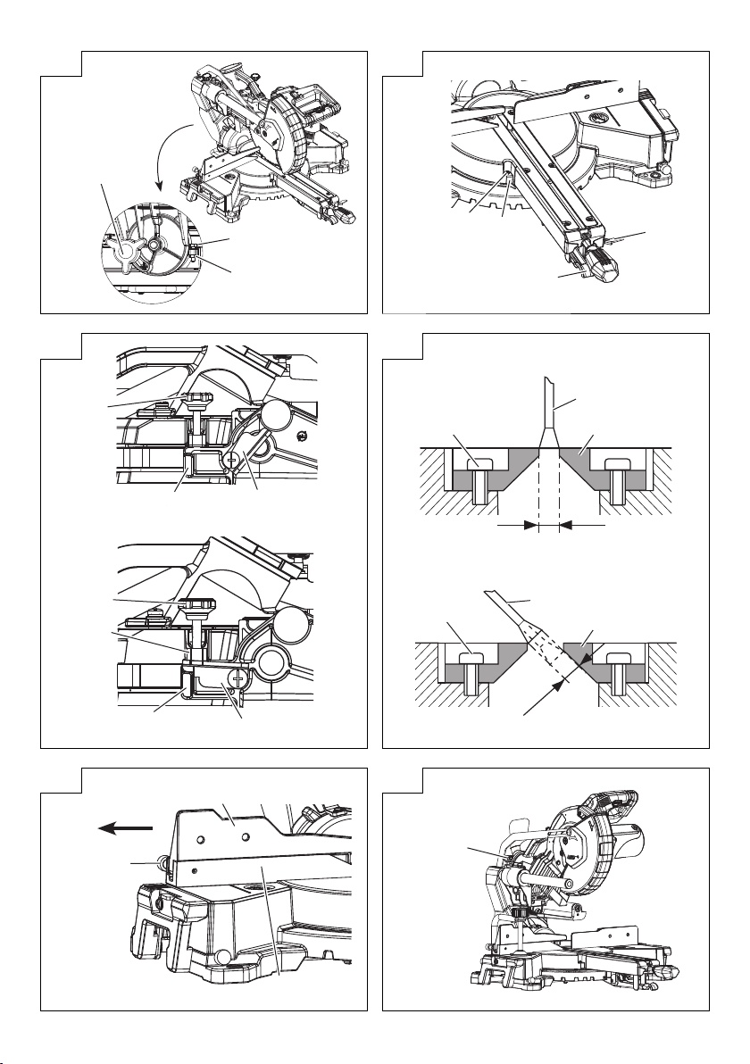
6. Installing the dust bag and vise (Fig. 1)
Install the dust bag onto the dust port on the miter saw.
Fit the connecting tube of dust bag and the dust port
together.
To empty the dust bag, pull out the dust bag assembly
from dust port. Open zipper on underside of bag and
empty into waste container. Check frequently and
empty the dust bag before it gets full.
NOTE
The dust bag should be angled toward the right side
of the saw for best results. This will also avoid any
interference during the saw operation.
CAUTION
Empty the dust bag frequently to prevent the duct and
the lower guard from becoming clogged.
Sawdust will accumulate more quickly than normal
during bevel cutting.
WARNING
Do not use this saw to cut and/or sand metals. the
hot chips or sparks may ignite saw dust from the bag
material.
(Attach the vise assembly as shown in Fig. 1 and Fig. 28.)
7. Installation (Fig. 3)
Ensure that the machine is always fi xed to bench.
Attach the power tool to a level, horizontal work bench.
Select 8 mm diameter bolts suitable in length for the
thickness of the work bench.
Bolt length should be at least 40 mm plus the thickness
of the work bench.
For example, use 8 mm × 65 mm bolts for a 25 mm thick
work bench.
8. Installing the holder (Fig. 4)
The holder attached to the rear of the base helps
stabilize the power tool.
Align the holder with the two holes under the rear of the
base, and tighten two screws with a Philip screwdriver.
23
9. Check the lower guard for proper operation
Lower guard is designed to protect the operator from
coming into contact with the saw blade during operation
of the tool.
Always check that the lower guard moves smoothly after
releasing the blade guard locking lever, and covers the
saw blade properly.
WARNING
NEVER OPERATE THE POWER TOOL if the lower
guard does not function smoothly.
10. 90° (0°) Bevel adjustment (Fig. 5)
WARNING
To ensure accurate cuts, alignment should be checked
and adjustments made prior to use.
(1) Loosen bevel lock knob and tilt the cutting arm
completely to the right. Tighten the bevel lock knob.
(2) Place a combination square on the miter table with the
ruler against the table and the heel of the square against
the saw blade as show in Fig. 5.
(3) If the blade is not 90° square with the miter table, loosen
the bevel lock knob, tilt the cutting head to the left, loosen
the lock nut on the bevel angle adjustment bolt and use a
10 mm spanner to adjust the bevel angle adjustment bolt
depth in or out to increase or decrease the bevel angle.
(4) Tilt the cutting arm back to the right at 90° bevel and
recheck for alignment.
(5) Repeat steps 1 through 4 if further adjustment is needed.
(6) Tighten bevel lock knob and lock nut when alignment is
achieved.
11. 90° Bevel pointer adjustment (Fig. 6)
(1) When the blade is exactly 90° (0°) to the table, loosen
the bevel pointer screw using a #2 Phillips screwdriver.
(2) Adjust bevel pointer to the “0” mark on the bevel scale
and retighten the screw.
12. 45° Left bevel adjustment (Fig. 7)
(1) Loosen the bevel lock knob and tilt the cutting head
completely to the left.
(2) Using a combination square, check to see if the blade is
45° to the table.
(3) If the blade is not at 45° to the miter table, tilt the cutting
arm to the right, loosen the lock nut and use a 10 mm
spanner to adjust the stop bolt depth in or out to increase
or decrease the bevel angle.
(4) Tilt the cutting arm to the left to 45° bevel and recheck for
alignment.
(5) Repeat steps 1 through 4 until the blade at 45° to the
miter table.
(6) Tighten bevel lock knob and lock nut when alignment is
achieved.
13. Miter angle adjustment
The slide compound miter saw scale can be easily read,
showing miter angles from 0° to 48° to the left and right.
The miter saw table has nine of the most common angle
settings with positive stops at 0°, 15°, 22.5°, 31.6°,
and 45°. These positive stops position the blade at the
desired angle quickly and accurately. Follow the process
below for quickest and most accurate adjustments.
Adjusting miter angles: (Fig. 8)
(1) Lift up the quick-cam locking lever to unlock the
table.
(2) Move the table while lifting up on the positive stop
locking lever to align the pointer to the desired
degree measurement.
(3) Lock the table into position by pressing down the
quick-cam locking lever.
Miter pointer adjustment:
(1) Move the table to the 0° positive stop.
(2) Loosen the screw that holds the miter pointer with a
Phillips screwdriver.
(3) Adjust the pointer to the 0° mark and retighten the
screw.
Page 24

English
14. Adjusting cutting depth
The maximum depth travel of the cutting head was set at
the factory.
(1) Setting the maximum width travel of the cutting head,
follow the below steps: (Fig. 9-a)
Turn the stop knob counterclockwise until the stop knob
is not protruding out of the stop seat while moving the
cutting head upward.
Rotate the anchor plate clockwise.
Recheck the blade depth by moving the cutting head
front to back through the full motion of a typical cut along
the control arm.
(2) Setting the maximum height travel of the cutting head,
follow the below steps: (Fig. 9-b)
Turn the stop knob counterclockwise until the stop knob
is not protruding out of the stop seat while moving the
cutting head upward.
Rotate the anchor plate counterclockwise to touch the
stop block.
Make sure the stop seat touches the anchor plate
completely.
15. Setting the cutting depth (Fig. 9-b)
The depth of cut can be preset for even and repetitive
shallow cuts.
(1) Adjust the cutting head down until the teeth of the blade
are at the desired depth.
(2) While holding the upper arm in that position, turn the stop
knob until it touches the anchor plate.
(3) Recheck the blade depth by moving the cutting head
front to back through the full motion of a typical cut along
the control arm.
NOTE
If the anchor plate becomes loose, it can interfere with
raising and lowering the cutting head. The anchor plate
must be tightened in horizontal position as shown in
Fig. 9-b.
PRIOR TO CUTTING
1. Positioning the table insert
Table inserts are installed on the turntable. When
shipping the tool from the factory, the table inserts are
so fi xed that the saw blade does not contact them. The
burr of the bottom surface of the workpiece is remarkably
reduced, if the table insert is fi xed so that the gap
between the side surface of the table insert and the saw
blade will be minimum. Before using the tool, eliminate
this gap in accordance with the following procedure.
(1) Right angle cutting
Loosen the three 4 mm machine screws, then secure
the left side table insert and temporarily tighten the 4 mm
machine screws of both ends. Then fi x a workpiece (about
200 mm wide) with the vise assembly and cut it off . After
aligning the cutting surface with the edge of the table
insert, securely tighten the 4 mm machine screws of both
ends. Remove the workpiece and securely tighten the
4 mm center machine screw. Adjust the right hand table
insert in the same way.
(2) Left bevel angle cutting
Adjust the table insert in the manner shown in Fig. 10-b
following the same procedure for right angle cutting.
CAUTION
After adjusting the table insert for right angle cutting, the
table insert will be cut to some extent if it is used for bevel
angle cutting.
When bevel cutting operation is required, adjust the
table insert for bevel angle cutting.
2. Use of sub fence
WARNING
The sub fence must be extended when making any left
angle bevel cut. Failure to extend the sub fence will not
allow enough space for the blade to pass through which
could result in serious injury. At extreme miter or bevel
angles the saw blade may also contact the fence.
This power tool is equipped with a sub fence.
In the case of direct angle cutting use the sub fence.
Then, you can realize stable cutting of the material with a
wide back face.
When left angle cutting, loosen the lock knob, then slide
the sub fence outward, as shown in Fig. 11.
NOTE
When transporting the saw, always secure the sub fence
in the collapsed position and lock it.
3. Securing the workpiece
WARNING
Always clamp or vise to secure the workpiece to the
fence; otherwise the workpiece might be thrust from the
table and cause bodily harm.
4. Slide carriage system (Fig. 12)
WARNING
To reduce the risk of injury, return slide carriage to the
full rear position after each crosscut operation.
For chop cutting operations on small workpieces, slide
the cutting head assembly completely toward the rear of
the unit and tighten the slide securing knob.
To cut wide boards up to 305 mm, the slide securing
knob must be loosened to allow the cutting head slide
freely.
5. Quick-cam locking lever operation (Fig. 13)
If miter angles required are NOT one of the nine positive
stops, the miter table can be locked at any angle
between these positive stops by using the quick-cam
locking lever.
Unlock the miter table by lifting up on the quick-cam
locking lever. While holding the positive stop locking
lever up, grasp the miter handle and move the table left
or right to the desired angle. Release the positive stop
locking lever. Press down on the quick-cam locking lever
until it locks the table in place.
6. The laser guide
WARNING
● For your own safety, never connect the plug to power
source outlet until the adjustment steps are complete
and you have read and understood the safety and
operational instructions.
● Your tool is equipped with a laser guide using a Class
1M laser guide. The laser guide allows you to preview
the saw blade path on the workpiece to be cut before
starting the miter saw. The saw must be connected to the
power source and the laser on/off switch must be turned
on for the laser line to show.
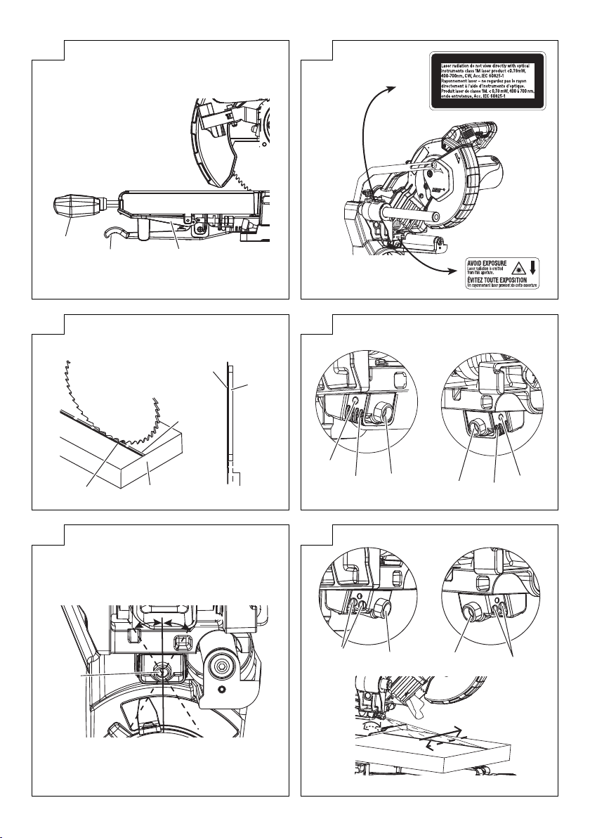
(1) Avoid direct eye contact (Fig. 14)
WARNING
* AVOID EXPOSURE
Laser radiation is emitted from this aperture.
CAUTION
● Use of controls or adjustments or performance of
procedures may result in hazardous radiation exposure.
● The use of optical instruments with this product will
increase eye hazard.
WARNING
Do not attempt to repair or disassemble the laser. If
unqualifi ed persons attempt to repair this laser product,
serious injury may result. Any repair required on this
laser product should be performed by a qualifi ed service
dealer.
24
Page 25

English
(2) Checking laser line alignment (Fig. 15)
(a) Set the saw to a 0° miter and 0° bevel setting.
(b) Use a combination square to mark a 90° angled running
across the top of a board. This line will serve as the
pattern line to adjust the laser. Place the board on the
saw table.
(c) Carefully lower the saw head down to align the saw blade
with the pattern line. Position the saw blade to the left,
side of the “pattern line” depending on your preference
for the laser line location. Lock the board in place with
the hold-down clamp.
(d) With the saw plugged in, turn on the laser guide. Your
saw has been preset with the laser line to the left side of
the blade.
(e) Lower saw blade to pattern line and if blade is not fl ush
with the pattern line, adjust as follow the instructions
listed below under “Adjusting the angle of the laser line”
paragraph and “Aligning the laser line” paragraph.
(3) Adjusting the angle of the laser line (Fig. 16, 17)
(a) After sliding the motor head forward, remove two rivets
on two sides of the laser housing and take the laser
housing off to reveal the laser marker. (Fig. 16)
(b) Turn the laser marker in the desired direction to adjust
the laser angle. (Fig. 17)
NOTE
Do not adjust the laser more than ¼ turn in either
direction as this may damage the laser.
(4) Aligning the laser line. (Fig. 16, 18)
(a) Loosen only ½ turn at a time the four set screws.
(Fig. 18)
(b) Adjust laser marker by turning the left side set screws
clockwise to shift the laser line to the right. To shift the
laser line to the left, turn the right side set screws ½ turn
at a time.
(c) Once alignment of the laser is achieved, tighten only ½
turn at a time the four set screws.
(d) After fi nishing the laser adjustment, replace the laser
housing on the laser marker and then tighten the two
rivets. (Fig. 16)
PRACTICAL APPLICATIONS
WARNING
○ To avoid personal injury, never remove or place a
workpiece on the table while the tool is being operated.
○ Never place your limbs inside of the line next to warning
sign while the tool is being operated (see Fig. 19). This
may cause hazardous conditions.
CAUTION
○ It is dangerous to remove or install the workpiece while
the saw blade is turning.
○ When sawing, clean off the shavings from the turntable.
○ If the shavings accumulate too much, the saw blade from
the cutting material will be exposed. Never subject your
hand or anything else to go near the exposed blade.
NOTE
Prior to operating the switch, make sure to check the
stability of the tool by setting the angle and turn to
conduct a trial cutting run without using a workpiece.
1. Switch operation (Fig. 20)
(1) Turning the saw on
This miter saw is equipped with a trigger switch. Squeeze
the trigger switch to turn the miter saw ON. Release the
trigger switch to turn the saw OFF.
(2) Turning the laser guide on
Press the laser switch to turn it ON, and press again to
turn it OFF.
WARNING
Make the ON/OFF switch childproof. Insert a padlock,
or chain with padlock, through the hole in the trigger
and lock the tool’s switch, preventing children and other
unqualifi ed users from turning the machine on.
2. Using the Vise Assembly (Standard accessory)
(1) The vise assembly can be mounted on the base.
(2) Turn the vise lock knob and securely fi x the vise
assembly.
(3) Turn the upper knob and securely fi x the workpiece in
position (Fig. 21).
NOTE
When using the vise, make sure that the tool is free of
any excessive contact when the unit is swing or slide.
WARNING
Always fi rmly clamp or vise to secure the workpiece to
the fence; otherwise the workpiece might be thrust from
the table and cause bodily harm.
3. Cutting Operation
(1) As shown in Fig. 22 the width of the saw blade is the
width of the cut. Therefore, slide the workpiece to the
right (viewed from the operator’s position) when length
ⓑ is desired, or to the left when length ⓐ is desired.
If a laser marker is used, align the laser line with the left
side of the saw blade, and then align the ink line with the
laser line.
(2) Once the saw blade reaches maximum speed, push the
handle down carefully until the saw blade approaches
the workpiece.
(3) Once the saw blade contacts the workpiece, push the
handle down gradually to cut into the workpiece.
(4) After cutting the workpiece to the desired depth, turn the
power tool OFF and let the saw blade stop completely
before raising the handle from the workpiece to return it
to the full retract position.
CAUTION
Increased pressure on the handle will not increase the
cutting speed.
On the contrary, too much pressure may result in
overload of the motor and/or decreased cutting
effi ciency.
WARNING
● Confi rm that the trigger switch is turned OFF and the
power plug has been removed from the receptacle
whenever the tool is not in use.
● Always turn the power off and let the saw blade stop
completely before raising the handle from the workpiece.
If the handle is raised while the saw blade is still rotating,
the cut-off piece may become jammed against the saw
blade causing fragments to scatter about dangerously.
● Every time one cutting or deep-cutting operation is
fi nished, turn the trigger switch off , and check that the
saw blade has stopped. Then raise the handle, and
return it to the full retract position.
● Be absolutely sure to remove the cut material from the
top of the turntable, and then proceed to the next step.
● Continued cutting operation can result in overload of the
motor. Touch the motor and if it's hot, stop your cutting
operation at once and rest for 10 minutes or so, and then
restart your cutting operation.
4. Cutting wide workpieces (Slide cutting)
(1) Workpieces up to 65 mm high and 280 mm wide:
Loosen the slide securing knob (see
handle and slide the saw blade forward.
Then press down on the handle and slide the saw blade
backward to cut the workpiece as indicated in Fig. 23.
This facilitates cutting of workpieces of up to 65 mm in
height and 280 mm in width.
(2) Workpieces up to 54 mm high and 305 mm wide:
Workpieces of up to 54 mm in height and up to 305 mm
in width can be cut in the same manner as described in
paragraph 4-(1) above on page 25.
25
Fig. 1), grip the
Page 26

English
CAUTION
● If the handle is pressed down with excessive or lateral
force, the saw blade may vibrate during the cutting
operation and cause unwanted cutting marks on the
workpiece, thus reducing the quality of the cut.
Accordingly, press the handle down gently and carefully.
● In slide cutting, gently push the handle back (rearwards)
in a single, smooth operation.
Stopping the handle movement during the cut will cause
unwanted cutting marks on the workpiece.
WARNING
● For slide cutting, follow the procedures indicated above
in Fig. 23.
Forward slide cutting (toward the operator) is very
dangerous because the saw blade could kick upward
from the workpiece. Therefore, always slide the handle
away from the operator.
● Always return the carriage to the full rear position after
each crosscut operation in order to reduce the risk of
injury.
● Never put your hand on the miter handle during the
cutting operation because the saw blade comes close to
the miter handle when the motor head is lowered.
5. Bevel cutting procedures
WARNING
The sub fence must be extended when making any
bevel cut. Failure to extend the sub fence will not allow
enough space for the blade to pass through which could
result in serious injury. At extreme miter or bevel angles
the saw blade may also contact the fence.
(1) When a bevel cut is required, loosen the bevel lock knob
by turning it clockwise. (Fig. 24)
(2) Tilt the cutting head to the desired angle, as shown on
the bevel scale.
(3) The blade can be positioned at any angle, from a 90°
straight cut (0° on the scale) to a 45°. Tighten the bevel
lock knob to lock the cutting head in position. Positive
stops are provided at 0° and 45°.
(4) Turn the laser guide on and position the workpiece on
the table for pre-alignment of your cut.
WARNING
When the workpiece is secured on the left or right side
of the blade, the short cut-off portion will come to rest
on the right or left side of the saw blade. Always turn the
power off and let the saw blade stop completely before
raising the handle from the workpiece.
If the handle is raised while the saw blade is still rotating,
the cut-off piece may become jammed against the saw
blade causing fragments to scatter about dangerously.
When stopping the bevel cutting operation halfway, start
cutting after pulling back the motor head to the initial
position.
Starting from halfway, without pulling back, causes the
lower guard to be caught in the cutting groove of the
workpiece and to contact the saw blade.
CAUTION
● If not tightened fi rmly enough the motor head might
suddenly move or slip, causing injuries. Be sure to
tighten the motor head section enough so it will not
move.
● Always check that the bevel lock knob is secured and
the motor head is clamped. If you attempt angle cutting
without clamping the motor head, then the motor head
might shift unexpectedly causing injuries.
6. Miter cutting procedures (Fig. 25)
(1) Unlock the miter table by lifting up on the quick-cam
locking lever.
(2) While raising the positive stop locking lever up, grasp
the miter handle and rotate the table left or right to the
desired angle.
(3) Release the positive stop locking lever and set the table
at the desired angle, making sure the lever snaps into
place.
(4) Once the desired miter angle is achieved, press down
on the quick-cam locking lever to secure the table into
position.
(5) If the desired miter angle is NOT one of the nine positive
stops noted above, simply lock the table at the desired
angle by pressing down on the quick-cam locking lever.
(6) Turn the laser guide on and position the workpiece on
the table for pre-alignment of your cut.
CAUTION
Always check that the miter handle is secured and the
turntable is clamped.
If you attempt angle cutting without clamping the
turntable, then the turntable might shift unexpectedly
causing injuries.
NOTE
○ Positive stops are provided at the right and left of the 0°
center setting, at 15°, 22.5°, 31.6° and 45° settings.
Check that the miter scale and the tip of the indicator are
properly aligned.
○ Operation of the saw with the miter scale and indicator
out of alignment will result in poor cutting precision.
7. Compound cutting procedures
Compound cutting can be performed by following the
instructions in 4 to 6 above. For maximum dimensions
for compound cutting, refer to “SPECIFICATIONS” table
on page 22.
CAUTION
Always secure the workpiece with the right or left
hand and cut it by sliding the round portion of the saw
backwards with the other hand.
It is very dangerous to rotate the turntable to the left
during compound cutting because the saw blade may
come into contact with the hand that is securing the
workpiece.
In case of compound cutting (angle + bevel) by left bevel,
extend the sub fence fully before cutting operation.
Please confi rm that sub fence does not interfere with
other parts before attempting compound cutting.
8. Groove cutting procedures
Grooves in the workpiece can be cut as indicated in
Fig. 26 by adjusting the stop knob.
Cutting depth adjustment procedure:
(1) Turn the anchor plate on the direction shown in
Fig. 27.
Lower the motor head, and turn the stop knob by
hand. (where the head of the stop knob contacts the
anchor plate.)
(2) Adjust to the desired cutting depth by setting the
distance between the saw blade and the surface of
the turntable (see ⓑ in Fig. 27).
NOTE
When cutting a single groove at either end of the
workpiece, remove the unneeded portion with a chisel.
9. Cutting easily-deformed materials, such as
aluminum sash
Materials such as aluminum sash can easily deform
when tightened too much in a vise assembly. This will
cause ineffi cient cutting and possible overload of the
motor.
When cutting such materials, use a wood plate to protect
the workpiece as shown in Fig. 28-a. Set the wood plate
near the cutting section.
When cutting aluminum materials, coat the saw blade
with cutting oil (non-combustible) to achieve smooth
cutting and a fi ne fi nish.
In addition, in case of a U-shaped workpiece, use the
wood plate as shown in Fig. 28-b to ensure stability in
the lateral direction, and clamp it near the cutting section
of the workpiece and tighten it using both the vise
assembly and the clamp available in the market.
26
Page 27

English
SAW BLADE MOUNTING AND
DISMOUNTING
WARNING
● To prevent an accident or personal injury, always turn off
the trigger switch and disconnect the power plug from
the receptacle before removing or installing a saw blade.
If cutting work is done in a state where the 8 mm bolt is
not suffi ciently tightened, the 8 mm bolt can get loose,
the blade can come off , and the lower guard can get
damaged, resulting in injuries.
Also, check that the 8 mm bolts are properly tightened
before plugging the power plug into the receptacle.
● If the 8 mm bolts are attached or detached using tools
other than the 13 mm wrench (standard accessory),
excessive or improperly tightening occurs, resulting in
injury.
1. Dismounting the blade (Fig. 29-a, Fig. 29-b, Fig. 29-c
and Fig. 29-d)
(1) Unplug the power cord from the outlet.
(2) Raise the cutting head to the upright position and slide
the cutting head completely toward the rear of the unit
and tighten the slide securing knob.
(3) Push slightly on the blade guard locking lever and then
raise the lower guard to the uppermost position.
(4) While holding the lower guard, remove the cover plate
screw with a Phillips screwdriver.
(5) Rotate the cover plate to expose the 8 mm bolt.
(6) Place the blade end spanner over the 8 mm bolt.
(7) Locate the spindle lock on the motor.
(8) Press the spindle lock, holding it in fi rmly while turning
the blade clockwise. The spindle lock will then engage
and lock the arbor. Continue to hold the spindle lock,
while turning the spanner clockwise to loosen the
8 mm bolt.
(9) Remove the 8 mm bolt, washer (B) and the blade. Do not
remove the washer (A).
NOTE
○ If the spindle lock cannot be easily pressed in to lock the
spindle, turn the 8 mm bolt with 13 mm wrench (standard
accessory) while applying pressure on the spindle lock.
The saw blade spindle is locked when the spindle lock is
pressed inward.
○ Pay attention to the pieces removed, noting their position
and direction they face. Wipe the washer (B) clean from
any sawdust before installing a new blade.
WARNING
When mounting the saw blade, confi rm that the rotation
indicator mark on the saw blade and the rotation direction
of the lower guard (see Fig. 1) are properly matched.
CAUTION
● Confi rm that the spindle lock has returned to the retract
position after installing or removing the saw blade.
● Tighten the 8 mm bolt so it does not come loose during
operation.
Confi rm the 8 mm bolt has been properly tightened
before the power tool is started.
2. Mounting the saw blade
WARNING
Unplug the miter saw before changing/installing the
blade.
(1) Install a 216 mm blade with arbor, making sure the
rotation arrow on the blade matches the clockwise
rotation arrow on the lower guard, and the blade teeth
are pointing downward.
(2) Place washer (B) against the blade. Thread the 8 mm
bolt on arbor in a counterclockwise direction.
NOTE
Make sure the fl ats of the washers are engaged with the
fl ats on the arbor shaft. Also, the fl at side of the washer
must be placed against the blade.
(3) Place the blade spanner on the 8 mm bolt.
(4) Press the spindle lock, holding it in fi rmly while turning
the blade counterclockwise. When it engages, continue
to press the spindle lock in, while tightening the 8 mm
bolt securely.
(5) Rotate the cover plate back to its original position until
the slot in the cover plate engages with the hole of cover
plate screw.
While holding the lower guard at the uppermost position,
tighten the cover plate screw with a Phillips screwdriver.
(6) Lower the lower guard and verify that operation of the
guard and blade guard locking lever do not bind or stick.
(7) Be sure the spindle lock is released so the blade turns
freely.
CAUTION
Never attempt to install saw blades larger than 216 mm
in diameter.
Always install saw blades that are 216 mm in diameter or
less.
MAINTENANCE AND INSPECTION
WARNING
To avoid an accident or personal injury, always confi rm
that the trigger switch is turned OFF before performing
any maintenance or inspection of this tool.
Report to qualifi ed person as soon as possible, if you
discover the fault of machine including guards or blade
saw.
1. Inspecting the saw blade
Always replace the saw blade immediately upon the fi rst
sign of deterioration or damage.
A damaged saw blade can cause personal injury and
a worn saw blade can cause ineff ective operation and
possible overload to the motor.
CAUTION
Never use a dull saw blade. When a saw blade is dull,
its resistance to the hand pressure applied by the tool
handle tends to increase, making it unsafe to operate the
power tool.
2. Inspecting the mounting screws
Regularly inspect all mounting screws and ensure that
they are properly tightened. Should any of the screws
be loose, re-tighten them immediately. Failure to do so
could result in serious hazard.
3. Inspecting the carbon brushes (Fig. 30)
Replace both carbon brushes when either has less than
6 mm length of carbon remaining, or if the spring or wire
is damaged or burned. To inspect or replace brushes,
fi rst unplug the saw. Then remove the brush cap on the
side of the motor. Remove the cap cautiously, because it
is springloaded. Then pull out the brush and replace.
Replace for the other side. To reassemble reverse the
procedure. The ears on the metal end of the assembly
go in the same hole the carbon part fi ts into. Tighten the
cap snugly, but do not overtighten.
NOTE
To reinstall the same brushes, fi rst make sure the
brushes go back in the way they came out. This will
avoid a break-in period that reduces motor performance
and increases wear.
4. Maintenance of the motor
The motor unit winding is the very “heart” of the power
tool. Exercise due care to ensure the winding does not
become damaged and/or wet with oil or water.
5. Replacing supply cord
If the supply cord of Tool is damaged, the Tool must be
returned to HiKOKI Authorized Service Center for the
cord to be replaced.
27
Page 28

English
6. Inspecting the lower guard for proper operation
Before each use of the tool, test the lower guard (Fig. 1)
to assure that it is in good condition and that it moves
smoothly.
Never use the tool unless the lower guard operates
properly and it is in good mechanical condition.
7. Storage
After operation of the tool has been completed, check
that the following has been performed:
(1) Trigger switch is in OFF position,
(2) Power plug has been removed from the receptacle,
When the tool is not in use, keep it stored in a dry place
out of the reach of children.
CAUTION
In the operation and maintenance of power tools, the
safety regulations and standards prescribed in each
country must be observed.
8. Lubrication
Lubricate the following sliding surfaces once a month
to keep the power tool in good operating condition for a
long time.
Use of machine oil is recommended.
Oil supply points:
* Rotary portion of hinge
* Rotary portion of holder (A)
* Rotary portion of vise assembly
9. Cleaning (Fig. 31)
Clean the machine, duct and lower guard by blowing
with dry air from an air gun or other tool.
Periodically remove chips, dust and other waste material
from the surface of the power tool, especially from the
inside of the lower guard with a damp, soapy cloth. To
avoid a malfunction of the motor, protect it from contact
with oil or water.
If the laser line becomes invisible due to chips and the
like adhered onto the window of the laser marker’s lightemitting section, wipe and clean the window with a dry
cloth or a soft cloth moistened with soapy water, etc.
SELECTING ACCESSORIES
The accessories of this machine are listed on page 171.
CAUTION
Repair, modifi cation and inspection of HiKOKI Power
Tools must be carried out by a HiKOKI Authorized
Service Center.
Especially laser device should be maintained by the
authorized agent by laser manufacturer.
Always assign the repair of laser device to HiKOKI
Authorized Service Center.
In the operation and maintenance of power tools, the
safety regulations and standards prescribed in each
country must be observed.
NOTE
Due to HiKOKI’s continuing program of research and
development the specifi cations herein are subject to change
without prior notice.
Information concerning airborne noise
The measured values were determined according to
EN62841 and declared in accordance with ISO 4871.
Measured A-weighted sound power level: 107 dB (A).
Measured A-weighted sound pressure level: 94 dB (A).
Uncertainty K: 3 dB (A).
Wear hearing protection.
The declared noise emission value has been measured in
accordance with a standard test method and may be used
for comparing one tool with another;
It may also be used in a preliminary assessment of exposure.
WARNING
○ The noise emissions during actual use of the power tool
can diff er from the declared values depending on the
ways in which the tool is used especially what kind of
workpiece is processed.
○ Identify safety measures to protect the operator that
are based on an estimation of exposure in the actual
conditions of use (taking account of all parts of the
operating cycle such as the times when the tool is
switched off and when it is running idle in addition to the
trigger time).
Information for power supply system to be used with
electric tools provided with rated voltage 230 V~
Switching operations of electric apparatus cause voltage
fl uctuations.
The operation of this electric tool under unfavorable mains
conditions can have adverse eff ects to the operation of other
electric apparatus.
With a mains impedance equal or less than 0.29 Ohms there
will probably be no negative eff ects.
Usually, the maximum permissible mains impedance will
not be exceeded when the branch to the power outlet is fed
from a junction box with a service capacity of 25 ampere or
higher.
In case of power failure, or when the power plug is pulled
out, immediately return the switch to OFF position. This
prevents an uncontrolled restart.
GUARANTEE
We guarantee HiKOKI Power Tools in accordance with
statutory/country specifi c regulation. This guarantee does
not cover defects or damage due to misuse, abuse, or
normal wear and tear. In case of complaint, please send
the Power Tool, undismantled, with the GUARANTEE
CERTIFICATE found at the end of this Handling instruction,
to a HiKOKI Authorized Service Center.
28
Page 29

English
TROUBLESHOOTING
Use the inspections in the table below if the tool does not operate normally. If this does not remedy the problem, consult your
dealer or the HiKOKI Authorized Service Center.
Power tool
Symptom Possible cause Remedy
Tool doesn’t run Trigger switch is in OFF position Turn on the switch.
The power cord is not plugged in properly. Plug the power cord correctly.
Tool suddenly stopped Tool was overburdened. Get rid of the problem causing the
Cannot be tilted The clamp lever has not been loosened. Loosen the clamp lever and then tilt the tool.
Sawblade is dull The sawblade is worn down or missing
Cannot cut with precision The operation parts of the tool are not fully
Motor head cannot be
lowered
teeth.
Bolt is loose. Tighten the bolt.
The sawblade has been installed in reverse. Install the sawblade in the correct direction.
fi xed.
Material cannot be fi xed in the correct
position.
Blade guard locking lever is not released. Release the blade guard locking lever and
overburden.
After adjusting the loosened component,
make sure to tighten it once again.
Exchange with a new sawblade.
Fully fi x the clamp lever and bevel lock
knob.
Remove any foreign material from the fence
or turntable.
In some cases, proper position cannot be
fi xed due to a curve in the material.
Try to fi x a fl at surface with the fence or
turntable.
then lower the motor head.
29
Page 30

Deutsch
(Übersetzung der Original-Gebrauchsanweisung)
ALLGEMEINE
SICHERHEITSHINWEISE FÜR
ELEKTROGERÄTE
WARNUNG
Bitte beachten Sie sämtliche mit diesem Elektrogerät
gelieferten Sicherheitshinweise, Anweisungen,
Illustrationen und technischen Angaben.
Wenn die nachfolgenden Anweisungen nicht befolgt
werden, kann es zu Stromschlag, Brand und/oder
ernsthaften Verletzungen kommen.
Bitte bewahren Sie alle Warnhinweise und
Anweisungen zum späteren Nachschlagen auf.
Der Begriff „Elektrowerkzeug“ in den Warnungen
bezieht sich auf Ihr netzbetriebenes (kabelgebundenes)
Elektrowerkzeug.
1) Sicherheit im Arbeitsbereich
a) Sorgen Sie für einen sauberen und gut
ausgeleuchteten Arbeitsbereich.
Zugestellte oder dunkle Bereiche ziehen Unfälle
förmlich an.
b) Verwenden Sie Elektrowerkzeuge niemals an
Orten, an denen Explosionsgefahr besteht,
wie zum Beispiel in der Nähe von leicht
entfl ammbaren Flüssigkeiten, Gasen oder
Stäuben.
Bei der Arbeit mit Elektrowerkzeugen kann es zu
Funkenbildung kommen, wodurch sich Stäube oder
Dämpfe entzünden können.
c) Sorgen Sie bei der Arbeit mit Elektrowerkzeugen
dafür, dass sich keine Zuschauer (insbesondere
Kinder) in der Nähe befi nden.
Wenn Sie abgelenkt werden, können Sie die
Kontrolle über das Werkzeug verlieren.
2) Elektrische Sicherheit
a) Elektrowerkzeuge müssen mit passender
Stromversorgung betrieben werden. Nehmen
Sie niemals irgendwelche Änderungen am
Anschlussstecker vor. Verwenden Sie bei
Elektrowerkzeugen mit Schutzkontakt (geerdet)
niemals Adapterstecker.
Stecker im Originalzustand und passende
Steckdosen reduzieren das Stromschlagrisiko.
b) Vermeiden Sie Körperkontakt mit geerdeten
Gegenständen wie Rohrleitungen, Heizungen,
Herden oder Kühlschränken.
Bei Körperkontakt mit geerdeten Gegenständen
besteht ein erhöhtes Stromschlagrisiko.
c) Setzen Sie Elektrowerkzeuge niemals Regen
oder sonstiger Feuchtigkeit aus.
Wenn Flüssigkeiten in ein Elektrowerkzeug
eindringen, erhöht sich das Stromschlagrisiko.
d) Verwenden Sie das Anschlusskabel nicht
missbräuchlich. Tragen Sie das Elektrowerkzeug
niemals am Stromkabel, ziehen Sie es nicht
damit heran und ziehen Sie den Stecker nicht
am Anschlusskabel aus der Steckdose.
Halten Sie das Anschlusskabel von Hitzequellen,
Öl, scharfen Kanten und beweglichen Teilen
fern.
Beschädigte oder verdrehte Anschlusskabel
erhöhen das Stromschlagrisiko.
e) Verwenden Sie, wenn Sie ein Elektrowerkzeug
im Freien benutzen, ein für den Außeneinsatz
geeignetes Verlängerungskabel.
Ein für den Außeneinsatz geeignetes Kabel
vermindert das Stromschlagrisiko.
f) Falls sich der Betrieb des Elektrowerkzeugs
in feuchter Umgebung nicht vermeiden lässt,
verwenden Sie eine Stromversorgung mit
Fehlerstromschutzeinrichtung (Residual
Current Device, RCD).
Durch den Einsatz einer
Fehlerstromschutzeinrichtung wird das Risiko eines
elektrischen Schlages reduziert.
3) Persönliche Sicherheit
a) Bleiben Sie wachsam, achten Sie auf das, was
Sie tun, und setzen Sie Ihren Verstand ein, wenn
Sie mit Elektrowerkzeugen arbeiten.
Benutzen Sie keine Elektrowerkzeuge, wenn
Sie müde sind oder unter Einfl uss von Drogen,
Alkohol oder Medikamenten stehen.
Bei der Arbeit mit Elektrowerkzeugen können bereits
kurze Phasen der Unaufmerksamkeit zu schweren
Verletzungen führen.
b) Benutzen Sie eine persönliche
Schutzausrüstung. Tragen Sie immer einen
Augenschutz.
Schutzausrüstung wie Staubmaske, rutschfeste
Sicherheitsschuhe, Schutzhelm und Gehörschutz
senken bei angemessenem Einsatz das
Verletzungsrisiko.
c) Vermeiden Sie unbeabsichtigtes Einschalten.
Achten Sie darauf, dass sich der Schalter
in der Aus- (Off -) Position befi ndet, ehe Sie
das Gerät mit der Stromversorgung und/
oder Batteriestromversorgung verbinden, es
aufheben oder herumtragen.
Das Herumtragen von Elektrowerkzeugen mit
dem Finger am Schalter oder das Herstellen der
Stromversorgung bei betätigtem Schalter zieht
Unfälle regelrecht an.
d) Entfernen Sie sämtliche Einstellwerkzeuge
(Einstellschlüssel), ehe Sie das Elektrowerkzeug
einschalten.
Ein an einem beweglichen Teil des Elektrowerkzeugs
angebrachter Schlüssel kann zu Verletzungen
führen.
e) Überstrecken Sie sich nicht. Achten Sie jederzeit
darauf, sicher zu stehen und das Gleichgewicht
zu bewahren.
Dadurch haben Sie das Elektrowerkzeug in
unerwarteten Situationen besser im Griff .
f) Tragen Sie geeignete Kleidung. Tragen Sie
keine lose Kleidung oder Schmuck. Halten Sie
Ihr Haar und Ihre Kleidung von beweglichen
Teilen fern.
Lose Kleidung, Schmuck oder langes Haar kann von
beweglichen Teilen erfasst werden.
g) Wenn Anschlüsse für Staubabsaug- und -
sammelvorrichtungen vorhanden sind, sorgen
Sie dafür, dass diese richtig angeschlossen und
eingesetzt werden.
Durch Entfernen des Staubes können
staubbezogene Gefahren vermindert werden.
h) Lassen Sie es nicht zu, dass die durch häufi gen
Gebrauch von Werkzeugen erworbene
Vertrautheit Sie nachlässig macht und Sie
die Sicherheitsrichtlinien für das Werkzeug
ignorieren.
Eine unvorsichtige Handlung kann in
Sekundenbruchteilen zu schweren Verletzungen
führen.
4) Einsatz und Pfl ege von Elektrowerkzeugen
a) Überbeanspruchen Sie Elektrowerkzeuge nicht.
Benutzen Sie das richtige Elektrowerkzeug für
Ihren Einsatzzweck.
30
Page 31

Das richtige Elektrowerkzeug erledigt seine Arbeit
bei bestimmungsgemäßem Einsatz besser und
sicherer.
b) Benutzen Sie das Elektrowerkzeug nicht, wenn
es sich nicht am Schalter ein- und ausschalten
lässt.
Jedes Elektrowerkzeug, das nicht mit dem Schalter
betätigt werden kann, stellt eine Gefahr dar und
muss repariert werden.
c) Ziehen Sie den Stecker der Stromversorgung
ab und/oder entfernen Sie den Akkupack
vom Elektrowerkzeug, falls abnehmbar, ehe
Sie Einstellarbeiten vornehmen, Zubehörteile
tauschen oder das Elektrowerkzeug verstauen.
Solche präventiven Sicherheitsmaßnahmen
verhindern den unbeabsichtigten Anlauf des
Elektrowerkzeugs und die damit verbundenen
Gefahren.
d) Lagern Sie nicht benutzte Elektrowerkzeuge
außerhalb der Reichweite von Kindern,
lassen Sie nicht zu, dass Personen das
Elektrowerkzeug bedienen, die nicht mit dem
Werkzeug selbst und/oder diesen Anweisungen
vertraut sind.
Elektrowerkzeuge in ungeschulten Händen sind
gefährlich.
e) Wartung von Elektrowerkzeugen und Zubehör.
Prüfen Sie sie auf Fehlausrichtungen,
Leichtgängigkeit beweglicher Teile,
Beschädigungen von Teilen und auf alle
anderen Umstände, die sich auf den Betrieb des
Elektrowerkzeugs auswirken können. Lassen
Sie das Elektrowerkzeug bei Beschädigungen
reparieren, ehe Sie es benutzen.
Viele Unfälle mit Elektrowerkzeugen sind auf
schlechte Wartung zurückzuführen.
f) Halten Sie Schneidwerkzeuge scharf und
sauber.
Richtig gewartete Schneidwerkzeuge mit scharfen
Schneiden bleiben weniger häufi g hängen und sind
einfacher zu beherrschen.
g) Benutzen Sie Elektrowerkzeuge, Zubehör,
Werkzeugspitzen und Ähnliches in
Übereinstimmung mit diesen Anweisungen
– beachten Sie dabei die jeweiligen
Arbeitsbedingungen und die Art der
auszuführenden Arbeiten.
Der Gebrauch des Elektrowerkzeugs für andere
als die vorgesehenen Anwendungen kann zu
gefährlichen Situationen führen.
h) Halten Sie Handgriff e und Greiffl ächen trocken,
sauber und frei von Öl und Fett.
Rutschige Handgriff e und Greiffl ächen lassen keine
sichere Handhabung und Kontrolle des Werkzeugs
in unerwarteten Situationen zu.
5) Service
a) Lassen Sie Ihr Elektrowerkzeug durch
qualifi zierte Fachkräfte und nur unter Einsatz
der passenden Originalersatzteile warten.
Dies sorgt dafür, dass die Sicherheit des
Elektrowerkzeugs nicht beeinträchtigt wird.
VORSICHT
Von Kindern und gebrechlichen Personen fernhalten.
Werkzeuge sollten bei Nichtgebrauch außerhalb der
Reichweite von Kindern und gebrechlichen Personen
aufbewahrt werden.
Deutsch
SICHERHEITSHINWEISE FÜR DIE
GEHRUNGSSÄGE
a) Gehrungssägen sind zum Sägen von Holz oder
holzähnlichen Produkten bestimmt, sie können
nicht mit Trennscheiben zum Schneiden von
Werkstoff en aus Eisen wie Stangen, Stäben, Bolzen
usw. verwendet werden.
Schleifstaub lässt bewegliche Teile wie den unteren
Schutz blockieren. Funken von der Trennscheibe
verbrennen den unteren Schutz, den Sägeschlitzeinsatz
und andere Kunststoff teile.
b) Verwenden Sie Klemmen zur Sicherung des
Werkstücks, wann immer möglich. Wenn das
Werkstück von Hand gestützt wird, müssen Sie
immer einen Mindestabstand von 100 mm zwischen
Ihrer Hand und beiden Seiten des Sägeblatts
einhalten. Nutzen Sie diese Säge nicht zum Sägen
von Teilen, die zu klein sind, um sicher eingespannt
oder mit der Hand gehalten zu werden.
Wenn sich Ihre Hand zu nahe am Sägeblatt befi ndet,
besteht ein höheres Verletzungsrisiko durch Kontakt mit
dem Sägeblatt.
c) Das Werkstück muss feststehen und gegen das
Gitter und den Tisch eingespannt oder festgehalten
werden. Führen Sie das Werkstück nicht zum
Sägeblatt und sägen Sie niemals „freihändig“.
Nicht fi xierte oder sich bewegende Werkstücke können
mit hohen Geschwindigkeiten weggeschleudert werden
und Verletzungen verursachen.
d) Drücken Sie die Säge durch das Werkstück. Ziehen
Sie nicht die Säge durch das Werkstück. Um
einen Schnitt zu machen, heben Sie den Sägekopf
an, ziehen Sie diesen ohne zu sägen über das
Werkstück, starten Sie den Motor, drücken Sie den
Sägekopf nach unten und drücken Sie die Säge
durch das Werkstück.
Beim Sägen während des Ziehens wird das Sägeblatt
wahrscheinlich am Werkstück aufsteigen und die
Sägeblattbaugruppe heftig in Richtung des Bedieners
geschleudert.
e) Bringen Sie Ihre Hände nie in die vorgesehene
Schnittlinie, weder vor noch hinter dem Sägeblatt.
Das Abstützen des Werkstücks „über Kreuz“, d. h.
das Werkstück auf der rechten Seite des Sägeblatts
mit der linken Hand zu halten oder umgekehrt, ist sehr
gefährlich.
f) Greifen Sie mit keiner Hand von beiden Seiten des
Sägeblatts näher als 100 mm hinter das Gitter, um
Sägespäne zu entfernen oder aus irgendeinem
anderen Grund, solange sich das Sägeblatt dreht.
Die Nähe des drehendes Sägeblatts zu Ihrer Hand
könnte unterschätzt werden und Sie könnten sich
schwer verletzen.
g) Untersuchen Sie das Werkstück vor dem Sägen.
Wenn das Werkstück gebogen oder gekrümmt ist,
spannen Sie es mit der nach außen gebogenen
Fläche in Richtung des Gitters ein. Stellen Sie
immer sicher, dass sich kein Spalt zwischen
Werkstück, Gitter und Tisch entlang der Schnittlinie
befi ndet.
Gebogene oder gekrümmte Werkstücke können sich
verdrehen oder verschieben und können beim Sägen
das Sägeblatts blockieren. Das Werkstück sollte frei von
Nägeln und Fremdkörpern sein.
h) Benutzen Sie die Säge nicht, bevor der Tisch frei
von Werkzeugen, Sägespänen usw. ist, und nur das
Werkstück darauf liegt.
Kleine Bruchstücke sowie lose Holzteile oder andere
Gegenstände, die mit dem drehenden Sägeblatt in
Kontakt kommen, können mit hoher Geschwindigkeit
weggeschleudert werden.
31
Page 32

Deutsch
i) Sägen Sie immer nur ein Werkstück auf einmal.
Mehrere Werkstücke übereinander können nicht richtig
eingespannt oder festgeklemmt werden und können das
Sägeblatt beim Sägen blockieren oder sich verschieben.
j) Stellen Sie sicher, dass die Gehrungssäge auf einer
ebenen, stabilen Arbeitsfl äche montiert ist bzw.
steht, bevor Sie sie benutzen.
Eine ebene und stabile Arbeitsfl äche verringert die
Gefahr, dass die Gehrungssäge instabil wird.
k) Planen Sie Ihre Arbeit. Immer wenn Sie die
Einstellung des Neigungs- oder Gehrungswinkels
ändern, sorgen Sie dafür, dass das einstellbare
Gitter richtig eingestellt ist, um das Werkstück
zu halten und nicht gegen das Sägeblatt oder die
Schutzeinrichtung stößt.
Führen Sie ohne Einschalten des Werkzeugs und ohne
Werkstück auf dem Tisch einen vollständigen simulierten
Schnitt mit dem Sägeblatt aus, um sicherzustellen, dass
es nicht zu Zusammenstößen kommt und keine Gefahr
besteht, dass das Gitter angesägt wird.
l) Sorgen Sie für eine angemessene Abstützung, z. B.
durch Tischerweiterungen, Sägeböcke o. Ä., wenn
das Werkstück breiter oder länger ist als der Tisch.
Werkstücke, die länger oder breiter als der
Gehrungssägetisch sind, können umkippen, wenn sie
nicht sicher abgestützt werden. Wenn das abgetrennte
Teil oder das Werkstück umkippt, kann es den unteren
Schutz anheben oder vom drehenden Sägeblatt
weggeschleudert werden.
m) Setzen Sie keine Personen als Ersatz für
Tischerweiterungen bzw. als zusätzliche Stütze ein.
Eine instabile Abstützung des Werkstücks kann dazu
führen, dass das Sägeblatt blockiert oder sich das
Werkstück während des Sägevorgangs verschiebt und
Sie und der Helfer in das drehende Sägeblatt gezogen
werden.
n) Das abgetrennte Teil darf auf keinen Fall gegen
das drehende Sägeblatt geklemmt oder gedrückt
werden.
Wenn es z. B. durch einen Längenanschlag eingeklemmt
wird, kann das abgetrennte Teil gegen das Sägeblatt
verkeilt werden und heftig weggeschleudert werden.
o) Verwenden Sie immer eine Klemme oder eine
Vorrichtung, die für die Aufnahme von runden
Werkstoff en wie Stangen oder Rohren geeignet ist.
Stangen tendieren dazu, beim Sägen wegzurollen,
wodurch das Sägeblatt „beißt“ und das Werkstück mit
Ihrer Hand in das Sägeblatt zieht.
p) Lassen Sie das Sägeblatt die volle Drehzahl
erreichen, bevor es mit dem Werkstück in
Berührung kommt.
Dadurch wird das Risiko verringert, dass das Werkstück
weggeschleudert wird.
q) Wenn das Werkstück oder das Sägeblatt blockiert
wird, schalten Sie die Gehrungssäge aus. Warten
Sie, bis alle beweglichen Teile stillstehen und
ziehen Sie den Stecker aus der Steckdose und/
oder entfernen Sie den Akkupack. Entfernen Sie
anschließend das eingeklemmte Material.
Wenn mit einem eingeklemmten Werkstück weiter
gesägt wird, kann das zu einem Kontrollverlust oder zu
Schäden an der Gehrungssäge führen.
r) Wenn der Schnitt beendet ist, lassen Sie den Schalter
los, halten Sie den Sägekopf heruntergedrückt und
warten Sie, bis sich das Sägeblatt nicht mehr dreht,
bevor Sie das abgetrennte Teil entfernen.
Mit der Hand in die Nähe des Sägeblatts im Leerlauf zu
greifen ist gefährlich.
32
s) Halten Sie den Griff sicher fest, wenn Sie einen
unvollständigen Schnitt ausführen oder wenn
Sie den Schalter loslassen, bevor der Sägekopf
vollständig abgesenkt ist.
Die Bremswirkung der Säge kann dazu führen, dass der
Sägekopf plötzlich nach unten gezogen wird, was zu
Verletzungen führen kann.
VORSICHTSHINWEISE ZUR
VERWENDUNG DER PANEELSÄGE
1. Halten Sie den Boden um die Maschine herum eben, gut
gewartet und frei von losem Material wie z.B. Sägespäne
und abgesägten Stücken.
2. Sorgen Sie für ausreichende allgemeine und örtliche
Beleuchtung.
3. Elektrowerkzeuge nur für die in der Bedienungsanleitung angeführten Anwendungen verwenden.
4. Reparaturen dürfen nur durch autorisierte
Wartungseinrichtungen durchgeführt werden. Der
Hersteller ist nicht verantwortlich für Beschädigungen
oder Verletzungen, die durch Reparatur durch nicht
autorisierte Personen oder durch Mißbrauch des
Werkzeugs verursacht werden.
5. Zur Sicherstellung der Betriebsintegrität von
Elektrowerkzeugen niemals installierte Abdeckungen
oder Schrauben entfernen.
6. Bewegliche Teile und Zubehör nur berühren, wenn das
Werkzeug nicht an die Stromversorgung angeschlossen
ist.
7. Das Werkzeug mit einer geringeren Leistungs-aufnahme
als auf dem Typenschild angezeigt verwenden, da
sonst durch Überlastung die Qualität der bearbeiteten
Oberfl äche bzw. der Wirkungsgrad beeinträchtigt
werden kann.
8. Plastikteile nicht mit Lösungsmittel abwischen.
Lösungsmittel wie Benzin, Verdünner,
Kohlenstoff tetrachlorid oder Alkohol können
Plastikmaterial beschädigen oder Risse verursachen.
Nie mit Lösungsmittel abwischen. Plastikteile mit einem
mit Seifenwasser angefeuchteten weichen Lappen
reinigen.
9. Nur Originalersatzteile von HiKOKI verwenden.
10. Dieses Werkzeug sollte nur zum Auswechseln der
Kohlebürsten zerlegt werden.
11. Die Explosionszeichnung in dieser Bedienungsanleitung
ist nur für autorisierte Wartungseinrichtungen gedacht.
12. Sägen Sie niemals Metall oder Mauerwerk.
13. Ausreichende allgemeine oder lokalisierte Beleuchtung
ist vorgesehen. Vorrat und fertige Werkstücke befi nden
sich in der Nähe der normalen Arbeitsposition der
Bedienung.
14. Tragen Sie ausreichende persönliche Schutzausrüstung,
wenn erforderlich. Dies kann z.B. einschließen:
Gehörschutz zur Verringerung des Risikos von
induziertem Gehörverlust.
Augenschutz zur Verringerung des Risikos von
Augenverletzungen.
Atemschutz zur Verringerung des Risikos von Einatmen
von schädlichem Staub.
Handschuhe zur Handhabung von Sägeblättern
(Sägeblätter sollten möglichst in einem Halter
transportiert werden) und grobem Material.
15. Die Bedienung ist angemessen in Verwendung,
Einstellung und Betrieb der Maschine geschult.
16. Vermeiden Sie es, abgeschnittene oder andere Teile
des Werkstücks aus dem Schneidbereich zu entfernen,
während die Maschine läuft und der Sägekopf nicht in
der Ruheposition ist.
17. Verwenden Sie die Paneelsäge niemals mit den unteren
Schutz in off ener Position verriegelt.
Page 33

18. Stellen Sie sicher, dass sich der untere Schutz glatt
bewegt.
19. Verwenden Sie die Säge nur in gutem Betriebszustand,
angemessen geartet und mit den Schutzvorrichtungen in
Position.
20. Verwenden Sie korrekt geschärfte Sägeblätter.
Beachten Sie die auf dem Sägeblatt angegebene
maximale Drehzahl.
21. Verwenden Sie keine beschädigten oder verformten
Sägeblätter.
22. Verwenden Sie keine aus Hochschnellstahl hergestellten
Sägeblätter.
23. Verwenden Sie nur von HiKOKI empfohlene Sägeblätter.
Das verwendete Sägeblatt muss EN847-1 entsprechen.
24. Die Sägeblätter sollten einen Außendurchmesser im
Bereich von 210 bis 216 mm haben.
25. Wählen Sie das korrekte Sägeblatt für das zu sägende
Material.
26. Betreiben Sie die Paneelsäge niemals mit dem Sägeblatt
zur Seite oder nach oben hin.
27. Stellen Sie sicher, dass das Werkstück frei ist von
Fremdkörpern wie Nägel usw.
28. Wechseln Sie den Tischeinsatz aus, wenn er abgenutzt
ist.
29. Verwenden Sie die Säge nur zum Sägen von Aluminium,
Holz oder ähnlichen Materialien.
30. Verwenden Sie Säge nur zum Sägen von durch den
Hersteller empfohlenen Materialien.
31. Das Verfahren zum Auswechseln des Sägeblatts muss
korrekt durchgeführt werden, einschließlich der Methode
für die Neupositionierung und der Warnung.
32. Schließen Sie die Paneelsäge beim Sägen von Holz an
einen Staubsammler an.
33. Lassen Sie beim Schlitzen Vorsicht walten.
34. Halten Sie das Werkzeug beim Transport bzw. zum
Tragen nicht am Halter. Halten Sie das Werkzeug am
Handgriff anstatt am Halter.
35. Es besteht die Gefahr, daß der Halter aus der Basis
herausrutscht. Halten Sie den Handgriff anstatt des
Halters.
36. Beginnen Sie mit dem Sägen, nachdem der Motor die
maximale Drehzahl erreicht hat.
37. Drücken Sie sofort den Ausschalter (OFF), wenn Sie
eine Störung bemerken.
38. Schalten Sie die Stromversorgung aus und warten
Sie, bis das Sägeblatt angehalten hat, bevor Sie das
Werkzeug warten oder einstellen.
39. Während Sägen einer Gehrung oder eines
Schrägschnitts sollte das Sägeblatt nicht angehoben
werden, bis es vollkommen angehalten hat.
40. Beim Sägebetrieb muss die Paneelsäge in der Richtung
von der Bedienung weg bewegt werden.
41. Beachten Sie beim Sägebetrieb alle restlichen Risiken,
wie Laserstrahlung zu Ihren Augen, ungewollter Zugriff
zu sich bewegenden Teilen am Schlittenmechanismus
der Maschine usw.
42. Achten Sie vor jedem Schnitt darauf, dass die Maschine
stabil ist.
Verwenden Sie nur Sägeblätter, deren maximale
zulässige Geschwindigkeit höher als die
Leerlaufdrehzahl des Werkzeugs ist.
Ersetzen Sie den Laser nicht durch einen anderen Typ.
43. Stehen Sie niemals in einer Reihe mit dem Sägeblatt vor
der Maschine. Stehen Sie immer seitlich des Sägeblatts.
Dies schützt Ihren Körper gegen den möglichen
Rückschlag. Halten Sie die Hände, Finger und Arme fern
vom rotierenden Sägeblatt.
Überkreuzen Sie nicht Ihre Arme, wenn Sie den
Werkzeugarm bedienen.
Deutsch
44. Wenn das Sägeblatt blockiert ist, schalten Sie die
Maschine aus und halten Sie das Werkstück fest, bis
das Sägeblatt vollständig zum Stillstand gekommen ist.
Um den Rückschlag zu vermeiden, darf das Werkstück
nicht bewegt werden, bis die Maschine vollständig zum
Stillstand gekommen ist.
Beheben Sie die Ursache der Blockierung des
Sägeblatts, bevor Sie die Maschine neu starten.
SYMBOLE
WARNUNG
Die folgenden Symbole werden für diese Maschine
verwendet. Achten Sie darauf, diese vor der
Verwendung zu verstehen.
C 8FSHG: Paneelsäge
Der Anwender muss die Bedienungsanleitung
lesen, um das Risiko einer Verletzung zu
verringern.
Tragen Sie immer einen Augenschutz.
Tragen Sie immer einen Gehörschutz.
Nur für EU-Länder
Werfen Sie Elektrowerkzeuge nicht in den
Hausmüll!
Gemäß der Europäischen Richtlinie 2012/19/
EU über Elektro- und Elektronik- Altgeräte
und Umsetzung in nationales Recht müssen
verbrauchte Elektrowerkzeuge getrennt
gesammelt und einer umweltgerechten
Wiederververtung zugeführt werden.
V Volt
Hz Hertz
A Ampere
Leerlaufdrehzahl
no
Konstruktion der Klasse II
---/min Umdrehungen pro Minute
Wechselstrom
STANDARDZUBEHÖR
○ 216 mm TCT-Sägeblat (am Werkzeug angebracht)......1
○ Staubbeutel ...................................................................1
○ 13 mm Steckschlüssel ..................................................1
○ Schraubstocksatz .........................................................1
○ Halter ............................................................................1
○ Gehrungsgriff ................................................................1
Das Standardzubehör kann ohne vorherige
Bekanntmachung jederzeit geändert werden.
VERWENDUNG
Sägen von Aluminiumfensterrahmen und verschiedenen
Holzarten.
33
Page 34

Deutsch
TECHNISCHE DATEN
1. Paneelsäge
Element Modell C 8FSHG
Motor Reihenschlussmotor
Maximale Ausgangsleistung <0,39 mW Laserprodukt KLASSE 1M
Lasermarker
Geeignete Sägeblätter
Spannung (nach Gebiet)*
Leistungsaufnahme* 1030 W 1100 W
Drehzahl ohne Last 5300 min
Max.
SägeAbmessungen
Max.
SägeAbmessungen
Gehrungssägebereich Links 0° – 48° Rechts 0° – 48°
Schrägsägebereich Links 0° – 47° Rechts 0° – 2°
Gesamtsägebereich
Maschinenabmessungen (Breite × Tiefe × Höhe) 528 mm × 725 mm × 495 mm
Gewicht (Netto)** 13,8 kg
* Überprüfen Sie die Angaben auf dem Typenschild, da sich diese je nach dem Verkaufsgebiet ändern.
** Gemäß EPTA-Verfahren 01/2014
Wellenlänge 400 – 700 nm
Lasermedium Laserdiode
Außendurchm. 216 mm
Lochdurchm. 30 mm
110 V
-1
Kopf Drehscheibe Max. Sägeabmessung
(Mit Ankerplatte)
Max. Höhe
00
Gehrung
Schrägschnitt Links 45° 0
Gesamt Links 45°
0
0
Links 45°
oder
Rechts 45°
Links 48°
oder
Rechts 48°
Links 45°
oder
Rechts 45°
Max. Breite
(Ohne Ankerplatte)
Max. Höhe
Max. Breite
(Mit Ankerplatte)
Max. Höhe
Max. Breite
(Ohne Ankerplatte)
Max. Höhe
Max. Breite
(Mit Ankerplatte)
Max. Höhe
Max. Breite
(Ohne Ankerplatte)
Max. Höhe
Max. Breite
(Mit Ankerplatte)
Max. Höhe
Max. Breite
(Ohne Ankerplatte)
Max. Höhe
Max. Breite
(Mit Ankerplatte)
Max. Höhe
Max. Breite
(Ohne Ankerplatte)
Max. Höhe
Max. Breite
Links (Schräg) 0° – 45°, Links (Gehrung) 0°– 45°
Rechts (Schräg) 0°– 45°, Rechts (Gehrung) 0°– 45°
230 V
65 mm
280 mm
54 mm
305 mm
65 mm
203 mm
54 mm
210 mm
65 mm
192 mm
54 mm
199 mm
38 mm
280 mm
26 mm
305 mm
38 mm
203 mm
26 mm
210 mm
34
Page 35

VOR DER VERWENDUNG
VORSICHT
Alle Einstellungen vor Anschluß des Steckers an die
Steckdose durchführen.
1. Stromversorgung
Sicherstellen, daß die zu verwendende Stromversorgung
den Angaben auf dem Typenschild entspricht.
Nicht mit direktem Stromfl uss verwenden oder
Transformatoren wie Boostern. Dadurch kann es zu
Beschädigungen oder Unfällen kommen.
2. Netzschalter
Sicherstellen, daß der Netzschalter ausgeschaltet
ist. Wenn der Stecker bei eingeschaltetem Schalter
an eine Steckdose angeschlossen wird, fängt das
Elektrowerkzeug sofort an zu laufen, und es kann zu
einem schweren Unfall kommen.
3. Verlängerungskabel
Bei Arbeit entfernt von einer Steckdose ein
Verlängerungskabel ausreichender Dicke und
Nennkapazität verwenden. Das Verlängerungskabel so
kurz wie möglich halten.
4. Entfernen Sie das gesamte Verpackungsmaterial,
das am Werkzeug haftet oder damit verbunden ist,
bevor Sie versuchen, es in Betrieb zu nehmen.
5. Lösen des Sperrstifts. (Abb. 2)
Bei der Vorbereitung des Elektrowerkzeugs Werden die
Hauptteile durch einen Verriegelungsstift gesichert.
Drücken Sie den Griff leicht nach unten und ziehen Sie
den Sicherungsstift heraus, um den Sägekopf zu lösen.
HINWEIS
Wenn Sie den Griff etwas absenken, können Sie
den Sicherungsstift einfacher und sicher lösen. Die
verriegelte Position des Sicherungsstifts dient nur zu
Transport und Lagerung.
6. Anbringen von Staubbeutel und Schraubstock
(Abb. 1)
Schließen Sie den Staubbeutel an den Staubabzug der
Gehrungssäge an. Verbinden Sie das Anschlussrohr
des Staubbeutels und den Staubabzug miteinander.
Ziehen Sie zum Entleeren des Staubbeutels die
Staubbeutelbaugruppe vom Staubabzug ab. Öff nen Sie
den Reißverschluss an der Unterseite des Beutels und
leeren Sie ihn in einen Abfallbehälter. Überprüfen Sie
den Staubbeutel oft und leeren Sie ihn, bevor er voll
wird.
HINWEIS
Der Staubbeutel sollte zur rechten Seite der Säge
zeigen, um die besten Ergebnisse zu erzielen. Dadurch
wird auch eine mögliche Berührung während des
Sägens vermieden.
VORSICHT
Leeren Sie den Staubbeutel regelmäßig, um zu
verhindern, dass der Einlass und der untere Schutz
verstopft werden.
Beim Schrägschnitt sammelt sich Sägemehl schneller
als normal an.
WARNUNG
Verwenden Sie diese Säge nicht zum Schneiden und/
oder Schleifen von Metallen. Die heißen Späne oder
Funken können Sägemehl aus dem Beutel entzünden.
(Bringen Sie den Schraubstock wie in Abb. 1 und Abb. 28
gezeigt an.)
7. Installation (Abb. 3)
Stellen Sie sicher, dass die Maschine immer an der
Werkbank fi xiert ist.
Bringen Sie das Elektrowerkzeug auf einer ebenen,
horizontalen Werkbank an. Verwenden Sie Schrauben
mit einem Durchmesser von 8 mm mit einer
angemessenen Länge entsprechend der Dicke der
Werkbank.
Deutsch
Die Schrauben sollten mindestens 40 mm länger als die
Dicke der Werkbank sein.
Verwenden Sie z.B. Schrauben von 8 mm × 65 mm für
eine 25 mm dicke Werkbank.
8. Anbringen der Halterung (Abb. 4)
Die an der Rückseite der Basis angebrachte Halterung
hilft bei der Stabilisierung des Elektrowerkzeugs.
Richten Sie die Halterung an den beiden Öff nungen
unter der Rückseite der Basis aus und ziehen Sie zwei
Schrauben mit einem Kreuzschlitzschraubendreher fest.
9. Überprüfen Sie, ob der untere Schutz richtig
funktioniert
Der untere Schutz ist so konstruiert, dass er eine
Berührung des Sägeblatts durch den Bediener beim
Betrieb des Werkzeugs verhindert.
Überprüfen Sie immer, dass sich der untere Schutz
leicht bewegt, nachdem der Klingenschutz-Sperrhebel
freigegeben wurde und dass er das Sägeblatt korrekt
abdeckt.
WARNUNG
NEHMEN SIE DAS ELEKTROWERKZEUG NICHT IN
BETRIEB, wenn der untere Schutz nicht einwandfrei
funktioniert.
10. 90° (0°) Neigungseinstellung (Abb. 5)
WARNUNG
Um für genaue Schnitte zu sorgen, sollten Sie vor
Gebrauch die Ausrichtung prüfen und Anpassungen
vornehmen.
(1) Lösen Sie den Schrägschnitt-Verriegelungsknopf und
kippen Sie den Schneidarm vollständig nach rechts.
Ziehen Sie den Schrägschnitt-Verriegelungsknopf fest.
(2) Legen Sie ein Kombi-Winkelmaß so auf den
Gehrungstisch, dass das Lineal zum Tisch weist und
die Fase des Quadrats zum Sägeblatt, wie in Abb. 5
gezeigt.
(3) Wenn das Sägeblatt nicht in einem Winkel von 90°
zum Gehrungstisch liegt, lösen Sie den SchrägschnittVerriegelungsknopf, kippen Sie den Schneidkopf
nach links, lösen Sie die Feststellmutter an der
Schrägschnitt-Einstellschraube und drehen Sie mit
einem 10-mm-Spannschlüssel die Stellschraube für
den Schrägschnittwinkel hinein oder heraus, um den
Schrägschnittwinkel zu erhöhen oder zu verringern.
(4) Kippen Sie den Schneidarm zurück nach rechts in den
90°-Winkel und prüfen Sie die Ausrichtung erneut.
(5) Die Schritte 1 bis 4 wiederholen, wenn weitere
Einstellungen erforderlich sind.
(6) Ziehen Sie den Schrägschnitt-Verriegelungsknopf
und die Sicherungsmutter fest, wenn die Ausrichtung
erreicht ist.
11. 90°-Einstellung des Schrägschnittanzeigers
(Abb. 6)
(1) Lösen Sie die Gehrungszeigerschraube mit einem
Kreuzschlitzschraubenzieher Nr. 2, wenn das Sägeblatt
in einem Winkel von genau 90° (0°) zum Tisch steht.
(2) Stellen Sie den Schrägschnittzeiger auf die Markierung
„0“ auf der Schrägschnittskala und ziehen Sie die
Schraube wieder fest.
12. 45°-Neigungseinstellung links (Abb. 7)
(1) Lösen Sie den Schrägschnitt-Verriegelungsknopf und
kippen Sie den Schneidkopf vollständig nach links.
(2) Prüfen Sie mit einem Kombi-Winkelmaß, ob das
Sägeblatt einen Winkel von 45° zum Tisch hat.
(3) Wenn das Sägeblatt nicht in einem Winkel von 45° zum
Gehrungstisch steht, kippen Sie den Schneidarm nach
rechts, lösen Sie die Sicherungsmutter und drehen Sie
die Feststellschraube mit einem 10-mm-Spannschlüssel
hinein oder heraus, um den Schrägschnittwinkel zu
erhöhen oder zu verringern.
(4) Kippen Sie den Schneidarm nach links in den 45°-Winkel
und prüfen Sie die Ausrichtung erneut.
35
Page 36

Deutsch
(5) Wiederholen Sie die Schritte 1 bis 4, bis das Sägeblatt in
einem Winkel von 45° zum Gehrungstisch steht.
(6) Ziehen Sie den Schrägschnitt-Verriegelungsknopf
und die Sicherungsmutter fest, wenn die Ausrichtung
erreicht ist.
13. Gehrungswinkeleinstellung
Die Skala der Kapp- und Gehrungssäge ist leicht
abzulesen und zeigt Gehrungswinkel von 0° bis 48°
nach links und rechts an. Der Tisch der Gehrungssäge
hat feste Anschläge bei neun der gebräuchlichsten
Winkeleinstellungen, 0°, 15°, 22,5°, 31,6° und 45°.
Diese festen Anschläge stellen das Sägeblatt schnell
und genau im gewünschten Winkel ein. Wenden Sie das
folgende Verfahren an, um die Einstellungen schnell und
präzise vornehmen zu können.
Einstellen der Gehrungswinkel: (Abb. 8)
(1) Heben Sie den Schnellspannhebel an, um den Tisch
zu entriegeln.
(2) Verschieben Sie den Tisch und heben Sie dabei den
Sperrhebel für den Festanschlag an, bis der Zeiger
das gewünschte Winkelmaß anzeigt.
(3) Verriegeln Sie den Tisch in dieser Stellung, indem
Sie den Schnellspannhebel herunterdrücken.
Gehrungszeigereinstellung:
(1) Verschieben Sie den Tisch zum 0°-Festanschlag.
(2) Lösen Sie die Schraube, die den Gehrungsanzeiger
hält, mit einem Kreuzschlitzschraubendreher.
(3) Stellen Sie den Anzeiger auf die 0°-Markierung und
ziehen Sie die Schraube wieder fest.
14. Schnitttiefe einstellen
Die maximale Eintauchtiefe des Schneidkopfs wurde
werksseitig eingestellt.
(1) Führen Sie folgende Schritte aus, um den maximalen
Verfahrweg des Schneidkopfs in der Breite einzustellen:
(Abb. 9-a)
Drehen Sie den Stoppknopf gegen den Uhrzeigersinn,
bis er nicht mehr aus dem Stoppsitz herausragt, während
Sie den Schneidkopf nach oben bewegen.
Drehen Sie die Ankerplatte im Uhrzeigersinn.
Überprüfen Sie die Schnitttiefe erneut, indem Sie den
Schneidkopf vollständig in einem typischen Schnitt
entlang dem Führungsarm von vorn nach hinten führen.
(2) Führen Sie folgende Schritte aus, um den maximalen
Verfahrweg des Schneidkopfs in der Höhe einzustellen:
(Abb. 9-b)
Drehen Sie den Stoppknopf gegen den Uhrzeigersinn,
bis er nicht mehr aus dem Stoppsitz herausragt, während
Sie den Schneidkopf nach oben bewegen.
Drehen Sie die Ankerplatte gegen den Uhrzeigersinn,
um den Anschlagblock zu berühren.
Achten Sie darauf, dass der Stoppsitz die Ankerplatte
komplett berührt.
15. Einstellen der Schnitttiefe (Abb. 9-b)
Die Schnitttiefe lässt sich für gleichmäßige und
wiederholte fl ache Schnitte festlegen.
(1) Stellen Sie den Schneidkopf so ein, dass die Zähne des
Sägeblatts die gewünschte Tiefe erreichen.
(2) Halten Sie den oberen Arm in dieser Stellung und drehen
Sie den Anschlagknopf, bis er die Ankerplatte berührt.
(3) Überprüfen Sie die Schnitttiefe erneut, indem Sie den
Schneidkopf vollständig in einem typischen Schnitt
entlang dem Führungsarm von vorn nach hinten führen.
HINWEIS
Wenn die Ankerplatte lose wird, kann sie das Heben und
Senken des Schnittkopfs behindern. Die Ankerplatte
muss wie in Abb. 9-b gezeigt in horizontaler Stellung
befestigt werden.
VOR DEM SCHNEIDEN
1. Positionieren des Tischeinsatzes
Tischeinsätze werden auf dem Drehteller eingesetzt.
Beim Versand des Werkzeugs werden im Werk die
Tischeinsätze so befestigt, dass das Sägeblatt sie nicht
berührt. Der Grat an der Unterseite des Werkstücks wird
erheblich reduziert, wenn der Tischeinsatz so befestigt
ist, dass der Spalt zwischen der Seitenfl äche des
Tischeinsatzes und dem Sägeblatt so gering wie möglich
ist. Beseitigen Sie vor dem Einsatz des Werkzeugs den
Spalt mit dem folgenden Verfahren.
(1) Rechtwinklige Schnitte
Lösen Sie die drei 4-mm-Maschinenschrauben, sichern
Sie anschließend den linken Tischeinsatz und ziehen
Sie die 4-mm-Maschinenschrauben provisorisch an
beiden Enden fest. Spannen Sie dann ein Werkstück
(ca. 200 mm breit) mit dem Schraubstock ein und
sägen Sie es ab. Ziehen Sie nach dem Ausrichten der
Schnittfl äche an der Kante des Tischeinsatzes die
4-mm-Maschinenschrauben an beiden Enden fest.
Entfernen Sie das Werkstück und ziehen Sie die mittlere
4-mm-Maschinenschraube fest. Stellen Sie den rechten
Tischeinsatz auf dieselbe Weise ein.
(2) Im linken Schrägwinkel schneiden
Stellen Sie den Tischeinsatz wie in Abb. 10-b gezeigt
ein, wie beim Schneiden im rechten Schrägwinkel.
VORSICHT
Nach dem Einstellen des Tischeinsatzes für das
Schneiden mit Winkel nach rechts wird der Tischeinsatz
etwas eingeschnitten, wenn er für Schrägschnitte
verwendet wird.
Wenn Sie Schrägschnitte ausführen müssen, stellen Sie
den Tischeinsatz für Schrägschnitte ein.
2. Verwendung von Hilfsgitter
WARNUNG
Das Hilfsgitter muss ausgefahren werden, wenn ein
Schnitt mit linkem Winkel ausgeführt werden soll.
Wenn das Hilfsgitter nicht ausgefahren wird, bleibt nicht
genug Platz für den Durchgang des Sägeblatts, was
zu schweren Verletzungen führen kann. Bei extremen
Gehrungs- oder Neigungswinkeln kann das Sägeblatt
das Gitter auch berühren.
Dieses Elektrowerkzeug ist mit einem Hilfsgitter
ausgestattet.
Verwenden Sie beim Schneiden mit direktem Winkel
den Nebenanschlag. Damit können Sie ein stabiles
Schnittergebnis bei Material mit breiter Rückseite
erzielen.
Beim Winkelschneiden links lösen Sie den Sperrknopf
und schieben Sie anschließend das Hilfsgitter nach
außen, wie in Abb. 11 gezeigt.
HINWEIS
Sichern Sie beim Transport der Säge das Hilfsgitter
immer in der zusammengefalteten Stellung und
verriegeln Sie es.
3. Sichern des Werkstücks
WARNUNG
Klemmen oder spannen Sie das Werkstück immer
am Gitter fest; sonst könnte das Werkstück vom Tisch
gestoßen werden und Verletzungen verursachen.
4. Führungsträgersystem (Abb. 12)
WARNUNG
Schieben Sie den Führungsträger nach jedem
Trennschnitt vollständig in die hintere Stellung zurück,
um das Verletzungsrisiko zu verringern.
Schieben Sie bei Kappsägearbeiten an kleinen
Werkstücken die Schneidkopfbaugruppe vollständig
zur Rückseite des Geräts und ziehen Sie den Schieber-
Sicherungsknopf fest.
36
Page 37

Zum Sägen von breiten Brettern bis zu 305 mm muss
der Schieber-Sicherungsknopf gelöst werden, damit der
Schneidkopf frei verschoben werden kann.
5. Betätigung des Schnellnocken-Sperrhebels
(Abb. 13)
Wenn der benötigte Gehrungswinkel NICHT einem der
neun Festanschläge entspricht, kann der Gehrungstisch
mit dem Schnellspannhebel an einem beliebigen Winkel
zwischen diesen Festanschlägen arretiert werden.
Entriegeln Sie den Gehrungstisch, indem Sie den
Schnellspannhebel anheben. Halten Sie den Sperrhebel
für den Festanschlag nach oben, greifen Sie den
Gehrungsgriff und verschieben Sie den Tisch nach
links oder rechts bis zum gewünschten Winkel. Lassen
Sie den Festanschlag-Sperrhebel los. Drücken Sie den
Schnellspannhebel nach unten, bis der Tisch einrastet.
6. Die Laserführung
WARNUNG
● Stecken Sie zu Ihrer eigenen Sicherheit niemals
den Stecker in die Steckdose, bevor die Einstellung
abgeschlossen ist und Sie die Sicherheitshinweise
und die Bedienungsanleitung gelesen und verstanden
haben.
● Ihr Werkzeug ist mit einer Laserführung ausgestattet,
bei der ein Laser der Klasse 1M zum Einsatz kommt. Mit
der Laserführung können Sie den Weg des Sägeblatts
auf dem zu bearbeitenden Werkstück vorhersehen,
bevor Sie die Gehrungssäge starten. Die Säge muss
an die Stromversorgung angeschlossen und der Ein-/
Ausschalter des Lasers muss eingeschaltet sein, damit
die Laserlinie angezeigt wird.
(1) Vermeiden Sie direkten Augenkontakt (Abb. 14)
WARNUNG
* EXPOSITION VERMEIDEN
Aus dieser Öff nung wird Laserlicht abgegeben.
VORSICHT
● Die Benutzung von Reglern oder Einstellungen oder die
Durchführung von Maßnahmen kann dazu führen, dass
Sie gefährlicher Strahlung ausgesetzt werden.
● Die Verwendung von optischen Geräten mit diesem
Produkt erhöht die Gefahr für die Augen.
WARNUNG
Versuchen Sie nicht, den Laser zu reparieren
oder zu zerlegen. Wenn unqualifi zierte Personen
versuchen, dieses Laser-Produkt zu reparieren, kann
es zu schweren Verletzungen kommen. Erforderliche
Reparaturen an diesem Laserprodukt dürfen nur von
qualifi zierten Kundendienstmitarbeitern ausgeführt
werden.
(2) Ausrichtung der Laserlinie prüfen (Abb. 15)
(a) Stellen Sie die Säge auf 0° Gehrung und 0° Neigung ein.
(b) Verwenden Sie ein Kombinationsquadrat, um einen
90°-Winkel über die Oberseite eines Bretts entlang
zu markieren. Diese Linie dient als Führungslinie zum
Einstellen des Lasers. Legen Sie das Brett auf den
Sägetisch.
(c) Senken Sie den Sägekopf vorsichtig ab, bis das
Sägeblatt mit der Führungslinie übereinstimmt.
Positionieren Sie das Sägeblatt auf der linken Seite der
„Führungslinie“, je nach Ihrer Vorliebe für die Position der
Laserlinie. Fixieren Sie das Brett mit der Halteklemme.
(d) Schalten Sie die Laserführung ein, wenn die Säge
mit dem Stromnetz verbunden ist. Ihre Säge wurde
mit der Laserlinie auf der linken Seite des Sägeblatts
voreingestellt.
(e) Senken Sie das Sägeblatt zur Musterlinie ab, und wenn
das Sägeblatt nicht mit der Musterlinie bündig ist, stellen
Sie es wie in den folgenden Abschnitten „Einstellen des
Winkels der Laserlinie“ und „Ausrichten der Laserlinie“
beschrieben ein.
Deutsch
(3) Einstellen des Winkels der Laserlinie (Abb. 16, 17)
(a) Entfernen Sie nach dem Vorschieben des Motorkopfs
die beiden Stifte an zwei Seiten des Lasergehäuses
und nehmen Sie das Lasergehäuse ab, um den LaserMarker freizulegen. (Abb. 16)
(b) Drehen Sie die Lasermarkierung in die gewünschte
Richtung, um den Laserwinkel einzustellen. (Abb. 17)
HINWEIS
Verstellen Sie den Laser in beiden Richtungen nicht
stärker als um ¼ Umdrehung, weil dadurch der Laser
beschädigt werden könnte.
(4) Ausrichten der Laserlinie. (Abb. 16, 18)
(a) Lösen Sie die vier Stellschrauben jeweils nur um eine
halbe Umdrehung. (Abb. 18)
(b) Stellen Sie die Lasermarkierung ein, indem Sie die
Stellschrauben auf der linken Seite im Uhrzeigersinn
drehen, um die Laserlinie nach rechts zu verschieben.
Um die Laserlinie nach links zu verschieben, drehen Sie
die Stellschrauben auf der rechten Seite jeweils um eine
halbe Drehung.
(c) Sobald die Ausrichtung des Lasers erreicht ist, ziehen
Sie die vier Stellschrauben jeweils nur um eine halbe
Umdrehung fest.
(d) Bringen Sie nach dem Abschluss der Lasereinstellung
das Lasergehäuse wieder an der Lasermarkierung an
und ziehen Sie die beiden Stifte fest. (Abb. 16)
PRAKTISCHE ANWENDUNGEN
WARNUNG
○ Um Verletzungen zu vermeiden, platzieren Sie niemals
ein Werkstück auf dem Tisch oder nehmen es herunter,
wenn das Werkzeug in Betrieb ist.
○ Lassen Sie niemals Arme oder Beine in den Bereich
der Linie neben dem Warnsymbol gelangen, wenn das
Werkzeug in Betrieb ist (siehe Abb. 19). Dies kann
extrem gefährlich sein.
VORSICHT
○ Es ist gefährlich, das Werkstück anzubringen oder zu
entfernen, während sich das Sägeblatt dreht.
○ Beim Sägen die Sägespäne vom Drehtisch entfernen.
○ Wenn sich zu viele Sägespäne ansammeln, steht
das Sägeblatt aus dem zu sägenden Material heraus.
Niemals die Hände oder Gegenstände in die Nähe des
freiliegenden Sägeblattes bringen.
HINWEIS
Überprüfen Sie vor dem Betätigen des Schalters immer
die Stabilität des Werkzeugs, indem Sie den Winkel und
die Drehung einstellen und einen Probeschnitt ohne
Werkstück ausführen.
1. Funktionsweise des Schalters (Abb. 20)
(1) Einschalten der Säge
Diese Gehrungssäge verfügt über einen
Auslöseschalter. Drücken Sie auf den Auslöseschalter,
um die Gehrungssäge einzuschalten. Lassen Sie den
Auslöseschalter los, um die Säge auszuschalten.
(2) Einschalten der Laserführung
Drücken Sie den Laserschalter, um ihn einzuschalten,
und drücken Sie ihn erneut, um den Laser wieder
auszuschalten.
WARNUNG
Machen Sie den EIN/AUS-Schalter kindersicher.
Stecken Sie ein Vorhängeschloss oder eine Kette mit
Vorhängeschloss durch das Loch im Auslöser und
schließen Sie den Schalter des Werkzeugs ab, damit
Kinder und andere nicht qualifi zierte Benutzer die
Maschine nicht einschalten können.
2. Verwendung des Schraubstocksatzes
(Standardzubehör)
(1) Die Schraubstock-Baugruppe kann auf der Basis
montiert werden.
37
Page 38

Deutsch
(2) Drehen Sie den Schraubstock-Sperrknopf und
befestigen Sie die Schraubstock-Baugruppe sicher.
(3) Drehen Sie den oberen Knopf und befestigen Sie das
Werkstück sicher in seiner Lage (Abb. 21).
HINWEIS
Achten Sie bei Verwendung des Schraubstocks darauf,
dass das Werkzeug keinen übermäßigen Kontakt hat,
wenn das Gerät schwingt oder gleitet.
WARNUNG
Klemmen oder spannen Sie das Werkstück immer fest
an der Führung, da es sonst vom Tisch geschoben
werden und Verletzungen verursachen kann.
3. Sägebetrieb
(1) Wie in Abb. 22 gezeigt, stimmt die Breite des
Sägeblattes mit der Schnittbreite überein. Schieben
Sie das Werkstück daher – vom Bediener aus gesehen
– nach rechts, wenn Länge ⓑ gewünscht ist oder nach
links, wenn Länge ⓐ gewünscht ist.
Wenn der Lasermarkierer eingesetzt wird, richten Sie
die Laserlinie an der linken Seite des Sägeblattes,
danach die Tintenlinie an der Laserlinie aus.
(2) Sobald das Sägeblatt die maximale Drehzahl erreicht
hat, drücken Sie den Griff vorsichtig herunter, bis das
Sägeblatt sich dem Werkstück nähert.
(3) Drücken Sie den Griff allmählich nach unten, wenn das
Sägeblatt in Kontakt mit dem Werkstück kommt, um das
Werkstück zu sägen.
(4) Schalten Sie nach Sägen auf die gewünschte Tiefe das
Werkzeug aus und lassen Sie das Sägeblatt vollkommen
anhalten, bevor Sie den Griff vom Werkstück anheben,
um zur vollen Rückzugposition zurückzukehren.
VORSICHT
Stärkerer Druck auf den Griff verursacht nicht schnelleres
Sägen.
Zu starker Druck verursacht im Gegenteil eine
Überlastung des Motors und/oder verringert die
Wirksamkeit.
WARNUNG
● Überzeugen Sie sich, dass der Auslöserschalter
ausgeschaltet ist und der Stecker aus der Steckdose
gezogen ist, wenn das Werkzeug nicht verwendet wird.
● Schalten Sie immer die Stromversorgung aus und lassen
Sie das Sägeblatt vollkommen anhalten, bevor Sie den
Griff vom Werkstück anheben. Wenn der Griff bei sich
drehendem Sägeblatt angehoben wird, kann sich das
abgesägte Stück gegen das Sägeblatt verklemmen, und
Fragmente können gefährlich durch die Gegend fl iegen.
● Immer wenn ein Schnitt oder Tiefschnitt beendet ist,
schalten Sie den Auslöseschalter aus und prüfen
Sie, ob das Sägeblatt zum Stillstand gekommen ist.
Heben Sie dann den Griff an und kehren Sie zur vollen
Rückzugposition zurück.
● Achten Sie unbedingt darauf, das abgesägte Material
von der Oberseite des Drehtisches zu entfernen, und
schreiten Sie dann zum nächsten Schritt fort.
● Ein fortlaufender Schneidevorgang kann zu einer
Überhitzung des Motors führen. Berühren Sie den Motor.
Ist dieser heiß, stoppen Sie den Schneidevorgang
und warten Sie mindestens 10 Minuten, bevor Sie den
Schneidevorgang erneut starten.
4. Sägen breiter Werkstücke (Gleitsägen)
(1) Werkstücke mit einer Höhe von 65 mm und einer
Breite von 280 mm:
Lösen Sie den Führungssicherungsknopf (siehe
Abb. 1), greifen Sie den Griff und schieben Sie das
Sägeblatt nach vorne.
Drücken Sie anschließend den Griff herunter und
schieben Sie das Sägeblatt zurück, um das Werkstück
wie in Abb. 23 gezeigt zu sägen. Durch diese
Vorgehensweise können Arbeitsstücke mit einer Höhe
von 65 mm und einer Breite von 280 mm leichter
geschnitten werden.
38
(2) Werkstücke mit einer Höhe von 54 mm und einer
Breite von 305 mm:
Werkstücke bis zu 54 mm Höhe und bis zu 305 mm
Breite können wie in Abschnitt 4-(1) oben auf Seite 38
beschrieben gesägt werden.
VORSICHT
● Wird der Griff mit hohem Kraftaufwand oder seitlich nach
unten gedrückt, kann es während des Schneidevorgangs
zu Schwingungen des Sägeblatts führen. Dies kann zu
unerwünschten Schnittmarkierungen am Werkstück
führen und dadurch die Qualität des Schnitts mindern.
Drücken Sie daher den Griff leicht und vorsichtig nach
unten.
● Drücken Sie beim Gleitsägen den Griff in einer einzigen,
vorsichtigen Bewegung nach hinten (rückwärts).
Wird die Bewegung des Griff s während des
Schnitts angehalten, kann dies zu unerwünschten
Schnittmarkierungen auf dem Werkstück führen.
WARNUNG
● Halten Sie sich beim schiebenden Schneiden an das
oben in Abb. 23 abgebildete Verfahren.
Ein Gleitsägen in Vorwärtsbewegung (in Richtung
des Bedieners) ist sehr gefährlich, da das Sägeblatt
nach oben aus dem Werkstück herausspringen kann.
Schieben Sie daher den Griff immer vom Bediener weg.
● Achten Sie darauf, dass der Wagen nach jedem
Querschnitt immer vollständig in die hintere Position
zurückkehrt, um Verletzungsgefahren zu vermeiden.
● Legen Sie während des Schneidvorgangs niemals Ihre
Hand auf den Gehrungsgriff , da das Sägeblatt beim
Absenken des Motorkopfes dem Gehrungsgriff nahe
kommt.
5. Verfahren beim Schrägschneiden
WARNUNG
Das Hilfsgitter muss ausgefahren werden, wenn ein
Schrägschnitt ausgeführt werden soll. Wenn das
Hilfsgitter nicht ausgefahren wird, bleibt nicht genug
Platz für den Durchgang des Sägeblatts, was zu
schweren Verletzungen führen kann. Bei extremen
Gehrungs- oder Neigungswinkeln kann das Sägeblatt
außerdem das Gitter berühren.
(1) Wenn ein Schrägschnitt erforderlich ist, lösen Sie den
Schrägschnitt-Verriegelungsknopf, indem Sie ihn im
Uhrzeigersinn drehen. (Abb. 24)
(2) Neigen Sie den Schneidkopf in den gewünschten
Winkel, der auf der Schrägschnittskala angezeigt wird.
(3) Das Sägeblatt kann in jeden beliebigen Winkel
gestellt werden, von einem 90°-Geradschnitt (0° auf
der Skala) bis 45°. Ziehen Sie den SchrägschnittVerriegelungsknopf fest, um den Schneidkopf in seiner
Stellung zu arretieren. Feste Anschläge sind bei 0° und
45° vorhanden.
(4) Schalten Sie die Laserführung ein und positionieren Sie
das Werkstück auf dem Tisch, um den Schnitt vorläufi g
auszurichten.
WARNUNG
Wenn das Werkstück auf der linken oder der rechten
Seite des Sägeblatts fi xiert ist, liegt das abgesägte
kurze Stück auf der rechten oder der linken Seite des
Sägeblatts auf. Schalten Sie immer die Stromversorgung
aus und lassen Sie das Sägeblatt vollkommen anhalten,
bevor Sie den Griff vom Werkstück anheben.
Wenn der Griff angehoben wird, während sich das
Sägeblatt noch dreht, kann sich das abgesägte Stück
gegen das Sägeblatt verklemmen, und Fragmente
können gefährlich durch die Gegend fl iegen.
Wenn Sie einen Schrägschnitt unterbrechen, setzen Sie
den Schnitt erst dann fort, wenn Sie den Motorkopf in die
Ausgangsposition zurückgezogen haben.
Wenn Sie mitten im Schnitt ohne Rückstellung
in die Ausgangsposition fortfahren, bleibt die
Sicherheitsabdeckung in der Schnittfuge des
Werkstücks hängen und berührt das Sägeblatt.
Page 39

VORSICHT
● Wenn er nicht genügend befestigt ist, kann der
Motorkopf sich plötzlich bewegen oder wegrutschen,
was zu Verletzungen führen kann. Achten Sie darauf,
den Motorkopf genügend zu befestigen, damit er sich
nicht bewegt.
● Vergewissern Sie sich immer, dass der SchrägschnittVerriegelungsknopf gesichert und der Motorkopf
festgeklemmt ist. Wenn Sie einen Winkelschnitt
versuchen, ohne den Motorkopf festzuklemmen, kann
der Motorkopf sich unerwartet verschieben, was zu
Verletzungen führen kann.
6. Verfahren für Gehrungsschnitte (Abb. 25)
(1) Entriegeln Sie den Gehrungstisch, indem Sie den
Schnellspannhebel anheben.
(2) Heben Sie den Sperrhebel für den Festanschlag an,
greifen Sie den Gehrungsgriff und drehen Sie den Tisch
nach links oder rechts bis zum gewünschten Winkel.
(3) Lassen Sie den Sperrhebel für den Festanschlag los und
stellen Sie den Tisch im gewünschten Winkel ein, achten
Sie dabei darauf, dass der Hebel einrastet.
(4) Sobald der gewünschte Gehrungswinkel erreicht ist,
drücken Sie den Schnellspannhebel nach unten, um den
Tisch in seiner Stellung zu arretieren.
(5) Wenn der gewünschte Gehrungswinkel NICHT einem
der neun oben genannten Festanschläge entspricht,
können Sie den Tisch einfach durch Niederdrücken des
Schnellspannhebels im gewünschten Winkel arretieren.
(6) Schalten Sie die Laserführung ein und positionieren Sie
das Werkstück auf dem Tisch, um den Schnitt vorläufi g
auszurichten.
VORSICHT
Vergewissern Sie sich immer, dass der Gehrungsgriff
gesichert und der Drehtisch festgeklemmt ist.
Wenn Sie einen Winkelschnitt versuchen, ohne den
Drehtisch festzuklemmen, kann der Drehtisch sich
unerwartet verschieben, was zu Verletzungen führen
kann.
HINWEIS
○ Positive Anschläge sind rechts und links von der
0°-Mittelstellung bei 15°, 22,5°, 31,6° und 45° vorhanden.
Überprüfen Sie, dass die Gehrungsskala und die
Zeigerspitze richtig ausgerichtet sind.
○ Der Betrieb der Säge, wenn die Gehrungsskala und
der Zeiger nicht aufeinander ausgerichtet sind, führt zu
mangelhafter Schnittpräzision.
7. Verfahren für Kombinationssägen
Kombinationssägen kann durch Befolgen der in den
obigen Punkten 4 und 6 gegebenen Anweisungen
durchgeführt werden. Die maximalen Abmessungen
beim kombinierten Schneiden fi nden Sie in der Tabelle
„TECHNISCHE DATEN“ auf Seite 34.
VORSICHT
Sichern Sie das Werkstück immer mit der rechten oder
linken Hand und schneiden Sie durch Schieben des
runden Teils der Säge nach hinten mit der anderen
Hand.
Während Kombinationssägen ist es sehr gefährlich, die
Drehbühne nach links zu drehen, da das Sägeblatt mit
der das Werkstück sichernden Hand in Kontakt kommen
kann.
Beim kombinierten Schneiden (Winkel + Schräge) mit
der linken Schräge, ziehen Sie das Hilfsgitter vollständig
aus, bevor Sie den Schneidvorgang beginnen.
Überprüfen Sie, ob das Hilfsgitter andere Teile berühren
kann, bevor Sie einen kombinierten Schnitt versuchen.
8. Verfahren beim Nutenschneiden
Wie in Abb. 26 gezeigt können Nuten in das Werkstück
geschnitten werden, indem der Anschlagknopf
eingestellt wird.
Deutsch
Verfahren zum Einstellen der Schnitttiefe:
(1) Drehen Sie die Ankerplatte in die in Abb. 27 gezeigte
Richtung.
Senken Sie den Motorkopf ab und drehen Sie
den Anschlagknopf von Hand. (Wo der Kopf des
Anschlagknopfes die Ankerplatte berührt.)
(2) Stellen Sie die gewünschte Schnitttiefe ein, indem
Sie den Abstand zwischen dem Sägeblatt und der
Oberfl äche des Drehtischs einstellen (siehe ⓑ in
Abb. 27).
HINWEIS
Wenn Sie eine einzelne Nut an einem Ende des
Werkstücks schneiden, entfernen Sie den nicht
benötigten Teil mit einem Stechbeitel.
9. Schneiden von leicht verformbaren Materialien, wie
z. B. Aluminiumprofi len
Materialien wie etwa Aluminiumprofi le können sich leicht
verformen, wenn sie in einem Schraubstock zu fest
eingespannt werden. Dies führt zu einem ineffi zienten
Schneiden und möglicherweise zur Überlastung des
Motors.
Verwenden Sie beim Schneiden solcher Materialien
eine Holzplatte, um das Werkstück zu schützen, wie in
Abb. 28-a gezeigt. Legen Sie die Holzplatte in die Nähe
des Schnittbereichs.
Bestreichen Sie beim Schneiden von
Aluminiumwerkstoff en das Sägeblatt mit Schneidöl
(nicht brennbar), um einen glatten Schnitt und ein feines
Finish zu erzielen.
Verwenden Sie darüber hinaus bei U-förmigen
Werkstücken eine Holzplatte, wie in Abb. 28-b gezeigt,
um die Stabilität in seitlicher Richtung zu gewährleisten,
und spannen Sie den Schnittbereich des Werkstücks mit
dem Schraubstock und einer handelsüblichen Klemme
ein.
EIN- UND AUSBAUEN DES
SÄGEBLATTS
WARNUNG
● Um einen Unfall oder eine Verletzung zu verhindern,
schalten Sie stets den Auslöseschalter aus und ziehen
Sie den Stecker aus der Steckdose, bevor Sie ein
Sägeblatt aus- oder einbauen.
Wenn Schnittarbeiten ausgeführt werden und die 8-mm-
Schraube nicht fest genug angezogen ist, kann sich die
8-mm-Schraube lösen, das Sägeblatt kann herausfallen
und der untere Schutz kann beschädigt werden, was zu
Verletzungen führen kann.
Prüfen Sie außerdem, dass die 8-mm-Schrauben richtig
festgezogen sind, bevor Sie den Netzstecker in die
Steckdose stecken.
● Wenn die 8-mm-Schrauben mit einem anderen
Werkzeug als dem 13-mm-Schlüssel (Standardzubehör)
angebracht oder gelöst werden, können sie zu stark
oder falsch angezogen werden, was zu Verletzungen
führen kann.
1. Sägeblatt ausbauen (Abb. 29-a, Abb. 29-b, Abb. 29-c
und Abb. 29-d)
(1) Ziehen Sie den Netzstecker aus der Steckdose.
(2) Heben Sie den Schneidkopf in die aufrechte Stellung
an und schieben Sie den Schneidkopf vollständig zur
Rückseite des Geräts und ziehen Sie den SchieberSicherungsknopf fest.
(3) Drücken Sie leicht auf den Klingenschutz-Sperrhebel
und heben Sie dann den unteren Schutz in die oberste
Position an.
(4) Halten Sie den unteren Schutz fest und lösen
Sie die Schraube für die Abdeckplatte mit einem
Kreuzschlitzschraubendreher.
(5) Drehen Sie die Abdeckplatte, um die 8-mm-Schraube
freizulegen.
39
Page 40

Deutsch
(6) Setzen Sie Sägeblattschlüssel über die 8-mm-Schraube.
(7) Suchen Sie die Spindelarretierung am Motor.
(8) Drücken Sie auf die Spindelarretierung, halten Sie sie
fest und drehen Sie das Sägeblatt im Uhrzeigersinn.
Die Spindelarretierung greift dann ein und blockiert die
Welle. Halten Sie die Spindelarretierung weiter fest und
drehen Sie den Schlüssel im Uhrzeigersinn, um die
8-mm-Schraube zu lösen.
(9) Nehmen Sie die 8-mm-Schraube, die Unterlegscheibe
(B) und das Sägeblatt heraus. Entfernen Sie nicht die
Unterlegscheibe (A).
HINWEIS
○ Wenn die Spindelverriegelung sich nicht leicht
eindrücken lässt, um die Spindel zu verriegeln,
drehen Sie die 8-mm-Schraube mit dem 13-mmSchraubenschlüssel (Standardzubehör), und üben Sie
dabei Druck auf die Spindelverriegelung aus.
Die Sägeblattspindel ist verriegelt wenn die
Spindelverriegelung eingedrückt ist.
○ Achten Sie auf die ausgebauten Teile und merken
Sie sich ihre Stellung und die Richtung, in die sie
zeigen. Wischen Sie anhaftende Sägespäne von der
Unterlegscheibe (B), bevor Sie ein neues Sägeblatt
einsetzen.
WARNUNG
Überzeugen Sie sich beim Einbau des Sägeblatts
davon, dass die Markierung der Drehrichtung auf dem
Sägeblatt und die Drehrichtung des unteren Schutzes
(siehe Abb. 1) zueinander passen.
VORSICHT
● Vergewissern Sie sich, dass die Spindelarretierung
in die zurückgezogene Stellung zurückgekehrt ist,
nachdem Sie das Sägeblatt ein- oder ausgebaut haben.
● Ziehen Sie die 8-mm-Schraube so fest, dass sie sich
während des Betriebs nicht löst.
Überzeugen Sie sich davon, dass die 8-mm-Schraube
richtig festgezogen wurde, bevor das Elektrowerkzeug
gestartet wird.
2. Einbauen des Sägeblatts
WARNUNG
Unterbrechen Sie die Stromversorgung der
Gehrungssäge, bevor Sie das Sägeblatt austauschen/
anbringen.
(1) Wenn Sie ein 216-mm-Sägeblatt mit Spindel anbringen,
achten Sie darauf, das der Pfeil für die Drehrichtung
auf dem Sägeblatt mit dem Drehrichtungspfeil für den
Uhrzeigersinn auf dem unteren Schutz übereinstimmt
und die Zähne des Sägeblatts nach unten weisen.
(2) Setzen Sie die Unterlegscheibe (B) auf das
Sägeblatt. Schrauben Sie die 8-mm-Schraube im
Gegenuhrzeigersinn auf die Spindel.
HINWEIS
Achten Sie darauf, dass die Abfl achungen der
Unterlegscheiben in die Abfl achungen der Spindelwelle
eingreifen. Außerdem muss die fl ache Seite der
Unterlegscheibe an der Klinge anliegen.
(3) Setzen Sie Sägeblattschlüssel auf die 8-mm-Schraube.
(4) Drücken Sie auf die Spindelarretierung, halten Sie
sie fest und drehen Sie das Sägeblatt gegen den
Uhrzeigersinn. Wenn es einrastet, drücken Sie weiter
auf die Spindelarretierung und ziehen Sie die 8-mmSchraube fest.
(5) Drehen Sie die Abdeckplatte in ihre Ausgangsstellung
zurück, bis der Schlitz in der Abdeckplatte in die Öff nung
der Schraube für die Abdeckplatte einrastet.
Halten Sie den unteren Schutz an der obersten Stellung
fest und ziehen Sie die Schraube für die Abdeckplatte
mit einem Kreuzschlitzschraubendreher fest.
(6) Senken Sie den unteren Schutz und prüfen Sie, dass
der Betrieb des Schutzes und des KlingenschutzSperrhebels glatt und reibungslos verläuft.
(7) Vergewissern Sie sich, dass die Spindelarretierung
gelöst ist, damit sich das Sägeblatt frei drehen kann.
40
VORSICHT
Versuchen Sie niemals, Sägeblätter einzubauen, die
größer als 216 mm im Durchmesser sind.
Bauen Sie immer Sägeblätter ein, die einen Durchmesser
von 216 mm oder weniger haben.
WARTUNG UND INSPEKTION
WARNUNG
Um Unfälle oder Verletzungen zu vermeiden,
vergewissern Sie sich immer, dass der Auslöseschalter
ausgeschaltet ist, bevor Sie Wartungs- oder Prüfarbeiten
an diesem Werkzeug durchführen.
Wenn Ihnen eine Störung der Maschine auff ällt,
einschließlich Schutzvorrichtungen und Sägeblatt,
so wenden Sie sich bitte so bald wie möglich an eine
qualifi zierte Person.
1. Inspektion des Sägeblattes
Wechseln Sie das Sägeblatt bei auch nur geringstem
Verschleiß oder minimalen Beschädigungen sofort aus.
Ein beschädigtes Sägeblatt kann zu Verletzungen
führen, ein verschlissenes Sägeblatt wirkt sich negativ
auf die Sägeleistung aus und kann den Motor überlasten.
VORSICHT
Arbeiten Sie niemals mit einem stumpfen Sägeblatt. Ein
stumpfes Sägeblatt erzwingt einen stärkeren Andruck
am Werkzeuggriff und macht das Arbeiten mit dem
Werkzeug gefährlich.
2. Inspektion der Befestigungsschrauben
Alle Befestigungsschrauben regelmäßig inspizieren
und sicherstellen, daß sie richtig angezogen sind.
Sollten sich Schrauben gelockert haben, sind diese
sofort wieder fest anzuziehen, da es sonst zu schweren
Unfällen kommen kann.
3. Inspektion der Kohlebürsten (Abb. 30)
Tauschen Sie beide Kohlebürsten aus, wenn bei einer
weniger als 6 mm Kohle übrig sind, oder wenn die
Feder oder der Draht beschädigt oder verbrannt sind.
Ziehen Sie zuerst den Stecker der Säge ab, bevor Sie
die Bürsten überprüfen oder austauschen. Entfernen
Sie anschließend die Bürstenkappe an der Seite des
Motors. Entfernen Sie die Kappe vorsichtig, da sie
federbelastet ist. Ziehen Sie anschließend die Bürste
heraus und ersetzen Sie sie.
Ersetzen Sie die Bürste auf der anderen Seite. Gehen
Sie beim Zusammenbau in umgekehrter Reihenfolge
vor. Die Ösen am metallischen Ende der Baugruppe
werden in dieselbe Öff nung wie die Kohle eingeführt.
Ziehen Sie die Kappe fest an, aber nicht zu fest.
HINWEIS
Um dieselben Bürsten wieder einzusetzen,
vergewissern Sie sich zunächst, dass die Bürsten in
derselben Richtung wieder eingesetzt werden, in der
sie herausgezogen wurden. Damit wird eine Einlaufzeit
vermieden, die die Motorleistung reduziert und den
Verschleiß erhöht.
4. Wartung des Motors
Die Wicklung des Motors ist das "Herzstück" des
Elektrowerkzeugs.
Wenden Sie die gebotene Sorgfalt auf, um
sicherzustellen, dass die Wicklung nicht beschädigt und/
oder mit Öl oder Wasser benetzt wird.
5. Auswechseln des Netzkabels
Ist das Netzkabel des Werkzeugs beschädigt, muss das
Werkzeug an ein autorisiertes HiKOKI Service-Center
zurückgegeben werden, damit das Kabel ausgetauscht
wird.
6. Überprüfen, ob der untere Schutz richtig
funktioniert
Testen Sie vor jedem Gebrauch des Werkzeugs den
unteren Schutz (Abb. 1), um sicherzustellen, dass er
sich in gutem Zustand befi ndet und sich ungehindert
bewegen kann.
Page 41

Verwenden Sie das Werkzeug niemals, wenn der untere
Schutz nicht ordnungsgemäß funktioniert oder er nicht in
gutem mechanischem Zustand ist.
7. Lagerung
Wenn Sie Ihre Arbeit mit dem Werkzeug beendet haben,
achten Sie darauf, dass Folgendes durchgeführt wird:
(1) Der Auslöseschalter befi ndet sich in der OFF-Position
(AUS).
(2) Der Netzstecker wurde aus der Steckdose gezogen.
Bewahren Sie das Gerät an einem trockenen Ort
außerhalb der Reichweite von Kindern auf, wenn es
nicht verwendet wird.
VORSICHT
Bei Betrieb und Wartung von Elektrowerkzeugen
müssen die Sicherheitsvorschriften und Normen
beachtet werden.
8. Schmierung
Die folgenden gleitenden Oberfl ächen einmal im Monat
schmieren, um das Elektrowerkzeug lange Zeit in gutem
Betriebszustand zu halten.
Die Verwendung von Maschinenöl wird empfohlen.
Zu schmierende Punkte:
* Draaiend gedeelte scharnier
* Drehteil von Halter (A)
* Draaiend gedeelte klem-montage
9. Reinigung (Abb. 31)
Reinigen Sie die Maschine, den Staubabsauganschluss
und den unteren Schutz durch Ausblasen mit Druckluft
aus einer Druckluftpistole o. Ä.
Entfernen Sie regelmäßig Sägespäne, Staub und
andere Abfälle mit einem mit Seifenwasser befeuchteten
Tuch von der Oberfl äche des Elektrowerkzeugs,
insbesondere aus dem Inneren des unteren Schutzes.
Den Motor zur Verhütung von Störungen vor Kontakt mit
Öl oder Wasser schützen.
Wenn die Laserlinie nicht mehr zu sehen sein sollte,
weil Späne oder andere Verschmutzungen das
Lichtaustrittsfenster blockieren, reinigen Sie das Fenster
mit einem weichen, mit Seifenwasser angefeuchteten
Lappen.
AUSWAHL VON ZUBEHÖREN
Die Zubehöre dieser Maschine sind auf Seite 171
aufgelistet.
VORSICHT
Reparatur, Modifi kation und Inspektion von HiKOKI-
Elektrowerkzeugen müssen durch ein Autorisiertes
HiKOKI-Wartungszentrum durchgeführt werden.
Besonders die Laservorrichtung sollte von autorisierten
Agenten des Laserherstellers gewartet werden.
Wenden Sie sich für Reparatur der Laservorrichtung
immer an ein von Autorisierten HiKOKI
Wartungszentrum.
Bei Betrieb und Wartung von Elektrowerkzeugen
müssen die Sicherheitsvorschriften und Normen
beachtet werden.
GARANTIE
Auf HiKOKI-Elektrowerkzeuge gewähren wir eine
Garantie unter Zugrundelegung der jeweils geltenden
gesetzlichen und landesspezifi schen Bedingungen.
Dieses Garantie erstreckt sich nicht auf Schäden, die auf
Missbrauch, bestimmungswidrigen Einsatz oder normalen
Verschleiß zurückzuführen sind. Im Schadensfall senden
Sie das nicht zerlegte Elektrowerkzeug zusammen
mit dem GARANTIESCHEIN, den Sie am Ende dieser
Bedienungsanleitung fi nden, an ein von HiKOKI autorisiertes
Servicezentrum.
41
Deutsch
HINWEIS
Aufgrund des ständigen Forschungs- und
Entwicklungsprogramms von HiKOKI sind Änderungen der
hier gemachten technischen Angaben vorbehalten.
Angaben zum Betriebslärm
Die gemessenen Werte wurden entsprechend EN62841
bestimmt und in Übereinstimmung mit ISO 4871
ausgewiesen.
Gemessener A-gewichteter Schallpegel: 107 dB (A)
Gemessener A-gewichteter Schalldruck: 94 dB (A)
Messunsicherheit K: 3 dB (A).
Gehörschutz tragen.
Der angegebene Schallemissionswert wurde nach einer
Standardtestmethode gemessen und kann zum Vergleich
zwischen verschiedenen Werkzeugen dienen;
Er kann auch für eine Vorbeurteilung der Aussetzung
verwendet werden.
WARNUNG
○ Die Schallemissionen während der tatsächlichen
Benutzung des Elektrowerkzeugs können von den
angegebenen Werten abweichen, abhängig davon,
wie das Werkzeug verwendet wird, und insbesondere
abhängig vom bearbeiteten Werkstück.
○ Legen Sie Sicherheitsmaßnahmen zum Schutz des
Bedieners fest, die auf einer Expositionseinschätzung
unter den tatsächlichen Benutzungsbedingungen
beruhen (unter Berücksichtigung aller Bereiche des
Betriebszyklus, darunter neben der Triggerzeit auch die
Zeiten, in denen das Werkzeug ausgeschaltet ist oder im
Leerlaufbetrieb läuft).
Informationen für das zu verwendende
Stromversorgungssystem für Elektrowerkzeuge mit
einer Nennspannung von 230 V~
Der Schaltbetrieb für elektrische Geräte verursacht
Spannungsschwankungen.
Der Betrieb dieses Elektrowerkzeugs unter ungünstigen
Netzbedingungen kann einen nachteiligen Einfl uß auf den
Betrieb anderer elektrischer Geräte ausüben.
Mit einer Netzimpedanz von 0,29 Ohm oder weniger kommt
es wahrscheinlich nicht zu negativen Eff ekten.
Normalerweise wird die maximal zulässige Netzimpedanz
nicht überschritten, wenn die Zweigleitung zum Anschluß
von einem Verteilerkasten mit einer Versorgungskapazität
von 25 Ampere oder mehr gespeist wird.
Bei Ausfall der Stromversorgung oder bei Herausziehen des
Steckers sofort den Schalter auf OFF (AUS) stellen. Dies
verhindert einen unkontrollierten Neustart.
Page 42

Deutsch
FEHLERSUCHE UND -BESEITIGUNG
Führen Sie die in der folgenden Tabelle aufgeführten Inspektionen durch, wenn das Gerät nicht ordnungsgemäß
funktioniert. Kann das Problem dadurch nicht behoben werden, wenden Sie sich an Ihren Händler oder ein autorisiertes
HiKOKI-Kundendienstzentrum.
Elektrowerkzeug
Symptom Mögliche Ursache Abhilfe
Das Werkzeug läuft nicht Der Auslöseschalter befi ndet sich in der
Das Werkzeug hat plötzlich
angehalten
Kann nicht gekippt werden Den Klemmhebel wurde nicht gelöst. Lösen Sie den Klemmhebel und kippen Sie
Das Sägeblatt ist stumpf. Das Sägeblatt ist verschlissen oder es
Kein präzises Schneiden
möglich
Motorkopf kann nicht
abgesenkt werden
Stellung OFF
Das Netzkabel ist nicht richtig
angeschlossen.
Das Werkzeug war überlastet Beseitigen Sie das Problem, das die
fehlen Zähne.
Die Schraube ist lose. Ziehen Sie die Schraube fest.
Das Sägeblatt wurde falsch herum
eingebaut.
Die wirksamen Teile des Werkzeugs sind
nicht richtig befestigt.
Das Material kann nicht in der richtigen
Position befestigt werden.
Der Klingenschutz-Sperrhebel ist nicht
freigegeben.
Schalten Sie den Schalter ein.
Schließen Sie das Netzkabel richtig an.
Überlastung verursacht.
anschließend das Werkzeug.
Denken Sie nach dem Ausrichten des
gelösten Bauteils daran, es wieder
festzuziehen.
Tauschen Sie gegen ein neues Sägeblatt
aus.
Bauen Sie das Sägeblatt in der richtigen
Richtung ein.
Befestigen Sie den Klemmhebel und den
Winkelsperrknopf vollständig.
Entfernen Sie sämtliche Fremdkörper vom
Gitter und dem Drehteller.
In einigen Fällen kann die richtige Position
aufgrund einer Biegung im Material nicht
fi xiert werden.
Versuchen Sie, eine ebene Fläche mit dem
Gitter oder dem Drehteller zu fi xieren.
Geben Sie den Klingenschutz-Sperrhebel
frei und senken Sie dann den Motorkopf ab.
42
Page 43

(Traduction des instructions d’origine)
AVERTISSEMENTS DE SÉCURITÉ
GÉNÉRAUX POUR L’OUTIL
AVERTISSEMENT
Lire tous les avertissements de sécurité, instructions,
illustrations et spécifi cations donnés avec cet outil
électrique.
Le non-respect de toutes les instructions indiquées cidessous peut entraîner une électrocution, un incendie et/ou
de graves blessures.
Conserver tous les avertissements et toutes les
instructions pour pouvoir s’y reporter ultérieurement.
Le terme « outil électrique » dans les avertissements fait
référence à l’outil électrique alimenté par le secteur (avec
cordon d’alimentation).
1) Sécurité de la zone de travail
a) Conserver la zone de travail propre et bien
éclairée.
Les zones en désordre ou sombres sont propices
aux accidents.
b) Ne pas faire fonctionner les outils électriques
en atmosphère explosive, par exemple en
présence de liquides infl ammables, de gaz ou
de poussières.
Les outils électriques produisent des étincelles qui
peuvent enfl ammer les poussières ou les fumées.
c) Maintenir les enfants et les badauds à l’écart
pendant l’utilisation de l’outil.
Les distractions peuvent faire perdre le contrôle de
l’outil à l’utilisateur.
2) Sécurité électrique
a) Il faut que les fi ches de l’outil électrique soient
adaptées au socle. Ne jamais modifi er la fi che
de quelque façon que ce soit. Ne pas utiliser
d’adaptateurs avec des outils à branchement de
terre.
Des fi ches non modifi ées et des socles adaptés
réduiront le risque de décharge électrique.
b) Éviter tout contact du corps avec des surfaces
reliées à la terre telles que les tuyaux, les
radiateurs, les cuisinières et les réfrigérateurs.
Il existe un risque accru de décharge électrique si le
corps de l’utilisateur est relié à la terre.
c) Ne pas exposer les outils à la pluie ou à des
conditions humides.
La pénétration d’eau à l’intérieur d’un outil
augmentera le risque de décharge électrique.
d) Ne pas maltraiter le cordon. Ne jamais utiliser le
cordon pour porter, tirer ou débrancher l’outil.
Maintenir le cordon à l’écart de la chaleur,
du lubrifi ant, des arêtes ou des parties en
mouvement.
Des cordons endommagés ou emmêlés augmentent
le risque de décharge électrique.
e) Lorsqu’on utilise un outil à l’extérieur, il faut
utiliser un prolongateur adapté à l’utilisation
extérieure.
L’utilisation d’un cordon adapté à l’utilisation
extérieure réduit le risque de décharge électrique.
f) Si l’usage d’un outil dans un emplacement
humide est inévitable, utiliser une alimentation
protégée par un dispositif diff érentiel à courant
résiduel (DDR).
L’usage d’un DDR réduit le risque de décharge
électrique.
Français
3) Sécurité des personnes
a) Rester vigilant, regarder ce que l’on est en train
de faire et faire preuve de bon sens dans son
utilisation de l’outil.
Ne pas utiliser un outil lorsqu’on est fatigué
ou sous l’emprise de drogues, d’alcool ou de
médicaments.
Un moment d’inattention en cours d’utilisation d’un
outil peut entraîner des blessures graves.
b) Utiliser un équipement de sécurité. Toujours
porter des verres de protection.
L’utilisation d’un équipement de protection comme
un masque antipoussière, des chaussures de
sécurité antidérapantes, un casque de sécurité
ou des protections auditives dans des conditions
appropriées réduira les risques de blessures
corporelles.
c) Éviter tout démarrage intempestif. S’assurer
que l’interrupteur est en position d’arrêt avant
de brancher l’outil au secteur et/ou à la batterie,
de le ramasser ou de le porter.
Porter un outil en ayant le doigt sur l’interrupteur ou
brancher un outil dont l’interrupteur est en position
de marche est source d’accidents.
d) Retirer toute clé de réglage avant de mettre
l’outil en marche.
Une clé laissée fi xée sur une partie tournante de
l’outil peut donner lieu à des blessures.
e) Ne pas se pencher trop loin. Garder une position
et un équilibre adaptés à tout moment.
Cela permet un meilleur contrôle de l’outil dans des
situations inattendues.
f) S’habiller de manière adaptée. Ne pas porter
de vêtements amples ou de bijoux. Gardez
vos cheveux et vos vêtements loin des pièces
mobiles.
Les pièces en mouvement peuvent happer les
vêtements amples, les bijoux ou les cheveux longs.
g) Si des dispositifs sont fournis pour le
raccordement d’équipements pour l’extraction
et la récupération des poussières, s’assurer
qu’ils sont connectés et correctement utilisés.
Utiliser des collecteurs de poussière peut réduire les
risques dus aux poussières.
h) La familiarité acquise par une utilisation
fréquente des outils ne doit pas vous rendre
complaisant et vous faire ignorer les principes
de sécurité des outils.
Un geste imprudent peut causer de graves blessures
en une fraction de seconde.
4) Utilisation et entretien de l’outil
a) Ne pas forcer l’outil. Utiliser l’outil adapté à
l’application souhaitée.
Si l’on utilise l’outil électrique adéquat en respectant
le régime pour lequel il a été conçu, il réalisera un
travail de meilleure qualité et plus sûr.
b) Ne pas utiliser l’outil si l’interrupteur ne permet
pas de passer de l’état de marche à arrêt et vice
versa.
Un outil électrique ne pouvant être contrôlé par
l’interrupteur représente un danger et doit être
réparé.
c) Débrancher la fi che de la source d’alimentation
et/ou retirer la batterie de l’outil, si elle est
détachable, avant tout réglage, changement
d’accessoires ou avant de ranger l’outil.
Ces mesures de sécurité préventives réduiront les
risques de démarrage accidentel de l’outil électrique.
43
Page 44

Français
d) Après utilisation, ranger l’outil électrique hors
de portée des enfants et ne laisser aucune
personne l’utiliser si elle n’est pas familiarisée
avec les outils électriques ou ces instructions.
Les outils électriques représentent un danger entre
des mains inexpertes.
e) Entretenir les outils électriques et les
accessoires. Assurez-vous que les pièces
en mouvement ne sont pas désalignées ou
coincées, qu’aucune pièce n’est cassée ou
que l’outil électrique n’a subi aucun dommage
pouvant aff ecter son bon fonctionnement.
Si l’outil électrique est endommagé, le faire
réparer avant de le réutiliser.
De nombreux accidents sont dus à des outils mal
entretenus.
f) Garder aff ûtés et propres les outils permettant
de couper.
Un outil bien entretenu aux bords bien aff ûtés
risquera moins de se coincer et sera plus facile à
maîtriser.
g) Utiliser l’outil, les accessoires et les lames, etc.,
conformément à ces instructions, en tenant
compte des conditions de travail et du travail à
réaliser.
L’utilisation d’un outil électrique à des fi ns autres que
celles prévues est potentiellement dangereuse.
h) Garder les poignées et les surfaces de
préhension propres, sèches et exemptes d’huile
et de graisse.
Les poignées et surfaces de préhension glissantes
ne permettent pas de manipuler et de contrôler l'outil
de manière sûre dans des situations inattendues.
5) Maintenance et entretien
a) Faire entretenir l’outil par un réparateur qualifi é
utilisant uniquement des pièces de rechange
identiques.
Cela assurera le maintien de la sécurité de l’outil.
PRECAUTIONS
Maintenir les enfants et les personnes infi rmes
éloignés.
Lorsque les outils ne sont pas utilisés, ils doivent être
rangés hors de portée des enfants et des personnes
infi rmes.
INSTRUCTIONS DE SÉCURITÉ POUR
SCIE À ONGLETS
a) Les scies à onglets sont conçues pour couper le
bois ou les produits semblables au bois. Elles
ne peuvent pas être utilisées avec des meules à
découper abrasives pour couper les matériaux
ferreux comme des barres, des tiges, des goujons,
etc.
La poussière abrasive génère des bourrages sur les
pièces en mouvement, comme le carter inférieur. Les
étincelles générées par une découpe abrasive brûleront
le carter inférieur, le trait de coupe intégré ou les autres
pièces en plastique.
b) Utiliser des dispositifs de serrage pour maintenir
la pièce à usiner si possible. Si vous maintenez
la pièce à usiner à la main, vous devez toujours
garder la main à au moins 100 mm de chaque côté
de la lame de scie. N'utiliser pas cette scie pour
découper des pièces qui seraient trop petites pour
être solidement attachées ou maintenues à la main.
Si votre main se trouve trop près de la lame de scie, il y
a un risque élevé de blessures suite à un contact avec la
lame.
c) La pièce à usiner doit être immobile et fi xée ou
maintenue à la fois contre la butée et le plateau. Ne
pas introduire la pièce à usiner dans la lame ou ne
pas découper «à main levée».
Les pièces à usiner risquent d'être projetées à grande
vitesse et de causer des blessures si elles ne sont pas
retenues ou sont en mouvement.
d) Abaisser la scie à travers la pièce à usiner. Ne
pas tirer la scie à travers la pièce à usiner. Pour
eff ectuer une coupe, soulever la tête de la scie et la
tirer sur la pièce à usiner sans la couper, démarrer
le moteur, abaisser la tête de la scie et pousser la
scie à travers la pièce à usiner.
Si vous procédez à la découpe en tirant, la lame de
la scie risque de monter sur la pièce à usiner et d'être
violemment projetée vers l’opérateur.
e) Ne jamais placer les mains au travers de la ligne de
découpe prévue, que ce soit à l'avant ou à l'arrière
de la lame de la scie.
Il est très dangereux de tenir la pièce à usiner avec les
«mains croisées», c'est-à-dire de prendre la pièce à
usiner à droite de la lame de scie avec la main gauche
ou inversement.
f) Ne jamais tenter d'atteindre l'arrière de la butée en
plaçant une de vos mains à moins de 100 mm de
chaque côté de la lame, pour enlever les restes de
bois ou pour toute autre raison alors que la lame
tourne.
Il n'est pas évident de se rendre compte de la proximité
entre la lame de scie en mouvement et votre main et
vous pourriez gravement vous blesser.
g) Inspecter votre pièce à usiner avant la découpe.
Si la pièce à usiner est gauchie ou déformée, la
fi xer avec la face courbée extérieure vers la butée.
Toujours veiller à ce qu’il n’y ait pas d’espace entre
la pièce, la butée et le plateau le long de la ligne de
coupe.
Les pièce à usiner gauchies ou déformées risquent de
se tordre ou de se décaler et de se coincer sur la lame de
scie en mouvement pendant la découpe. Il ne doit y avoir
aucun clou ou corps étranger dans la pièce à usiner.
h) Ne jamais utiliser la scie tant que le plateau n’est
pas dégagé de tous les outils, les chutes de bois,
etc., à l’exception de la pièce à usiner.
Les petits débris ou morceaux de bois ou autres objets
en contact avec la lame en rotation peuvent être projetés
à grande vitesse.
i) Découper une seule pièce à usiner à la fois.
Il n'est pas possible de serrer ou de retenir correctement
des pièces multiples empilées. Elles risquent de se
coincer sur la lame ou de se déplacer pendant la
découpe.
j) S'assurer que la scie à onglets est montée ou
placée sur une surface de travail plane et stable
avant utilisation.
Une surface de travail plane et ferme réduit le risque
d'instabilité de la scie à onglets.
k) Planifi er votre travail. Chaque fois que vous
changez le réglage du biseau ou de l’angle
d’onglets, assurez-vous que la butée réglable soit
correctement confi gurée pour maintenir la pièce
à usiner et n’interférera pas avec la lame ou le
système de protection.
Sans mettre l'outil sur «ON» et sans pièce à usiner sur
le plateau, déplacer la lame de scie pour terminer la
découpe simulée pour s'assurer qu'il n'y aura aucune
interférence ou risque de couper la butée.
44
Page 45

I) Prévoir un support adapté tel que des rallonges de
table, des tréteaux de scie, etc. pour découper une
pièce plus large ou plus longue que le dessus du
plateau.
Les pièces à usiner plus longues ou plus larges que le
plateau de la scie à onglets qui ne sont pas correctement
supportées risquent de basculer. Si la pièce coupée
ou la pièce à usiner bascule, elle risque de soulever le
carter inférieur ou d'être projetée par la lame en rotation.
m) Ne pas demander à une autre personne de venir
remplacer la rallonge du plateau ou comme support
supplémentaire.
Si le support est instable pour la pièce à usiner, la lame
risque de gripper ou la pièce de se déplacer pendant
l'opération de coupe, vous entraînant vous et l'assistant
vers la lame en rotation.
n) La pièce coupée ne doit être ni coincée ni pressée
contre la lame de scie en rotation.
Si la pièce est confi née, c'est à dire que vous utilisez des
arrêts de longueur, elle pourrait se coincer contre la lame
et être projetée violemment.
o) Utiliser toujours un dispositif de serrage ou un
dispositif conçu pour supporter correctement les
matériaux ronds tels que les tiges ou les tubes.
Les tiges ont tendance à rouler en cours de coupe,
provoquant la «morsure» de la lame et attirant la pièce
et votre main vers la lame.
p) Laisser la lame atteindre sa vitesse maximale avant
d'entrer en contact avec la pièce à usiner.
Cela réduira le risque de projection de la pièce.
q) Si la pièce à usiner ou la lame est coincée, éteindre
la scie à onglet. Attendre que toutes les pièces
mobiles s'arrêtent et débrancher la fi che de la
source d'alimentation et/ou retirer la batterie.
Ensuite, tenter de libérer le matériel coincé.
Vous risquez de perdre le contrôle ou d'endommager la
scie à onglets si vous continuez à scier avec une pièce
coincée.
r) Une fois la découpe terminée, relâcher
l'interrupteur, maintenir la tête de la scie abaissée
et attendre que la lame s'arrête avant de retirer la
pièce coupée.
Il est dangereux de placer sa main à proximité d'une
lame qui continue de tourner une fois débrayée.
s) Tenir la poignée fermement lors d'une coupe
incomplète ou lorsque l'interrupteur est relâché
avant que la tête de la scie ne soit complètement
abaissée.
L'action de freinage de la scie peut provoquer la traction
brusque vers le bas de la tête de la scie, entraînant un
risque de blessure.
PRECAUTIONS D'UTILISATION
POUR LA SCIE RADIALE À COUPE
D'ONGLET
1. Maintenir le sol autour de la machine de niveau, bien
entretenu et sans objets qui traînent, par ex. des
copeaux ou des déchets de coupe.
2. Prévoir un bon éclairage général ou localisé.
3. Utiliser les outils électriques exclusivement pour les
applications spécifi ées dans le mode d’emploi.
4. Confi er les réparations exclusivement à un service
après-vente agréé. Le fabricant ne saurait être
responsable des dommages ou des blessures résultant
d'une réparation eff ectuée par des personnes non
agréées ou par une manutention inadéquate de l'outil.
5. S’assurer de l’intégrité de fonctionnement des outils
électriques; ne pas en retirer les capots ou vis montés.
6. Ne pas toucher les pièces mobiles ni les accessoires si
la source d'alimentation n'est pas débranchée.
45
Français
7. Utiliser l’outil à une puissance inférieure à celle indiquée
sur la plaque d’identifi cation; autrement on risque
d’endommager la fi nition et de réduire la capacité de
travail en raison d’une surcharge du moteur.
8. Ne pas essuyer les pièces en plastique avec du solvant.
Les solvants contenant des ingrédients abrasifs comme
l’essence, le diluant, la benzine, le tétrachlorure de
carbone, l’alcool, l’amoniaque et l’huile ne doivent pas
être utilisés pour le nettoyage des pièces en plastique
qui risqueraient des dégâts divers tels que des fi ssures.
Nettoyer les pièces en plastique avec un linge doux
légèrement humecté d’eau savonneuse.
9. N’utiliser que des pièces de rechange HiKOKI d’origine.
10. Cet outil ne devra être démonté que pour le
remplacement des balais carbone.
11. La vue d’ensemble explosée de ce mode d’emploi est
exclusivement réservée au centre de réparation agréé.
12. Ne jamais couper de métaux ferreux ni de maçonnerie.
13. Prévoir un éclairage général ou localisé approprié.
Disposer les stocks et les pièces fi nies à proximité de
l’opérateur en position de travail normale.
14. Porter un équipement de protection individuel approprié,
qui comprendra:
Une protection anti-bruit pour réduire les risques de
perte de l’ouïe.
Lunettes de protection pour éviter de se blesser les
yeux.
Une protection respiratoire pour réduire les risques
d’inhalation de poussières dangereuses.
Des gants pour manipuler les lames de scie (porter
les lames dans un support chaque fois que cela est
possible) et les matériaux bruts.
15. L’opérateur doit être suffi samment familiarisé avec
l’utilisation, le réglage et le fonctionnement de l’outil.
16. Ne pas retirer les morceaux tronçonnés et autres
morceaux de la pièce de la zone de coupe pendant que
l’outil fonctionne et que la lame de scie ne se trouve pas
sur sa position de repos.
17. Ne jamais utiliser la scie radiale à coupe d’onglet avec sa
protection inférieure verrouillée en position d’ouverture.
18. Veiller à ce que la protection inférieure se déplace
régulièrement.
19. Ne pas utiliser la scie sans ses protections en place, en
bon ordre de marche et correctement entretenues.
20. Utiliser des lames de scie bien aff ûtées. Respecter la
vitesse maximale inscrite sur la lame de scie.
21. Ne pas utiliser de lames de scie endommagées ou
déformées.
22. Ne pas utiliser de lames de scie fabriquées dans un acier
à coupe rapide.
23. Utiliser exclusivement les lames de scie recommandées
par HiKOKI.
Utilisez une lame de scie respectant la spécifi cation
EN847-1.
24. Les lames de scie devront avoir un diamètre extérieur
compris entre 210 mm et 216 mm.
25. Sélectionner la lame de scie qui convient pour le
matériau à couper.
26. Ne jamais faire fonctionner la scie radiale à coupe
d’onglet avec la lame tournée vers le haut ou sur le côté.
27. S'assurer que la pièce est exempte de corps étrangers,
par exemple des clous.
28. Remplacer la plaque d'insertion lorsqu'elle est usée.
29. Ne pas utiliser la scie pour couper des matériaux autres
que l'aluminium, le bois et autres matériaux similaires.
30. Ne pas utiliser la scie pour couper des matériaux autres
que ceux qui sont recommandés par le fabricant.
31. Eff ectuer la procédure de remplacement et de
réinstallation de la lame correctement.
32. Raccorder la scie radiale à coupe d’onglet à un
conteneur de récupération des poussières pendant la
découpe de bois.
Page 46

Français
33. Faire attention lors d'une taille d'encoche.
34. Pour transporter ou déplacer l'outil, ne pas le tenir par le
support, mais saisir la poignée du support.
35. Le support risque de sortir du socle. Saisir la poignée et
non le support.
36. Commencer la coupe seulement une fois que le moteur
a atteint sa vitesse maximum.
37. Couper immédiatement l'interrupteur lorsqu'il se produit
une anomalie.
38. Eteindre l'outil et attendre que la lame se soit
complètement arrêtée avant de procéder à un entretien
ou à un réglage.
39. Lors d'une coupe d'onglet ou de biseau, ne pas relever
la lame tant qu'elle n'a pas complètement cessé de
tourner.
40. Lors d'une coupe avec chariot, pousser la lame et
l'éloigner de l'opérateur.
41. Tenir compte de toutes les possibilités de risques
résiduelles lors d'une opération de coupe, par exemple
le rayonnement laser dans les yeux, l'accès inopiné
aux pièces mobiles sur les pièces de coulissement
mécanique de l'outil, etc.
42. Assurez-vous que la machine soit stable avant chaque
coupe.
N’utilisez que des lames de scie dont la vitesse maximale
permise est supérieure à la vitesse de rotation à vide de
l’outil électrique.
Ne pas remplacer le laser avec un autre type.
43. Ne vous tenez pas debout dans une ligne avec la lame
de scie à l'avant de la machine. Tenez-vous toujours à
côté de la lame de scie. Cela protège votre corps contre
les risques de recul. N'approchez jamais vos mains, vos
doigts et vos bras de la lame de scie.
Ne croisez pas vos bras lors de l’utilisation du bras de
l'outil.
44. Si la lame de scie se coince, mettez la machine hors
tension et maintenez la pièce jusqu'à ce que la lame
de scie s'arrête complètement. Pour éviter tout recul, la
pièce ne peut être déplacée qu'après l'arrêt complet de
machine.
Remédiez à la cause du problème du blocage de la lame
de scie avant de redémarrer la machine.
SYMBOLES
AVERTISSEMENT
Les symboles suivants sont utilisés pour l’outil.
Bien se familiariser avec leur signifi cation avant
d’utiliser l’outil.
C 8FSHG: Scie radiale à coupe d'onglet
Pour réduire les risques de blessures,
l’utilisateur doit lire le manuel d’utilisation.
Toujours porter des lunettes de sécurité.
Toujours porter un dispositif de protection
auditive contre le bruit.
Pour les pays européens uniquement
Ne pas jeter les appareils électriques dans les
ordures ménagères !
Conformément à la directive européenne
2012/19/UE relative aux déchets d’équipements
électriques ou électroniques (DEEE), et à sa
transposition dans la législation nationale, les
appareils électriques doivent être collectés à
part et être soumis à un recyclage respectueux
de l’environnement.
V volts
Hz hertz
A ampères
vitesse à vide
no
Construction de classe II
---/min tours par minute
courant alternatif
ACCESSOIRES STANDARD
○ Lame de scie de 216 mm TCT (montée sur l'outil) ........1
○ Baquet de réception des copeaux ................................1
○ Clé à écrous de 13 mm .................................................1
○ Ensemble d’étau ...........................................................1
○ Support .........................................................................1
○ Poignée d'onglet ...........................................................1
Les accessoires standard sont sujets à changement sans
préavis.
APPLICATIONS
Coupe de divers types de cadres d’aluminium et de bois.
46
Page 47

SPÉCIFICATIONS
1. Scie radiale à coupe d'onglet
Article Modèle C 8FSHG
Moteur Moteur à collecteur série
Sortie maximum Un produit laser de 1M CLASSE <0,39mW
Marqueur laser
Lame de scie applicable
Tension (par région)*
Courant d'entrée* 1030 W 1100 W
Vitesse à vide 5300 min
Max.
sciage
dimension
Max.
sciage
dimension
Gamme de sciage à onglets Gauche 0° à 48° Droite 0° à 48°
Gamme de sciage en biseau Gauche 0° à 47° Droite 0° à 2°
Gamme de sciage mixte
Dimensions de la machine (Largeur × Profondeur × Hauteur) 528 mm × 725 mm × 495 mm
Poids (net)** 13,8 kg
* Bien vérifi er la plaque signalétique du produit car il est sujet à modifi cation selon les régions.
** Selon la procédure EPTA 01/2014
Longueur d'onde 400 à 700 nm
Laser moyen Diode de laser
Plus de 216 mm de dia.
Trou de 30 mm de dia.
110 V
-1
Tête
00
Onglet
Biseau 45° à gauche 0
Mixte 45° à gauche
0
0
Plateau
tournant
45° à gauche
ou
45° à droite
48° à gauche
ou
48° à droite
45° à gauche
ou
45° à droite
Dimension de sciage max.
(Avec plaque d'ancrage)
Hauteur max.
Largeur max.
(Sans plaque d'ancrage)
Hauteur max.
Largeur max.
(Avec plaque d'ancrage)
Hauteur max.
Largeur max.
(Sans plaque d'ancrage)
Hauteur max.
Largeur max.
(Avec plaque d'ancrage)
Hauteur max.
Largeur max.
(Sans plaque d'ancrage)
Hauteur max.
Largeur max.
(Avec plaque d'ancrage)
Hauteur max.
Largeur max.
(Sans plaque d'ancrage)
Hauteur max.
Largeur max.
(Avec plaque d'ancrage)
Hauteur max.
Largeur max.
(Sans plaque d'ancrage)
Hauteur max.
Largeur max.
Gauche (Biseau) 0° à 45°, Gauche (Onglet) 0° à 45°
Droite (Biseau) 0° à 45°, Droite (Onglet) 0° à 45°
230 V
Français
65 mm
280 mm
54 mm
305 mm
65 mm
203 mm
54 mm
210 mm
65 mm
192 mm
54 mm
199 mm
38 mm
280 mm
26 mm
305 mm
38 mm
203 mm
26 mm
210 mm
47
Page 48

Français
AVANT L’UTILISATION
ATTENTION
Eff ectuer tous les réglages nécessaires avant de
brancher la fi che du cordon d’alimentation dans la prise
électrique.
1. Alimentation
S’assurer que la source d’alimentation correspond aux
normes spécifi ées sur la plaque signalétique de l’outil.
Ne pas utiliser avec un courant en continu, ou avec des
transformateurs tels que des survolteurs. Le non-respect
de cette consigne peut causer des dommages ou des
accidents.
2. Interrupteur d’alimentation
S’assurer que l’interrupteur d’alimentation est bien à la
position OFF. Si l’on branche le cordon d’alimentation
dans une prise secteur alors que l’interrupteur
d’alimentation est sur la position ON, l’outil se mettra
immédiatement en marche, ce qui pourrait provoquer un
grave accident.
3. Câble de rallonge
Si l’aire de travail est éloignée de la source d’alimentation,
utiliser un câble de rallonge d’une épaisseur suffi sante et
de la capacité nominale. Le câble de rallonge devra être
le plus court possible.
4. Retirer tous les matériaux d'emballage qui sont
attachés ou connectés à l'outil avant d'essayer de
le faire fonctionner.
5. Déblocage de la goupille de verrouillage. (Fig. 2)
Lorsque l’outil électrique quitte nos usines, les
pièces principales sont immobilisées par une tige de
verrouillage.
Appuyer légèrement sur la poignée et retirer la goupille
de verrouillage pour dégager la tête de coupe.
REMARQUE
Si vous abaissez légèrement la poignée, vous pourrez
dégager la goupille de verrouillage plus facilement et en
toute sécurité. La position de verrouillage de la goupille
de verrouillage est destinée au transport et au stockage
uniquement.
6. Installation du sac à poussière et de l'étau (Fig. 1)
Installer le sac à poussière sur la sortie d'évacuation
de poussière de la scie à onglets. Relier ensemble le
tube de raccordement du sac à poussière à la sortie
d'évacuation de poussière.
Pour vider le sac à poussière, retirer le sac de la sortie
d'évacuation de poussière. Ouvrir la fermeture à glissière
sous le sac et le vider dans le bac à déchets. Vérifi er et
vider le sac à poussière fréquemment avant qu'il ne
soit plein.
REMARQUE
Le sac à poussière doit être orienté vers le côté droit
de la scie pour de meilleurs résultats. Cela évitera
également toute interférence pendant le fonctionnement
de la scie.
ATTENTION
Vider fréquemment le sac à poussière pour éviter que le
conduit et le carter inférieur ne se bouchent.
La sciure s’accumule plus rapidement que la normale
lors de la coupe en biseau.
AVERTISSEMENT
Ne pas utiliser cette scie pour couper et/ou poncer les
métaux. Les copeaux ou étincelles chauds peuvent
enfl ammer la sciure du sac à matière.
(Fixer l'ensemble de l'étau comme indiqué dans les Fig. 1
et Fig. 28.)
7. Installation (Fig. 3)
Toujours fi xer l'outil à un établi.
Fixer l’outil électrique sur un établi horizontal et de
niveau.
Sélectionner des boulons de 8 mm de diamètre et d’une
longueur adaptée à l’épaisseur de l’établi.
Les boulons devront avoir une longueur d’au moins
40 mm, plus l’épaisseur de l’établi.
Par exemple, utiliser des boulons de 8 mm × 65 mm
avec un établi d’une épaisseur de 25 mm.
8. Installation du support (Fig. 4)
La barre de support fi xée à l'arrière de la base aide à
stabiliser l'outil électrique.
Aligner le support avec les deux trous situés sous
l’arrière de la base et serrer les deux vis avec un
tournevis cruciforme.
9. Vérifi er si le carter inférieur fonctionne correctement
Le carter inférieur est conçu pour empêcher l'opérateur
d'entrer en contact avec la lame de scie pendant le
fonctionnement de l'outil.
Vérifi ez toujours que le carter inférieur se déplace en
douceur après avoir relâché le levier de blocage de lame
et qu’il recouvre la lame de scie correctement.
AVERTISSEMENT
NE JAMAIS FAIRE FONCTIONNER L'OUTIL
ÉLECTRIQUE si le carter inférieur ne fonctionne
pas correctement.
10. Réglage du biseau à 90° (0°) (Fig. 5)
AVERTISSEMENT
Pour garantir des coupes précises, l'alignement doit être
vérifi é et les ajustements eff ectués avant l'utilisation.
(1) Desserrer le bouton de blocage de biseau et incliner le
bras de découpe complètement vers la droite. Serrer le
bouton de blocage de biseau.
(2) Placer une équerre combinée sur le plateau à onglets
avec la règle contre le plateau et le coin de l'équerre
contre la lame de scie comme indiqué dans la Fig. 5.
(3) Si la lame n’est pas à 90° du plateau à onglets, desserrer
le bouton de blocage de biseau, incliner la tête de
découpe vers la gauche, desserrer le contre-écrou du
boulon de réglage de l'angle de biseau et utiliser une clé
de 10 mm pour ajuster le boulon de réglage de l’angle de
biseau afi n s'augmenter ou de réduire l’angle de biseau.
(4) Incliner le bras de découpe à droite vers l'arrière jusqu'au
biseau à 90° et vérifi
(5) Répéter les étapes de 1 à 4 si d'autres ajustements sont
nécessaires.
(6) Serrer le bouton de blocage de biseau et le contre-écrou
une fois l'alignement obtenu.
11. Réglage de la pointe de biseau à 90° (Fig. 6)
(1) Lorsque la lame est exactement à 90° (0°) du plateau,
desserrer la vis de l’aiguille en biseau à l’aide d’un
tournevis cruciforme Phillips n°2.
(2) Régler la pointe de biseau sur le repère « 0 » de l'échelle
de biseau et resserrer la vis.
12. Réglage du biseau gauche à 45° (Fig. 7)
(1) Desserrer le bouton de blocage de biseau et incliner la
tête de découpe complètement vers la gauche.
(2) En utilisant une équerre combinée, vérifi er si la lame est
à 45° du plateau.
(3) Si la lame n'est pas à 45° du plateau à onglets, incliner le
bras de découpe vers la droite, desserrer le contre-écrou
et utiliser une clé de 10 mm pour régler la profondeur du
boulon de butée afi n d'augmenter ou de réduire l'angle
de biseau.
(4) Incliner le bras de découpe vers la gauche jusqu'au
biseau à 45° et vérifi er de nouveau l'alignement.
(5) Répéter les étapes de 1 à 4 jusqu'à ce que la lame soit à
45° du plateau à onglets.
(6) Serrer le bouton de blocage de biseau et le contre-écrou
une fois l'alignement obtenu.
er de nouveau l'alignement.
48
Page 49

13. Réglage de l'angle d'onglets
L'échelle de la scie à onglets coulissante mixte peut être
facilement lue, indiquant des angles d'onglets de 0° à
48° à gauche et à droite. Le plateau de la scie à onglets
comporte neuf des réglages d'angles les plus courants
avec des arrêts positifs à 0°, 15°, 22,5°, 31,6° et 45°.
Ces arrêts positifs positionnent la lame à l'angle souhaité
rapidement et avec précision. Suivre le processus cidessous pour des ajustements plus rapides et plus
précis.
Réglage des angles d'onglets : (Fig. 8)
(1) Soulever le levier de verrouillage à came rapide pour
déverrouiller le plateau.
(2) Déplacer le plateau tout en soulevant le levier de
verrouillage de la butée positive pour aligner la
pointe sur la mesure du degré souhaité.
(3) Verrouiller le plateau en appuyant sur le levier de
verrouillage à came rapide.
Réglage de la pointe d'onglet :
(1) Déplacer le plateau vers la butée positive à 0°.
(2) Desserrer la vis qui maintient la pointe d'onglet avec
un tournevis cruciforme.
(3) Régler la pointe sur le repère 0° et resserrer la vis.
14. Réglage de la profondeur de coupe
La profondeur maximale de la tête de coupe a été réglée
en usine.
(1) Pour régler la largeur maximale de la tête de coupe,
suivre les étapes ci-dessous : (Fig. 9-a)
Tournez le bouton d’arrêt dans le sens antihoraire
jusqu’à ce que le bouton d’arrêt ne puisse pas dépasser
le siège de la butée tout en déplaçant la tête de coupe
vers le haut.
Faire pivoter la plaque d'ancrage dans le sens des
aiguilles d'une montre.
Revérifi er la profondeur de la lame en déplaçant la tête
de coupe de l'avant vers l'arrière à travers le mouvement
complet d'une coupe typique le long du bras de
commande.
(2) Pour régler la hauteur maximale de la tête de coupe,
suivre les étapes ci-dessous : (Fig. 9-b)
Tournez le bouton d’arrêt dans le sens antihoraire
jusqu’à ce que le bouton d’arrêt ne puisse pas dépasser
le siège de la butée tout en déplaçant la tête de coupe
vers le haut.
Tournez la plaque d’ancrage dans le sens antihoraire
pour faire toucher le bloc de butée.
Assurez-vous que le siège de la butée touche
complètement la plaque d’ancrage.
15. Réglage de la profondeur de coupe (Fig. 9-b)
La profondeur de coupe peut être préréglée pour des
découpes même peu profondes et répétitives.
(1) Ajuster la tête de coupe jusqu'à ce que les dents de la
lame soient à la profondeur souhaitée.
(2) Tout en maintenant le bras supérieur dans cette position,
tourner le bouton d'arrêt jusqu'à ce qu'il touche la plaque
d'ancrage.
(3) Revérifi er la profondeur de la lame en déplaçant la tête
de coupe de l'avant vers l'arrière à travers le mouvement
complet d'une coupe typique le long du bras de
commande.
REMARQUE
Si la plaque d'ancrage se desserre, elle peut gêner la
montée et la descente de la tête de coupe. La plaque
d'ancrage doit être serrée en position horizontale,
comme indiqué sur la Fig. 9-b.
Français
AVANT LA COUPE
1. Positionnement de la plaque d'insertion
Les plaques d'insertion sont installées sur le plateau
tournant. Lors de l'expédition de l'outil depuis l'usine, les
plaques d'insertion sont fi xées de manière à ce que la
lame de scie ne les touche pas. La bavure de la surface
inférieure de la pièce à usiner est considérablement
réduite si la plaque d'insertion est fi xée de sorte que
l’écart entre le côté de la plaque d'insertion et la lame
de scie soit minimal. Avant d'utiliser l'outil, éliminer cet
espace en suivant la procédure suivante.
(1) Coupe à angle droit
Desserrer les trois vis à métaux de 4 mm, puis
fi xer la plaque d'insertion latérale gauche et serrer
temporairement les vis à métaux de 4 mm aux deux
extrémités. Fixer ensuite une pièce à usiner (d'environ
200 mm de large) sur l'ensemble de l'étau et la couper.
Après avoir aligné la surface de coupe avec le bord de
la plaque d'insertion, serrer fermement les vis à métaux
de 4 mm aux deux extrémités. Retirer la pièce à usiner
et serrer fermement la vis à métaux centrale de 4 mm.
Ajuster la plaque d'insertion de droite de la même
manière.
(2) Découpe d'angle de biseau gauche
Régler la plaque d'insertion de la manière illustrée sur
la Fig. 10-b en suivant la même procédure pour la
découpe à angle droit.
ATTENTION
Après avoir ajusté la plaque d’insertion pour la coupe à
angle droit, la plaque d’insertion sera coupée dans une
certaine mesure si elle est utilisée pour la coupe à angle
de biseau.
Lorsque l'opération de coupe en biseau est requise,
ajuster la plaque d'insertion pour la coupe en biseau.
2. Utilisation de la butée secondaire
AVERTISSEMENT
La butée secondaire doit être rallongée lors de toute
coupe de biseau à angle gauche. Ne pas rallonger
la butée secondaire ne laissera pas suffi samment
d’espace pour permettre à la lame de passer au travers,
ce qui peut provoquer des blessures graves. Aux angles
d'onglet ou de biseau extrêmes, la lame de scie peut
également toucher la butée.
Cet outil électrique est équipé d’une butée secondaire.
Dans le cas d’une coupe angulaire directe, utilisez la
butée secondaire. Vous pouvez ensuite réaliser une
découpe stable du matériau avec une face arrière large.
En coupant à angle gauche, desserrer le bouton de
blocage, puis faire glisser la butée secondaire vers
l'extérieur, comme indiqué sur la Fig. 11.
REMARQUE
Lors du transport de la scie, toujours fi xer la butée
secondaire en position repliée et la verrouiller.
3. Fixation de la pièce à usiner
AVERTISSEMENT
Utiliser toujours un dispositif de serrage ou un étau pour
fi xer la pièce à la butée ; sinon la pièce pourrait être
projetée du plateau et engendrer des blessures.
4. Système de chariot coulissant (Fig. 12)
AVERTISSEMENT
Pour réduire le risque de blessure, remettre le chariot
coulissant entièrement en position arrière après chaque
opération de coupe transversale.
Pour les opérations de coupe des petites pièces à
usiner, faire glisser l'ensemble de la tête de coupe
complètement vers l'arrière de l'appareil et serrer le
bouton de fi xation coulissant.
49
Page 50

Français
Pour couper des planches pouvant atteindre 305 mm de
large, le bouton de fi xation coulissant doit être desserré
pour permettre à la tête de coupe de glisser librement.
5. Fonctionnement du levier de verrouillage à came
rapide (Fig. 13)
Si les angles d'onglet requis NE sont PAS l'une des neuf
butées positives, le plateau à onglets peut être verrouillé
à n'importe quel angle entre ces butées positives en
utilisant le levier de verrouillage à came rapide.
Déverrouiller le plateau à onglets en soulevant le levier
de verrouillage à came rapide. Tout en maintenant le
levier de verrouillage de la butée positive vers le haut,
saisir la poignée à onglet et déplacer le plateau vers la
gauche ou la droite vers l'angle souhaité. Relâcher le
levier de verrouillage de la butée positive. Appuyer sur
le levier de verrouillage à came rapide jusqu'à ce qu'il
verrouille le plateau en place.
6. Le guide laser
AVERTISSEMENT
● Pour votre propre sécurité, ne jamais connecter la fi che
à une prise électrique jusqu'à ce que les étapes de
réglage soient terminées et que vous ayez lu et compris
les instructions de sécurité et d'utilisation.
● Votre outil est équipé d'un guide laser utilisant un
guide laser de classe 1M. Le guide laser vous permet
de prévisualiser la trajectoire de la lame de scie sur la
pièce à usiner avant de démarrer la scie à onglets. La
scie doit être connectée à la source d’alimentation et
l’interrupteur de marche/arrêt du laser doit être allumé
pour que la ligne laser soit visible.
(1) Eviter le contact visuel direct (Fig. 14)
AVERTISSEMENT
* ÉVITEZ L'EXPOSITION
Le rayonnement laser est émis à partir de cette
ouverture.
ATTENTION
● L'utilisation de commandes ou de réglages ou
l'exécution de procédures peut entraîner une exposition
à des radiations dangereuses.
● L'utilisation d'instruments optiques avec ce produit
augmente les risques pour les yeux.
AVERTISSEMENT
Ne pas essayer de réparer ou de démonter le laser.
Si des personnes non qualifi ées tentent de réparer ce
produit laser, des blessures graves peuvent en résulter.
Toute réparation requise sur ce produit laser doit être
eff ectuée par un revendeur qualifi é.
(2) Vérifi cation de l'alignement de la ligne laser (Fig. 15)
(a) Régler la scie à un angle de 0° et à un réglage de biseau
de 0°.
(b) Utilisez une équerre combinée pour marquer un angle
de 90°, en haut de la carte. Cette ligne servira de ligne
de motif pour ajuster le laser. Placer la planche sur le
plateau de la scie.
(c) Abaisser avec précaution la tête de scie pour aligner
la lame de la scie avec la ligne de motif. Positionner la
lame de scie à gauche, à côté de la «ligne de motif» en
fonction de l'emplacement de la ligne laser que vous
souhaitez obtenir. Verrouiller la planche en place avec la
pince de retenue.
(d) Avec la scie branchée, allumer le guide laser. Votre scie
a été préréglée avec la ligne laser sur le côté gauche de
la lame.
(e) Abaisser la lame de scie jusqu'à la ligne de motif et si la
lame n’est pas alignée avec la ligne de motif, la régler
comme suit conformément aux instructions indiquées cidessous dans les paragraphes « Réglage de l’angle de
la ligne de laser » et « Alignement de la ligne de laser ».
(3) Réglage de l'angle de la ligne de laser (Fig. 16, 17)
(a) Après avoir fait coulisser la tête du moteur vers l’avant,
retirez deux rivets sur les deux côtés du boîtier laser et
retirez le boîtier laser pour révéler le marqueur laser.
(Fig. 16)
(b) Tourner le marqueur laser dans la direction souhaitée
pour régler l'angle du laser. (Fig. 17)
REMARQUE
Ne pas régler le laser de plus de ¼ de tour dans un sens
ou dans l’autre car cela pourrait l’endommager.
(4) Alignement de la ligne de laser. (Fig. 16, 18)
(a) Ne desserrer les quatre vis de réglage que d'un demi-
tour à la fois. (Fig. 18)
(b) Régler le marqueur laser en tournant les vis de réglage
du côté gauche dans le sens des aiguilles d'une montre
pour décaler la ligne de laser vers la droite. Pour décaler
la ligne de laser vers la gauche, tourner les vis de réglage
du côté droit d'un demi-tour à la fois.
(c) Une fois l'alignement du laser réalisé, ne serrer les
quatre vis de réglage que d'un demi-tour à la fois.
(d) Une fois le réglage du laser terminé, replacer le boîtier
du laser sur le marqueur laser puis serrer les deux rivets.
(Fig. 16)
APPLICATIONS PRATIQUES
AVERTISSEMENT
○ Pour éviter tout risque de blessure, ne jamais retirer
ni installer la pièce sur la table pendant que l’outil
fonctionne.
○ Ne jamais amener les membres à l’intérieur de la ligne
à côté du signe d’avertissement pendant que l’outil
fonctionne (Voir Fig. 19). Cela pourrait être dangereux.
ATTENTION
○ Il serait très dangereux d’installer ou d’ôter la pièce
pendant que la scie fonctionne.
○ Pour scier, retirer les copeaux de la plaque tournante.
○ Si l’accumulation de copeaux est excessive, la lame sera
découverte en raison du bourrage. Ne jamais approcher
la main ni aucun objet de la lame ainsi exposée.
REMARQUE
Avant d'utiliser l'interrupteur, s'assurer de vérifi er de la
stabilité de l'outil en réglant l'angle et le faire fonctionner
pour eff ectuer un essai de coupe sans utiliser de pièce à
usiner.
1. Fonctionnement de l’interrupteur (Fig. 20)
(1) Mise en marche de la scie
Cette scie à onglets est équipée d'un interrupteur à
détente. Appuyer sur l'interrupteur à détente pour activer
la scie à onglet. Relâcher l'interrupteur à détente pour
éteindre la scie.
(2) Activer le guide laser
Appuyer sur l’interrupteur laser pour le mettre en marche
et appuyer à nouveau pour l’éteindre.
AVERTISSEMENT
Installer un verrouillage de sécurité enfants sur
l'interrupteur Marche/Arrêt. Insérer un cadenas ou une
chaîne avec un cadenas dans le trou de la détente et
verrouiller l'interrupteur de l'outil pour empêcher les
enfants et les autres utilisateurs non qualifi és de mettre
la machine en marche.
2. Utilisation de l’ensemble d’étau (Accessoire
standard)
(1) L'ensemble de l’étau peut être monté sur la base.
(2) Tournez le bouton de verrouillage de l’étau et fi xez
fermement l’ensemble de l’étau.
(3) Tourner le bouton supérieur et fi xer fermement la pièce à
usiner en position (Fig. 21).
REMARQUE
Lors de l’utilisation de l’étau, assurez-vous que l’outil ne
présente aucun contact excessif lorsque l’unité oscille
ou coulisse.
50
Page 51

AVERTISSEMENT
Toujours serrer la pièce à fond ou la fi xer sur le guide
avec l’étau ; sinon, la pièce risque d’être projetée de la
plaque et de provoquer des blessures.
3. Opération de coupe
(1) Comme indiqué à la Fig. 22, la largeur de la lame est la
largeur de coupe. En conséquence, glisser la pièce vers
la droite (vue de la position de l’opérateur) pour obtenir
la longueur ⓑ, et sur la gauche pour obtenir la longueur
ⓐ.
Si le marqueur laser est utilisé, aligner la ligne laser sur
le côté gauche de la lame de scie, puis aligner la ligne
tracée à l'encre sur la ligne laser.
(2) Une fois que la lame de scie atteint la vitesse maximale,
pousser doucement la poignée jusqu'à ce que la lame
de scie s'approche de la pièce à usiner.
(3) Une fois que la lame de scie est entrée en contact avec
la pièce, abaisser progressivement la poignée pour
couper la pièce.
(4) Après avoir coupé la pièce à la profondeur voulue,
mettre l'outil hors tension et laisser la lame de scie
s'arrêter complètement avant de relever la poignée de la
pièce pour la ramener en position complètement rentrée.
ATTENTION
Une pression accrue sur la poignée n'augmente pas la
vitesse de coupe.
Au contraire, une pression excessive risque d'entraîner
une surchauff e du moteur et/ou d'amoindrir le
rendement.
AVERTISSEMENT
● Vrifi er que la gâchette est réglée sur OFF et que la fi che
d'alimentation est débranchée de la prise chaque fois
qu'on ne se sert pas de l'outil.
● Toujours mettre l'outil hors tension et attendre que la
lame de scie se soit complètement arrêtée avant de
relever la poignée de l'outil. Si on relève la poignée alors
que la lame de scie tourne encore, la pièce tronçonnée
risque de se coincer contre la lame de scie et d'envoyer
dangereusement voler des fragments de matériau.
● Chaque fois qu'une opération de coupe ou de coupe en
profondeur est terminée, éteindre l'interrupteur à détente
et vérifi er que la lame de scie est arrêtée. Ensuite, relever
la poignée et la ramener en position complètement
rentrée.
● Retirer sans faute le morceau coupé du dessus de la
plaque tournante, puis aller à l'étape suivante.
● Une opération de coupe continue peut entraîner une
surcharge du moteur. Toucher le moteur et s’il est
chaud, arrêter la découpe et laisser reposer pendant 10
minutes environ, puis reprendre la découpe.
4. Coupe de pièces larges (Coupe avec chariot)
(1) Pièces de 65 mm de hauteur et 280 mm de largeur:
Desserrer le bouton de fi xation du chariot (Voir la Fig. 1)
saisir la poignée et glisser la lame de scie vers l'avant.
Appuyer ensuite sur la poignée et faire glisser la lame
de la scie vers l’arrière pour couper la pièce à usiner
comme indiqué dans la Fig. 23. Ceci facilitera la coupe
de pièces d'une hauteur allant jusqu’à 65 mm et d’une
largeur allant jusqu'à 280 mm.
(2) Pièces de 54 mm de hauteur et 305 mm de largeur:
Il est possible de couper des pièces à usiner d'une
hauteur maximale de 54 mm et d'une largeur maximale
de 305 mm de la même manière que celle décrite au
paragraphe 4-(1) ci-dessus à la page 51.
ATTENTION
● Si la poignée est appuyée avec une force excessive ou
une force latérale, la lame de scie peut vibrer pendant
l’opération de découpe et entraîner des marques
indésirables sur la pièce, réduisant ainsi la qualité de la
coupe.
Par conséquent, appuyer doucement et soigneusement
sur la poignée.
Français
● En cas de coupe de biseau, pousser légèrement la
poignée vers l’arrière (reculer). L’arrêt du mouvement de
la poignée pendant la découpe entraînera des marques
indésirables sur la pièce.
AVERTISSEMENT
● Pour une coupe en faisant glisser la scie, suivre les
procédures indiquées ci-dessus dans la Fig. 23.
La coupe avec chariot (vers l’opérateur) est très
dangereuse dans la mesure où la lame de scie peut
cogner la pièce vers le haut. Par conséquent, toujours
glisser la poignée à l’écart de l’opérateur.
● Toujours retourner le chariot en position arrière totale
après chaque opération de coupe croisée pour réduire
le risque de blessures.
● Ne jamais poser la main sur la poignée à onglets pendant
l'opération de coupe car la lame de scie se rapproche
de la poignée à onglets lorsque la tête de moteur est
abaissée.
5. Procédures de coupe en biseau
AVERTISSEMENT
La butée secondaire doit être rallongée lors de toute
coupe de biseau. Ne pas rallonger la butée secondaire
ne laissera pas suffi samment d’espace pour permettre
à la lame de passer au travers, ce qui peut provoquer
des blessures graves. Pour des angles en biseau ou
à onglets extrêmes, la lame de la scie peut également
entrer en contact avec la butée.
(1) Lorsqu'une coupe de biseau est requise, desserrer le
bouton de blocage de biseau en le tournant dans le sens
des aiguilles d'une montre. (Fig. 24)
(2) Incliner la tête de coupe vers l'angle souhaité, comme
indiqué sur l'échelle de biseau.
(3) La lame peut être positionnée à n'importe quel angle,
d'une coupe droite à 90° (0° sur l'échelle) à 45°. Serrer le
bouton de verrouillage de biseau pour verrouiller la tête
de coupe en position. Les arrêts positifs sont prévus à 0°
et 45°.
(4) Allumer le guide laser et positionner la pièce à usiner sur
le plateau pour pré-aligner votre coupe.
AVERTISSEMENT
Lorsqu'on fi xe la pièce sur la côté gauche ou sur le
côté droit de la lame, la section tronçonnée courte vient
reposer sur le côté droit ou le côté gauche de la lame.
Toujours mettre l'outil hors tension et attendre que la
lame de scie se soit complètement arrêtée avant de
relever la poignée de la pièce.
Si on relève la poignée alors que la lame de scie tourne
encore, la pièce tronçonnée risque de se coincer contre
la lame de scie et d'envoyer dangereusement voler des
fragments de matériau.
Si l’on interrompt la coupe de biseau à mi-chemin,
recommencer la coupe après avoir ramené la tête du
moteur à sa position d’origine.
Si l’on commence à mi-chemin sans avoir ramené la
tête, le carter de sécurité se coincera dans l’encoche de
coupe de la pièce et il touchera la lame.
ATTENTION
● Si elle n'est pas suffi samment serrée, la tête du moteur
risque de bouger ou de glisser brusquement, provoquant
des blessures. Veiller à serrer suffi samment la section
de la tête du moteur pour qu’elle ne bouge pas.
● Toujours vérifi er que le bouton de blocage de biseau
est bien fi xé et que la tête de moteur est bloquée. Si
vous essayez de couper un angle sans serrer la tête
du moteur, la tête du moteur risque de se déplacer de
manière inattendue et de causer des blessures.
51
Page 52

Français
6. Procédures de coupe à onglets (Fig. 25)
(1) Déverrouiller le plateau à onglets en soulevant le levier
de verrouillage à came rapide.
(2) Tout en relevant le levier de verrouillage de la butée
positive vers le haut, saisir la poignée à onglets et faire
pivoter le plateau vers la gauche ou la droite vers l'angle
souhaité.
(3) Relâcher le levier de verrouillage de la butée positive et
régler le plateau à l'angle souhaité, en s'assurant que le
levier est bien enclenché.
(4) Une fois l'angle d'onglet souhaité atteint, appuyer sur le
levier de verrouillage à came rapide pour fi xer le plateau
en position.
(5) Si l'angle d'onglet souhaité N'EST PAS l'une des
neuf butées positives indiquées ci-dessus, verrouiller
simplement le plateau à l'angle souhaité en appuyant
sur le levier de verrouillage à came rapide.
(6) Allumer le guide laser et positionner la pièce à usiner sur
le plateau pour pré-aligner votre coupe.
ATTENTION
Toujours vérifi er que la poignée à onglets est bien fi xée
et que le plateau tournant est serré.
Si vous essayez de couper l'angle sans serrer le plateau
tournant, ce dernier risque de se déplacer de manière
inattendue et de causer des blessures.
REMARQUE
○ L'outil est équipé de crans positifs à droite et à gauche
du réglage central de 0°, à 15°, 22,5°, 31,6° et 45°.
Vérifi er que l'échelle d'onglet et la pointe de l'indicateur
sont alignés correctement.
○ Si la scie fonctionne alors que l'échelle à onglets et
l'indicateur ne sont pas bien alignés, la précision de la
coupe sera aff ectée.
7. Procédure de coupe mixte
La coupe mixte s'eff ectue en suivant les instructions
des sections 4 et 6 ci-dessus. Pour les dimensions
maximales pour la coupe mixte, voir le tableau
«SPÉCIFICATIONS» à la page 47.
ATTENTION
Fixez toujours la pièce avec la main gauche ou la main
droite et coupez-la en faisant glisser la partie ronde de la
scie vers l’arrière avec l’autre main.
Il serait très dangereux de tourner la plaque tournante
vers la gauche pendant une coupe mixte car la lame de
scie risque d'entrer en contact avec la main qui tient la
pièce.
En cas de coupe mixte (angle + biseau) par biseau à
gauche, déployer la butée secondaire complètement
avant l'opération de coupe.
Vérifi er que la butée secondaire n'interfère pas avec les
autres pièces avant de tenter une coupe mixte.
8. Procédures de coupe de rainure
Il est possible de couper des rainures dans la pièce à
usiner comme indiqué dans la Fig. 26 en ajustant le
bouton d'arrêt.
Procédure de réglage de la profondeur de coupe :
(1) Tourner la plaque d'ancrage dans la direction
indiquée dans la Fig. 27.
Abaisser la tête du moteur et tourner le bouton d'arrêt
à la main. (À l'endroit où la tête du bouton d’arrêt est
en contact avec la plaque d’ancrage.)
(2) Ajuster à la profondeur de coupe souhaitée en
réglant la distance entre la lame de scie et la surface
du plateau tournant (voir ⓑ dans la Fig. 27).
REMARQUE
Lorsque vous coupez une seule rainure dans l'une des
extrémités de la pièce à usiner, retirer la partie inutile
avec un ciseau.
9. Coupe des matériaux facilement déformables,
comme un cadre en aluminium
Les matériaux comme les cadres en aluminium peuvent
facilement se déformer s'ils sont trop serrés dans un
ensemble d'étau. Cela entraînera une coupe ineffi cace
et une éventuelle surcharge du moteur.
Lors de la découpe de tels matériaux, utiliser une plaque
en bois pour protéger la pièce comme indiqué dans la
Fig. 28-a. Placer la plaque en bois près de la section de
coupe.
Lors de la découpe de matériaux en aluminium,
enduire la lame de scie avec de l'huile de coupe (non
combustible) pour obtenir une coupe lisse et une fi nition
fi ne.
En outre, dans le cas d’une pièce à usiner en forme de U,
utiliser la plaque en bois comme indiqué sur la Fig. 28-b
pour assurer la stabilité dans la direction latérale, la fi xer
près de la section de coupe de la pièce et la serrer à
l'aide d'un ensemble d'étau et d'un dispositif de serrage
disponibles sur le marché.
MONTAGE ET DÉMONTAGE DE LA
LAME DE SCIE
AVERTISSEMENT
● Pour éviter un accident ou des blessures corporelles,
toujours couper l'interrupteur à détente et débrancher
l'alimentation du réceptacle avant de retirer ou d'installer
une lame de scie.
Si le travail de coupe est eff ectué alors que le boulon
de 8 mm n'est pas suffi samment serré, le boulon de
8 mm risque de se desserrer, la lame de se détacher et
le carter inférieur peut être endommagé, entraînant des
blessures.
Vérifi er également que les boulons de 8 mm sont
correctement serrés avant de brancher la fi che dans la
prise.
● Si les boulons de 8 mm sont fi xés ou détachés à l'aide
d'outils autres que la clé de 13 mm (accessoire standard),
le serrage sera excessif ou incorrect, entraînant des
blessures.
1. Démontage de la lame (Fig. 29-a, Fig. 29-b, Fig. 29-c
et Fig. 29-d)
(1) Débrancher le cordon d'alimentation de la prise.
(2) Soulever la tête de coupe en position verticale et faire
glisser la tête de coupe complètement vers l'arrière de
l'appareil et serrer le bouton de fi xation coulissant.
(3) Poussez légèrement sur le levier de blocage du carter de
lame, puis levez le carter inférieur vers la position la plus
haute.
(4) Tout en maintenant le carter de protection inférieur,
retirer la vis du couvercle avec un tournevis cruciforme.
(5) Faire pivoter le couvercle pour exposer le boulon de
8 mm.
(6) Placer la clé pour lame sur le boulon de 8 mm.
(7) Localiser le verrouillage de broche sur le moteur.
(8) Appuyer sur le verrouillage de broche en le maintenant
fermement tout en tournant la lame dans le sens des
aiguilles d'une montre. Le verrouillage de broche
s'activera alors et verrouillera la tonnelle. Continuer à
tenir le verrouillage de broche en tournant la clé dans le
sens des aiguilles d’une montre pour desserrer le boulon
de 8 mm.
(9) Retirer le boulon de 8 mm, la rondelle (B) et la lame. Ne
pas retirer la rondelle (A).
REMARQUE
○ Si le verrou de la broche ne peut être enfoncé aisément
pour verrouiller la broche, tourner le boulon de 8 mm
avec une clé de 13 mm (accessoire standard) tout en
appuyant sur le verrou de la broche.
L'axe de la lame de scie se verrouille quand en enfonce
le verrou d'axe.
52
Page 53

○ Faire attention aux pièces retirées, noter leur position et
leur direction. Essuyer la rondelle (B) de toute sciure de
bois avant d'installer une nouvelle lame.
AVERTISSEMENT
Lors du montage de la lame de scie, vérifi er que le repère
de rotation de la lame de scie et le sens de rotation du
carter inférieur (voir Fig. 1) correspondent bien.
ATTENTION
● Vérifi er que le verrouillage de broche est revenu dans
la position rétractée après l'installation ou le retrait de la
lame de scie.
● Serrer le boulon de 8 mm afi n qu'il ne se détache pas
pendant le fonctionnement.
Vérifi er que le boulon de 8 mm a été correctement serré
avant de démarrer l'outil.
2. Montage de la lame de scie
AVERTISSEMENT
Débrancher la scie à onglets avant de changer/d’installer
la lame.
(1) Installez une lame de 216 mm avec axe, en veillant à
ce que la fl èche de rotation de la lame corresponde à
la fl èche de rotation dans le sens horaire sur le carter
de protection inférieur et que les dents de la lame soient
dirigées vers le bas.
(2) Placer la rondelle (B) contre la lame. Visser le boulon de
8 mm sur l’axe dans le sens antihoraire.
REMARQUE
Assurez-vous que les méplats des rondelles sont en
prise avec les méplats de l’axe d’entraînement. De plus,
le côté plat de la rondelle doit être placé contre la lame.
(3) Placer la clé pour lame sur le boulon de 8 mm.
(4) Appuyer sur le verrouillage de broche en le maintenant
fermement tout en tournant la lame dans le sens
contraire des aiguilles d'une montre. Une fois enclenché,
continuer d'appuyer sur le verrouillage de broche, tout
en serrant fermement le boulon de 8 mm.
(5) Faire pivoter le couvercle dans sa position d’origine
jusqu’à ce que l’encoche sur le couvercle soit engagée
dans le trou de vis du couvercle.
Tout en maintenant le carter de protection inférieur en
position supérieure, serrer la vis du couvercle avec un
tournevis cruciforme.
(6) Abaissez le carter inférieur et vérifi ez que le
fonctionnement du carter de protection et du levier de
blocage du carter de lame ne bloque pas ou ne coince
pas.
(7) S'assurer que le verrouillage de broche est relâché afi n
que la lame tourne librement.
ATTENTION
Ne jamais essayer d'installer des lames de scie d'un
diamètre supérieur à 216 mm.
Toujours installer des lames de scie de 216 mm de
diamètre ou moins.
ENTRETIEN ET VÉRIFICATION
AVERTISSEMENT
Pour éviter un accident ou des blessures corporelles,
toujours vérifi er que l'interrupteur à détente est sur
ARRÊT avant d'eff ectuer la maintenance ou l'inspection
de cet outil.
Si l'on constate une défaillance de l'outil, y compris des
protections et de la lame de scie, contacter un personnel
qualifi é sans tarder.
1. Vérifi cation de la lame
Toujours remplacer la lame dès qu’elle présente des
signes d’usure ou de dommage.
Une lame endommagée risque de provoquer des
blessures, et une lame usée peut réduire le rendement
et provoquer une surcharge du moteur.
Français
ATTENTION
Ne jamais utiliser de lame émoussée. Si la lame est
émoussée, sa résistance à la pression de la main
appliquée par la poignée de l’outil a tendance à
augmenter, ce qui rend le fonctionnement de l’outil
électrique peu sûr.
2. Vérifi cation des vis de montage
Vérifi er régulièrement les vis de montage et s’assurer
qu’elles sont bien serrées. Au cas où une vis serait
desserrée, la resserrer immédiatement, car une telle
négligence pourrait provoquer un grave accident.
3. Inspection des balais en carbone (Fig. 30)
Remplacer les deux brosses en fi bres de carbone
lorsqu'il reste moins de 6 mm de carbone, ou si le ressort
ou le câble est endommagé ou brûlé. Pour inspecter
ou remplacer les brosses, débrancher d’abord la scie.
Retirer ensuite le capuchon de la brosse sur le côté du
moteur. Retirer le capuchon avec précaution, car il est à
ressort. Retirer ensuite la brosse et la remplacer.
Remplacer pour l'autre côté. Pour remonter, inverser la
procédure. Les oreilles situées à l'extrémité métallique
de l'assemblage vont dans le même trou que celui dans
lequel s'intègre la pièce en carbone. Serrer fermement le
capuchon, mais pas trop.
REMARQUE
Pour réinstaller les mêmes brosses, s'assurer d’abord
que les brosses soient remises dans leur sens initial.
Cela évitera une période de rodage qui réduit les
performances du moteur et augmente l'usure.
4. Entretien du moteur
Le bobinage de l’ensemble moteur est le « cœur » même
de l’outil électrique. Veiller soigneusement à ce que ce
bobinage ne soit pas endommagé et/ou mouillé par de
l’huile ou de l’eau.
5. Remplacement du cordon d’alimentation
Si le cordon d’alimentation de l’outil est endommagé,
l’outil doit être renvoyé au service après-vente HiKOKI
agréé pour remplacer le cordon.
6. Inspection du bon fonctionnement du carter
inférieur
Avant chaque utilisation de l'outil, tester le carter inférieur
(Fig 1) pour vous assurer qu'il est en bon état et qu'il se
déplace en douceur.
Ne jamais utiliser l'outil à moins que le carter inférieur
fonctionne correctement et qu'il soit en bon état
mécanique.
7. Remisage
Quand le travail est terminé, vérifi er que l’on a bien
eff ectué toutes les opérations suivantes :
(1) Interrupteur à gâchette en position OFF,
(2) La fi che d'alimentation a été retirée de la prise.
Lorsque l'outil n'est pas utilisé, le conserver dans un
endroit sec et hors de la portée des enfants.
ATTENTION
Lors de l’utilisation et de l’entretien d’un outil électrique,
respecter les règlements et les normes de sécurité en
vigueur dans le pays en question.
8. Graissage
Graisser les surfaces de frottement suivantes une
fois par mois pour maintenir l’outil en bon état de
fonctionnement pendant longtemps.
Il est recommandé d’utiliser de l’huile de machine.
Points de graissage :
* Section rotative de la charnière
* Section rotative du guide (A)
* Section rotative de l’ensemble d’étau
53
Page 54

Français
9. Nettoyage (Fig. 31)
Nettoyer la machine, le conduit et le carter inférieur en
souffl ant de l'air sec à l'aide d'un pistolet à air ou d'un
autre outil.
Retirer régulièrement les copeaux, la poussière et
les autres déchets de la surface de l’outil électrique,
en particulier de l’intérieur du carter inférieur avec un
chiff on humide et savonneux. Pour éviter tout mauvais
fonctionnement, protéger l’outil de tout contact avec de
l’huile ou de l’eau.
Si la ligne laser devient invisible en raison des copeaux
et autres débris adhérant à la fenêtre de la section
d'émission du marqueur laser, essuyer et nettoyer la
fenêtre avec un chiff on sec ou un chiff on doux humecté
d'une solution d'eau savonneuse, etc.
SÉLECTION DES ACCESSOIRES
Les accessoires de cet outil sont énumérés à la page 171.
ATTENTION
Les réparations, modifi cations et inspections des outils
électriques HiKOKI doivent être confi ées à un service
après-vente HiKOKI agréé.
Les appareils utilisant un laser en particulier doivent être
entretenus par un agent agréé par le fabricant du laser.
Toujours confi er les réparations d'un appareil utilisant un
laser au service après-vente HiKOKI agréé.
Lors de l’utilisation et de l’entretien d’un outil électrique,
respecter les règlements et les normes de sécurité en
vigueur dans le pays en question.
GARANTIE
Nous garantissons que l’ensemble des outils électriques
HiKOKI sont conformes aux réglementations spécifi ques
statutaires/nationales. Cette garantie ne couvre pas
les défauts ni les dommages inhérents à une mauvaise
utilisation, une utilisation abusive ou l’usure et les dommages
normaux. En cas de réclamation, veuillez envoyer l’outil
électrique, en l’état, accompagné du CERTIFICAT DE
GARANTIE qui se trouve à la fi n du mode d’emploi, dans un
service après-vente HiKOKI agréé.
La valeur d'émission de bruit stipulée a été mesurée
conformément à une méthode d'essai standard et peut être
utilisée pour comparer un outil à un autre ;
Elle peut également être utilisée pour une évaluation
préliminaire du niveau d’exposition.
AVERTISSEMENT
○ Les émissions sonores lors de l'utilisation réelle de l'outil
électrique peuvent diff érer des valeurs stipulées en
fonction de la manière dont l'outil est utilisé, en particulier
en fonction de la pièce traitée.
○ Identifi er les mesures de protection de l’utilisateur
fondées sur une estimation de l’exposition en conditions
d’utilisation (tenant compte de tous les aspects du cycle
d’utilisation, tels que les moments où l’outil est mis hors
tension ou lorsqu’il tourne à vide en plus des temps de
déclenchements).
Information sur le système d’alimentation à utiliser
avec les outils électriques d’une tensions nominal de
230 V~
Les mises sous et hors tension d’un appareil électrique
provoquent des fl uctuations de tension.
Le fonctionnement de cet outil électrique dans des conditions
du secteur défavorables risque d’avoir des eff ets néfastes
sur le fonctionnement d’un autre appareil électrique.
Si l’impédance du secteur est égale ou supérieure à 0,29
ohms, il n’y aura probablement pas d’eff ets négatifs.
Généralement, l’impédance maximale admissible du
secteur ne doit pas être dépassée lorsque la distribution
électrique intérieure vers la prise secteur est alimentée par
une boîte de jonction ayant une capacité de service de 25
ampères ou plus.
En cas de panne de courant, ou si la fi che d’alimentation est
débranchée, ramener immédiatement le commutateur sur la
position OFF, afi n d’éviter tout redémarrage incontrôlé.
REMARQUE
Par suite du programme permanent de recherche et de
développement HiKOKI, ces spécifi cations peuvent faire
l’objet de modifi cations sans avis préalable.
Informations concernant le bruit dans l'air
Les valeurs mesurées ont été déterminées en fonction de la
norme EN62841 et déclarées conformes à ISO 4871.
Niveau de puissance sonore pondérée A : 107 dB (A)
Niveau de pression acoustique pondérée A : 94 dB (A)
Incertitude K: 3 dB (A)
Porter des protections anti-bruit.
54
Page 55

Français
DÉPANNAGE
Consulter le tableau d’inspection ci-après si l’outil ne fonctionne pas correctement. Si le problème n’est pas réglé, veuillez
vous adresser au concessionnaire ou à un centre de réparations HiKOKI.
Outil électrique
Symptôme Cause probable Solution
L'outil ne fonctionne pas L'interrupteur à détente est en position
L'outil s'est arrêté
soudainement
Ne peut pas être incliné Le levier du dispositif de serrage n'a pas été
La lame de scie est terne La lame de scie est usée ou il lui manque
Impossible de couper avec
précision
La tête du moteur ne peut
pas être abaissée
ARRÊT
Le cordon d’alimentation n’est pas branché
correctement.
L’outil était en surcharge Débarrassez-vous du problème provoquant.
desserré.
des dents.
Le boulon est desserré. Serrer le boulon.
La lame de scie a été montée dans le sens
inverse.
Les parties pour le fonctionnement de l'outil
ne sont pas complètement fi xées.
Le matériel ne peut pas être fi xé dans la
position correcte.
Le levier de blocage du carter de lame n’est
pas relâché.
Activer l'interrupteur.
Brancher correctement le cordon
d'alimentation.
Desserrer le levier du dispositif de serrage
puis incliner l'outil.
Après avoir ajusté le composant desserré,
s'assurer de le resserrer à nouveau.
Remplacez par une nouvelle lame de scie.
Installer la lame de scie dans le bon sens.
Fixez bien le levier de serrage et le bouton
de verrouillage de biseau.
Retirer tout matériau étranger de la butée ou
du plateau tournant.
Dans certains cas, la position correcte ne
peut être corrigée en raison d'une courbe
dans le matériau.
Essayer de fi xer une surface plane avec la
butée ou le plateau tournant.
Relâchez le levier de blocage du carter de
lame, puis abaissez la tête du moteur.
55
Page 56

Italiano
(Traduzione delle istruzioni originali)
AVVERTIMENTI GENERALI DI
SICUREZZA SUGLI UTENSILI
ELETTRICI
AVVERTENZA
Leggere tutti gli avvertimenti di sicurezza, le istruzioni
e le specifi che in dotazione con il presente utensile
elettrico.
La mancata osservanza di tutte le istruzioni elencate di
seguito può provocare scosse elettriche, incendio e/o lesioni
gravi.
Salvare tutti gli avvertimenti e le istruzioni per
riferimenti futuri.
Il termine “elettroutensile” nelle avvertenze si riferisce
all’elettroutensile alimentato tramite la rete elettrica (con
cavo).
1) Sicurezza dell’area operativa
a) Mantenere l’area operativa pulita e ordinata.
Aree operative sporche o disordinate possono
favorire gli infortuni.
b) Non utilizzare gli elettroutensili in atmosfere
esplosive, ad es. in presenza di liquidi, gas o
polveri infi ammabili.
Gli elettroutensili generano delle scintille che
potrebbero accendere la polvere o i fumi.
c) Tenere lontani bambini e astanti durante
l’utilizzo degli elettroutensili.
Qualsiasi distrazione può essere causa di perdita di
controllo.
2) Sicurezza elettrica
a) Le spine degli elettroutensili devono essere
idonee alle prese disponibili. Non modifi care
mai le prese. Con gli elettroutensili a massa
(messi a terra), non utilizzare alcun adattatore.
L’utilizzo di spine intatte e corrispondenti alle prese
disponibili ridurrà il rischio di scosse elettriche.
b) Evitare qualsiasi contatto con le superfi ci a
massa o a terra, quali tubi, radiatori, fornelli e
frigoriferi.
In caso di messa a terra o massa del corpo, sussiste
un maggior rischio di scosse elettriche.
c) Non esporre gli elettroutensili alla pioggia o
all’umidità.
La penetrazione di acqua negli elettroutensili
aumenterà il rischio di scosse elettriche.
d) Non tirare il cavo. Non utilizzarlo per il trasporto,
o per tirare o scollegare l’elettroutensile.
Tenere il cavo lontano da fonti di calore, oli,
bordi appuntiti o parti in movimento.
Cavi danneggiati o attorcigliati possono aumentare il
rischio di scosse elettriche.
e) Durante l’uso degli elettroutensili all’esterno,
utilizzare una prolunga idonea per usi esterni.
L’utilizzo di cavi per esterno riduce il rischio di scosse
elettriche.
f) Se è impossibile evitare l’impiego di un
elettroutensile in un luogo umido, utilizzare
l’alimentazione protetta da un dispositivo a
corrente residua (RCD).
L’uso di un RCD riduce il rischio di scosse elettriche.
3) Sicurezza personale
a) Durante l’uso degli elettroutensili, state all’erta,
verifi cate ciò che state eseguendo e adottate
sempre il buon senso.
Non utilizzate gli elettroutensili qualora siate
stanchi, sotto l’infl uenza di farmaci, alcol o cure
mediche.
Anche un attimo di disattenzione durante l’uso degli
elettroutensili potrebbe essere causa di gravi lesioni
personali.
b) Indossate l’attrezzatura di protezione personale.
Indossate sempre le protezioni oculari.
L’attrezzatura protettiva, quali maschera facciale,
calzature di sicurezza antiscivolo, caschi o protezioni
uditive, utilizzata nelle condizioni appropriate, ridurrà
il rischio di lesioni personali.
c) Impedite le accensioni involontarie. Prima del
collegamento a una sorgente di alimentazione
e/o pacco batteria e prima di raccogliere o
trasportare l’utensile, verifi cate che l’interruttore
sia posizionato su OFF.
Il trasporto degli elettroutensili tenendo le dita
sull’interruttore o l’attivazione elettrica degli utensili
che hanno l’interruttore su ON, implica il rischio di
incidenti.
d) Prima di attivare l’elettroutensile, rimuovete
qualsiasi chiave di regolazione.
Lasciando la chiave in un componente in rotazione
dell’elettroutensile, sussiste il rischio di lesioni
personali.
e) Mantenersi in equilibrio. Mantenersi sempre su
due piedi, in equilibrio stabile.
Ciò consente di controllare al meglio l’elettroutensile
in caso di situazioni impreviste.
f) Vestirsi in modo adeguato. Non indossare abiti
larghi o gioielli. Tenere i capelli e gli abiti lontani
dalle parti in movimento.
Abiti allentati, gioielli e capelli lunghi potrebbero
impigliarsi nelle parti in movimento.
g) In caso di dispositivi provvisti di collegamento
ad apparecchiature di rimozione e raccolta
polveri, verifi care che queste siano collegate e
utilizzate in modo adeguato.
L’utilizzo della raccolta della polvere può ridurre i
rischi connessi alle polveri.
h) Non lasciare che la familiarità acquisita con
l’uso frequente di strumenti consenta di
diventare troppo sicuri di sé e ignorare i principi
di sicurezza dello strumento.
Un’azione disattenta può causare gravi lesioni in una
frazione di secondo.
4) Utilizzo e manutenzione degli elettroutensili
a) Non utilizzare elettroutensili non idonei.
Utilizzare l’elettroutensile idoneo alla propria
applicazione.
Utilizzando l’elettroutensile corretto, si garantirà
un’esecuzione migliore e più sicura del lavoro, alla
velocità di progetto.
b) Non utilizzare l’elettroutensile qualora non
sia possibile accenderlo/spegnerlo tramite
l’interruttore.
É pericoloso utilizzare elettroutensili che non
possano essere azionati dall’interruttore. Provvedere
alla relativa riparazione.
c) Prima di eff ettuare qualsiasi regolazione,
sostituire gli accessori o riporre gli utensili
elettrici, scollegare la spina dalla presa elettrica
e/o rimuovere il pacco batteria, se staccabile,
dall’utensile elettrico.
Queste misure di sicurezza preventive riducono il
rischio di avvio involontario dell’elettroutensile.
d) Depositare gli elettroutensili non utilizzati
lontano dalla portata dei bambini ed evitare che
persone non esperte di elettroutensili o non a
conoscenza di quanto riportato sulle presenti
istruzioni azionino l’elettroutensile.
É pericoloso consentire che utenti non esperti
utilizzino gli elettroutensili.
56
Page 57

e) Manutenzione di utensili elettrici e accessori.
Verifi care che non vi siano componenti in
movimento disallineati o bloccati, componenti
rotti o altre condizioni che potrebbero
infl uenzare negativamente il funzionamento
dell’utensile elettrico. In caso di guasti,
provvedere alla riparazione dell’elettroutensile
prima di riutilizzarlo.
Molti incidenti sono causati da una scarsa
manutenzione.
f) Mantenere gli strumenti di taglio affi lati e puliti.
Gli strumenti di taglio in condizioni di manutenzione
adeguata, con bordi affi lati, sono meno soggetti al
bloccaggio e sono più facilmente controllabili.
g) Utilizzare l’elettroutensile, gli accessori, le
punte, ecc. in conformità a quanto riportato
nelle presenti istruzioni, tenendo in debita
considerazione le condizioni operative e il tipo
di lavoro da eseguire.
L’uso dell’utensile elettrico per operazioni diverse
da quelle previste potrebbe causare una situazione
pericolosa.
h) Tenere le maniglie e le superfi ci di presa
asciutte, pulite e libere da olio e grasso.
Maniglie e superfi ci di presa scivolose non
consentono una movimentazione e un controllo
sicuri dell’utensile in situazioni impreviste.
5) Assistenza
a) Affi date le riparazioni dell’elettroutensile a
persone qualifi cate che utilizzino solamente
parti di ricambio identiche.
Ciò garantirà il mantenimento della sicurezza
dell’elettroutensile.
PRECAUZIONI
Tenere lontano dalla portata di bambini e invalidi.
Quando non utilizzati, gli strumenti dovranno essere
deposti lontano dalla portata di bambini e invalidi.
ISTRUZIONI DI SICUREZZA PER LA
TRONCATRICE A QUARTABUONO
a) Le troncatrici sono progettate per tagliare legno
o prodotti simili al legno; non possono essere
utilizzate con i dischi di taglio abrasivi per il taglio
di materiale ferroso come barre, aste, borchie, ecc.
La polvere abrasiva causa l’inceppamento delle parti in
movimento come la protezione inferiore. Le scintille da
taglio abrasivo bruciano la protezione inferiore, l’inserto
della lama e altri parti in plastica.
b) Utilizzare dei morsetti per sostenere il pezzo da
lavorare quando possibile. Se si supporta il pezzo
a mano, si deve sempre tenere la mano almeno a
100 mm da entrambi i lati della lama della sega.
Non utilizzare questa sega per tagliare pezzi troppo
piccoli per essere fi ssati in modo sicuro o sostenuti
con le mani.
Se la mano è posizionata troppo vicino alla lama della
sega, vi è un rischio maggiore di lesioni dovute al
contatto con la lama.
c) Il pezzo da lavorare deve essere fi sso e bloccato con
i morsetti o mantenuto contro la guida di appoggio
e la tavola. Non inserire il pezzo da lavorare nella
lama né eseguire tagli “a mano libera” in alcun
modo.
Pezzi da lavorare non mantenuti o in movimento
potrebbero essere scagliati ad alta velocità, provocando
lesioni.
Italiano
d) Spingere la sega attraverso il pezzo da lavorare.
Non tirare la sega attraverso il pezzo da lavorare.
Per eseguire un taglio, sollevare la testa della
sega e tirarla all’esterno posizionandola sopra il
pezzo da lavorare senza tagliarlo, avviare il motore,
premere in basso la testa della sega e spingere la
sega attraverso il pezzo.
Il taglio eseguito durante la corsa in direzione
dell’operatore (tirando) potrebbe far sì che la lama della
sega salga sulla parte superiore del pezzo da lavorare e
lanci violentemente il gruppo lama verso l’operatore.
e) Non incrociare mai le mani sulla linea di taglio
prevista, né davanti né dietro la lama della sega.
Sostenere il pezzo da lavorare “incrociando le mani”,
ovvero tenendo il pezzo da lavorare sulla destra della
lama della sega con la mano sinistra o viceversa è
estremamente pericoloso.
f) Non allungare una delle mani dietro la guida di
appoggio a meno di 100 mm da entrambi i lati della
lama della sega, per rimuovere scarti di legno o per
qualsiasi altro motivo, mentre la lama sta ruotando.
La vicinanza della lama della sega in rotazione alla mano
potrebbe non essere evidente e si potrebbero subire
lesioni gravi.
g) Ispezionare il pezzo da lavorare prima di tagliarlo.
Se il pezzo da lavorare è piegato o deformato,
fi ssarlo con il morsetto con il lato esterno piegato
rivolto verso la guida di appoggio. Accertarsi
sempre che non vi siano spazi vuoti tra il pezzo da
lavorare, la guida di appoggio e la tavola lungo la
linea di taglio.
Pezzi da lavorare piegati o deformati possono distorcersi
o spostarsi e potrebbero provocare un inceppamento
sulla lama della sega in rotazione a banda durante il
taglio. Non devono essere presenti chiodi o oggetti
estranei nel pezzo da lavorare.
h) Non utilizzare la sega fi nché la tavola non è libera da
tutti gli utensili, pezzi di legno, ecc., fatta eccezione
per il pezzo da lavorare.
Piccoli detriti o residui sparsi di legno o altri oggetti che
entrano in contatto con la lama rotante possono essere
scagliati ad alta velocità.
i) Tagliare solo un pezzo da lavorare alla volta.
Più pezzi impilati non possono essere adeguatamente
bloccati o supportati e potrebbero attaccarsi sulla lama o
spostarsi durante il taglio.
j) Assicurarsi che la troncatrice sia installata o
posizionata su una superfi cie di lavoro piana e
solida prima dell’uso.
Una superfi cie di lavoro piana e solida riduce il rischio
che la troncatrice diventi instabile.
k) Pianifi care il lavoro. Ogni volta che si modifi ca
l’impostazione dell’angolo di smussatura o di
quartabuono, assicurarsi che la guida di appoggio
regolabile sia impostata correttamente per
sostenere il pezzo e che non interferisca con la
lama o con il sistema di protezione.
Senza portare l’utensile su “ON” e senza pezzo da
lavorare sulla tavola, spostare la lama della sega
attraverso un taglio completo simulato per garantire che
non vi saranno interferenze o pericoli di taglio della guida
di appoggio.
I) Fornire adeguato supporto, come prolunghe della
tavola, cavalletti, ecc. per un pezzo da lavorare
che sia più largo o più lungo della superfi cie della
tavola.
I pezzi più lunghi o più larghi della tavola della troncatrice
possono ribaltarsi se non sono supportati in modo sicuro.
Se il pezzo tagliato o il pezzo da lavorare si ribalta, può
sollevare la protezione inferiore oppure essere scagliato
via dalla lama in rotazione.
57
Page 58

Italiano
m) Non utilizzare un’altra persona al posto di una
prolunga della tavola o come sostegno aggiuntivo.
Un supporto instabile del pezzo da lavorare può far sì
che la lama si attacchi al pezzo o che il pezzo si sposti
durante l’operazione di taglio, tirando l’operatore e
l’aiutante nella lama in rotazione.
n) Il pezzo tagliato non deve essere bloccato o
premuto in alcun modo contro la lama della sega in
rotazione.
Se limitato, per esempio tramite l’uso dei fi necorsa di
lunghezza, il pezzo tagliato potrebbe incunearsi contro
la lama ed essere scagliato via violentemente.
o) Utilizzare sempre un morsetto o un altro dispositivo
di fi ssaggio progettato per off rire un supporto
adeguato a parti cilindriche come aste o tubi.
Le aste hanno la tendenza a ruotare mentre vengono
tagliate, facendo sì che la lama “morda” e tiri il pezzo
insieme alla mano nella lama.
p) Lasciare che la lama raggiunga la velocità piena
prima di appoggiarla sul pezzo da lavorare.
Ciò riduce il rischio che il pezzo venga scagliato via.
q) Se il pezzo o la lama si inceppano, spegnere la
tranciatrice. Attendere che tutti i componenti in
movimento si fermino e staccare la spina dalla fonte
di alimentazione e/o rimuovere il pacco batteria. A
questo punto, liberare il materiale inceppato.
Continuare a segare con un pezzo inceppato potrebbe
causare una perdita di controllo o danni alla troncatrice.
r) Dopo il completamento del taglio, rilasciare
l’interruttore, mantenere abbassata la testa della
sega e attendere che la lama si arresti prima di
rimuovere il pezzo tagliato.
Avvicinarsi con la mano alla lama mentre questa si sta
fermando è pericoloso.
s) Tenere saldamente il manico quando si esegue un
taglio incompleto o quando si rilascia l’interruttore
prima che la testa della sega sia completamente
abbassata.
L’azione frenante della sega potrebbe far sì che la testa
della sega venga improvvisamente tirata verso il basso,
con il conseguente rischio di lesioni.
PRECAUZIONI PER L'USO DELLA
TRONCATRICE DA LEGNO A TAGLIO
ASSIALE E RADIALE
1. Tenere il pavimento nei pressi della macchina in piano,
ben pulito e privo di materiali sparsi, come trucioli e pezzi
tagliati.
2. Fornire un'illuminazione generale o localizzata adeguata.
3. Non usare utensili elettrici per applicazioni diverse da
quelle specifi cate nelle istruzioni per l’uso.
4. Le riparazioni devono essere eseguite solo presso
un centro assistenza autorizzato. Il fabbricante non
è responsabile per qualsiasi danno o ferite dovute a
riparazioni eseguite da persone non autorizzate nonché
da un uso improprio dell’utensile.
5. Per assicurare l’integrità operativa progettata per gli
utensili elettrici, non rimuovere alcuna copertura o vite.
6. Non toccare le parti mobili o gli accessori se non quando
la fonte di alimentazione è stata scollegata.
7. Usare l’utensile ad un ingresso inferiore a quello
specifi cato sulla piastrina, altrimenti la fi nitura può
essere rovinata e l’effi cienza di lavoro può essere ridotta
a causa del sovraccarico del motore.
8. Non pulire le parti in plastica con solvente. I solventi
come benzina, acquaragia, benzene, tetracloruro di
carbonio, alcool, possono danneggiare e incrinare le
parti in plastica. Non passarle con tali solventi. Pulire
le parti in plastica con un panno morbido leggermente
inumidito con acqua saponata.
9. Usare solo pezzi di ricambio originali HiKOKI.
10. Questo utensile deve essere smontato solo per la
sostituzione delle spazzole di carbone.
11. Il diagramma in vista esplosa in queste istruzioni per
l’uso deve essere usato solo dal centro assistenza
autorizzato.
12. Non tagliare mai materiali ferrosi o pareti in mattoni.
13. Deve essere fornita illuminazione generale o localizzata
adeguata. I pezzi da lavorare e quelli fi niti devono trovarsi
vicino alle normali posizioni di lavoro degli operatori.
14. Indossare indumenti protettivi adeguati quando
necessario, come ad esempio:
Protezione per le orecchie per ridurre il rischio di perdita
indotta dell’udito.
Protezione per gli occhi per ridurre il rischio di ferite agli
occhi.
Protezione per le vie respiratorie per ridurre il rischio di
inalazione di polveri nocive.
Guanti per il maneggio delle lame sega (le lame sega
devono essere trasportate in un contenitore per quanto
possibile) e materiali grezzi.
15. L’operatore deve essere adeguatamente addestrato
nell’uso, nella regolazione e nel funzionamento della
macchina.
16. Evitare di rimuovere qualsiasi ritaglio o altra parte del
pezzo da lavorare dall’area di taglio mentre la macchina
è in funzione e la testata sega non è nella posizione di
riposo.
17. Non usare mai la troncatrice da legno a taglio assiale
e radiale con la protezione inferiore bloccata nella
posizione aperta.
18. Verifi care che la protezione inferiore si muova
liberamente.
19. Non usare la trocantrice senza le protezioni in posizione,
in buone condizioni di funzionamento e ben mantenute.
20. Usare lame sega affi late correttamente. Osservare la
velocità massima indicata sulla lama sega.
21. Non usare lame sega danneggiate o deformate.
22. Non usare lame sega in acciaio ad alta velocità.
23. Usare solo le lame sega raccomandate da HiKOKI.
Uso della lama sega conforme a EN847-1.
24. Le lame sega devono avere un diametro esterno
compreso tra 210 mm e 216 mm.
25. Selezionare le lame sega corrette per il materiale da
tagliare.
26. Non usare mai la troncatrice da legno a taglio assiale e
radiale con la lama sega girata verso l'alto o di lato.
27. Verifi care che il pezzo da lavorare non contenga
materiali estranei come chiodi.
28. Sostituire l'inserimento tavola quando è usurato.
29. Non usare la troncatrice per tagliare materiali diversi da
alluminio, legno e simili.
30. Non usare la troncatrice per tagliare materiali diversi da
quelli consigliati dal fabbricante.
31. Il procedimento di sostituzione della lama include il
metodo di riposizionamento e un avvertimento che
questa operazione va eseguita correttamente.
32. Collegare la troncatrice da legno a taglio assiale e
radiale ad un dispositivo raccoglipolvere quando si taglia
legno.
33. Fare attenzione quando si creano fessure.
34. Quando si trasporta o si sposta l'utensile, non aff errare il
supporto. Tenere la maniglia invece del supporto.
35. Esiste il rischio che il supporto fuoriesca dalla base.
Aff errare la maniglia invece del supporto.
36. Inizare a tagliare solo dopo che i giri del motore hanno
raggiunto la velocità massima.
37. Spegnere immediatamente l'interruttore quando si
notano anomalie.
38. Spegnere e attendere che la lama sega si fermi prima
di eseguire operazioni di manutenzione o regolazione
dell'utensile.
58
Page 59

39. Durante un taglio a smusso o a quartabuono la lama
non deve essere alzata fi no a che non ha cessato
completamente di ruotare.
40. Durante le operazioni di taglio a slitta, la sega deve
essere spinta e slittata in direzione opposta all'operatore.
41. Tenere in considerazioni tutte le possibilità di eventuali
rischi durante le operazioni di taglio, come danni alla
vista dovuti ai raggi laser, l'accesso accidentale a parti
mobili sulle parti meccaniche slittanti e così via.
42. Assicurarsi prima di ciascun taglio che la macchina sia
stabile.
Utilizzare solo le lame sega la cui velocità massima
consentita sia più alta della velocità senza carico
dell’utensile elettrico.
Non sostituire il laser con uno di tipo diverso.
43. Non stare in linea con la lama di fronte alla macchina.
Posizionarsi sempre a lato della lama. Questo protegge
il corpo da possibili contraccolpi. Tenere mani, dita e
braccia lontano dalla lama rotante.
Non incrociare le braccia quando si aziona il braccio
dell'utensile.
44. Se la lama dovesse rimanere incastrata, spegnere
la macchina e bloccare il pezzo in lavorazione fi no a
quando la lama non arriva a un arresto completo. Per
evitare contraccolpi, il pezzo in lavorazione non può
essere spostato fi no a dopo che la macchina è arrivata a
un arresto completo.
Correggere la causa dell’inceppamento della lama prima
di riavviare la macchina.
SIMBOLI
AVVERTENZA
Di seguito mostriamo i simboli usati per la macchina.
Assicurarsi di comprenderne il signifi cato prima
dell’uso.
Italiano
ACCESSORI STANDARD
○ Lama sega TCT da 216 mm (montata sull'utensile) ......1
○ Sacca per la polvere .....................................................1
○ Chiave chiusa da 13 mm ...............................................1
○ Gruppo morsa ...............................................................1
○ Supporto .......................................................................1
○ Manico per quartabuono ...............................................1
Gli accessori standard possono essere cambiati senza
preavviso.
APPLICAZIONI
Taglio di vari tipi di lamiera di alluminio e legno.
C 8FSHG:
Troncatrice da legno a taglio assiale e radiale
Per ridurre il rischio di lesioni, l’utente deve
leggere il manuale delle istruzioni.
Indossate sempre le protezioni oculari.
Indossare sempre protezioni per l’udito.
Solo per Paesi UE
Non gettare le apparecchiature elettriche tra i
rifi uti domestici!
Secondo la Direttiva Europea 2012/19/UE
sui rifi uti di apparecchiature elettriche ed
elettroniche e la sua attuazione in conformità
alle norme nazionali, le apparecchiature
elettriche esauste devono essere raccolte
separatamente, al fi ne di essere reimpiegate in
modo eco-compatibile.
V volt
Hz hertz
A ampere
velocità a vuoto
no
Struttura Classe II
---/min giri al minuto
corrente alternata
59
Page 60

Italiano
CARATTERISTICHE
1. Troncatrice da legno a taglio assiale e radiale
Articolo Modello C 8FSHG
Motore Motore a collettore in serie
Potenza massima < 0,39 mW Prodotto laser CLASSE 1M
Marcatore laser
Lama della sega applicabile
Tensione (per area)*
Potenza in ingresso* 1030 W 1100 W
Velocità senza carico 5300 min
Max.
dimensioni
di taglio
Max.
dimensioni
di taglio
Gamma di taglio per quartabuono Sinistra 0° – 48° Destra 0° – 48°
Gamma di taglio per smussatura Sinistra 0° – 47° Destra 0° – 2°
Gamma di taglio assiale e radiale
Dimensioni utensile (Larghezza × Profondità × Altezza) 528 mm × 725 mm × 495 mm
Peso (Netto)** 13,8 kg
* Assicurarsi di controllare la piastrina sul prodotto perché diff erisce a seconda delle zone.
** Secondo la Procedura EPTA 01/2014
Lunghezza d’onda 400 – 700 nm
Mezzo laser Diodo laser
Dia. esterno 216 mm
Dia. foro 30 mm
110 V
-1
Unità
principale
00
Quartabuono
Smussatura Sinistra 45° 0
Assiale e
radiale
0
0
Sinistra 45°
Piatto
girevole
Sinistra 45°
o
Destra 45°
Sinistra 48°
o
Destra 48°
Sinistra 45°
o
Destra 45°
Dimensione massima taglio
(con piastra di ancoraggio)
Altezza max.
Larghezza max.
(senza piastra di ancoraggio)
Altezza max.
Larghezza max.
(con piastra di ancoraggio)
Altezza max.
Larghezza max.
(senza piastra di ancoraggio)
Altezza max.
Larghezza max.
(con piastra di ancoraggio)
Altezza max.
Larghezza max.
(senza piastra di ancoraggio)
Altezza max.
Larghezza max.
(con piastra di ancoraggio)
Altezza max.
Larghezza max.
(senza piastra di ancoraggio)
Altezza max.
Larghezza max.
(con piastra di ancoraggio)
Altezza max.
Larghezza max.
(senza piastra di ancoraggio)
Altezza max.
Larghezza max.
Sinistra (Smussatura) 0° – 45°,
Sinistra (Quartabuono) 0° – 45°
Destra (Smussatura) 0° – 45°,
Destra (Quartabuono) 0° – 45°
230 V
65 mm
280 mm
54 mm
305 mm
65 mm
203 mm
54 mm
210 mm
65 mm
192 mm
54 mm
199 mm
38 mm
280 mm
26 mm
305 mm
38 mm
203 mm
26 mm
210 mm
60
Page 61

PRIMA DELL’USO
ATTENZIONE
Eseguire tutte le modifi che necessarie prima di inserire
la spina nella presa di corrente.
1. Fonte di alimentazione
Assicurarsi che la fonte di alimentazione da impiegare
sia conforme ai requisiti di alimentazione riportati sulla
piastrina del nome.
Non utilizzare con corrente diretta o con trasformatori
come ad esempio i booster. Ciò potrebbe causare danni
o incidenti.
2. Interruttore di accensione
Assicurarsi che l’interruttore sia sulla posizione OFF.
Se la spina viene collegata ad una presa di corrente
mentre il grilletto è nella posizione ON, l’utensile inizia
a funzionare immediatamente, creando il rischio di seri
incidenti.
3. Prolunga
Se l’area di lavoro è lontana dalla presa di corrente,
usare una prolunga di spessore e capacità suffi ciente.
La prolunga deve essere il più corta possibile.
4. Rimuovere tutti i materiali di imballaggio in
dotazione o collegati all’utensile prima di utilizzarlo.
5. Rilasciare il perno di bloccaggio. (Fig. 2)
Quando l’utensile elettrico viene preparato per la
spedizione, le sue parti principali sono fi ssate da un
perno di blocco.
Premere leggermente il manico verso il basso ed estrarre
il perno di blocco per disinnestare la testa di taglio.
NOTA
Abbassare leggermente il manico consentirà di
disinnestare il perno di blocco in modo più facile e sicuro.
La posizione di blocco del perno di blocco serve solo per
il trasporto e la conservazione.
6. Installazione della sacca per la polvere e della
morsa (Fig. 1)
Installare la sacca per la polvere sulla porta della polvere
della troncatrice. Montare insieme il tubo di collegamento
della sacca per la polvere e della porta per la polvere.
Per svuotare la sacca per la polvere, estrarre il gruppo
sacca per la polvere dalla porta della polvere. Aprire
la cerniera sul lato inferiore della sacca e svuotarla nel
contenitore dei rifi uti. Controllare frequentemente
e svuotare la sacca per la polvere prima che si
riempia.
NOTA
La sacca per la polvere deve essere inclinata verso
il lato destro della sega per ottenere i migliori risultati.
Ciò consente anche di evitare interferenze durante il
funzionamento della sega.
ATTENZIONE
Svuotare la sacca per la polvere frequentemente
per evitare che il condotto e la protezione inferiore si
intasino.
La segatura si accumulerà più rapidamente del normale
durante il taglio a smussatura.
AVVERTENZA
Non usare questa sega per tagliare e/o sabbiare metalli.
I trucioli caldi o le scintille potrebbero accendere la
polvere di segatura dal materiale della sacca.
(Fissare il gruppo morsa come indicato in Fig. 1 e Fig. 28.)
7. Installzione (Fig. 3)
Assicurarsi che la macchina sia sempre fi ssata al tavolo.
Applicare l’utensile elettrico ad un piano di lavoro
orizzontale e in piano.
Selezionare bulloni da 8 mm di diametro di lunghezza
appropriata allo spessore del piano di lavoro.
La lunghezza dei bulloni deve essere di almeno 40 mm
più lo spessore del piano di lavoro.
Italiano
Per esempio, usare bulloni da 8 mm × 65 mm per un
piano di lavoro dello spessore di 25 mm.
8. Installazione del supporto (Fig. 4)
Il supporto fi ssato sulla parte posteriore della base aiuta
a stabilizzare l’elettroutensile.
Allineare il supporto con i due fori sotto il retro della base,
quindi serrare due viti con un cacciavite a croce.
9. Controllare la protezione inferiore per un corretto
funzionamento
La protezione inferiore è progettata per proteggere
l’operatore dal contatto con la lama della sega durante
il funzionamento dell’utensile.
Controllare sempre che la protezione inferiore si
muova scorrevolmente dopo aver rilasciato la leva di
blocco protezione lama, e che copra la lama della sega
correttamente.
AVVERTENZA
NON UTILIZZARE MAI L’UTENSILE ELETTRICO
se la protezione inferiore non funziona in modo
regolare.
10. Regolazione della smussatura a 90° (0°) (Fig. 5)
AVVERTENZA
Per garantire la precisione dei tagli, l’allineamento
deve essere controllato e le regolazioni devono essere
eff ettuate prima dell’uso.
(1) Allentare la manopola di blocco smussatura e inclinare
completamente il braccio di taglio verso destra. Serrare
la manopola di blocco smussatura.
(2) Inserire una squadra universale sul tavolo di quartabuono
con il righello contro il tavolo e il tallone della squadra
contro la lama della sega, come mostrato in Fig. 5.
(3) Se la lama non è a 90° rispetto alla tavola per quartabuono,
allentare la manopola di blocco smussatura, inclinare la
testa di taglio a sinistra, allentare il controdado sul bullone
di regolazione dell’angolo di smussatura e utilizzare una
chiave da 10 mm per regolare la profondità del bullone
di regolazione dell’angolo di smussatura svitandolo o
avvitandolo in modo da aumentare o diminuire l’angolo
di smussatura.
(4) Inclinare il braccio di taglio indietro verso destra alla
smussatura di 90° e ricontrollare l’allineamento.
(5) Ripetere i passaggi da 1 a 4 se è necessaria un’ulteriore
regolazione.
(6) Serrare la manopola di blocco smussatura e il
controdado quando si ottiene l’allineamento.
11. Regolazione del puntatore smussatura a 90° (Fig. 6)
(1) Quando la lama è esattamente a 90° (0°) rispetto alla
tavola, allentare la vite puntatore smussatura con un
cacciavite a croce #2.
(2) Regolare il puntatore di smussatura sul segno “0” sulla
scala di smussatura e serrare nuovamente la vite.
12. Regolazione della smussatura sinistra a 45° (Fig. 7)
(1) Allentare la manopola di blocco smussatura e inclinare
completamente la testa di taglio verso sinistra.
(2) Utilizzando una squadra universale, controllare che la
lama sia a 45° rispetto alla tavola.
(3) Se la lama non si trova a 45° rispetto alla tavola di
quartabuono, inclinare il braccio di taglio verso destra,
allentare il controdado e utilizzare una chiave da
10 mm per regolare la profondità del bullone di arresto
svitandolo o avvitandolo in modo da aumentare o
diminuire l’angolo di smussatura.
(4) Inclinare il braccio di taglio verso sinistra alla smussatura
di 45° e ricontrollare l’allineamento.
(5) Ripetere i passaggi da 1 a 4 fi no a quando la lama non si
trova a 45° rispetto alla tavola di quartabuono.
(6) Serrare la manopola di blocco smussatura e il
controdado quando si ottiene l’allineamento.
61
Page 62

Italiano
13. Regolazione dell’angolazione di quartabuono
La scala della troncatrice a taglio assiale e radiale a slitta
può essere letta facilmente e mostra angolazioni da 0°
a 48° a sinistra e a destra. La tavola della troncatrice
presenta nove delle più comuni impostazioni degli angoli
con arresti positivi a 0°, 15°, 22,5°, 31,6° e 45°. Questi
arresti positivi posizionano la lama all’angolo desiderato
rapidamente e accuratamente. Seguire la procedura
riportata di seguito per eseguire le regolazioni nel modo
più rapido e più preciso.
Regolazione degli angoli di quartabuono: (Fig. 8)
(1) Sollevare la leva di blocco camma rapida per
sbloccare la tavola.
(2) Spostare la tavola mentre si solleva la leva di blocco
arresto positivo per allineare il puntatore alla misura
di grado desiderata.
(3) Bloccare la tavola in posizione premendo in basso la
leva di blocco camma rapida.
Regolazione del puntatore di quartabuono:
(1) Spostare la tavola fi no all’arresto positivo 0°.
(2) Allentare la vite che regge il puntatore di quartabuono
con un cacciavite a croce.
(3) Regolare il puntatore sul segno 0° e serrare
nuovamente la vite.
14. Regolazione della profondità di taglio
La corsa di profondità massima della testa di taglio è
stata impostata in fabbrica.
(1) Per impostare la corsa di larghezza massima della testa
di taglio, seguire i passaggi seguenti: (Fig. 9-a)
Ruotare la manopola di arresto in senso antiorario fi no a
quando la manopola di arresto non sporge dalla sede di
arresto mentre si sposta la testa di taglio verso l’alto.
Ruotare la piastra di ancoraggio in senso orario.
Ricontrollare la profondità della lama spostando la
testa di taglio avanti e indietro seguendo il movimento
completo di un taglio tipico lungo il braccio di controllo.
(2) Per impostare la corsa di altezza massima della testa di
taglio, seguire i passaggi seguenti: (Fig. 9-b)
Ruotare la manopola di arresto in senso antiorario fi no a
quando la manopola di arresto non sporge dalla sede di
arresto mentre si sposta la testa di taglio verso l’alto.
Ruotare la piastra di ancoraggio in senso antiorario fi no
a toccare il blocco di arresto.
Assicurarsi che la sede di arresto tocchi completamente
la piastra di ancoraggio.
15. Impostazione della profondità di taglio (Fig. 9-b)
La profondità di taglio può essere preimpostata per tagli
poco profondi uniformi e ripetuti.
(1) Regolare la testa di taglio abbassandola fi no a portare i
denti della lama alla profondità desiderata.
(2) Mentre si tiene il braccio superiore in quella posizione,
ruotare la manopola di arresto fi no a toccare la piastra di
ancoraggio.
(3) Ricontrollare la profondità della lama spostando la
testa di taglio avanti e indietro seguendo il movimento
completo di un taglio tipico lungo il braccio di controllo.
NOTA
Se la piastra di ancoraggio si allenta, può interferire con
le operazioni di sollevamento e abbassamento della
testa di taglio. La piastra di ancoraggio deve essere
serrata in posizione orizzontale, come mostrato in
Fig. 9-b.
PRIMA DEL TAGLIO
1. Posizionamento dell’inserimento tavola
Gli inserimenti tavola sono installati sul piatto girevole.
Quando l’utensile viene spedito dalla fabbrica, gli
inserimenti tavola sono fi ssati in modo che la lama
della sega non li tocchi. La sbavatura sul lato inferiore
del pezzo da lavorare viene notevolmente ridotta se
l’inserimento tavola è fi ssato in modo che lo spazio tra la
superfi cie laterale dell’inserimento tavola e la lama della
sega sia minimo. Prima di usare l’utensile, eliminare
questo spazio in base alla seguente procedura.
(1) Taglio di angoli retti
Allentare le tre viti macchina da 4 mm, quindi
fi ssare l’inserimento tavola lato sinistro e serrare
temporaneamente le viti macchina da 4 mm di entrambe
le estremità. Quindi fi ssare un pezzo da lavorare (di
circa 200 mm di larghezza) con il gruppo morsa e
tagliarlo. Dopo aver allineato la superfi cie di taglio con
il bordo dell’inserimento tavola, serrare saldamente
le viti macchina da 4 mm di entrambe le estremità.
Rimuovere il pezzo da lavorare e serrare saldamente la
vite macchina centrale da 4 mm. Regolare l’inserimento
tavola destro nello stesso modo.
(2) Taglio angolo di smussatura sinistro
Regolare l’inserimento tavola nel modo illustrato in
Fig. 10-b seguendo la stessa procedura per il taglio
dell’angolo destro.
ATTENZIONE
Dopo aver regolato l’inserimento tavola per il taglio
ad angolo retto, l’inserimento tavola verrà tagliato in
una certa misura se viene usato per il taglio di angoli
smussatura.
Quando si richiede l’operazione di taglio smussatura,
regolare l’inserimento tavola per il taglio di angoli
smussatura.
2. Uso di guida secondaria
AVVERTENZA
La guida secondaria deve essere estesa quando
si esegue un taglio di smussatura angolo sinistro.
La mancata estensione della guida secondaria non
consentirà uno spazio suffi ciente per il passaggio della
lama, il che potrebbe causare gravi lesioni. Ad angoli
di quartabuono o di smussatura estremi, la lama sega
potrebbe anche entrare in contatto con la guida.
Questo elettroutensile è dotato di una guida secondaria.
In caso di taglio dell’angolo diretto, utilizzare la guida
secondaria. In questo modo, è possibile realizzare un
taglio stabile del materiale con un’ampia superfi cie
posteriore.
Durante il taglio dell’angolo sinistro, allentare il bullone a
manopola, quindi far scorrere la guida secondaria verso
l’esterno, come indicato in Fig. 11.
NOTA
Durante il trasporto della sega, fi ssare sempre la guida
secondaria nella posizione abbattuta e bloccarla.
3. Fissaggio del pezzo da lavorare
AVVERTENZA
Fissare sempre con un morsetto o una morsa il pezzo
da lavorare alla guida di appoggio, altrimenti il pezzo
potrebbe essere spinto via dalla tavola e causare lesioni
personali.
4. Sistema carrello a slitta (Fig. 12)
AVVERTENZA
Per ridurre il rischio di lesioni, riportare il carrello a slitta il
più indietro possibile dopo ciascuna operazione di taglio
incrociato.
Per le operazioni di taglio a pezzetti su pezzi da
lavorare piccoli, far scorrere il gruppo testa di taglio
completamente verso il retro dell’unità e serrare la
manopola di fi ssaggio slitta.
62
Page 63

Per il taglio di tavole ampie fi no a 305 mm, la manopola
di fi ssaggio slitta deve essere allentata per consentire
che la testa di taglio scorra liberamente.
5. Funzionamento della leva di blocco camma rapida
(Fig. 13)
Se gli angoli di quartabuono richiesti NON sono uno
dei nove arresti positivi, la tavola di quartabuono può
essere bloccata a qualsiasi angolazione tra questi arresti
positivi usando la leva di blocco camma rapida.
Sbloccare la tavola di quartabuono sollevando la leva di
blocco camma rapida. Tenendo alzata la leva di blocco
dell’arresto positivo, aff errare il manico di quartabuono e
spostare la tavola verso sinistra o verso destra all’angolo
desiderato. Rilasciare la leva di blocco dell’arresto
positivo. Premere verso il basso la leva di blocco camma
rapida fi nché non blocca la tavola in posizione.
6. La guida laser
AVVERTENZA
● Per la propria sicurezza, non collegare mai la spina alla
presa di alimentazione fi nché non sono stati completati
i passaggi di regolazione e fi nché non sono state lette e
comprese le istruzioni di sicurezza e operative.
● Lo strumento è dotato di una guida laser che utilizza
una guida laser Classe 1M. La guida laser consente di
visualizzare in anteprima il percorso della lama della
sega sul pezzo da tagliare prima di avviare la troncatrice.
La sega deve essere collegata alla fonte di alimentazione
e l’interruttore ON/OFF del laser deve essere attivato per
poter visualizzare la linea del laser.
(1) Evitare il contatto diretto con gli occhi (Fig. 14)
AVVERTENZA
* EVITARE L'ESPOSIZIONE
Da questa apertura viene emessa una radiazione laser.
ATTENZIONE
● L’uso di comandi o regolazioni o le prestazioni delle
procedure potrebbero provocare l’esposizione a
radiazioni pericolose.
● L’uso di strumenti ottici con questo prodotto aumenta il
rischio di danni agli occhi.
AVVERTENZA
Non tentare di riparare o smontare il laser. Se persone
non qualifi cate tentano di riparare questo prodotto laser,
potrebbero verifi carsi gravi lesioni. Qualsiasi riparazione
necessaria su questo prodotto laser deve essere
eseguita soltanto da un tecnico di assistenza qualifi cato.
(2) Controllo dell’allineamento della linea laser (Fig. 15)
(a) Impostare la sega sull’impostazione quartabuono 0° e
smussatura 0°.
(b) Utilizzare una squadra universale per contrassegnare un
angolo di 90° che corre attraverso la parte superiore di
una tavola. Questa linea servirà come linea di modello
per regolare il laser. Posizionare l’asse sulla tavola della
sega.
(c) Abbassare con cautela la testa della sega per allineare
la lama della sega con la linea di modello. Posizionare
la lama della sega a sinistra, sul lato della “linea di
modello”, a seconda delle proprie preferenze per la
posizione della linea del laser. Bloccare la tavola in
posizione con il morsetto di fi ssaggio.
(d) Quando la sega è collegata alla presa, attivare la guida
laser. La sega è stata preimpostata con la linea laser
verso il lato sinistro della lama.
(e) Abbassare la lama alla linea del modello e, se la
lama non è a fi lo con la linea del modello, regolare
seguendo le istruzioni elencate di seguito nel paragrafo
“Regolazione dell’angolo della linea laser” e nel
paragrafo “Allineamento della linea laser”.
Italiano
(3) Regolazione dell’angolo della linea laser (Fig. 16, 17)
(a) Dopo aver fatto scorrere la testa del motore in avanti,
rimuovere due rivetti su due lati dell’alloggiamento laser
ed estrarre l’alloggiamento laser per rivelare il marcatore
laser. (Fig. 16)
(b) Ruotare il marcatore laser nella direzione desiderata per
regolare l’angolo del laser. (Fig. 17)
NOTA
Non regolare il laser più di ¼ di giro in entrambe le
direzioni in quanto ciò potrebbe danneggiare il laser.
(4) Allineamento della linea laser. (Fig. 16, 18)
(a) Allentare solo di ½ giro alla volta le quattro viti di
fi ssaggio. (Fig. 18)
(b) Regolare il marcatore laser ruotando le viti di fi ssaggio
del lato sinistro in senso orario per spostare la linea laser
verso destra. Per spostare la linea laser verso sinistra,
ruotare le viti di fi ssaggio del lato destro di ½ giro alla
volta.
(c) Una volta ottenuto l’allineamento del laser, serrare solo
di ½ giro alla volta le quattro viti di fi ssaggio.
(d) Dopo aver terminato la regolazione laser, riposizionare
l’alloggiamento laser sul marcatore laser e quindi serrare
i due rivetti. (Fig. 16)
APPLICAZIONI PRATICHE
AVVERTENZA
○ Per evitare lesioni, non rimuovere mai o posizionare
il pezzo da lavorare sul banco mentre l’utensile è in
funzione.
○ Non posizionare mai gli arti dentro la riga accanto al
segnale di avvertimento mentre l’utensile è in funzione
(vedere Fig. 19). Ciò potrebbe causare condizioni
pericolose.
ATTENZIONE
○ È pericoloso rimuovere o installare il pezzo di lavoro
mentre la lama della sega sta girando.
○ Durante la segatura, elimininare i trucioli dal piatto
girevole.
○ Se si accumulano troppi trucioli, la lama della sega viene
esposta dal materiale da tagliare. Non permettere mai
che le mani o qualsiasi altra cosa si avvicinino alla lama
esposta.
NOTA
Prima di azionare l’interruttore, assicurarsi di controllare
la stabilità dell’utensile impostando l’angolo e ruotando
per eseguire un taglio di prova senza l’utilizzo di un
pezzo.
1. Attivazione dell’interruttore (Fig. 20)
(1) Accendere la troncatrice
Questa troncatrice è dotata di un interruttore a grilletto.
Premere l’interruttore a grilletto per accendere la
troncatrice a quartabuono. Rilasciare l’interruttore a
grilletto per spegnere la sega.
(2) Accensione della guida laser
Premere l’interruttore laser per accenderlo, premerlo di
nuovo per spegnerlo.
AVVERTENZA
Rendere l’interruttore ON/OFF a prova di bambini.
Inserire un lucchetto, o una catena con lucchetto,
attraverso il foro nel grilletto e bloccare l’interruttore
dell’utensile, per impedire che i bambini e altre persone
non qualifi cate accendano la macchina.
2. Uso del gruppo morsa (Accessorio standard)
(1) Il gruppo morsa può essere montato sulla base.
(2) Ruotare la manopola di blocco morsa e fi ssare
saldamente il gruppo morsa.
(3) Ruotare la manopola superiore e fi ssare saldamente il
pezzo da lavorare in posizione (Fig. 21).
63
Page 64

Italiano
NOTA
Quando si utilizza la morsa, assicurarsi che l’utensile
sia libero da contatti eccessivi quando l’unità viene fatta
oscillare o scorrere.
AVVERTENZA
Fissare sempre saldamente il pezzo da lavorare alla
guida con morsetto o morsa; altrimenti il pezzo da
lavorare può essere spinto via dal tavolo e causare
ferite.
3. Operazione di taglio
(1) Come mostrato in Fig. 22 la larghezza della lama
sega è la larghezza del taglio. Pertanto, far scivolare il
pezzo da lavorare verso destra (visto dalla posizione
dell’operatore) quando si desidera la lunghezza ⓑ, o
verso sinistra quando si desidera la lunghezza ⓐ.
Se viene utilizzato un marcatore laser, allineare la riga
laser con il lato sinistro della lama sega, e poi allineare la
riga inchiostrata con la riga laser.
(2) Una volta che la lama della sega raggiunge la massima
velocità, spingere il manico con cautela verso il basso
fi no a quando la lama della sega non si avvicina al
pezzo.
(3) Quando la lama sega tocca il pezzo, spingere
gradualmente in basso la maniglia per tagliare il pezzo.
(4) Dopo aver tagliato il pezzo alla profondità desiderata,
spegnere l’utensile e attendere che la lama sega si fermi
completamente prima di sollevare la maniglia dal pezzo
per tornare alla posizione completamente ritratta.
ATTENZIONE
Una maggiore pressione sulla maniglia non aumenta
la velocità di taglio. Al contrario, una pressione
eccessiva può causare sovraccarichi del motore e/o una
diminuzione dell’effi cienza di taglio.
AVVERTENZA
● Verifi care che l’interruttore a grilletto sia disattivato e
che la spina sia stata scollegata dalla presa di corrente
quando non si usa l’utensile.
● Spegnere sempre l’utensile e attendere che la lama sega
si fermi completamente prima di sollevare la maniglia dal
pezzo. Se si solleva la maniglia mentre la lama sega
sta ancora ruotando, il pezzo tagliato può incepparsi
contro la lama sega e lanciare schegge intorno in modo
pericoloso.
● Ogni volta che si fi nisce un’operazione di taglio o taglio
profondo, spegnere l’interruttore a grilletto e verifi care
che la lama della sega si sia fermata. Poi sollevare la
maniglia e riportarla alla posizione completamente
ritratta.
● Assicurarsi di aver completamente rimosso il materiale
tagliato dal piatto girevole e quindi procedere al punto
successivo.
● L’operazione di taglio continuo può causare un
sovraccarico del motore. Toccate il motore e se è caldo,
interrompete l’operazione di taglio e lasciate riposare per
10 minuti, quindi ricominciate l'operazione di taglio.
4. Taglio di pezzi larghi (Taglio a slitta)
(1) Pezzi da lavorare fi no a 65 mm di altezza e 280 mm
di larghezza:
Allentare la manopola di fi ssaggio slitta (vedere Fig. 1)
aff errare la maniglia e far scorrere la lama sega in avanti.
Quindi premere in basso il manico e far scorrere indietro
la lama della sega per tagliare il pezzo da lavorare come
indicato in Fig. 23. Questo facilita il taglio di pezzi fi no a
65 mm di altezza e 280 mm di larghezza.
(2) Pezzi fi no a 54 mm di altezza e 305 mm di larghezza:
I pezzi fi no a 54 mm di altezza e fi no a 305 mm di
larghezza possono essere tagliati nella stessa maniera
descritta al paragrafo 4-(1) sopra a pagina 64.
ATTENZIONE
● Se la maniglia viene premuta verso il basso con forza
eccessiva o laterale, la lama sega potrebbe vibrare
durante l'operazione di taglio e lasciare dei segni di
taglio indesiderati sul pezzo, riducendo così la qualità
del taglio.
Pertanto, premere la maniglia in basso delicatamente e
attentamente.
● Durante il taglio a slitta, premere delicatamente la
maniglia (indietro) in una singola, fl uida operazione.
Arrestando il movimento della maniglia durante il taglio
si lasceranno dei segni di taglio indesiderati sul pezzo da
lavorare.
AVVERTENZA
● Per il taglio a slitta, seguire le procedure indicate sopra in
Fig. 23.
Il taglio a slitta in avanti (verso l’operatore) è molto
pericoloso perché la lama sega potrebbe schizzare
verso l’alto dal pezzo. Pertanto, far sempre scorrere la
maniglia lontano dall’operatore.
●
Riportate sempre il carrello il più indietro possibile dopo
ciascuna operazione di taglio trasversale per ridurre il
rischio di lesioni.
● Non mettere mai la mano sul manico di quartabuono
durante l’operazione di taglio perché la lama della sega
si avvicina al manico di quartabuono quando la testa del
motore viene abbassata.
5. Procedure di taglio smussatura
AVVERTENZA
La guida secondaria deve essere estesa quando si
esegue un taglio di smussatura. La mancata estensione
della guida secondaria non consentirà uno spazio
suffi ciente per il passaggio della lama, il che potrebbe
causare gravi lesioni. Anche un angolo estremo a
quartabuono o smussatura della lama della sega
potrebbe contattare la guida di appoggio.
(1) Quando è richiesto un taglio di smussatura, allentare
la manopola di blocco smussatura ruotandola in senso
orario. (Fig. 24)
(2) Inclinare la testa di taglio all’angolo desiderato, come
mostrato sulla scala di smussatura.
(3) La lama può essere posizionata a qualsiasi angolo, da
un taglio diritto a 90° (0° sulla scala) fi no a 45°. Serrare la
manopola di blocco smussatura per bloccare la testa di
taglio in posizione. Sono forniti arresti positivi a 0° e 45°.
(4) Accendere la guida laser e posizionare il pezzo sulla
tavola per il pre-allineamento del taglio.
AVVERTENZA
Quando il pezzo di lavoro è fi ssato sul lato sinistro o
destro della lama, la parte tagliata corta fi nisce contro
il lato destro o sinistro della lama sega. Spegnere
sempre l'utensile e attendere che la lama sega si fermi
completamente prima di sollevare la maniglia dal pezzo.
Se si solleva la maniglia mentre la lama sega sta ancora
ruotando, il pezzo tagliato può incepparsi contro la lama
sega e lanciare schegge intorno in modo pericoloso.
Quando si interrompe a metà l’operazione di taglio a
smussatura, iniziare a tagliare dopo aver rimesso la
testa del motore nella posizione inziale.
Inziando a metà, senza riposizionare la testa del motore,
fa impigliare il coperchio di sicurezza nella scanalatura di
taglio del pezzo da lavorare, provocando il contatto della
lama della sega.
ATTENZIONE
● Controllare sempre che la manopola di blocco
smussatura sia fi ssata e che la testa del motore sia
bloccata. Assicurarsi di serrare a suffi cienza la sezione
della testa del motore in modo che non si muova.
● Controllare sempre che il manico di blocco smussatura
sia fi ssato e che la testa del motore sia serrata. Se si
tenta il taglio di un angolo senza serrare la testa del
motore, questa potrebbe spostarsi inaspettatamente
causando lesioni.
64
Page 65

6. Procedure di taglio a quartabuono (Fig. 25)
(1) Sbloccare la tavola di quartabuono sollevando la leva di
blocco camma rapida.
(2) Mentre si solleva la leva di blocco dell’arresto positivo,
aff errare il manico di quartabuono e ruotare la tavola
verso sinistra o verso destra all’angolo desiderato.
(3) Rilasciare la leva di blocco arresto positivo e impostare
la tavola all’angolazione desiderata, assicurandosi che
la leva scatti in posizione.
(4) Una volta raggiunto l’angolo di quartabuono desiderato,
premere verso il basso la leva di blocco camma rapida
per fi ssare la tavola in posizione.
(5) Se l’angolo di quartabuono desiderato NON è uno dei
nove arresti positivi sopra indicati, semplicemente
bloccare la tavola all’angolazione desiderata premendo
verso il basso la leva di blocco camma rapida.
(6) Accendere la guida laser e posizionare il pezzo sulla
tavola per il pre-allineamento del taglio.
ATTENZIONE
Controllare sempre che il manico di quartabuono sia
fi ssato e che il piatto girevole sia bloccato.
Se si tenta il taglio di un angolo senza serrare il piatto
girevole, questo potrebbe spostarsi inaspettatamente
causando lesioni.
NOTA
○ Sono presenti arresti positivi a destra e sinistra
dell’impostazione centrale di 0°, alle posizioni per 15°,
22,5°, 31,6° e 45°.
Controllare che la scala di quartabuono e la punta
dell’indicatore siano allineate correttamente.
○ Se si usa la sega con la scala di quartabuono e
l’indicatore fuori allineamento, la precisione di taglio sarà
scadente.
7. Procedimento di taglio composto
Il taglio composto può essere eseguito seguendo le
istruzioni di 4 e 6 sopra. Per le dimensioni massime
per il taglio composto, fare riferimento alla tabella
“CARATTERISTICHE” a pagina 60.
ATTENZIONE
Fissare sempre il pezzo in lavorazione con la mano
destra o sinistra e tagliarlo facendo scorrere la parte
rotonda della sega all’indietro con l’altra mano.
È molto pericoloso far ruotare il piatto girevole verso
sinistra durante il taglio composto perché la lama sega
può venire in contatto con la mano che trattiene il pezzo.
Nel caso di taglio composto (angolo + smussatura) con
smussatura a sinistra, estendere completamente la
guida secondaria prima di avviare l’operazione di taglio.
Confermare che la guida secondaria non interferisca con
altre parti prima di tentare il taglio composto.
8. Procedure di taglio scanalature
Le scanalature nel pezzo possono essere tagliate come
indicato in Fig. 26 regolando la manopola di arresto.
Procedura di regolazione profondità di taglio:
(1) Ruotare la piastra di ancoraggio nella direzione
indicata in Fig. 27.
Abbassare la testa motore, quindi ruotare la
manopola di arresto a mano. (Dove la testa della
manopola di arresto entra in contatto con la piastra
di ancoraggio.)
(2) Regolare la profondità di taglio desiderata
impostando la distanza tra la lama della sega e la
superfi cie del piatto girevole (vedere ⓑ in Fig. 27).
NOTA
Quando si taglia una singola scanalatura a una delle
estremità del pezzo, rimuovere la parte non necessaria
con uno scalpello.
9. Taglio di materiali facilmente deformabili, come un
telaio in alluminio
I materiali come un telaio in alluminio possono
deformarsi facilmente quando serrati eccessivamente in
un gruppo morsa. Questo causerà un taglio ineffi cace e
un possibile sovraccarico del motore.
Italiano
Quando si esegue il taglio di tali materiali, utilizzare una
piastra di legno per proteggere il pezzo come mostrato
in Fig. 28-a. Impostare la piastra di legno vicino alla
sezione di taglio.
Durante il taglio di materiali di alluminio, applicare uno
strato di olio da taglio (non combustibile) alla lama
della sega per ottenere un taglio regolare e una fi nitura
accurata.
Inoltre, in caso di un pezzo a forma di U, utilizzare la
piastra di legno come mostrato in Fig. 28-b per garantire
la stabilità nella direzione laterale, bloccarlo vicino alla
sezione di taglio del pezzo e serrarlo utilizzando sia il
gruppo morsa sia il morsetto disponibili sul mercato.
MONTAGGIO E SMONTAGGIO DELLA
LAMA DELLA SEGA
ATTENZIONE
● Per evitare incidenti o lesioni personali, spegnere
sempre l’interruttore a grilletto e scollegare l’utensile
elettrico dalla presa prima di rimuovere o installare una
lama sega.
Se il lavoro di taglio viene eseguito in condizioni in cui
il bullone da 8 mm non è suffi cientemente serrato, il
bullone da 8 mm può allentarsi, la lama può staccarsi
e la protezione inferiore può danneggiarsi, provocando
lesioni.
Inoltre, controllare che i bulloni da 8 mm siano
adeguatamente serrati prima di inserire la spina di
alimentazione nella presa.
● Se i bulloni da 8 mm sono fi ssati o staccati usando utensili
diversi dalla chiave da 13 mm (accessorio standard),
si verifi ca un serraggio eccessivo o inadeguato, con il
rischio di lesioni.
1. Smontaggio della lama (Fig. 29-a, Fig. 29-b,
Fig. 29-c e Fig. 29-d)
(1) Scollegare il cavo di alimentazione dalla presa di
corrente.
(2) Sollevare la testa di taglio alla posizione verticale, far
scorrere la testa di taglio completamente verso la parte
posteriore dell’unità e serrare la manopola di fi ssaggio
slitta.
(3) Spingere leggermente la leva di blocco protezione
della lama, quindi sollevare la protezione inferiore alla
posizione più alta.
(4) Mentre si regge la protezione inferiore, rimuovere la vite
piastra coperchio con un cacciavite a croce.
(5) Ruotare la piastra coperchio per esporre il bullone da
8 mm.
(6) Posizionare la chiave con estremità a lama sopra il
bullone da 8 mm.
(7) Posizionare il blocco alberino sul motore.
(8) Premere il blocco alberino, tenendolo premuto
saldamente mentre si ruota la lama in senso orario. Il
blocco dell’alberino si innesterà e bloccherà l’alberino.
Continuare a tenere premuto il blocco dell’alberino,
mentre si ruota la chiave in senso orario per allentare il
bullone da 8 mm.
(9) Rimuovere il bullone da 8 mm, la rondella (B) e la lama.
Non rimuovere la rondella (A).
NOTA
○ Se il blocco del mandrino non può essere premuto
facilmente per bloccare il mandrino, ruotare il bullone
da 8 mm con la chiave da 13 mm (accessorio standard)
applicando pressione sul blocco del mandrino.
L'alberino della lama sega è bloccato quando il blocco
alberino è premuto in dentro.
○ Prestare attenzione ai pezzi rimossi, prendendo nota
della loro posizione e della direzione verso cui sono
orientati. Pulire la rondella (B) dalla segatura prima
dell’installazione di una nuova lama.
65
Page 66

Italiano
AVVERTENZA
Quando si monta la lama della sega, confermare che
il riferimento di indicazione rotazione sulla lama della
sega e la direzione di rotazione della protezione inferiore
(vedere Fig. 1) siano correttamente abbinati.
ATTENZIONE
● Verifi care che il blocco alberino sia tornato alla posizione
ritratta dopo aver installato o rimosso la lama sega.
● Serrare il bullone da 8 mm in modo che non si allenti
durante il funzionamento.
Confermare che il bullone da 8 mm sia stato serrato
correttamente prima di avviare l’utensile elettrico.
2. Montaggio della lama della sega
AVVERTENZA
Scollegare la troncatrice prima di cambiare/installare la
lama.
(1) Installare una lama da 216 mm con albero, assicurandosi
che la freccia di rotazione sulla lama corrisponda alla
freccia di rotazione in senso orario sulla protezione
inferiore e che i denti della lama siano rivolti verso il
basso.
(2) Posizionare la rondella (B) contro la lama. Infi lare il
bullone da 8 mm sull’albero in senso antiorario.
NOTA
Assicurarsi che le parti piatte delle rondelle si innestino
con le parti piatte dell’asse dell’albero. Inoltre, il lato
piatto della rondella deve essere posizionato contro la
lama.
(3) Posizionare la chiave lama sul bullone da 8 mm.
(4) Premere il blocco alberino, tenendolo premuto
saldamente mentre si ruota la lama in senso antiorario.
Quando si innesta, continuare a premere all’interno il
blocco alberino, mentre si serra il bullone da 8 mm in
modo sicuro.
(5) Ruotare di nuovo la piastra coperchio nella sua
posizione originale, fi no a quando la scanalatura della
piastra coperchio non si innesta con il foro della vite
piastra coperchio.
Mentre si mantiene la protezione inferiore nella
posizione più elevata, serrare la vite piastra coperchio
con un cacciavite a croce.
(6) Abbassare la protezione inferiore e verifi care che il
funzionamento della protezione e della leva di blocco
protezione della lama non abbia inceppamenti o
incollamenti.
(7) Assicurarsi che il blocco alberino sia rilasciato in modo
che la lama ruoti liberamente.
ATTENZIONE
Non tentare mai di installare lame della sega superiori a
216 mm di diametro.
Installare sempre lame della sega con diametro di
216 mm o inferiore.
MANUTENZIONE E ISPEZIONE
ATTENZIONE
Per evitare incidenti o lesioni personali, confermare
sempre che l’interruttore a grilletto sia spento prima
di eseguire qualsiasi operazione di manutenzione o
ispezione di questo utensile.
Riferire ad una persona qualifi cata il prima possibile se
si notano difetti della macchina relativi alle protezione o
alla lama della sega.
1. Ispezione della lama della sega
Sostituire immediatamente la lama della sega ai primi
segni di usura o danneggiamento.
Una lama della sega danneggiata può causare lesioni
e una lama usurata può provocare un funzionamento
ineffi cace e un possibile sovraccarico del motore.
ATTENZIONE
Non usare mai una lama non affi lata. Quando una lama
non è affi lata, la sua resistenza alla pressione della mano
applicata dalla leva dell’utensile tende ad aumentare,
rendendo pericoloso l’utilizzo dell’utensile elettrico.
2. Ispezione delle viti di montaggio
Ispezionare regolarmente tutte le viti di montaggio e
assicurarsi che siano ben serrate. Se una vite fosse
allentata, serrarla immediatamente. Altrimenti ne
potrebbero derivare seri pericoli.
3. Ispezione delle spazzole di carbone (Fig. 30)
Sostituire entrambe le spazzole di carbone quando
almeno una di queste ha meno di 6 mm di lunghezza
di carbone rimanente, oppure se la molla o il fi lo sono
danneggiati o bruciati. Per ispezionare o sostituire le
spazzole, scollegare prima la sega. Quindi rimuovere il
cappuccio della spazzola sul lato del motore. Rimuovere
il cappuccio con cautela, perché è caricato a molla.
Quindi estrarre la spazzola e sostituirla.
Sostituirla sull’altro lato. Per riassemblare, invertire
la procedura. Le orecchie sull’estremità metallica del
gruppo vanno nello stesso foro in cui si inserisce la parte
in carbone. Serrare saldamente il cappuccio, ma non
serrarlo eccessivamente.
NOTA
Per reinstallare le stesse spazzole, prima assicurarsi
che le spazzole siano riposizionate nello stesso modo in
cui sono uscite. Ciò eviterà un periodo di rodaggio che
riduce le prestazioni del motore e aumenta l’usura.
4. Manutenzione del motore
L’avvolgimento del motore è il vero e proprio “cuore”
degli attrezzi elettrici. Fare attenzione a non danneggiare
l’avvolgimento e/o non bagnarlo con olio o acqua.
5. Sostituzione del cavo di alimentazione
Se il cavo di alimentazione dell’Utensile è danneggiato,
l’Utensile deve essere restituito a un Centro di Assistenza
Autorizzato HiKOKI per la sostituzione del cavo.
6. Controllo della protezione inferiore per un corretto
funzionamento
Prima di ciascun uso dell’utensile, testare la protezione
inferiore (Fig. 1) per accertarsi che sia in buone
condizioni e che si muova scorrevolmente.
Non usare mai l’utensile se la protezione inferiore non
funziona correttamente e non è in buone condizioni
meccaniche.
7. Immagazzinaggio
Dopo aver completato l’uso dell’utensile, controllare che
i seguenti procedimenti siano stati eseguiti:
(1) L’interruttore a grilletto sia in posizione SPENTO,
(2) La spina di alimentazione è stata rimossa dalla presa.
Quando l’utensile non è in uso, conservarlo in un luogo
asciutto e fuori dalla portata dei bambini.
ATTENZIONE
Nell’uso e nella manutenzione degli utensili elettrici
devono essere osservate le normative di sicurezza e i
criteri prescritti in ciascun paese.
8. Lubrifi cazione
Lubrifi care le seguenti parti scorrevoli una volta al
mese per mantenere l’utensile in buone condizioni di
funzionamento per lungo tempo.
Si raccomanda di usare olio da macchina.
Punti da lubrifi care:
*Parte rotante del cardine
*Parte rotante del supporto (A)
*Parte rotante del gruppo morsa
66
Page 67

9. Pulizia (Fig. 31)
Pulire la macchina, il condotto e la protezione inferiore
soffi ando aria secca da una pistola ad aria compressa o
un altro attrezzo.
Rimuovere periodicamente i trucioli, la polvere e altri
materiali di rifi uto dalla superfi cie dell’utensile elettrico,
soprattutto dall’interno della protezione inferiore, con un
panno umido insaponato. Per evitare malfunzionamenti
del motore, proteggerlo dal contatto con olio o acqua.
Se la riga laser diventa invisibile per via dei trucioli
attaccati alla lente della sezione emittente luce del
marcatore laser, pulire la lente con un panno asciutto o
un panno umido imbevuto di acqua e sapone, ecc.
SELEZIONE DEGLI ACCESSORI
Gli accessori di questa macchina sono elencati a pagina
171.
ATTENZIONE
Riparazioni, modifi che e ispezioni di utensili elettrici
HiKOKI devono essere eseguite da un centro assistenza
HiKOKI autorizzato.
In particolare il dispositivo laser deve essere mantenuto
da un agente autorizzato del produttore del laser.
Per riparazioni del dispositivo laser, rivolgersi sempre al
centro assistenza autorizzato HiKOKI.
Nell’uso e nella manutenzione degli utensili elettrici
devono essere osservate le normative di sicurezza e i
criteri prescritti in ciascun paese.
GARANZIA
Garantiamo gli Utensili Elettrici HiKOKI in conformità alle
specifi che normative imposte dalla legge e dai paesi.
Questa garanzia non copre difetti o danni dovuti a uso
erroneo, abuso o normale usura. In caso di lamentele, si
prega di inviare l’Utensile Elettrico, non smontato, insieme
al CERTIFICATO DI GARANZIA che si trova al termine
di queste Istruzioni per l’uso, ad un Centro di Assistenza
Autorizzato HiKOKI.
Italiano
Il valore di emissione rumore dichiarato è stato misurato in
base al metodo di test standard e può essere utilizzato per
confrontare un utensile con un altro;
Può essere inoltre utilizzato per la stima preliminare
dell’esposizione.
ATTENZIONE
○ Le emissioni di rumore durante l’uso eff ettivo
dell’elettroutensile possono diff erire dai valori dichiarati
a seconda dei modi in cui l’elettroutensile viene usato, in
particolare che tipo di pezzo viene lavorato.
○ Identifi care le misure di sicurezza per la protezione
dell’operatore basate su stima dell’esposizione
nelle eff ettive condizioni di utilizzo (prendendo in
considerazione tutte le parti del ciclo di funzionamento
come i tempi in cui l’utensile resta spento e quando
funziona senza essere utilizzato in aggiunta al tempo di
avvio).
Informazioni sul sistema di alimentazione da usare con
utensili elettrici a tensione nominale di 230 V~
Le operazioni di commutazione dell’apparato elettrico
causano fl uttuazioni di tensione.
Il funzionamento di questo utensile elettrico in condizioni
di alimentazione sfavorevoli può avere eff etti negativi sul
funzionamento di altre apparecchiature elettriche.
Con un’impedenza di alimentazione uguale a o inferiore a
0,29 ohm probabilmente non si avranno eff etti negativi.
Normalmente, l’impedenza di alimentazione massima
consentita non viene ecceduta quando la diramazione alla
presa di corrente è alimentata da una scatola di giunzione
con una capacità di servizio di 25 ampere o più.
In caso di interruzioni di corrente, o quando la spina del cavo
di alimentazione viene scollegata, riportare immediatamente
l’interruttore alla posizione OFF. Questo evita un riavvio
incontrollato.
NOTA
A causa del continuo programma di ricerche e sviluppo della
HiKOKI, le caratteristiche riportate in questo foglio sono
soggette cambiamenti senza preventiva comunicazione.
Informazioni riguardanti i rumori trasmessi dall’aria
I valori misurati sono stati determinati in conformità a
EN62841 e descritti in conformità alla normativa ISO 4871.
Livello misurato di potenza sonora pesato A: 107 dB (A)
Livello misurato di pressione sonora pesato A: 94 dB (A)
Incertezza K : 3 dB (A).
Indossare i dispositivi di protezione acustica.
67
Page 68

Italiano
RISOLUZIONE DEI GUASTI
Usare le ispezioni nella tabella di seguito se l’utensile non funziona normalmente. Se questo non risolve il problema,
consultare il proprio rivenditore o Centro di Assistenza Autorizzato HiKOKI.
Elettroutensile
Sintomo Causa probabile Rimedio
L’utensile non si avvia
L’utensile si è arrestato
improvvisamente
Non può essere inclinato La leva di bloccaggio non è stata allentata. Allentare la leva di bloccaggio e quindi
La lama della sega non è
affi lata
Impossibile tagliare con
precisione
La testa del motore non
può essere abbassata
L’interruttore a grilletto è in posizione OFF Accendere l’interruttore.
Il cavo di alimentazione non è collegato
correttamente.
L’utensile si è sovraccaricato Eliminare il problema che causa il
La lama della sega è usurata o vi sono denti
mancanti.
Il bullone è allentato. Serrare il bullone.
La lama della sega è installata al contrario. Installare la lama della sega nella direzione
Le parti di funzionamento dell’utensile non
sono completamente fi ssate.
Il materiale non può essere fi ssato nella
posizione corretta.
La leva di blocco protezione lama non è
rilasciata.
Collegare correttamente il cavo di
alimentazione.
sovraccarico.
inclinare l’utensile.
Dopo aver regolato il componente allentato,
assicurarsi di serrarlo nuovamente.
Sostituire con una nuova lama della sega.
corretta.
Fissare completamente la leva di serraggio
e la manopola di blocco smussatura.
Rimuovere qualsiasi materiale estraneo
dalla guida di appoggio o dal piatto girevole.
In alcuni casi, la corretta posizione non può
essere fi ssata a causa di una curva nel
materiale.
Provare a fi ssare una superfi cie piana con la
guida di appoggio o il piatto girevole.
Sbloccare la leva di blocco protezione lama,
quindi abbassare la testa del motore.
68
Page 69

(Vertaling van de oorspronkelijke instructies)
ALGEMENE
VEILIGHEIDSWAARSCHUWINGEN
VOOR ELEKTRISCH GEREEDSCHAP
WAARSCHUWING
Lees alle veiligheidswaarschuwingen, instructies,
illustraties en specifi caties die met dit elektrisch
gereedschap worden meegeleverd.
Niet opvolgen van de waarschuwingen en instructies kan
resulteren in een elektrische schok, brand en/of ernstig
letsel.
Bewaar alle waarschuwingen en aanwijzingen voor
eventuele naslag in de toekomst.
De term „elektrisch gereedschap” heeft betrekking op
elektrisch gereedschap dat via de netvoeding (bedraad) van
stroom wordt voorzien.
1) Veiligheid van de werkplek
a) Zorg voor een schone en goed verlichte
werkplek.
Een rommelige of donkere werkplek verhoogt de
kans op ongelukken.
b) Gebruik het elektrisch gereedschap niet in
een omgeving met ontvlambare of explosieve
vloeistoff en, gassen of stof.
Elektrisch gereedschap kan vonken afgeven.
Deze vonkjes kunnen stofdeeltjes of gassen doen
ontbranden.
c) Houd kinderen en andere omstanders tijdens
het gebruik van elektrisch gereedschap uit de
buurt.
Afl eidingen kunnen gevaarlijk zijn.
2) Elektrische veiligheid
a) De stekker van het elektrisch gereedschap
moet geschikt zijn voor aansluiting op het
stopcontact. De stekker mag op geen enkele
manier gemodifi ceerd worden. Gebruik
geen verloopstekker met geaard elektrisch
gereedschap.
Deugdelijke stekkers en geschikte stopcontacten
verminderen het risico op een elektrische schok.
b) Vermijd lichamelijk contact met geaarde
oppervlakken zoals leidingen, radiatoren,
fornuizen en koelkasten.
Wanneer uw lichaam geaard is, loopt u een groter
risico op een elektrische schok.
c) Stel het elektrisch gereedschap niet bloot aan
regen of vochtige omstandigheden.
Het risico op een elektrische schok wordt vergroot
wanneer er water in het elektrische gereedschap
terechtkomt.
d) Behandel het snoer voorzichtig. Gebruik het
snoer niet om het elektrisch gereedschap
aan te dragen of mee te slepen en gebruik het
snoer niet om de stekker uit het stopcontact te
trekken.
Houd het snoer uit de buurt van warmtebronnen,
olie, scherpe randen of bewegende onderdelen.
Een beschadigd of verward snoer verhoogt het risico
op een elektrische schok.
e) Gebruik buitenshuis een verlengsnoer dat
specifi ek geschikt is voor het gebruik buiten.
Het gebruik van een snoer dat specifi ek geschikt is
voor gebruik buitenshuis vermindert het risico op een
elektrische schok.
Nederlands
f) Als het elektrisch gereedschap in een vochtige
omgeving gebruikt moet worden, dient een
voeding met aardlekschakelaar te worden
gebruikt.
Gebruik van een aardlekschakelaar vermindert de
kans op een elektrische schok.
3) Persoonlijke veiligheid
a) Blijf waakzaam, let voortdurend op uw werk
en gebruik uw gezond verstand wanneer u
elektrisch gereedschap gebruikt.
Gebruik geen elektrisch gereedschap wanneer
u moe bent of onder invloed van drugs, alcohol
of medicijnen.
Eén moment van onoplettendheid kan in ernstig
lichamelijk letsel resulteren.
b) Gebruik persoonlijke beschermingsmiddelen.
Draag altijd oogbescherming.
Beschermingsmiddelen zoals een stofmasker,
anti-slip veiligheidsschoenen, een helm of
gehoorbescherming, gebruikt voor gepaste
omstandigheden, verminderen het risico op
lichamelijk letsel.
c) Voorkom dat het gereedschap per ongeluk
kan starten. Controleer of de schakelaar in de
uit-stand staat voordat u de voeding en/of de
accu aansluit, het gereedschap oppakt of gaat
dragen.
Zorg ervoor dat u tijdens het verplaatsen van het
elektrisch gereedschap uw vingers uit de buurt van
de schakelaar houdt en sluit de stroombron niet aan
terwijl de schakelaar op aan staat om ongelukken te
vermijden.
d) Verwijder sleutels en moersleutels uit
het gereedschap voordat u het elektrisch
gereedschap aanzet.
Een (moer-)sleutel die op een bewegend onderdeel
van het elektrisch gereedschap bevestigd is kan in
lichamelijk letsel resulteren.
e) Reik niet te ver. Zorg ervoor dat u te allen tijde
stevig staat en uw evenwicht behoudt.
Op deze manier heeft u tijdens een onverwachte
situatie meer controle over het elektrisch
gereedschap.
f) Draag geschikte kleding. Draag geen loszittende
kleding of sieraden. Houdt uw kleding en haar
uit de buurt van bewegende onderdelen.
Loszittende kleding, sieraden en lang haar kunnen in
de bewegende onderdelen verstrikt raken.
g) Indien het elektrisch gereedschap van een
aansluiting voor stofafzuiging is voorzien, dan
dient u ervoor te zorgen dat de stofafzuiging
aangesloten en op de juiste manier gebruikt
wordt.
Het gebruik van stofafzuiging vermindert eventuele
stofgerelateerde risico’s.
h) Laat bekendheid opgedaan bij veelvuldig
gebruik van gereedschap u niet zelfgenoegzaam
worden waardoor u veiligheidsprincipes van het
gereedschap negeert.
Een onzorgvuldige actie kan ernstig letsel
veroorzaken binnen een fractie van een seconde.
4) Bediening en onderhoud van elektrisch
gereedschap
a) Het elektrisch gereedschap mag niet geforceerd
worden. Gebruik het juiste gereedschap voor
het karwei.
U kunt de klus beter en veiliger uitvoeren wanneer u
het juiste elektrische gereedschap gebruikt.
69
Page 70

Nederlands
b) Gebruik het elektrisch gereedschap niet als de
schakelaar niet goed werkt.
Elektrisch gereedschap dat niet via de schakelaar
bediend kan worden is gevaarlijk en moet
onmiddellijk gerepareerd worden.
c) Haal de stekker uit het stopcontact en/of
verwijder de accu, als deze losgemaakt kan
worden, van het elektrische gereedschap
voordat u afstellingen verricht, accessoires
verwisselt of voordat u het elektrische
gereedschap opbergt.
Dergelijke preventieve veiligheidsmaatregelen
verminderen het risico dat het elektrisch
gereedschap per ongeluk opstart.
d) Berg elektrisch gereedschap buiten het bereik
van kinderen op en sta niet toe dat personen
die niet bekend zijn met het juiste gebruik
van het gereedschap of deze voorschriften dit
elektrisch gereedschap gebruiken.
Eletrisch gereedschap is gevaarlijk in onbevoegde
handen.
e) Verzorg het elektrische gereedschap en
accessoires. Controleer het gereedschap op
een foutieve uitlijning, vastgelopen of defecte
bewegende onderdelen en andere problemen
die van invloed kunnen zijn op de juiste werking
van het gereedschap. Indien het gereedschap
defect of beschadigd is moet het gerepareerd
worden voordat u het gereedschap opnieuw
gebruikt.
Slecht onderhouden elektrisch gereedschap is
verantwoordelijk voor een groot aantal doe-het-zelf
ongelukken.
f) Houd snijwerktuigen scherp en schoon.
Goed onderhouden snijwerktuigen met scherpe
snijranden lopen minder snel vast en zijn
gemakkelijker in het gebruik.
g) Elektrisch gereedschap, toebehoren, bits
enz. moeten in overeenstemming met deze
instructies worden gebruikt, waarbij de
werkomstandigheden en het werk dat gedaan
moet worden in overweging moeten worden
genomen.
Gebruik van het elektrisch gereedschap voor andere
doeleinden dan waarvoor het is bedoeld, kan
resulteren in een gevaarlijke situatie.
h) Houd de handvat- en greepoppervlakken droog,
schoon en vrij van olie en vet.
Glibberige handvat- en greepoppervlakken zorgen
voor onveilig gebruik en onveilige bediening van het
gereedschap in onverwachte situaties.
5) Onderhoud
a) Het gereedschap mag uitsluitend door bevoegd
onderhoudspersoneel worden onderhouden
en er mag daarbij uitsluitend gebruik gemaakt
worden van identieke vervangingsonderdelen.
Hierdoor kunt u er op rekenen dat het elektrisch
gereedschap veilig blijft.
VOORZORGSMAATREGELEN
Houd kinderen en kwetsbare personen op een afstand.
Het gereedschap moet na gebruik buiten het bereik
van kinderen en andere kwetsbare personen worden
opgeborgen.
VEILIGHEIDSINSTRUCTIES VOOR
VERSTEKZAAG
a) Verstekzagen zijn bedoeld om hout of houtachtige
producten te zagen, ze kunnen niet worden gebruikt
met schurende doorslijpschijven voor het snijden
van ijzerhoudend materiaal zoals staven, stangen,
tapeinden, enz.
Schurend stof zorgt ervoor dat bewegende delen, zoals
de onderste beschermkap, vastlopen. Door vonken bij
schurend zagen, zullen de onderste afscherming, het
kerfi nzetstuk en andere plastic onderdelen branden.
b) Gebruik klemmen om het werkstuk te ondersteunen
wanneer dit mogelijk is. Als het werkstuk met de
hand wordt ondersteunt, moet u uw hand altijd
ten minste 100 mm van een van de zijden van het
zaagblad houden. Gebruik deze zaag niet voor het
zagen van stukken die te klein zijn om stevig te
worden geklemd of met de hand vast te houden.
Als uw hand zich te dicht bij het zaagblad bevindt,
verhoogt dit de kans op letsel door contact met het
zaagblad.
c) Het werkstuk moet stil liggen en worden
vastgeklemd of tegen zowel de geleider als de
tafel gehouden worden. Voer het werkstuk niet aan
tegen het zaagblad en zaag op geen enkele wijze
„uit de vrije hand”.
Werkstukken die niet worden geklemd of bewegende
werkstukken kunnen bij hoge snelheden worden
weggeslingerd en letsel veroorzaken.
d) Duw de zaag door het werkstuk. Trek de zaag niet
door het werkstuk. Als u een zaagsnede wilt maken,
brengt u de zaagkop omhoog en trekt u deze zonder
te zagen over het werkstuk, start u de motor, drukt
u de zaagkop omlaag en duwt u de zaag door het
werkstuk.
Zagen met trekkende ketting veroorzaakt waarschijnlijk
dat het zaagblad boven het werkstuk klimt en het
zaagblad met geweld richting de gebruiker wordt
geworpen.
e) Plaats uw handen nooit over de bedoelde zaaglijn,
zowel voor of achter het zaagblad.
Het werkstuk ondersteunen „met gekruiste handen”, dat
wil zeggen, het werkstuk rechts van het zaagblad houden
met uw linkerhand of andersom, is heel gevaarlijk.
f) Reik niet met één van uw handen achter de geleider
op een afstand van minder dan 100 mm van een
van de zijden van het zaagblad, om houtresten te
verwijderen, of om welke andere reden dan ook,
terwijl het zaagblad draait.
De afstand van het ronddraaiende zaagblad tot uw hand
is mogelijk niet duidelijk en u kunt ernstig gewond raken.
g) Inspecteer uw werkstuk voordat u gaat zagen. Als
het werkstuk gebogen of onregelmatig van vorm
is, klem deze dan vast met de gebogen kant in de
richting van de geleider. Zorg er altijd voor dat er
geen ruimte is tussen het werkstuk, de geleider en
de tafel langs de lijn van de zaagsnede.
Verbogen of kromme werkstukken kunnen draaien of
verschuiven en kunnen tijdens het zagen vastlopen
in de werkbank. Er mogen geen spijkers of andere
voorwerpen in het werkstuk zitten.
h) Gebruik de zaag niet tot de tafel vrij is van
alle gereedschappen, houtresten, enz., met
uitzondering van het werkstuk.
Kleine stukken hout of vuil of andere voorwerpen die in
contact komen met het draaiende zaagblad kunnen met
hoge snelheid weggeslingerd worden.
i) Zaag slechts één werkstuk per keer.
Meerdere gestapelde werkstukken kunnen niet
voldoende worden vastgeklemd of geschoord en kunnen
tijdens het zagen op het blad of de band vastlopen.
70
Page 71

j) Controleer of de verstekzaag is gemonteerd
of geplaatst op een vlak, stevig werkoppervlak
alvorens deze te gebruiken.
Een vlak en stevige werkoppervlak vermindert het risico
dat de verstekzaag onstabiel wordt.
k) Plan uw werk. Elke keer dat u de hoek afschuinen
of verstekzagen wijzigt, moet u ervoor zorgen
de verstelbare geleider op de juiste manier is
ingesteld om het werkstuk te ondersteunen en
niet in contact kan komen met het zaagblad of het
afschermingssysteem.
Beweeg het zaagblad, zonder het gereedschap in te
schakelen en zonder werkstuk op de tafel, door een
volledig nagebootste snede om te controleren dat er
geen contact zal worden gemaakt met de geleider.
I) Zorg voor voldoende ondersteuning, zoals een
uitschuifbaar deel van de tafel, schragen, enz.,
voor een werkstuk dat breder of langer is dan het
bovenblad van de zaagtafel.
Werkstukken die langer of breder zijn dan de
verstekzaagtafel kunnen omvallen als ze niet stevig
worden ondersteund. Als het afgesneden stuk of het
werkstuk kantelt, kan dit de onderste afscherming
omhoog duwen of door het draaiende zaagblad worden
weggeslingerd.
m) Gebruik niet een ander persoon in plaats van een
uitschuifblad van de tafel of als extra ondersteuning.
Door een onstabiele ondersteuning voor het werkstuk
kan het zaagblad vastlopen of kan het werkstuk
verschuiven tijdens het zagen, waardoor u en de helper
naar het draaiende zaagblad worden getrokken.
n) Het afgezaagde stuk mag niet worden geklemd
of gedrukt, op welke manier dan ook, tegen het
draaiende zaagblad.
Als het afgesneden is, dat wil zeggen met behulp van
lengtestops, kan het afgesneden stuk klem komen
te zitten tegen het zaagblad en krachtig worden
weggeslingerd.
o) Gebruik altijd een klem of een werkstukhouder die
is ontworpen voor het goed ondersteunen van rond
materiaal, zoals stangen of leidingen.
Stangen hebben de neiging te rollen terwijl deze
afgezaagd worden, waardoor het zaagblad „bijt” en uw
werk met uw hand naar het werk trekt.
p) Laat het zaagblad op volledige snelheid komen
voordat het contact komt met het werkstuk.
Hierdoor wordt het risico dat het werkstuk wordt
weggeslingerd beperkt.
q) Als het werkstuk of het zaagblad bekneld raakt,
schakel de verstekzaag dan uit. Wacht tot alle
bewegende delen tot stilstand zijn gekomen en trek
de stekker uit het stopcontact en/of verwijder de
accu. Maak vervolgens het vastgelopen materiaal
los.
Doorgaan met zagen met een vastzittend werkstuk kan
verlies van de controle of schade aan de verstekzaag
veroorzaken.
r) Na het voltooien van de zaagsnede geeft u de
schakelaar vrij, houdt u de zaagkop omlaag en
wacht u totdat het zaagblad tot stilstand komt
voordat u het afgesneden stuk materiaal verwijdert.
Het is gevaarlijk om met uw hand in de buurt van het
draaiende zaagblad te komen.
s) Houd de handgreep stevig vast wanneer u een
onvolledige zaagsnede maakt of wanneer u de
schakelaar loslaat voordat de zaagkop geheel
omlaag is.
Het afremmen van de zaag kan ertoe leiden dat de
zaagkop plotseling naar beneden wordt getrokken, wat
een risico op letsel veroorzaakt.
Nederlands
VOORZORGSMAATREGELEN
BIJ HET GEBRUIK VAN DE
AFKORTZAAGMACHINE MET
TELESCOPISCH ZAAGARM
1. Werk op een vlakke, horizontale ondergrond die schoon
en goed opgeruimd is, dus zonder splinters en ander
afvalmateriaal.
2. Zorg voor een degelijke verlichting van de werkplek.
3. Gebruik elektrisch gereedschap niet voor andere
doeleinden dan in de gebruiksaanwijzing beschreven.
4. Laat reparatie uitsluitend door een erkende
onderhoudsfaciliteit uitvoeren. De fabrikant is niet
verantwoordelijk voor beschadigingen en letsel
veroorzaakt door een onjuiste reparatie door een
niet-erkende instantie of een onjuist gebruik van het
gereedschap.
5. Voor een veilige werking van elektrisch gereedschap
mogen de geplaatste afdekkingen, kappen en schroeven
nooit worden verwijderd.
6. Raak beweegbare onderdelen of toebehoren niet
direct aan tenzij het netsnoer van het gereedschap is
ontkoppeld.
7. Gebruik het gereedschap met een lager
ingangsvermogen dan op het naamplaatje aangegeven;
de afwerking zou anders kunnen worden aangetast en
de effi ciëntie worden verminderd door een overbelaste
motor.
8. Reinig plastic onderdelen nooit met oplosmiddelen.
Oplosmiddelen als bijvoorbeeld benzine, thinner,
petroleum, koolstof tetrachloride en alcohol kunnen
de plastic onderdelen beschadigen of veroorzaken
barsten. Veeg plastic onderdelen dus nooit met doeken
die met deze middelen zijn bevochtigd af. Reinig plastic
onderdelen met een zachte doek die licht met een
oplossing van water en een neutraal schoonmaakmiddel
is bevochtigd.
9. Gebruik uitsluitend de gespecifi ceerde oorspronkelijke
HiKOKI onderdelen voor het vervangen van onderdelen.
10. Dit gereedschap mag uitsluitend worden gedemonteerd
voor het vervangen van de koolborstels.
11. De gedetailleerde tekeningen van de montage in deze
gebruiksaanwijzing dienen uitsluitend voor gebruik door
een erkende onderhoudsfaciliteit.
12. Probeer in geen geval metaal of steen te zagen.
13. Er dient te worden gezorgd voor voldoende algemene of
plaatselijke verlichting. Benodigdheden en afgewerkte
werkstukken dienen zich in de nabijheid van de normale
werkplek van de gebruiker te bevinden.
14. Draag indien nodig geschikte beschermende
kledingsstukken, zoals:
Gehoorbescherming om het risico van beschadiging van
uw gehoor tegen te gaan.
Oogbescherming om de kans op oogletsel te voorkomen.
Gezichtsmasker om het risico van het inademen van
schadelijke stofdeeltjes tegen te gaan.
Handschoenen voor het hanteren van zaagbladen
(zaagbladen dienen indien mogelijk in een houder
vervoerd te worden) en ruwe materialen.
15. De gebruiker dient voldoende getraind te zijn in het
gebruik, de afstelling en de bediening van de machine.
16. U mag in geen geval afgezaagde delen of andere
onderdelen van het werkstuk verwijderen terwijl de
machine nog loopt en de zaagkop nog niet in de
ruststand is teruggekeerd.
17. Gebruik de afkortzaagmachine nooit met de onderste
afscherming vergrendeld in de geopende stand.
18. Zorg dat de onderste afscherming soepel beweegt.
71
Page 72

Nederlands
19. Gebruik de zaag niet wanneer de afschermingen niet
juist zijn aangebracht, wanneer deze niet goed werken
of als ze niet in degelijke staat zijn.
20. Gebruik scherpe zaagbladen. Neem het maximale
toerental in acht dat op het zaagblad staat.
21. Gebruik geen zaagbladen die beschadigd of vervormd
zijn.
22. Gebruik geen zaagbladen die gemaakt zijn van staal.
23. Gebruik uitsluitend zaagbladen die door HiKOKI worden
aanbevolen.
Gebruik zaagblad overeenkomstig EN847-1.
24. De zaagbladen moeten een buitendiameter hebben
tussen 210 en 216 mm.
25. Gebruik het juiste zaagblad voor het materiaal dat
gezaagd wordt.
26. Gebruik de afkortzaagmachine nooit met het zaagblad
naar boven of naar de zijkant gekeerd.
27. Zorg dat er geen vreemde bestanddelen zoals nagels in
het werkstuk zitten.
28. Vervang het tafel-inzetstuk wanneer dit versleten is.
29. Gebruik de zaag enkel voor het zagen van hout,
aluminium en dergelijke.
30. Gebruik de zaag niet voor het snijden van andere
materialen dan die door de fabrikant worden aanbevolen.
31. Zorg dat het vervangen en positioneren van het za
agblad juist wordt uitgevoerd en alle waarschuwingen
en instructies in acht worden genomen.
32. Sluit de afkortzaagmachine op een stofopvanginrichting
aan wanneer hout gezaagd wordt.
33. Wees voorzichtig bij het maken van gleuven.
34. Pak niet de houder vast wanneer u het gereedschap
draagt. Draag het gereedschap altijd aan de handgreep.
35. Het gevaar bestaat dat de steunen los komen. Houd
daarom de handgreep vast in plaats van de steun.
36. Begin pas met zagen wanneer het motortoerental de
maximumsnelheid heeft bereikt.
37. Schakel het gereedschap onmiddellijk uit wanneer dit
niet normaal werkt.
38. Schakel het gereedschap uit en wacht totdat het
zaagblad tot stilstand is gekomen voordat u begint met
onderhoud of afstellingen.
39. Bij afschuinen of verstekzagen mag het zaagblad pas
omhooggehaald worden nadat dit volledig tot stilstand is
gekomen.
40. Bij het snijden van schijven moet de zaag weg van de
bediener worden geduwd.
41. Houd rekening met alle mogelijke gevaren bij het zagen,
met name het weerkaatsen van laserstralen in uw ogen,
het onbedoeld aanraken van bewegende onderdelen
van de machine enzovoort.
42. Zorg er voor dat bij elk gebruik de machine stabiel is.
Gebruik alleen zaagbladen waarvan de maximaal
toegestane snelheid hoger is dan de no-load-snelheid
van het elektrische gereedschap.
Vervang de laser niet door een ander type.
43. Sta niet in een lijn met het zaagblad voor de machine.
Altijd naast het zaagblad staan. Dit beschermt uw
lichaam tegen mogelijke terugslag. Houd handen,
vingers en armen uit de buurt van het draaiende
zaagblad.
Kruis uw armen niet tijdens het bedienen van de
gereedschapsarm.
44. Als het zaagblad vastloopt, schakel het apparaat dan uit
en houd het werkstuk vast totdat het zaagblad volledig
tot stilstand komt. Om tegenslag te voorkomen, mag het
werkstuk niet bewogen worden tot nadat de machine
volledig tot stilstand is gekomen.
Corrigeer de oorzaak van het vastlopen van het zaagblad
voor het herstarten van het apparaat.
SYMBOLEN
WAARSCHUWING
Hieronder staan symbolen afgebeeld die van
toepassing zijn op deze machine. U moet de
betekenis hiervan begrijpen voor u de machine
gaat gebruiken.
C 8FSHG:
Afkortzaagmachine met telescopisch zaagarm
Om het risico op verwondingen te verminderen,
moet de gebruiker de instructiehandleiding
lezen.
Draag altijd oogbescherming.
Draag altijd gehoorbescherming.
Alleen voor EU-landen
Geef elektrisch gereedschap niet met het
huisvuil mee!
Volgens de Europese richtlijn 2012/19/EU
inzake oude elektrische en elektronische
apparaten en de toepassing daarvan binnen de
nationale wetgeving, dient gebruikt elektrisch
gereedschap gescheiden te worden ingezameld
en te worden afgevoerd naar een recyclebedrijf
dat voldoet aan de geldende milieu-eisen.
V volt
Hz hertz
A ampère
onbelast toerental
no
Klasse II constructie
---/min omwentelingen per minuut
wisselstroom
STANDAARD TOEBEHOREN
○
216 mm TCT zaagblad (gemonteerd op gereedschap)
○ Stofzak ..........................................................................1
○ 13 mm naafbussleutel ...................................................1
○ Bankschroefmontage ....................................................1
○ Houder ..........................................................................1
○ Verstekhandvat .............................................................1
De standaard toebehoren kunnen zonder nadere
aankondiging gewijzigd worden.
...1
TOEPASSINGEN
Zagen van diverse soorten hout en aluminium kozijnen.
72
Page 73

Nederlands
TECHNISCHE GEGEVENS
1. Afkortzaagmachine met telescopisch zaagarm
Item Model C 8FSHG
Motor Serie commutator motor
Maximale output <0,39mW KLASSE 1M laserproduct
Lasermarkeerinrichting
Toepasselijk zaagblad
Spanning (afhankelijk van land van verkoop)*
Stroomverbruik* 1030 W 1100 W
Snelheid zonder lading 5300 min
Max.
zagen
afmeting
Max.
zagen
afmeting
Verstekzaagbereik Links 0° – 48° Rechts 0° – 48°
Afschuinzaagbereik Links 0° – 47° Rechts 0° – 2°
Verstekzaagbereik
Afmetingen machine (Breedte × Diepte × Hoogte) 528 mm × 725 mm × 495 mm
Gewicht (Netto)** 13,8 kg
* Controleer de waarde op het naamplaatje van de cirkelzaagmachine daar het vermogen per gebied mogelijk vers
chillend is.
** Volgens EPTA-procedure 01/2014
Golfl engte 400 – 700 nm
Laser medium Laserdiode
Buitendia. 216 mm
Gatdia. 30 mm
110 V
-1
Hoofd Draaischijf Max. zaagafmeting
(Met ankerplaat)
Max. hoogte
00
Verstek
Schuin Links 45° 0
Samegesteld Links 45°
0
0
Links 45°
Rechts 45°
Links 48°
Rechts 48°
Links 45°
Rechts 45°
Max. breedte
(Zonder ankerplaat)
Max. hoogte
Max. breedte
(Met ankerplaat)
Max. hoogte
Max. breedte
of
(Zonder ankerplaat)
Max. hoogte
Max. breedte
(Met ankerplaat)
Max. hoogte
Max. wijdte
of
(Zonder ankerplaat)
Max. hoogte
Max. wijdte
(Met ankerplaat)
Max. hoogte
Max. breedte
(Zonder ankerplaat)
Max. hoogte
Max. breedte
(Met ankerplaat)
Max. hoogte
Max. breedte
of
(Zonder ankerplaat)
Max. hoogte
Max. breedte
Link (schuin) 0° – 45°, Links (verstek) 0° – 45°
Rechts (schuin) 0° – 45°, Rechts (verstek) 0° – 45°
230 V
65 mm
280 mm
54 mm
305 mm
65 mm
203 mm
54 mm
210 mm
65 mm
192 mm
54 mm
199 mm
38 mm
280 mm
26 mm
305 mm
38 mm
203 mm
26 mm
210 mm
73
Page 74

Nederlands
VOOR GEBRUIK
LET OP
Maak alle nodige afstellingen alvorens de stekker van
het netsnoer in een stopcontact te steken.
1. Spanningsbron
Controleer dat de te gebruiken spanningsbron aan
de spanningsvereisten die op het naamplaatje zijn
aangegeven voldoet.
Niet gebruiken met directe spanning, of transformators
zoals boosters. Dit kan resulteren in schade of
ongelukken.
2. Spanningsschakelaar
Controleer dat de spanningsschakelaar (oftewel
startschakelaar) in de uit-stand (OFF) is gedrukt. Indien
u de stekker van het netsnoer in een stopcontact steekt
met deze schakelaar op ON gedrukt, zal het elektrische
gereedschap direct in werking treden en mogelijk ernstig
letsel of ongelukken veroorzaken.
3. Verlengsnoer
Gebruik een verlengsnoer dat dik genoeg is en de
aanbevolen capaciteit heeft indien er geen stopcontact
in de buurt van de uit te voeren klus is. Houd het
verlengsnoer zo kort als mogelijk.
4. Verwijder al het verpakkingsmateriaal bevestigd of
vastgemaakt aan het gereedschap voordat u poogt
het te gebruiken.
5. Vrijgeven van de borgpen. (Afb. 2)
Bij het klaarmaken voor vervoer van het elektrisch
gereedschap zijn de belangrijkste onderdelen vastgezet
met een grendelpen.
Druk de hendel iets naar beneden en trek de borgpen uit
om de zaagkop los te maken.
OPMERKING
Door de hendel enigszins te laten zakken kunt u de
borgpen gemakkelijker en veiliger verwijderen. De
vergrendelde positie van de borgpen is alleen voor
vervoeren en opslag.
6. De stofzak en de bankschroef plaatsen (Afb. 1)
Bevestig de stofzak op de stofpoort op de verstekzaag.
Breng de verbindingsbuis van de stofzak en de stofpoort
aan elkaar.
Om de stofzak te legen, verwijdert u de stofzak uit de
stofpoort. Open de rits aan de onderzijde van de zak en
leeg deze in de afvalcontainer. Controleer regelmatig
en leeg de stofzak voordat deze vol raakt.
OPMERKING
De stofzak moet naar de rechterkant van de zaag
worden gekanteld voor het beste resultaat. Hierdoor
wordt interferentie tijdens het zagen ook voorkomen.
LET OP
Leeg regelmatig de stofzak om te voorkomen dat de
leiding en de onderste afscherming verstopt raken.
Zaagsel verzamelt zich sneller dan normaal tijdens
afschuinen.
WAARSCHUWING
Gebruik deze zaag niet om metalen te zagen en/of te
schuren. De hete spanen of vonken kunnen het stof van
de zak doen ontbranden.
(Bevestig de klem zoals getoond in Afb. 1 en Afb. 28.)
7. Installatie (Afb. 3)
Zorg ervoor dat de machine altijd goed bevestigd is aan
de werkbank.
Bevestig het elektrische gereedschap op een vlakke,
horizontale werkbank. Gebruik 8 mm bouten met een
geschikte lengte voor de dikte van de werkbank.
De lengte van de bouten moet tenminste 40 mm plus de
dikte van de werkbank bedragen.
Gebruik bijvoorbeeld 8 × 65 mm bouten voor een
werkbank van 25 mm dik.
8. Het installeren van de houder (Afb. 4)
De houder bevestigd aan de achterkant van de basis
helpt bij het stabiliseren van het elektrisch gereedschap.
Lijn de houder uit met de twee gaten onder de achterkant
van de basis, en draai de twee schroeven aan met een
kruiskopschroevendraaier.
9. Controleer de onderste afscherming voor correcte
werking
De onderste afscherming is ontworpen om de gebruiker
te beschermen in contact te komen met het zaagblad
tijdens de bediening van het gereedschap.
Controleer altijd of de onderste afscherming soepel
beweegt na het losmaken van de vergrendeling van het
zaagblad en of deze het zaagblad goed bedekt.
WAARSCHUWING
GEBRUIK HET ELEKTRISCHE GEREEDSCHAP
NOOIT als de onderste afscherming niet naar
behoren functioneert.
10. 90° (0°) afschuinafstelling (Afb. 5)
WAARSCHUWING
Om zeker te zijn van nauwkeurig zagen, dient voor
gebruik de uitlijning te worden gecontroleerd en
afstellingen te worden gemaakt.
(1) Draai de schuine vergrendelingsknop los en kantel
de zaagarm helemaal naar rechts. Draai de schuine
vergrendelingsknop vast.
(2) Plaats een combinatiehaak op de verstekzaagtafel met
de meetlat tegen de tafel met de hiel van het vierkant
tegen het zaagblad zoals getoond in Afb. 5.
(3) Als het zaagblad niet 90° is uitgelijnd met de verstektafel,
maakt u de schuine vergrendelingsknop wat los, tilt
u de zaagkop naar links, maakt u de borgmoer op de
afstelbout van de schuine hoek los en gebruikt u een
10 mm steeksleutel om de afstelbout van de schuine
hoek naar binnen of naar buiten te draaien om zo de
schuine hoek te vergroten of te verlagen.
(4) Kantel de zaagarm terug naar rechts tot een kanteling
van 90° en controleer opnieuw of er sprake is van
uitlijning.
(5) Herhaal de stappen 1 t/m 4 wanneer verdere afstelling
nodig is.
(6) Draai de schuine vergrendelingsknop en de borgmoer
vast wanneer uitlijning is bereikt.
11. 90° afstelling van de schuine aanwijzer (Afb. 6)
(1) Wanneer het blad precies 90° (0°) ten opzichte van de
tafel is, draai dan de afschuinschroef los met een #2
kruiskopschroevendraaier.
(2) Verstel de schuine aanwijzer naar de „0”-markering op
de afschuinschaal en draai de schroef weer aan.
12. 45° Linker afschuinafstelling (Afb. 7)
(1) Draai de schuine vergrendelingsknop los en kantel de
zaagkop helemaal naar links.
(2) Controleer met behulp van een combinatievierkant of het
zaagblad 45° ten opzichte van de tafel is.
(3) Als het mes niet op een hoek van 45° op de verstektafel
staat, kantelt u de zaagarm naar rechts, draait u de
borgmoer los en gebruikt u een 10 mm steeksleutel om
de diepte van de stopbout naar binnen of naar buiten
af te stellen om de schuine hoek te vergroten of te
verkleinen.
(4) Kantel de zaagarm naar links naar een kanteling van 45°
en controleer opnieuw of er sprake is van uitlijning.
(5) Herhaal de stappen 1 t/m 4 totdat het zaagblad 45° ten
opzichte van de verstektafel staat.
(6) Draai de schuine vergrendelingsknop en de borgmoer
vast wanneer uitlijning is bereikt.
74
Page 75

13. Verstekhoek afstelling
De schaal van de schuifverstekzaagmachine kan
gemakkelijk worden gelezen, en toont verstekhoeken
van 0° tot 48° naar links en naar rechts. De
verstekzaagtafel heeft negen van de meest gebruikelijke
hoekinstellingen met positieve stops op 0°, 15°, 22,5°,
31,6° en 45°. Deze positieve aanslagen plaatsen het
zaagblad snel en nauwkeurig in de gewenste hoek.
Volg onderstaande procedure voor de snelste en meest
nauwkeurige afstellingen.
Instellen van de verstekhoeken: (Afb. 8)
(1) Trek de snelle-nokvergrendelingshendel omhoog
om de tafel te ontgrendelen.
(2) Verplaats de tafel terwijl u de positieve stop
vergrendelingshendel omhoog tilt om de aanwijzer
uit te lijnen met de gewenste graadaanduiding.
(3) Vergrendel de tafel op een positie door de snelle-
nokvergrendelingshendel naar beneden te duwen.
Aanpassing verstekaanwijzer:
(1) Verplaats de tafel naar de 0° positieve aanslag.
(2) Draai de schroef die de verstekaanwijzer vasthoudt
los met een kruiskopschroevendraaier.
(3) Stel de aanwijzer in op de 0°-markering en draai de
schroef weer aan.
14. De zaagdiepte afstellen
De maximale diepte van de zaagkop werd in de fabriek
ingesteld.
(1) Voor het instellen van de maximale breedte van de
zaagkop volgt u de onderstaande stappen: (Afb. 9-a)
Draai de stopknop tegen de klok in tot de stopknop niet
uitsteekt uit het stopblok terwijl u de zaagkop omhoog
beweegt.
Draai de ankerplaat met de klok mee.
Controleer de zaagdiepte nogmaals door de zaagkop
van voren naar achteren te bewegen door de volledige
beweging van een typische zaagsnede langs de
controlearm.
(2) Instellen van de maximale hoogteverschuiving van de
zaagkop, volg de onderstaande stappen: (Afb. 9-b)
Draai de stopknop tegen de klok in tot de stopknop niet
uitsteekt uit het stopblok terwijl u de zaagkop omhoog
beweegt.
Draai de ankerplaat tegen de klok in om het stopblok te
raken.
Zorg ervoor dat het stopblok de ankerplaat volledig
raakt.
15. Instellen van de zaagdiepte (Afb. 9-b)
De zaagdiepte kan ook vooraf worden ingesteld voor
gelijke en herhaalde ondiepe zaagsnedes.
(1) Zet de zaagkop omlaag totdat de tanden van het
zaagblad op de gewenste diepte staan.
(2) Terwijl u de bovenste arm in die positie houdt, draait u de
stopknop totdat deze de ankerplaat raakt.
(3) Controleer de zaagdiepte nogmaals door de zaagkop
van voren naar achteren te bewegen door de volledige
beweging van een typische zaagsnede langs de
controlearm.
OPMERKING
Als de ankerplaat los raakt, kan deze interfereren met het
verhogen en verlagen van de zaagkop. De ankerplaat
dient te worden vastgedraaid in horizontale positie zoals
getoond in Afb. 9-b.
Nederlands
VOOR HET SNIJDEN
1. Positioneren van het tafel-inzetstuk
Op de draaitafel zijn tafel-inzetstukken gemonteerd. Bij
het verlaten van de fabriek zijn de tafel-inzetstukken
zo vastgemaakt dat deze geen contact maken met het
zaagblad. Het braam aan de onderkant van het werkstuk
wordt aanzienlijk verminderd als het tafelinzetstuk
zodanig bevestigd wordt dat de spleet tussen het
zijvlak van het tafel-inzetstuk en het zaagblad minimaal
is. Voordat u het gereedschap gebruikt, verwijder
deze afstand in overeenstemming met de volgende
procedure.
(1) Afzagen in een rechte hoek
Draai de drie 4 mm machineschroeven los, maak
vervolgens het linker tafel-inzetstuk vast en draai tijdelijk
de 4 mm machineschroeven aan beide uiteinden vast.
Bevestig daarna een werkstuk (ongeveer 200 mm breed)
in de klem en zaag het af. Nadat het zaagoppervlak met
de rand van het tafelinzetstuk is uitgelijnd, draait u de
4 mm machineschroeven aan beide uiteinden vast.
Verwijder het werkstuk en draai de middelste 4 mm
machineschroef vast. Stel het rechter tafelinzetstuk op
dezelfde wijze af.
(2) Linker zaaghellingshoek
Stel het tafelinzetstuk af op de manier weergegeven in
Afb. 10-b volgens dezelfde procedure voor afzagen in
een rechte hoek.
LET OP
Nadat het tafel-inzetstuk is afgesteld voor het snijden
van rechte hoeken, zal het tafel-inzetstuk een klein
stukje ingezaagd worden wanneer het voor het zagen
van afschuinhoeken wordt gebruikt.
Indien u een afschuinhoek wilt maken, dient u het tafel-
inzetstuk voor het maken van afschuinhoeken af te
stellen.
2. Gebruik van subgeleider
WAARSCHUWING
De subgeleider moet worden uitgeklapt wanneer er een
afschuinsnede voor een linkse hoek wordt gemaakt. Als
de subgeleider niet wordt uitgeklapt zal er niet genoeg
ruimte zijn voor het zaagblad wat tot ernstig letsel kan
leiden. Bij extreme verstek- of afschuinhoeken kan het
zaagblad ook in contact komen met de geleider.
Dit elektrische gereedschap is uitgerust met een
subgeleider.
In het geval van directe hoek zagen, gebruikt u de
subgeleider. U kunt dan stabiel het materiaal zagen met
een brede achterkant.
Wanneer u een linker hellingshoek zaagt, draait u de
vergrendelingsknop los en schuift u vervolgens de
subgeleider naar buiten, zoals afgebeeld in Afb. 11.
OPMERKING
Bij het transporteren van de zaag, moet u er zeker van
zijn dat de subgeleider in de ingeklapte stand staat en
vergrendel deze.
3. Het werkstuk vastzetten
WAARSCHUWING
Klem altijd om het werkstuk tegen de geleider vast te
zetten; anders kan het werkstuk van de tafel worden
geduwd en lichamelijk letsel veroorzaken.
4. Schuifwagensysteem (Afb. 12)
WAARSCHUWING
Om het risico op letsel te verminderen, zet u sledewagen
volledig naar achter na elke keer afkorten.
Voor het snijden van kleine werkstukken, schuif de
zaagkop volledig naar de achterzijde van het apparaat
en zet de schuifvergrendelknop vast.
75
Page 76

Nederlands
Om brede platen tot maximaal 305 mm te zagen, dient
de schuivergrendelknop los te worden gedraaid zodat
de zaagkop vrij kan schuiven.
5. Bediening van snelle-nokvergrendeling (Afb. 13)
Als de vereiste verstekhoeken NIET een van de negen
positieve aanslagen zijn, kan de verstektafel onder
elke hoek tussen deze positieve aanslagen van snellenokvergrendeling met behulp van de hendel worden
vergrendeld.
Ontgrendel de verstektafel door de snelle-
nokvergrendelingshendel omhoog te trekken. Terwijl
de positieve stopvergrendelingshendel omhoog wordt
gehouden, pakt u de verstekhendel vast en verplaatst
u de tafel naar links of rechts om de gewenste hoek te
bereiken. Laat de positieve aanslaghendel los. Duw de
snelle-nokvergrendelingshendel naar beneden totdat de
tafel op zijn plaats vergrendelt.
6. De lasergeleider
WAARSCHUWING
● Steek voor uw eigen veiligheid de stekker nooit in de
stroombron voordat de afstellingsstappen zijn voltooid
en nadat u de veiligheids- en bedieningsinstructies hebt
gelezen en begrepen.
● Uw gereedschap is uitgerust met een lasergeleider
met gebruik van een Klasse 1M lasergeleider. De
lasergeleider stelt u in staat om een voorbeeld te
bekijken van het zaagblad op het werkstuk dat moet
worden gezaagd voorafgaand aan het starten van de
verstekzaag. De machine moet worden aangesloten
op de stroomvoorziening en de aan/uit-schakelaar van
de laser moet worden ingeschakeld om de laserlijn te
tonen.
(1) Vermijd direct oogcontact (Afb. 14)
WAARSCHUWING
* VOORKOM BLOOTSTELLING
Er wordt laserstraling afgegeven vanuit deze opening.
LET OP
● Gebruik van bedieningselementen of aanpassen of
prestaties van procedures kan leiden tot blootstelling
aan gevaarlijke straling.
● Het gebruik van optische instrumenten bij dit product
verhoogt het risico op oogletsel.
WAARSCHUWING
Probeer de laser nooit te repareren of uit elkaar te
halen. Als ongekwalifi ceerde personen dit laserproduct
proberen te repareren, kan dit leiden tot ernstig letsel. Als
reparaties nodig zijn aan dit laserproduct dienen deze te
worden uitgevoerd door een erkende onderhoudsdealer.
(2) Uitlijning van laserlijn controleren (Afb. 15)
(a) Stel de zaag in op een instelling van 0° verstek en 0°
afschuining.
(b) Gebruik een combinatievierkant om een hoek van 90°
te markeren langs de bovenkant van de plaat. Deze
lijn dient als de patroonlijn om de laser aan te passen.
Plaats de plaat op de zaagtafel.
(c) Laat de zaagkop voorzichtig zakken om het zaagblad
uit te lijnen met de patroonlijn. Plaats het zaagblad naar
de linkerzijde van de „patroonlijn”, afhankelijk van uw
voorkeur voor de laserlijnlocatie. Vergrendel de plaat op
zijn plaats met de klem.
(d) Schakel de lasergeleider in terwijl de zaag is
aangesloten. Uw zaag is vooraf ingesteld met de laserlijn
naar de linkerzijde van het blad.
(e) Laat het zaagblad zakken tot de patroonlijn, als het
zaagblad niet gelijk is met de patroonlijn, past u het blad
aan volgens de instructies onder paragraaf „De hoek
van de laserlijn aanpassen” en paragraaf „De laserlijn
uitlijnen”.
(3) De hoek van de laserlijn aanpassen (Afb. 16, 17)
(a) Nadat u de motorkop naar voren hebt geschoven,
verwijdert u twee klinknagels aan beide kanten van de
laserbehuizing en haalt u de laserbehuizing eraf om de
lasermarkeerder weer te geven. (Afb. 16)
(b) Draai de lasermarkeerder in de gewenste richting om de
laserhoek aan te passen. (Afb. 17)
OPMERKING
Pas de laser niet met een slag van meer dan ¼ aan in
elke richting, dit kan de laser beschadigen.
(4) Lijn de laserlijn uit. (Afb. 16, 18)
(a) Draai de vier stelschroeven slechts met een ½ slag per
keer aan. (Afb. 18)
(b) Stel de lasermarkeerder bij door de stelschroeven aan
de linkerkant met de klok mee te draaien om zo de
laserlijn naar de rechterkant te schuiven. Om de laserlijn
naar links te schuiven, draait u de stelschroeven aan de
rechterkant met een ½ slag per keer.
(c) Wanneer uitlijning van de laser is bereikt, draait u de vier
stelschroeven met een ½ slag per keer aan.
(d) Nadat het afstellen van de laster is voltooid, plaats u de
behuizing van de laser terug op de lasermarkeerder en
draait u de twee klinknagels weer aan. (Afb. 16)
PRACTISCHE TOEPASSINGEN
WAARSCHUWING
○ Om lichamelijk letsel te voorkomen moet u het werkstuk
nooit verwijderen of plaatsen op de tafel terwijl het
apparaat wordt bediend.
○ Plaats tijdens de bediening van het apparaat nooit
uw ledematen binnen het gebied dat de lijn naast het
waarschuwingssymbool aangeeft (Afb. 19). Dit kan
gevaarlijke gevolgen hebben.
LET OP
○ Het is uitermate gevaarlijk om onderdelen te verwijderen
of te installeren wanneer het zaagblad nog draait.
○ Verwijder zaagsel van de draaitafel tijdens het zagen.
○ Indien er te veel zaagsel is opgehoopt, zal het zaagblad
van het te zagen materiaal te zien zijn. Houd uw hand uit
de buurt van het blad.
OPMERKING
Voorafgaand aan het bedienen van de schakelaar, dient
u de stabiliteit van het gereedschap te controleren door
de hoek in te stellen en proefzagen uit te voeren zonder
gebruik van een werkstuk.
1. Bedienen van de schakelaar (Afb. 20)
(1) De zaag inschakelen
Deze verstekzaag is uitgerust met een trekkerschakelaar.
Druk de trekschakelaar in om de verstekzaag IN te
schakelen. Laat de trekkerschakelaar los om de zaag uit
te schakelen.
(2) De lasergeleider inschakelen
Druk de laserschakelaar in om deze IN te schakelen, en
druk nogmaals in om UIT te schakelen.
WAARSCHUWING
Maak de AAN/UIT-schakelaar kindveilig. Plaats
een hangslot, of een ketting met een hangslot, door
het gat in de trekker en vergrendel de schakelaar
van het gereedschap zodat kinderen, en andere
ongekwalifi ceerde gebruikers, de machine niet aan
kunnen zetten.
2. Gebruik van de klem (standaard toebehoren)
(1) De klemconstructie kan bevestigd worden op de basis.
(2) Draai aan de vergrendelknop van de bankschroef en zet
de bankschroefmontage stevig vast.
(3) Draai aan de bovenste knop en zet het werkstuk stevig in
positie vast (Afb. 21).
OPMERKING
Zorg bij gebruik van de bankschroef ervoor dat het
gereedschap vrij is van overmatig contact wanneer het
apparaat wordt geslingerd of geschoven.
76
Page 77

WAARSCHUWING
U moet het werkstuk altijd stevig aan de geleider
vastmaken of klemmen; anders kan het werkstuk
van de tafel geworpen worden en persoonlijk letsel
veroorzaken.
3. Zagen
(1) De breedte van het zaagblad is tevens de breedte van
de zaagsnede (zie Afb. 22). Als gevolg hiervan, schuift
u het werkstuk naar rechts (bezien vanuit de bediener)
wanneer lengte ⓑ is verlangd, of naar links, wanneer
lengte is ⓐ is verlangd.
Indien een lasermarkering wordt gebruikt, lijn dan de
laserlijn uit met de linkerzijde van het zaagblad, en
vervolgens lijnt u de inktlijn uit met de laserlijn.
(2) Wanneer het zaagblad de maximale snelheid heeft
bereikt, drukt u de hendel voorzichtig naar beneden
totdat het zaagblad het werkstuk nadert.
(3) Wanneer het zaagblad contact maakt met het werkstuk,
duwt u de handgreep geleidelijk naar beneden om in het
werkstuk te snijden.
(4) Wanneer het werkstuk tot de gewenste diepte is
gesneden, schakelt u het gereedschap uit en laat het
zaagblad dan volledig tot stilstand komen voordat u
de handgreep omhooghaalt van het werkstuk om deze
weer in de volledig ingetrokken positie te zetten.
LET OP
Een hogere druk op de handgreep resulteert niet in een
hogere snijsnelheid. Integendeel, bij een te hoge druk
kan de motor overbelast worden en/of het snijrendement
afnemen.
WAARSCHUWING
● Zorg dat de trekschakelaar in de OFF stand staat en
de stekker uit het stopcontact is gehaald wanneer het
gereedschap niet wordt gebruikt.
● Schakel het gereedschap altijd uit en laat het zaagblad
volledig tot stilstand komen voordat u de handgreep
vanaf het werkstuk omhooghaalt. Als de handgreep
omhooggehaald wordt terwijl het zaagblad nog
ronddraait, kan het afgesneden stuk materiaal vast
komen te zitten tegen het zaagblad waardoor er
gevaarlijke splinters kunnen rondvliegen.
● Telkens wanneer een normale of een diepe bediening is
voltooid, zet u de schakelaar uit en controleer dan of het
zaagblad volledig tot stilstand is gekomen. Haal daarna
de handgreep omhoog en zet deze weer in de volledig
teruggetrokken stand.
● U moet absoluut eerst het gezaagde materiaal van de
bovenkant van de draaitafel verwijderen voor u doorgaat
naar de volgende stap.
● Langdurig zagen kan leiden tot de overbelasting van de
motor. Voel aan de motor en indien deze heet is stopt
u met zagen gedurende zo'n 10 minuten, waarna u
opnieuw met zagen herbegint.
4. Snijden van brede werkstukken
(1) Werkstukken tot 65 mm hoog en 280 mm breed:
Los de schuifvastzetknop (zie Afb. 1), neem de hendel
vast en schuif het zaagblad naar voor.
Druk dan de hendel naar beneden en schuif het zaagblad
terug om het werkstuk af te zagen zoals aangegeven in
Afb. 23. Dit vergemakkelijkt het zagen van werkstukken
tot 65 mm hoog en 280 mm breed.
(2) Werkstukken tot 54 mm hoog en tot 305 mm breed:
Werkstukken tot 54 mm hoog en tot 305 mm breed
kunnen op dezelfde wijze worden gezaagd zoals
beschreven in paragraaf 4-(1) hierboven op pagina 77.
LET OP
● Wanneer de hendel te hard of te schuin naar beneden
wordt gedrukt, zal het zaagblad trillen tijdens het zagen
en ongewenste zaagmarkeringen op het werkstuk
veroorzaken en zo de kwaliteit van het versnijden
aantasten.
Druk de hendel dus voorzichtig en zachtjes naar
beneden.
Nederlands
● Tijdens het snijden van schijven duwt u de hendel
voorzichtig naar achter (achterwaarts) in één vloeiende
beweging.
Wanneer u stopt met de hendel te bewegen tijdens het
zagen ontstaan er ongewenste zaagmarkeringen op het
werkstuk.
WAARSCHUWING
● Volg de procedures hierboven aangegeven in Afb. 23
voor schuifzagen.
Het voorwaarts snijden van schijven (naar de operator
toe) is erg gevaarlijk omdat het zaagblad vanop het
werkstuk naar boven kan springen. Schuif daarom
steeds de hendel van de operator weg.
● Breng de slede steeds volledig naar achter na elke
afkortoperatie teneinde het risico op letsel te beperken.
● Leg uw hand nooit op de verstekhandgreep tijdens het
zagen omdat het zaagblad dicht bij de verstekhandgreep
komt wanneer de motorkop wordt verlaagd.
5. Afschuinprocedures
WAARSCHUWING
De subgeleider moet worden uitgeklapt wanneer er een
afschuinsnede wordt gemaakt. Als de subgeleider niet
wordt uitgeklapt zal er niet genoeg ruimte zijn voor het
zaagblad wat tot ernstig letsel kan leiden. Bij extreme
verstek- of afschuinhoeken kan het zaagblad ook in
contact komen met de geleider.
(1) Wanneer er een afschuinsnede nodig is, draai dan de
schuine vergrendelingsknop los door deze naar rechts
te draaien. (Afb. 24)
(2) Kantel zaagkop naar de gewenste hoek, zoals
weergegeven op de afschuinschaal.
(3) Het zaagblad kan in een willekeurige hoek worden gezet,
van een 90° rechte hoek (0° op de schaal) tot een hoek
van 45°. Draai de schuine vergrendelingsknop aan om
de zaagkop in positie te vergrijndelen. Er zijn positieve
aanslagen bij 0° en 45°.
(4) Schakel de lasergeleider in en positioneer het werkstuk
op de tafel voor het vooraf uitlijnen van uw snede.
WAARSCHUWING
Wanneer het werkstuk aan de linker- of rechterkant van
het zaagblad is vastgezet, zal het korte afsnijgedeelte
op de rechter- of linkerkant van het zaagblad rusten.
Schakel de stroom altijd uit en laat het zaagblad volledig
tot stilstand komt voordat u de handgreep van het
werkstuk omhooghaalt.
Als de handgreep omhooggehaald wordt terwijl het
zaagblad nog ronddraait, kan het afgesneden stuk
materiaal vast komen te zitten tegen het zaagblad
waardoor er gevaarlijke splinters kunnen rondvliegen.
Wanneer een afschuinzaagoperatie halverwege is
gestaakt, en u wilt deze operatie afmaken, start dan
vanuit de beginpositie, met de motorkop geheel omhoog.
Begint u halverwege, zonder de motorkop eerst geheel
naar boven te brengen, dan kan de veiligheidskap
vast raken in de zaaggroef en contact maken met het
zaagblad.
LET OP
● Indien niet stevig genoeg vastgezet, kan de motorkop
plotseling bewegen of slippen, wat letsel kan
veroorzaken. Zorg dat u de motorkop altijd voldoende
vastzet zodat hij niet beweegt.
●
Controleer altijd of de schuine vergrendelingsknop
is vastgezet en dat de motorkop is vastgeklemd.
Indien u gaat schuinzagen terwijl de motorkop niet is
vastgeklemd, kan de motorkop mogelijk onverwachts
verschuiven en letsel veroorzaken.
6. Procedure voor verstekzagen (Afb. 25)
(1) Ontgrendel de verstektafel door de snelle-
nokvergrendelingshendel omhoog te trekken.
(2) Wanneer de positieve stopvergrendelingshendel
omhoog wordt getrokken, pakt u de verstekhendel vast
en draait u de tafel naar links of rechts om de gewenste
hoek te bereiken.
77
Page 78

Nederlands
(3) Laat de positieve stopvergrendelingshendel los en stel
de tafel in op de gewenste hoek, wees er zeker van dat
de hendel op zijn plaats klikt.
(4) Als de gewenste verstekhoek is bereikt, drukt u de
snelle-nokvergrendelingshendel omlaag om de tafel in
positie vast te zetten.
(5) Als de gewenste verstekhoek NIET een van de negen
positieve aanslagen is die hierboven genoemd zijn,
vergrendelt u de tafel simpelweg op de gewenste hoek
door de snelle-nokvergrendelingshendel naar beneden
te duwen.
(6) Schakel de lasergeleider in en positioneer het werkstuk
op de tafel voor het vooraf uitlijnen van uw snede.
LET OP
Controleer altijd of de verstekhendel is vastgezet en dat
de draaitafel is vastgeklemd.
Indien u gaat schuinzagen terwijl de draaitafel niet is
vastgeklemd, kan de draaitafel mogelijk onverwachts
verschuiven en letsel veroorzaken.
OPMERKING
○ Er zijn positieve stops aan de rechter- en linkerkant
van de middelste 0° instelling, op de plaats van de 15°,
22,5°, 31,6° en 45° instellingen.
Zorg dat de verstekschaal en het uiteinde van de
indicator juist zijn uitgelijnd.
○ Wanneer de zaag wordt gebruikt terwijl de verstekschaal
en de indicator niet juist zijn uitgelijnd, kan dit resulteren
in een slechte zaagprestatie.
7. Procedure voor samengesteld snijden
Samengesteld snijden doet u door de aanwijzingen in 4
en 6 hiervoor uit te voeren. Voor de maximale
afmetingen voor afkorten, raadpleeg de tabel met
„TECHNISCHE GEGEVENS” op pagina 73.
LET OP
Houd het werkstuk altijd met de rechter- of linkerhand
vast en snijd het door het ronde gedeelte van de zaag
met de andere hand naar achteren te schuiven.
Het is erg gevaarlijk wanneer u de draaitafel tijdens
samengesteld snijden naar rechts draait want het
zaagblad kan dan in contact komen met de hand die het
werkstuk vasthoudt.
In geval van samengesteld zagen (hoek + afschuinen)
via links afschuinen, schuift u de subgeleider naar buiten
alvorens te zagen.
Controleer of de subgeleider niet in aanraking komt met
andere onderdelen voordat u probeert af te korten.
8. Procedures voor groefzagen
Groeven in het werkstuk kunnen worden gezaagd zoals
aangeduid in Afb. 26 door de stopknop af te stellen.
Procedure voor het afstellen van de zaagdiepte:
(1) Draai de ankerplaat in de richting getoond in Afb. 27.
Laat de motorkop naar beneden en draai met de
hand de stopknop. (Waar de kop van de stopknop in
contact komt met de ankerplaat.)
(2) Stel de gewenste zaagdiepte in door de afstand
tussen het zaagblad en het oppervlak van de
draaischijf in te stellen (zie ⓑ in Afb. 27).
OPMERKING
Wanneer u een enkele groef zaagt aan één van de
uiteinden van het werkstuk, kunt u wat over is verwijderen
met een beitel.
9. Snijden van gemakkelijk vervormde materialen,
zoals aluminium raamwerk
Materialen zoals aluminium raamwerk kunnen
gemakkelijk vervormen wanneer ze te veel worden
aangedraaid in een bankschroef. Dit kan ineffi ciënt
zagen en mogelijk overbelasting van de motor
veroorzaken.
Bij het zagen van dergelijke materialen gebruikt u een
houten plaat om het werkstuk te beschermen zoals
getoond in Afb. 28-a. Plaats de houten plaat in de buurt
van het gedeelte om te zagen.
78
Bij het zagen van aluminium materialen bedekt u het
zaagblad met zaagolie (niet brandbaar) om soepel te
zagen en voor een fi jne afwerking.
Bovendien, in het geval van een U-vormig werkstuk,
gebruikt u de houten plaat zoals getoond in Afb. 28-b
om te zorgen voor stabiliteit in de dwarsrichting en
klem deze bij het zaagdeel van het werkstuk en zet het
vast met zowel de bankschroef als een in de handel
verkrijgbare klem.
ZAAGBLAD MONTEREN EN
DEMONTEREN
WAARSCHUWING
● Om ongevallen of persoonlijk letsel te voorkomen moet
u steeds de trekschakelaar uitzetten en het netsnoer
uit het stopcontact verwijderen voordat u een zaagblad
verwijdert of installeert.
Als het zaagwerk is voltooid in een staat waarin de 8 mm
bout niet genoeg is vastgedraaid, kan de 8 mm bout
losraken, het zaagblad eraf vallen en kan de onderste
afscherming beschadigd raken, wat kan leiden tot letsel.
Controleer ook of de 8 mm bouten stevig zijn
vastgedraaid voordat u de stekker van het netsnoer in
het stopcontact steekt.
● Als de 8 mm bouten worden verwijderd of bevestigd
met ander gereedschap dan de 13 mm moersleutel
(standaard accessoire), kan overmatig of onjuist
vastdraaien voorkomen, wat kan leiden tot letsel.
1. Demontage van het zaagblad (Afb. 29-a, Afb. 29-b,
Afb. 29-c en Afb. 29-d)
(1) Haal de stekker uit het stopcontact.
(2) Zet de zaagkop in de verticale stand en duw de zaagkop
volledig naar de achterzijde van het apparaat en zet de
schuifvastzetknop vast.
(3) Druk lichtjes op de vergrendelingshendel van de
zaagbladbeschermkap en breng vervolgens de onderste
beschermkap in de hoogste stand.
(4) Verwijder de afdekplaatschroef met een
kruiskopschroevendraaier terwijl u de onderste
afscherming vasthoudt.
(5) Draai de afdekplaat voor de 8 mm bout.
(6) Plaats de inbussleutel over de 8 mm bout.
(7) Vind de spilvergrendeling op de motor.
(8) Druk op de spilvergrendeling, houd deze stevig vast
terwijl u het zaagblad met de klok mee draait. De
spilvergrendeling al dan het prieel vergrendelen. Blijf de
spilvergrendeling vasthouden terwijl u de moersleutel
met de klok mee draait om de 8 mm bout los te draaien.
(9) Verwijder de 8 mm bout, de sluitring (B) en het zaagblad.
Verwijder de sluitring (A) niet.
OPMERKING
○ Als de drijfas-vergrendeling niet gemakkelijk naar binnen
gedrukt kan worden om de drijfas te vergrendelen, draait
u de 8 mm bout met de 13 mm moersleutel (standaard
accessoire) terwijl u druk uitoefent op de drijfasvergrendeling.
De drijfas van het zaagblad wordt vergrendeld wanneer
de drijfas-vergrendeling naar binnen wordt gedrukt.
○ Let op de verwijderde onderdelen, en let daarbij op hun
positie en hun richting. Veeg de sluitring (B) schoon van
enig zaagsel alvorens een nieuw zaagblad te monteren.
WAARSCHUWING
Bij het bevestigen van het zaagblad moet u controleren
of de draai-indicatiemarkering op het zaagblad en de
draairichting op de onderste beschermkap (zie Afb. 1)
correct op elkaar afgestemd zijn.
Page 79

LET OP
● Controleer of de spilvergrendeling terug is gekeerd naar
de ingetrokken positie na het installeren of verwijderen
van het zaagblad.
● Draai de 8 mm bout vast zodat deze tijdens gebruik niet
losraakt.
Controleer of de 8 mm stevig is vastgedraaid voordat het
elektrische gereedschap wordt gestart.
2. Monteren van het zaagblad
WAARSCHUWING
Haal de stekker van de verstekzaag uit het stopcontact
voordat u het zaagblad verwisselt/plaatst.
(1) Installeer een zaagblad van 216 mm met asgat,
waarbij u ervoor zorgt dat de rotatiepijl op het zaagblad
overeenkomt met de rotatiepijl met de klok mee, op de
onderste afscherming en de tanden van he zaagblad
naar beneden wijzen.
(2) Plaats sluitring (B) tegen het zaagblad. Draai de 8 mm
bout vast in het asgat tegen de klok in.
OPMERKING
Zorg dat de platte zijden van de sluitringen zijn bevestigd
tegen de platte zijden op de motoras. De platte kant van
de sluitring moet bovendien tegen het zaagblad worden
geplaatst.
(3) Plaats de inbussleutel op de 8 mm bout.
(4) Druk op de spilvergrendeling, houd deze stevig vast
terwijl u het zaagblad tegen de klok in draait. Wanneer
deze contact maken, blijf de spilvergrendeling dan
indrukken terwijl u de 8 mm bout stevig vastdraait.
(5) Draai de afdekplaat terug in zijn originele positie, totdat
het slot in de afdekplaat vastklikt in het gat van de
afdekplaatschroef.
Draai de afdekplaatschroef met een
kruiskopschroevendraaier vast terwijl u de onderste
beschermkap in de bovenste positie houdt.
(6) Laat de onderste beschermkap zakken en controleer
of de beschermkap en de vergrendelingshendel van de
zaagbladbeschermkap niet vastlopen of blijven steken.
(7) Zorg ervoor dat de spilvergrendeling is uitgeschakeld
zodat het zaagblad vrij kan draaien.
LET OP
Probeer nooit zaagbladen met een diameter groter dan
216 mm te plaatsen.
Gebruik altijd zaagbladen met een diameter van 216 mm
of minder.
ONDERHOUD EN INSPECTIE
WAARSCHUWING
Voorkom ongelukken en persoonlijk letsel door altijd
te controleren of de trekschakelaar UIT staat, alvorens
onderhoud of inspectie van het gereedschap uit te
voeren.
Meld een eventueel door u geconstateerd gebrek aan
de afschermingen of het zaagblad onmiddellijk aan de
bevoegde persoon.
1. Inspecteren van het zaagblad
Vervang het zaagblad onmiddelijk bij de eerste tekenen
van botheid of schade.
Een beschadigd zaagblad kan leiden tot persoonlijk
letsel en een bot zaagblad levert slechte prestaties en
overbelas mogelijk de motor.
LET OP
Gebruik nooit een bot zaagblad. Een bot zaagblad leidt
meestal tot een grotere druk op de zaaghendel en maakt
het gebruik van de electrische machine onveilig.
2. Inspecteren van de bevestigingsschroeven
Inspecteer alle schroeven regelmatig en controleer
dat ze goed zijn vastgedraaid. Draai losse schroeven
direct vast. Dit nalaten kan namelijk ernstige ongelukken
veroorzaken.
3. Inspecteren van de koolborstels (Afb. 30)
Vervang beide koolstofborstels wanneer er één van
Vervang ook voor de andere zijde. Om in elkaar te
OPMERKING
Om dezelfde borstels terug te plaatsen, controleert u
4. Onderhoud van de motor
De motorwikkeling is het “hart” van het elektrisch
Let er daarom goed op dat de wikkeling niet beschadigd
5. Vervangen van het netsnoer
Als het netsnoer van het gereedschap is beschadigd,
6. Controleren van de onderste afscherming voor
Voor elk gebruik van het gereedschap test u de onderste
Gebruik het gereedschap alleen wanneer de onderste
7. Opslag
Controleer of na gebruik de volgende stappen zijn
(1) De aan/uitknop staat op 'OFF',
(2) Netsnoer is uit het stopcontact gehaald,
Wanneer het gereedschap niet wordt gebruikt, bergt u
LET OP
Bij gebruik en onderhoud van elektrisch gereedschap
8. Smeren
Smeer de volgende oppervlakken éénmaal per maand
Gebruik bij voorkeur machine-olie.
Te smeren punten:
* Draaiend gedeelte scharnier
* Draaiend gedeelte houder (A)
* Draaiend gedeelte klem-montage
9. Reinigen (Afb. 31)
Reinig de machine, de leiding en de onderste
Verwijder regelmatig spaanders, stof en ander afval of
Nederlands
de twee een lengte van minder dan 6 mm resterende
koolstof heeft, of wanneer de veer of draad is
beschadigd of verbrand. Om de koolborstels te
inspecteren of vervangen, ontkoppelt u de eerst de
zaag. Verwijder daarna de borstelkap aan de zijkant van
de motor. Verwijder de kap voorzichtig, deze is namelijk
veerbelast. Trek vervolgens de borstel eruit en vervang
deze.
zetten volgt u de procedure in omgekeerde volgorde. De
oren op het metalen uiteinde van de armatuur gaan in
in hetzelfde gat waar de koolstofonderdelen in passen.
Draai de kap goed vast, maar draai deze niet te vast.
eerst of de borstels op de zelfde manier kunnen worden
teruggezet als dat ze eruit kwamen. Dit voorkomt een
inloopperiode die de motorprestaties vermindert en de
slijtage verhoogt.
gereedschap.
raakt en/of nat wordt met olie of water.
dient u het gereedschap te retourneren naar een
erkend HiKOKI-servicecenter om het netsnoer te laten
vervangen.
juiste werking
afscherming (Afb. 1) om er zeker van te zijn dat het in
goede staat verkeert en dat het soepel beweegt.
afscherming correct functioneert en in goede
mechanische conditie verkeert.
ondernomen:
dit op op een droge plaats en buiten bereik van kinderen.
dienen de in het land waar u zich bevindt geldende
veiligheidsregelgeving en veiligheidsstandaarden stipt
te worden opgevolgd.
zodat het elektrische gereedschap langdurig uitermate
goed blijft functioneren.
afscherming door te blazen met droge lucht met een
persluchtspuit of ander gereedschap.
verontreiniging van het oppervlak van het elektrische
gereedschap, vooral van de binnenkant van de onderste
afscherming, met een bevochtigde doek met zeep.
Voorkom een onjuiste werking van de motor en zorg
derhalve dat de motor niet in contact komt met water of
olie.
79
Page 80

Nederlands
Indien de laserstraal onzichtbaar wordt wegens zaagsel
en dergelijke op het venster van de zender van de
laserstraal, maak dit venster dan schoon met een droge
doek of met een in sop gedrenkte vochtige doek.
SELECTEREN VAN ACCESSOIRES
De accessoires van deze machine staan vermeld op
bladzijde 171.
LET OP
Reparatie, modifi catie en inspectie van HiKOKI
elektrisch gereedschap dient te worden uitgevoerd door
een erkend HiKOKI Service-centrum.
De laserinrichting in het bijzonder dient uitsluitend te
worden nagezien en onderhouden door een erkende
vertegenwoordiger van de fabrikant.
Laat reparatie van de laserinrichting te allen tijde over
aan uw erkende HiKOKI Service-centrum.
Bij gebruik en onderhoud van elektrisch gereedschap
dienen de in het land waar u zich bevindt geldende
veiligheidsregelgeving en veiligheidsstandaarden stipt
te worden opgevolgd.
GARANTIE
De garantie op het elektrisch gereedschap van HiKOKI
is in overeenstemming met de wettelijke/landspecifi eke
richtlijnen. Deze garantie dekt geen defecten of schade
als gevolg van foutief gebruik, misbruik of normale slijtage.
In geval van klachten verzoeken wij u het elektrisch
gereedschap samen met het GARANTIECERTIFICAAT
dat u achterin deze handleiding aantreft naar een erkend
servicecentrum van HiKOKI te sturen.
WAARSCHUWING
○ De geluidsemissie tijdens het werkelijke gebruik van
het elektrische gereedschap kan verschillen van de
aangegeven waarden, afhankelijk van de manieren
waarop het gereedschap wordt gebruikt en vooral het
soort werkstuk dat wordt verwerkt.
○ Neem kennis van de veiligheidsmaatregelen voor de
bescherming van de gebruiker die gebaseerd zijn
op een schatting van de blootstelling onder feitelijke
gebruiksomstandigheden (rekening houdend met alle
onderdelen van de gebruikscyclus, zoals de tijd dat het
gereedschap is uitgeschakeld en wanneer dit onbelast
draait inclusief de triggertijd).
Informatie omtrent de te gebruiken stroomvoorziening
met elektrisch gereedschap met een opgegeven
voltage van 230 V~
In- en uitschakelen van elektrische apparatuur kan
fl uctuaties in de spanning teweeg brengen.
Gebruik van dit elektrische gereedschap op een stroomnet
in twijfelachtige toestand kan een negatief eff ect hebben op
de werking van andere elektrische apparatuur.
Wanneer de impedantie van de stroomvoorziening gelijk is
aan of minder dan 0,29 Ohm, zullen zich waarschijnlijk geen
negatieve eff ecten voordoen.
Normaal gesproken wordt de maximaal toelaatbare
impedantie van de stroomvoorziening niet overschreden
wanneer de betreff ende groep waar het gebruikte
stopcontact toe behoort gevoed wordt via een verdeeldoos
met een opgegeven belaste stroomsterkte van 25 Ampère,
of hoger.
Als de stroom uitvalt of als de stekker uit het stopcontact
wordt getrokken, dient u de schakelaar onmiddellijk uit
(OFF) te zetten. Zo voorkomt u dat het apparaat per ongeluk
weer begint te werken wanneer de stroomvoorziening
hersteld wordt.
OPMERKING
Op grond van het voortdurende research en
ontwikkelingsprogramma van HiKOKI kunnen de hierin
genoemde technische gegevens zonder voorafgaande
kennisgeving worden gewijzigd.
Informatie betreff ende geluidsvermogen
De gemeten waarden zijn verkregen overeenkomstig
EN62841 en voldoen aan de eisen van ISO 4871.
Gemeten A-gewogen geluidsniveau: 107 dB (A)
Gemeten A-gewogen geluidsdrukniveau: 94 dB (A)
Onzekerheid K: 3 dB (A).
Draag gehoorbescherming.
De aangegeven geluidsemissiewaarde is gemeten in
overeenstemming met een standaard testmethode en kan
worden gebruikt om meerdere gereedschappen met elkaar
te vergelijken;
U kunt dit ook vooraf gebruiken als beoordeling van de
blootstelling.
80
Page 81

Nederlands
OPLOSSEN VAN PROBLEMEN
Voer de inspecties in onderstaande tabel uit als het gereedschap niet normaal werkt. Als dit het probleem niet oplost,
contact opnemen met uw dealer of het erkende HiKOKI onderhoudscentrum.
Elektrisch gereedschap
Probleem Mogelijke oorzaak Oplossing
Het gereedschap doet
het niet
Het gereedschap stopt
plotseling
Kan niet gekanteld worden De klemhendel is niet losgemaakt. Draai de klemhendel los en kantel
Zaagblad is bot Het zaagblad is versleten of er ontbreken
Kan niet nauwkeurig zagen De onderdelen van het gereedschap zitten
Motorkop kan niet omlaag
worden gebracht
Trekschakelaar staat in de UIT-positie Schakel de schakelaar in.
Het netsnoer is niet goed ingestoken. Steek het netsnoer juist in het stopcontact.
Het gereedschap was overbelast Ontdoet u zich van het probleem dat de
tanden.
Bout zit los. Draai de bout vast.
Het zaagblad is omgekeerd geïnstalleerd. Plaats het zaagblad in de juiste richting.
niet goed vast.
Materiaal kan niet worden vastgezet in de
juiste positie.
De vergrendelingshendel van de
zaagbladbeschermkap wordt niet
losgelaten.
overbelasting veroorzaakt.
vervolgens het gereedschap.
Zorg dat u na het aanpassen van het
losgemaakte component dat deze weer
wordt vastgedraaid.
Vervang door een nieuw zaagblad.
Zet de klemhendel en de
vergrendelingsknop voor de afschuinhoek
volledig vast.
Verwijder vreemde materialen van de
afscherming of de draaitafel.
In sommige gevallen kan het niet in de juiste
positie geplaatst worden door gebogen
materiaal.
Probeer een vlak oppervlak te maken met
de afscherming of draaitafel.
Laat de vergrendelingshendel van de
zaagbladbeschermkap los en breng
vervolgens de motorkop omlaag.
81
Page 82

Español
(Traducción de las instrucciones originales)
ADVERTENCIAS DE SEGURIDAD
GENERAL DE LA HERRAMIENTA
ELÉCTRICA
ADVERTENCIA
Lea todas las advertencias de seguridad, instrucciones,
ilustraciones y especifi caciones incluidas con esta
herramienta.
Si no se siguen las instrucciones indicadas a continuación
podría producirse una descarga eléctrica, un incendio o
daños graves.
Guarde todas las advertencias e instrucciones para
futura referencia.
El término “herramienta eléctrica” en las advertencias hace
referencia a la herramienta eléctrica que funciona con la red
de suministro (con cable).
1) Seguridad del área de trabajo
a) Mantenga la zona de trabajo limpia y bien
iluminada.
Las zonas desordenadas u oscuras pueden
provocar accidentes.
b) No utilice las herramientas eléctricas en
entornos explosivos como, por ejemplo, en
presencia de líquidos infl amables, gases o
polvo.
Las herramientas eléctricas crean chispas que
pueden infl amar el polvo o los gases.
c) Mantenga a los niños y transeúntes alejados
cuando utilice una herramienta eléctrica.
Las distracciones pueden hacer que pierda el
control.
2) Seguridad eléctrica
a) Los enchufes de las herramientas eléctricas
tienen que ser adecuados a la toma de corriente.
No modifi que el enchufe. No utilice enchufes
adaptadores con herramientas eléctricas
conectadas a tierra.
Si no se modifi can los enchufes y se utilizan tomas
de corriente adecuadas se reducirá el riesgo de
descarga eléctrica.
b) Evite el contacto corporal con superfi cies
conectadas a tierra como tuberías, radiadores
y frigorífi cos.
Hay mayor riesgo de descarga eléctrica si su cuerpo
está en contacto con el suelo.
c) No exponga las herramientas eléctricas a la
lluvia o a la humedad.
La entrada de agua en una herramienta eléctrica
aumentará el riesgo de descarga eléctrica.
d) No utilice el cable incorrectamente. No utilice el
cable para transportar, tirar de la herramienta
eléctrica o desenchufarla.
Mantenga el cable alejado del calor, del aceite,
de bordes afi lados o piezas móviles.
Los cables dañados o enredados aumentan el
riesgo de descarga eléctrica.
e) Cuando utilice una herramienta eléctrica al aire
libre, utilice un cable prolongador adecuado
para utilizarse al aire libre.
La utilización de un cable adecuado para usarse al
aire libre reduce el riesgo de descarga eléctrica.
f) Si no se puede evitar el uso de una herramienta
eléctrica en un lugar húmedo, utilice un
suministro protegido mediante un dispositivo
de corriente residual (RCD).
El uso de un RCD reduce el riesgo de descarga
eléctrica.
3) Seguridad personal
a) Esté atento, preste atención a lo que hace y
utilice el sentido común cuando utilice una
herramienta eléctrica.
No utilice una herramienta eléctrica cuando esté
cansado o esté bajo la infl uencia de drogas,
alcohol o medicación.
Una distracción momentánea mientras utiliza
herramientas eléctricas puede dar lugar a lesiones
personales graves.
b) Utilice un equipo de protección personal. Utilice
siempre una protección ocular.
El equipo de protección como máscara para el polvo,
zapatos de seguridad antideslizantes, casco rígido
o protección auditiva utilizado en las situaciones
adecuadas reducirá las lesiones personales.
c) Evite un inicio involuntario. Asegúrese de que
el interruptor esté en “off ” antes de conectar
la herramienta a una fuente de alimentación o
batería, cogerla o transportarla.
El transporte de herramientas eléctricas con el dedo
en el interruptor o el encendido de herramientas
eléctricas con el interruptor encendido puede
provocar accidentes.
d) Retire las llaves de ajuste antes de encender la
herramienta eléctrica.
Si se deja una llave en una pieza giratoria de la
herramienta eléctrica podrían producirse lesiones
personales.
e) No se extralimite. Mantenga un equilibrio
adecuado en todo momento.
Esto permite un mayor control de la herramienta
eléctrica en situaciones inesperadas.
f) Vístase adecuadamente. No lleve prendas
sueltas o joyas. Mantenga el cabello y la ropa
alejados de las partes móviles.
La ropa suelta, las joyas y el pelo largo pueden
quedar atrapados en las piezas móviles.
g) Si se proporcionan dispositivos para la conexión
de extracción de polvo e instalaciones de
recogida, asegúrese de que estén conectados
y se utilicen adecuadamente.
La utilización de un sistema de recogida de polvo
puede reducir los riesgos relacionados con el polvo.
h) No deje que la familiaridad adquirida con el
uso frecuente de herramientas le permitan caer
en la complacencia e ignorar los principios de
seguridad de la herramienta.
Una acción descuidada puede causar lesiones
graves en una fracción de segundo.
4) Utilización y mantenimiento de las herramientas
eléctricas
a) No fuerce la herramienta eléctrica. Utilice
la herramienta eléctrica correcta para su
aplicación.
La herramienta eléctrica correcta trabajará mejor y
de forma más segura si se utiliza a la velocidad para
la que fue diseñada.
b) No utilice la herramienta eléctrica si el
interruptor no la enciende y apaga.
Las herramientas eléctricas que no pueden
controlarse con el interruptor son peligrosas y deben
repararse.
c) Desconecte el enchufe de la fuente eléctrica
y/o retire la batería, si es extraíble, de la
herramienta eléctrica antes de hacer ajustes,
cambiar accesorios o almacenar herramientas
eléctricas.
Estas medidas de seguridad preventivas reducen el
riesgo de que la herramienta eléctrica se ponga en
marcha accidentalmente.
82
Page 83

d) Guarde las herramientas eléctricas que no se
utilicen fuera del alcance de los niños, y no
permita que utilicen las herramientas eléctricas
personas no familiarizadas con las mismas o
con estas instrucciones.
Las herramientas eléctricas son peligrosas si son
utilizadas por usuarios sin formación.
e) Realice el mantenimiento de las herramientas
eléctricas y accesorios. Compruebe si las piezas
móviles están mal alineadas o unidas, si hay
alguna pieza rota u otra condición que pudiera
afectar al funcionamiento de las herramientas
eléctricas. Si la herramienta eléctrica está
dañada, llévela a reparar antes de utilizarla.
Se producen muchos accidentes por no realizar
un mantenimiento correcto de las herramientas
eléctricas.
f) Mantenga las herramientas de corte afi ladas y
limpias.
Las herramientas de corte correctamente
mantenidas con los bordes de corte afi lados son
más fáciles de controlar, y existe menor riesgo de
que se atasquen.
g) Utilice la herramienta eléctrica, los accesorios
y las brocas de la herramienta, etc. de acuerdo
con estas instrucciones, teniendo en cuenta las
condiciones de trabajo y el trabajo que se va a
realizar.
La utilización de la herramienta eléctrica para
operaciones diferentes a las previstas podría dar
lugar a una situación peligrosa.
h) Mantenga los mangos y las superfi cies de
agarre secas, limpias y libres de aceite y grasa.
Los mangos y las superfi cies de agarre resbaladizos
no permiten el manejo y el control seguros de la
herramienta en situaciones inesperadas.
5) Revisión
a) Solicite a un experto cualifi cado que revise la
herramienta eléctrica y que utilice solo piezas
de repuesto idénticas.
Esto garantizará el mantenimiento de la seguridad
de la herramienta eléctrica.
PRECAUCIÓN
Mantenga a los niños y a las personas enfermas
alejadas.
Cuando no se utilicen, las herramientas deben
almacenarse fuera del alcance de los niños y de las
personas enfermas.
INSTRUCCIONES DE SEGURIDAD
PARA LA SIERRA INGLETADORA
a) Las sierras de ingletes están destinadas a cortar
madera o productos similares a la madera, no se
pueden usar con discos abrasivos para cortar
material ferroso, como barras, varillas, clavos, etc.
El polvo abrasivo hace que las piezas en movimiento,
como la protección inferior, se atasquen. Las chispas
del corte abrasivo quemarán la protección inferior, el
inserto de corte y otras piezas plásticas.
b) Utilice abrazaderas para sostener la pieza de
trabajo siempre que sea posible. Si sostiene la
pieza de trabajo con la mano, siempre tiene que
mantener su mano al menos a 100 mm de ambos
lados de la cuchilla de la sierra. No use esta sierra
para cortar piezas que son demasiado pequeñas
como para ser fi rmemente sujetadas o sostenidas
con la mano.
Si su mano está colocada demasiado cerca de la
cuchilla de la sierra, existe un mayor riesgo de lesiones
por contacto con la cuchilla.
Español
c) La pieza de trabajo debe estar inmóvil y sujeta o
retenida contra la guía y la mesa. No alimente la
pieza de trabajo hacia la cuchilla ni corte “a mano
alzada” en ningún caso.
Las piezas de trabajo sin sujeción o en movimiento
pueden ser lanzadas a gran velocidad, causando
lesiones.
d) Empuje la sierra a través de la pieza de trabajo.
No tire de la sierra a través de la pieza de trabajo.
Para hacer un corte, levante el cabezal de la sierra
y extráigalo sobre la pieza de trabajo sin cortar,
arranque el motor, presione el cabezal de la sierra
hacia abajo y empuje la sierra a través de la pieza
de trabajo.
Es probable que el corte transversal haga que la cuchilla
de la sierra suba por encima de la pieza de trabajo y
arroje violentamente el conjunto de cuchilla hacia el
operador.
e) Nunca cruce la mano por encima de la línea de
corte prevista, ni delante ni detrás de la cuchilla de
la sierra.
Es muy peligroso sostener la pieza de trabajo “con las
manos cruzadas”, es decir, sujetando la pieza de trabajo
a la derecha de la cuchilla de la sierra con la mano
izquierda o viceversa.
f) No toque detrás de la guía con las manos a menos
de 100 mm desde cualquier lado de la cuchilla de la
sierra para retirar restos de madera o por cualquier
otra razón mientras la cuchilla gira.
La proximidad a su mano de la cuchilla de la sierra
girando puede no ser obvia y puede sufrir lesiones
graves.
g) Inspeccione la pieza de trabajo antes de cortar. Si
la pieza de trabajo está curvada o torcida, sujétela
con la cara exterior curvada mirando hacia la guía.
Asegúrese siempre de que no hay un espacio entre
la pieza de trabajo, la guía y la mesa a lo largo de la
línea de corte.
Las piezas de trabajo dobladas o deformadas
pueden torcerse o desplazarse y pueden provocar un
atascamiento en la cuchilla de la sierra giratoria mientras
corta. No debe haber clavos u objetos extraños en la
pieza de trabajo.
h) No utilice la sierra hasta que la mesa esté libre de
todas las herramientas, trozos de madera, etc.,
excepto la pieza de trabajo.
Pequeños desechos o pedazos sueltos de madera
u otros objetos que entren en contacto con la cuchilla
giratoria pueden ser arrojados a alta velocidad.
i) Corte una sola pieza de trabajo a la vez.
Múltiples piezas de trabajo apiladas no pueden
asegurarse o sujetarse adecuadamente y pueden
atascarse en la cuchilla o desplazarse durante el corte.
j) Asegúrese de que la ingletadora esté montada o
colocada sobre una superfi cie de trabajo nivelada
y fi rme antes de su uso.
Una superfi cie de trabajo nivelada y fi rme reduce el
riesgo de que la ingletadora se vuelva inestable.
k) Planifi que su trabajo. Cada vez que usted
cambie el ajuste del ángulo de bisel o del inglete,
compruebe que la guía ajustable esté confi gurada
correctamente para sostener la pieza de trabajo
y no interferir con la hoja ni con el sistema de
protección.
Sin encender la herramienta y sin colocar la pieza de
trabajo sobre la mesa, mueva la cuchilla de la sierra
simulando un corte completo, para asegurarse de que
no haya ninguna interferencia o peligro de cortar la guía.
I) Proporcione un apoyo adecuado, como una
extensión de la mesa, un caballete de aserrar, etc.,
en caso de que la pieza de trabajo sea más ancha o
más larga que el tablero de la mesa.
83
Page 84

Español
Las piezas de trabajo más largas o más anchas que la
mesa de la ingletadora pueden caerse si no están bien
apoyadas. Si la pieza cortada o las puntas de la pieza de
trabajo vuelcan, pueden levantar la protección inferior o
ser lanzadas por la cuchilla giratoria.
m) No utilice a otra persona como un sustituto para
una extensión de la mesa o como apoyo adicional.
El apoyo inestable de la pieza de trabajo puede hacer
que la cuchilla se trabe o que la pieza de trabajo se
desplace durante la operación de corte tirando de usted
y del ayudante hacia la cuchilla giratoria.
n) La pieza de corte no debe atascarse ni presionarse
por ningún medio contra la cuchilla de la sierra
giratoria.
Si está confi nada, es decir, utilizando topes de longitud,
la pieza de corte podría quedar atrapada contra la
cuchilla y ser arrojada violentamente.
o) Use siempre una abrazadera o una sujeción
diseñada para fi jar adecuadamente los materiales
redondos tales como varillas o tubos.
Las varillas tienden a girarse durante el corte, haciendo
que la hoja “muerda” y tire de la pieza de trabajo junto
con su mano hacia la cuchilla.
p) Deje que la cuchilla alcance la velocidad máxima
antes de ponerla en contacto con la superfi cie de la
pieza de trabajo.
De esta manera se reduce el riesgo de que la pieza de
trabajo sea lanzada.
q) Si la pieza de trabajo o la cuchilla se atascan,
apague la ingletadora. Espere a que todas las
partes en movimiento se detengan y desconecte
el enchufe de la fuente de alimentación y/o retire
la batería. Luego trabaje para liberar el material
atascado.
El aserrado continuo con una pieza de trabajo atascada
podría causar la pérdida de control o daños a la
ingletadora.
r) Tras terminar el corte, libere el interruptor, sostenga
el cabezal de la sierra hacia abajo y espere a que la
cuchilla se detenga antes de quitar la pieza cortada.
Acercar la mano a una cuchilla que se mueva por inercia
es peligroso.
s) Sujete fi rmemente la empuñadura al hacer un corte
incompleto o al soltar el interruptor antes de que
el cabezal de la sierra esté completamente en la
posición baja.
La acción de frenado de la sierra puede provocar
que el cabezal de la sierra sea empujado hacia abajo
repentinamente, lo que puede causar lesiones.
PRECAUCIONES SOBRE EL USO DE
LA INGLETADORA TELESCOPICA
1. Apoye la máquina sobre un piso nivelado, en buenas
condiciones de limpieza y libre de materiales sueltos
como por ejemplo, astillas y recortes.
2. Provea una iluminación adecuada, general o localizada.
3. No utilice las herramientas eléctricas para aplicaciones
que no estén especifi cadas en este manual de
instrucciones.
4. La reparación deberá realizarse en un centro de
reparaciones autorizado. El fabricante no se hará
responsable de ningún daño ni lesión debido a la
reparación realizada por personas no autorizadas, ni a
la mala utilización de la herramienta.
5. Para asegurar la integridad operacional de las
herramientas eléctricas, no quite las cubiertas ni los
tornillos instalados.
6. No toque las piezas ni los accesorios móviles a no ser
que haya desconectado la alimentación.
7. Utilice su herramienta con una tensión de entrada
inferior a la especifi cada en la placa de características,
ya que de lo contrario el acabado podría estropearse
y la efi cacia de trabajo podría reducirse debido a la
sobrecarga del motor.
8. No limpie las partes de plástico con disolvente. Los
disolventes, tales como gasolina, diluidor de pintura,
bencina, tetracloruro de carbono, y alcohol, podrían
dañar y rajar tales partes de plástico. No las limpie
con tales disolventes. Límpielas con un paño suave
ligeramente humedecido en agua jabonosa.
9. Utilice solamente piezas de repuesto originales de
HiKOKI.
10. Esta herramienta solamente deberá desmontarse para
cambiar las escobillas.
11. El despiece ofrecido en este manual de instrucciones
solamente deberá ser utilizado por personal de
reparación autorizado.
12. Nunca corte metales ferrosos ni mampostería.
13. Se deberá contar con una iluminación adecuada general
o local. Las piezas de trabajo en stock o acabadas se
colocarán cerca de la posición normal de trabajo de los
operadores.
14. Cuando sea necesario, se deberá utilizar un equipo de
protección personal adecuado, como los mencionados
abajo:
Protecciones auriculares para evitar el riesgo de
pérdidas auditivas.
Utilice protección ocular para evitar lesiones en los ojos.
Protección respiratoria para reducir el riesgo de
inhalación de polvos nocivos.
Guantes para la manipulación de cuchillas de sierra (las
cuchillas de sierra se deberán transportar en lo posible
dentro de sus soportes) y material rugoso.
15. El operador debe recibir entrenamiento adecuado en
cuanto al uso, al ajuste y la operación de la máquina.
16. Evite quitar del área de corte los recortes y otras
partes de la pieza de trabajo mientras la máquina esté
funcionando y la cabeza de la sierra no se encuentre en
la posición de reposo.
17. No utilice nunca la ingletadora telescopica con su
protector inferior bloqueado en posición abierta.
18. Cerciórese de que el protector inferior se mueva
suavemente.
19. No utilice la tronzadora sin los protectores en su
posición, en buenas condiciones de uso y sometidos a
un correcto mantenimiento.
20. Mantenga las cuchillas de sierra correctamente afi ladas.
Observe la velocidad máxima indicada en la cuchilla.
21. No utilice cuchillas de sierra dañadas ni deformadas.
22. No utilice cuchillas de sierra hechas de acero de corte
rápido.
23. Utilice solamente cuchillas de sierra recomendadas por
HiKOKI.
Utilice una hoja de sierra que cumpla con EN847-1.
24. El diámetro exterior de las cuchillas de sierra debe estar
comprendido entre 210 mm a 216 mm.
25. Seleccione correctamente la cuchilla de sierra, de
acuerdo con el material que se va a cortar.
26. No haga funcionar nunca la ingletadora telescopica con
la cuchilla hacia arriba o hacia el costado.
27. Cerciórese de que la pieza de trabajo esté libre de
cuerpos extraños, como por ejemplo, clavos.
28. Reemplace el inserto de mesa cuando se desgaste.
29. No utilice la tronzadora para cortar aluminio, madera, o
materiales similares.
30. No utilice la tronzadora para cortar otros materiales que
no sean los recomendados por el fabricante.
31. El procedimiento de reemplazo de la cuchilla, incluyendo
el método de reposicionamiento y la advertencia deben
realizarse correctamente.
84
Page 85

32. Conecte la ingletadora telescopica a un dispositivo
colector de polvo mientras corta madera.
33. Tenga cuidado cuando ranure.
34. Cuando transporte o traslade la herramienta, no la
sujete por el soporte. Sujete la empuñadura en lugar del
soporte.
35. El sujetador podría desprenderse de la base. Sujete la
empuñadura en lugar del sujetador.
36. Comience a cortar sólo después de que las revoluciones
del motor alcancen la velocidad máxima.
37. Si observa alguna anormalidad, ponga inmediatamente
el interruptor en OFF.
38. Antes de realizar el trabajo de mantenimiento o de
ajustar la herramienta, desconecte la alimentación
y espere hasta que la cuchilla esté completamente
detenida.
39. Durante el corte de inglete o de bisel, la tronzadora no
deberá levantarse hasta que la rotación haya cesado
completamente.
40. Durante la operación de corte deslizante, la cuchilla
debe empujarse y alejarse del operador.
41. Tenga en cuenta todos los riesgos residuales posibles
en la operación de corte, como la radiación láser en los
ojos, el acceso involuntario a piezas móviles en partes
mecánicas de deslizamiento de la máquina, etc.
42. Asegúrese antes de cada corte que la máquina esté
estable.
Utilice solamente cuchillas de sierra cuya máxima
velocidad permitida sea superior a la velocidad de las
herramientas eléctricas en vacío.
No sustituya el láser con un tipo diferente.
43. No se coloque alineado con la hoja de la sierra delante
de la máquina. Colóquese siempre a un lado de la
hoja de la sierra. De esta manera su cuerpo quedará
protegido de un posible retroceso. Mantenga las manos,
dedos y brazos alejados de la hoja de la sierra mientras
la hoja esté girando.
No cruce sus brazos al operar el brazo de la herramienta.
44. Si la hoja de la sierra se atasca, desconecte la máquina
y sostenga la pieza hasta que la hoja de la sierra se
detenga por completo. Para evitar retrocesos, la pieza
no podrá moverse hasta después de que la máquina se
haya detenido completamente.
Corrija la causa del atasco de la hoja de la sierra antes
de volver a encender la máquina.
Español
SÍMBOLOS
ADVERTENCIA
A continuación se muestran los símbolos usados
para la máquina. Asegúrese de comprender su
signifi cado antes del uso.
C 8FSHG: Ingletadora telescopica
Para reducir el riesgo de lesiones, el usuario
deberá leer el manual de instrucciones.
Utilice siempre una protección ocular.
Utilice siempre una protección auditiva.
Solo para países de la Unión Europea
No deseche los aparatos eléctricos junto con
los residuos domésticos.
De conformidad con la Directiva Europea
2012/19/UE sobre residuos de aparatos
eléctricos y electrónicos y su aplicación
de acuerdo con la legislación nacional, las
herramientas eléctricas cuya vida útil haya
llegado a su fi n se deberán recoger por
separado y trasladar a una planta de reciclaje
que cumpla con las exigencias ecológicas.
V voltios
Hz hercios
A amperios
velocidad de no carga
no
Construcción de clase II
---/min revoluciones por minuto
corriente alterna
ACCESSORIOS ESTÁNDAR
○ Cuchilla de sierra TCT de 216 mm
(montado en la herramienta) .........................................1
○ Bolsa para el polvo........................................................1
○ Llave de tubo de 13 mm ................................................1
○ Conjunto de tornillo de carpintero .................................1
○ Soporte .........................................................................1
○ Mango del inglete..........................................................1
Los accesorios estándar están sujetos a cambio sin previo
aviso.
APLICACIÓN
Corte de varios tipos de perfi les de aluminio y madera.
85
Page 86

Español
ESPECIFICACIONES
1. Ingletadora telescopica
Ítem Modelo C 8FSHG
Motor Conmutador del motor de serie
Salida máxima <0,39 mW CLASE 1M Producto láser
Marcador láser
Cuchilla de la sierra aplicable
Voltaje (por área)*
Entrada de potencia* 1030 W 1100 W
Sin velocidad de carga 5.300 min
Dimensión
de serrado
máx.
Dimensión
de serrado
máx.
Rango de la sierra ingletadora Izquierda 0° – 48° Derecha 0° – 48°
Rango de serrado del bisel Izquierda 0° – 47° Derecha 0° – 2°
Rango de serrado compuesto
Dimensiones de la máquina (Anchura × Fondo × Altura) 528 mm × 725 mm × 495 mm
Peso (Neto)** 13,8 kg
* Cerciórese de comprobar la placa de características del producto, ya que éstas pueden variar de acuerdo con el lugar
de destino.
** De acuerdo al Procedimiento EPTA 01/2014
Longitud de onda 400 – 700 nm
Medio emisor de láser Diodo de láser
Diámetro exterior 216 mm
Diámetro del agujero 30 mm
110 V
-1
Cabezal
00
Inglete
Bisel Izquierda 45° 0
Compuesto Izquierda 45°
0
0
Mesa
giratoria
Izquierda 45°
o
Derecha 45°
Izquierda 48°
o
Derecha 48°
Izquierda 45°
o
Derecha 45°
Dimensión de serrado máx.
(Con placa de anclaje)
Altura máx.
Anchura máx.
(Sin placa de anclaje)
Altura máx.
Anchura máx.
(Con placa de anclaje)
Altura máx.
Anchura máx.
(Sin placa de anclaje)
Altura máx.
Anchura máx.
(Con placa de anclaje)
Altura máx.
Anchura máx.
(Sin placa de anclaje)
Altura máx.
Anchura máx.
(Con placa de anclaje)
Altura máx.
Anchura máx.
(Sin placa de anclaje)
Altura máx.
Anchura máx.
(Con placa de anclaje)
Altura máx.
Anchura máx.
(Sin placa de anclaje)
Altura máx.
Anchura máx.
Izquierda (bisel) 0° – 45°, izquierda (inglete) 0° – 45°
Derecha (bisel) 0° – 45°, derecha (inglete) 0° – 45°
230 V
65 mm
280 mm
54 mm
305 mm
65 mm
203 mm
54 mm
210 mm
65 mm
192 mm
54 mm
199 mm
38 mm
280 mm
26 mm
305 mm
38 mm
203 mm
26 mm
210 mm
86
Page 87

ANTES DE LA OPERACIÓN
PRECAUCIÓN
Realice todos los ajustes necesarios antes de insertar el
enchufe en un tomacorriente de la red.
1. Fuente de alimentación
Cerciórese de que la fuente de alimentación que vaya
a utilizar cumpla los requisitos indicados en la placa de
características.
No utilizar con corriente continua o con transformadores
como refuerzos. Si lo hace, podrían producirse daños o
accidentes.
2. Interruptor de alimentación
Cerciórese de que el interruptor de alimentación esté en
la posición OFF. Si enchufase el cable de alimentación
en un tomacorriente de la red con el interruptor en
ON, la herramienta eléctrica comenzaría a funcionar
inmediatamente, lo que podría provocar serios
accidentes.
3. Cable prolongador
Cuando el área de trabajo esté alejada de la fuente de
alimentación, utilice un cable prolongador de sufi ciente
grosor y con la capacidad nominal. El cable prolongador
deberá mantenerse lo más corto posible.
4. Quite todo el material de embalaje adherido o
vinculado con la herramienta antes de usarla.
5. Liberar el pasador de bloqueo. (Fig. 2)
Las piezas principales de la herramienta principal han
sido aseguradas mediante un pasador de seguridad
antes del embarque.
Presione la empuñadora ligeramente hacia abajo y
extraiga el pasador de bloqueo para retirar el cabezal de
corte.
NOTA
Bajar ligeramente la empuñadura le permitirá retirar el
pasador de bloqueo de manera más fácil y segura. La
posición de bloqueo del pasador de bloqueo es solo
para transporte y almacenamiento.
6. Instalación de la bolsa para el polvo y el tornillo de
carpintero (Fig. 1)
Instale la bolsa para el polvo en el puerto de polvo en
la ingletadora. Coloque el tubo de conexión de la bolsa
para el polvo y el puerto de polvo juntos.
Para vaciar la bolsa para el polvo, saque el conjunto
de la bolsa para el polvo del puerto de polvo. Abra la
cremallera en la parte inferior de la bolsa y vacíela en el
contenedor de desechos. Verifi que con frecuencia y
vacíe la bolsa para el polvo antes de que se llene.
NOTA
La bolsa para el polvo debe estar orientada hacia el
lado derecho de la sierra para obtener los mejores
resultados. Esto también evitará cualquier interferencia
durante la operación de la sierra.
PRECAUCIÓN
Vacíe la bolsa para el polvo con frecuencia para evitar
que el conducto y la protección inferior se obstruyan.
El serrín se acumulará más rápido de lo normal durante
el corte en bisel.
ADVERTENCIA
No use esta sierra para cortar y/o lijar metales; las
virutas calientes o chispas pueden encender el polvo de
la sierra del material de la bolsa.
(Instale el conjunto del tornillo de carpintero como se
muestra en la Fig. 1 y en la Fig. 28).
7. Instalación (Fig. 3)
Asegúrese de que la máquina esté siempre sujeta en el
banco.
Fije la herramienta eléctrica sobre un banco de trabajo
nivelado y horizontal.
Seleccione pernos de 8 mm de diámetro de un largo
adecuado para el espesor del banco de trabajo.
Español
El perno deberá ser por lo menos 40 mm más largo que
el espesor del banco de trabajo.
Por ejemplo, utilice pernos de 8 mm × 65 mm para un
banco de trabajo de 25 mm de espesor.
8. Instalación del soporte (Fig. 4)
El soporte unido a la parte posterior de la base ayuda a
estabilizar la herramienta eléctrica.
Alinee el soporte con los dos orifi cios de la base por
debajo de la parte trasera de la base, y apriete dos
tornillos de fi jación con un destornillador Philip.
9. Compruebe la protección inferior para un
funcionamiento adecuado
La protección inferior está diseñada para evitar que el
operador entre en contacto con la cuchilla de la sierra
durante el funcionamiento de la herramienta.
Compruebe siempre que la protección inferior se mueva
suavemente después de soltar la palanca de bloqueo de
la protección de la cuchilla y cubra la cuchilla de la sierra
de manera adecuada.
ADVERTENCIA
NUNCA OPERE LA HERRAMIENTA ELÉCTRICA si la
protección inferior no funciona correctamente.
10. Ajuste de bisel de 90° (0°) (Fig. 5)
ADVERTENCIA
Para garantizar cortes precisos, se debe verifi car la
alineación y realizar ajustes antes del uso.
(1) Afl oje la perilla de fi jación de bisel e incline el brazo de
corte completamente hacia la derecha. Apriete la perilla
de fi jación del bisel.
(2) Coloque una escuadra combinada en la mesa de
ingletes con la regla contra la mesa y el talón de la
escuadra contra la cuchilla de la sierra, tal y como se
muestra en la Fig. 5.
(3) Si la cuchilla no está a 90° con la mesa del inglete, afl oje
la perilla de bloqueo del bisel, incline el cabezal de
corte hacia la izquierda, afl oje la tuerca de bloqueo de
la perilla de ajuste del ángulo de biselado y utilice una
llave inglesa de 10 mm para ajustar la profundidad de
la perilla de ajuste del ángulo de biselado hacia adentro
o hacia afuera para aumentar o disminuir el ángulo del
bisel.
(4) Incline el brazo de corte hacia la derecha a un bisel de
90° y vuelva a verifi car la alineación.
(5) Repita los pasos de 1 a 4 si es necesario hacer algún
ajuste más.
(6) Apriete la perilla de bloqueo del bisel y la tuerca de
seguridad cuando se logre la alineación.
11. Ajuste del puntero del bisel a 90° (Fig. 6)
(1) Cuando la cuchilla esté exactamente a 90° (0°) con
respecto a la mesa, afl oje el tornillo del puntero del bisel
con un destornillador Phillips #2.
(2) Ajuste el puntero del bisel a la marca “0” en la escala de
biseles y vuelva a apretar el tornillo.
12. Ajuste de 45° del bisel izquierdo (Fig. 7)
(1) Afl oje la perilla de bloqueo del bisel e incline el cabezal
de corte completamente hacia la izquierda.
(2) Al usar una escuadra combinada, compruebe si la
cuchilla está a 45° respecto a la mesa.
(3) Si la cuchilla no está a 45° respecto a la mesa de inglete,
incline el brazo de corte hacia la derecha, afl oje la tuerca
de bloqueo y use una llave inglesa de 10 mm para
ajustar el perno del tope de profundidad hacia adentro
o hacia afuera para aumentar o disminuir el ángulo de
biselado.
(4) Incline el brazo de corte hacia la izquierda a un bisel de
45° y vuelva a verifi car la alineación.
(5) Repita los pasos del 1 al 4 hasta que la cuchilla esté a
45° respecto a la mesa de inglete.
(6) Apriete la perilla de bloqueo del bisel y la tuerca de
seguridad cuando se logre la alineación.
87
Page 88

Español
13. Ajuste del ángulo del inglete
La escala de la ingletadora telescópica es de fácil
lectura, mostrando los ángulos del inglete de 0° a 48°
a la izquierda y a la derecha. La mesa de la sierra
ingletadora tiene los nueve ajustes de ángulos más
comunes con topes positivos a 0°, 15°, 22,5°, 31,6° y
45°. Estos topes positivos posicionan la cuchilla en el
ángulo deseado de forma rápida y precisa. Siga el
proceso indicado a continuación para efectuar ajustes
más rápidos y precisos.
Ajuste de los ángulos de los ingletes: (Fig. 8)
(1) Levante la palanca de bloqueo de la leva rápida para
desbloquear la mesa.
(2) Mueva la mesa mientras levanta la palanca de
bloqueo de tope positivo para alinear el puntero con
la medida de grados deseada.
(3) Bloquee la mesa en posición presionando la palanca
de bloqueo de la leva rápida.
Ajuste del puntero del inglete:
(1) Mueva la mesa hacia el tope positivo de 0°.
(2) Afl oje el tornillo que sujeta el puntero del inglete con
un destornillador Phillips.
(3) Ajuste el puntero a la marca de 0° y vuelva a apretar
el tornillo.
14. Ajuste de la profundidad de corte
El desplazamiento de la profundidad máxima del
cabezal de corte se fi ja en la fábrica.
(1) Para el ajuste de la anchura máxima de desplazamiento
del cabezal de corte, siga los siguientes pasos:
(Fig. 9-a)
Gire la perilla de tope en sentido antihorario hasta que
la perilla de tope no sobresalga del bloque de parada
mientras mueve el cabezal de corte hacia arriba.
Gire la placa de anclaje en el sentido de las agujas del
reloj.
Vuelva a verifi car la profundidad de la cuchilla moviendo
el cabezal de corte de adelante hacia atrás a través del
movimiento completo de un corte típico a lo largo del
brazo de control.
(2) Para el ajuste de la altura máxima de desplazamiento del
cabezal de corte, siga los siguientes pasos: (Fig. 9-b)
Gire la perilla de tope en sentido antihorario hasta que
la perilla de tope no sobresalga del bloque de parada
mientras mueve el cabezal de corte hacia arriba.
Gire la placa de anclaje en sentido antihorario para tocar
el bloqueo de parada.
Asegúrese de que el bloque de parada toque
completamente la placa de anclaje.
15. Ajuste de la profundidad del corte (Fig. 9-b)
La profundidad de corte puede preestablecerse para
cortes poco profundos, uniformes y repetitivos.
(1) Ajuste el cabezal de corte hasta que el diente de la
cuchilla se encuentre a la profundidad deseada.
(2) Mientras mantiene el brazo superior en dicha posición,
gire la perilla de parada hasta que entre en contacto con
la placa de anclaje.
(3) Vuelva a verifi car la profundidad de la cuchilla moviendo
el cabezal de corte de adelante hacia atrás a través del
movimiento completo de un corte típico a lo largo del
brazo de control.
NOTA
Si la placa de anclaje se afl oja, puede interferir con la
elevación y el descenso del cabezal de corte. La placa
de anclaje debe apretarse en posición horizontal como
se muestra en la Fig. 9-b.
ANTES DEL CORTE
1. Posicionamiento del inserto de mesa
Los insertos de mesa se instalan en la mesa giratoria.
La herramienta se expide de fábrica con los insertos de
mesa fi jados de tal manera que la cuchilla de la sierra
no entre en contacto con los mismos. Las rebabas de
la superfi cie inferior de la pieza de trabajo se reducen
considerablemente si se fi ja el inserto de mesa de
tal manera que el huelgo entre la superfi cie lateral del
inserto de mesa y la cuchilla de la sierra sea mínimo.
Antes de utilizar la herramienta, elimine este huelgo de
acuerdo con el siguiente procedimiento.
(1) Corte en ángulo derecho
Afl oje los tres tornillos de 4 mm de la máquina y, a
continuación, asegure el inserto de mesa del lado
izquierdo y apriete temporalmente los tornillos de 4 mm
de la máquina en ambos extremos. A continuación, fi je
una pieza de trabajo (de aproximadamente 200 mm de
ancho) con el conjunto del tornillo de carpintero y efectúe
el corte. Después de alinear la superfi cie de corte con
el borde del inserto de mesa, apriete fi rmemente los
tornillos de 4 mm de la máquina a ambos extremos.
Retire la pieza de trabajo y apriete fi rmemente el tornillo
central de 4 mm de la máquina. Ajuste el inserto de
mesa del lado derecho de la misma manera.
(2) Corte en ángulo de biselado izquierdo
Ajuste la inserción de la mesa de la manera mostrada
en Fig. 10-b siguiendo el mismo procedimiento para el
corte en ángulo derecho.
PRECAUCIÓN
Después de ajustar el inserto de mesa para el corte en
ángulo derecho, dicho inserto se cortará hasta un cierto
punto si se usa para el corte de ángulo en bisel.
Cuando sea necesaria la operación de corte en bisel,
ajuste el inserto de mesa para el corte en ángulo de
bisel.
2. Uso de la guía secundaria
ADVERTENCIA
El tope guía secundario debe extenderse al realizar
cualquier corte biselado de ángulo izquierdo. Si no se
extiende el tope guía secundario, no habrá espacio
sufi ciente para que la cuchilla pase, lo que podría
ocasionar lesiones graves. En ángulos de inglete o
biselado extremos, la cuchilla de la sierra también puede
entrar en contacto con la guía.
Esta herramienta eléctrica está equipada con un tope
guía secundario.
En el caso de corte en ángulo directo use el tope guía
secundario. A continuación, puede realizar un corte
estable del material con una cara trasera ancha.
Cuando corte en ángulo izquierdo, afl oje la perilla boqueo
y, a continuación, deslice el tope guía secundario hacia
fuera, tal y como se muestra en la Fig. 11.
NOTA
Al transportar la sierra, asegure siempre el tope guía
secundario en la posición colapsada y bloquéelo.
3. Fijación de la pieza de trabajo
ADVERTENCIA
Siempre use una brida o tornillo de carpintero para
sujetar la pieza de trabajo a la guía, de lo contrario la
pieza de trabajo podría ser arrojada con fuerza de la
mesa y producir lesiones.
4. Sistema de carro deslizante (Fig. 12)
ADVERTENCIA
Para reducir el riesgo de lesiones, regrese el carro
deslizante a la posición trasera completa después de
cada operación de corte cruzado.
88
Page 89

Para cortar piezas de trabajo pequeñas en las
operaciones de corte, mueva el conjunto del cabezal de
corte totalmente hacia la parte posterior de la unidad y
apriete la perilla de fi jación de deslizamiento.
Para cortar tablas anchas de hasta 305 mm, la perilla
de fi jación de deslizamiento debe afl ojarse para permitir
que el cabezal de corte se deslice libremente.
5. Operación de la palanca de bloqueo de la leva
rápida (Fig. 13)
Si los ángulos de inglete requeridos NO son uno de los
nueve topes positivos, la tabla de ingletes se puede
bloquear en cualquier ángulo entre estos topes positivos
utilizando la palanca de bloqueo de la leva rápida.
Desbloquee la mesa de ingletes levantando la palanca
de bloqueo de la leva rápida. Mientras sostiene la
palanca de bloqueo de tope positivo hacia arriba, sujete
el mango del inglete y mueva la mesa hacia la izquierda
o hacia la derecha hasta el ángulo deseado. Suelte la
palanca de bloqueo de tope positivo. Presione hacia
abajo la palanca de bloqueo de la leva rápida hasta que
bloquee la mesa en su sitio.
6. La guía láser
ADVERTENCIA
● Por su propia seguridad, no conecte nunca el enchufe
a una fuente de alimentación hasta que los pasos
de ajuste sean completados y hasta que haya leído
y comprendido las instrucciones de seguridad y de
funcionamiento.
● Su herramienta está equipada con una guía láser
utilizando una guía láser de Clase 1M. La guía láser le
permite obtener una vista previa de la trayectoria de
la cuchilla de la sierra en la pieza de trabajo que va a
cortar antes de poner en marcha la sierra ingletadora. La
sierra debe estar conectada a la toma de corriente y el
interruptor de encendido/apagado del láser debe estar
encendido para que se muestre la línea de láser.
(1) Evite el contacto directo con los ojos (Fig. 14).
ADVERTENCIA
* EVITE LA EXPOSICIÓN
Desde esta abertura se emite radiación láser.
PRECAUCIÓN
● El uso de controles o ajustes o la ejecución de
procedimientos podría resultar en una exposición
peligrosa a la radiación.
● El uso de instrumentos ópticos con este producto
aumentará el riesgo de sufrir daños oculares.
ADVERTENCIA
No intente reparar ni desmontar el láser. Si personas
no califi cadas intentan reparar este producto láser, se
pueden producir lesiones graves. Cualquier reparación
necesaria en este producto láser debe ser realizada por
un distribuidor de servicio califi cado.
(2) Comprobación de la alineación de la línea láser (Fig. 15)
(a) Coloque la sierra en un inglete de 0° y un ajuste del bisel
de 0°.
(b) Utilice una escuadra combinada para marcar un ángulo
de 90° que vaya a través de la parte superior de una
tabla. Esta línea servirá como línea patrón para ajustar
el láser. Coloque el tablero en la mesa de la sierra.
(c) Baje el cabezal de la sierra con cuidado para alinear la
cuchilla de la sierra con la línea del patrón. Coloque la
cuchilla de la sierra a la izquierda, al lado de la “línea
del patrón” según su preferencia para la ubicación de
la línea del láser. Bloquee el tablero en su lugar con la
abrazadera de sujeción.
(d) Con la sierra enchufada, encienda la guía del láser. Su
sierra ha sido preajustada con la línea del láser hacia el
lado izquierdo de la cuchilla.
(e) Baje la cuchilla de sierra a la línea de patrón y si
la cuchilla no está alineada con la línea de patrón,
ajústela siguiendo las instrucciones que se enumeran a
continuación en el párrafo “Ajuste del ángulo de la línea
láser” y el párrafo “Alineación de la línea láser”.
Español
(3) Ajuste del ángulo de la línea láser (Fig. 16, 17)
(a) Una vez que haya deslizado el cabezal del motor hacia
delante, retire los dos remaches en ambos lados de la
carcasa del láser y retire la carcasa del láser para dejar
ver el marcador del láser. (Fig. 16)
(b) Gire el marcador láser en la dirección deseada para
ajustar el ángulo del láser. (Fig. 17)
NOTA
No ajuste el láser más de ¼ de vuelta en cualquier
dirección, ya que ello podría dañar el láser.
(4) Alineación de la línea láser. (Fig. 16, 18)
(a) Afl oje solo ½ vuelta a la vez los cuatro tornillos de
fi jación. (Fig. 18)
(b) Ajuste el marcador láser girando los tornillos de ajuste
de la parte izquierda en sentido de las agujas del reloj
para desplazar la línea láser hacia la derecha. Para
desplazar la línea láser hacia la izquierda, gire los
tornillos de fi jación del lado derecho ½ vuelta cada vez.
(c) Una vez que se logra la alineación del láser, apriete solo
½ vuelta a la vez con los cuatro tornillos de fi jación.
(d) Después de terminar el ajuste del láser, vuelva a
colocar la carcasa del láser en el marcador láser y, a
continuación, apriete los dos remaches. (Fig. 16)
APLICACIONES PRÁCTICAS
ADVERTENCIA
○ Para evitar lesiones, no quite ni remplace nunca la pieza
de trabajo sobre la mesa mientras la herramienta esté en
funcionamiento.
○ No coloque nunca sus miembros dentro de la línea
cerca del signo de advertencia mientras esté utilizando
la herramienta (consulte la Fig. 19). Esto podría resultar
peligroso.
PRECAUCIÓN
○ Es muy peligroso extraer o colocar maderas mientras la
sierra esté girando.
○ Cuando sierre, limpie las virutas de la plataforma.
○ Si se acumulasen demasiadas virutas, la hoja de sierra
quedaría al descubierto del material que estuviese
serrando. No acerque nunca su mano ni ninguna otra
cosa a la hoja de sierra al descubierto.
NOTA
Antes de operar el interruptor, asegúrese de verifi car
la estabilidad de la herramienta ajustando el ángulo y
gírela para realizar un corte de prueba sin usar una pieza
de trabajo.
1. Operación de cambio (Fig. 20)
(1) Encendido de la sierra
Esta sierra ingletadora está equipada con un interruptor
de gatillo. Apriete el interruptor del gatillo para encender
la sierra ingletadora. Suelte el interruptor de disparo
para apagar la sierra.
(2) Encendido de la guía láser
Pulse el interruptor del láser para encenderlo, y púlselo
de nuevo para apagarlo.
ADVERTENCIA
Haga que el interruptor de encendido/apagado sea a
prueba de niños. Inserte un candado, o una cadena con
un candado, a través del orifi cio en el gatillo y bloquee el
interruptor de la herramienta, evitando que niños y otros
usuarios no califi cados enciendan la máquina.
2. Utilización del conjunto de tornillo de carpintero
(Accesorio estándar)
(1) El conjunto de carpintero puede instalarse en la base.
(2) Gire la perilla de bloqueo del tornillo de carpintero y fi je
con seguridad el conjunto del tornillo de carpintero.
(3) Gire la perilla superior y fi je con seguridad la pieza de
trabajo en posición (Fig. 21).
89
Page 90

Español
NOTA
Cuando utilice el tornillo de carpintero, asegúrese de
que la herramienta no tenga ningún contacto excesivo
cuando la unidad se balancee o se deslice.
ADVERTENCIA
Siempre asegure fi rmemente la pieza de trabajo al
tope-guía. De lo contrario, la pieza de trabajo podría ser
arrojada con fuerza de la mesa y causar lesiones.
3. Operación de corte
(1) Como se muestra en la Fig. 22, la anchura de la hoja
de sierra es la de corte. Por lo tanto, deslice la pieza
de trabajo hacia la derecha (vista desde la posición
del operador) cuando desee la longitud ⓑ, o hacia la
izquierda cuando desee la longitud ⓐ.
Si se utiliza un marcador láser, alinee la línea de láser
con el lado izquierdo de la hoja de sierra, y luego alinee
la línea de tinta con la línea de láser.
(2) Cuando la cuchilla de la sierra alcance la velocidad
máxima, empuje la empuñadura hacia abajo con
cuidado hasta que la cuchilla de la sierra se acerque a la
pieza de trabajo.
(3) Una vez que la cuchilla de sierra entre en contacto con la
pieza de trabajo, empuje gradualmente la empuñadura
hacia abajo para cortar dicha pieza.
(4) Después de haber cortado la pieza de trabajo hasta la
profundidad deseada, desconecte la alimentación de la
herramienta eléctrica y deje que la cuchilla de sierra se
pare completamente antes de levantar la empuñadura
de la pieza de trabajo para volverla a colocar en la
posición completamente retraída.
PRECAUCIÓN
Un aumento de presión sobre la empuñadura no
aumentará la velocidad de corte.
Al contrario, una fuerza excesiva puede resultar en
sobrecarga del motor y/o disminución de la efi ciencia de
corte.
ADVERTENCIA
● Cuando no se va a utilizar la herramienta, confi rme que
el interruptor de gatillo esté en OFF y que la clavija de
alimentación esté desconectada del tomacorriente.
● Siempre desconecte la alimentación y deje que la cuchilla
de sierra se detenga completamente antes de levantar
la empuñadura de la pieza de trabajo. Si se levantara
la empuñadura mientras está girando la cuchilla de
sierra, la pieza de corte podrá quedar atascada contra la
cuchilla de sierra, y los fragmentos del material podrían
salir despedidos, con el consiguiente peligro.
● Cada vez que fi naliza una operación de corte o de corte
profundo, apague el interruptor de disparo y compruebe
que la cuchilla de la sierra se ha detenido. Luego levante
la empuñadura, y vuélvala a poner en la posición de
retracción total.
● Antes de realizar el siguiente paso, asegúrese de retirar
el material de corte de la mesa giratoria.
● La operación de corte continuo puede resultar en
sobrecarga del motor. Toque el motor, y si está
caliente, detenga el corte, y descanse unos 10 minutos
aproximadamente, y luego reinicie la operación de
corte.
4. Corte de piezas de trabajo anchas (Corte con
deslizamiento)
(1) Piezas de trabajo de hasta 65 mm de alto y 280 mm
de ancho:
Afl oje la perilla de inmovilización de deslizamiento
(consulte la Fig. 1), agarre la empuñadura y deslice la
cuchilla de sierra hacia adelante.
A continuación, presione hacia abajo la empuñadura
y deslice hacia atrás la cuchilla de la sierra para cortar
la pieza de trabajo como se indica en la Fig. 23. Esto
facilita el corte de piezas de trabajo de hasta 65 mm de
altura y 280 mm de ancho.
(2) Piezas de trabajo hasta 54 mm de alto y 305 mm de
ancho:
Las piezas de trabajo de hasta 54 mm de alto y 305 mm
de ancho pueden cortarse de la misma manera que se
ha descrito en el párrafo anterior 4-(1) en la página 90.
PRECAUCIÓN
● Si se presiona la empuñadura en exceso o con fuerza
lateral, la cuchilla de sierra puede vibrar durante la
operación de corte y causar marcas de corte indeseadas
en la pieza de trabajo, reduciendo así la calidad del
corte.
En consecuencia, presione la empuñadura con suavidad
y cuidado.
● En corte deslizante, presione suavemente la
empuñadura hacia atrás en un movimiento único
y suave. Detener el movimiento de la empuñadura
durante el corte causa marcas de corte indeseadas en
la pieza de trabajo.
ADVERTENCIA
● Para cortes deslizantes, siga los procedimientos que se
indican anteriormente en la Fig. 23.
El corte deslizante hacia adelante (hacia el operador) es
muy peligroso porque la cuchilla de sierra podría saltar
de la pieza de trabajo. Por lo tanto, siempre deslice la
empuñadura alejándola del operador.
● Siempre regrese el carro a la posición trasera completa
después de cada operación de corte cruzado para
reducir riesgo de lesión.
● Nunca coloque su mano en el mango del inglete durante
la operación de corte porque la cuchilla de la sierra se
acerca a la empuñadura del inglete cuando se baja el
cabezal del motor.
5. Procedimientos de corte de biseles
ADVERTENCIA
El tope guía secundario debe extenderse al realizar
cualquier corte biselado. Si no se extiende el tope guía
secundario, no habrá espacio sufi ciente para que la
cuchilla pase, lo que podría ocasionar lesiones graves.
En ángulos extremos del inglete o del bisel, la cuchilla de
la sierra también puede entrar en contacto con la guía.
(1) Cuando se requiera un corte en bisel, afl
fi jación del bisel girándola en el sentido de las agujas del
reloj. (Fig. 24)
(2) Incline el cabezal de corte en el ángulo deseado, tal y
como se indica en la escala de bisel.
(3) La cuchilla se puede colocar en cualquier ángulo, desde
el punto de corte recto de 90° (0° en la escala) hasta
45°. Apriete la perilla de bloqueo del bisel para bloquear
el cabezal de corte en posición. Se proporcionan topes
positivos a 0° y 45°.
(4) Encienda la guía láser y coloque la pieza de trabajo
sobre la mesa para prealinear su corte.
ADVERTENCIA
Cuando la pieza de trabajo esté asegurada en la parte
izquierda o derecha de la cuchilla, la parte de corte
corto se apoyará sobre el lado derecho o izquierdo de la
cuchilla de sierra. Desconecte siempre la alimentación
y deje que la cuchilla de sierra se pare completamente
antes de levantar la empuñadura de la pieza de trabajo.
Si se levantara la empuñadura mientras está girando
la cuchilla de sierra, la pieza de corte podrá quedar
atascada contra la cuchilla de sierra, y los fragmentos del
material podrían salir despedidos, con el consiguiente
peligro.
Cuando pare en la mitad la operación de corte en bisel,
comience a cortar después de haber devuelto la cabeza
del motor hasta la posición inicial.
Si comenzase en el medio, sin haber tirado hacia atrás,
la cubierta de seguridad podría quedar enganchada
en la ranura de corte de la pieza de trabajo y entrar en
contacto con la pieza de trabajo.
oje la perilla de
90
Page 91

PRECAUCIÓN
● Si no se aprieta fi rmemente el cabezal del motor, este
podría moverse o deslizarse repentinamente y causar
lesiones. Asegúrese de apretar sufi cientemente la
sección del cabezal del motor para que no se mueva.
● Compruebe siempre que la perilla de bloqueo del
bisel esté asegurada y que el cabezal del motor esté
inmovilizado. Si intenta cortar en ángulo sin inmovilizar
el cabezal del motor, éste podría desplazarse
inesperadamente y causar lesiones.
6. Procedimientos de corte de ingletes (Fig. 25)
(1) Desbloquee la mesa de ingletes levantando la palanca
de bloqueo de la leva rápida.
(2) Mientras eleva la palanca de bloqueo de tope positivo
hacia arriba, sujete el mango del inglete y gire la mesa
hacia la izquierda o hacia la derecha hasta el ángulo
deseado.
(3) Suelte la palanca de bloqueo de tope positivo y ajuste
la mesa en el ángulo deseado, asegurándose de que la
palanca se coloca en su sitio.
(4) Una vez que se logra el ángulo de inglete deseado,
presione hacia abajo la palanca de bloqueo de la leva
rápida para asegurar la mesa en su posición.
(5) Si el ángulo de inglete deseado NO es uno de los nueve
topes positivos anotados anteriormente, simplemente
bloquee la mesa en el ángulo deseado presionando
hacia abajo la palanca de bloqueo de la leva rápida.
(6) Encienda la guía láser y coloque la pieza de trabajo
sobre la mesa para prealinear su corte.
PRECAUCIÓN
Compruebe siempre que el mango del inglete esté
asegurado y que la mesa giratoria esté inmovilizada.
Si intenta cortar en ángulo sin inmovilizar la mesa
giratoria, ésta podría desplazarse inesperadamente y
causar lesiones.
NOTA
○ Se proveen paradas positivas a la derecha y la izquierda
del ajuste central de 0˚, en los ajustes de 15˚, 22,5˚,
31,6˚ y 45˚.
Compruebe que la escala de ingletes y la punta del
indicador se encuentren correctamente alineadas.
○ La operación de la sierra con la escala de ingletes y el
indicador desalineados resultará en una precisión de
corte defectuosa.
7. Procedimientos de corte compuesto
El corte compuesto podrá realizarse siguiendo las
instrucciones de 4 y 6 de arriba. Con respecto a las
dimensiones máximas del corte compuesto, consulte la
tabla “ESPECIFICACIONES” en la página 86.
PRECAUCIÓN
Siempre asegure la pieza de trabajo con la mano
derecha o la izquierda y córtela deslizando hacia atrás
la parte redondeada de la sierra con la otra mano.
Es muy peligroso girar la mesa giratoria hacia la
izquierda durante el corte compuesto debido a que la
cuchilla de sierra podría entrar en contacto con la mano
que está sujetando la pieza de trabajo.
En el caso de corte compuesto (ángulo + bisel)
por el bisel izquierdo, extienda la guía secundaria
completamente antes de la operación de corte.
Confi rme que la guía secundaria no interfi ere con otras
piezas antes de intentar el corte compuesto.
Español
8. Procedimientos de corte de ranuras
Las ranuras en la pieza de trabajo se pueden cortar
como se indica en la Fig. 26 ajustando la perilla de
parada.
Procedimiento de ajuste de la profundidad de corte:
(1) Gire la placa de anclaje en la dirección que se
muestra en la Fig. 27.
Baje el cabezal del motor y gire la perilla de parada
con la mano. (Donde el cabezal de la perilla de
parada entra en contacto con la placa de anclaje).
(2) Ajuste a la profundidad de corte deseada mediante
el ajuste de la distancia entre la cuchilla de la sierra
y la superfi cie de la mesa giratoria (consulte ⓑ en la
Fig. 27).
NOTA
Cuando corte una sola ranura en uno u otro extremo de
la pieza de trabajo, elimine la parte innecesaria con un
cincel.
9. Corte de materiales fácilmente deformables, como
un marco de aluminio
Materiales como un marco de aluminio pueden
deformarse fácilmente cuando se aprietan demasiado
en un conjunto de tornillo de carpintero. Esto provocará
un corte inefi ciente y una posible sobrecarga del motor.
Al cortar dichos materiales, utilice una placa de madera
para proteger la pieza de trabajo como se muestra en
la Fig. 28-a. Coloque la placa de madera cerca de la
sección de corte.
Al cortar materiales de aluminio, cubra la cuchilla de la
sierra con aceite de corte (no combustible) para lograr
un corte suave y un acabado fi no.
Además, en caso de una pieza de trabajo en forma de
U, utilice la placa de madera como se muestra en la
Fig. 28-b para asegurar la estabilidad en la dirección
lateral, y sujétela cerca de la sección de corte de la
pieza de trabajo y apriétela utilizando tanto el conjunto
del tornillo de carpintero como la abrazadera disponible
en el mercado.
MONTAJE Y DESMONTAJE DE LA
CUCHILLA DE LA SIERRA
ADVERTENCIA
● Para evitar accidentes o lesiones personales, apague
siempre el interruptor de disparo y desconecte el
enchufe del receptáculo antes de montar o desmontar
una cuchilla de la sierra.
Si se realizan tareas de corte en un estado donde el
perno de 8 mm no ha sido apretado sufi cientemente,
el perno de 8 mm podría afl ojarse, la cuchilla se
podría salirse y la protección inferior podría dañarse,
provocando lesiones.
Compruebe asimismo que los pernos de 8 mm se
encuentren correctamente apretados antes de conectar
la clavija de alimentación en el receptáculo.
● Si se colocan o retiran los pernos de 8 mm utilizando
una herramienta que no sea la llave de 13 mm
(accesorio estándar), se producirá un apriete excesivo
o inadecuado, lo cual podría provocar lesiones.
1. Desmontaje de la cuchilla (Fig. 29-a, Fig. 29-b,
Fig. 29-c y Fig. 29-d)
(1) Desenchufe el cable de alimentación de la toma de
corriente.
(2) Eleve el cabezal de corte hasta la posición vertical y
deslice el cabezal de corte completamente hacia la
parte posterior de la unidad y apriete la perilla de fi jación
de deslizamiento.
(3) Pulse ligeramente la palanca de bloqueo de la protección
de la cuchilla y, a continuación, eleve la protección
inferior hasta la posición más alta.
91
Page 92

Español
(4) Mientras sujeta la protección inferior, retire el tornillo de
la placa de la cubierta con un destornillador Phillips.
(5) Gire la placa de la cubierta para dejar al descubierto el
perno de 8 mm.
(6) Coloque la llave de extremo de la cuchilla sobre el perno
de 8 mm.
(7) Busque el bloqueo del husillo en el motor.
(8) Presione el botón de bloqueo del husillo, sujetándolo
fi rmemente mientras gira la cuchilla en el sentido de
las agujas del reloj. El bloqueo del husillo se activará
y bloqueará el eje. Continúe manteniendo pulsado
el botón de bloqueo del husillo mientras gira la llave
inglesa en el sentido de las agujas del reloj para afl ojar
el perno de 8 mm.
(9) Retire el perno de 8 mm, la arandela (B) y la cuchilla. No
retire la arandela (A).
NOTA
○ Si no consigue presionar fácilmente el bloqueo del
husillo para enclavar el husillo, gire el perno de 8 mm
con una llave de 13 mm (accesorio estándar) mientras
aplica presión sobre el bloqueo del husillo.
○ Preste atención a las piezas retiradas, señalando su
posición y su orientación. Limpie cualquier serrín de la
arandela (B) antes de instalar una nueva cuchilla.
ADVERTENCIA
Al montar la cuchilla de la sierra, confi rme que el
indicador de la dirección de rotación de la cuchilla de
la sierra y de la protección inferior (consulte la Fig. 1)
coinciden correctamente.
PRECAUCIÓN
● Confi rme que el bloqueo del husillo haya vuelto a la
posición de retracción después de instalar o de retirar la
cuchilla de la sierra.
● Apriete el perno de 8 mm de manera que no se afl oje
durante la operación.
Confi rme que el perno de 8 mm se haya apretado
correctamente antes de encender la herramienta
eléctrica.
2. Montaje de la cuchilla de la sierra
ADVERTENCIA
Desenchufe la sierra ingletadora antes de cambiar/
instalar la cuchilla.
(1) Instale una cuchilla de 216 mm, asegurándose de que
la fl echa de rotación en la cuchilla coincida con la fl echa
de rotación en sentido horario de la protección inferior y
de que los dientes de la cuchilla estén apuntando hacia
abajo.
(2) Coloque la arandela (B) contra la cuchilla. Enrosque el
perno de 8 mm en el eje en sentido antihorario.
NOTA
Asegúrese de que las partes planas de las arandelas
estén acopladas con las partes planas en el eje del
árbol. Además, el lado plano de la arandela se debe
colocar contra la cuchilla.
(3) Coloque la llave de la cuchilla sobre el perno de 8 mm.
(4) Presione el botón de bloqueo del husillo, sujetándolo
fi rmemente mientras gira la cuchilla en sentido contrario
al de las agujas del reloj. Cuando encaje, continúe
presionando el bloqueo del husillo, mientras aprieta
fi rmemente el perno de 8 mm.
(5) Gire la placa de la cubierta de nuevo a su posición
original, hasta que la ranura en la placa de la cubierta
encaje con el orifi cio del tornillo de la placa de la cubierta.
Mientras sostiene la protección inferior en la posición
superior, apriete el tornillo de la placa de la cubierta con
un destornillador Phillips.
(6) Baje la protección inferior y verifi que que el
funcionamiento de la protección y de la palanca de
bloqueo de la protección de la cuchilla no se engancha
ni se adhiere.
(7) Asegúrese de que el bloqueo del husillo se libera de
modo que la cuchilla gire libremente.
PRECAUCIÓN
Nunca intente instalar cuchillas de la sierra de más de
216 mm de diámetro.
Siempre instale cuchillas de la sierra de 216 mm de
diámetro o menos.
MANTENIMIENTO E INSPECCIÓN
ADVERTENCIA
Para evitar accidentes o lesiones personales, asegúrese
siempre de que el interruptor de disparo esté en la
posición OFF antes de realizar cualquier tarea de
mantenimiento o la inspección de esta herramienta.
Si detecta alguna avería en la máquina, incluidas
las cubiertas o la hoja de la sierra, comuníquelo
inmediatamente a una persona cualifi cada.
1. Inspección de la hoja de sierra
Reemplace la hoja de sierra inmediatamente después
de haber notado cualquier signo de deterioro o daño.
Una hoja de sierra dañada puede causar lesiones, y otra
desgastada puede causar la operación inefectiva o la
posible sobrecarga del motor.
PRECAUCIÓN
No utilice nunca una hoja de sierra mellada. Cuando la
hoja de sierra esté mellada, su resistencia a la presión de
la mano aplicada por la empuñadura de la herramienta
tiende a aumenta, haciendo que la herramienta eléctrica
funcione de forma insegura.
2. Inspección de los tornillos de montaje
Inspeccione regularmente los tornillos de montaje y
cerciórese de que estén correctamente apretados. Si
hay alguno fl ojo, apriételo inmediatamente. Si no lo
hiciese, se podría producir accidentes graves.
3. Inspección de las escobillas de carbón (Fig. 30)
Reemplace ambas escobillas de carbón cuando una
u otra tenga menos de 6 mm de longitud de carbón
restante o si el muelle o el cable están dañados
o desgastados. Para inspeccionar o sustituir las
escobillas, desenchufe primero la sierra. A continuación,
retire la tapa de la escobilla en el lado del motor. Retire
la tapa con precaución, ya que está cargada por resorte.
A continuación, extraiga la escobilla y sustitúyala.
Reemplácela por el otro lado. Siga el proceso contrario
para volver a montarla. Las orejas en el extremo metálico
del conjunto van en el mismo orifi cio donde encaja la
parte de carbono. Apriete la tapa perfectamente, pero
no apriete demasiado.
NOTA
Para volver a instalar las mismas escobillas, asegúrese
primero de insertarlas de la misma forma que las sacó.
De esta manera se evita un período de rodaje que
reduce el rendimiento del motor y aumenta el desgaste.
4. Mantenimiento del motor
El bobinado de la unidad del motor es el auténtico
corazón de la herramienta eléctrica. Tenga el máximo
cuidado posible para asegurarse de que el bobinado no
se daña ni se moja con aceite o agua.
5. Sustitución del cable de alimentación
Si el cable de alimentación de la herramienta está
dañado, deberá devolver la herramienta a un Centro de
servicio autorizado de HiKOKI para que reemplacen el
cable.
6. Inspección de la protección inferior para un
funcionamiento adecuado
Antes de utilizar la herramienta, pruebe la protección
inferior (Fig. 1) para asegurarse de que esté en buenas
condiciones y de que se mueva suavemente.
No utilice nunca la herramienta a menos que la
protección inferior funcione de forma adecuada y esté
en buenas condiciones mecánicas.
92
Page 93

7. Almacenamiento
Después de haber utilizado la herramienta eléctrica,
compruebe si:
(1) El interruptor de disparo está en la posición OFF,
(2) El enchufe se retiró del receptáculo.
Cuando la herramienta no esté en uso, guárdela en un
lugar seco y fuera del alcance de los niños.
PRECAUCIÓN
En el manejo y el mantenimiento de las herramientas
eléctricas, se deberán observar las normas y
reglamentos vigentes en cada país.
8. Lubricación
Lubrique las piezas deslizantes siguientes una vez
al mes a fi n de mantener la herramienta eléctrica en
buenas condiciones de funcionamiento durante mucho
tiempo.
Se recomienda el uso de aceite para máquinas.
Puntos de lubricación:
* Parte giratoria de la bisagra
* Parte rotativa de soporte (A)
* Parte giratoria del conjunto del tornillo de carpintero
9. Limpieza (Fig. 31)
Limpie la máquina, el conducto y la protección inferior
soplando con aire seco desde una pistola de aire u otra
herramienta.
Elimine periódicamente las virutas, el polvo y otros
materiales de desecho de la superfi cie de la herramienta
eléctrica, especialmente de la parte interior de la
protección inferior con un paño humedecido en agua
jabonosa. Para evitar el mal funcionamiento del motor,
evite que entre en contacto con el agua y con el aceite.
Si la línea de láser se volviera invisible debido a astillas
u otras impurezas adheridas en la ventana de la sección
de emisión de luz del marcador láser, limpie la ventana
con un paño suave o humedecido con agua jabonosa,
etc.
SELECCIÓN DE LOS ACCESORIOS
Los accesorios de esta máquina aparecen indicados en la
página 171.
PRECAUCIÓN
La reparación, modifi cación e inspección de las
herramientas eléctricas HiKOKI deben ser realizadas
por un Centro de Servicio Autorizado de HiKOKI.
Especialmente el dispositivo láser debería ser revisado
por el agente autorizado por el fabricante del dispositivo
láser.
Encargue siempre la reparación del dispositivo láser a
un centro de servicio autorizado de HiKOKI.
En el manejo y el mantenimiento de las herramientas
eléctricas, se deberán observar las normas y
reglamentos vigentes en cada país.
GARANTÍA
Las herramientas eléctricas de HiKOKI incluyen una
garantía conforme al reglamento específi co legal/nacional.
Esta garantía no cubre los defectos o daños debidos al
uso incorrecto, el uso excesivo ni tampoco los provocados
por el desgaste normal. En caso de reclamación, envíe la
herramienta eléctrica, sin desmontar y con el CERTIFICADO
DE GARANTÍA que aparece al fi nal de estas instrucciones
de uso, al Centro de servicio autorizado de HiKOKI.
Español
NOTA
Debido al programa continuo de investigación y desarrollo
de HiKOKI, estas especifi caciones están sujetas a cambio
sin previo aviso.
Información sobre el ruido propagado por el aire
Los valores medidos se determinaron de acuerdo con la
norma EN62841 y se declaran de conformidad con la norma
ISO 4871.
Nivel de potencia acústica ponderada A: 107 dB (A)
Nivel de presión acústica ponderada A: 94 dB (A)
Incertidumbre K : 3 dB (A)
Utilice protecciones auditivas.
El valor total de la emisión de ruido declarada se ha medido
según un método de prueba estándar, y permite comparar
unas herramientas con otras.
También resulta útil para llevar a cabo evaluaciones
preliminares de exposición.
ADVERTENCIA
○ Las emisiones de ruido durante el uso real de la
herramienta eléctrica pueden diferir de los valores
declarados dependiendo de las formas en las que se
utiliza especialmente la herramienta y del tipo de pieza
de trabajo procesada.
○ Identifi que las medidas de seguridad para proteger al
operador basadas en una estimación de exposición en
condiciones reales de uso (teniendo en cuenta todas
las partes del ciclo de funcionamiento, como tiempos
durante los que la herramienta está apagada y durante
los que funciona lentamente, además del tiempo de
activación).
Información sobre el sistema de fuente de alimentación
a utilizar con herramientas eléctricas de una tensión
nominal de 230V~
Las operaciones de conmutación de los aparatos eléctricos
causan fl uctuaciones de voltaje.
El uso de esta herramienta eléctrica bajo condiciones
desfavorables de la red eléctrica puede tener efectos
adversos en el funcionamiento de otros aparatos eléctricos.
Probablemente no se producirán efectos negativos con una
impedancia de la red igual o inferior a 0,29 ohms.
Normalmente, la impedancia de la red máxima permisible no
será excedida cuando la derivación hacia el tomacorriente
se alimente desde una caja de empalmes con una
capacidad útil de 25 amperios o superior.
En el caso de que ocurra una falla de alimentación
o se extraiga el enchufe del tomacorriente, regrese
inmediatamente el interruptor a la posición OFF. Esto
evitará un rearranque no controlado.
93
Page 94

Español
SOLUCIÓN DE PROBLEMAS
Siga las instrucciones que se indican en la siguiente tabla si la herramienta no funciona normalmente. Si esto no soluciona
el problema, consulte a su distribuidor o al centro de servicio autorizado de HiKOKI.
Herramienta eléctrica
Síntoma Posible causa Solución
La herramienta no funciona El interruptor de disparo está apagado Encienda el interruptor.
El cable de alimentación no está enchufado
correctamente.
La herramienta se ha
detenido repentinamente
No se puede inclinar La palanca de sujeción no se ha afl ojado. Afl oje la palanca de fi jación y luego incline
La cuchilla de la sierra está
roma
No se puede cortar con
precisión
No se puede bajar el
cabezal del motor
La herramienta se ha sobrecargado Deshágase del problema que causa la
La cuchilla de sierra está desgastada o le
faltan dientes.
El perno está fl ojo. Apriete el perno.
La cuchilla de la sierra se ha instalado al
revés.
Las partes de operación de la herramienta
no están completamente fi jas.
El material no se puede fi jar en la posición
correcta.
La palanca de bloqueo de la protección de
la cuchilla no se libera.
Enchufe el cable de alimentación
correctamente.
sobrecarga.
la herramienta.
Después de ajustar el componente afl ojado,
asegúrese de apretarlo de nuevo.
Cámbiela con una nueva cuchilla de sierra.
Instale la cuchilla de la sierra en la dirección
correcta.
Fije completamente la palanca de sujeción y
la perilla de bloqueo de biselado.
Retire cualquier material extraño de la guía
o de la mesa giratoria.
En algunos casos, la posición correcta no
se puede corregir debido a una curva en el
material.
Intente fi jar una superfi cie plana con la guía
o la mesa giratoria.
Libere la palanca de bloqueo de la
protección de la cuchilla y, a continuación,
baje el cabezal del motor.
94
Page 95

(Tradução das instruções originais)
AVISOS GERAIS DE SEGURANÇA
PARA A FERRAMENTA ELÉTRICA
AVISO
Leia todos os avisos de segurança, instruções,
ilustrações e especifi cações fornecidas com esta
ferramenta elétrica.
Se não seguir todas as instruções listadas abaixo, pode
provocar um choque elétrico, incêndio e/ou ferimentos
graves.
Guarde todos os avisos e instruções para referência
futura.
O termo “ferramenta elétrica” nos avisos refere-se à sua
ferramenta de ligar à rede elétrica (com cabo).
1) Segurança da área de trabalho
a) Mantenha a área de trabalho limpa e bem
iluminada.
As áreas escuras ou cheias de material são propícias
aos acidentes.
b) Não trabalhe com ferramentas elétricas em
ambientes explosivos, tais como na presença
de líquidos infl amáveis, gases ou pó.
As ferramentas elétricas criam faíscas que podem
incendiar o pó dos fumos.
c) Mantenha as crianças e outras pessoas
afastadas quando trabalhar com uma
ferramenta elétrica.
As distrações podem fazer com que perca controlo.
2) Segurança elétrica
a) As fi chas da ferramenta elétrica devem
corresponder à tomada. Nunca modifi que
a fi cha. Não utilize fi chas adaptadoras com
ferramentas elétricas ligadas à terra.
As fi chas não modifi cadas e tomadas
correspondentes reduzirão o risco de choques
elétricos.
b) Evite contacto corporal com superfícies ligadas
à terra, tais como tubos, radiadores, máquinas
e frigorífi cos.
Existe um risco acrescido de choques elétricos se o
seu corpo estiver ligado à terra.
c) Não exponha ferramentas elétricas à chuva ou
condições de humidade.
A entrada de água numa ferramenta elétrica
aumentará o risco de choques elétricos.
d) Não abuse do fi o. Nunca utilize o fi o para
transportar, puxar ou desligar a ferramenta
elétrica.
Mantenha o fi o afastado do calor, óleo, margens
afi adas ou peças em movimento.
Os fi os danifi cados ou entrelaçados podem
aumentar o risco de choques elétricos.
e) Quando trabalhar com uma ferramenta elétrica
no exterior, utilize uma extensão adequada para
utilização exterior.
A utilização de um fi o adequado para utilização no
exterior reduz o risco de choques elétricos.
f) Se não for possível evitar a utilização de uma
máquina elétrica num local húmido, utilize
uma fonte de alimentação protegida por um
dispositivo de corrente residual (RCD).
A utilização de um RCD reduz o risco de choques
elétricos.
3) Segurança pessoal
a) Mantenha-se alerta, esteja atento ao que está
a fazer e utilize o bom senso ao trabalhar com
uma ferramenta elétrica.
Português
Não utilize uma ferramenta elétrica quando
estiver cansado ou sob a infl uência de drogas,
álcool ou medicamentos.
Um momento de desatenção enquanto trabalha com
ferramentas elétricas pode resultar em ferimentos
pessoais graves.
b) Utilize equipamento de proteção pessoal. Utilize
sempre proteção para os olhos.
O equipamento de proteção, tal como uma máscara
de pó, sapatos de segurança anti-derrapantes,
capacete ou proteção auricular utilizados para
condições adequadas reduzirá os ferimentos
pessoais.
c) Evite arranques acidentais. Certifi que-se de que
o interruptor está na posição de desligado antes
de ligar a fonte de alimentação e/ou bateria,
levantar ou transportar a ferramenta.
Transportar ferramentas elétricas com o dedo no
interruptor ou ativar ferramentas que estão com o
interruptor ligado é propício a acidentes.
d) Remova qualquer chave de parafusos ou chave-
inglesa de regulação antes de ligar a ferramenta.
Uma chave-inglesa ou de parafusos ligada à parte
rotativa da ferramenta pode provocar ferimentos
pessoais.
e) Não se estique. Mantenha sempre o controlo e
equilíbrio adequados.
Isto permite obter um melhor controlo da ferramenta
em situações inesperadas.
f) Vista-se adequadamente. Não use roupas
largas ou joias. Mantenha o seu cabelo e roupa
longe de peças móveis.
As roupas largas, joias ou cabelo comprido podem
fi car presos nas peças móveis.
g) Se forem fornecidos dispositivos para a ligação
de extratores de pó e dispositivos de recolha,
certifi que-se de que estes estão ligados e são
utilizados adequadamente.
A utilização de uma recolha de pó pode reduzir os
perigos relacionados com o pó.
h) Não deixe que a familiaridade resultante de uma
utilização frequente das ferramentas permita
que se torne complacente e ignore os princípios
de segurança das ferramentas.
Uma ação descuidada pode causar ferimentos
graves numa fração de segundo.
4) Utilização da ferramenta e manutenção
a) Não force a ferramenta elétrica. Utilize a
ferramenta correta para a sua aplicação.
A ferramenta correta fará o trabalho melhor e
com mais segurança à velocidade para a qual foi
concebida.
b) Não utilize a ferramenta elétrica se o interruptor
não a ligar ou desligar.
Qualquer ferramenta que não possa ser controlada
com o interruptor é perigosa e deve ser reparada.
c) Desligue a fi cha da fonte de alimentação e/
ou remova a bateria da ferramenta elétrica,
se removível, antes de efetuar quaisquer
regulações, mudar os acessórios ou armazenar
ferramentas elétricas.
Tais medidas de segurança de prevenção reduzem
o risco de ligar a ferramenta elétrica acidentalmente.
d) Armazene as ferramentas elétricas fora do
alcance das crianças e não permita que pessoas
não familiarizadas com a ferramenta elétrica ou
com estas instruções utilizem a ferramenta.
As ferramentas elétricas são perigosas nas mãos de
utilizadores inexperientes.
95
Page 96

Português
e) Efetue a manutenção das ferramentas
elétricas e acessórios. Verifi que a existência
de desalinhamentos ou dobragens das peças
móveis, quebras de peças e quaisquer outras
condições que possam afetar o funcionamento
da ferramenta elétrica. Se danifi cada, mande
reparar a ferramenta antes de utilizar.
Muitos acidentes são causados por ferramentas
com má manutenção.
f) Mantenha as ferramentas de corte afi adas e
limpas.
As ferramentas de corte com uma manutenção
adequada e extremidades afi adas são menos
propensas a dobrar e mais fáceis de controlar.
g) Utilize a ferramenta elétrica, acessórios e
brocas de ferramentas, etc., de acordo com
estas instruções, tendo em consideração
as condições de trabalho e o trabalho a ser
efetuado.
A utilização de uma ferramenta elétrica para
operações diferentes das previstas pode resultar
numa situação perigosa.
h) Mantenha as pegas e as superfícies de
manuseamento secas, limpas e livres de óleo e
graxa.
Pegas de manuseamento escorregadias não
permitem a manipulação segura e controlo da
ferramenta em situações inesperadas.
5) Manutenção
a) Faça a manutenção da sua ferramenta elétrica
por um pessoal de reparação qualifi cado e
utilize apenas peças de substituição idênticas.
Isto garantirá que a segurança da ferramenta elétrica
é mantida.
AVISO
Mantenha afastadas das crianças e pessoas doentes.
Quando não estiverem a ser utilizadas, as ferramentas
devem ser guardadas fora do alcance das crianças e
pessoas doentes.
INSTRUÇÕES DE SEGURANÇA PARA
SERRA DE ESQUADRIA
a) As serras de esquadria destinam-se a cortar
madeira ou produtos semelhantes a madeira e não
podem ser usadas com discos de corte abrasivos
para cortar materiais ferrosos como barras, hastes,
pernos, etc.
O Pó abrasivo faz com que partes móveis, como a
guarda inferior, bloqueiem. Faíscas de corte abrasivo
queimam a guarda inferior, o calço do entalhe e outras
peças plásticas.
b) Use grampos para fi xar a peça de trabalho sempre
que tal seja possível. Se apoiar manualmente a peça
de trabalho, mantenha sempre a mão afastada pelo
menos 100 mm de cada lado da lâmina de serra.
Não utilize esta serra para cortar peças demasiado
pequenas para serem fi xadas com grampos ou
seguras com fi rmeza à mão.
Se a sua mão fi car muito perto da lâmina da serra,
existe um risco acrescido de lesões pelo contacto com a
lâmina.
c) A peça de trabalho deve estar parada e fi xada com
grampos ou segura contra a guia e a mesa. Não
alimente a peça de trabalho na lâmina ou corte “à
mão livre” de qualquer forma.
Peças de trabalho soltas ou em movimento podem ser
projetadas em alta velocidade, causando ferimentos.
d) Empurre a serra através da peça. Não puxe a serra
através da peça. Para fazer um corte, levante a
cabeça da serra e puxe-a sobre a peça sem cortar,
arranque o motor, prima a cabeça da serra para
baixo e empurre a serra através da peça.
Cortar com o movimento de tração poderá fazer com
que a lâmina de serra passe para o topo da peça e
atire violentamente o conjunto da lâmina em direção ao
operador.
e) Nunca passe a sua mão para além da linha de corte
pretendido à frente ou atrás da lâmina da serra.
Apoiar a peça de trabalho com a “mão cruzada”, ou seja,
segurar a peça de trabalho à direita da lâmina de serra
com a mão esquerda ou vice-versa é muito perigoso.
f) Não ultrapasse a guia com as mãos a uma distância
inferior a 100 mm de um dos lados da lâmina da
serra para retirar aparas de madeira ou por
qualquer outro motivo enquanto a lâmina estiver a
rodar.
A proximidade da lâmina da serra giratória à sua mão
pode não ser óbvia e causar ferimentos graves.
g) Inspecione a peça antes de cortar. Se a peça de
trabalho estiver curvada ou deformada, prenda-a
com grampos com a face côncava em direção
à guia. Certifi que-se sempre de que não há folga
entre a peça, a guia e a mesa ao longo da linha de
corte.
As peças dobradas ou distorcidas podem torcer-se
ou desviar-se e causar o bloqueio da lâmina da serra
giratória durante o corte. Não deve haver pregos ou
objetos estranhos na peça.
h) Não utilize a serra até que a mesa esteja
desimpedida de todas as ferramentas, aparas de
madeira, etc., exceto a peça de trabalho.
Resíduos pequenos ou aparas soltas de madeira ou
outros objetos que entrem em contacto com a lâmina
rotativa podem ser projetados a alta velocidade.
i) Corte apenas uma peça de cada vez.
Peças múltiplas empilhadas não podem ser
adequadamente presas com grampos ou fi xadas e
podem se prender na lâmina ou deslocarem-se durante
o corte.
j) Certifi que-se de que a serra de esquadria está
montada ou colocada sobre uma superfície de
trabalho nivelada e fi rme antes de usar.
Uma superfície de trabalho nivelada e fi rme reduz o risco
da serra de esquadria se tornar instável.
k) Planifi que o seu trabalho. Sempre que alterar o
ângulo de inclinação ou de esquadria, certifi que-se
de que a guia ajustável está regulada corretamente
para suportar a peça de trabalho e que não interfere
com a lâmina ou o sistema de guarda.
Sem ligar a ferramenta e sem a peça na mesa, desloque
a lâmina da serra através de um corte simulado para
garantir que não há interferência ou perigo de corte da
guia.
l) Forneça suporte adequado como extensões de
mesa, cavaletes de serra, etc., para uma peça com
largura ou comprimento superior ao tampo da
mesa.
Peças de trabalho mais compridas ou mais largas que
a mesa de serra de esquadria podem cair se não forem
seguramente apoiadas. Se a peça de corte ou a peça de
trabalho fi car inclinada, pode levantar a guarda inferior
ou ser projetada pela lâmina giratória.
m) Não use outra pessoa como substituto para a
extensão da mesa ou como suporte adicional.
Um suporte instável para a peça de trabalho pode fazer
com que a lâmina se prenda ou a peça de trabalho
se desloque durante a operação de corte, puxando o
operador o ajudante para a lâmina giratória.
96
Page 97

n) A peça de corte não deve fi car encravada ou
pressionada de modo algum contra a lâmina da
serra giratória.
Se estiver confi nada, ou seja, se utilizar batentes de
comprimento, a peça de corte pode fi car entalada contra
a lâmina e ser projetada com violência.
o) Utilize sempre um grampo ou uma fi xação para
suportar corretamente material redondo, como
hastes ou tubos.
As hastes têm tendência para rolar enquanto são
cortadas, fazendo com que a lâmina da serra “morda” e
puxe a peça e a sua mão na direção da lâmina.
p) Deixe a lâmina atingir a velocidade máxima antes
de colocá-la em contacto com a peça.
Isto irá reduzir o perigo de a peça de trabalho ser
projetada.
q) Se a peça ou a lâmina fi carem encravadas, desligue
a serra de esquadria. Espere que todas as peças
em movimento parem e desligue a fi cha da fonte
de alimentação e/ou retire a bateria. Em seguida,
liberte o material encravado.
A continuação do corte com uma peça de trabalho
encravada pode causar problemas de controlo ou danos
à serra de esquadria.
r) Quando terminar o corte, liberte o interruptor, baixe
a cabeça da serra e aguarde até a lâmina parar
antes de retirar a peça de corte.
Colocar a mão perto da lâmina é perigoso.
s) Segure na pega com fi rmeza quando fi zer um
corte incompleto ou libertar o interruptor antes da
cabeça da serra estar totalmente na posição para
baixo.
A ação de travagem da serra pode fazer com que a
cabeça da serra seja puxada subitamente para baixo, o
que pode causar ferimentos.
PRECAUÇÕES NO USO DA SERRA
TELESCÓPICA
1. Mantenha o chão em volta do nível da máquina bem
arrumado e livre de materiais espalhados.
2. Providencie iluminação geral ou localizada adequada.
3. Não use ferramentas elétricas para aplicações
diferentes das especifi cadas no manual de instruções.
4. Consertos devem ser feitos apenas pelas ofi cinas
autorizadas. O fabricante não se responsabiliza por
quaisquer danos e ferimentos causados pelo conserto
feito por pessoas não autorizadas assim como falhas no
manuseio da ferramenta.
5. Para garantir a integridade operacional projetada das
ferramentas elétricas, não retire os protetores nem os
parafusos instalados.
6. Não toque nas peças móveis nem nos acessórios sem
que a fonte de alimentação esteja desconectada.
7. Use sua ferramenta numa potência menor que a
especifi cada na placa de identifi cação, do contrário,
pode se estragar o acabamento e reduzir a efi cácia do
trabalho devido à sobrecarga do motor.
8. Não limpe peças de plásticos com solventes. Gasolina,
tíner, benzina, tetracloreto de carbono, álcool são alguns
dos solventes que podem danifi car e rachar peças de
plástico. Não os utilize para limpar essas peças. Elas
devem ser limpas com um pano macio umedecido com
água com sabão.
9. Use apenas peças de reposição originais da HiKOKI.
10. Esta ferramenta só deve ser desmontada para a troca
de escovas de carvão.
11. O desenho pormenorizado do conjunto contido neste
manual de instruções deve ser usado somente pela
ofi cina autorizada.
Português
12. Não corte nunca metais ferrosos nem alvenaria.
13. É preciso que haja uma iluminação geral e localizada
adequada. As peças de trabalho acabadas e estocadas
devem fi car próximas ao local onde os operadores
normalmente trabalham.
14. Quando necessário, use equipamentos de proteção
pessoal adequados, que devem incluir:
Protetores de ouvido para reduzir o risco de perda de
audição induzida.
Protetores dos olhos para reduzir o risco de machucar
um olho.
Máscaras de proteção das vias respiratórias para
reduzir o risco de inalar poeira nociva.
Luvas para manusear lâminas de serra (sempre que
possível as lâminas de serra devem ser carregadas com
um suporte) e material áspero.
15. O operador deve ser treinado corretamente no uso,
ajuste e operação da máquina.
16. Abstenha-se de retirar da área de corte quaisquer
recortes ou outras partes da peça de trabalho enquanto
a máquina estiver funcionando e a cabeça da serra não
estiver na posição de descanso.
17. Não use nunca a serra telescópica com sua guarda de
lâmina inferior travada na posição aberta.
18. Certifi que-se de que a guarda de lâmina inferior se
movimenta facilmente.
19. Não use a serra sem as guardas de lâmina nas
devidas posições, sem estar em perfeito estado de
funcionamento e bem conservada.
20. Use lâminas de serra corretamente afi adas. Observe a
velocidade máxima marcada na lâmina de serra.
21. Não utilize lâminas de serra danifi cadas ou deformadas.
22. Não utilize lâminas de serra fabricadas com aço rápido.
23. Utilize somente lâminas de serra recomendadas pela
HiKOKI.
Ouso da lâmina de serra está conforme EN847-1.
24. As lâminas de serra devem estar na faixa de 210 mm a
216 mm de diâmetro externo.
25. Selecione a lâmina de serra correta para o material que
vai ser cortado.
26. Nunca opere a serra telescópica com a lâmina de serra
virada para cima ou para o lado.
27. Certifi que-se de que a peça a ser trabalhada não possui
nela matérias estranhas como pregos.
28. Substitua o calço da mesa quando estiver desgastado.
29. Não utilize a serra para cortar materiais que não sejam
alumínio, madeira ou similares.
30. Não utilize a serra para cortar outros materiais não
recomendados pelo fabricante.
31. O processo de troca de lâmina inclui o método de
reposicionamento e uma advertência para que isto seja
feito corretamente.
32. Conecte a serra telescópica ao dispositivo de coleta de
poeira quando for serrar madeira.
33. Tome cuidado ao fazer fendas.
34. Ao transportar ou carregar a ferramenta, não segure
pela alça. Segure pela empunhadeira em vez de pela
alça.
35. Existe o perigo de que a alça deslize para fora da base.
Em vez disso, segure pela empunhadeira.
36. Comece a cortar somente depois que a rotação do
motor atingir a velocidade máxima.
37. Desligue prontamente o interruptor quando observar
alguma anormalidade.
38. Desligue a máquina e espere que a lâmina de serra pare
antes de manusear ou ajustar a ferramenta.
39. Durante o corte de entalhe ou inclinado, a lâmina deve
ser levantada até que a rotação pare completamente.
40 Durante a operação de corte radial, a serra deve ser
empurrada e deslizada para longe do operador.
97
Page 98

Português
41. Leve em consideracao todas as possibilidades de riscos
residuais na operacao de corte, tais como a radiacao de
laser nos seus olhos, o acesso imprevidente a pecas
moveis da partes mecanicas deslizantes da maquina e
assim por diante.
42. Certifi que-se de que a máquina está estável antes de
cada corte.
Utilize apenas lâminas de serra cuja velocidade máxima
permitida é mais alta que a velocidade sem carga da
ferramenta elétrica.
Não substitua o laser por um de tipo diferente.
43. Não fi que em linha com a lâmina de serra em frente
à máquina. Fique sempre ao lado da lâmina de serra.
Isto protege o seu corpo contra um possível ressalto.
Mantenhas as mãos, dedos e braços longe da lâmina de
serra rotativa.
Não cruze os braços ao operar o braço da ferramenta.
44. Se a lâmina de serra se encravar, desligue a máquina
e segure a peça de trabalho até que a lâmina de serra
pare completamente. Para prevenir o ressalto, a peça
de trabalho não pode ser movida até que a máquina
tenha parado completamente.
Corrija a causa do encravamento da lâmina de serra
antes de reiniciar a máquina.
SÍMBOLOS
AVISO
De seguida, são apresentados os símbolos
utilizados para a máquina. Assimile bem seus
signifi cados antes da utilização.
C 8FSHG: Serra telescópica
Para reduzir o risco de lesão, o utilizador deve
ler o manual de instruções.
ACESSÓRIOS-PADRÃO
○ Lâmina de serra TCT de 216 mm
(montado na ferramenta) ..............................................1
○ Coletor de poeira ..........................................................1
○ Chave de caixa de 13 mm.............................................1
○ Conjunto de morsa ........................................................1
○ Suporte ........................................................................1
○ Pega de esquadria .......................................................1
Os acessórios de série estão sujeitos a mudanças sem
aviso prévio.
APLICAÇÕES
Corte de vários tipos de faixas de alumínio e madeira.
Utilize sempre proteção para os olhos.
Utilize sempre proteção para os ouvidos.
Apenas para países da UE
Não deixe ferramentas elétricas no lixo
doméstico!
De acordo com a diretiva europeia 2012/19/UE
sobre ferramentas elétricas e eletrónicas
usadas e a implementação de acordo com a lei
nacional, as ferramentas elétricas no fi nal da
vida útil devem ser recolhidas em separado e
encaminhadas a uma instalação de reciclagem
ecológica.
V volts
Hz hertz
A amperes
velocidade sem carga
no
Construção de Classe II
---/min rotações por minuto
corrente alternada
98
Page 99

Português
ESPECIFICAÇÕES
1. Serra telescópica
Item Modelo C 8FSHG
Motor Motor do comutador da série
Marcador a
Laser
Lâmina da serra aplicável
Voltagem (por áreas)*
Entrada de corrente elétrica * 1030 W 1100 W
Sem velocidade de carga 5300 min
Dimensão
máx.
serragem
Dimensão
máx.
serragem
Faixa da serra de esquadria Esquerda 0° a 48° Direita 0° a 48°
Faixa da serra de inclinação Esquerda 0° a 47° Direita 0° a 2°
Faixa da serra radial
Dimensões da máquina (Largura × Profundidade × Altura) 528 mm × 725 mm × 495 mm
Peso (líquido)** 13,8 kg
* Não deixe de verifi car a placa de identifi cação do produto, pois pode haver mudanças conforme a área.
** De acordo com o procedimento EPTA 01/2014
Saída máxima Produto a Laser CLASSE 1M de < 0,39 mW
Comprimento de onda 400 – 700 nm
Tipo de laser Díodo de Laser
Dia. Exterior 216 mm
Dia. Orifício 30 mm
230 V
Esquadria
Inclinação
Radial
Cabeça
00
0
0
45° à
esquerda
45° à
esquerda
Plataforma
giratória
45° à
esquerda
ou
45° à direita
48° à
esquerda
ou
48° à direita
0
45° à
esquerda
ou
45° à direita
110 V
-1
Dimensão de corte máx.
(Com placa de ancoragem)
Altura Máx.
Largura Máx.
(Sem placa de ancoragem)
Altura Máx.
Largura Máx.
(Com placa de ancoragem)
Altura Máx.
Largura Máx.
(Sem placa de ancoragem)
Altura Máx.
Largura Máx.
(Com placa de ancoragem)
Altura Máx.
Largura Máx.
(Sem placa de ancoragem)
Altura Máx.
Largura Máx.
(Com placa de ancoragem)
Altura Máx.
Largura Máx.
(Sem placa de ancoragem)
Altura Máx.
Largura Máx.
(Com placa de ancoragem)
Altura Máx.
Largura Máx.
(Sem placa de ancoragem)
Altura Máx.
Largura Máx.
Esquerda (Inclinação) 0° a 45°,
Esquerda (Esquadria) 0° a 45°
Direita (Inclinação) 0° a 45°,
Direita (Esquadria) 0° a 45°
65 mm
280 mm
54 mm
305 mm
65 mm
203 mm
54 mm
210 mm
65 mm
192 mm
54 mm
199 mm
38 mm
280 mm
26 mm
305 mm
38 mm
203 mm
26 mm
210 mm
99
Page 100

Português
ANTES DA OPERAÇÃO
PRECAUÇÃO
Faça os ajustes necessários antes de inserir o plugue na
fonte de alimentação.
1. Fonte de alimentação
Certifi que-se de que a fonte de alimentação utilizada
está em conformidade com os requisitos especifi cados
sobre a energia na placa de identifi cação do produto.
Não utilize com corrente direta ou transformadores tais
como transformadores de reforço. Fazê-lo pode resultar
em danos ou acidentes.
2. Interruptor de energia
Certifi que-se de que o interruptor de energia está na
posição desligada (OFF). Se o plugue estiver conectado
a uma tomada enquanto o gatilho do interruptor estiver
na posição ligada (ON), a ferramenta elétrica vai iniciar o
funcionamento imediatamente, podendo provocar com
isso um grave acidente.
3. Cabo de extensão
Quando a área de trabalho estiver afastada de uma fonte
de alimentação, utilize uma extensão de espessura e
potência nominal sufi cientes. A extensão odeve ser
mantida tão curta quanto possível.
4. Remova todos os materiais de empacotamento ou
conectados à ferramenta antes de a tentar operar.
5. Libertar o pino de bloqueio. (Fig. 2)
Quando a ferramenta elétrica estiver preparada para
envio, suas peças principais são presas com um pino de
segurança.
Pressione a pega ligeiramente para baixo e retire o pino
de bloqueio para desengatar a cabeça de corte.
NOTA
Baixar a alavanca levemente permitirá que solte o
pino de bloqueio com mais facilidade e segurança. A
posição de bloqueio do pino de bloqueio é somente para
transporte e armazenamento.
6. Instalar o saco de pó e o torno (Fig. 1)
Instale o saco de pó no orifício do pó na serra de
esquadria. Encaixe o tubo de ligação do saco de pó no
orifício do pó.
Para esvaziar o saco de pó, retire o conjunto do saco
de pó do orifício do pó. Abra o fecho de correr na parte
inferior do saco e esvazie-o no recipiente de resíduos.
Verifi que com frequência e esvazie o saco de pó
antes de fi car cheio.
NOTA
O saco de pó deve ser inclinado em direção ao lado
direito da serra para obter melhores resultados. Isto
também evitará qualquer interferência durante a
operação da serra.
PRECAUÇÃO
Esvazie o saco de pó com frequência para evitar que a
conduta e a guarda inferior fi quem entupidas.
A serradura acumular-se-á mais rapidamente do que o
normal durante o corte com inclinação.
AVISO
Não use esta serra para cortar e/ou lixar metais. As
lascas quentes ou faíscas podem infl amar o pó da serra
do material no saco.
(Instale o conjunto do torno como mostrado na Fig. 1 e
Fig. 28.)
7. Instalacao (Fig. 3)
Certifi que-se de que a maquina esta sempre presa a
bancada.
Prenda a ferramenta elétrica numa bancada de trabalho
nivelada horizontalmente.
Selecione parafusos de diâmetro de 8 mm adequados
no comprimento para a espessura da bancada de
trabalho.
O comprimento do parafuso deve ser pelo menos
40 mm maior que a espessura da bancada de trabalho.
Por exemplo, use parafusos de 8 mm × 65 mm para uma
bancada de trabalho de espessura de 25 mm.
8. Instalar o suporte (Fig. 4)
O suporte instalado na parte traseira da base ajuda a
estabilizar a ferramenta elétrica.
Alinhe o suporte com os dois orifícios sob a parte
traseira da base, e aperte dois parafusos com uma
chave Phillips.
9. Verifi que a guarda inferior quanto ao funcionamento
correto
A guarda inferior evita que o operador entre em contacto
com a lâmina de serra durante o funcionamento da
ferramenta.
Verifi que sempre se a proteção inferior se move
suavemente após soltar a alavanca de bloqueio da
proteção da lâmina e se esta cobre devidamente a
lâmina da serra.
AVISO
NUNCA UTILIZE A FERRAMENTA se a guarda
inferior não funcionar corretamente.
10. 90° (0°) Ajuste de inclinação (Fig. 5)
AVISO
Para garantir cortes precisos, o alinhamento deve ser
verifi cado e devem ser feitos ajustes antes do uso.
(1) Desaperte o botão de bloqueio de bisel e incline
completamente o braço de corte para a direita. Aperte o
botão de bloqueio de bisel.
(2) Coloque um quadrado de combinação sobre a mesa de
esquadria com a régua contra a mesa e o calcanhar do
quadrado contra a lâmina de serra conforme mostrado
na Fig. 5.
(3) Se a lâmina não estiver a 90° com a mesa de esquadria,
desaperte o botão de bloqueio de bisel, incline a cabeça
de corte para a esquerda, desaperte a porca de bloqueio
no parafuso de ajuste do ângulo de bisel e utilize uma
chave de bocas de 10 mm para regular a profundidade
do parafuso de ajuste do ângulo de bisel para dentro ou
para fora para aumentar ou diminuir o ângulo de bisel.
(4) Incline o braço de corte de volta para a direita em bisel
de 90° e verifi
(5) Repita os passos 1 a 4 se for necessário mais ajuste.
(6) Aperte o botão de bloqueio de bisel e a contraporca
quando o alinhamento for alcançado.
11. Ajuste do ponteiro de bisel em 90° (Fig. 6)
(1) Quando a lâmina estiver exatamente a 90° (0°) em
relação à mesa, desaperte o parafuso de ponteiro de
inclinação com uma chave Phillips #2.
(2) Ajuste o ponteiro do bisel para a marca “0” na escala de
bisel e volte a apertar o parafuso.
12. Ajuste de inclinação esquerda 45° (Fig. 7)
(1) Desaperte o botão de bloqueio de bisel e incline
completamente a cabeça de corte para a esquerda.
(2) Usando um quadrado combinado, verifi que se a lâmina
está a 45° da mesa.
(3) Se a lâmina não estiver a 45° em relação à mesa
de esquadria, incline o braço de corte para a direita,
desaperte a porca de bloqueio e utilize uma chave
de bocas de 10 mm para ajustar a profundidade do
parafuso de paragem para dentro ou para fora para
aumentar ou diminuir o ângulo de bisel.
(4) Incline o braço de corte para a esquerda em bisel de 45°
e verifi que novamente o alinhamento.
(5) Repita os passos 1 a 4 até a lâmina fi car a 45° da mesa
de esquadria.
(6) Aperte o botão de bloqueio de bisel e a contraporca
quando o alinhamento for alcançado.
que novamente o alinhamento.
100
 Loading...