

Page 1
C 3607DRA
Handling instructions
Page 2
1
i
o
u
#
7
8
0
!
9
6
@
5
y
4
t
$
3
%
2
^
w
;
1
q
r
e
)
&
(
*
p
a
s
d
l
k
j
h
g
f
2
Page 3
23
1
2
2
7
4
m
.
3 – ø9 mm
242 mm
(9-17/32")
3
1
1
,
x
95 mm
(3-3/4")
c
z
125 mm
(4-15/16")
v
b
n
5
2
e
3
Page 4
6
7
£
h
f
∞
/
¡
¢
0
2
•
8
™
1
a
¶
/
2
(
§
b
8
2
9
⁄
º
ª
1
1
5
4
Page 5
10
‹
¤
¤
‹
11
13
14
+ 2
=
Ϩ
1
t
1
y
1
2
^ (
!
12
°
·
Œ
q@
„
‚
´
‡
fl
fi
›
‰
ˇ
›
Á
2
^
^
› ›
(
2
¨
ˇ
ˇ
5
^
2
ˆ
Page 6
15
∏Å
16
18
Ø Ø
%
‰
q @
17
Í
(
i
!
d
ÏÎ
19
Ï
˝
20
ⓐ
˝ ˝
ⓐ
6
ⓑ
ⓑ
2
ⓐ
ⓑ
Page 7
21
1
1
22
23
Ú
z
@q
1
2
l
k
∏Å
Ó
Ò
∏Å
3
›
@q
Ó
3
4
¸
2
Ô
Ô
˛
8
Ç
2 - 3 mm
5
›
7
Page 8
24
11
17
+
+
Ⅰ
+
2
10
17
18
Ⅰ
+
+
+
18
Ⅰ
11
19
0
19
12
20
+
+
+
0
20
+
0
14
15
a : 1 +
1
+
+
16
0
b : 1 + 2 + ●●● +
9
0
l
18
2
13
8
20
9
›
15
t
16
1
6
4
¸
+
12
10
17
19
13
+ ●●● +
17
10
16
+
›
◊
˛
7
14
3
5
8
2
2
›
5
›
0 mm
Page 9
25
)
ı
(
*
26
h
k
27
¿
#
˜
˘
$
¯
101
Â
x
&
/
f
9
Page 10
28
103
105
105
104
102
106
108
106
a
107, 110 108, 109
109107
110
102
b
107
f
x
L 30° (
L 33.9° (
q
)
)
103
110
45°
θ°
38°
@
)
(
ı
45°
θ°
38°
R 31.6° (
x
θ°
110
R 35.3° (
45°
38°
0
)
)
R 30° (
R 33.9° (
)
θ°
)
104
107
108
45°
38°
f
L 30° (
L 33.9° (
θ°
)
109
45°
38°
x
)
104
L 35.3° (
L 31.6° (
x
109
0
R 30° (
)
108
)
103
45°
θ°
38°
R 33.9° (
)
)
10
Page 11
29
¸
2
ⓐ
+ ⓑ < 20 mm :
ⓐ
+ ⓑ >= 20 mm :
2
+ 3 +
1
+ 2 + 3 +
4
4
30
˛
Ú
1
Î
ⓐ
3
4
4
2
ⓑ
ⓐ
ⓑ
8
31
111
›
113
114
115
116
117
118
j
112
112
11
Page 12

32
6
o
s
6
s
33
111
121
r
a
e
119
2
119
120
r
12
Page 13

34
35
36
a
b
1
2
2
1
13
Page 14

37
7
!
3
123
1
*
38
125
124
112
122
(
e
14
Page 15

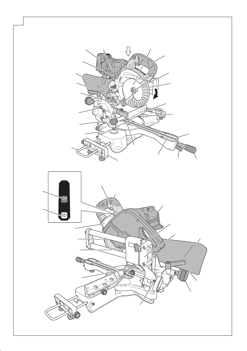
Handle
1
Saw blade
2
Motor head
3
Motor
4
Battery
5
LED light (left)
6
Locking pin
7
Hinge
8
Laser marker
9
Indicator (For right bevel scale)
0
Vise assembly
!
Fence (B)
@
Holder
#
Sub table assembly
$
Guard
%
Table Insert
^
Lever
&
Side handle
*
Turntable
(
Miter scale indicator
)
(For degrees scale)
Fence (A)
q
Rotation direction
w
Lower guard
e
Left hex. 7 mm socket bolt
r
Trigger switch
t
Switch lock
y
Switch panel
u
Switch (For laser marker)
i
Switch (For LED light)
o
Nameplate
p
Spindle Lock
a
LED light (right)
s
Adjuster (For laser marker)
d
Indicator (For left bevel scale)
f
Knob
g
Clamp lever
h
Dust bag
j
Holder (A)
k
Slide securing wing bolt
l
Terminals
;
Side of the side handle
z
Base
x
Work bench
c
8 mm bolt
v
8 mm nut
b
25 mm thick bench
n
Set screw
m
Rise
,
Fall
.
Set pin (A)
/
8 mm set Screw (Stopper for 0°)
¡
6 mm bolt (A)
™
(Stopper for left 45° bevel angle)
Tighten
£
Loosen
¢
Press at 0° (right angle)
∞
6 mm bolt (B)
§
(Stopper for right 45° bevel angle)
Pull out when slanted to the right
¶
8 mm depth adjustment bolt
•
Latch
ª
Battery level indicator switch
º
Battery level indicator lamp
⁄
Warning sign
¤
Line
‹
Workpiece
›
Vise plate
fi
Knob
fl
Screw holder
‡
6 mm wing bolt
°
Vise shaft
·
V-groove
‚
Top of the fence
Œ
6 mm knob bolt
„
Groove
´
Fence surface
‰
5 mm machine screw
ˇ
Right angle cutting
Á
Left bevel angle cutting
¨
Right bevel angle cutting
î
6 mm knob bolt
Ø
Sub fence (B)
∏
Sub fence (A)
Å
6 mm knob bolt
Í
Groove
Î
Laser line
Ï
Marking (pre-marked)
˝
Auxiliary board
Ó
Width
Ô
6 mm fl at head screw
6 mm nut
Ò
Stopper (B)
Ú
Stopper holder
¸
6 mm depth adjustment bolt
˛
Lower the motor head
Ç
Spacer (D)
◊
Miter scale (Degrees scale)
ı
Miter scale indicator (For gradient
˜
scale)
Miter scale (Gradient scale)
Â
6 mm hex. socket bolt
¯
6 mm knob Bolt
˘
Steel square
¿
Set screw
101
Crown molding
102
Upper surface of crown molding
103
Lower surface of crown molding
104
Ceiling
105
106
Wall
107
Inside corner
108
109
Outside corner
110
111
Gear Case
112
Duct
113
Dust extractor
114
Hose (id 38 mm × 3 m long)
Adapter
115
(Dust extractor's standard
accessory)
116
Joint (Optional accessory)
Dust collection adapter
117
(Optional accessory)
118
Hose band (Optional accessory)
119
Washer (B)
120
Washer (A)
121
5 mm hex. bar wrench
122
Piece of wood
123
Carry handle
124
Base grip
125
Air gun
15
Page 16

GENERAL POWER TOOL SAFETY
WARNINGS
WARNING
Read all safety warnings, instructions, illustrations and
specifi cations provided with this power tool.
Failure to follow all instructions listed below may result in
electric shock, fi re and/or serious injury.
Save all warnings and instructions for future reference.
The term “power tool” in the warnings refers to your mainsoperated (corded) power tool or battery-operated (cordless)
power tool.
1) Work area safety
a) Keep work area clean and well lit.
Cluttered or dark areas invite accidents.
b) Do not operate power tools in explosive
atmospheres, such as in the presence of
fl ammable liquids, gases or dust.
Power tools create sparks which may ignite the dust
or fumes.
c) Keep children and bystanders away while
operating a power tool.
Distractions can cause you to lose control.
2) Electrical safety
a) Power tool plugs must match the outlet. Never
modify the plug in any way. Do not use any
adapter plugs with earthed (grounded) power
tools.
Unmodifi ed plugs and matching outlets will reduce
risk of electric shock.
b) Avoid body contact with earthed or grounded
surfaces, such as pipes, radiators, ranges and
refrigerators.
There is an increased risk of electric shock if your
body is earthed or grounded.
c) Do not expose power tools to rain or wet
conditions.
Water entering a power tool will increase the risk of
electric shock.
d) Do not abuse the cord. Never use the cord for
carrying, pulling or unplugging the power tool.
Keep cord away from heat, oil, sharp edges or
moving parts.
Damaged or entangled cords increase the risk of
electric shock.
e) When operating a power tool outdoors, use an
extension cord suitable for outdoor use.
Use of a cord suitable for outdoor use reduces the
risk of electric shock.
f) If operating a power tool in a damp location
is unavoidable, use a residual current device
(RCD) protected supply.
Use of an RCD reduces the risk of electric shock.
3) Personal safety
a) Stay alert, watch what you are doing and use
common sense when operating a power tool.
Do not use a power tool while you are tired
or under the infl uence of drugs, alcohol or
medication.
A moment of inattention while operating power tools
may result in serious personal injury.
b) Use personal protective equipment. Always
wear eye protection.
Protective equipment such as a dust mask, non-skid
safety shoes, hard hat or hearing protection used for
appropriate conditions will reduce personal injuries.
c) Prevent unintentional starting. Ensure the
switch is in the off -position before connecting
to power source and/or battery pack, picking up
or carrying the tool.
Carrying power tools with your fi nger on the switch
or energising power tools that have the switch on
invites accidents.
d) Remove any adjusting key or wrench before
turning the power tool on.
A wrench or a key left attached to a rotating part of
the power tool may result in personal injury.
e) Do not overreach. Keep proper footing and
balance at all times.
This enables better control of the power tool in
unexpected situations.
f) Dress properly. Do not wear loose clothing or
jewellery. Keep your hair and clothing away
from moving parts.
Loose clothes, jewellery or long hair can be caught in
moving parts.
g) If devices are provided for the connection of
dust extraction and collection facilities, ensure
these are connected and properly used.
Use of dust collection can reduce dust-related
hazards.
h) Do not let familiarity gained from frequent use
of tools allow you to become complacent and
ignore tool safety principles.
A careless action can cause severe injury within a
fraction of a second.
4) Power tool use and care
a) Do not force the power tool. Use the correct
power tool for your application.
The correct power tool will do the job better and safer
at the rate for which it was designed.
b) Do not use the power tool if the switch does not
turn it on and off
Any power tool that cannot be controlled with the
switch is dangerous and must be repaired.
c) Disconnect the plug from the power source and/
or remove the battery pack, if detachable, from
the power tool before making any adjustments,
changing accessories, or storing power tools.
Such preventive safety measures reduce the risk of
starting the power tool accidentally.
d) Store idle power tools out of the reach of
children and do not allow persons unfamiliar
with the power tool or these instructions to
operate the power tool.
Power tools are dangerous in the hands of untrained
users.
e) Maintain power tools and accessories. Check
for misalignment or binding of moving parts,
breakage of parts and any other condition
that may aff ect the power toolʼs operation. If
damaged, have the power tool repaired before
use.
Many accidents are caused by poorly maintained
power tools.
f) Keep cutting tools sharp and clean.
Properly maintained cutting tools with sharp cutting
edges are less likely to bind and are easier to control.
g) Use the power tool, accessories and tool bits
etc. in accordance with these instructions,
taking into account the working conditions and
the work to be performed.
Use of the power tool for operations diff erent from
those intended could result in a hazardous situation.
.
16
Page 17

h) Keep handles and grasping surfaces dry, clean
and free from oil and grease.
Slippery handles and grasping surfaces do not
allow for safe handling and control of the tool in
unexpected situations.
5) Battery tool use and care
a) Recharge only with the charger specifi ed by the
manufacturer.
A charger that is suitable for one type of battery pack
may create a risk of fi re when used with another
battery pack.
b) Use power tools only with specifi cally
designated battery packs.
Use of any other battery packs may create a risk of
injury and fi re.
c) When battery pack is not in use, keep it away
from other metal objects, like paper clips, coins,
keys, nails, screws or other small metal objects,
that can make a connection from one terminal to
another.
Shorting the battery terminals together may cause
burns or a fi re.
d) Under abusive conditions, liquid may be ejected
from the battery; avoid contact. If contact
accidentally occurs, fl ush with water. If liquid
contacts eyes, additionally seek medical help.
Liquid ejected from the battery may cause irritation or
burns.
e) Do not use a battery pack or tool that is damaged
or modifi ed.
Damaged or modifi ed batteries may exhibit
unpredictable behaviour resulting in fi re, explosion
or risk of injury.
f) Do not expose a battery pack or tool to fi re or
excessive temperature.
Exposure to fi re or temperature above 130°C may
cause explosion.
g) Follow all charging instructions and do not
charge the battery pack or tool outside the
temperature range specifi ed in the instructions.
Charging improperly or at temperatures outside
the specifi ed range may damage the battery and
increase the risk of fi re.
6) Service
a) Have your power tool serviced by a qualifi ed
repair person using only identical replacement
parts.
This will ensure that the safety of the power tool is
maintained.
b) Never service damaged battery packs.
Service of battery packs should only be performed
by the manufacturer or authorized service providers.
PRECAUTION
Keep children and infi rm persons away.
When not in use, tools should be stored out of reach of
children and infi rm persons.
SAFETY INSTRUCTIONS FOR MITER
SAW
a) Miter saws are intended to cut wood or wood-like
products, they cannot be used with abrasive cutoff wheels for cutting ferrous material such as bars,
rods, studs, etc.
Abrasive dust causes moving parts such as the lower
guard to jam. Sparks from abrasive cutting will burn the
lower guard, the kerf insert and other plastic parts.
b) Use clamps to support the workpiece whenever
possible. If supporting the workpiece by hand, you
must always keep your hand at least 100 mm from
either side of the saw blade. Do not use this saw to
cut pieces that are too small to be securely clamped
or held by hand.
If your hand is placed too close to the saw blade, there is
an increased risk of injury from blade contact.
c) The workpiece must be stationary and clamped or
held against both the fence and the table. Do not
feed the workpiece into the blade or cut "freehand"
in any way.
Unrestrained or moving workpieces could be thrown at
high speeds, causing injury.
d) Push the saw through the workpiece. Do not pull
the saw through the workpiece. To make a cut, raise
the saw head and pull it out over the workpiece
without cutting, start the motor, press the saw head
down and push the saw through the workpiece.
Cutting on the pull stroke is likely to cause the saw blade
to climb on top of the workpiece and violently throw the
blade assembly towards the operator.
e) Never cross your hand over the intended line of
cutting either in front or behind the saw blade.
Supporting the workpiece “cross handed” i.e. holding
the workpiece to the right of the saw blade with your left
hand or vice versa is very dangerous.
f) Do not reach behind the fence with either hand
closer than 100 mm from either side of the saw
blade, to remove wood scraps, or for any other
reason while the blade is spinning.
The proximity of the spinning saw blade to your hand
may not be obvious and you may be seriously injured.
g) Inspect your workpiece before cutting. If the
workpiece is bowed or warped, clamp it with the
outside bowed face toward the fence. Always make
certain that there is no gap between the workpiece,
fence and table along the line of the cut.
Bent or warped workpieces can twist or shift and may
cause binding on tile spinning saw blade while cutting.
There should be no nails or foreign objects in the
workpiece.
h) Do not use the saw until the table is clear of all
tools, wood scraps, etc., except for the workpiece.
Small debris or loose pieces of wood or other objects
that contact the revolving blade can be thrown with high
speed.
i) Cut only one workpiece at a time.
Stacked multiple workpieces cannot be adequately
clamped or braced and may bind on the blade or shift
during cutting.
j) Ensure the miter saw is mounted or placed on a
level, fi rm work surface before use.
A level and fi rm work surface reduces the risk of the miter
saw becoming unstable.
k) Plan your work. Every time you change the bevel or
miter angle setting, make sure the adjustable fence
is set correctly to support the workpiece and will
not interfere with the blade or the guarding system.
Without turning the tool “ON” and with no workpiece
on the table, move the saw blade through a complete
simulated cut to assure there will be no interference or
danger of cutting the fence.
I) Provide adequate support such as table extensions,
saw horses, etc. for a workpiece that is wider or
longer than the table top.
Workpieces longer or wider than the miter saw table
can tip if not securely supported. If the cut-off piece or
workpiece tips, it can lift the lower guard or be thrown by
the spinning blade.
17
Page 18

m) Do not use another person as a substitute for a
table extension or as additional support.
Unstable support for the workpiece can cause the
blade to bind or the workpiece to shift during the cutting
operation pulling you and the helper into the spinning
blade.
n) The cut-off piece must not be jammed or pressed
by any means against the spinning saw blade.
If confi ned, i.e. using length stops, the cut-off piece could
get wedged against the blade and thrown violently.
o) Always use a clamp or a fi xture designed to properly
support round material such as rods or tubing.
Rods have a tendency to roll while being cut, causing the
blade to "bite" and pull the work with your hand into the
blade.
p) Let the blade reach full speed before contacting the
workpiece.
This will reduce the risk of the workpiece being thrown.
q) If the workpiece or blade becomes jammed, turn the
miter saw off . Wait for all moving parts to stop and
disconnect the plug from the power source and/
or remove the battery pack. Then work to free the
jammed material.
Continued sawing with a jammed workpiece could cause
lass of control or damage to the miter saw.
r) After fi nishing the cut, release the switch, hold
the saw head down and wait for the blade to stop
before removing the cut-off piece.
Reaching with your hand near the coasting blade is
dangerous.
s) Hold the handle fi rmly when making an incomplete
cut or when releasing the switch before the saw
head is completely in the down position.
The braking action of the saw may cause the saw head
to be suddenly pulled downward, causing a risk of injury.
PRECAUTIONS ON USING SLIDE
COMPOUND MITER SAW
1. Keep the fl oor area around the machine level. Well
maintained and free of loose materials e.g. chips and
cut-off s.
2. Provide adequate general or localized lighting.
3. Do not use power tools for applications other than those
specifi ed in the handling instructions.
4. Repairing must be done only by authorized service
facility. Manufacturer is not responsible for any damages
and injuries due to the repair by the unauthorized
persons as well as the mishandling of the tool.
5. To ensure the designed operational integrity of power
tools, do not remove installed covers or screws.
6. Do not touch movable parts or accessories unless the
power source has been disconnected.
7. Use your tool at lower input than specifi ed on the
nameplate; otherwise, the fi nish may be spoiled and
working effi ciency reduced due to motor overload.
8. Do not wipe plastic parts with solvent. Solvents such as
gasoline, thinner, benzine, carbon tetrachloride, alcohol,
may damage and crack plastic parts. Do not wipe them
with such solvent. Clean plastic parts with a soft cloth
lightly dampened with soapy water.
9. Use only original HiKOKI replacement parts.
10. The exploded assembly drawing on this handling
instructions should be used only for authorized service
facility.
11. Never cut ferrous metals or masonry.
12. Adequate general or localized lighting is provided.
Stock and fi nished workpieces are located close to the
operators normal working position.
13. Wear suitable personal protective equipment when
necessary, this could include:
Hearing protection to reduce the risk of induced hearing
loss.
Eye protection to reduce the risk of injuring an eye.
Respiratory protection to reduce the risk of inhalation of
harmful dust.
Gloves for handling saw blades (saw blades shall be
carried in a holder wherever practicable) and rough
material.
14. The operator is adequately trained in the use, adjustment
and operation of the machine.
15. Refrain from removing any cut-off s or other parts of the
workpiece from the cutting area whilst the machine is
running and the saw head is not in the rest position.
16. Never use the slide compound miter saw with its lower
guard locked in the open position.
17. Ensure that the lower guard moves smoothly.
18. Do not use the saw without guards in position, in good
working order and properly maintained.
19. Use correctly sharpened saw blades. Observe the
maximum speed marked on the saw blade.
20. Do not use saw blades which are damaged or deformed.
21. Do not use saw blades manufactured from high speed
steel.
22. Use only saw blades recommended by HiKOKI.
Use of saw blade comply with EN847-1.
23. The saw blades should be 185 mm external diameter.
24. Select the correct saw blade for the material to be cut.
25. Never operate the slide compound miter saw with the
saw blade turned upward or to the side.
26. Ensure that the workpiece is free of foreign matter such
as nails.
27. Replace the table insert when worn.
28. Do not use the saw to cut other than aluminium, wood or
similar materials.
29. Do not use the saw to cut other materials than those
recommended by the manufacturer.
30. Blade replacement procedure, including the method for
repositioning and a warning that this must be carried out
correctly.
31. Connect the slide compound miter saw to a dust
collecting device when sawing wood.
32. Take care when slotting.
33. Start cutting only after motor revolution reaches
maximum speed.
34. Promptly cut OFF the switch when abnormality observed.
35. Shut off power and wait for saw blade to stop before
servicing or adjusting tool.
36. During a miter or bevel cut the blade should not be lifted
until it has stopped rotation completely.
37. During slide cutting operation, the saw must be pushed
and slided away from the operator.
38. Take all the possibility of residual risks in cutting
operation into your consideration, such as the laser
radiation to your eyes, the inadvertent access to moving
parts on slide mechanical parts on machine and so on.
39. Ensure before each cut that the machine is stable.
Use only saw blades whose maximum permitted speed
is higher than the no-load speed of the power tool.
Do not replace the laser with a diff erent type.
40. Do not stand in a line with the saw blade In front of the
machine. Always stand aside of the saw blade. This
protects your body against possible kickback. Keep
hands, fi ngers and arms away from the rotating saw blade.
Do not cross your arms when operating the tool arm.
41. If the saw blade should become jammed, switch the
machine off and hold the workpiece until the saw blade
comes to a complete stop. To prevent kickback, the
workpiece may not be moved until after the machine has
come to a complete stop.
Correct the cause for the jamming of the saw blade
before restarting the machine.
18
Page 19

ADDITIONAL SAFETY WARNINGS
1. Do not allow foreign matter to enter the hole for
connecting the rechargeable battery.
2. Never disassemble the rechargeable battery and
charger.
3. Never short-circuit the rechargeable battery.
Shortcircuiting the battery will cause a great electric
current and overheat. It results in burn or damage to the
battery.
4. Do not dispose of the battery in fi re. If the battery is burnt,
it may explode.
5. When using this unit continuously, the unit may overheat,
leading to damage in the motor and switch. Please leave
it without using it for approximately 15 minutes.
6. Do not insert object into the air ventilation slots of the
charger. Inserting metal objects or infl ammables into the
charger air ventilation slots will result in electrical shock
hazard or damaged charger.
7. Using an exhausted battery will damage the charger.
8. Bring the battery to the shop from which it was purchased
as soon as the post-charging battery life becomes too
short for practical use. Do not dispose of the exhausted
battery.
9. Do not use the product if the tool or the battery terminals
(battery mount) are deformed.
Installing the battery could cause a short circuit that
could result in smoke emission or ignition.
10. Keep the tool’s terminals (battery mount) free of swarf
and dust.
○ Prior to use, make sure that swarf and dust have not
collected in the area of the terminals.
○ During use, try to avoid swarf or dust on the tool from
falling on the battery.
○ When suspending operation or after use, do not leave
the tool in an area where it may be exposed to falling
swarf or dust.
Doing so could cause a short circuit that could result in
smoke emission or ignition.
11. Always use the tool and battery at temperatures between
0°C and 40°C.
CAUTION ON LITHIUM-ION BATTERY
To extend the lifetime, the lithium-ion battery equips with the
protection function to stop the output.
In the cases of 1 to 3 described below, when using this
product, even if you are pulling the switch, the motor may
stop. This is not the trouble but the result of protection
function.
1. When the battery power remaining runs out, the motor
stops.
In such a case, charge it up immediately.
2. If the tool is overloaded, the motor may stop. In this
case, release the switch of tool and eliminate causes of
overloading. After that, you can use it again.
3. If the battery is overheated under overload work, the
battery power may stop.
In this case, stop using the battery and let the battery
cool. After that, you can use it again.
Furthermore, please heed the following warning and caution.
WARNING
In order to prevent any battery leakage, heat generation,
smoke emission, explosion and ignition beforehand, please
be sure to heed the following precautions.
1. Make sure that swarf and dust do not collect on the
battery.
○ During work make sure that swarf and dust do not fall on
the battery.
○ Make sure that any swarf and dust falling on the power
tool during work do not collect on the battery.
19
○ Do not store an unused battery in a location exposed to
swarf and dust.
○ Before storing a battery, remove any swarf and dust that
may adhere to it and do not store it together with metal
parts (screws, nails, etc.).
2. Do not pierce battery with a sharp object such as a
nail, strike with a hammer, step on, throw or subject the
battery to severe physical shock.
3. Do not use an apparently damaged or deformed battery.
4. Do not use the battery in reverse polarity.
5. Do not connect directly to an electrical outlets or car
cigarette lighter sockets.
6. Do not use the battery for a purpose other than those
specifi ed.
7. If the battery charging fails to complete even when a
specifi ed recharging time has elapsed, immediately stop
further recharging.
8. Do not put or subject the battery to high temperatures or
high pressure such as into a microwave oven, dryer, or
high pressure container.
9. Keep away from fi re immediately when leakage or foul
odor are detected.
10. Do not use in a location where strong static electricity
generates.
11. If there is battery leakage, foul odor, heat generated,
discolored or deformed, or in any way appears abnormal
during use, recharging or storage, immediately remove it
from the equipment or battery charger, and stop use.
12. Do not immerse the battery or allow any fl uids to fl ow
inside. Conductive liquid ingress, such as water, can
cause damage resulting in fi re or explosion. Store your
battery in a cool, dry place, away from combustible and
fl ammable items. Corrosive gas atmospheres must be
avoided.
CAUTION
1. If liquid leaking from the battery gets into your eyes,
do not rub your eyes and wash them well with fresh
clean water such as tap water and contact a doctor
immediately.
If left untreated, the liquid may cause eye-problems.
2. If liquid leaks onto your skin or clothes, wash well with
clean water such as tap water immediately.
There is a possibility that this can cause skin irritation.
3. If you fi nd rust, foul odor, overheating, discolor,
deformation, and/or other irregularities when using the
battery for the fi rst time, do not use and return it to your
supplier or vendor.
WARNING
If a conductive foreign matter enters in the terminal of lithium
ion battery, the battery may be shorted, causing fi re. When
storing the lithium ion battery, obey surely the rules of
following contents.
○ Do not place conductive debris, nail and wires such as
iron wire and copper wire in the storage case.
○ To prevent shorting from occurring, load the battery in
the tool or insert securely the battery cover for storing
until the ventilator is not seen.
Page 20

REGARDING LITHIUM-ION BATTERY
TRANSPORTATION
When transporting a lithium-ion battery, please observe the
following precautions.
WARNING
Notify the transporting company that a package contains a
lithium-ion battery, inform the company of its power output
and follow the instructions of the transportation company
when arranging transport.
○ Lithium-ion batteries that exceed a power output of
100Wh are considered to be in the freight classifi cation
of Dangerous Goods and will require special application
procedures.
○ For transportation abroad, you must comply with
international law and the rules and regulations of the
destination country.
○ If the BSL36B18 (sold separately) is installed in the
power tool, the power output will exceed 100 Wh and
the unit will be classifi ed as Dangerous Goods for freight
classifi cation.
SYMBOLS
WARNING
The following show symbols used for the machine.
Be sure that you understand their meaning before
use.
C3607DRA:
Cordless Slide Compound Miter Saw
To reduce the risk of injury, user must read
instruction manual.
Always wear eye protection.
Always wear hearing protection.
Do not stare at operating lamp.
Power Output
Wh
2 to 3 digit number
USB DEVICE CONNECTION
PRECAUTIONS (ONLY WITH
UC18YSL3 CHARGER)
When an unexpected problem occurs, the data in a USB
device connected to this product may be corrupted or lost.
Always make sure to back up any data contained in the USB
device prior to use with this product.
Please be aware that our company accepts absolutely no
responsibility for any data stored in a USB device that is
corrupted or lost, nor for any damage that may occur to a
connected device.
WARNING
○ Prior to use, check the connecting USB cable for any
defect or damage.
Using a defective or damaged USB cable can cause
smoke emission or ignition.
○ When the product is not being used, cover the USB port
with the rubber cover.
Buildup of dust etc. in the USB port can cause smoke
emission or ignition.
NOTE
○ There may be an occasional pause during USB
recharging.
○ When a USB device is not being charged, remove the
USB device from the charger.
Failure to do so may not only reduce the battery life
of a USB device, but may also result in unexpected
accidents.
○ It may not be possible to charge some USB devices,
depending on the type of device.
Switching ON
Switching OFF
Battery
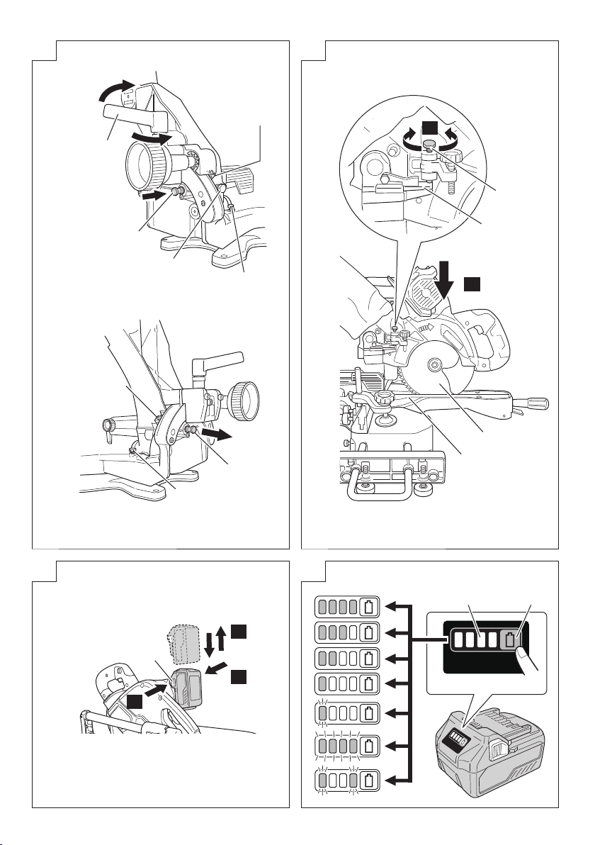
Lights ;
The battery remaining power is over 75%
Lights ;
The battery remaining power is 50% – 75%.
Lights ;
The battery remaining power is 25% – 50%.
Lights ;
The battery remaining power is less than 25%
Blinks ;
The battery remaining power is nearly empty.
Recharge the battery soonest possible.
Blinks ;
Output suspended due to high temperature.
Remove the battery from the tool and allow it to
fully cool down.
Blinks ;
Output suspended due to failure or malfunction.
The problem may be the battery so please
contact your dealer.
NOTE
To prevent the battery power consumption caused by
forgetting to turn off the LED light, the light goes off
automatically in about 2 minutes.
20
Page 21

SPECIFICATIONS
1. Power tool
0° 58 mm × 310 mm
Miter 45° 58 mm × 218 mm
Max. Cutting
Capacity
Height × Width
Saw Blade Dimensions (oD × iD × Thickness) 185 mm × 20 mm × 2 mm
Miter Cutting Angle Right 0° – 57°, Left 0° – 45°
Bevel Cutting Angle Right 0° – 45°, Left 0° – 45°
Compound Cutting Angle
Voltage 36 V
No-Load Speed 4000 /min
Machine Dimensions (Width × Depth × Height) 830 mm × 780 mm × 484 mm
Battery available for this tool* Multi volt battery
Weight** 15.4 kg
Laser Marker
Bevel
Compound
Bevel (Left) 45° + Miter (Left) 45° 39 mm × 218 mm
Bevel (Left) 45° + Miter (Right) 45° 39 mm × 218 mm
Bevel (Right) 45° + Miter (Right) 45° 16 mm × 218 mm
Bevel (Right) 45° + Miter (Left) 31° 16 mm × 258 mm
Left 45° 39 mm × 310 mm
Right 45° 16 mm × 310 mm
Bevel (Left) 0° – 45° Miter (Left) 0° – 45°, (Right) 0° – 45°
Bevel (Right) 0° – 45° Miter (Right) 0° – 45°, (Left) 0° – 31°
Maximum output
(Iambda) 650 nm
Laser medium Laser Diode
Po<0.4 mW Class 1M Laser Product
* Existing batteries (BSL3660/3620/3626, BSL18....
series, etc.) cannot be used with this tool.
** According to EPTA-Procedure 01/2014
Depending on attached battery.
The heaviest weight is measured with BSL36B18 (sold
separately).
NOTE
Due to HiKOKI’s continuing program of research and
development, the specifi cations herein are subject to
change without prior notice.
2. Battery
Model BSL36A18 BSL36B18
Voltage 36 V / 18 V (Automatic Switching*)
batteries
4.0 Ah / 8.0 Ah
(Automatic
Switching*)
Battery capacity
Available cordless
products**
Available charger
* The tool itself will automatically switch over.
** Please see our general catalogue for details.
2.5 Ah / 5.0 Ah
(Automatic
Switching*)
Multi volt series, 18 V product
Sliding charger for lithium ion
STANDARD ACCESSORIES
In addition to the main unit (1 unit), the package contains the
accessories listed on page 31.
Standard accessories are subject to change without notice.
APPLICATION
Cutting various types of wood.
CHARGING
Before using the power tool, charge the battery as follows.
1. Connect the charger’s power cord to the receptacle.
When connecting the plug of the charger to a receptacle,
the charge indicator lamp will blink in red (At 1- second
intervals).
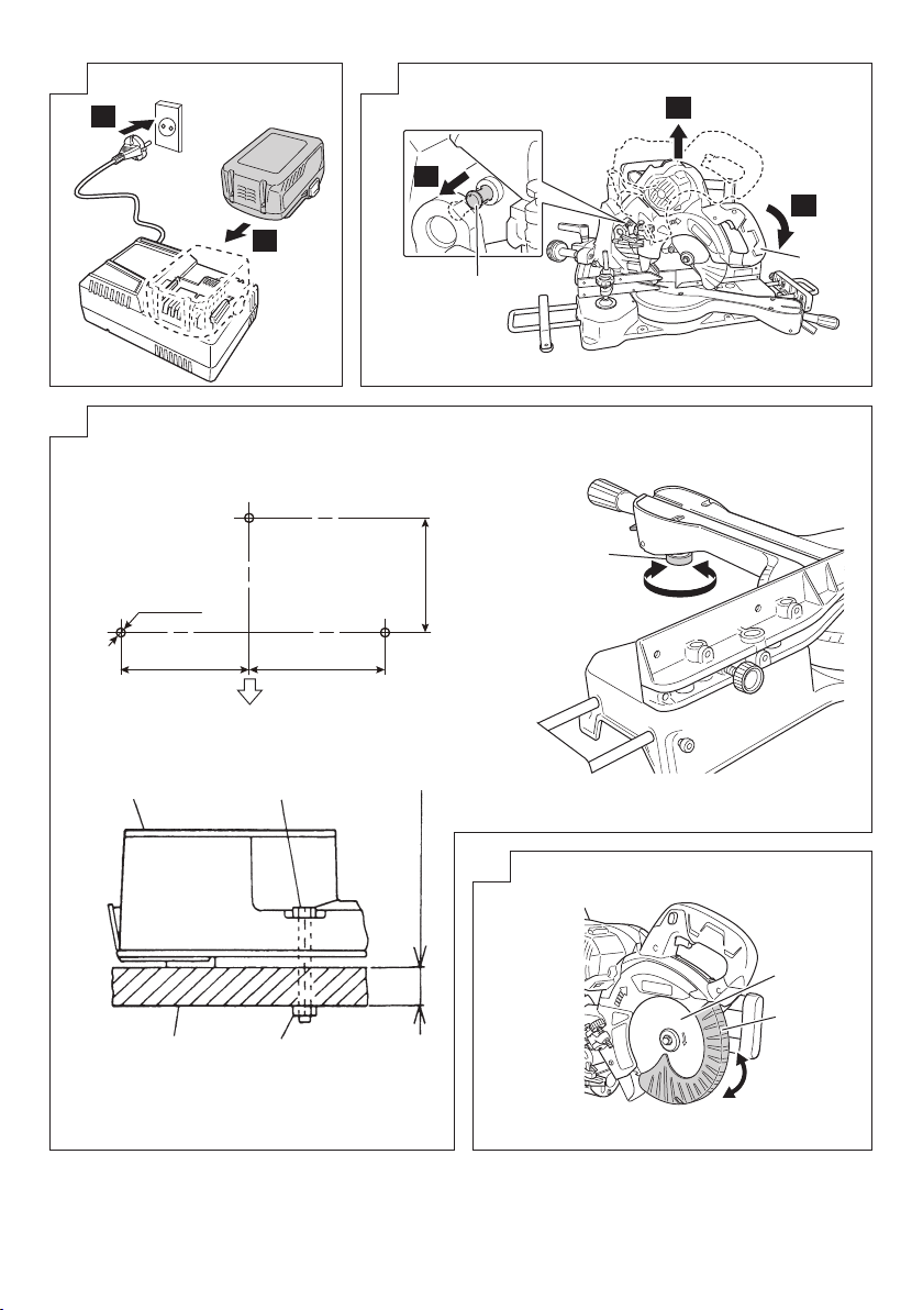
2. Insert the battery into the charger.
Firmly insert the battery into the charger as shown in
Fig. 2 (on page 3).
3. Charging
When inserting a battery in the charger, the charge
indicator lamp will blink in blue.
When the battery becomes fully recharged, the charge
indicator lamp will light up in green. (See Table 1)
(1) Charge indicator lamp indication
The indications of the charge indicator lamp will be as
shown in Table 1, according to the condition of the
charger or the rechargeable battery.
21
Page 22

Table 1
Indications of the charge indicator lamp
Before
charging
While
charging
Charge
indicator
lamp
(RED /
BLUE /
GREEN /
PURPLE)
(2) Regarding the temperatures and charging time of the rechargeable battery
The temperatures and charging time will become as shown in Table 2.
Battery
USB
NOTE
The recharging time may vary according to the ambient temperature and power source voltage.
Charging
complete
Overheat
standby
Charging
impossible
Type of battery Li-ion
Temperatures at which the
battery can be recharged
Charging voltage V 14.4 18
Charging time,
approx. (At 20°C)
Charging voltage V 5
Charging current A 2
Blinks
(RED)
Blinks
(BLUE)
Blinks
(BLUE)
Lights
(BLUE)
Lights
(GREEN)
Blinks
(RED)
Flickers
(PURPLE)
Charger
Lights for 0.5 seconds. Does not light for
0.5 seconds. (off for 0.5 seconds)
Lights for 0.5 seconds. Does not light for
1 second. (off for 1 second)
Lights for 1 second. Does not light
for 0.5 seconds. (off for 0.5 seconds)
Lights continuously
Lights continuously
(Continuous buzzer sound: about 6
seconds)
Lights for 0.3 seconds. Does not light for
0.3 seconds. (off for 0.3 seconds)
Lights for 0.1 seconds. Does not light for
0.1 seconds. (off for 0.1 seconds)
(Intermittent buzzer sound: about 2
seconds)
Table 2
BSL14xx series BSL18xx series
(4 cells) (8 cells) (5 cells) (10 cells) (10 cells)
BSL1415S : 15
BSL1415
:
15
min.
BSL1415X
BSL1420
BSL1425
BSL1430C
:
:
:
:
15
20
25
30
BSL1430
BSL1440
BSL1450
BSL1460
:
:
:
:
20
26
32
38
Plugged into power source
Battery capacity at less than 50%
Battery capacity at less than 80%
Battery capacity at more than 80%
Battery overheated. Unable to
charge. (Charging will commence
when battery cools)
Malfunction in the battery or the
charger
UC18YSL3
0°C – 50°C
BSL1815S : 15
BSL1815 : 15
BSL1815X : 15
BSL1820 : 20
BSL1825 : 25
BSL1830C : 30
BSL1830 : 20
BSL1840 : 26
BSL1850 : 32
BSL1860 : 38
Multi volt
series
BSL36A18 : 32
BSL36B18 : 52
4. Disconnect the charger’s power cord from the
receptacle.
5. Hold the charger fi rmly and pull out the battery.
NOTE
Be sure to pull out the battery from the charger after use,
and then keep it.
Regarding electric discharge in case of new batteries,
etc.
As the internal chemical substance of new batteries and
batteries that have not been used for an extended period
is not activated, the electric discharge might be low when
using them the fi rst and second time. This is a temporary
phenomenon, and normal time required for recharging
will be restored by recharging the batteries 2 – 3 times.
22
Page 23

How to make the batteries perform longer.
(1) Recharge the batteries before they become completely
exhausted.
When you feel that the power of the tool becomes
weaker, stop using the tool and recharge its battery. If
you continue to use the tool and exhaust the electric
current, the battery may be damaged and its life will
become shorter.
(2) Avoid recharging at high temperatures.
A rechargeable battery will be hot immediately after
use. If such a battery is recharged immediately after
use, its internal chemical substance will deteriorate, and
the battery life will be shortened. Leave the battery and
recharge it after it has cooled for a while.
CAUTION
○ If the battery is charged while it is heated because
it has been left for a long time in a location subject to
direct sunlight or because the battery has just been
used, the charge indicator lamp of the charger lights
for 0.3 seconds, does not light for 0.3 seconds (off for
0.3 seconds). In such a case, fi rst let the battery cool,
then start charging.
○ When the charge indicator lamp fl ickers (at 0.2-second
intervals), check for and take out any foreign objects in
the charger’s battery connector. If there are no foreign
objects, it is probable that the battery or charger is
malfunctioning. Take it to your authorized Service Center.
○ Since the built-in micro computer takes about
3 seconds to confi rm that the battery being charged with
UC18YSL3 is taken out, wait for a minimum of 3 seconds
before reinserting it to continue charging. If the battery
is reinserted within 3 seconds, the battery may not be
properly charged.
PRIOR TO OPERATION
CAUTION
Pull out battery before carrying out any adjustment,
servicing or maintenance.
When fi nished with a job, pull out the battery.
1. Power source
Ensure that the power source to be utilized conforms
to the power requirements specifi ed on the product
nameplate.
2. Power switch
Ensure that the switch is in the OFF position. If the battery
installed to power tool while the switch is in the ON
position, the power tool will start operating immediately,
which could cause a serious accident.
3. Remove all packing materials attached or
connected to the tool before attempting to operate
it.
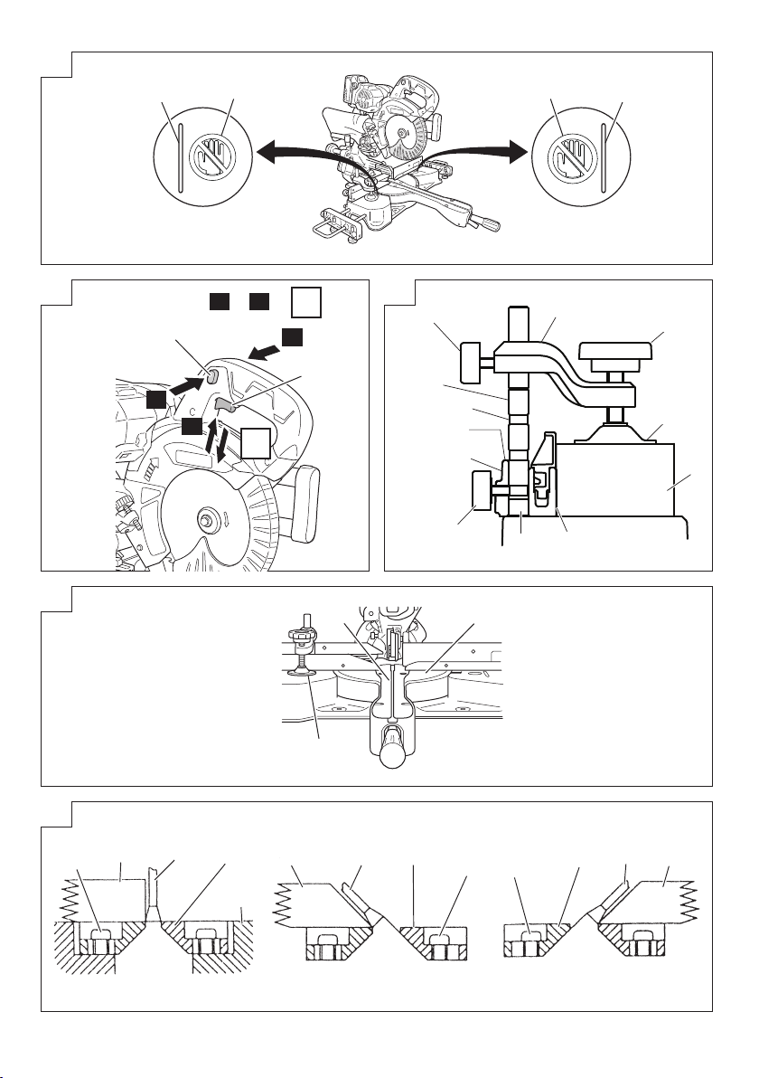
4. Releasing the locking pin (Fig. 3)
When the power tool is prepared for shipping, its main
parts are secured by a locking pin.
Move the handle slightly so that the locking pin can be
disengaged.
During transport, lock the locking pin into the gear case.
5. Installing the sub tables (Standard accessory)
(Fig. 27)
The sub tables help keep longer workpieces stable and
in place during the cutting operation.
(1) Loosen the 6 mm hex. socket bolts with 5 mm hex. bar
wrench (standard accessory). Insert the holder into the
base.
(2) Use a steel square for aligning the upper surface of the
sub tables with the base surface.
Turn the set screws, and adjust the height of the sub
tables.
(3) After adjustment, fi rmly tighten the 6 mm knob bolts and
fasten the holder with the 6 mm hex. socket bolts. If the
length of set screws is insuffi cient, spread a thin plate
beneath.
CAUTION
○ When transporting or carrying the tool, do not grasp the
sub tables or holders.
○ There is the danger of the sub tables or holders slipping
out of the base. Grasp the handle instead of the sub
tables or holders.
6. Installing the side handle (Fig. 1)
Install the side handle that came enclosed with this unit.
7. Attach the dust bag to the main unit (Fig. 1)
8. Installation (Fig. 4)
Ensure that the machine is always fi xed to bench.
Attach the power tool to a level, horizontal work bench.
Select 8 mm diameter bolts suitable in length for the
thickness of the work bench.
Bolt length should be at least 40 mm plus the thickness
of the work bench.
For example, use 8 mm × 65 mm bolts for a 25 mm thick
work bench.
Turn the setscrew left or right to adjust the setscrew for
light contact with the fl oor.
9. Check to see that the lower guard operates
smoothly (Fig. 5)
The protective cover prevents physical contact with the
saw blade.
Make sure that the saw blade is covered and moves
smoothly.
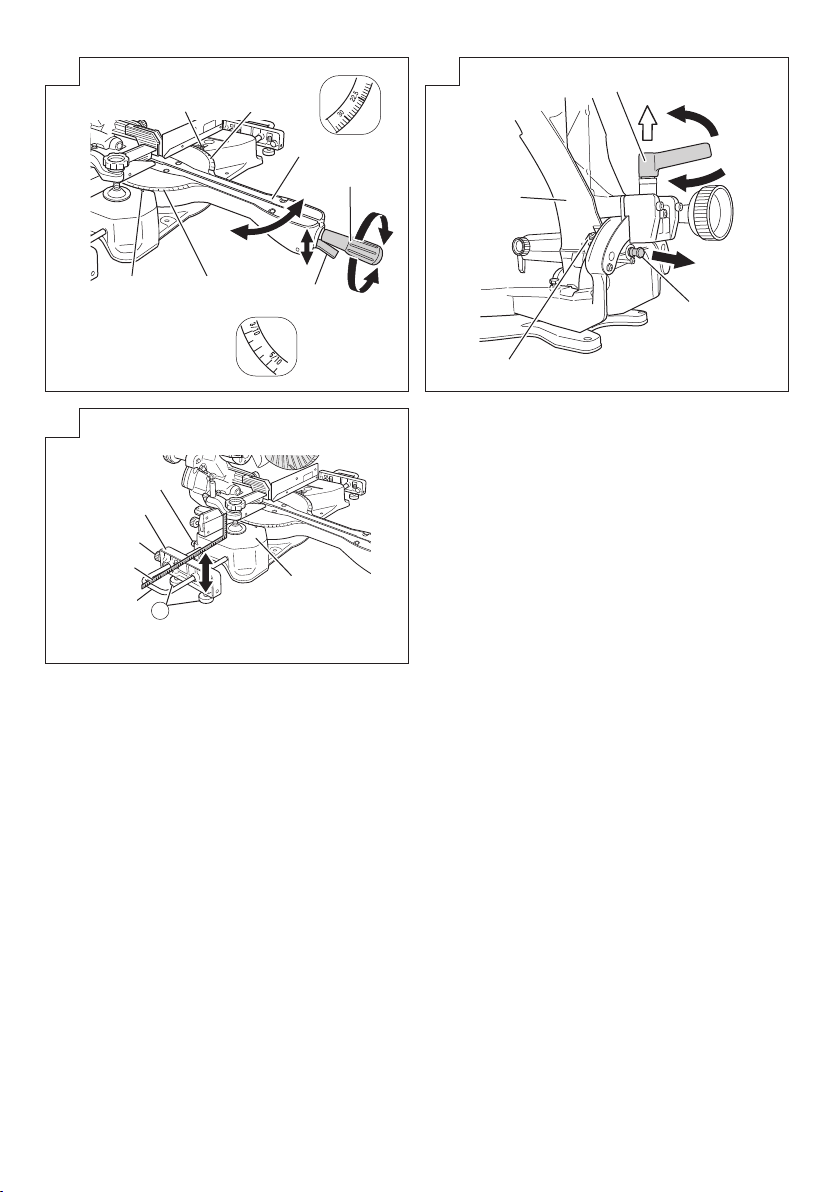
10. Oblique angle
Before the power tool is shipped from the factory, it is
adjusted for 0°, right angle, left 45° bevel cutting angle
and right 45° bevel cutting angle with the 8 mm set
screw, 6 mm bolt (A) and 6 mm bolt (B).
When changing the adjustment, change the height of
the 8 mm set screw, 6 mm bolt (A), or 6 mm bolt (B) by
turning them.
When changing the bevel angle to the right 45°, pull the
set pin (A) on the direction shown in Fig. 6-b and incline
the motor head to the right.
When adjusting the motor head to 0°, always return the
set pin (A) to its initial position as shown in Fig. 6-a.
11. Checking the saw blade lower limit position
Check that the saw blade can be lowered 10 mm to
11 mm below the table insert.
When you replace a saw blade with a new one, adjust
the lower limit position so that the saw blade will not cut
the turntable or complete cutting cannot be done.
To adjust the lower limit position of the saw blade, follow
the procedure (1) indicated below. (Fig. 7)
Furthermore, when changing the position of a 8 mm
depth adjustment bolt that serves as a lower limit position
stopper of the saw blade.
(1) Turn the 8 mm depth adjustment bolt, change the height
where the bolt head and the hinge contacts, and adjust
the lower limit position of the saw blade.
NOTE
Confi rm that the saw blade is adjusted so that it will not
cut into the turntable.
12. Removing and inserting the battery (Fig. 8)
13. Remaining battery indicator (Fig. 9)
PRACTICAL APPLICATIONS
WARNING
○ To avoid personal injury, never remove or place a
workpiece on the table while the tool is being operated.
○ Never place your limbs inside of the line next to warning
sign while the tool is being operated (see Fig. 10). This
may cause hazardous conditions.
23
Page 24

CAUTION
○ It is dangerous to remove or install the workpiece while
the saw blade is turning.
○ When sawing, clean off the shavings from the turntable.
○ If the shavings accumulate too much, the saw blade from
the cutting material will be exposed. Never subject your
hand or anything else to go near the exposed blade.
1. Switch operation (Fig. 11)
2. Using the Vise Assembly (Standard accessory)
(Fig. 12)
The vice assembly can be attached on the right or left of
the fence.
When attaching the vice assembly to the fence,
matching the groove or the v-groove of the vice shaft to
the upper surface of the fence will match the tip of the
6 mm knob bolt at the rear of the fence to the groove of
the vice shaft.
This will allow 3 levels of height adjustment for the vice
shaft.
(1) Adjust so that the tip of the 6 mm knob bolt matches the
groove of the vice shaft, and tighten the 6 mm knob bolt
to secure the vice shaft.
(2) Adjust the position of the screw holder, and tighten the
6 mm wing bolt on the rear of the screw holder to secure
the screw holder.
(3) Make sure to press the material against the surface of
the fence and secure the material by tightening the knob.
WARNING
Always fi rmly clamp or vise to secure the workpiece to
the fence; otherwise the workpiece might be thrust from
the table and cause bodily harm.
CAUTION
Always confi rm that the motor head does not contact the
vise assembly when it is lowered for cutting. If there is
any danger that it may do so, move the vise assembly to
a position where it will not contact the saw blade.
3. Cutting a groove on the table insert (Fig. 13)
A groove has to be cut in the table insert, before starting
operation. Secure a piece of wood about 125 mm (5")
wide to the turntable with the vise assembly, to prevent
the breakage of the table insert.
After the switch has been turned on and the saw blade
has reached its maximum speed, slowly lower the
handle to cut the piece of wood, and then a groove on
the table insert.
CAUTION
Do not cut the groove too quicky; otherwise the guard
might become damaged.
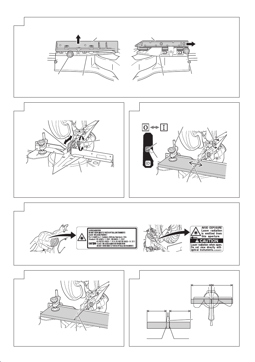
4. Positioning the table insert (Fig. 14)
Table inserts are installed on the turntable. When
shipping the tool from the factory, the table inserts are
so fi xed that the saw blade does not contact them. The
burr of the bottom surface of the workpiece is remarkably
reduced, if the table insert is fi xed so that the gap
between the side surface of the table insert and the saw
blade will be minimum. Before using the tool, eliminate
this gap in accordance with the following procedure.
(1) Loosen the four 5 mm pan head screws securing the
cutting edge plate and with the gap between the left and
right cutting edge plates widened, temporarily tighten all
the 5mm pan head screws.
(2) Then fi x a workpiece (about 200 mm wide) with the vise
assembly and cut it off . Align the cutting face with the
edge of the cutting edge plate, and tighten all the 5 mm
pan head screws.
CAUTION
After adjusting the table insert for right angle cutting, the
table insert will be cut to some extent if it is used for bevel
angle cutting.
When bevel cutting operation is required, adjust the
table insert for bevel angle cutting.
5. Confi rmation for use of sub fence (A) (Fig. 15)
WARNING
This power tool is equipped with a sub fence (A).
In the case of direct angle cutting and left bevel angle
cutting, use the sub fence (A). Then, you can realize
stable cutting of the material with a wide back face.
When right angle cutting, loosen the 6 mm knob bolt,
then remove sub fence (A). Failure to do so may result in
the main body or saw blade coming into contact with the
sub fence (A) and causing injury.
6. Confi rmation for use of sub fence (B) (Fig. 15)
WARNING
When left angle cutting, loosen the 6 mm knob bolt, then
slide the sub fence (B) outward. Failure to do so may
result in the main body or saw blade coming into contact
with the sub fence (B) and causing injury.
This power tool is equipped with a sub fence (B). In the
case of direct angle cutting and right bevel angle cutting,
use the sub fence (B). Then, you can realize stable
cutting of the material with a wide back face. When left
angle cutting, loosen the 6 mm knob bolt, then slide the
sub fence (B) outward, as shown in Fig. 15.
7. Using an ink line (Adjusting the guard) (Fig. 16)
(1) Right angle cutting
Loosen the 6 mm knob bolt and contact the tip of the
guard with the workpiece.
Aligning the ink line on the workpiece with the groove of
the guard, the workpiece is cut on the ink line.
(2) Miter cutting and compound cutting (Miter cutting +
bevel cutting)
Upon lowering the motor section, the lower guard is
raised and the saw blade appears.
Align the ink line with the saw blade.
CAUTION
In some arrangements when the turntable is rotated, the
guard projects from the fence surface. Loosen the 6 mm
knob bolt and push the guard to the retracted position.
Never lift the lower guard while the saw blade is rotating.
When cutting at an angle of 45° to the right or more,
please slide the guard to the rear. (Fig. 16)
The guard
only make contact and adversely aff ect cutting accuracy,
this could also result in damage to the guard.
8. Position adjustment of laser line
Ink lining can be easily made on this tool to the laser
marker. A switch lights up the laser marker (Fig. 1).
Depending upon your cutting choice, the laser line can
be aligned with the left side of the cutting width (saw
blade) or the ink line on the right side.
The laser line is adjusted to the width of the saw blade at
the time of factory shipment. Adjust the positions of the
saw blade and the laser line taking the following steps to
suit the use of your choice.
(1) Light up the laser marker and make a groove of about 5
mm deep on the workpiece that is about 20 mm in height
and 150 mm in width. Hold the grooved workpiece by
vise as it is and do not move it. For grooving work, refer
to “19.
(2) Then, turn the adjuster and shift the laser line. (If you turn
the adjuster clockwise, the laser line will shift to the right
and if you turn it counterclockwise, the laser line will shift
to the left.) When you work with the ink line aligned with
the left side of the saw blade, align the laser line with the
left end of the groove (Fig. 17). When you align it with
the right side of the saw blade, align the laser line with
the right side of the groove.
and sub-fence (A) and sub-fence (B) will not
Groove cutting procedures”.
24
Page 25

(3) After adjusting the position of the laser line, draw a right-
angle ink line on the workpiece and align the ink line
with the laser line. When aligning the ink line, slide the
workpiece little by little and secure it by vise at a position
where the laser line overlaps with the ink line. Work on
the grooving again and check the position of the laser
line. If you wish to change the laser line’s position, make
adjustments again following the steps from (1) to (3).
WARNING
○ Exercise utmost caution in handling a switch trigger for
the position adjustment of the laser line, as the battery
is installed during operation.
If the switch trigger is pulled inadvertently, the saw blade
can rotate and result in unexpected accidents.
○ Do not remove the laser marker to be used for other
purposes.
CAUTION (Fig. 18)
○ Laser radiation - Do not stare into beam.
○ Laser radiation on work table. Do not stare into beam. If
your eye is exposed directly to the laser beam, it can be
hurt.
○ Do not dismantle it.
○ Do not give strong impact to the laser marker (main body
of tool); otherwise, the position of a laser line can go out
of order, resulting in the damage of the laser marker as
well as a shortened service life.
○ Keep the laser marker lit only during a cutting operation.
Prolonged lighting of the laser marker can result in a
shortened service life.
○ Use of controls or adjustments or performance of
procedures other than those specifi ed herein may result
in hazardous radiation exposure.
NOTE
○ Perform cutting by overlapping the ink line with the laser
line.
○
When the ink line and the laser line are overlapped, the
strength and weakness of light will change, resulting in a
stable cutting operation because you can easily discern the
conformity of lines. This ensures the minimum cutting errors.
○ In outdoor or near-the-window operations, it may
become diffi cult to observe the laser line due to the
sunlight. Under such circumstances, move to a place
that is not directly under the sunlight and engage in the
operation.
○ Check and make sure on a periodic basis if the position
of the laser line is in order. As regards the checking
method, draw a right-angle ink line on the workpiece with
the height of about 20 mm and the width of 150 mm, and
check that the laser line is in line with the ink line [The
deviation between the ink line and the laser line should
be less than the ink line width (0.5 mm)]. (Fig. 19)
9. Cutting operation
(1) As shown in Fig. 20 the width of the saw blade is the
width of the cut. Therefore, slide the workpiece to the
right (viewed from the operator’s position) when length
is desired, or to the left when length is desired.
If a laser marker is used, align the laser line with the left
side of the saw blade, and then align the ink line with the
laser line.
(2) After turning on the switch and checking that the saw
blade is rotating at maximum speed, slowly push down
the handle while holding down the lever (A) and bring the
saw blade in the vicinity of the material to be cut.
(3) Once the saw blade contacts the workpiece, push the
handle down gradually to cut into the workpiece.
(4) After cutting the workpiece to the desired depth, turn the
power tool OFF and let the saw blade stop completely
before raising the handle from the workpiece to return it
to the full retract position.
CAUTION
○ For maximum dimensions for cutting, refer to
“SPECIFICATIONS” table.
○
Increased pressure on the handle will not increase the cutting
speed. On the contrary, too much pressure may result in
overload of the motor and/or decreased cutting effi ciency.
○ Confi rm that the trigger switch is turned OFF and the
battery has been removed whenever the tool is not in
use.
○ Always turn the power off and let the saw blade stop
completely before raising the handle from the workpiece.
If the handle is raised while the saw blade is still rotating,
the cut-off piece may become jammed against the saw
blade causing fragments to scatter about dangerously.
○ Every time one cutting of deep-cutting operation is
fi nished, turn the switch off , and check that the saw
blade has stopped. Then raise the handle, and return it
to the full retract position.
○ Be absolutely sure to remove the cut material from the
top of the turntable, and then proceed to the next step.
○ Continued cutting operation can result in overload of the
motor. Touch the motor and if it's hot, stop your cutting
operation once and rest for 10 minutes or so, and then
restart your cutting operation.
10. Cutting narrow workpieces (Press cutting) (Fig. 21)
Slide the hinge down to holder (A), then tighten the slide
securing wing bolt (Fig. 1). Lower the handle to cut the
workpiece. Using the power tool this way will permit
cutting of workpieces of up to 58 mm height × 75 mm
width.
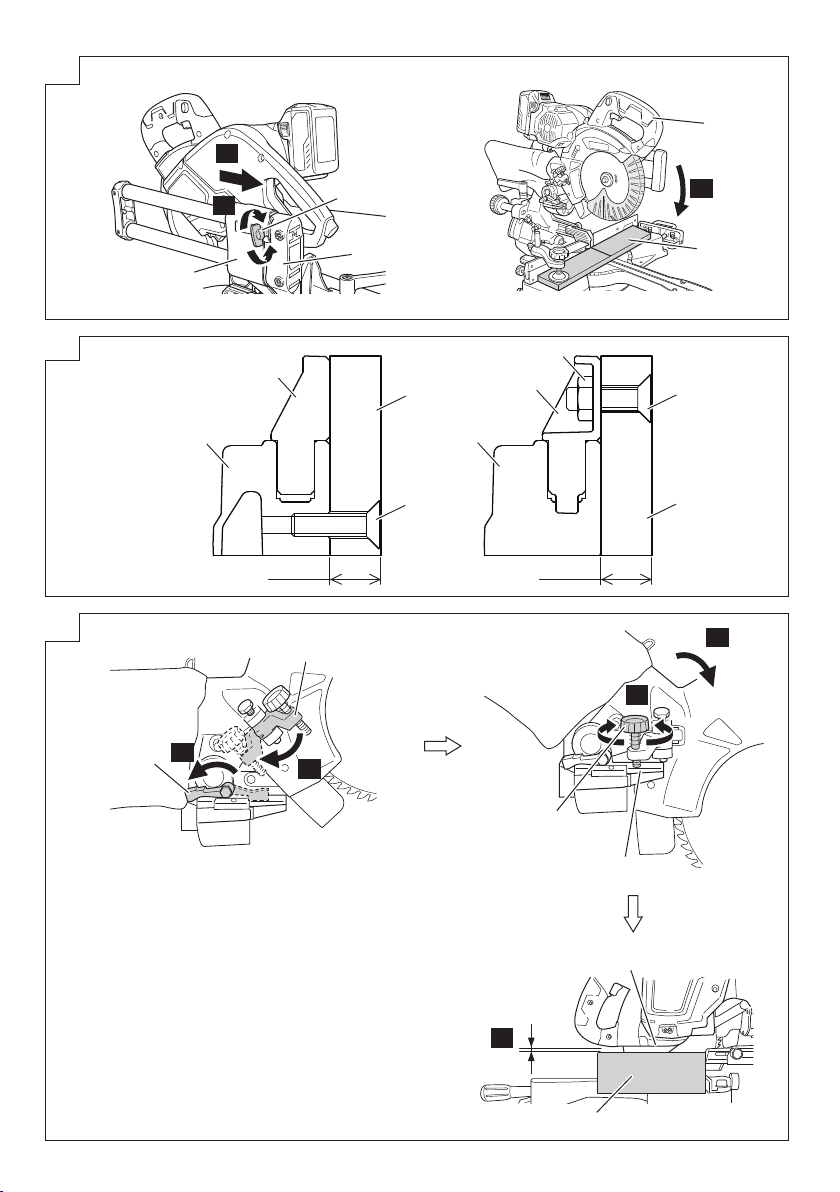
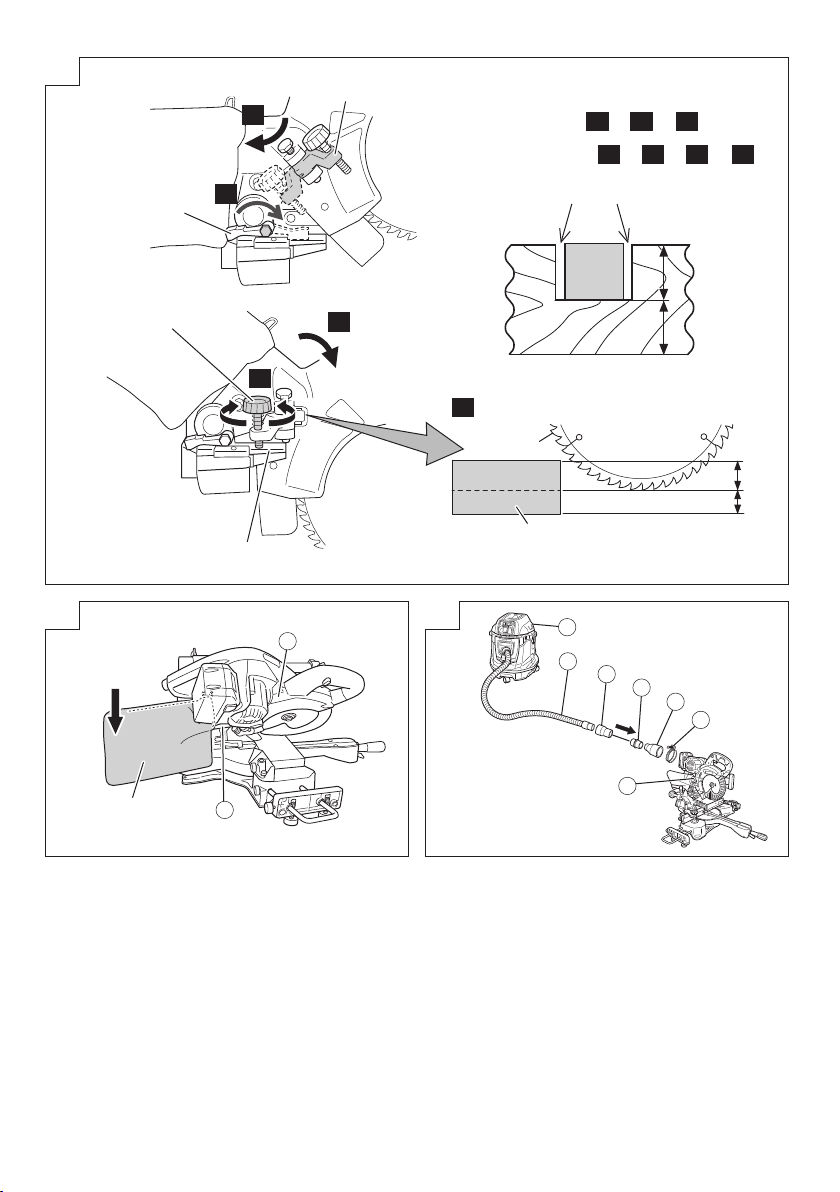
11. Cutting large workpieces (Fig. 22, 23)
There may be case when a complete cutting cannot be
done depending on the height of workpiece. In this case,
mount an auxiliary board with the 6 mm fl at head screws
and the 6 mm nuts using the 6.5 mm holes on the fence
surface (two holes on each side). (Fig. 22)
Refer to “SPECIFICATIONS” for the thickness of the
auxiliary board.
NOTE
When cutting a workpiece exceeding 67 mm in height in
right-angle cutting or 45 mm in left bevel angle cutting or
22 mm in right bevel angle cutting, adjust the lower limit
position so that the base of the motor head will not come
in contact with the workpiece.
To adjust the lower limit position of the saw blade, follow the
procedure (1) and (2) shown in Fig. 23.
(1) Tilt the stopper (B) and turn the stopper holder on the
side of the head towards the rear.
(2) Lower the motor head, and turn the 8 mm depth
adjustment bolt and make adjustments so that there can
be a clearance of 2 mm to 3 mm between the lower limit
position of the motor head and the top of the workpiece
at the saw blade's lower limit position where the head of
the 8 mm depth adjustment bolt contacts the hinge.
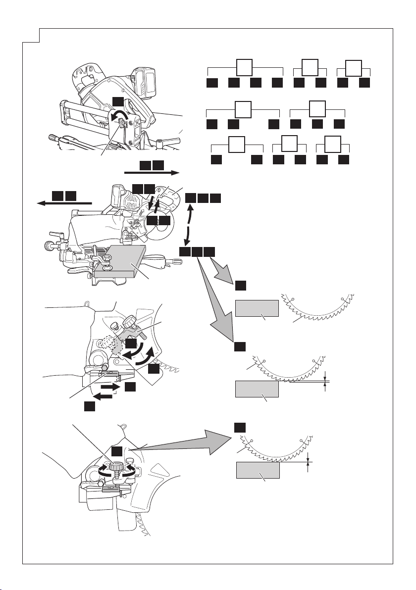
12. Cutting wide workpieces (Slide cutting) (Fig. 24)
(1) Workpieces up to 58 mm high and 310 mm wide:
Loosen the slide securing wing bolt (Fig. 1), grip the
handle and slide the saw blade forward.
Then press down on the handle and slide the saw
blade back to cut the workpiece. This facilitates cutting
of workpieces of up to 58 mm in height and 310 mm in
width.
(2) Workpieces up to 67 mm high and 263 mm wide:
Workpieces of up to 67 mm in height and up to 263 mm
in width can be cut in the same manner as described in
paragraph 11 above.
(3) Spacers (D) can be used to minimize burrs on the
surface of materials when making slide cuts. (Fig. 24-b)
25
Page 26

CAUTION
○ When cutting a workpiece of 67 mm height, adjust the
lower limit position of the motor head so that the gap
between the lower edge of the motor head and the
workpiece will be 2 to 3 mm at the lower limit position.
Refer to "11. Cutting large workpieces".
○ If the handle is pressed down with excessive or lateral
force, the saw blade may vibrate during the cutting
operation and cause unwanted cutting marks on the
workpiece, thus reducing the quality of the cut.
Accordingly, press the handle down gently and carefully.
○ In slide cutting, gently push the handle back (rearwards)
in a single, smooth operation. Stopping the handle
movement during the cut will cause unwanted cutting
marks on the workpiece.
WARNING
○ For slide cutting, follow the procedures.
Forward slide cutting (toward the operator) is very
dangerous because the saw blade could kick upward
from the workpiece. Therefore, always slide the handle
away from the operator.
○ Always return the carriage to the full rear position after
each crosscut operation in order to reduce the risk of
injury.
○ Never put your hand on the side handle during the
cutting operation because the saw blade comes close to
the side handle when the motor head is lowered.
13. Miter cutting procedures
(1) Loosen the side handle and pull up the lever for angle
stoppers. Then, adjust the turntable until the indicator
aligns with desired setting on the miter scale (Fig. 25).
(2) Re-tighten the side handle to secure the turntable in the
desired position.
(3) The miter scale indicates both the cutting angle on the
angle scale and the gradient on the grade scale.
(4) The gradient, which is the ratio of the height to the base
of the triangular section to be removed, may be used
for setting the miter scale instead of the cutting angle, if
desired.
Therefore, to cut a workpiece at a grade of 2/10, set the
indicator to position.
NOTE
○ Positive stops are provided at the right and left of the 0°
center setting, at 15°, 22.5°, 30° and 45° settings.
Check that the miter scale and the tip of the indicator are
properly aligned.
○ Operation of the saw with the miter scale and indicator
out of alignment, or with the side handle not properly
tightened, will result in poor cutting precision.
14. Bevel cutting procedures (Fig. 26)
(1) Loosen the clamp lever and bevel the saw blade to the
left or to the right. When tilting the motor head to the right
pull the set pin (A) towards the rear.
The clamp lever adopts a latchet system. When
contacting the work bench and the main body, pull
the clamp lever in the direction of the arrow mark as
illustrated in Fig. 26, and change the direction of the
clamp lever.
(2) Adjust the bevel angle to the desired setting while
watching the bevel angle scale and indicator, then
secure the clamp lever.
WARNING
When the workpiece is secured on the left or right side
of the blade, the short cut-off portion will come to rest
on the right or left side of the saw blade. Always turn the
power off and let the saw blade stop completely before
raising the handle from the workpiece.
If the handle is raised while the saw blade is still rotating,
the cut-off piece may become jammed against the saw
blade causing fragments to scatter about dangerously.
When stopping the bevel cutting operation halfway, start
cutting after pulling back the motor head to the initial
position.
Starting from halfway, without pulling back, causes the
lower guard to be caught in the cutting groove of the
workpiece and to contact the saw blade.
CAUTION
When cutting a workpiece of 45 mm height in the left 45°
bevel cutting position or a workpiece of 22 mm height in
the right 45° bevel cutting position, adjust the lower limit
position of the motor head so that the gap between the
lower edge of the motor head and the workpiece will be
2 to 3 mm at the lower limit position (refer to “11.
large workpieces” on
15. Compound cutting procedures
Compound cutting can be performed by following the
instructions in 12 and 13 above. For maximum dimensions
for compound cutting, refer to “SPECIFICATIONS” table.
CAUTION
Always secure the workpiece with the right or left
hand and cut it by sliding the round portion of the saw
backwards with the left hand.
It is very dangerous to rotate the turntable to the left
during compound cutting because the saw blade may
come into contact with the hand that is securing the
workpiece.
In case of compound cutting (angle + bevel) by left
bevel, slide the sub-fence (B) outward, and engage in
the cutting operation.
In case of compound cutting (angle + bevel) by right
bevel, remove the sub-fence (A), and engage in the
cutting operation.
16. Cutting long materials
When cutting long materials, use an auxiliary platform
which is the same height as the holder and base of the
special auxiliary equipment.
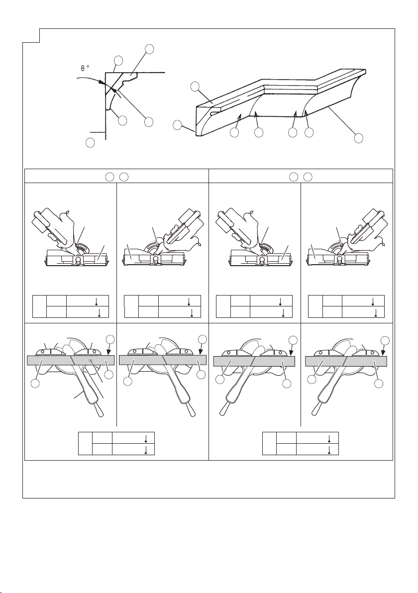
17. Crown molding cutting procedures
Fig. 28-a shows two common crown molding types
having angles of (θ) 38° and 45°.
For the typical crown molding fi ttings, see Fig. 28-b.
Fig. 28 shows the miter angle and the bevel angle
settings that are ideal for the two crown molding types.
NOTE
For convenience, positive stops are provided for the
miter setting (left and right 31.6°) positions.
For miter cut setting
If the turntable has been set to either of the angles
described, move the turntable adjusting side handle a
little to the right and left to stabilize the position and to
properly align the miter angle scale and the tip of the
indicator before the operation starts.
For bevel cut setting
Turn the clamp lever on bevel section to the left and
check that the position is stable and that the bevel angle
scale and the tip of the indicator are properly aligned.
Then tighten the clamp lever.
18. Groove cutting procedures
Grooves in the workpiece can be cut by adjusting the 6
mm depth adjustment bolt (Fig. 29).
(1) Turn the stopper holder on the direction shown in
Fig. 29.
Lower the motor head, and turn the 6 mm depth
adjustment bolt by hand. (Where the head of the 6 mm
depth adjustment bolt contacts the hinge.)
(2) Adjust to the desired cutting depth by setting the
distance between the saw blade and the surface of the
base (Fig. 29).
NOTE
When cutting a single groove at either end of the
workpiece, remove the unneeded portion with a chisel.
page 25).
Cutting
26
Page 27

19. Using the dust bag (Standard accessory) (Fig. 30)
(1) Connect the dust bag with the duct of power tool.
(2) When the dust bag has become full of sawdust, dust will
be blown out of the dust bag when the saw blade rotates.
Check the dust bag periodically and empty it before it
becomes full.
(3) During bevel and compound cutting, attach the dust bag
at the right angle to the base surface.
20. Connecting the dust extractor (Sold separately)
(Fig. 31)
Do not inhale the harmful dusts generated in cutting
operation.
The dust can endanger the health of yourself and
bystanders.
Use of dust extractor can reduce dust related hazards.
By connecting with dust extractor through adapter,
joint and dust collection adapter, most of dust can be
collected.
Connect the dust extractor with adapter.
Safeguard Function LED Light Display Corrective Action
Overburden Protection
Temperature Protection
On 0.1 second/off 0.1 second
On 0.5 second/off 0.5 second
(1) Connect in order of hose (id 38 mm × 3 m long) and
adapter (Dust extractor’s Standard accessory) joint
(Optional accessory) and dust collection adapter
(Optional accessory) with the duct of power tool.
Connection is done by pressing in the direction of the
arrow. (Fig. 31)
The dust collection adapter (Optional accessory) is fi xed
to the duct by a hose band. (Optional accessory)
21. Using the LED light (Fig. 32)
LED LIGHT WARNING SIGNALS
This product features functions that are designed to protect
the tool itself as well as the battery. While the switch is
pulled, if any of the safeguard functions are triggered during
operation, the LED light will blink as described in Table 3.
When any of the safeguard functions are triggered,
immediately remove your fi nger from the switch and follow
the instructions described under corrective action.
Table 3
Remove the cause of the overburdening.
Allow the tool and battery to thoroughly cool.
MOUNTING AND DISMOUNTING SAW
BLADE
WARNING
To prevent an accident or personal injury, always turn
off the trigger switch and disconnect the battery from the
power tool before removing or installing a saw blade.
1. Mounting the saw blade (Fig. 33)
(1) Press in spindle lock and loosen left hex. 7 mm socket
bolt with 5 mm hex. bar wrench (standard accessory).
Since the left hex. 7 mm socket bolt is left-hand threaded,
loosen by turning it to the right.
NOTE
If the spindle lock cannot be easily pressed in to lock the
spindle, turn the left hex. 7 mm socket bolt with 5 mm
hex. bar wrench (standard accessory) while applying
pressure on the spindle lock.
The saw blade spindle is locked when the spindle lock is
pressed inward.
(2) Remove the bolt and washer (B)
(3) Lift the lower guard and mount the saw blade.
WARNING
When mounting the saw blade, confi rm that the rotation
indicator mark on the saw blade and the rotation direction
of the gear case are properly matched.
(4) Thoroughly clean washer (A) and the left hex. 7 mm
socket bolt, and install them onto the saw blade spindle.
(5) Press in the spindle lock and tighten the left hex.
7 mm socket bolt by turning it to the left by standard
accessories (5 mm hex. bar wrench).
CAUTION
○ A dust guide is installed inside behind the hinge. When
removing or installing the saw blade, do not make
contact with the dust guide. Contact may break or chip
saw blade tips.
○ Tighten the left hex. 7 mm socket bolt so it does not
come loose during operation.
○ Confi rm the left hex. 7 mm socket bolt has been properly
tightened before the power tool is started.
○ Confi rm that the lower guard has closed position.
2. Dismounting the saw blade
Dismount the saw blade by reversing the mounting
procedures described in paragraph 1 above.
The saw blade can easily be removed after lifting the
lower guard.
CAUTION
Never attempt to install saw blades except
180 mm in diameter.
HOW TO RECHARGE USB DEVICE
(UC18YSL3)
(1) Select a charging method
○ Charging a USB device from a electrical outlet (Fig.
34-a)
○ Charging a USB device and battery from a electrical
outlet (Fig. 34-b)
(2) How to recharge USB device (Fig. 35)
(3) When charging of USB device is completed (Fig. 36)
TRANSPORTATION OF THE MAIN
BODY
The vice assembly could be dropped during transportation.
Either remove the assembly or slip a piece of wood between
the vice to fi rmly secure it. (Fig. 37)
Drop the head and insert the locking pin (see page 23
"Releasing the locking pin").
Turn and loosen the side handle, turn the turntable as far
right as it will go, and secure the turntable by turning the
handle to the fi xed position.This will make the main body
even more compact.
When transporting the main body, carry it in your arms,
holding the grip located on the base with both hands or carry
handle.
27
Page 28

MAINTENANCE AND INSPECTION
WARNING
To avoid an accident or personal injury, always confi rm
the trigger switch is turned OFF and that the battery
has been disconnected from the power tool before
performing any maintenance or inspection of this tool.
Report to qualifi ed person as soon as possible, if you
discover the fault of machine including guards or blade
saw.
1. Inspecting the saw blade
Always replace the saw blade immediately upon the fi rst
sign of deterioration or damage.
A damaged saw blade can cause personal injury and
a worn saw blade can cause ineff ective operation and
possible overload to the motor.
CAUTION
Never use a dull saw blade. When a saw blade is dull,
its resistance to the hand pressure applied by the tool
handle tends to increase, making it unsafe to operate the
power tool.
2. Inspecting the mounting screws
Regularly inspect all mounting screws and ensure that
they are properly tightened. Should any of the screws
be loose, re-tighten them immediately. Failure to do so
could result in serious hazard.
3. Inspection of terminals (tool and battery)
Check to make sure that swarf and dust have not
collected on the terminals.
On occasion check prior, during and after operation.
CAUTION
Remove any swarf or dust which may have collected on
the terminals.
Failure to do so may result in malfunction.
4. Maintenance of the motor
The motor unit winding is the very “heart” of the power
tool. Exercise due care to ensure the winding does not
become damaged and/or wet with oil or water.
5. Inspecting the lower guard for proper operation
Before each use of the tool, test the lower guard (Fig. 5)
to assure that it is in good condition and that it moves
smoothly.
Never use the tool unless the lower guard operates
properly and it is in good mechanical condition.
6. Storage
After operation of the tool has been completed, check
that the following has been performed:
(1) Trigger switch is in OFF position,
(2) Battery has been removed from the power tool,
When the tool is not in use, keep it stored in a dry place
below 40°C and out of the reach of children.
NOTE
Storing lithium-ion batteries.
Make sure the lithium-ion batteries have been fully
charged before storing them.
Prolonged storage (3 months or more) of batteries with
a low charge may result in performance deterioration,
signifi cantly reducing battery usage time or rendering
the batteries incapable of holding a charge.
However, signifi cantly reduced battery usage time may
be recovered by repeatedly charging and using the
batteries two to fi ve times.
If the battery usage time is extremely short despite
repeated charging and use, consider the batteries dead
and purchase new batteries.
7. Replacement of guard
After long-term use, the blade slot in the guard may
widen and require replacement. If the blade slot should
widen, replace the guard with a new one (Fig. 16). After
replacing, make a groove on it.
8. Lubrication
Lubricate the following sliding surfaces once a month
to keep the power tool in good operating condition for a
long time.
Use of machine oil is recommended.
Oil supply points:
* Rotary portion of hinge
* Rotary portion of holder (A)
* Rotary portion of vise assembly
9. Cleaning
Periodically remove chips and other waste material
from the surface of the power tool with a damp, soapy
cloth. To avoid a malfunction of the motor, protect it from
contact with oil or water.
If the laser line becomes invisible due to chips and the
like adhered onto the window of the laser marker's light-
emitting section, wipe and clean the window with a dry
cloth or a soft cloth moistened with soapy water, etc.
Clean the machine, duct, lower guard, by blowing with
dry air from an air gun or other tool. (Fig. 38)
SELECTING ACCESSORIES
The accessories of this machine are listed on page 32.
CAUTION
Repair, modifi cation and inspection of HiKOKI Power
Tools must be carried out by a HiKOKI Authorized
Service Center.
Especially laser device should be maintained by the
authorized agent by laser manufacturer.
Always assign the repair of laser device to HiKOKI
Authorized Service Center.
In the operation and maintenance of power tools, the
safety regulations and standards prescribed in each
country must be observed.
Important notice on the batteries for the HiKOKI
cordless power tools
Please always use one of our designated genuine
batteries. We cannot guarantee the safety and
performance of our cordless power tool when used with
batteries other than these designated by us, or when
the battery is disassembled and modifi ed (such as
disassembly and replacement of cells or other internal
parts).
NOTE
Due to HiKOKI’s continuing program of research and
development the specifi cations herein are subject to change
without prior notice.
28
Page 29

TROUBLESHOOTING
Use the inspections in the table below if the tool does not operate normally. If this does not remedy the problem, consult
your dealer or the HiKOKI Authorized Service Center.
1. Power tool
Symptom Possible cause Remedy
Tool doesn’t run No remaining battery power. Charge the battery.
The battery is not fully installed. Insert the battery into the tool until you hear
Tool suddenly stopped Tool was overburdened. Get rid of the problem causing the
The battery is overheated. Let the battery cool down.
Cannot be tilted The clamp lever has not been loosened. Loosen the clamp lever and then tilt the tool.
Cannot be tilted to the right Set pin (A) has not been pulled out. Tilt to the right after pulling out set pin (A).
The clamp lever has not been loosened. Loosen the clamp lever and then tilt.
Sawblade is dull The sawblade is worn down or missing
Cannot cut with precision The operation parts of the tool are not fully
Switch cannot be pulled Switch lock is not pressed in enough. Press in the switch lock all the way until it
Battery cannot be installed Attempting to install a battery other than that
teeth.
Bolt is loose. Tighten the bolt.
The sawblade has been installed in reverse. Install the sawblade in the correct direction.
fi xed.
Material cannot be fi xed in the correct
position.
specifi ed for the tool.
a click.
overburden.
After adjusting the loosened component,
make sure to tighten it once again.
Exchange with a new product.
Fully install the clamp lever and side handle.
Remove any foreign material from the fence
or turntable.
In some cases, proper position cannot be
fi xed due to a curve in the material.
Try to fi x a fl at surface with the fence or
turntable.
strikes the back
Please install a multi volt type battery.
29
Page 30

2. Charger
Symptom Possible cause Remedy
The charge indicator lamp
is rapidly fl ickers purple,
and battery charging
doesn’t begin.
The charge indicator lamp
blinks red, and battery
charging doesn’t begin.
Battery usage time is short
even though the battery is
fully charged.
The battery takes a long
time to charge.
The USB power lamp
has switched off and the
USB device has stopped
charging.
USB power lamp does not
switch off even though the
USB device has fi nished
charging.
It is unclear what the
charging status of a USB
device is, or whether its
charging is complete.
Charging of a USB device
pauses midway.
Charging of the USB device
pauses midway when the
battery and the USB device
are being charged at the
same time.
Charging of the USB
device doesn’t start when
the battery and the USB
device are being charged
at the same time.
The battery is not inserted all the way. Insert the battery fi rmly.
There is foreign matter in the battery
terminal or where the battery is attached.
The battery is not inserted all the way. Insert the battery fi rmly.
The battery is overheated. If left alone, the battery will automatically
The battery’s life is depleted. Replace the battery with a new one.
The temperature of the battery, the charger,
or the surrounding environment is extremely
low.
The charger’s vents are blocked, causing its
internal components to overheat.
The cooling fan is not running. Contact a HiKOKI Authorized Service
The battery’s capacity has become low. Replace the battery with one that has
The USB power lamp lights up green to
indicate that USB charging is possible.
The USB power lamp does not switch off
even when charging is complete.
The charger was plugged into an electrical
socket while the USB device was being
charged using the battery as the power
source.
A battery was inserted into the charger while
the USB device was being charged using a
power socket as the power source.
The battery has become fully charged. This is not a malfunction.
The remaining battery capacity is extremely
low.
Remove the foreign matter.
begin charging if its temperature decreases,
but this may reduce battery life. It is
recommended that the battery be cooled in
a well-ventilated location away from direct
sunlight before charging it.
Charge the battery indoors or in another
warmer environment.
Avoid blocking the vents.
Center for repairs.
capacity remaining.
Plug the charger’s power plug into an
electric socket.
This is not a malfunction.
Examine the USB device that is charging to
confi rm its charging status.
This is not a malfunction.
The charger pauses USB charging for about
5 seconds when it is diff erentiating between
power sources.
The charger pauses USB charging for
about 5 seconds while it checks whether
the battery has successfully completed
charging.
This is not a malfunction.
When the battery capacity reaches a certain
level, USB charging automatically begins.
30
Page 31

C3607DRA
(2XC)
C3607DRA
(NN)
111221212
111221–– –
31
Page 32

UC18YSL3 (14.4V – 18V) 329897 Multi Volt (Li-ion)
329818 329819
374928
307947
322321
374637
996722
322047
996722
996247
371730
322283
374638 998844
944459
322955
374636
323334
Page 33

Page 34

Page 35

35
Page 36

Shinagawa Intercity Tower A, 15-1, Konan 2-chome,
Minato-ku, Tokyo, Japan
Code No. C99731612 N
Printed in Japan
901
 Loading...